WO2018100803A1 - 蛍光タンパク質複合体、および蛍光タンパク質の発光方法 - Google Patents
蛍光タンパク質複合体、および蛍光タンパク質の発光方法 Download PDFInfo
- Publication number
- WO2018100803A1 WO2018100803A1 PCT/JP2017/028174 JP2017028174W WO2018100803A1 WO 2018100803 A1 WO2018100803 A1 WO 2018100803A1 JP 2017028174 W JP2017028174 W JP 2017028174W WO 2018100803 A1 WO2018100803 A1 WO 2018100803A1
- Authority
- WO
- WIPO (PCT)
- Prior art keywords
- fluorescent protein
- wavelength
- fluorescence
- excitation
- xaa
- Prior art date
- Legal status (The legal status is an assumption and is not a legal conclusion. Google has not performed a legal analysis and makes no representation as to the accuracy of the status listed.)
- Ceased
Links
Images


Classifications
-
- C—CHEMISTRY; METALLURGY
- C07—ORGANIC CHEMISTRY
- C07K—PEPTIDES
- C07K19/00—Hybrid peptides, i.e. peptides covalently bound to nucleic acids, or non-covalently bound protein-protein complexes
-
- C—CHEMISTRY; METALLURGY
- C12—BIOCHEMISTRY; BEER; SPIRITS; WINE; VINEGAR; MICROBIOLOGY; ENZYMOLOGY; MUTATION OR GENETIC ENGINEERING
- C12N—MICROORGANISMS OR ENZYMES; COMPOSITIONS THEREOF; PROPAGATING, PRESERVING, OR MAINTAINING MICROORGANISMS; MUTATION OR GENETIC ENGINEERING; CULTURE MEDIA
- C12N15/00—Mutation or genetic engineering; DNA or RNA concerning genetic engineering, vectors, e.g. plasmids, or their isolation, preparation or purification; Use of hosts therefor
- C12N15/09—Recombinant DNA-technology
-
- C—CHEMISTRY; METALLURGY
- C12—BIOCHEMISTRY; BEER; SPIRITS; WINE; VINEGAR; MICROBIOLOGY; ENZYMOLOGY; MUTATION OR GENETIC ENGINEERING
- C12N—MICROORGANISMS OR ENZYMES; COMPOSITIONS THEREOF; PROPAGATING, PRESERVING, OR MAINTAINING MICROORGANISMS; MUTATION OR GENETIC ENGINEERING; CULTURE MEDIA
- C12N5/00—Undifferentiated human, animal or plant cells, e.g. cell lines; Tissues; Cultivation or maintenance thereof; Culture media therefor
- C12N5/10—Cells modified by introduction of foreign genetic material
Definitions
- the present invention relates to a fluorescent protein complex and a fluorescent protein luminescence method.
- Fluorescent proteins such as GFP (Green Fluorescent Protein) and YFP (Yellow Fluorescent Protein) are generally used (Non-patent Document 1).
- the fluorescent protein is used for various purposes such as research.
- each of the fluorescent proteins has a specific excitation wavelength and a maximum excitation wavelength, and a fluorescence wavelength and an emission maximum wavelength, each of the fluorescent proteins emits light by excitation and detects its emission. Use may be optically limited depending on excitation conditions and luminescence detection conditions.
- an object of the present invention is to provide a new fluorescent protein that can expand optical conditions depending on the fluorescent protein, for example.
- the fluorescent protein complex of the present invention comprises: Including a first fluorescent protein and a second fluorescent protein, The first fluorescent protein and the second fluorescent protein are linked;
- the combination of the first fluorescent protein and the second fluorescent protein is a combination in which the fluorescence wavelength (L1) of the first fluorescent protein and the excitation wavelength (E2) of the second fluorescent protein overlap. It is characterized by that.
- the fluorescent protein luminescence method of the present invention comprises: Irradiating the fluorescent protein complex of the present invention with light having an excitation wavelength of the first fluorescent protein in the fluorescent protein complex, By irradiating the first fluorescent protein with light having an excitation wavelength of the first fluorescent protein, the first fluorescent protein is caused to emit light, The second fluorescent protein in the fluorescent protein complex is excited by the light emission of the first fluorescent protein to cause the second fluorescent protein to emit light.
- the gene encoding the fluorescent protein complex of the present invention is: A first nucleic acid sequence encoding a first fluorescent protein and a second nucleic acid sequence encoding a second fluorescent protein; The first nucleic acid sequence and the second nucleic acid sequence are linked so as to be expressed as a complex in which the first fluorescent protein and the second fluorescent protein are linked; The combination of the first fluorescent protein and the second fluorescent protein is a combination in which the fluorescence wavelength (L1) of the first fluorescent protein and the excitation wavelength (E2) of the second fluorescent protein overlap. It is characterized by.
- the expression vector of the present invention is characterized by including a gene encoding the fluorescent protein complex of the present invention.
- the transformant of the present invention is characterized by including the gene encoding the fluorescent protein complex of the present invention or the expression vector.
- the present invention by combining the first fluorescent protein and the fluorescent protein under the above-described conditions, for example, when the excitation light from the outside is different from the excitation conditions of the second fluorescent protein or maximum excitation Even when the wavelength deviates from the wavelength, the second fluorescent protein can emit light by excitation due to light emission of the first fluorescent protein. For this reason, according to this invention, compared with the case where a fluorescent protein is used independently, the setting of a wider optical condition is attained, for example.
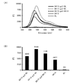
- FIG. 1 is a graph showing fluorescence intensity at an excitation wavelength of 400 nm and a fluorescence detection wavelength of 516 nm in Example 2.
- 2A is a graph showing the fluorescence intensity in the excitation wavelength of 400 nm and a predetermined fluorescence wavelength region in Example 3
- FIG. 2B is a graph showing the maximum fluorescence intensity in the predetermined fluorescence wavelength region. is there.
- FIG. 3 is a graph showing the fluorescence intensity at the excitation wavelength and the fluorescence wavelength in Example 3.
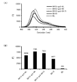
- 4A is a graph showing the fluorescence intensity in the excitation wavelength of 400 nm and a predetermined fluorescence wavelength range in Example 4
- FIG. 4B is a graph showing the maximum fluorescence intensity in the predetermined fluorescence wavelength range. is there.
- FIG. 5 is a graph showing the fluorescence intensity at the excitation wavelength and the fluorescence wavelength in Example 4.
- the fluorescent protein complex of the present invention includes, for example, the emission intensity (I2 E1 ) when the second fluorescent protein excites the second fluorescent protein with the excitation wavelength (E1) of the first fluorescent protein,
- the fluorescence intensity (I2 L1 ) when the second fluorescent protein is excited at the fluorescence wavelength (L1) of one fluorescent protein is a protein that satisfies the relationship of I2 E1 ⁇ I2 L1 .
- the first fluorescent protein and the second fluorescent protein are different proteins.
- the maximum excitation wavelength of the first fluorescent protein is different from the maximum excitation wavelength of the second fluorescent protein.
- the fluorescence wavelength (L1) of the first fluorescent protein and the excitation wavelength (E2) of the second fluorescent protein include wavelengths of 350 to 650 nm.
- the fluorescence wavelength (L1) of the first fluorescent protein includes the maximum excitation wavelength (E2 max ) of the second fluorescent protein.
- the fluorescence wavelength (L2) of the second fluorescent protein includes a range of 490 to 650 nm.
- the first fluorescent protein and the second fluorescent protein are linked via a linker.
- the linker is a peptide linker.
- the peptide linker includes a glycine serine linker region.
- the glycine serine linker region has a peptide unit consisting of the amino acid sequence of SEQ ID NO: 48 (GGGGS).
- the fluorescent protein complex of the present invention is, for example, a linker in which 1 to 3 peptide units are linked to the glycine serine linker region.
- the luminescent protein luminescence method of the present invention further includes, for example, a step of detecting luminescence of the second fluorescent protein.
- the first nucleic acid sequence and the second nucleic acid sequence are linked via a nucleic acid sequence encoding a linker.
- the fluorescent protein complex of the present invention as described above, Including a first fluorescent protein and a second fluorescent protein, The first fluorescent protein and the second fluorescent protein are linked;
- the combination of the first fluorescent protein and the second fluorescent protein is a combination in which the fluorescence wavelength (L1) of the first fluorescent protein and the excitation wavelength (E2) of the second fluorescent protein overlap. It is characterized by that.
- the fluorescent protein complex of the present invention excites the second fluorescent protein by the light emission of the first fluorescent protein. Therefore, it can also be referred to as, for example, a FRET type fluorescent protein complex.
- the present invention is not limited by the function of so-called “FRET (fluorescence energy transfer)”.
- the fluorescence wavelength (L1) of the first fluorescent protein and the excitation wavelength (E2) of the second fluorescent protein overlap.
- the other conditions are not particularly limited.
- the “excitation wavelength of a fluorescent protein” refers to the wavelength of excitation light capable of emitting the fluorescent protein
- the “fluorescence wavelength of the fluorescent protein” refers to the wavelength of the fluorescence emitted from the fluorescent protein by excitation. That's it.
- the fluorescent protein of interest is the second fluorescent protein
- the fluorescent protein that emits light having a fluorescent wavelength that overlaps the excitation wavelength of the second fluorescent protein is The first fluorescent protein.
- the FRET type fluorescent protein complex of the present invention for example, it is possible to obtain luminescence with stronger fluorescence intensity than when the first fluorescent protein or the second fluorescent protein is used alone.
- the second fluorescent protein is excited by light emission of the first fluorescent protein.
- the second fluorescent protein is, for example, a protein that is excited at the fluorescence wavelength of the first fluorescent protein.
- the second fluorescent protein may be a protein that can be excited by the light emission of the first fluorescent protein and can emit light.
- the second fluorescent protein may emit light or emit light by excitation light irradiated on the first fluorescent protein. It does not have to be.
- the FRET fluorescent protein complex of the present invention for example, light emission with a stronger light emission intensity can be obtained as compared with the case where the first fluorescent protein and the second fluorescent protein are excited individually to emit light. You can also.
- the second fluorescent protein includes, for example, the emission intensity (I2 E1 ) when the second fluorescent protein is excited with the excitation wavelength (E1) of the first fluorescent protein, and the fluorescence of the first fluorescent protein.
- Examples include proteins satisfying the relationship of I2 E1 ⁇ I2 L1 with the emission intensity (I2 L1 ) when the second fluorescent protein is excited at the wavelength (L1). If it is such a second fluorescent protein, the FRET fluorescent protein complex of the present invention has, for example, the first fluorescent protein more than the case where the second fluorescent protein is excited with the excitation wavelength (E1) of the first protein.
- the second fluorescent protein is indirectly excited by the fluorescence wavelength (L1) emitted from the fluorescent protein, and can emit more intense light.
- the fluorescence wavelength (L1) of the first fluorescent protein and the excitation wavelength (E2) of the second fluorescent protein only need to include overlapping wavelengths as described above.
- the overlapping wavelengths are not particularly limited, and can be appropriately set according to the types of the first fluorescent protein and the second fluorescent protein.
- the fluorescence wavelength (L1) of the first fluorescent protein may include, for example, the maximum excitation wavelength (E2 max ) of the second fluorescent protein.
- E2 max the maximum excitation wavelength of the second fluorescent protein.
- the second fluorescent protein is caused to emit light more efficiently and with high intensity by excitation of the second fluorescent protein by light emission of the first fluorescent protein. be able to.
- the fluorescence maximum wavelength (L1 max ) of the first fluorescent protein is, for example, 511 to 519 nm.
- the maximum excitation wavelength (E2 max ) of the second fluorescent protein is, for example, 501 to 509 nm and 506 to 514 nm.
- the fluorescence maximum wavelength (L2 max ) of the second fluorescent protein is, for example, 511 to 519 nm or 516 to 524 nm.
- the first fluorescent protein and the second fluorescent protein may be, for example, the same protein or different proteins.
- the first fluorescent protein and the second fluorescent protein are in the same excitation wavelength range, for example, the first fluorescent protein is excited with a predetermined excitation wavelength (E1) included in the excitation wavelength range, and the first fluorescent protein The fluorescent protein is allowed to emit light, and the second fluorescent protein (same as the first fluorescent protein) is excited at the fluorescent wavelength (L1) included in the excitation wavelength range, and can be caused to emit light.
- the difference between the maximum excitation wavelength (E1 max ) of the first fluorescent protein and the maximum excitation wavelength (E2 max ) of the second fluorescent protein is not particularly limited.
- the maximum excitation wavelength (E1 max ) of the first fluorescent protein is not particularly limited and is, for example, in the range of 396 to 404 nm, 401 to 409 nm.
- the excitation wavelength (E1) of the first fluorescent protein is not particularly limited, and includes, for example, a range of 350 to 650 nm.
- the maximum excitation wavelength (E2 max ) of the second fluorescent protein is not particularly limited, and is as described above, for example.
- the excitation wavelength (E2) of the second fluorescent protein is not particularly limited.
- the first fluorescent protein and the second fluorescent protein may each have one fluorescent peak or two or more fluorescent peaks obtained by changing the excitation wavelength, for example.
- the excitation wavelength can be set in a range in which emission of a fluorescence wavelength including a desired peak is generated.
- the first fluorescent protein and the second fluorescent protein may be directly connected or indirectly connected.
- the first fluorescent protein and the second fluorescent protein are linked via, for example, a linker.
- the linker is not particularly limited as long as the first fluorescent protein and the second fluorescent protein can independently maintain their properties, for example.
- the linker is, for example, a peptide linker.
- the peptide linker is not particularly limited, and examples thereof include a peptide linker including a glycine serine linker region.
- a glycine serine linker is a peptide comprising a glycine residue and a serine residue.
- the peptide linker may include only the glycine serine linker region or may include the glycine serine linker region.
- the glycine serine linker is hereinafter also referred to as “GS linker”, and the glycine serine linker region is hereinafter also referred to as “GS linker region”.
- the glycine serine linker region has, for example, a peptide unit consisting of the amino acid sequence of SEQ ID NO: 48 (GGGGS).
- the number (n) of the peptide units is not particularly limited, and n is a positive integer, for example, 1 to 3, and 1 to 2.
- the glycine serine linker region is represented by (GGGGS) n , for example.
- the peptide linker may include the glycine serine linker region, and in this case, the region other than the glycine serine linker region is not particularly limited.
- the FRET fluorescent protein complex of the present invention is prepared, for example, by genetic engineering, it can be synthesized using the expression vector of the present invention described later.
- the expression vector includes, for example, a nucleic acid sequence encoding the first fluorescent protein, a nucleic acid sequence encoding the second fluorescent protein, and optionally a nucleic acid sequence encoding the glycine serine linker region, and a restriction enzyme site. It can be constructed by linking to a vector serving as a backbone.
- the other region in the peptide linker may be, for example, a peptide region derived from a restriction enzyme site for linking the nucleic acid sequences.
- other regions other than the glycine serine linker region are not particularly limited.
- the length (number of amino acid residues) is 1 to 3, 1 to 2.
- the position of the other region is not particularly limited, and may be, for example, the C-terminal side, the N-terminal side, or both the C-terminal side and the N-terminal side of the glycine serine linker. It may be.
- the length (number of amino acid residues) of the peptide linker is not particularly limited, and the lower limit thereof is, for example, 1, 5, 8, 10, 13, and the upper limit thereof, for example, 18, 15, 13, 10 , 8.
- the FRET type fluorescent protein complex of the present invention may further have a peptide addition region, for example, upstream of the first fluorescent protein.
- the FRET fluorescent protein complex of the present invention is prepared, for example, by genetic engineering, it can be synthesized using the expression vector of the present invention described later.
- the expression vector includes, for example, a nucleic acid sequence encoding the first fluorescent protein, a nucleic acid sequence encoding the second fluorescent protein, and optionally a nucleic acid sequence encoding the glycine serine linker region, and a restriction enzyme site. It can be constructed by linking to a vector serving as a backbone.
- a peptide region derived from a restriction enzyme site for linking to the expression vector may be added as the peptide addition region.
- the length (number of amino acid residues) of the peptide addition region is not particularly limited, and is, for example, 1 to 4, 1 to 3, or 1 to 2.
- the FRET type fluorescent protein complex of the present invention can excite the second fluorescent protein by the light emission of the first fluorescent protein and cause the second fluorescent protein to emit light.
- a protein excited by black light is the second fluorescent protein, and is excited by UV light and emits light in the wavelength range of black light.
- the combination which uses protein as said 1st fluorescent protein can be illustrated.
- the first fluorescent protein is a fluorescent protein that is excited by UV light and emits light having a fluorescent wavelength included in the black light wavelength region when excited, the first fluorescent protein is UV-excited.
- the first fluorescent protein can emit light.
- the emitted light is a fluorescence wavelength included in the black light wavelength range, the emitted light can excite the second fluorescent protein without using a black light.
- Examples of such a combination of the first fluorescent protein and the second fluorescent protein include the following combinations.
- the first fluorescent protein and the second fluorescent protein are directly or indirectly linked and exist as a constituent element of the FRET fluorescent protein complex. For this reason, for example, when the FRET fluorescent protein complex is expressed by genetic engineering, the start codon of the complex encodes the first methionine residue of the first fluorescent protein, and thus the second fluorescent protein The first methionine residue of the protein may be deleted.
- examples of the combination of the first fluorescent protein, the glycine serine linker region in the peptide linker, and the second fluorescent protein include the following combinations.
- the number n of GS linker region (GGGGGS) n repeating units in the peptide linker is not particularly limited, and is, for example, 1 to 3, and amino acids in other regions N m in the peptide linker Residue N is not particularly limited and may be any amino acid (Xaa). For example, all may be the same or different, and the number m of repeating units is not particularly limited, and the peptide addition region and It is the same.
- the FRET type fluorescent protein complex in the combination shown in Table 4 can be represented by the following sequence, for example.
- the first fluorescent protein and the second fluorescent protein can be used in combination with, for example, the following fluorescent proteins in addition to those described above.
- (F1) consists of the amino acid sequence of SEQ ID NO: 1, in the amino acid sequence of the SEQ ID NO: 1, is 52 amino acid Xaa 52 is any amino acid, 133 amino acid Xaa 133 is any amino acid, 154 amino acid Xaa 154 is, in 52 th amino acid Xaa 52, 133 amino acid Xaa 133, and 154 amino acid sequences other than the amino acid Xaa 154 protein (F2) wherein any amino acid (F1), 1 or several amino acids are deleted, substituted, inserted and / or added in the amino acid sequences, and proteins (F3) said with fluorescent activity (F1) of 52 amino acid Xaa 52, 133 amino acid Xaa 133, Amino acids other than amino acid Xaa 154 at position 154 A protein having an amino acid sequence having 80% or more identity to the amino acid sequence and having fluorescence activity
- the 52nd, 133rd, and 154th amino acids interact with, for example, the chromophore of the protein.
- the protein can adjust the fluorescent activity of the protein by, for example, making the 52nd, 133rd, and 154th amino acids arbitrary amino acids.
- relatively low wavelength excitation light for example, ultraviolet light ( The same applies to the following)
- a protein that emits stronger fluorescence and a protein that emits stronger fluorescence when excited with excitation light of the same intensity can be obtained.
- amino acids (X) surrounded by three squares correspond to the first amino acid corresponding to Xaa 52 , the second amino acid corresponding to Xaa 133 , and the third amino acid corresponding to Xaa 154 .
- the first amino acid is the amino acid corresponding to Xaa 198
- the second amino acid is the amino acid corresponding to Xaa 205 .
- Xaa 52 is an arbitrary amino acid.
- the arbitrary amino acid is A, C, D, E, F, G, H, I, K, L, M, N, P, Q, R, S, T, V, W, or Y, preferably Is C, F, H, K, M, or T.
- it is more preferably C, M, or T because it emits stronger fluorescence even in excitation light having a relatively low wavelength.
- Xaa 52 emits stronger fluorescence when excited with excitation light having the same intensity, and is more preferably H.
- Xaa 133 is an arbitrary amino acid.
- the arbitrary amino acid is A, C, D, E, F, G, H, I, K, L, M, N, P, Q, R, S, T, V, W, or Y, preferably Is L, Q, S, or T.
- Xaa 133 emits stronger fluorescence when excited with excitation light having the same intensity, and is more preferably T.
- Xaa 154 is an arbitrary amino acid.
- the arbitrary amino acid is A, C, D, E, F, G, H, I, K, L, M, N, P, Q, R, S, T, V, W, or Y, preferably Is A, H, I, K, L, Q, V, or Y.
- A, I, L, V, or Y since it emits stronger fluorescence even in excitation light having a relatively low wavelength, A, I, L, V, or Y.
- Xaa 154 emits stronger fluorescence when excited with excitation light having the same intensity, and is more preferably K.
- the combination of Xaa 52 , Xaa 133 , and Xaa 154 is not particularly limited, and for example, Xaa 52 is, for example, C, F, H, K, M, or T; Xaa 133 is, for example, L, Q, S, or T; Xaa 154 is, for example, A, H, I, K, L, Q, V, or Y.
- Xaa 52 is, for example, C, M, or T
- Xaa 133 is, for example, L, Q, S, or T
- Xaa 154 is, for example, A, I, L, V, or Y.
- (F1) is also referred to as (B1).
- (F1) ) Is (B1), the (F2) and (F3) are also referred to as (B2) and (B3), respectively.
- (B2) and (B3) are, for example, (F1) in (B1), (F2) in (B2) in (F2) and (F3), ( F3) can be read as (B3), and the description can be used.
- the combination of Xaa 52 , Xaa 133 , and Xaa 154 is, for example, any one of the following (aa1) to (aa11) and (aa12). Further, in the protein, a combination of Xaa 52, Xaa 133, and Xaa 154 can, for example, even in the excitation light of the relatively low wavelength, since the emit stronger fluorescence, the following (aa1), (aa3), ( aa6), (aa9), (aa10), or (aa12) are preferred, and the following combinations (aa1) or (aa9) are more preferred.
- a combination of Xaa 52, Xaa 133, and Xaa 154 can be, for example, when excited by the excitation light of the same intensity, since the emit stronger fluorescence, the following combinations (aa2) are preferred.
- the combination of Xaa 52 , Xaa 133 , and Xaa 154 excludes the combination of H, S, and R, and the combination of D, S, and R, for example.
- Xaa 205 is preferably substituted with I, for example, because it emits stronger fluorescence even with excitation light having a relatively low wavelength.
- Xaa 198 is preferably substituted with L or H because, for example, Xaa 198 emits stronger fluorescence even with excitation light having a relatively low wavelength.
- the 198th and 205th amino acids are presumed to each interact with the chromophore of the protein. For this reason, it is presumed that by performing the above-described substitution on at least one of the 198th and 205th amino acids, a protein that emits stronger fluorescence can be obtained even with excitation light having a relatively low wavelength.
- Xaa 198 and Xaa 205 for example, emit more intense fluorescence even in the case of relatively low-wavelength excitation light, and are thus substituted with the combination of L and I or the combination of H and I, respectively. More preferably.
- Examples of the protein (F1) include a protein comprising at least one amino acid sequence selected from the group consisting of SEQ ID NOs: 2 to 47.
- (F1) is a protein comprising the amino acid sequences of SEQ ID NOs: 2 to 47
- (F1) is also referred to as (F1-1) to (F1-46)
- (F2) is also referred to as (F2-1) to (F2-46)
- the (F3) is also referred to as (F3-1) to (F3-46), respectively.
- Examples of the protein (B1) include a protein comprising at least one amino acid sequence selected from the group consisting of SEQ ID NOs: 2, 4, 7, 10, 11, 13, and 14 to 47.
- the description of the protein consisting of the amino acid sequence of each SEQ ID NO in (B1) can be referred to the description of the protein consisting of the amino acid sequence of each SEQ ID NO in (F1).
- the amino acid sequences of SEQ ID NOs: 2 to 47 in (F1) are as follows.
- the amino acid sequences of SEQ ID NOs: 2 to 13 correspond to the combinations of Xaa 52 , Xaa 133 , and Xaa 154 in the amino acid sequence of SEQ ID NO: 1, respectively, of the combinations (aa1) to (aa12).
- the amino acid sequences of SEQ ID NOs: 14 to 28 correspond to the case where the combination of Xaa 52 , Xaa 133 , and Xaa 154 is the combination of (aa1) in the amino acid sequence of SEQ ID NO: 1.
- amino acid sequences of SEQ ID NOs: 29 to 47 correspond to the case where the combination of Xaa 52 , Xaa 133 , and Xaa 154 in the amino acid sequence of SEQ ID NO: 1 is the combination (aa9).
- Xaa 52 , Xaa 133 and Xaa 154 of (F1) are conserved, and one or several amino acids are deleted, substituted or inserted in the amino acid sequence of (F1). It can also be referred to as a protein having a fluorescent activity and comprising an added amino acid sequence.
- “1 or several” may be, for example, a range in which the (F2) has the fluorescence activity.
- amino acid sequence of (F2) “1 or several” means, for example, 1 to 43, 1 to 33, 1 to 22, 1 to 11, 1 to 9, 1 to 7, ⁇ 5, 1-3, 1 or 2.
- the numerical range of numbers discloses, for example, all positive integers belonging to the range. That is, for example, the description “1 to 5” means all disclosures of “1, 2, 3, 4, 5” (hereinafter the same).
- the protein (F2) when Xaa 205 is substituted with I, it is preferable that the protein (F2) stores Xaa 205 of (F1).
- the protein of (F2) for example, stores Xaa 52 , Xaa 133, Xaa 154, and Xaa 205 of (F1), and one or several amino acids in the amino acid sequence of (F1) are It is a protein having a fluorescent activity, consisting of an amino acid sequence deleted, substituted, inserted and / or added.
- the protein (F2) when Xaa 198 is substituted with L or H, it is preferable that the protein (F2) contains Xaa 198 of (F1).
- the protein of (F2) for example, contains Xaa 52 , Xaa 133, Xaa 154, and Xaa 198 of (F1), and one or several amino acids in the amino acid sequence of (F1) are It is a protein having a fluorescent activity, consisting of an amino acid sequence deleted, substituted, inserted and / or added.
- the protein of (F2) when Xaa 198 and Xaa 205 are substituted with a combination of L and I, or a combination of H and I, respectively, the protein of (F2) becomes the Xaa 198 and of (F1).
- Xaa 205 is preferably stored.
- the protein (F2) contains, for example, Xaa 52 , Xaa 133, Xaa 154, Xaa 198, and Xaa 205 of (F1), and one or several proteins in the amino acid sequence of (F1) Is a protein having a fluorescent activity, consisting of an amino acid sequence in which the amino acids are deleted, substituted, inserted and / or added.
- the “one or several”, for example, the above description can be used.
- the protein of (F3) is an amino acid sequence in which Xaa 52 , Xaa 133, and Xaa 154 of (F1) are conserved and has 80% or more identity to the amino acid sequence of (F1), It can also be referred to as a protein having fluorescence activity.
- the “identity” may be, for example, a range in which the (F3) has the fluorescence activity.
- “identity” is, for example, 80% or more, 85% or more, 90% or more, 95% or more, 96% or more, 97% or more, 98% or more, 99% or more. .
- the “identity” can be calculated from default parameters using analysis software such as BLAST and FASTA (hereinafter the same).
- the protein (F3) when Xaa 205 is substituted with I, it is preferable that the protein (F3) stores Xaa 205 of (F1).
- the protein (F3) contains, for example, Xaa 52 , Xaa 133, Xaa 154, and Xaa 205 of (F1), and is 80% or more identical to the amino acid sequence of (F1). It is a protein that has a fluorescent amino acid sequence and has an amino acid sequence.
- the protein (F3) when Xaa 198 is substituted with L or H, it is preferable that the protein (F3) contains Xaa 198 of (F1).
- the protein (F3) contains, for example, Xaa 52 , Xaa 133, Xaa 154, and Xaa 198 of (F1), and is 80% or more identical to the amino acid sequence of (F1). It is a protein that has a fluorescent amino acid sequence and has an amino acid sequence.
- the protein of (F3) when Xaa 198 and Xaa 205 are substituted with a combination of L and I, or a combination of H and I, respectively, the protein of (F3) becomes the Xaa 198 of (F1) and Xaa 205 is preferably stored.
- the protein of (F3) contains, for example, Xaa 52 , Xaa 133, Xaa 154, Xaa 198, and Xaa 205 of (F1), and 80% of the amino acid sequence of (F1). It is a protein having an amino acid sequence having the above identity and having fluorescence activity.
- the fluorescent protein has the following chemical characteristics, for example.
- the excitation wavelength, excitation maximum wavelength, fluorescence wavelength, and fluorescence maximum wavelength shown below are chemical characteristics in the wavelength range of 350 to 650 nm, for example.
- the proteins (F1-1) to (F1-46) have, for example, the following chemical characteristics. When there are a plurality of maximum values of fluorescence intensity at the excitation wavelengths or fluorescence wavelengths of (F1-1) to (F1-46), a plurality of excitation maximum wavelengths and fluorescence maximum wavelengths are indicated.
- the measurement method of the excitation wavelength, the excitation maximum wavelength, the fluorescence wavelength, and the fluorescence maximum wavelength is not particularly limited, and can be performed based on, for example, JIS K0120.
- the fluorescent protein luminescence method of the present invention includes the step of irradiating the FRET fluorescent protein complex of the present invention with light having an excitation wavelength of the first fluorescent protein in the FRET fluorescent protein complex. Including By irradiating the first fluorescent protein with light having an excitation wavelength of the first fluorescent protein, the first fluorescent protein is caused to emit light, The second fluorescent protein in the FRET type fluorescent protein complex is excited by the light emission of the first fluorescent protein to cause the second fluorescent protein to emit light.
- the luminescent method of the present invention uses the FRET fluorescent protein complex of the present invention, and the excitation light under the condition that the first fluorescent protein emits light with respect to the first fluorescent protein in the FRET fluorescent protein complex. And the second fluorescent protein is allowed to emit light by the light emission of the first fluorescent protein, and other configurations are not limited at all.
- the wavelength of the light irradiated to the FRET fluorescent protein complex is not particularly limited, is the excitation wavelength of the first fluorescent protein, and the light emission of the first fluorescent protein by the excitation is Any condition including the excitation wavelength of the second fluorescent protein may be used.
- the excitation wavelength and fluorescence wavelength of the first fluorescent protein and the excitation wavelength and fluorescence wavelength of the second fluorescent protein for example, the description of the FRET type fluorescent protein complex of the present invention can be used.
- the luminescence method of the present invention may further include, for example, a detection step of detecting luminescence of the second fluorescent protein.
- the light emission method of the present invention can also be referred to as, for example, the light emission detection method of the present invention.
- the first fluorescent protein can be excited by irradiation light in the wavelength range of UV light, for example. And since the light emission of the said 1st fluorescence protein by excitation of the said irradiation light contains the excitation wavelength of a said 2nd fluorescence protein, this can make the said 2nd fluorescence protein light-emit, and can detect the said light emission.
- the second fluorescent protein is used alone, for example, when the excitation wavelength of the exemplified second fluorescent protein is in the wavelength range of black light, for example, irradiation light of black light is irradiated.
- the light emission of the second fluorescent protein overlaps with the wavelength of the black light, the light emission of the second fluorescent protein cannot be directly visually recognized, and an optical filter that cuts light other than the light emission (for example, a product) Through the name SC-52, manufactured by Fuji Film Co., Ltd.).
- an optical filter that cuts light other than the light emission for example, a product
- SC-52 manufactured by Fuji Film Co., Ltd.
- external excitation light can be set according to the first fluorescent protein, and the second fluorescent protein is excited by light emission of the first fluorescent protein. Problems due to the use of the black light as described above can also be solved.
- the FRET type fluorescent protein complex for example, it is possible to obtain luminescence with a stronger fluorescence intensity than when the second fluorescent protein is used alone.
- the gene of the present invention is a gene encoding a FRET type fluorescent protein complex, and includes a first nucleic acid sequence encoding a first fluorescent protein and a second nucleic acid sequence encoding a second fluorescent protein.
- the first nucleic acid sequence and the second nucleic acid sequence are linked so as to be expressed as a complex in which the first fluorescent protein and the second fluorescent protein are linked, and the first fluorescence
- the combination of the protein and the second fluorescent protein is a combination in which the fluorescence wavelength (L1) of the first fluorescent protein and the excitation wavelength (E2) of the second fluorescent protein overlap.
- the FRET fluorescent protein complex of the present invention can be easily produced by expressing it.
- the first nucleic acid sequence and the second fluorescent protein are linked via a nucleic acid sequence encoding a linker.
- the gene of the present invention may encode the FRET fluorescent protein complex of the present invention, and other configurations are not limited at all.
- the gene of the present invention can be designed, for example, by appropriately replacing with a nucleic acid sequence consisting of codons encoding the first fluorescent protein, the second fluorescent protein, and any of the linker amino acid sequences.
- the polynucleotide constituting the gene of the present invention can be produced by, for example, a known genetic engineering technique or a synthetic technique.
- the expression vector of the present invention is characterized by including a gene encoding the FRET fluorescent protein complex of the present invention.
- the FRET fluorescent protein complex of the present invention can be easily produced by introducing the expression vector into a host.
- the description of the gene of the present invention can be used for the expression vector of the present invention.
- the expression vector only needs to functionally include a polynucleotide constituting the gene so that the FRET fluorescent protein complex encoded by the gene of the present invention can be expressed. Is not particularly limited.
- the expression vector can be prepared, for example, by inserting the polynucleotide into a backbone vector (hereinafter also referred to as “basic vector”).
- the type of the vector is not particularly limited, and can be appropriately determined according to the type of the host. Examples of the vector include viral vectors and non-viral vectors.
- the vector is preferably a binary vector, for example. When transforming a plant, the vector is preferably a T-DNA type binary vector.
- the vectors include, for example, pBI121 vector, pPZP202 vector, pBINPLUS vector, pBIN19 vector, pBIG2113N, pBIG2113SF, pRI101 DNA vector (manufactured by TaKaRa), pRI201 DNA vector ( TaKaRa), pRI909 DNA vector (TaKaRa), pRI910 DNA vector (TaKaRa), and the like.
- a microorganism such as E.
- the vectors include, for example, pETDuet-1 vector (Novagen), pQE-80L vector (QIAGEN), pBluescript II SK vector, pET101 / D-TOPO vector (manufactured by Invitrogen). ), PGEX-6P-1 vector (Amersham Biosciences), pcDNA3.2 / V5-GW / D-TOPO vector (Invitrogen), pEGFP vector, pcDNA3.1-hygro (-) vector (Invitrogen) Etc.
- pETDuet-1 vector Novagen
- pQE-80L vector QIAGEN
- pBluescript II SK vector pET101 / D-TOPO vector
- PGEX-6P-1 vector Amersham Biosciences
- pcDNA3.2 / V5-GW / D-TOPO vector Invitrogen
- pEGFP vector pcDNA3.1-hygro (-) vector (Invitrogen) Etc.
- the expression vector preferably has a regulatory sequence that regulates, for example, the expression of the polynucleotide and the expression of the FRET fluorescent protein complex of the present invention encoded by the polynucleotide.
- the regulatory sequence include a promoter, terminator, enhancer, polyadenylation signal sequence, origin of replication sequence (ori) and the like.
- the arrangement of the regulatory sequences is not particularly limited.
- the regulatory sequence may be arranged so that, for example, the expression of the polynucleotide and the expression of the FRET fluorescent protein complex encoded by the polynucleotide can be functionally regulated. Can be arranged based on.
- the regulatory sequence for example, a sequence provided in advance in the basic vector may be used, the regulatory sequence may be further inserted into the basic vector, and the regulatory sequence provided in the basic vector It may be replaced with the regulatory sequence.
- the expression vector may further include a selection marker coding sequence, for example.
- a selection marker include drug resistance markers, fluorescent protein markers, enzyme markers, cell surface receptor markers, and the like.
- the method for producing the FRET fluorescent protein complex of the present invention is not particularly limited, and for example, it may be produced by a genetic engineering technique or may be produced by a known synthesis method. In the former case, the production method of the present invention includes an expression step of expressing the gene of the present invention. Thereby, the manufacturing method of the FRET type fluorescent protein complex of this invention can manufacture the said FRET type fluorescent protein complex of the said invention easily, for example.
- the expression of the gene of the present invention is, for example, the expression of a polynucleotide constituting the gene, and may be performed using the expression vector of the present invention.
- the method for expressing the polynucleotide is not particularly limited, and a known method can be adopted.
- a cell-free protein synthesis system or a host may be used.
- the polynucleotide is preferably expressed in a cell-free protein synthesis system.
- an expression vector may be used for the expression of the polynucleotide.
- the cell-free protein synthesis system can be performed by a known method using, for example, a cell extract, a buffer containing various components, and an expression vector into which the target polynucleotide has been introduced. Reagent kits can be used.
- the host in which the polynucleotide is introduced it is preferable to use the host in which the polynucleotide is introduced and to express the polynucleotide in the host by culturing the host.
- a transformant that synthesizes the FRET fluorescent protein complex of the present invention can be produced by introducing the polynucleotide into a host, and the FRET of the present invention can be produced by culturing the transformant.
- Type fluorescent protein complex can be synthesized.
- Examples of the host include non-human hosts such as microorganisms, plants, animals, insects or cultured cells thereof, isolated human cells or cultured cells thereof, and preferably plants.
- the plant When the host is a plant, the plant may be a plant body or a part thereof, for example.
- Examples of the plant part include organs, tissues, cells, and vegetative propagation bodies.
- Examples of the organ include petals, corolla, flowers, leaves, seeds, fruits, stems, roots and the like.
- the tissue is, for example, a part of the organ.
- Examples of the cells include cells collected from the plant or tissue thereof, cultured cells of the cells, protoplasts, and callus. The origin of the plant is not particularly limited. Department and so on.
- Examples of the Brassicaceae include the Arabidopsis genus such as Arabidopsis thaliana .
- the family Solanaceae for example, tobacco (Nicotiana tabacum) Nicotiana such as petunia (Petunia ⁇ hybrida) petunias genus such as (Petunia), Nierembergia (Nierembergia hippoamanica) Amamodoki genus such as, Calibrachoa (Calibrachoa hybrid Cultivar) such Examples include the genus Calibrachoa.
- Gramineae examples include a genus of maize such as corn ( Zea mays ) and a genus of rice such as rice ( Oryza sativa ).
- the legumes include soybean genus such as soybean ( Glycine max ).
- the rose family for example, rose genus, such as roses (Rosa), and the like.
- Examples of the Nadesico family include Nadesico genus such as carnation ( Dianthus caryophyllus ).
- the Compositae family for example, chrysanthemum, such as cultivation chrysanthemum (Chrysantemum morifolium), Gerbera (Gerbera cvs.) Gerbera (Oosenbon'yari) genus, etc., and the like.
- the Gentianaceae includes, for example, Eustoma genus such as Eustoma grandiflorum .
- the Scrophulariaceae for example, Torenia sp such as Torenia (Torenia tenteri) and the like.
- Examples of the family Oleaceae include Verbena genus such as Verbena ( Garden verbena ).
- the Primulaceae for example, Cyclamen spp such as cyclamen (Cyclamen persicum) and the like.
- the cactus family includes, for example, Austrokilondropuntia, Astrophytum, Echinocactus, Echinocereus, Echinopsis, Epiphylam, Opuntia, Crab Cactus, Kamaecereus, Kirindropuntia, Gymnocalycium Cactus cactus genus, Serenicerus genus, Teflocactus genus, Neobox baumia genus, Neoraimondia genus, Nopalea genus, Ferrocactus genus, Mamiglia genus, Melocatus genus, Lipsalis genus, Roseocactus genus, Lofophora genus and the like.
- Phalaenopsis Phalaenopsis cvs.
- Phalaenopsis Phalaenopsis
- Cymbidium Cymbidium cvs.
- Cymbidium Chunlan
- Nobile system Dendrobium Dendrobium nobile hybrids
- Denfare system Dendrobium D. phalaenopsis hybrids
- Oncidium genus such as Oncidium cvs.
- Cattleya genus such as Cattleya cvs .
- the microorganism include eukaryotes and prokaryotes.
- the prokaryotes for example, E.
- Escherichia coli Escherichia genus such as Pseudomonas putida (Pseudomonas putida) Pseudomonas such as bacteria and the like.
- the eukaryote include yeasts such as Saccharomyces cerevisiae .
- the animal cells include COS cells and CHO cells, and examples of the insect cells include Sf9 and Sf21.
- a method for introducing the polynucleotide into the host that is, a method for transformation of the host is not particularly limited, and for example, a method using the expression vector may be used, or the expression vector is not used. It may be a known method introduced into. In the latter case, the introduction method can be appropriately set depending on, for example, the type of the host.
- the introduction method examples include heat shock method, lithium acetate method, introduction method using gene gun such as particle gun, calcium phosphate method, polyethylene glycol method, lipofection method using liposome, electroporation method, ultrasonic nucleic acid introduction method, DEAE -A dextran method, a direct injection method using a micro glass tube, a hydrodynamic method, a cationic liposome method, a method using an introduction aid, a method using Agrobacterium, and the like.
- the liposome include lipofectamine and cationic liposome
- the introduction aid include atelocollagen, nanoparticles, and polymers.
- the introduction method is preferably an Agrobacterium-mediated method.
- the polynucleotide constituting the gene of the present invention may be introduced into the host by the expression vector of the present invention, for example.
- the method for culturing the host is not particularly limited, and can be appropriately set according to the type of the host.
- the medium used for culturing the host is not particularly limited, and can be appropriately determined according to the type of the host.
- the form of the medium used for culturing the host is not particularly limited, and a conventionally known medium such as a solid medium, a liquid medium, or an agar medium can be used as appropriate.
- the components contained in the medium are not particularly limited.
- the medium may include a commercially available medium, for example.
- the commercial medium of the plant is not particularly limited, and examples thereof include Murashige-Skoog (MS) medium.
- MS Murashige-Skoog
- the commercially available medium for the plant cell is not particularly limited, and examples thereof include hyponex medium, MS medium, Gamborg B5 (B5) medium, White medium and the like.
- the commercially available medium for the microorganism is not particularly limited, and examples thereof include LB medium, super broth medium, M9 medium and the like.
- examples thereof include LB medium, super broth medium, M9 medium and the like.
- one type of the medium may be used alone, or two or more types may be used in combination.
- the pH of the medium is not particularly limited, and is, for example, in the range of pH 6 to 8, or in the range of pH 6.5 to 7.5.
- the method for culturing the host is not particularly limited, and can be appropriately determined according to, for example, the type of the host.
- examples of the culture method include a method of cultivating the plant in soil and water.
- examples of the culture method include callus culture, root culture, ovule culture, embryo culture, and the like.
- the culture temperature at the time of culturing the host is not particularly limited and can be appropriately determined according to, for example, the type of the host.
- examples of the culture temperature include a plant-growing temperature and an optimum growth temperature.
- the culture temperature can be, for example, in the range of 15 to 40 ° C., in the range of 30 to 37 ° C.
- examples of the culture temperature include a plant cell growth temperature and a growth optimum temperature.
- the culture temperature can be, for example, in the range of 15 to 40 ° C., in the range of 30 to 37 ° C.
- the host may be cultured under an aerobic condition or an anaerobic condition, for example.
- the aerobic condition or the anaerobic condition is not particularly limited, and can be set using a conventionally known method.
- the transformant of the present invention includes the gene of the present invention or the expression vector.
- the transformant of the present invention is characterized by including the gene of the present invention or the expression vector, and other configurations and conditions are not particularly limited. Since the transformant of the present invention contains the gene of the present invention or the expression vector, it has, for example, fluorescence activity.
- the description of the FRET fluorescent protein complex of the present invention can be cited.
- the transformant is not particularly limited, and examples thereof include animals and plants, but plants are preferred.
- examples of the transformant include cancer cells such as human colon cancer cells.
- the origin of the plant and the plant is not particularly limited, and for example, the above description can be used.
- the plant may be a plant body or a part thereof, for example.
- the plant part include organs, tissues, cells, and vegetative propagation bodies.
- the organ include petals, corolla, flowers, leaves, seeds, fruits, stems, roots and the like.
- the tissue is, for example, a part of the organ.
- Examples of the cells include cells collected from the plant or tissue thereof, cultured cells of the cells, protoplasts, and callus.
- the transformant of the present invention when the transformant is a plant, the transformant of the present invention can be further propagated, for example. At this time, the transformant of the present invention can be used as the propagation material.
- the propagation material is not particularly limited, and may be the whole or a part of the transformant, for example.
- examples of the propagation material include seeds, fruits, shoots, stems such as tubers, roots such as tuberous roots, strains, protoplasts, and callus.
- the propagation method of the transformant of the present invention is not particularly limited, and a known method can be adopted.
- the breeding method may be, for example, sexual reproduction or asexual reproduction, preferably asexual reproduction.
- the reproduction by asexual reproduction includes, for example, vegetative propagation and is also called vegetative reproduction.
- the method of vegetative propagation is not particularly limited, and in the case of the plant body or a part thereof, for example, bud propagation, propagation by cuttings, subdividing from an organ to a plant individual, growth by callus, and the like can be mentioned.
- the organ for example, the leaves, stems, roots and the like as described above can be used.
- the vegetative propagation material of the present invention preferably has the same properties as the transformant of the present invention.
- the vegetative propagation material of the present invention is not particularly limited as in the case of the transformant, and examples thereof include a plant or a part thereof.
- progeny such as growths grown from the seeds can be obtained. It is preferable that the progeny of the present invention obtains the same properties as the transformant of the present invention.
- the progeny of the present invention may be, for example, a plant or a part thereof, for example, like the transformant.
- the transformant of the present invention may be further processed, for example.
- the kind of the transformant to be processed is not particularly limited, and examples thereof include flowers, leaves, branches and the like.
- the processed product of the transformant is not particularly limited, and examples thereof include potpourri, dried flowers, dried flowers, preserved flowers, and resin-sealed products obtained by drying flowers, leaves, branches and the like.
- the processed product of the present invention may be, for example, a processed product of a vegetative propagation body, organ, tissue or cell of the transformant.
- the method for producing a transformant of the present invention includes an introducing step of introducing the gene of the present invention or the expression vector into a host.
- the method for producing a transformant of the present invention includes an introduction step of introducing the gene of the present invention or the expression vector into a host, and other steps and conditions are not particularly limited. According to the method for producing a transformant of the present invention, for example, the transformant of the present invention can be easily produced.
- the method for producing a transformant of the present invention may further include an expression step for causing the host to express the gene.
- the method for introducing the gene of the present invention or the expression vector into the host is not particularly limited.
- the polynucleotide in the method for producing the FRET fluorescent protein complex of the present invention is used as the host.
- the explanation of the method to introduce can be used.
- the host is preferably a plant.
- the expression step is, for example, a step of expressing the FRET fluorescent protein complex of the present invention from the gene of the present invention in a host.
- the host is preferably, for example, a transformant introduced with the gene of the present invention or the expression vector, and the FRET fluorescent protein of the present invention is cultured in the host by culturing the transformant. It is preferable to express the complex.
- the method for producing a transformant of the present invention may further include a breeding step for breeding the transformant obtained by the introducing step.
- the breeding method in the breeding process for example, the above description can be used.
- the method for producing a transformant of the present invention may include a seeding process for seeding from the propagated transformant, and may further include a growth process for growing a growth body from the seed obtained in the seeding process. .
- AAA in the linker region surrounded by a square is an amino acid sequence derived from a restriction enzyme site in the construction of an expression vector described later.
- the combination 1 and 2 are FRET type fluorescent protein complexes, and the combination 3 is a non-FRET type fluorescent protein complex.
- a polynucleotide encoding each region of the FRET type fluorescent protein complex is prepared, treated with a restriction enzyme, and between the multiple cloning sites of the pEGFP vector (clontech), instead of the EGFP region, each FRET type fluorescent protein complex A body-encoding polynucleotide was inserted. This was used as an expression vector for expressing each FRET type fluorescent protein complex.
- Tables 10 to 12 below show the nucleotide sequences of the polynucleotides encoding the FRET fluorescent protein complexes of Tables 7 to 9 inserted into the respective expression vectors.
- an expression vector into which only BK15 was introduced and an expression vector into which only BL was introduced were constructed in the same manner.
- the following table shows the amino acid sequence of the protein expressed by the expression vector of BK15 alone or BL alone, and the base sequence of the polynucleotide encoding it. In the following amino acid sequence, the underlined portion is the same as in the FRET fluorescent protein complex.
- the obtained suspension was subjected to ultrasonic treatment twice using an ultrasonic homogenizer (QSONICA, manufactured by Wakenbee Tech Co., Ltd.) under the conditions of Amp 25% and 1 minute. And the suspension after the said process was centrifuged for 10 minutes on the conditions of 1300 rpm and 4 degreeC, and the obtained supernatant was collect
- the supernatant obtained from the transformant into which each expression vector was introduced was used as the FRET type fluorescent protein complex sample shown in Tables 7-9.
- the protein concentration in each supernatant was determined by adding protein assay (manufactured by Bio Rad) to each supernatant and then using a microplate reader (Infinite (registered trademark) M1000Pro, TECAN) at 562 nm. Was determined by measuring.
- the supernatant samples of BK15-gs1-BL and BK15-gs1-Wt prepared in Example 1 were diluted to 2 ⁇ mol / L. With respect to 50 ⁇ L of these diluted samples, fluorescence intensity (FI) was measured under the following measurement conditions using the microplate reader. Moreover, it measured similarly about the supernatant sample of BK15 which is a negative control.
- the plate used was HTS 384 well C-Flat Fluorescence Black Plate® (# 781076, greiner® bio-one).
- FIG. 1 shows the results of fixing the excitation wavelength (Ex) to 400 nm and the fluorescence wavelength (Em) to 516 nm.
- FIG. 1 is a graph showing the fluorescence intensity (FI) under the above conditions for each FRET type fluorescent protein complex.
- FI fluorescence intensity
- the FRET type fluorescent protein complex in which BK15 and BL or Wt are linked showed emission of stronger fluorescence intensity.
- BL and Wt corresponding to the second fluorescent protein in the FRET type fluorescent protein complex show stronger fluorescence intensity at the fluorescence wavelength 512 nm of BK15 in the complex than the excitation wavelength 400 nm from the outside.
- the FRET fluorescent protein complex can be irradiated with light having an excitation wavelength (400 nm) that causes BK15 to emit light, instead of light having an excitation wavelength (507 to 508 nm) suitable for BL or Wt. By light emission, BL or Wt can be excited to emit light. For this reason, the optical film as described above is also unnecessary.
- the supernatant samples of BK15-gs2-BL, BK15-gs2-Wt and BK15-gs2-BK15 prepared in Example 1 were diluted to 2 ⁇ mol / L. About 50 ⁇ L of these diluted samples, the fluorescence intensity (FI) was measured in the same manner as in Example 2 under the following measurement conditions using the microplate reader. Further, the same measurement was performed for the BK15 supernatant sample and the BL supernatant sample as negative controls.
- FI fluorescence intensity
- each FRET type fluorescent protein complex significantly increased the fluorescence intensity. Specifically, The fluorescence intensity at the fluorescence maximum wavelength increased significantly.
- BK15 is used as the first fluorescent protein
- BL or Wt which is a fluorescent protein different from the first fluorescent protein
- the wavelength exhibiting the highest fluorescence intensity was shifted to the longer wavelength side than BK alone.
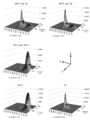
- the measurement results of the entire range of excitation wavelengths and the entire range of fluorescence wavelengths are shown in FIG.
- the X-axis direction indicates the excitation wavelength
- the Y-axis direction indicates the fluorescence wavelength
- the Z-axis direction indicates the fluorescence intensity.
- Table 16 shows the emission intensity, maximum excitation wavelength, and emission maximum wavelength of the emission peak.
- BK15 alone showed an emission peak in a low wavelength region such as 400 nm, but its intensity FI was about 15,000.
- BL alone did not show an emission peak in the low wavelength region including 400 nm, but the intensity FI in the high wavelength region showed 150,000, which is one digit larger than that of BK15.
- the FRET fluorescent protein complex in addition to the peak in the low wavelength region such as 400 nm, the peak was confirmed in the high wavelength region. Also from this result, as described in FIG. 2, when the FRET fluorescent protein complex is excited at 400 nm, the BK15 of the first fluorescent protein is excited and emits light. It can be seen that BL and Wt are excited to emit light.
- the supernatant samples of BK15-gs3-BL, BK15-gs3-Wt and BK15-gs3-BK15 prepared in Example 1 were diluted to 2 ⁇ mol / L. About 50 ⁇ L of these diluted samples, the fluorescence intensity (FI) was measured in the same manner as in Example 2 under the following measurement conditions using the microplate reader. Further, the same measurement was performed for the BK15 supernatant sample and the BL supernatant sample as negative controls.
- FI fluorescence intensity
- the fluorescence intensity was significantly increased by each FRET type fluorescent protein complex as compared with the case of BK alone and BL alone, specifically, The fluorescence intensity at the fluorescence maximum wavelength increased significantly.
- BK15 is used as the first fluorescent protein
- BL or Wt which is a fluorescent protein different from the first fluorescent protein
- the wavelengths of BK15-gs3-BL and BK15-gs3-Wt that showed the highest fluorescence intensity were shifted to the longer wavelength side than BK alone.
- the measurement results of the entire excitation wavelength range and the entire fluorescence wavelength range are shown in FIG. 5, as in FIG. 4, the X-axis direction indicates the excitation wavelength, the Y-axis direction indicates the fluorescence wavelength, and the Z-axis direction indicates the fluorescence intensity.
- Table 18 shows the maximum fluorescence intensity and the fluorescence detection wavelength indicating the fluorescence intensity.
- BK15 alone showed a light emission peak in a low wavelength region such as 400 nm, but its intensity FI was about 15,000.
- BL alone did not show an emission peak in the low wavelength region including 400 nm, but the intensity FI in the high wavelength region showed 150,000, which is one digit larger than that of BK15.
- the FRET fluorescent protein complex was able to confirm a peak in a high wavelength region in addition to a peak in a low wavelength region such as 400 nm. Also from this result, as described in FIG. 4, when the FRET fluorescent protein complex is excited at 400 nm, the BK15 of the first fluorescent protein is excited and emits light. It can be seen that BL and Wt are excited to emit light.
- Appendix 1 Including a first fluorescent protein and a second fluorescent protein, The first fluorescent protein and the second fluorescent protein are linked; The combination of the first fluorescent protein and the second fluorescent protein is a combination in which the fluorescence wavelength (L1) of the first fluorescent protein and the excitation wavelength (E2) of the second fluorescent protein overlap.
- a fluorescent protein complex characterized by the above. (Appendix 2) The second fluorescent protein is The second fluorescent protein was excited with the emission intensity (I2 E1 ) when the second fluorescent protein was excited with the excitation wavelength (E1) of the first fluorescent protein and the fluorescence wavelength (L1) of the first fluorescent protein. 2.
- the fluorescent protein complex according to appendix 1 wherein the emission intensity (I2 L1 ) satisfies the relationship of I2 E1 ⁇ I2 L1 .
- Appendix 3 The fluorescent protein complex according to appendix 1 or 2, wherein the first fluorescent protein and the second fluorescent protein are different proteins.
- Appendix 4 The fluorescent protein complex according to appendix 3, wherein the maximum excitation wavelength of the first fluorescent protein and the maximum excitation wavelength of the second fluorescent protein are different.
- Appendix 5 The fluorescent protein complex according to any one of appendices 1 to 4, wherein the fluorescence wavelength (L1) of the first fluorescent protein and the excitation wavelength (E2) of the second fluorescent protein include a wavelength of 350 to 650 nm. body.
- (Appendix 13) Irradiating the fluorescent protein complex according to any one of appendices 1 to 12 with light having an excitation wavelength of the first fluorescent protein in the fluorescent protein complex, By irradiating the first fluorescent protein with light having an excitation wavelength of the first fluorescent protein, the first fluorescent protein is caused to emit light, A method for emitting a fluorescent protein, wherein the second fluorescent protein in the fluorescent protein complex is excited by light emission of the first fluorescent protein to cause the second fluorescent protein to emit light. (Appendix 14) Furthermore, the light-emission method of Additional remark 13 including the detection process of light emission of said 2nd fluorescent protein.
- the first nucleic acid sequence and the second nucleic acid sequence are linked so as to be expressed as a complex in which the first fluorescent protein and the second fluorescent protein are linked;
- the combination of the first fluorescent protein and the second fluorescent protein is a combination in which the fluorescence wavelength (L1) of the first fluorescent protein and the excitation wavelength (E2) of the second fluorescent protein overlap.
- a gene encoding a fluorescent protein complex characterized by (Appendix 16) The gene according to appendix 15, wherein the first nucleic acid sequence and the second nucleic acid sequence are linked via a nucleic acid sequence encoding a linker.
- Appendix 17 An expression vector comprising the gene encoding the fluorescent protein complex according to appendix 15 or 16.
- Appendix 18 A transformant comprising the gene encoding the fluorescent protein complex according to appendix 15 or 16, or the expression vector according to appendix 17.
- the present invention by combining the first fluorescent protein and the fluorescent protein under the above-described conditions, for example, when the excitation light from the outside is different from the excitation conditions of the second fluorescent protein or maximum excitation Even when the wavelength deviates from the wavelength, the second fluorescent protein can emit light by excitation due to light emission of the first fluorescent protein. For this reason, according to this invention, compared with the case where a fluorescent protein is used independently, the setting of a wider optical condition is attained, for example.
Landscapes
- Chemical & Material Sciences (AREA)
- Life Sciences & Earth Sciences (AREA)
- Health & Medical Sciences (AREA)
- Genetics & Genomics (AREA)
- Engineering & Computer Science (AREA)
- Organic Chemistry (AREA)
- Bioinformatics & Cheminformatics (AREA)
- Zoology (AREA)
- Biotechnology (AREA)
- Biochemistry (AREA)
- Biomedical Technology (AREA)
- Wood Science & Technology (AREA)
- General Health & Medical Sciences (AREA)
- General Engineering & Computer Science (AREA)
- Molecular Biology (AREA)
- Biophysics (AREA)
- Microbiology (AREA)
- Physics & Mathematics (AREA)
- Plant Pathology (AREA)
- Medicinal Chemistry (AREA)
- Proteomics, Peptides & Aminoacids (AREA)
- Cell Biology (AREA)
- Peptides Or Proteins (AREA)
- Micro-Organisms Or Cultivation Processes Thereof (AREA)
Abstract
新たな蛍光タンパク質を提供する。 本発明のFRET型蛍光タンパク質複合体は、 第1蛍光タンパク質と第2蛍光タンパク質とを含み、 前記第1蛍光タンパク質と前記第2蛍光タンパク質とが連結されており、 前記第1蛍光タンパク質と前記第2蛍光タンパク質との組み合わせは、前記第1蛍光タンパク質の蛍光波長(L1)と、前記第2蛍光タンパク質の励起波長(E2)とが、重複している組み合わせであることを特徴とする。
Description
本発明は、蛍光タンパク質複合体、および蛍光タンパク質の発光方法に関する。
蛍光タンパク質として、GFP(Green Fluorescent Protein)およびYFP(Yellow Fluorescent Protein)等が、一般的に用いられている(非特許文献1)。前記蛍光タンパク質は、研究等の様々な用途に使用されている。
Chalfie M et al., "Green fluorescent protein as a marker for gene expression", Science, February 1994, Vol.263, no.5148, p802-805.
しかし、前記蛍光タンパク質は、それぞれ特有の励起波長および最大励起波長、ならびに蛍光波長および発光極大波長を有しているため、前記蛍光タンパク質を励起により発光させ、その発光を検出するには、それぞれの励起条件および発光検出条件により、光学的に使用が制限される場合がある。
そこで、本発明は、例えば、蛍光タンパク質に依存する光学的な条件を広げることができる、新たな蛍光タンパク質を提供することを目的とする。
本発明の蛍光タンパク質複合体は、
第1蛍光タンパク質と第2蛍光タンパク質とを含み、
前記第1蛍光タンパク質と前記第2蛍光タンパク質とが連結されており、
前記第1蛍光タンパク質と前記第2蛍光タンパク質との組み合わせは、前記第1蛍光タンパク質の蛍光波長(L1)と、前記第2蛍光タンパク質の励起波長(E2)とが、重複している組み合わせであることを特徴とする。
第1蛍光タンパク質と第2蛍光タンパク質とを含み、
前記第1蛍光タンパク質と前記第2蛍光タンパク質とが連結されており、
前記第1蛍光タンパク質と前記第2蛍光タンパク質との組み合わせは、前記第1蛍光タンパク質の蛍光波長(L1)と、前記第2蛍光タンパク質の励起波長(E2)とが、重複している組み合わせであることを特徴とする。
本発明の蛍光タンパク質の発光方法は、
前記本発明の蛍光タンパク質複合体に、前記蛍光タンパク質複合体における前記第1蛍光タンパク質の励起波長の光を照射する工程を含み、
前記第1蛍光タンパク質に、前記第1蛍光タンパク質の励起波長の光を照射することで、前記第1蛍光タンパク質を発光させ、
前記第1蛍光タンパク質の発光により、前記蛍光タンパク質複合体における前記第2蛍光タンパク質を励起して、前記第2蛍光タンパク質を発光させることを特徴とする。
前記本発明の蛍光タンパク質複合体に、前記蛍光タンパク質複合体における前記第1蛍光タンパク質の励起波長の光を照射する工程を含み、
前記第1蛍光タンパク質に、前記第1蛍光タンパク質の励起波長の光を照射することで、前記第1蛍光タンパク質を発光させ、
前記第1蛍光タンパク質の発光により、前記蛍光タンパク質複合体における前記第2蛍光タンパク質を励起して、前記第2蛍光タンパク質を発光させることを特徴とする。
本発明の蛍光タンパク質複合体をコードする遺伝子は、
第1蛍光タンパク質をコードする第1核酸配列と、第2蛍光タンパク質をコードする第2核酸配列とを含み、
前記第1核酸配列と前記第2核酸配列とは、前記第1蛍光タンパク質と前記第2蛍光タンパク質とが連結された複合体として発現されるように、連結されており、
前記第1蛍光タンパク質と前記第2蛍光タンパク質の組み合わせは、前記第1蛍光タンパク質の蛍光波長(L1)と、前記第2蛍光タンパク質の励起波長(E2)とが、重複している組み合わせであることを特徴とする。
第1蛍光タンパク質をコードする第1核酸配列と、第2蛍光タンパク質をコードする第2核酸配列とを含み、
前記第1核酸配列と前記第2核酸配列とは、前記第1蛍光タンパク質と前記第2蛍光タンパク質とが連結された複合体として発現されるように、連結されており、
前記第1蛍光タンパク質と前記第2蛍光タンパク質の組み合わせは、前記第1蛍光タンパク質の蛍光波長(L1)と、前記第2蛍光タンパク質の励起波長(E2)とが、重複している組み合わせであることを特徴とする。
本発明の発現ベクターは、前記本発明の蛍光タンパク質複合体をコードする遺伝子を含むことを特徴とする。
本発明の形質転換体は、前記本発明の蛍光タンパク質複合体をコードする遺伝子または前記発現ベクターを含むことを特徴とする。
本発明によれば、前記第1蛍光タンパク質と前記蛍光タンパク質とを前述の条件で組合せることにより、例えば、外部からの励起光が、前記第2蛍光タンパク質の励起条件とは異なる場合や最大励起波長から外れている場合であっても、前記第1蛍光タンパク質の発光による励起により、前記第2蛍光タンパク質を発光することができる。このため、本発明によれば、例えば、蛍光タンパク質を単独で使用する場合と比較して、より広い光学的条件の設定が可能になる。
本発明の蛍光タンパク質複合体は、例えば、前記第2蛍光タンパク質が、前記第1蛍光タンパク質の励起波長(E1)で前記第2蛍光タンパク質を励起した際の発光強度(I2E1)と、前記第1蛍光タンパク質の蛍光波長(L1)で前記第2蛍光タンパク質を励起した際の発光強度(I2L1)とが、I2E1<I2L1の関係を満たすタンパク質である。
本発明の蛍光タンパク質複合体は、例えば、前記第1蛍光タンパク質と前記第2蛍光タンパク質とが、異なるタンパク質である。
本発明の蛍光タンパク質複合体は、例えば、前記第1蛍光タンパク質の最大励起波長と前記第2蛍光タンパク質の最大励起波長とが異なる。
本発明の蛍光タンパク質複合体は、例えば、前記第1蛍光タンパク質の蛍光波長(L1)と、前記第2蛍光タンパク質の励起波長(E2)とが、350~650nmの波長を含む。
本発明の蛍光タンパク質複合体は、例えば、前記第1蛍光タンパク質の蛍光波長(L1)が、前記第2蛍光タンパク質の最大励起波長(E2max)を含む。
本発明の蛍光タンパク質複合体は、例えば、前記第2蛍光タンパク質の蛍光波長(L2)が、490~650nmの範囲を含む。
本発明の蛍光タンパク質複合体は、例えば、前記第1蛍光タンパク質と前記第2蛍光タンパク質とが、リンカーを介して連結されている。
本発明の蛍光タンパク質複合体は、例えば、前記リンカーが、ペプチドリンカーである。
本発明の蛍光タンパク質複合体は、例えば、前記ペプチドリンカーが、グリシンセリンリンカー領域を含む。
本発明の蛍光タンパク質複合体は、例えば、前記グリシンセリンリンカー領域が、配列番号48(GGGGS)のアミノ酸配列からなるペプチド単位を有する。
本発明の蛍光タンパク質複合体は、例えば、前記グリシンセリンリンカー領域が、前記ペプチド単位が1~3個連結されたリンカーである。
本発明の発光タンパク質の発光方法は、例えば、さらに、前記第2蛍光タンパク質の発光の検出工程を含む。
本発明の遺伝子は、例えば、前記第1核酸配列と前記第2核酸配列とが、リンカーをコードする核酸配列を介して連結されている。
<蛍光タンパク質複合体>
本発明の蛍光タンパク質複合体は、前述のように、
第1蛍光タンパク質と第2蛍光タンパク質とを含み、
前記第1蛍光タンパク質と前記第2蛍光タンパク質とが連結されており、
前記第1蛍光タンパク質と前記第2蛍光タンパク質との組み合わせは、前記第1蛍光タンパク質の蛍光波長(L1)と、前記第2蛍光タンパク質の励起波長(E2)とが、重複している組み合わせであることを特徴とする。
本発明の蛍光タンパク質複合体は、前述のように、
第1蛍光タンパク質と第2蛍光タンパク質とを含み、
前記第1蛍光タンパク質と前記第2蛍光タンパク質とが連結されており、
前記第1蛍光タンパク質と前記第2蛍光タンパク質との組み合わせは、前記第1蛍光タンパク質の蛍光波長(L1)と、前記第2蛍光タンパク質の励起波長(E2)とが、重複している組み合わせであることを特徴とする。
本発明の蛍光タンパク質複合体は、後述するように、前記第1蛍光タンパク質の発光により、前記第2蛍光タンパク質を励起させることから、例えば、FRET型蛍光タンパク質複合体ということもできる。なお、本発明は、いわゆる「FRET(蛍光エネルギー移動)」の機能によって限定されるものではない。
本発明において、前記第1蛍光タンパク質および前記第2蛍光タンパク質は、前述のように、前記第1蛍光タンパク質の蛍光波長(L1)と、前記第2蛍光タンパク質の励起波長(E2)とが、重複している組み合わせであればよく、その他の条件は、特に制限されない。
本発明において、「蛍光タンパク質の励起波長」とは、その蛍光タンパク質を発光できる励起光の波長をいい、「蛍光タンパク質の蛍光波長」とは、その蛍光タンパク質が励起によって発光した、前記蛍光の波長という。
本発明のFRET型蛍光タンパク質複合体によれば、例えば、目的の蛍光タンパク質の発光を、その蛍光タンパク質に特有の励起光を外部から照射しなくても、間接的に前記蛍光タンパク質の発光を生じさせることができる。すなわち、本発明のFRET型蛍光タンパク質複合体の場合、例えば、前記目的の蛍光タンパク質を前記第2蛍光タンパク質とし、前記第2蛍光タンパク質の励起波長と重複する蛍光波長の発光を示す蛍光タンパク質を前記第1蛍光タンパク質とする。このような構成とすることで、例えば、前記第2蛍光タンパク質の励起波長ではなく、前記第1蛍光タンパク質の励起波長を外部から照射することで、前記第1蛍光タンパク質を励起して発光させ、その発光により、前記第2蛍光タンパク質を間接的に励起させ、発光させることができる。
また、本発明のFRET型蛍光タンパク質複合体によれば、例えば、前記第1蛍光タンパク質または前記第2蛍光タンパク質を単独で使用する場合よりも、より強い蛍光強度の発光を得ることもできる。
本発明のFRET型蛍光タンパク質複合体において、前記第2蛍光タンパク質は、前記第1蛍光タンパク質の発光によって励起される。このため、前記第2蛍光タンパク質は、例えば、前記第1蛍光タンパク質の蛍光波長で励起されるタンパク質である。前記第2蛍光タンパク質は、前記第1蛍光タンパク質の発光によって励起され、発光できるタンパク質であればよく、例えば、前記第1蛍光タンパク質に照射される励起光によって、発光してもよいし、発光しなくてもよい。
本発明のFRET型蛍光タンパク質複合体によれば、例えば、前記第1蛍光タンパク質と前記第2蛍光タンパク質を、それぞれ単独で励起して発光させる場合と比較して、より強い発光強度の発光を得ることもできる。
本発明において、前記第2蛍光タンパク質は、例えば、前記第1蛍光タンパク質の励起波長(E1)で前記第2蛍光タンパク質を励起した際の発光強度(I2E1)と、前記第1蛍光タンパク質の蛍光波長(L1)で前記第2蛍光タンパク質を励起した際の発光強度(I2L1)とが、I2E1<I2L1の関係を満たすタンパク質があげられる。このような第2蛍光タンパク質であれば、本発明のFRET型蛍光タンパク質複合体は、例えば、前記第1タンパク質の励起波長(E1)で前記第2蛍光タンパク質を励起する場合よりも、前記第1蛍光タンパク質が発光した蛍光波長(L1)によって、間接的に前記第2蛍光タンパク質が励起され、より強い発光を示すことができる。
前記第1蛍光タンパク質の蛍光波長(L1)と、前記第2蛍光タンパク質の励起波長(E2)とは、前述のように、重複する波長を含んでいればよい。前記重複する波長は、特に制限されず、前記第1蛍光タンパク質と前記第2蛍光タンパク質の種類に応じて、適宜設定できる。
前記第1蛍光タンパク質の蛍光波長(L1)は、例えば、前記第2蛍光タンパク質の最大励起波長(E2max)を含んでもよい。この場合、本発明のFRET型蛍光タンパク質複合体において、前記第1蛍光タンパク質の発光による、前記第2蛍光タンパク質の励起で、例えば、前記第2蛍光タンパク質を、より効率よく、強い強度で発光させることができる。
前記第1蛍光タンパク質の蛍光極大波長(L1max)は、例えば、511~519nmである。
前記第2蛍光タンパク質の最大励起波長(E2max)は、例えば、501~509nm、506~514nmである。前記第2蛍光タンパク質の蛍光極大波長(L2max)は、例えば、511~519nm、516~524nmである。
前記第1蛍光タンパク質と前記第2蛍光タンパク質とは、例えば、同じタンパク質でもよいし、異なるタンパク質でもよい。前記第1蛍光タンパク質と前記第2蛍光タンパク質とが、同じ励起波長域の場合、例えば、前記励起波長域に含まれる所定の励起波長(E1)で前記第1蛍光タンパク質を励起し、前記第1蛍光タンパク質を発光させ、前記励起波長域に含まれる前記蛍光波長(L1)で前記第2蛍光タンパク質(前記第1蛍光タンパク質と同一)を励起し、発光させることができる。
前記第1蛍光タンパク質の最大励起波長(E1max)と前記第2蛍光タンパク質の最大励起波長(E2max)との差は、特に制限されない。
前記第1蛍光タンパク質の最大励起波長(E1max)は、特に制限されず、例えば、396~404nm、401~409nmの範囲である。前記第1蛍光タンパク質の励起波長(E1)は、特に制限されず、例えば、350~650nmの範囲を含む。
前記第2蛍光タンパク質の最大励起波長(E2max)は、特に制限されず、例えば、前述の通りである。前記第2蛍光タンパク質の励起波長(E2)は、特に制限されない。
前記第1蛍光タンパク質および前記第2蛍光タンパク質は、それぞれ、例えば、励起波長の変移により得られる蛍光のピークが、1つでもよいし、2つ以上でもよい。後者の場合、例えば、励起波長は、所望のピークを含む蛍光波長の発光を生じる範囲に設定することができる。
本発明のFRET型蛍光タンパク質複合体は、例えば、前記第1蛍光タンパク質と前記第2蛍光タンパク質とが、直接的に連結してもよいし、間接的に連結してもよい。後者の場合、前記第1蛍光タンパク質と前記第2蛍光タンパク質とは、例えば、リンカーを介して連結されている。
前記リンカーは、特に制限されず、例えば、前記第1蛍光タンパク質と前記第2蛍光タンパク質とが、それぞれ独立して性質を維持できればよい。前記リンカーは、例えば、ペプチドリンカーである。
前記ペプチドリンカーは、特に制限されず、例えば、グリシンセリンリンカー領域を含むペプチドリンカーがあげられる。グリシンセリンリンカーは、グリシン残基とセリン残基とを含むペプチドである。前記ペプチドリンカーは、例えば、前記グリシンセリンリンカー領域のみからなる形態でもよいし、前記グリシンセリンリンカー領域を含む形態でもよい。前記グリシンセリンリンカーは、以下、「GSリンカー」、前記グリシンセリンリンカー領域は、以下、「GSリンカー領域」ともいう。
前記グリシンセリンリンカー領域は、例えば、配列番号48(GGGGS)のアミノ酸配列からなるペプチド単位を有する。前記グリシンセリンリンカー領域において、前記ペプチド単位の個数(n)は、特に制限されず、nは、正の整数であり、例えば、1~3であり、1~2である。前記ペプチド単位を2個以上有する場合、前記グリシンセリンリンカー領域は、例えば、(GGGGS)nで表される。
前記ペプチドリンカーは、前述のように、前記グリシンセリンリンカー領域を含む形態でもよく、この場合、前記グリシンセリンリンカー領域以外の領域は、特に制限されない。本発明のFRET型蛍光タンパク質複合体を、例えば、遺伝子工学的に調製する場合、後述する本発明の発現ベクター等を用いて合成できる。前記発現ベクターは、例えば、前記第1蛍光タンパク質をコードする核酸配列と、前記第2蛍光タンパク質をコードする核酸配列と、任意で前記グリシンセリンリンカー領域をコードする核酸配列とを、制限酵素部位を利用して、骨格となるベクターに連結することで構築することができる。このため、前記ペプチドリンカーにおける前記その他の領域は、例えば、前記核酸配列を連結するための制限酵素部位に由来するペプチド領域であってもよい。前記ペプチドリンカーにおいて、前記グリシンセリンリンカー領域以外のその他の領域は、特に制限されず、例えば、その長さ(アミノ酸残基数)は、1~3、1~2である。また、前記ペプチドリンカーにおいて、前記その他の領域の位置は、特に制限されず、例えば、前記グリシンセリンリンカーのC末端側でもよいし、N末端側でもよいし、C末端側とN末端側の両方であってもよい。
前記ペプチドリンカーの長さ(アミノ酸残基数)は、特に制限されず、その下限は、例えば、1、5、8、10、13であり、その上限は、例えば、18、15、13、10、8である。
本発明のFRET型蛍光タンパク質複合体は、例えば、前記第1蛍光タンパク質の上流側に、さらに、ペプチド付加領域を有してもよい。本発明のFRET型蛍光タンパク質複合体を、例えば、遺伝子工学的に調製する場合、後述する本発明の発現ベクター等を用いて合成できる。前記発現ベクターは、例えば、前記第1蛍光タンパク質をコードする核酸配列と、前記第2蛍光タンパク質をコードする核酸配列と、任意で前記グリシンセリンリンカー領域をコードする核酸配列とを、制限酵素部位を利用して、骨格となるベクターに連結することで構築することができる。このため、例えば、前記発現ベクターに連結するための制限酵素部位に由来するペプチド領域が、前記ペプチド付加領域として付加されてもよい。前記ペプチド付加領域の長さ(アミノ酸残基数)は、特に制限されず、例えば、1~4であり、1~3であり、1~2である。
本発明のFRET型蛍光タンパク質複合体について、以下に具体例をあげるが、本発明は、これらの例には何ら制限されない。
本発明のFRET型蛍光タンパク質複合体は、前述のように、前記第1蛍光タンパク質の発光によって、前記第2蛍光タンパク質を励起し、前記第2蛍光タンパク質を発光させることができる。このため、前記第1蛍光タンパク質と前記第2蛍光タンパク質との組合せとしては、ブラックライトで励起されるタンパク質を前記第2蛍光タンパク質とし、UVライトで励起され且つブラックライトの波長域の発光を生じるタンパク質を前記第1蛍光タンパク質とする組合せが例示できる。ブラックライトで蛍光タンパク質を励起する場合、例えば、励起により発光する蛍光波長がブラックライトの波長と重複すると、発光を視覚化するために、光学フィルタを介した発光の視認が必要になる場合がある。他方、UVライトの場合、例えば、ブラックライト時のような光学フィルタを介した発光の視認を回避することができる。このため、前記第1蛍光タンパク質として、UVライトで励起され且つ励起によりブラックライト波長域に含まれる蛍光波長の発光を生じる蛍光タンパク質を第1蛍光タンパク質として使用すれば、前記第1蛍光タンパク質をUVライトで励起することにより、前記第1蛍光タンパク質を発光させることができる。そして、その発光は、ブラックライト波長域に含まれる蛍光波長であるため、この発光によって、ブラックライトを使用することなく、前記第2蛍光タンパク質を励起し、発光させることが可能となる。
このような第1蛍光タンパク質と第2蛍光タンパク質との組合せとしては、例えば、以下のような組合せが例示できる。
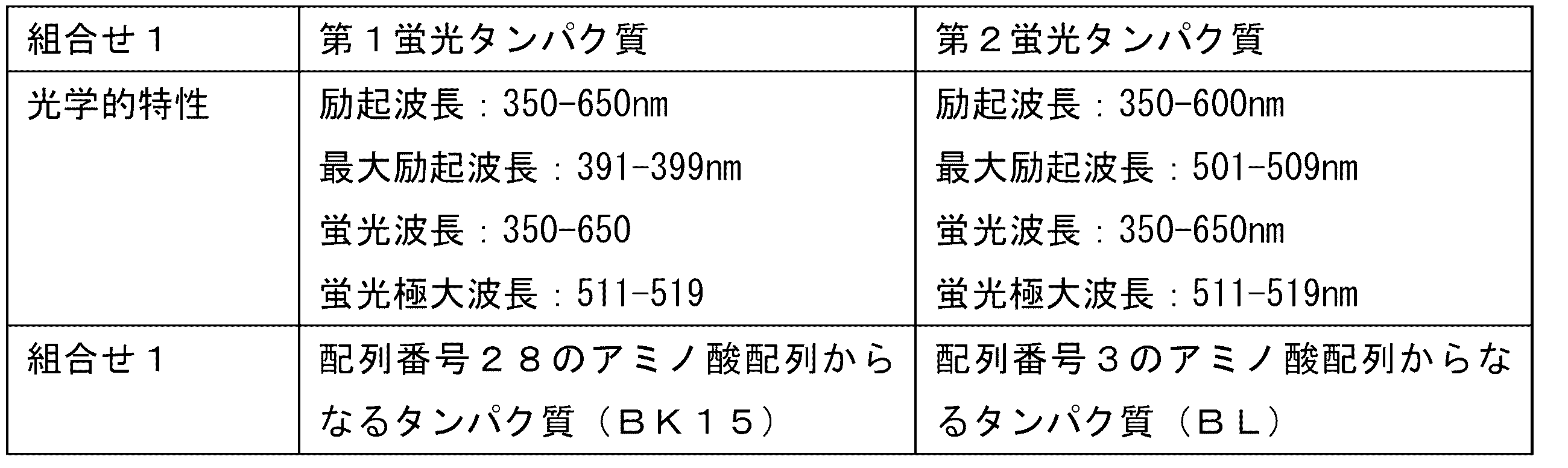
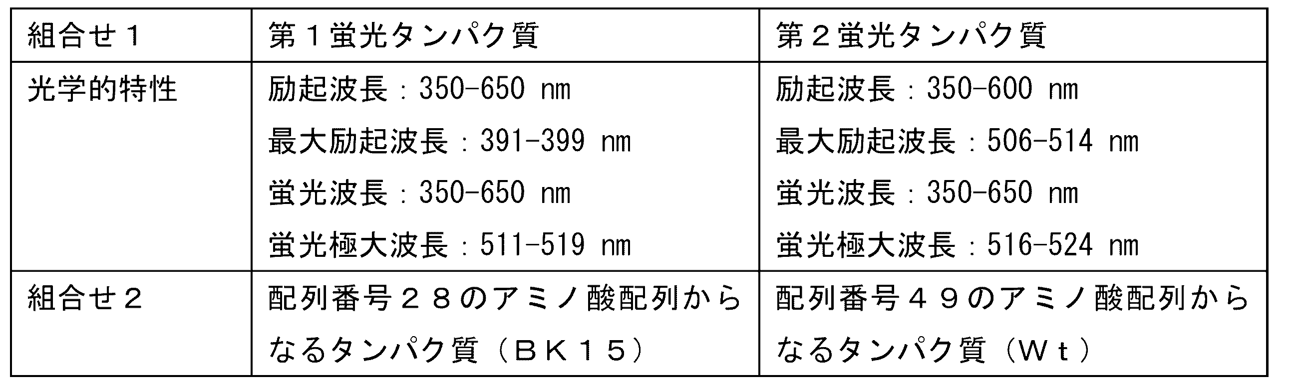
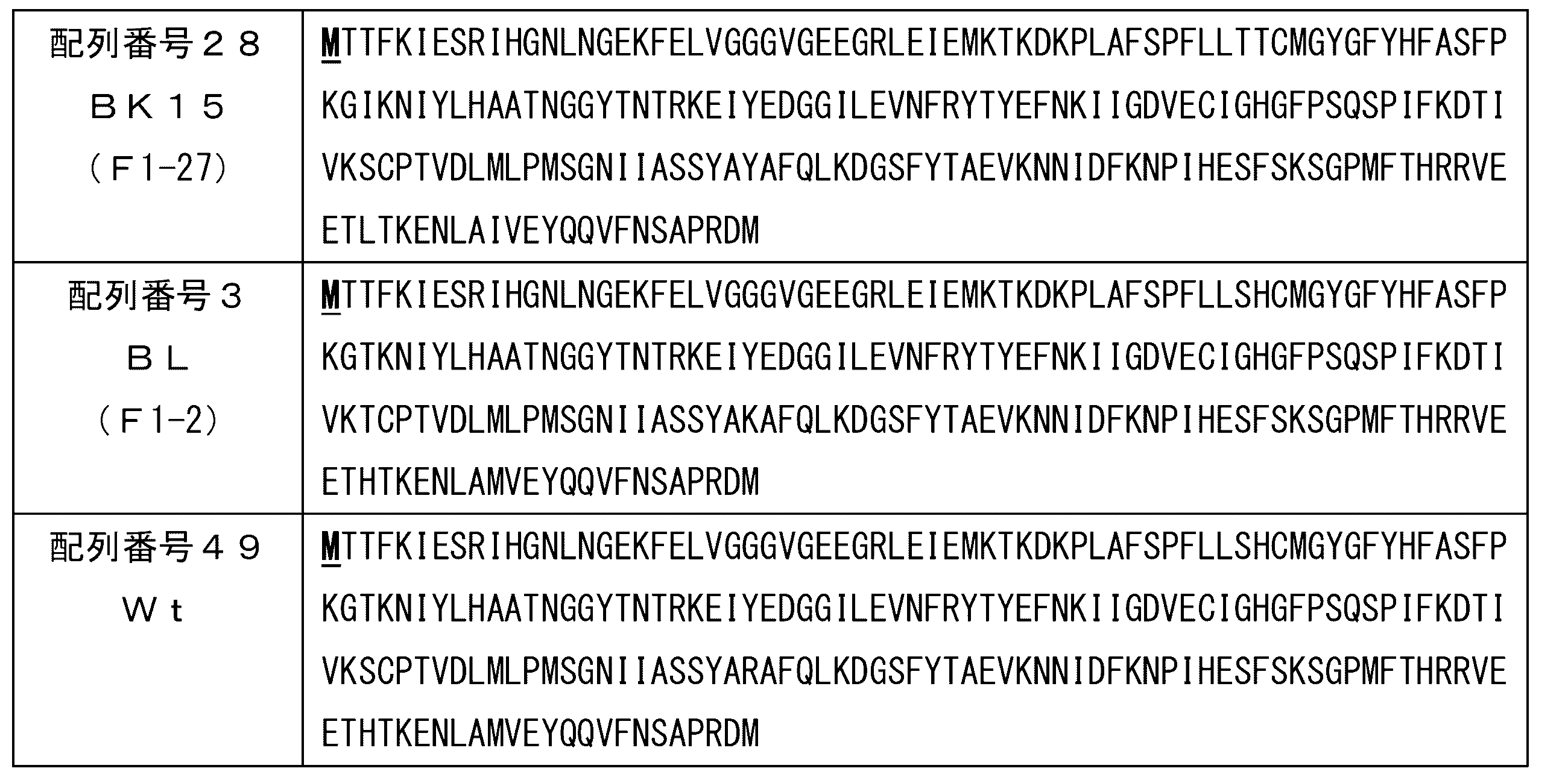
前記第1蛍光タンパク質と前記第2蛍光タンパク質は、直接的または間接的に連結されて、前記FRET型蛍光タンパク質複合体の構成要件として存在する。このため、例えば、前記FRET型蛍光タンパク質複合体を遺伝子工学的に発現させる場合、前記複合体の開始コドンは、前記第1蛍光タンパク質の1番目のメチオニン残基をコードするため、前記第2蛍光タンパク質の1番目のメチオニン残基は、欠失してもよい。
また、前記第1蛍光タンパク質、前記ペプチドリンカーにおけるグリシンセリンリンカー領域、および前記第2蛍光タンパク質の組合せとしては、例えば、以下のような組合せが例示できる。

前記表4において、前記ペプチドリンカーにおけるGSリンカー領域(GGGGS)nの繰り返し単位の数nは、特に制限されず、例えば、1~3であり、また、前記ペプチドリンカーにおけるその他の領域Nmのアミノ酸残基Nは、特に制限されず、任意のアミノ酸(Xaa)であり、例えば、全てが同じであっても異なってもよく、繰り返し単位の数mは、特に制限されず、前記ペプチド付加領域と同様である。
前記表4に示す組合せのFRET型蛍光タンパク質複合体は、例えば、以下の配列で表すことができる。
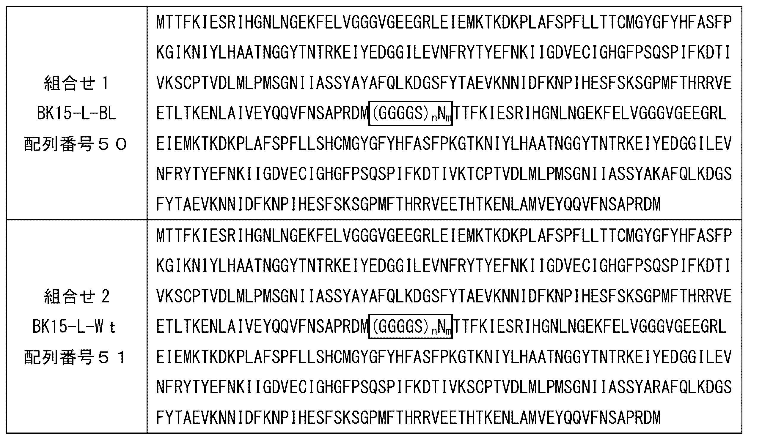
前記第1蛍光タンパク質および前記第2蛍光タンパク質は、例えば、前述の他に、以下に示す蛍光タンパク質を、組合せて使用することもできる。
(F1) 配列番号1のアミノ酸配列からなり、前記配列番号1のアミノ酸配列において、52番目のアミノ酸Xaa52が、任意のアミノ酸であり、133番目のアミノ酸Xaa133が、任意のアミノ酸であり、154番目のアミノ酸Xaa154が、任意のアミノ酸であるタンパク質
(F2) 前記(F1)の52番目のアミノ酸Xaa52、133番目のアミノ酸Xaa133、および154番目のアミノ酸Xaa154以外のアミノ酸配列において、1もしくは数個のアミノ酸が欠失、置換、挿入および/または付加されたアミノ酸配列からなり、蛍光活性を有するタンパク質
(F3) 前記(F1)の52番目のアミノ酸Xaa52、133番目のアミノ酸Xaa133、および154番目のアミノ酸Xaa154以外のアミノ酸配列に対して、80%以上の同一性を有するアミノ酸配列からなり、蛍光活性を有するタンパク質
(F2) 前記(F1)の52番目のアミノ酸Xaa52、133番目のアミノ酸Xaa133、および154番目のアミノ酸Xaa154以外のアミノ酸配列において、1もしくは数個のアミノ酸が欠失、置換、挿入および/または付加されたアミノ酸配列からなり、蛍光活性を有するタンパク質
(F3) 前記(F1)の52番目のアミノ酸Xaa52、133番目のアミノ酸Xaa133、および154番目のアミノ酸Xaa154以外のアミノ酸配列に対して、80%以上の同一性を有するアミノ酸配列からなり、蛍光活性を有するタンパク質
前記配列番号1のアミノ酸配列を有するタンパク質において、52番目、133番目、および154番目のアミノ酸は、例えば、前記タンパク質の発色団と相互作用すると推定される。前記タンパク質は、例えば、52番目、133番目、および154番目のアミノ酸を任意のアミノ酸とすることにより、前記タンパク質の蛍光活性を調整でき、例えば、相対的に低い波長の励起光(例えば、紫外線(以下同様))においても、より強い蛍光を発するタンパク質や、同一強度の励起光で励起した際に、より強い蛍光を発するタンパク質を得られる。
前記(F1)における配列番号1のアミノ酸配列は、以下の通りである。以下のアミノ酸配列において、3箇所の四角で囲んだアミノ酸(X)は、1箇所目のアミノ酸が、Xaa52、2箇所目のアミノ酸が、Xaa133、3箇所目のアミノ酸が、Xaa154に対応するアミノ酸である。また、2箇所の下線を引いたアミノ酸(X)は、1箇所目のアミノ酸が、Xaa198、2箇所目のアミノ酸が、Xaa205に対応するアミノ酸である。
(F1)

前記(F1)において、Xaa52は、任意のアミノ酸である。前記任意のアミノ酸は、A、C、D、E、F、G、H、I、K、L、M、N、P、Q、R、S、T、V、W、またはYであり、好ましくは、C、F、H、K、M、またはTであり、例えば、相対的に低い波長の励起光においても、より強い蛍光を発することから、より好ましくは、C、M、またはTである。また、前記(F1)において、Xaa52は、例えば、同一強度の励起光で励起した際に、より強い蛍光を発することから、より好ましくは、Hである。
前記(F1)において、Xaa133は、任意のアミノ酸である。前記任意のアミノ酸は、A、C、D、E、F、G、H、I、K、L、M、N、P、Q、R、S、T、V、W、またはYであり、好ましくは、L、Q、S、またはTである。また、前記(F1)において、Xaa133は、例えば、同一強度の励起光で励起した際に、より強い蛍光を発することから、より好ましくは、Tである。
前記(F1)において、Xaa154は、任意のアミノ酸である。前記任意のアミノ酸は、A、C、D、E、F、G、H、I、K、L、M、N、P、Q、R、S、T、V、W、またはYであり、好ましくは、A、H、I、K、L、Q、V、またはYであり、例えば、相対的に低い波長の励起光においても、より強い蛍光を発することから、より好ましくは、A、I、L、V、またはYである。また、前記(F1)において、Xaa154は、例えば、同一強度の励起光で励起した際に、より強い蛍光を発することから、より好ましくは、Kである。
前記(F1)において、Xaa52、Xaa133、およびXaa154の組合せは、特に制限されず、例えば、
Xaa52は、例えば、C、F、H、K、M、またはTであり、
Xaa133は、例えば、L、Q、S、またはTであり、
Xaa154は、例えば、A、H、I、K、L、Q、V、またはYである。
Xaa52は、例えば、C、F、H、K、M、またはTであり、
Xaa133は、例えば、L、Q、S、またはTであり、
Xaa154は、例えば、A、H、I、K、L、Q、V、またはYである。
前記(F1)において、Xaa52、Xaa133、およびXaa154の組合せは、例えば、相対的に低い波長の励起光においても、より強い蛍光を発することから、好ましくは、
Xaa52は、例えば、C、M、またはTであり、
Xaa133は、例えば、L、Q、S、またはTであり、
Xaa154は、例えば、A、I、L、V、またはYである。
以下、前記(F1)がこのようなXaa52、Xaa133、およびXaa154の組合せを有する場合、前記(F1)を、(B1)ともいい、前記(F2)および(F3)において、前記(F1)が(B1)の場合、前記(F2)および(F3)を、それぞれ、(B2)および(B3)ともいう。また、以下の説明において、前記(B2)および(B3)は、例えば、前記(F2)および(F3)の説明において、(F1)を(B1)に、(F2)を(B2)に、(F3)を(B3)に、それぞれ読み替えて、その説明を援用できる。
Xaa52は、例えば、C、M、またはTであり、
Xaa133は、例えば、L、Q、S、またはTであり、
Xaa154は、例えば、A、I、L、V、またはYである。
以下、前記(F1)がこのようなXaa52、Xaa133、およびXaa154の組合せを有する場合、前記(F1)を、(B1)ともいい、前記(F2)および(F3)において、前記(F1)が(B1)の場合、前記(F2)および(F3)を、それぞれ、(B2)および(B3)ともいう。また、以下の説明において、前記(B2)および(B3)は、例えば、前記(F2)および(F3)の説明において、(F1)を(B1)に、(F2)を(B2)に、(F3)を(B3)に、それぞれ読み替えて、その説明を援用できる。
前記タンパク質において、Xaa52、Xaa133、およびXaa154の組合せは、例えば、下記(aa1)~(aa11)および(aa12)のいずれか1つの組合せである。また、前記タンパク質において、Xaa52、Xaa133、およびXaa154の組合せは、例えば、相対的に低い波長の励起光においても、より強い蛍光を発することから、下記(aa1)、(aa3)、(aa6)、(aa9)、(aa10)、または(aa12)が好ましく、下記(aa1)、または(aa9)の組合せがより好ましい。また、前記タンパク質において、Xaa52、Xaa133、およびXaa154の組合せは、例えば、同一強度の励起光で励起した際に、より強い蛍光を発することから、下記(aa2)の組合せが好ましい。前記タンパク質は、例えば、Xaa52、Xaa133、およびXaa154の組合せが、それぞれ、H、SおよびRの組合せ、ならびにD、SおよびRの組合せのタンパク質を除く。
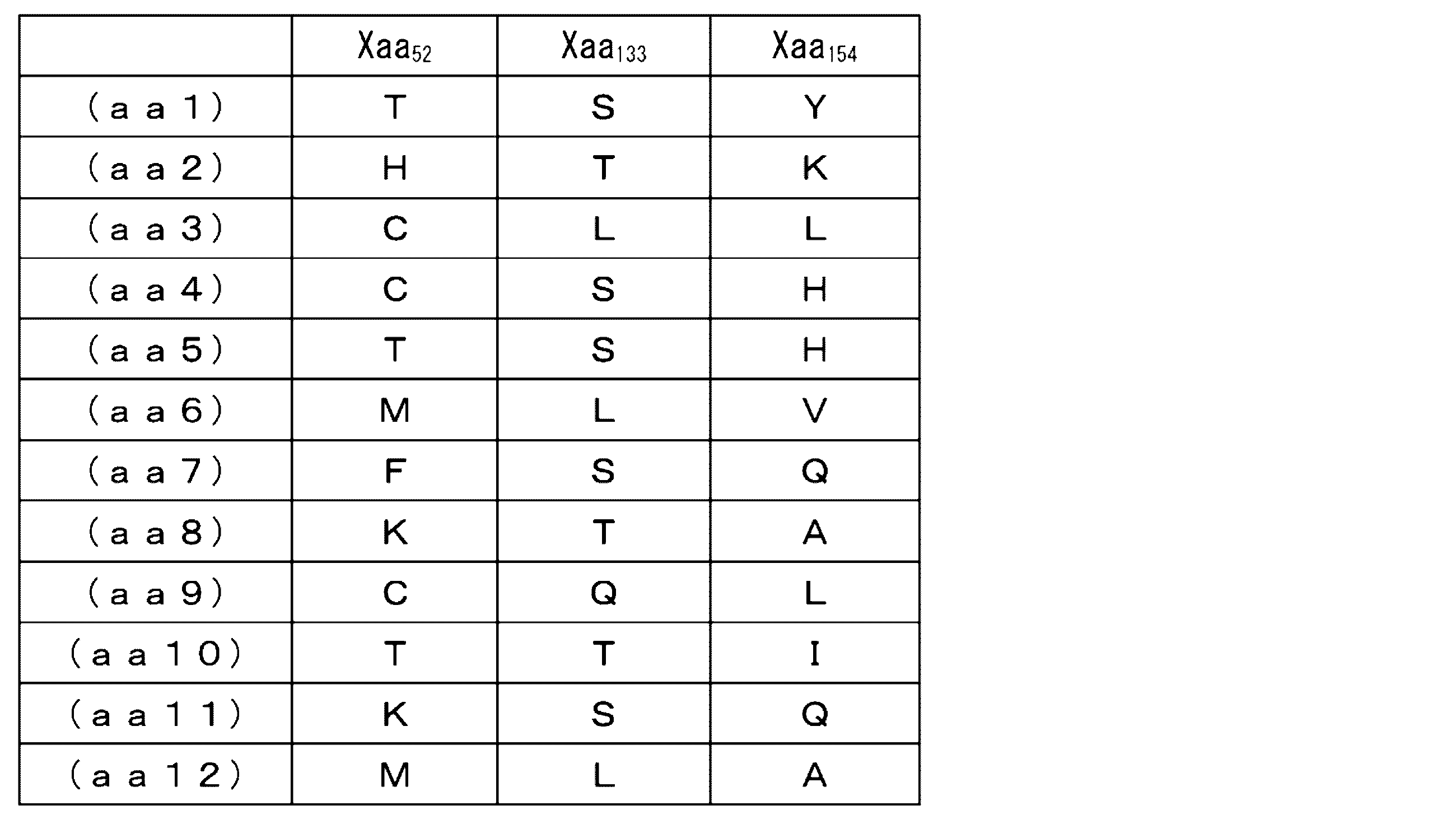
前記タンパク質において、Xaa205は、例えば、相対的に低い波長の励起光においても、より強い蛍光を発することから、Iに置換されていることが好ましい。また、前記タンパク質において、Xaa198は、例えば、相対的に低い波長の励起光においても、より強い蛍光を発することから、LまたはHに置換されていることが好ましい。前記新規タンパク質において、198番目および205番目のアミノ酸は、例えば、それぞれが、前記タンパク質の発色団と相互作用すると推定される。このため、198番目および205番目のアミノ酸の少なくとも一方について、上述の置換を行なうことにより、相対的に低い波長の励起光においても、より強い蛍光を発するタンパク質を得られると推定される。前記新規タンパク質において、Xaa198およびXaa205は、例えば、相対的に低い波長の励起光においても、さらに強い蛍光を発することから、LおよびIの組合せ、またはHおよびIの組合せに、それぞれ置換されていることがより好ましい。
前記(F1)のタンパク質は、例えば、配列番号2~47からなる群から選択された少なくとも1つのアミノ酸配列からなるタンパク質があげられる。前記(F1)が配列番号2~47のアミノ酸配列からなるタンパク質である場合、前記(F1)は、それぞれ、(F1-1)~(F1-46)ともいい、前記(F2)は、それぞれ、(F2-1)~(F2-46)ともいい、前記(F3)は、それぞれ、(F3-1)~(F3-46)ともいう。
前記(B1)のタンパク質は、例えば、配列番号2、4、7、10、11、13、および14~47からなる群から選択された少なくとも1つのアミノ酸配列からなるタンパク質があげられる。前記(B1)における各配列番号のアミノ酸配列からなるタンパク質の説明は、前記(F1)における各配列番号のアミノ酸配列からなるタンパク質の説明を援用できる。
前記(F1)における配列番号2~47のアミノ酸配列は、以下の通りである。前記配列番号2~13のアミノ酸配列は、前記配列番号1のアミノ酸配列において、Xaa52、Xaa133、およびXaa154の組合せが、それぞれ、前記(aa1)~(aa12)の組合せの場合に対応する。前記配列番号14~28のアミノ酸配列は、配列番号1のアミノ酸配列において、Xaa52、Xaa133、およびXaa154の組合せが、前記(aa1)の組合せの場合に対応する。前記配列番号29~47のアミノ酸配列は、配列番号1のアミノ酸配列において、Xaa52、Xaa133、およびXaa154の組合せが、前記(aa9)の組合せの場合に対応する。
(F1-1)

(F1-2)

(F1-3)

(F1-4)

(F1-5)

(F1-6)

(F1-7)

(F1-8)

(F1-9)

(F1-10)

(F1-11)

(F1-12)

(F1-13)

(F1-14)

(F1-15)

(F1-16)

(F1-17)

(F1-18)

(F1-19)

(F1-20)

(F1-21)

(F1-22)

(F1-23)

(F1-24)

(F1-25)

(F1-26)

(F1-27)

(F1-28)

(F1-29)

(F1-30)

(F1-31)

(F1-32)

(F1-33)

(F1-34)

(F1-35)

(F1-36)

(F1-37)

(F1-38)

(F1-39)

(F1-40)

(F1-41)

(F1-42)

(F1-43)

(F1-44)

(F1-45)

(F1-46)

前記(F2)のタンパク質は、例えば、前記(F1)のXaa52、Xaa133、およびXaa154が保存され、前記(F1)のアミノ酸配列において、1もしくは数個のアミノ酸が欠失、置換、挿入および/または付加されたアミノ酸配列からなり、蛍光活性を有するタンパク質ということもできる。前記(F2)において、「1もしくは数個」は、例えば、前記(F2)が、前記蛍光活性を有する範囲であればよい。前記(F2)のアミノ酸配列において、「1もしくは数個」は、例えば、1~43個、1~33個、1~22個、1~11個、1~9個、1~7個、1~5個、1~3個、1または2個である。本発明において、個数の数値範囲は、例えば、その範囲に属する正の整数を全て開示するものである。つまり、例えば、「1~5個」との記載は、「1、2、3、4、5個」の全ての開示を意味する(以下、同様)。前記(F1)において、Xaa205が、Iに置換されている場合、前記(F2)のタンパク質は、前記(F1)のXaa205が保存されていることが好ましい。この場合、前記(F2)のタンパク質は、例えば、前記(F1)のXaa52、Xaa133、Xaa154、およびXaa205が保存され、前記(F1)のアミノ酸配列において、1もしくは数個のアミノ酸が欠失、置換、挿入および/または付加されたアミノ酸配列からなり、蛍光活性を有するタンパク質である。また、前記(F1)において、Xaa198が、LまたはHに置換されている場合、前記(F2)のタンパク質は、前記(F1)のXaa198が保存されていることが好ましい。この場合、前記(F2)のタンパク質は、例えば、前記(F1)のXaa52、Xaa133、Xaa154、およびXaa198が保存され、前記(F1)のアミノ酸配列において、1もしくは数個のアミノ酸が欠失、置換、挿入および/または付加されたアミノ酸配列からなり、蛍光活性を有するタンパク質である。前記(F1)において、Xaa198およびXaa205が、LおよびIの組合せ、またはHおよびIの組合せに、それぞれ置換されている場合、前記(F2)のタンパク質は、前記(F1)のXaa198およびXaa205が保存されていることが好ましい。この場合、前記(F2)のタンパク質は、例えば、前記(F1)のXaa52、Xaa133、Xaa154、Xaa198、およびXaa205が保存され、前記(F1)のアミノ酸配列において、1もしくは数個のアミノ酸が欠失、置換、挿入および/または付加されたアミノ酸配列からなり、蛍光活性を有するタンパク質である。前記「1もしくは数個」は、例えば、前述の説明を援用できる。
前記(F3)のタンパク質は、前記(F1)のXaa52、Xaa133、およびXaa154が保存され、前記(F1)のアミノ酸配列に対して、80%以上の同一性を有するアミノ酸配列からなり、蛍光活性を有するタンパク質ということもできる。前記(F3)において、「同一性」は、例えば、前記(F3)が、前記蛍光活性を有する範囲であればよい。前記(F3)のアミノ酸配列において、「同一性」は、例えば、80%以上、85%以上、90%以上、95%以上、96%以上、97%以上、98%以上、99%以上である。前記「同一性」は、例えば、BLAST、FASTA等の解析ソフトウェアを用いて、デフォルトのパラメータにより算出できる(以下、同様)。前記(F1)において、Xaa205が、Iに置換されている場合、前記(F3)のタンパク質は、前記(F1)のXaa205が保存されていることが好ましい。この場合、前記(F3)のタンパク質は、例えば、前記(F1)のXaa52、Xaa133、Xaa154、およびXaa205が保存され、前記(F1)のアミノ酸配列に対して、80%以上の同一性を有するアミノ酸配列からなり、蛍光活性を有するタンパク質である。また、前記(F1)において、Xaa198が、LまたはHに置換されている場合、前記(F3)のタンパク質は、前記(F1)のXaa198が保存されていることが好ましい。この場合、前記(F3)のタンパク質は、例えば、前記(F1)のXaa52、Xaa133、Xaa154、およびXaa198が保存され、前記(F1)のアミノ酸配列に対して、80%以上の同一性を有するアミノ酸配列からなり、蛍光活性を有するタンパク質である。前記(F1)において、Xaa198およびXaa205が、LおよびIの組合せ、またはHおよびIの組合せに、それぞれ置換されている場合、前記(F3)のタンパク質は、前記(F1)のXaa198およびXaa205が保存されていることが好ましい。この場合、前記(F3)のタンパク質は、例えば、前記(F1)のXaa52、Xaa133、Xaa154、Xaa198、およびXaa205が保存され、前記(F1)のアミノ酸配列に対して、80%以上の同一性を有するアミノ酸配列からなり、蛍光活性を有するタンパク質である。前記「同一性」は、例えば、前述の説明を援用できる。
前記蛍光タンパク質は、例えば、以下のような化学的特性を有する。なお、以下で示す励起波長、励起極大波長、蛍光波長および蛍光極大波長は、例えば、350~650nmの波長の範囲における化学的特性である。
励起波長:350~650nm
励起極大波長:386~514nm
蛍光波長:350~650nm
蛍光極大波長:506~524nm
励起波長:350~650nm
励起極大波長:386~514nm
蛍光波長:350~650nm
蛍光極大波長:506~524nm
前記(F1-1)~(F1-46)のタンパク質は、例えば、それぞれ、以下のような化学的特性を有する。なお、前記(F1-1)~(F1-46)の励起波長または蛍光波長において、複数の蛍光強度の極大値が存在する場合、複数の励起極大波長および蛍光極大波長を示している。
(F1-1)
励起波長:350~560nm
励起極大波長:396~404nm
蛍光波長:350~650nm
蛍光極大波長:511~519nm
励起波長:350~560nm
励起極大波長:396~404nm
蛍光波長:350~650nm
蛍光極大波長:511~519nm
(F1-2)
励起波長:350~600nm
励起極大波長:501~509nm
蛍光波長:350~650nm
蛍光極大波長:511~519nm
励起波長:350~600nm
励起極大波長:501~509nm
蛍光波長:350~650nm
蛍光極大波長:511~519nm
(F1-3)
励起波長:350~620nm
励起極大波長:396~404nm、506~514nm
蛍光波長:350~650nm
蛍光極大波長:516~524nm
励起波長:350~620nm
励起極大波長:396~404nm、506~514nm
蛍光波長:350~650nm
蛍光極大波長:516~524nm
(F1-4)
励起波長:350~625nm
励起極大波長:496~504nm
蛍光波長:350~650nm
蛍光極大波長:511~519nm
励起波長:350~625nm
励起極大波長:496~504nm
蛍光波長:350~650nm
蛍光極大波長:511~519nm
(F1-5)
励起波長:350~615nm
励起極大波長:501~509nm
蛍光波長:350~650nm
蛍光極大波長:511~519nm
励起波長:350~615nm
励起極大波長:501~509nm
蛍光波長:350~650nm
蛍光極大波長:511~519nm
(F1-6)
励起波長:350~625nm
励起極大波長:391~399nm、506~514nm
蛍光波長:350~650nm
蛍光極大波長:516~524nm
励起波長:350~625nm
励起極大波長:391~399nm、506~514nm
蛍光波長:350~650nm
蛍光極大波長:516~524nm
(F1-7)
励起波長:350~625nm
励起極大波長:476~484nm
蛍光波長:350~650nm
蛍光極大波長:506~514nm
励起波長:350~625nm
励起極大波長:476~484nm
蛍光波長:350~650nm
蛍光極大波長:506~514nm
(F1-8)
励起波長:350~605nm
励起極大波長:496~504nm
蛍光波長:350~650nm
蛍光極大波長:511~519nm
励起波長:350~605nm
励起極大波長:496~504nm
蛍光波長:350~650nm
蛍光極大波長:511~519nm
(F1-9)
励起波長:350~615nm
励起極大波長:401~409nm、496~504nm
蛍光波長:350~650nm
蛍光極大波長:511~519nm
励起波長:350~615nm
励起極大波長:401~409nm、496~504nm
蛍光波長:350~650nm
蛍光極大波長:511~519nm
(F1-10)
励起波長:350~590nm
励起極大波長:391~399nm、506~514nm
蛍光波長:350~650nm
蛍光極大波長:516~524nm
励起波長:350~590nm
励起極大波長:391~399nm、506~514nm
蛍光波長:350~650nm
蛍光極大波長:516~524nm
(F1-11)
励起波長:350~575nm
励起極大波長:476~484nm
蛍光波長:350~650nm
蛍光極大波長:506~514nm
励起波長:350~575nm
励起極大波長:476~484nm
蛍光波長:350~650nm
蛍光極大波長:506~514nm
(F1-12)
励起波長:350~595nm
励起極大波長:386~394nm、506~514nm
蛍光波長:350~650nm
蛍光極大波長:516~524nm
励起波長:350~595nm
励起極大波長:386~394nm、506~514nm
蛍光波長:350~650nm
蛍光極大波長:516~524nm
(F1-13)
励起波長:350~650nm
励起極大波長:396~404nm
蛍光波長:350~650nm
蛍光極大波長:511~519nm
励起波長:350~650nm
励起極大波長:396~404nm
蛍光波長:350~650nm
蛍光極大波長:511~519nm
(F1-14)
励起波長:350~650nm
励起極大波長:401~409nm
蛍光波長:350~650nm
蛍光極大波長:511~519nm
励起波長:350~650nm
励起極大波長:401~409nm
蛍光波長:350~650nm
蛍光極大波長:511~519nm
(F1-15)
励起波長:350~650nm
励起極大波長:396~404nm
蛍光波長:350~650nm
蛍光極大波長:511~519nm
励起波長:350~650nm
励起極大波長:396~404nm
蛍光波長:350~650nm
蛍光極大波長:511~519nm
(F1-16)
励起波長:350~650nm
励起極大波長:391~399nm
蛍光波長:350~650nm
蛍光極大波長:511~519nm
励起波長:350~650nm
励起極大波長:391~399nm
蛍光波長:350~650nm
蛍光極大波長:511~519nm
(F1-17)
励起波長:350~650nm
励起極大波長:396~404nm
蛍光波長:350~650nm
蛍光極大波長:511~519nm
励起波長:350~650nm
励起極大波長:396~404nm
蛍光波長:350~650nm
蛍光極大波長:511~519nm
(F1-18)
励起波長:350~650nm
励起極大波長:396~404nm
蛍光波長:350~650nm
蛍光極大波長:511~519nm
励起波長:350~650nm
励起極大波長:396~404nm
蛍光波長:350~650nm
蛍光極大波長:511~519nm
(F1-19)
励起波長:350~650nm
励起極大波長:396~404nm
蛍光波長:350~650nm
蛍光極大波長:511~519nm
励起波長:350~650nm
励起極大波長:396~404nm
蛍光波長:350~650nm
蛍光極大波長:511~519nm
(F1-20)
励起波長:350~650nm
励起極大波長:391~399nm
蛍光波長:350~650nm
蛍光極大波長:511~519nm
励起波長:350~650nm
励起極大波長:391~399nm
蛍光波長:350~650nm
蛍光極大波長:511~519nm
(F1-21)
励起波長:350~650nm
励起極大波長:391~399nm
蛍光波長:350~650nm
蛍光極大波長:511~519nm
励起波長:350~650nm
励起極大波長:391~399nm
蛍光波長:350~650nm
蛍光極大波長:511~519nm
(F1-22)
励起波長:350~650nm
励起極大波長:396~404nm
蛍光波長:350~650nm
蛍光極大波長:511~519nm
励起波長:350~650nm
励起極大波長:396~404nm
蛍光波長:350~650nm
蛍光極大波長:511~519nm
(F1-23)
励起波長:350~650nm
励起極大波長:391~399nm
蛍光波長:350~650nm
蛍光極大波長:511~519nm
励起波長:350~650nm
励起極大波長:391~399nm
蛍光波長:350~650nm
蛍光極大波長:511~519nm
(F1-24)
励起波長:350~645nm
励起極大波長:396~404nm
蛍光波長:350~650nm
蛍光極大波長:511~519nm
励起波長:350~645nm
励起極大波長:396~404nm
蛍光波長:350~650nm
蛍光極大波長:511~519nm
(F1-25)
励起波長:350~580nm
励起極大波長:396~404nm
蛍光波長:350~650nm
蛍光極大波長:511~519nm
励起波長:350~580nm
励起極大波長:396~404nm
蛍光波長:350~650nm
蛍光極大波長:511~519nm
(F1-26)
励起波長:350~560nm
励起極大波長:396~404nm
蛍光波長:350~650nm
蛍光極大波長:511~519nm
励起波長:350~560nm
励起極大波長:396~404nm
蛍光波長:350~650nm
蛍光極大波長:511~519nm
(F1-27)
励起波長:350~650nm
励起極大波長:391~399nm
蛍光波長:350~650nm
蛍光極大波長:511~519nm
励起波長:350~650nm
励起極大波長:391~399nm
蛍光波長:350~650nm
蛍光極大波長:511~519nm
(F1-28)
励起波長:350~650nm
励起極大波長:401~409nm、496~504nm
蛍光波長:350~650nm
蛍光極大波長:511~519nm
励起波長:350~650nm
励起極大波長:401~409nm、496~504nm
蛍光波長:350~650nm
蛍光極大波長:511~519nm
(F1-29)
励起波長:350~650nm
励起極大波長:401~409nm、496~504nm
蛍光波長:350~650nm
蛍光極大波長:511~519nm
励起波長:350~650nm
励起極大波長:401~409nm、496~504nm
蛍光波長:350~650nm
蛍光極大波長:511~519nm
(F1-30)
励起波長:350~650nm
励起極大波長:401~409nm、496~504nm
蛍光波長:350~650nm
蛍光極大波長:511~519nm
励起波長:350~650nm
励起極大波長:401~409nm、496~504nm
蛍光波長:350~650nm
蛍光極大波長:511~519nm
(F1-31)
励起波長:350~650nm
励起極大波長:401~409nm、496~504nm
蛍光波長:350~650nm
蛍光極大波長:511~519nm
励起波長:350~650nm
励起極大波長:401~409nm、496~504nm
蛍光波長:350~650nm
蛍光極大波長:511~519nm
(F1-32)
励起波長:350~650nm
励起極大波長:401~409nm、496~504nm
蛍光波長:350~650nm
蛍光極大波長:511~519nm
励起波長:350~650nm
励起極大波長:401~409nm、496~504nm
蛍光波長:350~650nm
蛍光極大波長:511~519nm
(F1-33)
励起波長:350~650nm
励起極大波長:401~409nm、496~504nm
蛍光波長:350~650nm
蛍光極大波長:511~519nm
励起波長:350~650nm
励起極大波長:401~409nm、496~504nm
蛍光波長:350~650nm
蛍光極大波長:511~519nm
(F1-34)
励起波長:350~650nm
励起極大波長:401~409nm、496~504nm
蛍光波長:350~650nm
蛍光極大波長:511~519nm
励起波長:350~650nm
励起極大波長:401~409nm、496~504nm
蛍光波長:350~650nm
蛍光極大波長:511~519nm
(F1-35)
励起波長:350~650nm
励起極大波長:406~414nm、496~504nm
蛍光波長:350~650nm
蛍光極大波長:511~519nm
励起波長:350~650nm
励起極大波長:406~414nm、496~504nm
蛍光波長:350~650nm
蛍光極大波長:511~519nm
(F1-36)
励起波長:350~650nm
励起極大波長:401~409nm、501~509nm
蛍光波長:350~650nm
蛍光極大波長:511~519nm
励起波長:350~650nm
励起極大波長:401~409nm、501~509nm
蛍光波長:350~650nm
蛍光極大波長:511~519nm
(F1-37)
励起波長:350~650nm
励起極大波長:401~409nm、496~504nm
蛍光波長:350~650nm
蛍光極大波長:511~519nm
励起波長:350~650nm
励起極大波長:401~409nm、496~504nm
蛍光波長:350~650nm
蛍光極大波長:511~519nm
(F1-38)
励起波長:350~650nm
励起極大波長:401~409nm、496~504nm
蛍光波長:350~650nm
蛍光極大波長:511~519nm
励起波長:350~650nm
励起極大波長:401~409nm、496~504nm
蛍光波長:350~650nm
蛍光極大波長:511~519nm
(F1-39)
励起波長:350~650nm
励起極大波長:416~424nm、496~504nm
蛍光波長:350~650nm
蛍光極大波長:511~519nm
励起波長:350~650nm
励起極大波長:416~424nm、496~504nm
蛍光波長:350~650nm
蛍光極大波長:511~519nm
(F1-40)
励起波長:350~650nm
励起極大波長:401~409nm、496~504nm
蛍光波長:350~650nm
蛍光極大波長:511~519nm
励起波長:350~650nm
励起極大波長:401~409nm、496~504nm
蛍光波長:350~650nm
蛍光極大波長:511~519nm
(F1-41)
励起波長:350~650nm
励起極大波長:401~409nm、496~504nm
蛍光波長:350~650nm
蛍光極大波長:511~519nm
励起波長:350~650nm
励起極大波長:401~409nm、496~504nm
蛍光波長:350~650nm
蛍光極大波長:511~519nm
(F1-42)
励起波長:350~650nm
励起極大波長:416~424nm、496~504nm
蛍光波長:350~650nm
蛍光極大波長:511~519nm
励起波長:350~650nm
励起極大波長:416~424nm、496~504nm
蛍光波長:350~650nm
蛍光極大波長:511~519nm
(F1-43)
励起波長:350~650nm
励起極大波長:421~429nm、501~509nm
蛍光波長:350~650nm
蛍光極大波長:511~519nm
励起波長:350~650nm
励起極大波長:421~429nm、501~509nm
蛍光波長:350~650nm
蛍光極大波長:511~519nm
(F1-44)
励起波長:350~650nm
励起極大波長:401~409nm、496~504nm
蛍光波長:350~650nm
蛍光極大波長:511~519nm
励起波長:350~650nm
励起極大波長:401~409nm、496~504nm
蛍光波長:350~650nm
蛍光極大波長:511~519nm
(F1-45)
励起波長:350~650nm
励起極大波長:401~409nm、496~504nm
蛍光波長:350~650nm
蛍光極大波長:511~519nm
励起波長:350~650nm
励起極大波長:401~409nm、496~504nm
蛍光波長:350~650nm
蛍光極大波長:511~519nm
(F1-46)
励起波長:350~650nm
励起極大波長:401~409nm、496~504nm
蛍光波長:350~650nm
蛍光極大波長:511~519nm
励起波長:350~650nm
励起極大波長:401~409nm、496~504nm
蛍光波長:350~650nm
蛍光極大波長:511~519nm
前記励起波長、前記励起極大波長、前記蛍光波長、および前記蛍光極大波長の測定方法は、特に制限されず、例えば、JIS K0120に基づいて行うことができる。
<蛍光タンパク質の発光方法>
本発明の蛍光タンパク質の発光方法は、前述のように、前記本発明のFRET型蛍光タンパク質複合体に、前記FRET型蛍光タンパク質複合体における前記第1蛍光タンパク質の励起波長の光を照射する工程を含み、
前記第1蛍光タンパク質に、前記第1蛍光タンパク質の励起波長の光を照射することで、前記第1蛍光タンパク質を発光させ、
前記第1蛍光タンパク質の発光により、前記FRET型蛍光タンパク質複合体における前記第2蛍光タンパク質を励起して、前記第2蛍光タンパク質を発光させることを特徴とする。
本発明の蛍光タンパク質の発光方法は、前述のように、前記本発明のFRET型蛍光タンパク質複合体に、前記FRET型蛍光タンパク質複合体における前記第1蛍光タンパク質の励起波長の光を照射する工程を含み、
前記第1蛍光タンパク質に、前記第1蛍光タンパク質の励起波長の光を照射することで、前記第1蛍光タンパク質を発光させ、
前記第1蛍光タンパク質の発光により、前記FRET型蛍光タンパク質複合体における前記第2蛍光タンパク質を励起して、前記第2蛍光タンパク質を発光させることを特徴とする。
本発明の発光方法は、前記本発明のFRET型蛍光タンパク質複合体を使用し、前記FRET型蛍光タンパク質複合体における前記第1蛍光タンパク質に対して、前記第1蛍光タンパク質が発光する条件の励起光を照射し、前記第1蛍光タンパク質の発光により、前記第2蛍光タンパク質を発光させればよく、その他の構成は、何ら制限されない。
前記照射工程において、前記FRET型蛍光タンパク質複合体に照射する光の波長は、特に制限されず、前記第1蛍光タンパク質の励起波長であり、且つ、励起による前記第1蛍光タンパク質の発光が、前記第2蛍光タンパク質の励起波長を含む条件であればよい。前記第1蛍光タンパク質の励起波長および蛍光波長、ならびに前記第2蛍光タンパク質の励起波長および蛍光波長は、例えば、本発明のFRET型蛍光タンパク質複合体の記載を援用できる。
本発明の発光方法は、例えば、さらに、前記第2蛍光タンパク質の発光を検出する検出工程を含んでもよい。この場合、本発明の発光方法は、例えば、本発明の発光の検出方法ということもできる。
本発明のFRET型蛍光タンパク質複合体において例示した前記表1、表2、表3、および表5の組合せの場合、例えば、以下のような、励起と蛍光検出が可能となる。なお、本発明は、これには制限されない。
前記FRET型蛍光タンパク質複合体の場合、前記第1蛍光タンパク質は、例えば、UVライトの波長域の照射光により励起が可能である。そして、前記照射光の励起による前記第1蛍光タンパク質の発光は、前記第2蛍光タンパク質の励起波長を含むため、これにより前記第2蛍光タンパク質を発光させ、前記発光を検出することができる。前記第2蛍光タンパク質を単体で使用する場合、例示した前記第2蛍光タンパク質の励起波長がブラックライトの波長域であると、例えば、ブラックライトの照射光が照射される。しかし、前記第2蛍光タンパク質の発光が、前記ブラックライトの波長と重複すると、前記第2蛍光タンパク質の発光を、直接視認することができず、発光以外の光をカットする光学フィルタ(例えば、商品名SC-52、富士フィルム社製)を介して、視認する必要がある。しかしながら、前記FRET型蛍光タンパク質複合体の場合、外部からの励起光は、前記第1蛍光タンパク質に応じて設定でき、前記第2蛍光タンパク質は、前記第1蛍光タンパク質の発光により励起されるため、前述のような前記ブラックライトの使用による問題も解消できる。また、前記FRET型蛍光タンパク質複合体の場合、前記第2蛍光タンパク質を単独で使用する場合よりも、例えば、より強い蛍光強度の発光を得ることもできる。
<遺伝子>
本発明の遺伝子は、前述のように、FRET型蛍光タンパク質複合体をコードする遺伝子であり、第1蛍光タンパク質をコードする第1核酸配列と、第2蛍光タンパク質をコードする第2核酸配列とを含み、前記第1核酸配列と前記第2核酸配列とは、前記第1蛍光タンパク質と前記第2蛍光タンパク質とが連結された複合体として発現されるように、連結されており、前記第1蛍光タンパク質と前記第2蛍光タンパク質の組み合わせは、前記第1蛍光タンパク質の蛍光波長(L1)と、前記第2蛍光タンパク質の励起波長(E2)とが、重複している組み合わせであることを特徴とする。本発明の遺伝子によれば、例えば、これを発現させることで、前記本発明のFRET型蛍光タンパク質複合体を容易に製造できる。
本発明の遺伝子は、前述のように、FRET型蛍光タンパク質複合体をコードする遺伝子であり、第1蛍光タンパク質をコードする第1核酸配列と、第2蛍光タンパク質をコードする第2核酸配列とを含み、前記第1核酸配列と前記第2核酸配列とは、前記第1蛍光タンパク質と前記第2蛍光タンパク質とが連結された複合体として発現されるように、連結されており、前記第1蛍光タンパク質と前記第2蛍光タンパク質の組み合わせは、前記第1蛍光タンパク質の蛍光波長(L1)と、前記第2蛍光タンパク質の励起波長(E2)とが、重複している組み合わせであることを特徴とする。本発明の遺伝子によれば、例えば、これを発現させることで、前記本発明のFRET型蛍光タンパク質複合体を容易に製造できる。
本発明の遺伝子は、例えば、前記第1核酸配列と前記第2蛍光タンパク質とが、リンカーをコードする核酸配列を介して連結されている。
本発明の遺伝子は、前記本発明のFRET型蛍光タンパク質複合体をコードすればよく、その他の構成等は何ら制限されない。本発明の遺伝子は、例えば、前記第1蛍光タンパク質、前記第2蛍光タンパク質、および任意の前記リンカーのアミノ酸配列に応じて、適宜、それらをコードするコドンからなる核酸配列に置き換えることで設計できる。
本発明の遺伝子を構成するポリヌクレオチドは、例えば、公知の遺伝子工学的手法または合成手法によって製造できる。
<発現ベクター>
本発明の発現ベクターは、前述のように、前記本発明のFRET型蛍光タンパク質複合体をコードする遺伝子を含むことを特徴とする。本発明の発現ベクターによれば、例えば、前記発現ベクターを宿主に導入することで、前記本発明のFRET型蛍光タンパク質複合体を容易に製造できる。本発明の発現ベクターは、例えば、前記本発明の遺伝子の説明等を援用できる。
本発明の発現ベクターは、前述のように、前記本発明のFRET型蛍光タンパク質複合体をコードする遺伝子を含むことを特徴とする。本発明の発現ベクターによれば、例えば、前記発現ベクターを宿主に導入することで、前記本発明のFRET型蛍光タンパク質複合体を容易に製造できる。本発明の発現ベクターは、例えば、前記本発明の遺伝子の説明等を援用できる。
前記発現ベクターは、例えば、前記本発明の遺伝子がコードする前記FRET型蛍光タンパク質複合体を発現可能なように、機能的に、前記遺伝子を構成するポリヌクレオチドを含んでいればよく、その他の構成は、特に制限されない。
前記発現ベクターは、例えば、骨格となるベクター(以下、「基本ベクター」ともいう。)に、前記ポリヌクレオチドを挿入することで作製できる。前記ベクターの種類は、特に制限されず、例えば、前記宿主の種類に応じて、適宜決定できる。前記ベクターは、ウイルスベクターおよび非ウイルスベクターがあげられる。前記ベクターは、例えば、バイナリーベクターが好ましい。植物に形質転換を行う場合、前記ベクターは、T-DNA型バイナリーベクターが好ましい。アグロバクテリウムを使用する方法により、植物に形質転換を行う場合、前記ベクターは、例えば、pBI121ベクター、pPZP202ベクター、pBINPLUSベクター、pBIN19ベクター、pBIG2113N、pBIG2113SF、pRI101DNAベクター(TaKaRa社製)、pRI201DNAベクター(TaKaRa社製)、pRI909DNAベクター(TaKaRa社製)、pRI910DNAベクター(TaKaRa社製)等があげられる。大腸菌等の微生物に形質転換を行う場合、前記ベクターは、例えば、pETDuet-1ベクター(ノバジェン社)、pQE-80Lベクター(QIAGEN社)、pBluescript II SKベクター、pET101/D-TOPOベクター(Invitrogen社製)、pGEX-6P-1ベクター(Amersham Biosciences社製)、pcDNA3.2/V5-GW/D-TOPOベクター(Invitrogen社製)、pEGFPベクター、pcDNA3.1-hygro(-)ベクター(Invitrogen社製)等があげられる。
前記発現ベクターは、例えば、前記ポリヌクレオチドの発現および前記ポリヌクレオチドがコードする前記本発明のFRET型蛍光タンパク質複合体の発現を調節する、調節配列を有することが好ましい。前記調節配列は、例えば、プロモーター、ターミネーター、エンハンサー、ポリアデニル化シグナル配列、複製起点配列(ori)等があげられる。前記発現ベクターにおいて、前記調節配列の配置は特に制限されない。前記発現ベクターにおいて、前記調節配列は、例えば、前記ポリヌクレオチドの発現およびこれがコードする前記FRET型蛍光タンパク質複合体の発現を、機能的に調節できるように配置されていればよく、公知の方法に基づいて配置できる。前記調節配列は、例えば、前記基本ベクターが予め備える配列を利用してもよいし、前記基本ベクターに、さらに、前記調節配列を挿入してもよいし、前記基本ベクターが備える調節配列を、他の調節配列に置き換えてもよい。
前記発現ベクターは、例えば、さらに、選択マーカーのコード配列を有してもよい。前記選択マーカーは、例えば、薬剤耐性マーカー、蛍光タンパク質マーカー、酵素マーカー、細胞表面レセプターマーカー等があげられる。
<FRET型蛍光タンパク質複合体の製造方法>
本発明のFRET型蛍光タンパク質複合体の製造方法は、特に制限されず、例えば、遺伝子工学的手法により製造してもよいし、公知の合成方法により製造してもよい。前者の場合、本発明の製造方法は、前記本発明の遺伝子を発現させる発現工程を含む。これにより、本発明のFRET型蛍光タンパク質複合体の製造方法は、例えば、前記本発明のFRET型蛍光タンパク質複合体を容易に製造できる。
本発明のFRET型蛍光タンパク質複合体の製造方法は、特に制限されず、例えば、遺伝子工学的手法により製造してもよいし、公知の合成方法により製造してもよい。前者の場合、本発明の製造方法は、前記本発明の遺伝子を発現させる発現工程を含む。これにより、本発明のFRET型蛍光タンパク質複合体の製造方法は、例えば、前記本発明のFRET型蛍光タンパク質複合体を容易に製造できる。
前記本発明の遺伝子の発現は、例えば、前記遺伝子を構成するポリヌクレオチドの発現であり、前記本発明の発現ベクターを使用して行ってもよい。
前記ポリヌクレオチドを発現させる方法は、特に制限されず、公知の方法が採用でき、例えば、無細胞タンパク質合成系を使用してもよいし、宿主を使用してもよい。
前者の場合、無細胞タンパク質合成系において前記ポリヌクレオチドを発現させることが好ましい。この場合、前記ポリヌクレオチドの発現には、発現ベクターを使用してもよい。前記無細胞タンパク質合成系は、例えば、細胞抽出液と、各種成分を含むバッファーと、目的のポリヌクレオチドが導入された発現ベクターとを用いて、公知の方法により行うことができ、例えば、市販の試薬キットが使用できる。
後者の場合、例えば、前記ポリヌクレオチドが導入された前記宿主を使用し、前記宿主の培養により、前記宿主において前記ポリヌクレオチドを発現させることが好ましい。このように、例えば、前記ポリヌクレオチドを宿主に導入することで、本発明のFRET型蛍光タンパク質複合体を合成する形質転換体を製造でき、また、前記形質転換体の培養により、本発明のFRET型蛍光タンパク質複合体を合成できる。
前記宿主は、例えば、微生物、植物、動物、昆虫またはこれらの培養細胞等の非ヒト宿主、単離したヒト細胞またはその培養細胞等があげられ、好ましくは、植物である。前記宿主が植物の場合、前記植物は、例えば、植物体またはその部分であってもよい。前記植物体の部分は、例えば、器官、組織、細胞または栄養繁殖体等があげられる。前記器官は、例えば、花弁、花冠、花、葉、種子、果実、茎、根等があげられる。前記組織は、例えば、前記器官の部分である。前記細胞は、例えば、前記植物体またはその組織から採取した細胞、前記細胞の培養細胞、プロトプラスト、カルス等があげられる。前記植物の由来は、特に制限されず、例えば、アブラナ科、ナス科、イネ科、マメ科、バラ科、ナデシコ科、キク科、リンドウ科、ゴマノハグサ科、クマツヅラ科、サクラソウ科、サボテン科、ラン科等があげられる。前記アブラナ科は、例えば、シロイヌナズナ(Arabidopsis thaliana)等のシロイヌナズナ属等があげられる。前記ナス科は、例えば、タバコ(Nicotiana tabacum)等のタバコ属、ペチュニア(Petunia×hybrida)等のツクバネアサガオ属(Petunia)、ニーレンベルギア(Nierembergia hippoamanica)等のアマモドキ属、カリブラコア(Calibrachoa hybrid Cultivar)等のカリブラコア属等があげられる。前記イネ科は、例えば、トウモロコシ(Zea mays)等のトウモロコシ属、イネ(Oryza sativa)等のイネ属等があげられる。前記マメ科は、例えば、ダイズ(Glycine max)等のダイズ属等があげられる。前記バラ科は、例えば、バラ(Rosa)等のバラ属があげられる。前記ナデシコ科は、例えば、カーネーション(Dianthus caryophyllus)等のナデシコ属等があげられる。前記キク科は、例えば、栽培ギク(Chrysantemum morifolium)等のキク属、ガーベラ(Gerbera cvs.)等のガーベラ(オオセンボンヤリ)属等があげられる。前記リンドウ科は、例えば、トルコキキョウ(Eustoma grandiflorum)等のユーストマ属等があげられる。前記ゴマノハグサ科は、例えば、トレニア(Torenia fournieri)等のトレニア属等があげられる。前記クマツヅラ科は、例えば、バーベナ(Garden verbena)等のバーベナ属等があげられる。前記サクラソウ科は、例えば、シクラメン(Cyclamen persicum)等のシクラメン属等があげられる。前記サボテン科は、例えば、アウストロキリンドロプンティア属、アストロフィツム属、エキノカクツス属、エキノセレウス属、エキノプシス属、エピフィラム属、オプンティア属、カニバサボテン属、カマエセレウス属、キリンドロプンティア属、ギムノカリキウム属、シャコバサボテン属、セレニセレウス属、テフロカクツス属、ネオブクスバウミア属、ネオライモンディア属、ノパレア属、フェロカクツス属、マミラリア属、メロカクツス属、リプサリス属、ロセオカクツス属、ロフォフォラ属等があげられる。前記ラン科は、例えば、ファレノプシス(Phalaenopsis cvs.)等のファレノプシス(コチョウラン)属、シンビジウム(Cymbidium cvs.)等のシンビジウム(シュンラン)属、デンドロビウムのノビル系(Dendrobium nobile hybrids)、デンドロビウムのデンファレ系(D. phalaenopsis hybrids)等のデンドロビウム(セッコク)属、オンシジウム(Oncidium cvs.)等のオンシジウム属、カトレア(Cattleya cvs.)等のカトレア属等があげられる。前記微生物は、例えば、真核生物、原核生物等があげられる。前記原核生物は、例えば、大腸菌(Escherichia coli)等のエッシェリヒア属、シュードモナス・プチダ(Pseudomonas putida)等のシュードモナス属等の細菌があげられる。前記真核生物は、例えば、サッカロミセス・セレビシエ(Saccharomyces cerevisiae)等の酵母等があげられる。前記動物細胞は、例えば、COS細胞、CHO細胞等があげられ、前記昆虫細胞は、例えば、Sf9、Sf21等があげられる。
前記ポリヌクレオチドを前記宿主に導入する方法、すわなち、前記宿主の形質転換の方法は、特に制限されず、例えば、前記発現ベクターを用いて導入する方法でもよいし、前記発現ベクターを用いずに導入する公知の方法でもよい。後者の場合、前記導入方法は、例えば、前記宿主の種類に応じて、適宜設定できる。前記導入方法は、例えば、ヒートショック法、酢酸リチウム法、パーティクルガン等の遺伝子銃による導入法、リン酸カルシウム法、ポリエチレングリコール法、リポソームを用いるリポフェクション法、エレクトロポレーション法、超音波核酸導入法、DEAE-デキストラン法、微小ガラス管等を用いた直接注入法、ハイドロダイナミック法、カチオニックリポソーム法、導入補助剤を用いる方法、アグロバクテリウムを介する方法等があげられる。前記リポソームは、例えば、リポフェクタミンおよびカチオニックリポソーム等があげられ、前記導入補助剤は、例えば、アテロコラーゲン、ナノ粒子およびポリマー等があげられる。前記宿主が植物の場合、前記導入方法は、アグロバクテリウムを介する方法が好ましい。前記本発明の遺伝子を構成するポリヌクレオチドは、例えば、前記本発明の発現ベクターにより前記宿主に導入してもよい。
前記宿主の培養の方法は、特に制限されず、前記宿主の種類に応じて適宜設定できる。前記宿主の培養に使用する培地は、特に制限されず、前記宿主の種類に応じて適宜決定できる。
前記宿主の培養に使用する培地の形態は、特に制限されず、例えば、固体培地、液体培地、寒天培地等、従来公知の培地を適宜使用できる。前記培地に含まれる成分は、特に制限されない。前記培地は、例えば、市販の培地を含んでもよい。前記宿主が植物である場合、前記植物の市販培地は、特に制限されず、例えば、Murashige-Skoog(MS)培地等があげられる。前記宿主が植物細胞である場合、前記植物細胞の市販培地は、特に制限されず、例えば、ハイポネックス培地、MS培地、Gamborg B5(B5)培地、White培地等があげられる。前記宿主が微生物である場合、前記微生物の市販培地は、特に制限されず、例えば、LB培地、スーパーブロス培地、M9培地等があげられる。前記培地は、例えば、1種類を単独で使用してもよいし、2種類以上を併用してもよい。前記培地のpHは、特に制限されず、例えば、pH6~8の範囲、pH6.5~7.5の範囲である。
前記宿主の培養方法は、特に制限されず、例えば、前記宿主の種類に応じて、適宜決定できる。前記宿主が植物の場合、前記培養方法は、例えば、前記植物を土壌栽培、水性栽培する方法等があげられる。前記植物が植物細胞の場合、前記培養方法は、例えば、カルス培養、根の培養、胚珠培養、胚培養等があげられる。
前記宿主の培養時の培養温度は、特に制限されず、例えば、前記宿主の種類に応じて、適宜決定できる。前記宿主が植物の場合、前記培養温度は、例えば、植物の生育可能温度、生育最適温度等があげられる。具体的には、前記培養温度は、例えば、15~40℃の範囲、30~37℃の範囲等で行うことができる。前記宿主が植物細胞の場合、前記培養温度は、例えば、植物細胞の生育可能温度、生育最適温度等があげられる。具体的には、前記培養温度は、例えば、15~40℃の範囲、30~37℃の範囲等で行うことができる。
前記宿主は、例えば、好気的条件下で培養してもよく、嫌気的条件下で培養してもよい。前記好気的条件または嫌気的条件は、特に制限されず、従来公知の方法を用いて設定できる。
<形質転換体>
本発明の形質転換体は、前記本発明の遺伝子または前記発現ベクターを含むことを特徴とする。本発明の形質転換体は、前記本発明の遺伝子または前記発現ベクターを含むことが特徴であり、その他の構成および条件は、特に制限されない。本発明の形質転換体は、前記本発明の遺伝子または前記発現ベクターを含むため、例えば、蛍光活性を有する。本発明の形質転換体は、例えば、前記本発明のFRET型蛍光タンパク質複合体等の説明を援用できる。
本発明の形質転換体は、前記本発明の遺伝子または前記発現ベクターを含むことを特徴とする。本発明の形質転換体は、前記本発明の遺伝子または前記発現ベクターを含むことが特徴であり、その他の構成および条件は、特に制限されない。本発明の形質転換体は、前記本発明の遺伝子または前記発現ベクターを含むため、例えば、蛍光活性を有する。本発明の形質転換体は、例えば、前記本発明のFRET型蛍光タンパク質複合体等の説明を援用できる。
本発明において、前記形質転換体は、特に制限されず、動物、植物等があげられるが、植物が好ましい。前記形質転換体が動物である場合、前記形質転換体としては、例えば、ヒト大腸がん細胞等のがん細胞があげられる。前記形質転換体が植物である場合、前記植物および植物の由来は、特に制限されず、例えば、前述の説明を援用できる。具体的に、前記植物は、例えば、植物体またはその部分であってもよい。前記植物体の部分は、例えば、器官、組織、細胞または栄養繁殖体等があげられる。前記器官は、例えば、花弁、花冠、花、葉、種子、果実、茎、根等があげられる。前記組織は、例えば、前記器官の部分である。前記細胞は、例えば、前記植物体またはその組織から採取した細胞、前記細胞の培養細胞、プロトプラスト、カルス等があげられる。
本発明において、前記形質転換体が植物の場合、本発明の形質転換体は、例えば、さらに繁殖させることができる。この際、本発明の形質転換体は、前記繁殖材料として使用できる。前記繁殖材料は、特に制限されず、例えば、前記形質転換体の全体でもよいし、部分でもよい。前記形質転換体が、前記植物体またはその部分の場合、前記繁殖材料は、例えば、種子、果実、シュート、塊茎等の茎、塊根等の根、株、プロトプラスト、カルス等があげられる。
本発明の形質転換体の繁殖方法は、特に制限されず、公知の方法が採用できる。前記繁殖方法は、例えば、有性生殖および無性生殖のいずれでもよく、好ましくは無性生殖である。前記無性生殖による繁殖は、例えば、栄養繁殖(vegetative propagation)があげられ、栄養生殖(vegetative reproduction)ともいう。前記栄養繁殖の方法は、特に制限されず、前記植物体またはその部分の場合、例えば、挿し芽、挿し木による繁殖、器官からの植物個体への細分化、カルスによる増殖等があげられる。前記器官は、例えば、前述したような葉、茎、根等が利用できる。
前記形質転換体を栄養繁殖することにより得られる繁殖体を、以下、本発明の栄養繁殖体という。本発明の栄養繁殖体は、前記本発明の形質転換体と同一の性質を有することが好ましい。本発明の栄養繁殖体は、前記形質転換体と同様に、特に制限されず、例えば、植物体またはその部分があげられる。
また、前記形質転換体を有性生殖した場合、例えば、種子、これから生育した生育体等の子孫が得られる。本発明の子孫は、前記本発明の形質転換体と同一の性質を得ることが好ましい。本発明の子孫は、例えば、前記形質転換体と同様に、例えば、植物体またはその部分のいずれでもよい。
本発明の形質転換体は、例えば、さらに加工してもよい。加工する前記形質転換体の種類は、特に制限されず、例えば、花、葉、枝等があげられる。前記形質転換体の加工品は、特に制限されず、例えば、花、葉、枝等を乾燥させたポプリ、押し花、ドライフラワー、プリザーブドフラワー、樹脂密封品等があげられる。また、本発明の加工品は、例えば、前記形質転換体の栄養繁殖体、器官、組織または細胞の加工品でもよい。
<形質転換体の製造方法>
本発明の形質転換体の製造方法は、宿主に、本発明の遺伝子または前記発現ベクターを導入する導入工程を含むことを特徴とする。本発明の形質転換体の製造方法は、宿主に、本発明の遺伝子または前記発現ベクターを導入する導入工程を含むことを特徴とし、その他の工程および条件は、特に制限されない。本発明の形質転換体の製造方法によれば、例えば、前記本発明の形質転換体を容易に製造できる。
本発明の形質転換体の製造方法は、宿主に、本発明の遺伝子または前記発現ベクターを導入する導入工程を含むことを特徴とする。本発明の形質転換体の製造方法は、宿主に、本発明の遺伝子または前記発現ベクターを導入する導入工程を含むことを特徴とし、その他の工程および条件は、特に制限されない。本発明の形質転換体の製造方法によれば、例えば、前記本発明の形質転換体を容易に製造できる。
本発明の形質転換体の製造方法は、さらに、前記宿主に、前記遺伝子を発現させる発現工程を含んでいてもよい。
前記導入工程において、本発明の遺伝子または前記発現ベクターを前記宿主に導入する方法は、特に制限されず、例えば、前記本発明のFRET型蛍光タンパク質複合体の製造方法における前記ポリヌクレオチドを前記宿主に導入する方法の説明を援用できる。本発明の製造方法において、前記宿主は、植物が好ましい。
前記発現工程は、例えば、宿主内で、本発明の遺伝子から本発明のFRET型蛍光タンパク質複合体を発現させる工程である。前記発現工程において、前記宿主は、例えば、本発明の遺伝子または前記発現ベクターが導入された形質転換体であることが好ましく、前記形質転換体の培養により、前記宿主において本発明のFRET型蛍光タンパク質複合体を発現させることが好ましい。
前記宿主が植物の場合、本発明の形質転換体の製造方法は、さらに、前記導入工程により得られた形質転換体を繁殖する繁殖工程を含んでもよい。前記繁殖工程における繁殖方法は、例えば、前述の説明を援用できる。また、本発明の形質転換体の製造方法は、繁殖した形質転換体から採種する採種工程を含んでもよく、さらに、前記採種工程で得られた種子から生育体を生育する生育工程を含んでもよい。
次に、本発明の実施例について説明する。ただし、本発明は、下記実施例により制限されない。
[実施例1]
本発明のFRET型蛍光タンパク質複合体を調製した。
本発明のFRET型蛍光タンパク質複合体を調製した。
(1)発現ベクターの構築
前記表5に示す組合せ1および2について、それぞれ、下記表7および8に示すアミノ酸配列からなる蛍光タンパク質複合体6種類を設計した。また、組合せ3として、下記表9に示すアミノ酸配列からなる蛍光タンパク質複合体3種類を設計した。前記蛍光タンパク質複合体は、それぞれ、GSリンカー領域の繰り返し単位の数を1、2および3に変化させた。また、前記蛍光タンパク質複合体には、N末端側に下線部に示す領域を付加した。下記アミノ酸配列において、前記下線部の領域は、開始コドンに該当するメチオニン残基、ヒスチジンタグ(His6タグ)およびGSリンカーから構成される。また、下記アミノ酸配列において、四角で囲んだリンカー領域中のAAAは、後述する発現ベクターの構築における制限酵素部位に由来するアミノ酸配列である。前記組合せ1および2は、FRET型蛍光タンパク質複合体であり、前記組合せ3は、非FRET型蛍光タンパク質複合体である。
前記表5に示す組合せ1および2について、それぞれ、下記表7および8に示すアミノ酸配列からなる蛍光タンパク質複合体6種類を設計した。また、組合せ3として、下記表9に示すアミノ酸配列からなる蛍光タンパク質複合体3種類を設計した。前記蛍光タンパク質複合体は、それぞれ、GSリンカー領域の繰り返し単位の数を1、2および3に変化させた。また、前記蛍光タンパク質複合体には、N末端側に下線部に示す領域を付加した。下記アミノ酸配列において、前記下線部の領域は、開始コドンに該当するメチオニン残基、ヒスチジンタグ(His6タグ)およびGSリンカーから構成される。また、下記アミノ酸配列において、四角で囲んだリンカー領域中のAAAは、後述する発現ベクターの構築における制限酵素部位に由来するアミノ酸配列である。前記組合せ1および2は、FRET型蛍光タンパク質複合体であり、前記組合せ3は、非FRET型蛍光タンパク質複合体である。


前記FRET型蛍光タンパク質複合体の各領域をコードするポリヌクレオチドを調製し、制限酵素で処理し、pEGFPベクター(clontech)のマルチクローニングサイト間に、EGFP領域に代えて、前記各FRET型蛍光タンパク質複合体をコードするポリヌクレオチドを挿入した。これを、前記各FRET型蛍光タンパク質複合体を発現する発現ベクターとした。前記各発現ベクターに挿入された、前記表7~9のFRET型蛍光タンパク質複合体をコードするポリヌクレオチドの塩基配列を、下記表10~12に示す。

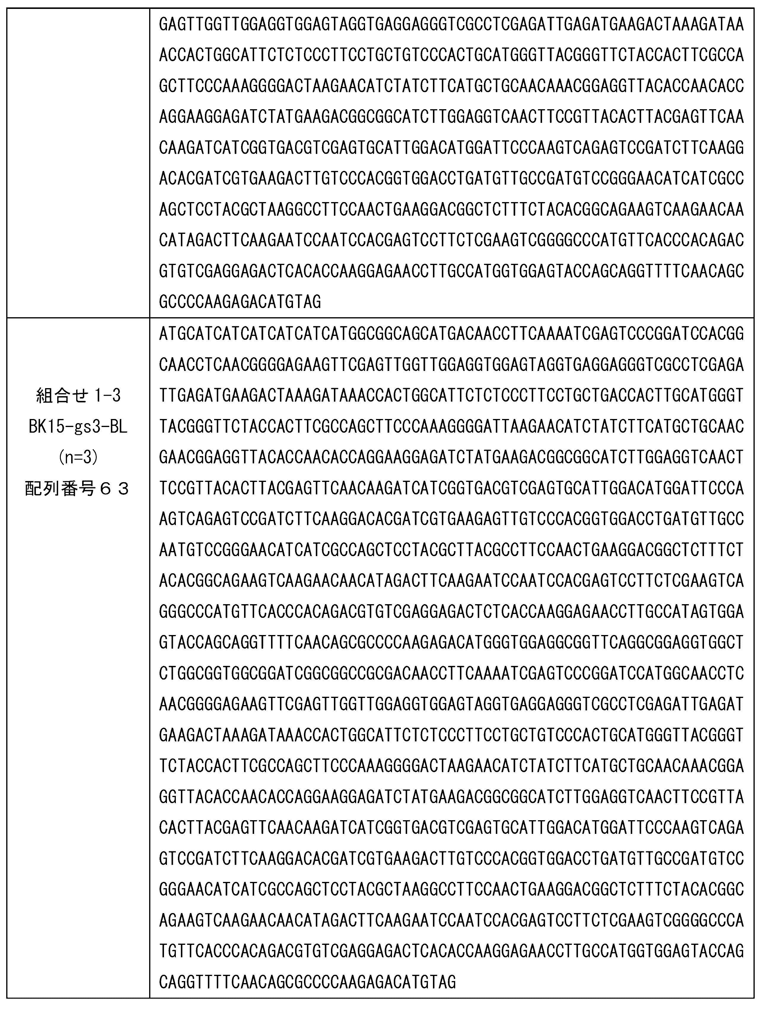
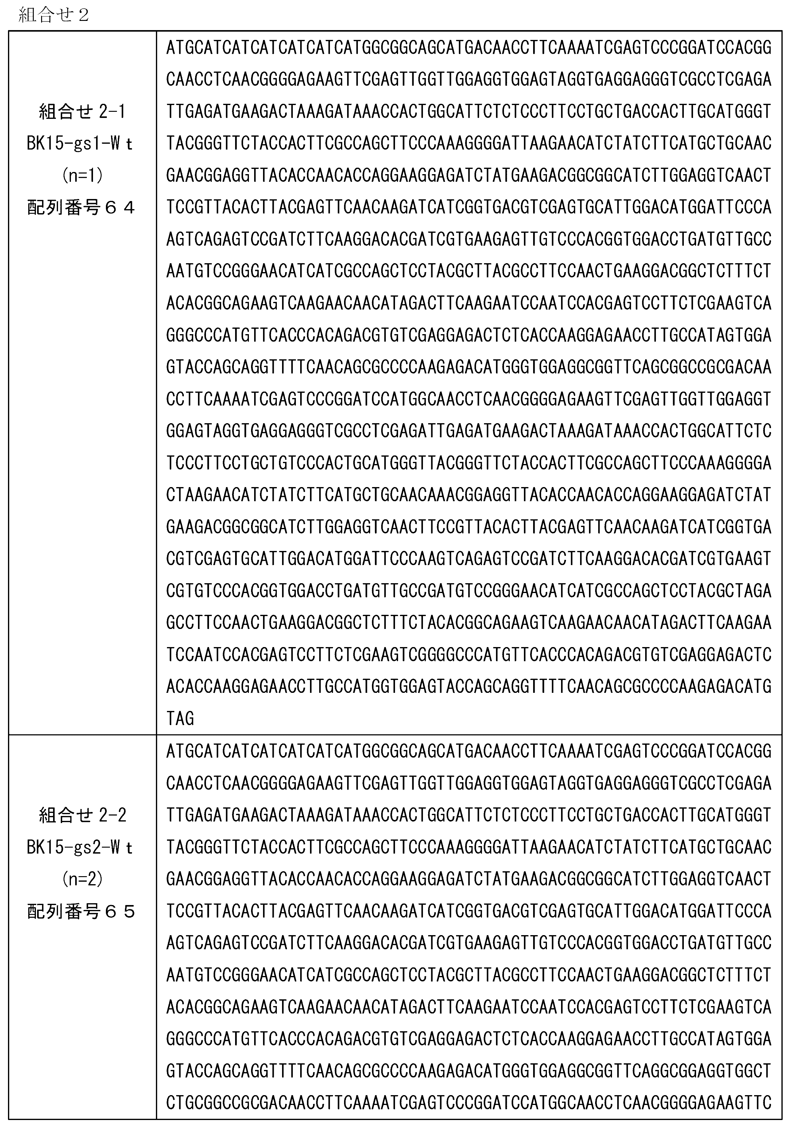
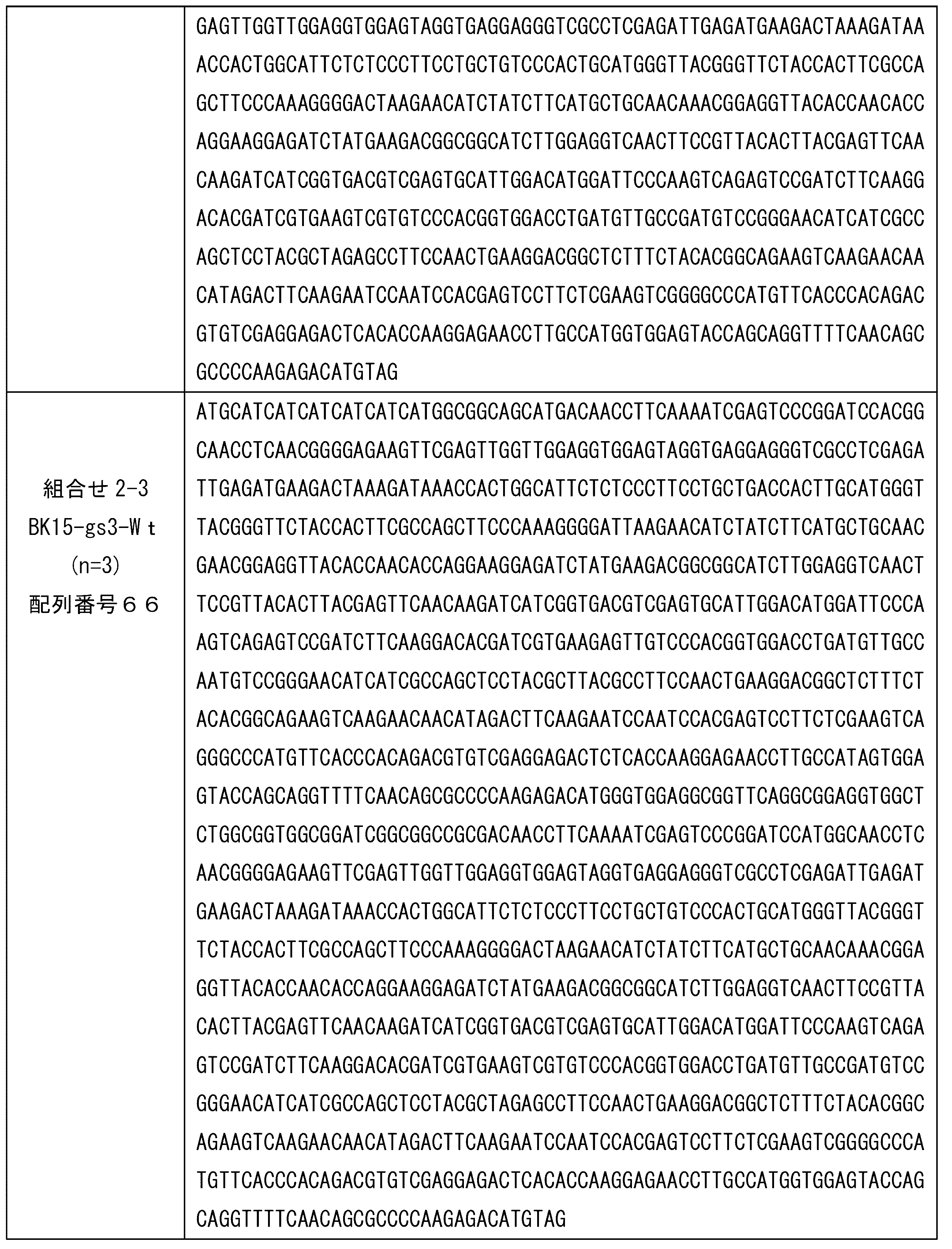
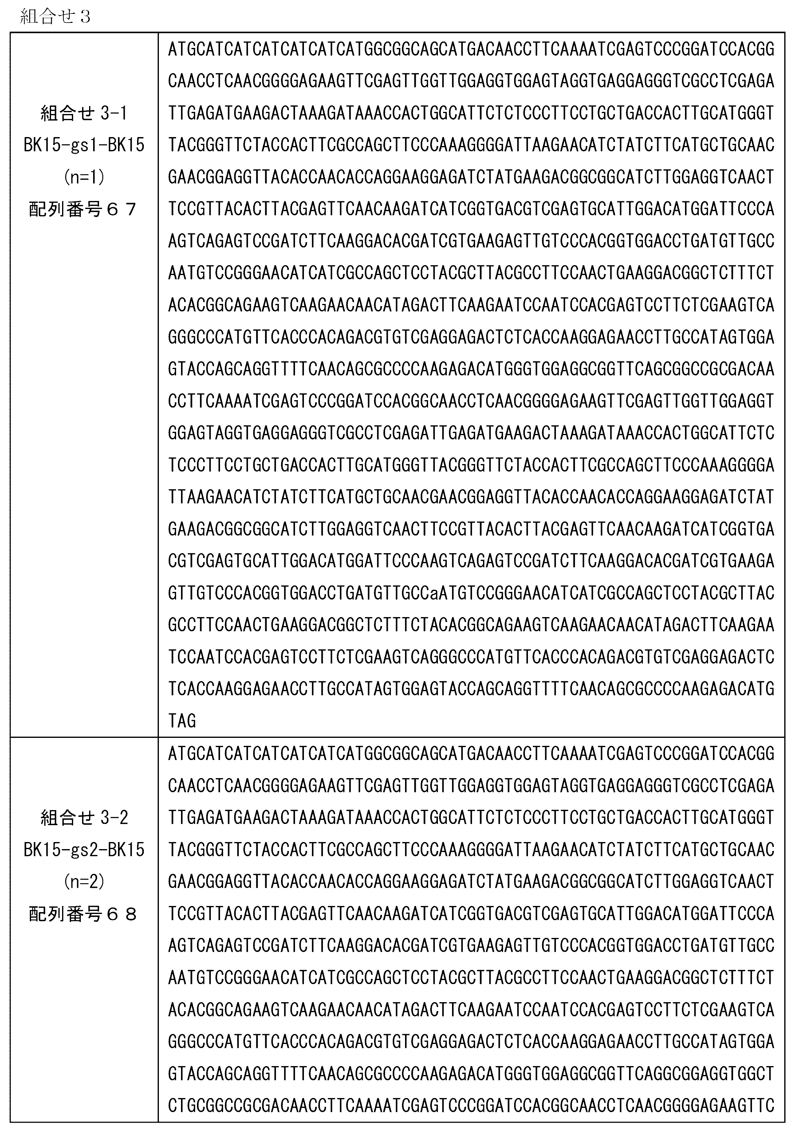

なお、ネガティブコントロールとして、BK15のみを導入した発現ベクター、BLのみを導入した発現ベクターを、同様にして構築した。下記表に、前記BK15単独または前記BL単独の発現ベクターにより発現されるタンパク質のアミノ酸配列およびそれをコードするポリヌクレオチドの塩基配列を示す。なお、下記アミノ酸配列において、下線部は、前記FRET型蛍光タンパク質複合体と同様である。
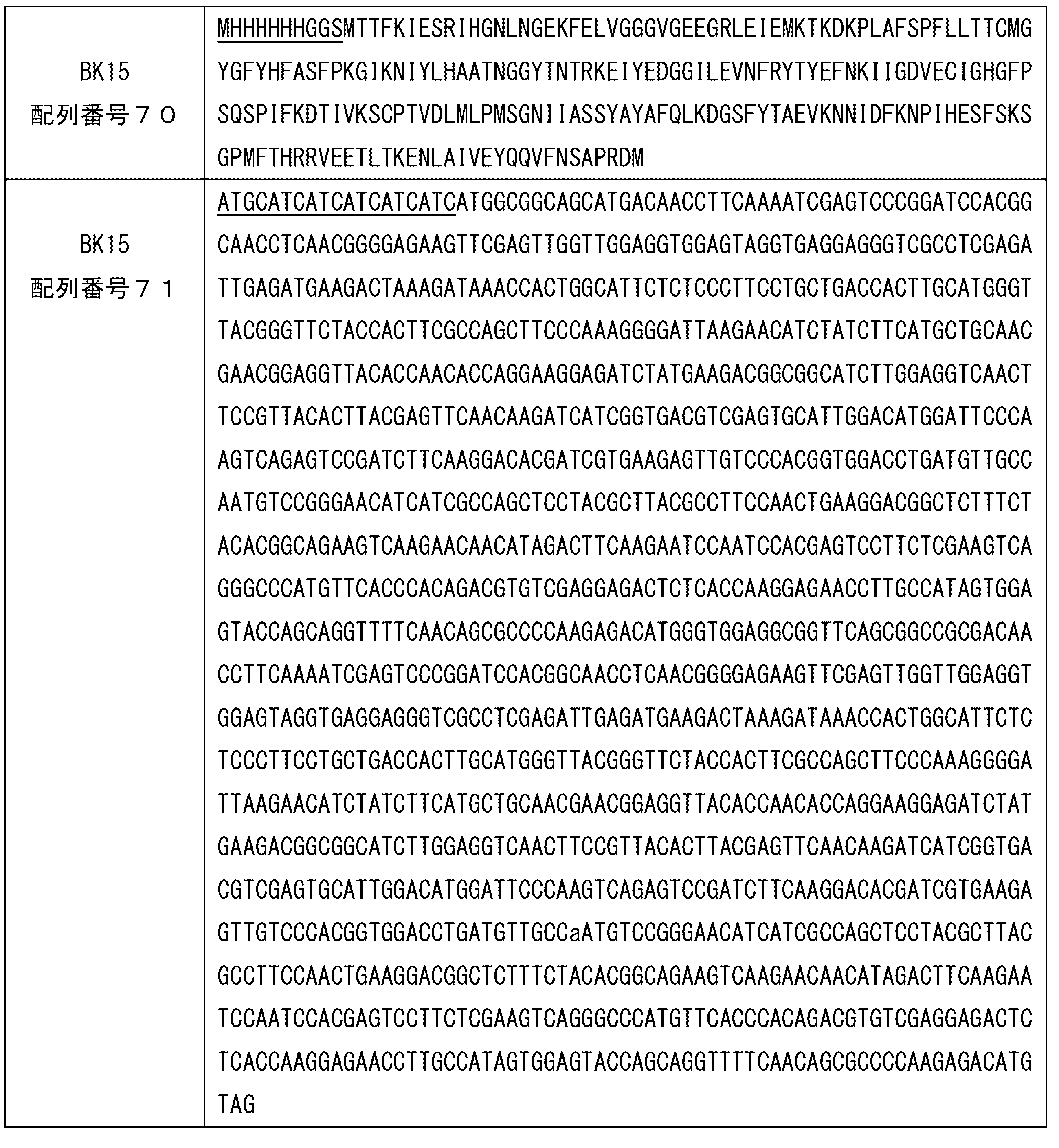

(2)大腸菌への導入
大腸菌DH5α株に、前記各発現ベクターを、それぞれ単独で、ヒートショック法により形質導入した。得られた形質転換体を、抗生物質(アンピシリン)100μg/mLを含有するLB培地を用いて、37℃で16~18時間培養した。そして、培養した菌体を集菌し、得られたペレットを、プロテアーゼ阻害剤(cOmplete,EDTA-free、ロシュ社製)1錠を含むPBS溶液40mLを用いて、2回洗浄した。前記洗浄後のペレットを、前記プロテアーゼ阻害剤を含むPBS溶液1.5mLに懸濁した。つぎに、得られた懸濁液を、超音波ホモジナイザー(QSONICA、ワケンビーテック株式会社製)を用いて、Amp25%、1分間の条件で、2回超音波処理した。そして、前記処理後の懸濁液を、1300rpm、4℃の条件で、10分間遠心し、得られた上清を回収した。各発現ベクターを導入した形質転換体から得られた上清を、前記表7~9に示すFRET型蛍光タンパク質複合体サンプルとした。前記各上清中のタンパク質濃度は、前記各上清に、Protein Assay(Bio Rad社製)を添加後、マイクロプレートリーダー(Infinite(登録商標) M1000Pro、TECAN社製)を用いて、562nmにおける吸光度を測定することにより決定した。
大腸菌DH5α株に、前記各発現ベクターを、それぞれ単独で、ヒートショック法により形質導入した。得られた形質転換体を、抗生物質(アンピシリン)100μg/mLを含有するLB培地を用いて、37℃で16~18時間培養した。そして、培養した菌体を集菌し、得られたペレットを、プロテアーゼ阻害剤(cOmplete,EDTA-free、ロシュ社製)1錠を含むPBS溶液40mLを用いて、2回洗浄した。前記洗浄後のペレットを、前記プロテアーゼ阻害剤を含むPBS溶液1.5mLに懸濁した。つぎに、得られた懸濁液を、超音波ホモジナイザー(QSONICA、ワケンビーテック株式会社製)を用いて、Amp25%、1分間の条件で、2回超音波処理した。そして、前記処理後の懸濁液を、1300rpm、4℃の条件で、10分間遠心し、得られた上清を回収した。各発現ベクターを導入した形質転換体から得られた上清を、前記表7~9に示すFRET型蛍光タンパク質複合体サンプルとした。前記各上清中のタンパク質濃度は、前記各上清に、Protein Assay(Bio Rad社製)を添加後、マイクロプレートリーダー(Infinite(登録商標) M1000Pro、TECAN社製)を用いて、562nmにおける吸光度を測定することにより決定した。
[実施例2]
本発明のFRET型蛍光タンパク質複合体の蛍光活性を確認した。
本発明のFRET型蛍光タンパク質複合体の蛍光活性を確認した。
前記実施例1で調製した、BK15-gs1-BL、BK15-gs1-Wtの上清サンプルを、2μmol/Lとなるように希釈した。これら希釈サンプル50μLについて、前記マイクロプレートリーダーを用い、下記測定条件で蛍光強度(FI)を測定した。また、ネガティブコントロールであるBK15の上清サンプルについても、同様に測定した。プレートは、HTS 384well C-Flat Fluorescence Black Plate (#781076、greiner bio-one)を使用した。
(測定条件)
励起波長:400nm(バンド幅:5nm)
蛍光(検出)波長:516nm(バンド幅:5nm)
レーザー強度(Gain):105
励起波長:400nm(バンド幅:5nm)
蛍光(検出)波長:516nm(バンド幅:5nm)
レーザー強度(Gain):105
励起波長(Ex)400nm、蛍光波長(Em)516nmに固定した結果を、図1に示す。図1は、各FRET型蛍光タンパク質複合体について、上記条件での蛍光強度(FI)を示すグラフである。図1に示すように、BK15単独と比較して、BK15と、BLまたはWtとを連結したFRET型蛍光タンパク質複合体は、より強い蛍光強度の発光を示した。前記FRET型蛍光タンパク質複合体において前記第2蛍光タンパク質に該当するBLおよびWtは、外部からの励起波長400nmよりも、前記複合体内のBK15の蛍光波長512nmにおいて、より強い蛍光強度を示す。このため、BK15とBLまたはWtとを連結したFRET型蛍光タンパク質複合体とすることで、前記複合体内の励起によって、BK15単独よりも強い発光強度を実現できる。また、BLまたはWt単独の場合、それらを発光させるには、例えば、励起波長507~508nmの照射が必要であるが、その場合、得られる発光の波長516~517nmであるため、発光の視認には、他の光をカットする光学フィルムの使用が必要になる。しかしながら、前記FRET型蛍光タンパク質複合体は、BLまたはWtに適した励起波長(507~508nm)の光ではなく、BK15を発光させる励起波長(400nm)の光の照射が可能であり、さらにBK15の発光により、BLまたはWtを励起して発光させることができる。このため、前述のような光学フィルムも不要である。
[実施例3]
本発明のFRET型蛍光タンパク質複合体の蛍光活性を確認した。
本発明のFRET型蛍光タンパク質複合体の蛍光活性を確認した。
前記実施例1で調製した、BK15-gs2-BL、BK15-gs2-WtおよびBK15-gs2-BK15の上清サンプルを、2μmol/Lとなるように希釈した。これら希釈サンプル50μLについて、前記マイクロプレートリーダーを用い、下記測定条件で、前記実施例2と同様にして、蛍光強度(FI)を測定した。また、ネガティブコントロールであるBK15の上清サンプルおよびBLの上清サンプルについても、同様に測定した。
(測定条件)
励起波長:350~650nm(バンド幅:5nm)
蛍光(検出)波長:350~650nm(バンド幅:5nm)
レーザー強度(Gain):105
励起波長:350~650nm(バンド幅:5nm)
蛍光(検出)波長:350~650nm(バンド幅:5nm)
レーザー強度(Gain):105
励起波長(Ex)が400nmであり、蛍光検出波長(Em)が400~600nmの場合の結果を、図2(A)に示し、前記図2(A)における最も高い蛍光強度の結果を、図2(B)に示す。また、表15に、最大の蛍光強度および前記蛍光強度を示した蛍光検出波長を示す。
図2(A)および(B)に示すように、BK単独およびBL単独の場合と比較して、各FRET型蛍光タンパク質複合体によれば、蛍光強度が有意に増加し、具体的には、蛍光極大波長における蛍光強度が有意に増加した。また、図2(A)および表15に示すように、前記第1蛍光タンパク質としてBK15を使用し、前記第2蛍光タンパク質として前記第1蛍光タンパク質とは別の蛍光タンパク質であるBLまたはWtを使用したBK15-gs2-BLおよびBK15-gs2-Wtは、最も高い蛍光強度を示す波長が、BK単独よりも長波長側にシフトした。これらの結果から、前記第1蛍光タンパク質であるBK15が400nmの励起光で励起され、それにより得られる発光により、前記第2蛍光タンパク質(BL、Wt)がさらに励起され、発光したことがわかる。なお、図示していないが、Wt単独の結果は、BLと同様である。
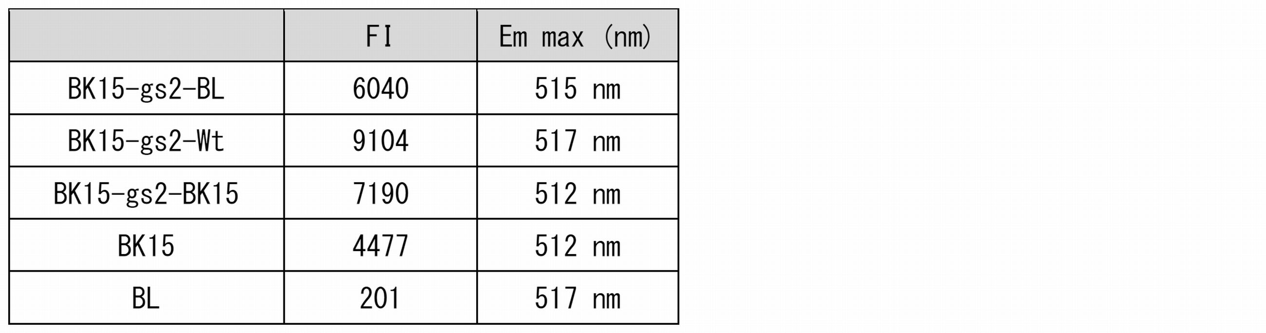
また、励起波長の全範囲および蛍光波長の全範囲の測定結果を、図3に示す。図3の各図は、X軸方向が、励起波長を示し、Y軸方向が、蛍光波長を示し、Z軸方向が、蛍光強度を示す。また、表16に、発光ピークの発光強度、最大励起波長、発光極大波長を示す。
図3に示すように、BK15単独は、400nm等の低波長域では、発光ピークを示すものの、その強度FIは、15,000程度であった。他方、BL単独は、400nmを含む低波長域では発光ピークは示さないが、高波長域の強度FIは、BK15よりも一桁大きい150,000を示した。これに対して、前記FRET型蛍光タンパク質複合体は、いずれも、400nm等の低波長域のピークの他に、高波長域においてもピークが確認できた。この結果からも、前記FRET型蛍光タンパク質複合体は、前記図2で述べたように、400nmで励起した場合、第1蛍光タンパク質のBK15が励起され発光し、この発光によって、さらに第2蛍光タンパク質であるBL、Wtが励起され発光していることがわかる。

[実施例4]
本発明のFRET型蛍光タンパク質複合体の蛍光活性を確認した。
本発明のFRET型蛍光タンパク質複合体の蛍光活性を確認した。
前記実施例1で調製した、BK15-gs3-BL、BK15-gs3-WtおよびBK15-gs3-BK15の上清サンプルを、2μmol/Lとなるように希釈した。これら希釈サンプル50μLについて、前記マイクロプレートリーダーを用い、下記測定条件で、前記実施例2と同様にして、蛍光強度(FI)を測定した。また、ネガティブコントロールであるBK15の上清サンプルおよびBLの上清サンプルについても、同様に測定した。
(測定条件)
励起波長:350~650nm(バンド幅:5nm)
蛍光(検出)波長:350~650nm(バンド幅:5nm)
レーザー強度(Gain):105
励起波長:350~650nm(バンド幅:5nm)
蛍光(検出)波長:350~650nm(バンド幅:5nm)
レーザー強度(Gain):105
励起波長(Ex)が400nmであり、蛍光検出波長(Em)が400~600nmの場合の結果を、図4(A)に示し、前記図4(A)における最も高い蛍光強度の結果を、図4(B)に示す。また、表17に、最大の蛍光強度および前記蛍光強度を示した蛍光検出波長を示す。
図4(A)および(B)に示すように、BK単独およびBL単独の場合と比較して、各FRET型蛍光タンパク質複合体によれば、蛍光強度が有意に増加し、具体的には、蛍光極大波長における蛍光強度が有意に増加した。また、図4(A)および表17に示すように、前記第1蛍光タンパク質としてBK15を使用し、前記第2蛍光タンパク質として前記第1蛍光タンパク質とは別の蛍光タンパク質であるBLまたはWtを使用したBK15-gs3-BLおよびBK15-gs3-Wtは、最も高い蛍光強度を示す波長が、BK単独よりも長波長側にシフトした。これらの結果から、前記第1蛍光タンパク質であるBK15が400nmの励起光で励起され、それにより得られる発光により、前記第2蛍光タンパク質(BL、Wt)がさらに励起され、発光したことがわかる。なお、図示していないが、Wt単独の結果は、BLと同様である。
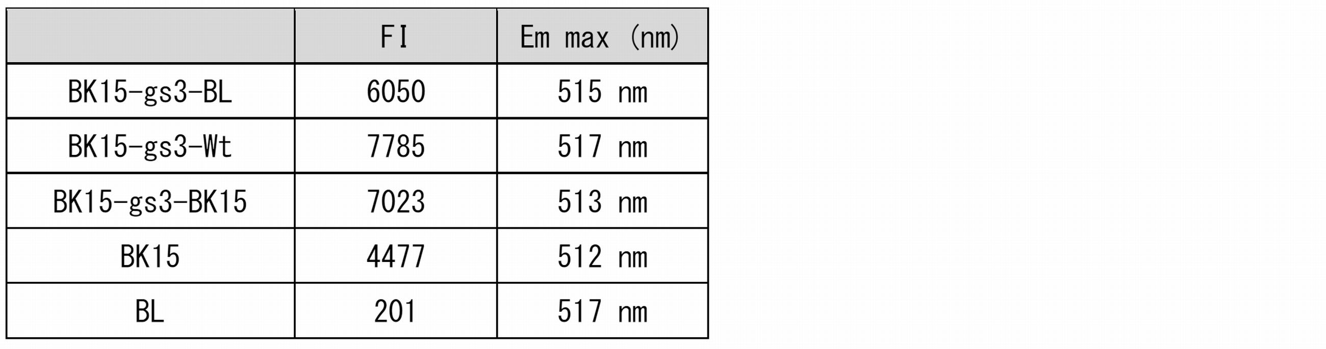
また、励起波長の全範囲および蛍光波長の全範囲の測定結果を、図5に示す。図5の各図は、図4と同様に、X軸方向が、励起波長を示し、Y軸方向が、蛍光波長を示し、Z軸方向が、蛍光強度を示す。また、表18に、最大の蛍光強度および前記蛍光強度を示した蛍光検出波長を示す。前述のように、BK15単独は、400nm等の低波長域では、発光ピークを示すものの、その強度FIは、15,000程度であった。他方、BL単独は、400nmを含む低波長域では発光ピークは示さないが、高波長域の強度FIは、BK15よりも一桁大きい150,000を示した。これに対して、図5に示すように、前記FRET型蛍光タンパク質複合体は、いずれも、400nm等の低波長域のピークの他に、高波長域においてもピークが確認できた。この結果からも、前記FRET型蛍光タンパク質複合体は、前記図4で述べたように、400nmで励起した場合、第1蛍光タンパク質のBK15が励起され発光し、この発光によって、さらに第2蛍光タンパク質であるBL、Wtが励起され発光していることがわかる。

以上、実施形態および実施例を参照して本発明を説明したが、本発明は、上記実施形態および実施例に限定されるものではない。本発明の構成や詳細には、本発明のスコープ内で当業者が理解しうる様々な変更をできる。
この出願は、2016年11月30日に出願された日本出願特願2016-232746を基礎とする優先権を主張し、その開示の全てをここに取り込む。
<付記>
上記の実施形態および実施例の一部または全部は、以下の付記のように記載されうるが、以下には限られない。
(付記1)
第1蛍光タンパク質と第2蛍光タンパク質とを含み、
前記第1蛍光タンパク質と前記第2蛍光タンパク質とが連結されており、
前記第1蛍光タンパク質と前記第2蛍光タンパク質との組み合わせは、前記第1蛍光タンパク質の蛍光波長(L1)と、前記第2蛍光タンパク質の励起波長(E2)とが、重複している組み合わせであることを特徴とする蛍光タンパク質複合体。
(付記2)
前記第2蛍光タンパク質は、
前記第1蛍光タンパク質の励起波長(E1)で前記第2蛍光タンパク質を励起した際の発光強度(I2E1)と、前記第1蛍光タンパク質の蛍光波長(L1)で前記第2蛍光タンパク質を励起した際の発光強度(I2L1)とが、I2E1<I2L1の関係を満たすタンパク質である、付記1記載の蛍光タンパク質複合体。
(付記3)
前記第1蛍光タンパク質と前記第2蛍光タンパク質とが、異なるタンパク質である、付記1または2記載の蛍光タンパク質複合体。
(付記4)
前記第1蛍光タンパク質の最大励起波長と前記第2蛍光タンパク質の最大励起波長とが異なる、付記3記載の蛍光タンパク質複合体。
(付記5)
前記第1蛍光タンパク質の蛍光波長(L1)と、前記第2蛍光タンパク質の励起波長(E2)とが、350~650nmの波長を含む、付記1から4のいずれか一項に記載の蛍光タンパク質複合体。
(付記6)
前記第1蛍光タンパク質の蛍光波長(L1)が、前記第2蛍光タンパク質の最大励起波長(E2max)を含む、付記1から5のいずれか一項に記載の蛍光タンパク質複合体。
(付記7)
前記第2蛍光タンパク質の蛍光波長(L2)が、490~650nmの範囲を含む、付記1から6のいずれか一項に記載の蛍光タンパク質複合体。
(付記8)
前記第1蛍光タンパク質と前記第2蛍光タンパク質とが、リンカーを介して連結されている、付記1から7のいずれか一項に記載の蛍光タンパク質複合体。
(付記9)
前記リンカーが、ペプチドリンカーである、付記8記載の蛍光タンパク質複合体。
(付記10)
前記ペプチドリンカーが、グリシンセリンリンカー領域を含む、付記9記載の蛍光タンパク質複合体。
(付記11)
前記グリシンセリンリンカー領域が、配列番号48(GGGGS)のアミノ酸配列からなるペプチド単位を有する、付記10記載の蛍光タンパク質複合体。
(付記12)
前記グリシンセリンリンカー領域が、前記ペプチド単位が1~3個連結されたリンカーである、付記11記載の蛍光タンパク質複合体。
(付記13)
付記1から12のいずれか一項に記載の蛍光タンパク質複合体に、前記蛍光タンパク質複合体における前記第1蛍光タンパク質の励起波長の光を照射する工程を含み、
前記第1蛍光タンパク質に、前記第1蛍光タンパク質の励起波長の光を照射することで、前記第1蛍光タンパク質を発光させ、
前記第1蛍光タンパク質の発光により、前記蛍光タンパク質複合体における前記第2蛍光タンパク質を励起して、前記第2蛍光タンパク質を発光させることを特徴とする蛍光タンパク質の発光方法。
(付記14)
さらに、前記第2蛍光タンパク質の発光の検出工程を含む、付記13記載の発光方法。
(付記15)
第1蛍光タンパク質をコードする第1核酸配列と、第2蛍光タンパク質をコードする第2核酸配列とを含み、
前記第1核酸配列と前記第2核酸配列とは、前記第1蛍光タンパク質と前記第2蛍光タンパク質とが連結された複合体として発現されるように、連結されており、
前記第1蛍光タンパク質と前記第2蛍光タンパク質の組み合わせは、前記第1蛍光タンパク質の蛍光波長(L1)と、前記第2蛍光タンパク質の励起波長(E2)とが、重複している組み合わせであることを特徴とする、蛍光タンパク質複合体をコードする遺伝子。
(付記16)
前記第1核酸配列と前記第2核酸配列とが、リンカーをコードする核酸配列を介して連結されている、付記15記載の遺伝子。
(付記17)
付記15または16記載の蛍光タンパク質複合体をコードする遺伝子を含むことを特徴とする発現ベクター。
(付記18)
付記15または16記載の蛍光タンパク質複合体をコードする遺伝子または付記17記載の発現ベクターを含むことを特徴とする形質転換体。
上記の実施形態および実施例の一部または全部は、以下の付記のように記載されうるが、以下には限られない。
(付記1)
第1蛍光タンパク質と第2蛍光タンパク質とを含み、
前記第1蛍光タンパク質と前記第2蛍光タンパク質とが連結されており、
前記第1蛍光タンパク質と前記第2蛍光タンパク質との組み合わせは、前記第1蛍光タンパク質の蛍光波長(L1)と、前記第2蛍光タンパク質の励起波長(E2)とが、重複している組み合わせであることを特徴とする蛍光タンパク質複合体。
(付記2)
前記第2蛍光タンパク質は、
前記第1蛍光タンパク質の励起波長(E1)で前記第2蛍光タンパク質を励起した際の発光強度(I2E1)と、前記第1蛍光タンパク質の蛍光波長(L1)で前記第2蛍光タンパク質を励起した際の発光強度(I2L1)とが、I2E1<I2L1の関係を満たすタンパク質である、付記1記載の蛍光タンパク質複合体。
(付記3)
前記第1蛍光タンパク質と前記第2蛍光タンパク質とが、異なるタンパク質である、付記1または2記載の蛍光タンパク質複合体。
(付記4)
前記第1蛍光タンパク質の最大励起波長と前記第2蛍光タンパク質の最大励起波長とが異なる、付記3記載の蛍光タンパク質複合体。
(付記5)
前記第1蛍光タンパク質の蛍光波長(L1)と、前記第2蛍光タンパク質の励起波長(E2)とが、350~650nmの波長を含む、付記1から4のいずれか一項に記載の蛍光タンパク質複合体。
(付記6)
前記第1蛍光タンパク質の蛍光波長(L1)が、前記第2蛍光タンパク質の最大励起波長(E2max)を含む、付記1から5のいずれか一項に記載の蛍光タンパク質複合体。
(付記7)
前記第2蛍光タンパク質の蛍光波長(L2)が、490~650nmの範囲を含む、付記1から6のいずれか一項に記載の蛍光タンパク質複合体。
(付記8)
前記第1蛍光タンパク質と前記第2蛍光タンパク質とが、リンカーを介して連結されている、付記1から7のいずれか一項に記載の蛍光タンパク質複合体。
(付記9)
前記リンカーが、ペプチドリンカーである、付記8記載の蛍光タンパク質複合体。
(付記10)
前記ペプチドリンカーが、グリシンセリンリンカー領域を含む、付記9記載の蛍光タンパク質複合体。
(付記11)
前記グリシンセリンリンカー領域が、配列番号48(GGGGS)のアミノ酸配列からなるペプチド単位を有する、付記10記載の蛍光タンパク質複合体。
(付記12)
前記グリシンセリンリンカー領域が、前記ペプチド単位が1~3個連結されたリンカーである、付記11記載の蛍光タンパク質複合体。
(付記13)
付記1から12のいずれか一項に記載の蛍光タンパク質複合体に、前記蛍光タンパク質複合体における前記第1蛍光タンパク質の励起波長の光を照射する工程を含み、
前記第1蛍光タンパク質に、前記第1蛍光タンパク質の励起波長の光を照射することで、前記第1蛍光タンパク質を発光させ、
前記第1蛍光タンパク質の発光により、前記蛍光タンパク質複合体における前記第2蛍光タンパク質を励起して、前記第2蛍光タンパク質を発光させることを特徴とする蛍光タンパク質の発光方法。
(付記14)
さらに、前記第2蛍光タンパク質の発光の検出工程を含む、付記13記載の発光方法。
(付記15)
第1蛍光タンパク質をコードする第1核酸配列と、第2蛍光タンパク質をコードする第2核酸配列とを含み、
前記第1核酸配列と前記第2核酸配列とは、前記第1蛍光タンパク質と前記第2蛍光タンパク質とが連結された複合体として発現されるように、連結されており、
前記第1蛍光タンパク質と前記第2蛍光タンパク質の組み合わせは、前記第1蛍光タンパク質の蛍光波長(L1)と、前記第2蛍光タンパク質の励起波長(E2)とが、重複している組み合わせであることを特徴とする、蛍光タンパク質複合体をコードする遺伝子。
(付記16)
前記第1核酸配列と前記第2核酸配列とが、リンカーをコードする核酸配列を介して連結されている、付記15記載の遺伝子。
(付記17)
付記15または16記載の蛍光タンパク質複合体をコードする遺伝子を含むことを特徴とする発現ベクター。
(付記18)
付記15または16記載の蛍光タンパク質複合体をコードする遺伝子または付記17記載の発現ベクターを含むことを特徴とする形質転換体。
本発明によれば、前記第1蛍光タンパク質と前記蛍光タンパク質とを前述の条件で組合せることにより、例えば、外部からの励起光が、前記第2蛍光タンパク質の励起条件とは異なる場合や最大励起波長から外れている場合であっても、前記第1蛍光タンパク質の発光による励起により、前記第2蛍光タンパク質を発光することができる。このため、本発明によれば、例えば、蛍光タンパク質を単独で使用する場合と比較して、より広い光学的条件の設定が可能になる。
Claims (18)
- 第1蛍光タンパク質と第2蛍光タンパク質とを含み、
前記第1蛍光タンパク質と前記第2蛍光タンパク質とが連結されており、
前記第1蛍光タンパク質と前記第2蛍光タンパク質との組み合わせは、前記第1蛍光タンパク質の蛍光波長(L1)と、前記第2蛍光タンパク質の励起波長(E2)とが、重複している組み合わせであることを特徴とする蛍光タンパク質複合体。 - 前記第2蛍光タンパク質は、
前記第1蛍光タンパク質の励起波長(E1)で前記第2蛍光タンパク質を励起した際の発光強度(I2E1)と、前記第1蛍光タンパク質の蛍光波長(L1)で前記第2蛍光タンパク質を励起した際の発光強度(I2L1)とが、I2E1<I2L1の関係を満たすタンパク質である、請求項1記載の蛍光タンパク質複合体。 - 前記第1蛍光タンパク質と前記第2蛍光タンパク質とが、異なるタンパク質である、請求項1または2記載の蛍光タンパク質複合体。
- 前記第1蛍光タンパク質の最大励起波長と前記第2蛍光タンパク質の最大励起波長とが異なる、請求項3記載の蛍光タンパク質複合体。
- 前記第1蛍光タンパク質の蛍光波長(L1)と、前記第2蛍光タンパク質の励起波長(E2)とが、350~650nmの波長を含む、請求項1から4のいずれか一項に記載の蛍光タンパク質複合体。
- 前記第1蛍光タンパク質の蛍光波長(L1)が、前記第2蛍光タンパク質の最大励起波長(E2max)を含む、請求項1から5のいずれか一項に記載の蛍光タンパク質複合体。
- 前記第2蛍光タンパク質の蛍光波長(L2)が、490~650nmの範囲を含む、請求項1から6のいずれか一項に記載の蛍光タンパク質複合体。
- 前記第1蛍光タンパク質と前記第2蛍光タンパク質とが、リンカーを介して連結されている、請求項1から7のいずれか一項に記載の蛍光タンパク質複合体。
- 前記リンカーが、ペプチドリンカーである、請求項8記載の蛍光タンパク質複合体。
- 前記ペプチドリンカーが、グリシンセリンリンカー領域を含む、請求項9記載の蛍光タンパク質複合体。
- 前記グリシンセリンリンカー領域が、配列番号48(GGGGS)のアミノ酸配列からなるペプチド単位を有する、請求項10記載の蛍光タンパク質複合体。
- 前記グリシンセリンリンカー領域が、前記ペプチド単位が1~3個連結されたリンカーである、請求項11記載の蛍光タンパク質複合体。
- 請求項1から12のいずれか一項に記載の蛍光タンパク質複合体に、前記蛍光タンパク質複合体における前記第1蛍光タンパク質の励起波長の光を照射する工程を含み、
前記第1蛍光タンパク質に、前記第1蛍光タンパク質の励起波長の光を照射することで、前記第1蛍光タンパク質を発光させ、
前記第1蛍光タンパク質の発光により、前記蛍光タンパク質複合体における前記第2蛍光タンパク質を励起して、前記第2蛍光タンパク質を発光させることを特徴とする蛍光タンパク質の発光方法。 - さらに、前記第2蛍光タンパク質の発光の検出工程を含む、請求項13記載の発光方法。
- 第1蛍光タンパク質をコードする第1核酸配列と、第2蛍光タンパク質をコードする第2核酸配列とを含み、
前記第1核酸配列と前記第2核酸配列とは、前記第1蛍光タンパク質と前記第2蛍光タンパク質とが連結された複合体として発現されるように、連結されており、
前記第1蛍光タンパク質と前記第2蛍光タンパク質の組み合わせは、前記第1蛍光タンパク質の蛍光波長(L1)と、前記第2蛍光タンパク質の励起波長(E2)とが、重複している組み合わせであることを特徴とする、蛍光タンパク質複合体をコードする遺伝子。 - 前記第1核酸配列と前記第2核酸配列とが、リンカーをコードする核酸配列を介して連結されている、請求項15記載の遺伝子。
- 請求項15または16記載の蛍光タンパク質複合体をコードする遺伝子を含むことを特徴とする発現ベクター。
- 請求項15または16記載の蛍光タンパク質複合体をコードする遺伝子または請求項17記載の発現ベクターを含むことを特徴とする形質転換体。
Priority Applications (1)
| Application Number | Priority Date | Filing Date | Title |
|---|---|---|---|
| JP2018553656A JPWO2018100803A1 (ja) | 2016-11-30 | 2017-08-03 | 蛍光タンパク質複合体、および蛍光タンパク質の発光方法 |
Applications Claiming Priority (2)
| Application Number | Priority Date | Filing Date | Title |
|---|---|---|---|
| JP2016-232746 | 2016-11-30 | ||
| JP2016232746 | 2016-11-30 |
Publications (1)
| Publication Number | Publication Date |
|---|---|
| WO2018100803A1 true WO2018100803A1 (ja) | 2018-06-07 |
Family
ID=62241436
Family Applications (1)
| Application Number | Title | Priority Date | Filing Date |
|---|---|---|---|
| PCT/JP2017/028174 Ceased WO2018100803A1 (ja) | 2016-11-30 | 2017-08-03 | 蛍光タンパク質複合体、および蛍光タンパク質の発光方法 |
Country Status (2)
| Country | Link |
|---|---|
| JP (1) | JPWO2018100803A1 (ja) |
| WO (1) | WO2018100803A1 (ja) |
-
2017
- 2017-08-03 WO PCT/JP2017/028174 patent/WO2018100803A1/ja not_active Ceased
- 2017-08-03 JP JP2018553656A patent/JPWO2018100803A1/ja active Pending
Non-Patent Citations (2)
| Title |
|---|
| ARAI RYOICHI ET AL.: "Conformations of Variably Linked Chimeric Proteins Evaluated by Synchrotron X-ray Small-Angle Scattering", PROTEINS, vol. 57, no. 4, 2004, pages 829 - 838, XP002358153 * |
| LI GANG ET AL.: "Construction of a linker library with widely controllable flexibility for fusion protein design", APPL. MICROBIOL. BIOTECHNOL., vol. 100, no. 1, January 2016 (2016-01-01), pages 215 - 225, XP035870356 * |
Also Published As
| Publication number | Publication date |
|---|---|
| JPWO2018100803A1 (ja) | 2019-06-27 |
Similar Documents
| Publication | Publication Date | Title |
|---|---|---|
| US20140059722A1 (en) | Biosensors | |
| EP2050332B1 (en) | Application of fluorescent protein to horticultural plant | |
| Xiao et al. | An Agrobacterium-mediated transient expression method contributes to functional analysis of a transcription factor and potential application of gene editing in Chenopodium quinoa | |
| JP5527654B2 (ja) | 植物の油脂を増産させる遺伝子及びその利用方法 | |
| ES2453377T3 (es) | Gen de la flavonoide 3', 5' hidroxilasa de la Flor de Santa Lucía | |
| Lee et al. | SP-LL-37, human antimicrobial peptide, enhances disease resistance in transgenic rice | |
| JP5856638B2 (ja) | 植物の油脂を増産させる遺伝子及びその利用方法 | |
| JP6525290B2 (ja) | 新規タンパク質、新規遺伝子、発現ベクター、形質転換体、形質転換体の製造方法、および新規蛍光タンパク質のスクリーニング方法 | |
| Do et al. | Efficient regeneration of transgenic rice from embryogenic callus via Agrobacterium-mediated transformation: a case study using GFP and apple MdFT1 genes | |
| CN106480069B (zh) | 黄瓜CsERF025基因及其在促进黄瓜果实顺直发育中的应用 | |
| CN110172471A (zh) | 大豆转化过程中非种系事件的早期检测和去除 | |
| WO2018100803A1 (ja) | 蛍光タンパク質複合体、および蛍光タンパク質の発光方法 | |
| Levy et al. | Transient Agrobacterium-mediated gene expression in the Arabidopsis hydroponics root system for subcellular localization studies | |
| JP2025002120A (ja) | シイノトモシビタケ由来の発光関連遺伝子 | |
| CN116926114A (zh) | 一种热激蛋白基因LbHSP90在改变切花百合抗低温胁迫中的应用 | |
| JP7031929B2 (ja) | 新規タンパク質および新規遺伝子 | |
| JP6933409B2 (ja) | 新規タンパク質、新規遺伝子、形質転換体、形質転換体の製造方法、および新規蛍光タンパク質のスクリーニング方法 | |
| US10023619B1 (en) | Production of spider silk protein in corn | |
| Skopelitis et al. | Overcoming extensive redundancy in the arabidopsis TREHALOSE-6-PHOSPHATE PHOSPHATASE gene family reveals connections to development and iron homeostasis | |
| Khosla et al. | Ratiometric measurement of protein abundance after transient expression of a transgene in Nicotiana benthamiana | |
| EP2298883B1 (en) | Novel selection marker gene and use thereof | |
| CN105732785B (zh) | 蛋白质GhDHN1在调控植物抗逆性中的应用 | |
| JP2025003314A (ja) | シイノトモシビタケ由来の発光関連遺伝子 | |
| CN121737205B (zh) | PoPILS1a基因在调控植物种子发育中的应用 | |
| CN119431533A (zh) | 调控紫丁香花青苷合成的转录因子及其应用 |
Legal Events
| Date | Code | Title | Description |
|---|---|---|---|
| 121 | Ep: the epo has been informed by wipo that ep was designated in this application |
Ref document number: 17875668 Country of ref document: EP Kind code of ref document: A1 |
|
| ENP | Entry into the national phase |
Ref document number: 2018553656 Country of ref document: JP Kind code of ref document: A |
|
| NENP | Non-entry into the national phase |
Ref country code: DE |
|
| 122 | Ep: pct application non-entry in european phase |
Ref document number: 17875668 Country of ref document: EP Kind code of ref document: A1 |