WO2018100736A1 - 電力変換装置の制御装置 - Google Patents
電力変換装置の制御装置 Download PDFInfo
- Publication number
- WO2018100736A1 WO2018100736A1 PCT/JP2016/085936 JP2016085936W WO2018100736A1 WO 2018100736 A1 WO2018100736 A1 WO 2018100736A1 JP 2016085936 W JP2016085936 W JP 2016085936W WO 2018100736 A1 WO2018100736 A1 WO 2018100736A1
- Authority
- WO
- WIPO (PCT)
- Prior art keywords
- value
- error signal
- current
- current sensor
- detection value
- Prior art date
- Legal status (The legal status is an assumption and is not a legal conclusion. Google has not performed a legal analysis and makes no representation as to the accuracy of the status listed.)
- Ceased
Links
Images



Classifications
-
- H—ELECTRICITY
- H02—GENERATION; CONVERSION OR DISTRIBUTION OF ELECTRIC POWER
- H02M—APPARATUS FOR CONVERSION BETWEEN AC AND AC, BETWEEN AC AND DC, OR BETWEEN DC AND DC, AND FOR USE WITH MAINS OR SIMILAR POWER SUPPLY SYSTEMS; CONVERSION OF DC OR AC INPUT POWER INTO SURGE OUTPUT POWER; CONTROL OR REGULATION THEREOF
- H02M1/00—Details of apparatus for conversion
- H02M1/32—Means for protecting converters other than automatic disconnection
-
- H—ELECTRICITY
- H02—GENERATION; CONVERSION OR DISTRIBUTION OF ELECTRIC POWER
- H02M—APPARATUS FOR CONVERSION BETWEEN AC AND AC, BETWEEN AC AND DC, OR BETWEEN DC AND DC, AND FOR USE WITH MAINS OR SIMILAR POWER SUPPLY SYSTEMS; CONVERSION OF DC OR AC INPUT POWER INTO SURGE OUTPUT POWER; CONTROL OR REGULATION THEREOF
- H02M7/00—Conversion of AC power input into DC power output; Conversion of DC power input into AC power output
- H02M7/42—Conversion of DC power input into AC power output without possibility of reversal
- H02M7/44—Conversion of DC power input into AC power output without possibility of reversal by static converters
- H02M7/48—Conversion of DC power input into AC power output without possibility of reversal by static converters using discharge tubes with control electrode or semiconductor devices with control electrode
-
- H—ELECTRICITY
- H02—GENERATION; CONVERSION OR DISTRIBUTION OF ELECTRIC POWER
- H02M—APPARATUS FOR CONVERSION BETWEEN AC AND AC, BETWEEN AC AND DC, OR BETWEEN DC AND DC, AND FOR USE WITH MAINS OR SIMILAR POWER SUPPLY SYSTEMS; CONVERSION OF DC OR AC INPUT POWER INTO SURGE OUTPUT POWER; CONTROL OR REGULATION THEREOF
- H02M7/00—Conversion of AC power input into DC power output; Conversion of DC power input into AC power output
- H02M7/42—Conversion of DC power input into AC power output without possibility of reversal
- H02M7/44—Conversion of DC power input into AC power output without possibility of reversal by static converters
- H02M7/48—Conversion of DC power input into AC power output without possibility of reversal by static converters using discharge tubes with control electrode or semiconductor devices with control electrode
- H02M7/53—Conversion of DC power input into AC power output without possibility of reversal by static converters using discharge tubes with control electrode or semiconductor devices with control electrode using devices of a triode or transistor type requiring continuous application of a control signal
- H02M7/537—Conversion of DC power input into AC power output without possibility of reversal by static converters using discharge tubes with control electrode or semiconductor devices with control electrode using devices of a triode or transistor type requiring continuous application of a control signal using semiconductor devices only, e.g. single switched pulse inverters
- H02M7/5387—Conversion of DC power input into AC power output without possibility of reversal by static converters using discharge tubes with control electrode or semiconductor devices with control electrode using devices of a triode or transistor type requiring continuous application of a control signal using semiconductor devices only, e.g. single switched pulse inverters in a bridge configuration
- H02M7/53871—Conversion of DC power input into AC power output without possibility of reversal by static converters using discharge tubes with control electrode or semiconductor devices with control electrode using devices of a triode or transistor type requiring continuous application of a control signal using semiconductor devices only, e.g. single switched pulse inverters in a bridge configuration with automatic control of output voltage or current
-
- H—ELECTRICITY
- H02—GENERATION; CONVERSION OR DISTRIBUTION OF ELECTRIC POWER
- H02M—APPARATUS FOR CONVERSION BETWEEN AC AND AC, BETWEEN AC AND DC, OR BETWEEN DC AND DC, AND FOR USE WITH MAINS OR SIMILAR POWER SUPPLY SYSTEMS; CONVERSION OF DC OR AC INPUT POWER INTO SURGE OUTPUT POWER; CONTROL OR REGULATION THEREOF
- H02M7/00—Conversion of AC power input into DC power output; Conversion of DC power input into AC power output
- H02M7/42—Conversion of DC power input into AC power output without possibility of reversal
- H02M7/44—Conversion of DC power input into AC power output without possibility of reversal by static converters
- H02M7/48—Conversion of DC power input into AC power output without possibility of reversal by static converters using discharge tubes with control electrode or semiconductor devices with control electrode
- H02M7/53—Conversion of DC power input into AC power output without possibility of reversal by static converters using discharge tubes with control electrode or semiconductor devices with control electrode using devices of a triode or transistor type requiring continuous application of a control signal
- H02M7/537—Conversion of DC power input into AC power output without possibility of reversal by static converters using discharge tubes with control electrode or semiconductor devices with control electrode using devices of a triode or transistor type requiring continuous application of a control signal using semiconductor devices only, e.g. single switched pulse inverters
- H02M7/5387—Conversion of DC power input into AC power output without possibility of reversal by static converters using discharge tubes with control electrode or semiconductor devices with control electrode using devices of a triode or transistor type requiring continuous application of a control signal using semiconductor devices only, e.g. single switched pulse inverters in a bridge configuration
- H02M7/53871—Conversion of DC power input into AC power output without possibility of reversal by static converters using discharge tubes with control electrode or semiconductor devices with control electrode using devices of a triode or transistor type requiring continuous application of a control signal using semiconductor devices only, e.g. single switched pulse inverters in a bridge configuration with automatic control of output voltage or current
- H02M7/53875—Conversion of DC power input into AC power output without possibility of reversal by static converters using discharge tubes with control electrode or semiconductor devices with control electrode using devices of a triode or transistor type requiring continuous application of a control signal using semiconductor devices only, e.g. single switched pulse inverters in a bridge configuration with automatic control of output voltage or current with analogue control of three-phase output
-
- H—ELECTRICITY
- H02—GENERATION; CONVERSION OR DISTRIBUTION OF ELECTRIC POWER
- H02H—EMERGENCY PROTECTIVE CIRCUIT ARRANGEMENTS
- H02H7/00—Emergency protective circuit arrangements specially adapted for specific types of electric machines or apparatus or for sectionalised protection of cable or line systems, and effecting automatic switching in the event of an undesired change from normal working conditions
- H02H7/10—Emergency protective circuit arrangements specially adapted for specific types of electric machines or apparatus or for sectionalised protection of cable or line systems, and effecting automatic switching in the event of an undesired change from normal working conditions for converters; for rectifiers
- H02H7/12—Emergency protective circuit arrangements specially adapted for specific types of electric machines or apparatus or for sectionalised protection of cable or line systems, and effecting automatic switching in the event of an undesired change from normal working conditions for converters; for rectifiers for static converters or rectifiers
- H02H7/122—Emergency protective circuit arrangements specially adapted for specific types of electric machines or apparatus or for sectionalised protection of cable or line systems, and effecting automatic switching in the event of an undesired change from normal working conditions for converters; for rectifiers for static converters or rectifiers for inverters, i.e. DC/AC converters
- H02H7/1227—Emergency protective circuit arrangements specially adapted for specific types of electric machines or apparatus or for sectionalised protection of cable or line systems, and effecting automatic switching in the event of an undesired change from normal working conditions for converters; for rectifiers for static converters or rectifiers for inverters, i.e. DC/AC converters responsive to abnormalities in the output circuit, e.g. short circuit
-
- H—ELECTRICITY
- H02—GENERATION; CONVERSION OR DISTRIBUTION OF ELECTRIC POWER
- H02J—ELECTRIC POWER NETWORKS; CIRCUIT ARRANGEMENTS OR SYSTEMS FOR SUPPLYING OR DISTRIBUTING ELECTRIC POWER; SYSTEMS FOR STORING ELECTRIC ENERGY
- H02J3/00—Circuit arrangements for AC mains or AC distribution networks
- H02J3/38—Arrangements for feeding a single network from two or more generators or sources in parallel; Arrangements for feeding already energised networks from additional generators or sources in parallel
-
- H—ELECTRICITY
- H02—GENERATION; CONVERSION OR DISTRIBUTION OF ELECTRIC POWER
- H02M—APPARATUS FOR CONVERSION BETWEEN AC AND AC, BETWEEN AC AND DC, OR BETWEEN DC AND DC, AND FOR USE WITH MAINS OR SIMILAR POWER SUPPLY SYSTEMS; CONVERSION OF DC OR AC INPUT POWER INTO SURGE OUTPUT POWER; CONTROL OR REGULATION THEREOF
- H02M1/00—Details of apparatus for conversion
- H02M1/0003—Details of control, feedback or regulation circuits
- H02M1/0009—Devices or circuits for detecting current in a converter
-
- Y—GENERAL TAGGING OF NEW TECHNOLOGICAL DEVELOPMENTS; GENERAL TAGGING OF CROSS-SECTIONAL TECHNOLOGIES SPANNING OVER SEVERAL SECTIONS OF THE IPC; TECHNICAL SUBJECTS COVERED BY FORMER USPC CROSS-REFERENCE ART COLLECTIONS [XRACs] AND DIGESTS
- Y02—TECHNOLOGIES OR APPLICATIONS FOR MITIGATION OR ADAPTATION AGAINST CLIMATE CHANGE
- Y02E—REDUCTION OF GREENHOUSE GAS [GHG] EMISSIONS, RELATED TO ENERGY GENERATION, TRANSMISSION OR DISTRIBUTION
- Y02E10/00—Energy generation through renewable energy sources
- Y02E10/50—Photovoltaic [PV] energy
- Y02E10/56—Power conversion systems, e.g. maximum power point trackers
Definitions
- This invention relates to the control apparatus of a power converter device.
- Patent Document 1 discloses a control device for a power conversion device.
- the control device includes a current detection unit and an abnormality detection unit.
- the current detection unit outputs an error signal through the wiring when a current abnormality such as an overcurrent of the power conversion device is detected.
- the abnormality detection unit detects a current abnormality based on the error signal.
- the abnormality detection unit performs filtering on the error signal in order to suppress malfunction due to noise. For this reason, detection of the current abnormality of the power converter is delayed.
- the objective of this invention is providing the control apparatus of the power converter device which can detect the electric current abnormality of a power converter device without delay.
- the control device of the power conversion device outputs an error signal when the detection value of the current sensor that detects the current flowing through the power conversion device is larger than a preset overcurrent determination value, and outputs the error signal to the error signal.
- a current detection unit that outputs a state detection value that is larger than the value corresponding to the error signal, and an input of the state detection value of the current detection unit via wiring, and the state detection value of the current detection unit
- an abnormality detection unit that outputs an error signal when it is larger than the set overcurrent abnormality determination value and detects an abnormality based on the error signal.
- a control device for a power converter detects a detection value of a first current sensor that detects a first current flowing in a first part of the power converter and a second current that flows in a second part of the power converter.
- An error signal is output when the deviation from the detected value of the second current sensor is greater than a preset deviation determination value, and a state detection value greater than the value corresponding to the error signal is set based on the error signal.
- an abnormality detection unit that detects an abnormality based on the error signal.
- the current detection unit outputs a state detection value larger than the value corresponding to the error signal to the abnormality detection unit.
- the abnormality detection unit detects an abnormality without performing filter processing. For this reason, it is possible to detect the current abnormality of the power converter without delay.
- FIG. 2 It is a block diagram of the power supply system with which the control apparatus of the power converter device in Embodiment 2 of this invention is applied. It is a figure for demonstrating the electric current detection part and abnormality detection part of the control apparatus of the power converter device in Embodiment 2 of this invention.
- FIG. 1 is a configuration diagram of a power supply system to which a control device for a power conversion device according to Embodiment 1 of the present invention is applied.
- the power supply system includes a power system 1, a solar cell module 2, a power conversion device 3, a current sensor 4, and a control device 5.
- Power system 1 is installed outdoors.
- the solar cell module 2 is provided outdoors.
- the power converter 3 is provided outdoors.
- the power conversion device 3 is electrically connected between the power system 1 and the solar cell module 2.
- the current sensor 4 is provided between the power system 1 and the power conversion device 3.
- the input unit of the control device 5 is connected to the output unit of the current sensor 4.
- the output unit of the control device 5 is connected to the input unit of the power conversion device 3.
- the electric power system 1 is operated by an electric power company.
- the solar cell module 2 converts solar light energy into DC power.
- the power conversion device 3 receives supply of DC power from the solar cell module 2.
- the power conversion device 3 converts the DC power into AC power.
- the power conversion device 3 converts the DC power into three-phase AC power.
- the power conversion device 3 supplies the AC power to the power system 1.
- the current sensor 4 detects the current flowing through the power conversion device 3. For example, the current sensor 4 detects an output current of at least one phase of the power conversion device 3.
- the control device 5 controls the operation of the power conversion device 3 based on the detection value of the current sensor 4.
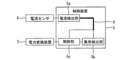
- FIG. 2 is a block diagram of the control device for the power conversion device according to Embodiment 1 of the present invention.
- the control device 5 includes a current detection unit 5a, an abnormality detection unit 5b, and a control unit 5c.
- the current detection unit 5a outputs an error signal when the detection value of the current sensor 4 is larger than a preset overcurrent determination value.
- the current detection unit 5a outputs a state detection value larger than the value corresponding to the error signal based on the error signal.
- the abnormality detection unit 5b receives an input of the state detection value of the current detection unit 5a via the wiring 6.
- the abnormality detection unit 5b outputs an error signal when the state detection value of the current detection unit 5a is larger than a preset overcurrent abnormality determination value.
- the abnormality detection unit 5b detects an abnormality based on the error signal.
- the control unit 5c receives an input of a detection value of the current sensor 4 through the current detection unit 5a and the wiring 6.
- the control unit 5c receives an error signal input from the abnormality detection unit 5b.
- the control unit 5c controls the operation of the power conversion device 3 based on the detection value of the current sensor 4 from the current detection unit 5a and the error signal from the abnormality detection unit 5b.
- FIG. 3 is a diagram for illustrating a current detection unit and an abnormality detection unit of the control device for the power conversion device according to Embodiment 1 of the present invention.
- the current detection unit 5 a is provided on the current detection substrate 7.
- the current detection unit 5 a includes an overcurrent comparator 8, a switch 9, and an adder 10.
- the overcurrent comparator 8 compares the detection value of the current sensor 4 with the overcurrent determination value. When the detection value of the current sensor 4 is larger than the overcurrent determination value, the overcurrent comparator 8 outputs an error signal. For example, the overcurrent comparator 8 outputs a high level signal. When the detection value of the current sensor 4 is equal to or less than the overcurrent determination value, the overcurrent comparator 8 does not output an error signal. For example, the overcurrent comparator 8 outputs a low level signal.
- the switch 9 operates based on the error signal from the overcurrent comparator 8. For example, the switch 9 is closed by an error signal from the overcurrent comparator 8.
- the adder 10 adds the detection value of the current sensor 4 and the value from the switch 9.
- the adder 10 outputs a state detection value obtained by adding the detection value of the current sensor 4 and the value from the switch 9. At this time, the state detection value is set to a value larger than the value corresponding to the error signal of the overcurrent comparator 8.
- the abnormality detection unit 5b is provided on the control board 11.
- the abnormality detection unit 5b includes an abnormality detection comparator 12.
- the abnormality detection comparator 12 receives the input of the state detection value from the adder 10.
- the abnormality detection comparator 12 compares the state detection value with the overcurrent abnormality determination value. When the state detection value is larger than the overcurrent abnormality determination value, the abnormality detection comparator 12 outputs an error signal. For example, the abnormality detection comparator 12 outputs a high level signal. When the state detection value is equal to or less than the overcurrent abnormality determination value, the abnormality detection comparator 12 does not output an error signal. For example, the abnormality detection comparator 12 outputs a low level signal.
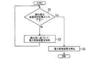
- FIG. 4 is a flowchart for explaining the operation of the control device for the power conversion device according to Embodiment 1 of the present invention.
- step S1 the control device 5 determines whether or not the detection value of the current sensor 4 is larger than the overcurrent determination value.
- step S1 If the detection value of the current sensor 4 is equal to or less than the overcurrent determination value in step S1, the control device 5 performs the operation of step S2.
- step S ⁇ b> 2 the control device 5 controls the operation of the power conversion device 3 based on the detection value of the current sensor 4. Thereafter, the control device 5 performs the operation of Step S1.
- step S1 When the detection value of the current sensor 4 is larger than the overcurrent determination value in step S1, the control device 5 performs the operation of step S3. In step S3, the control device 5 stops the power conversion device 3. Thereafter, the control device 5 ends the operation.
- the current detection unit 5a outputs a state detection value larger than the value corresponding to the error signal toward the abnormality detection unit 5b.
- the abnormality detection unit 5b detects an overcurrent abnormality without performing filter processing with a large time delay. For this reason, the current abnormality of the power converter 3 can be detected without delay.
- the current detection unit 5a can be realized by the overcurrent comparator 8, the switch 9, and the adder 10.
- the abnormality detection unit 5b can be realized by the abnormality detection comparator 12. For this reason, it is possible to detect an overcurrent abnormality of the power conversion device 3 without delay with a simple configuration.
- the abnormality detection unit 5b receives an input of the state detection value via the wiring 6.
- the control unit 5 c receives an input of a detection value of the current sensor 4 through the wiring 6. For this reason, the number of wirings 6 between the current detection board 7 and the control board 11 can be reduced.
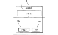
- FIG. 5 is a hardware configuration diagram of the control device for the power conversion device according to Embodiment 1 of the present invention.
- Each function of the control device 5 can be realized by a processing circuit.
- the processing circuit includes at least one processor 13a and at least one memory 13b.
- the processing circuit comprises at least one dedicated hardware 14.
- each function of the control device 5 is realized by software, firmware, or a combination of software and firmware. At least one of software and firmware is described as a program. At least one of software and firmware is stored in at least one memory 13b. At least one processor 13a implements each function of the control device 5 by reading and executing a program stored in at least one memory 13b.
- the at least one processor 13a is also referred to as a CPU (Central Processing Unit), a central processing unit, a processing unit, an arithmetic unit, a microprocessor, a microcomputer, and a DSP.
- the at least one memory 13b is a nonvolatile or volatile semiconductor memory such as RAM, ROM, flash memory, EPROM, or EEPROM, a magnetic disk, a flexible disk, an optical disk, a compact disk, a mini disk, a DVD, or the like.
- the processing circuit comprises at least one dedicated hardware 14, the processing circuit is implemented, for example, as a single circuit, a composite circuit, a programmed processor, a parallel programmed processor, an ASIC, an FPGA, or a combination thereof.
- each function of the control device 5 is realized by a processing circuit.
- each function of the control device 5 is collectively realized by a processing circuit.
- control device 5 may be realized by dedicated hardware 14, and the other part may be realized by software or firmware.
- the function of the current detection unit 5a is realized by a processing circuit as dedicated hardware 14, and for functions other than the current detection unit 5a, at least one processor 13a reads a program stored in at least one memory 13b. It may be realized by executing.
- the processing circuit realizes each function of the control device 5 by the hardware 14, software, firmware, or a combination thereof.
- FIG. FIG. 6 is a configuration diagram of a power supply system to which the control device for the power conversion device according to Embodiment 2 of the present invention is applied.
- symbol is attached
- the first current sensor 15 is provided between the power system 1 and the power converter 3.
- the first current sensor 15 corresponds to a first part of the power conversion device 3.
- the first current sensor 15 is provided in the first phase of the power conversion device 3.
- the second current sensor 16 is provided between the power system 1 and the power conversion device 3.
- the second current sensor 16 corresponds to the second part of the power conversion device 3.
- the second current sensor 16 is provided in the second phase of the power conversion device 3.
- the first current sensor 15 detects the first current flowing through the first part of the power conversion device 3. For example, the first current sensor 15 detects the first-phase output current of the power conversion device 3.
- the second current sensor 16 detects a second current flowing through the second part of the power conversion device 3. For example, the second current sensor 16 detects the output current of the second phase of the power conversion device 3.
- the control device 5 controls the operation of the power conversion device 3 based on the average value of the detection value of the first current sensor 15 and the detection value of the second current sensor 16.
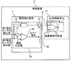
- FIG. 7 is a diagram for illustrating a current detection unit and an abnormality detection unit of the control device for a power conversion device according to Embodiment 2 of the present invention.
- the current detection unit 5 a is provided on the current detection substrate 7.
- the current detection unit 5 a includes a subtracter 17, an average value calculator 18, a deviation comparator 19, a switch 20, and an adder 21.
- the subtractor 17 calculates a deviation between the detection value of the first current sensor 15 and the detection value of the second current sensor 16.
- the average value calculator 18 calculates the average value of the detection value of the first current sensor 15 and the detection value of the second current sensor 16.
- the deviation comparator 19 compares the deviation between the detection value of the first current sensor 15 and the detection value of the second current sensor 16 and the deviation determination value. When the deviation between the detection value of the first current sensor 15 and the detection value of the second current sensor 16 is larger than the deviation determination value, the deviation comparator 19 outputs an error signal. For example, the deviation comparator 19 outputs a high level signal. When the deviation between the detection value of the first current sensor 15 and the detection value of the second current sensor 16 is equal to or less than the deviation determination value, the deviation comparator 19 does not output an error signal. For example, the deviation comparator 19 outputs a low level signal.
- the switch 20 operates based on an error signal from the deviation comparator 19. For example, the switch 20 is closed by an error signal from the deviation comparator 19.
- the adder 21 adds the value from the average value calculator 18 and the value from the switch 20.
- the adder 21 outputs a state detection value obtained by adding the value from the average value calculator 18 and the value from the switch 20. At this time, the state detection value is set to a value larger than the value corresponding to the error signal of the deviation comparator 19.
- the abnormality detection unit 5b is provided on the control board 11.
- the abnormality detection unit 5b includes an abnormality detection comparator 12.
- the abnormality detection comparator 12 receives an input of the state detection value from the adder 21.
- the abnormality detection comparator 12 compares the state detection value with the deviation abnormality determination value. When the state detection value is larger than the deviation abnormality determination value, the abnormality detection comparator 12 outputs an error signal. For example, the abnormality detection comparator 12 outputs a high level signal. When the state detection value is equal to or less than the deviation abnormality determination value, the abnormality detection comparator 12 does not output an error signal. For example, the abnormality detection comparator 12 outputs a low level signal.
- the current detection unit 5a outputs a state detection value larger than the value corresponding to the error signal toward the abnormality detection unit 5b.
- the abnormality detection unit 5b detects a current deviation abnormality without performing filter processing with a large time delay. For this reason, the current abnormality of the power converter 3 can be detected without delay.
- the current detection unit 5a can be realized by the subtracter 17, the average value calculator 18, the deviation comparator 19, the switch 20, and the adder 21.
- the abnormality detection unit 5b can be realized by the abnormality detection comparator 12. For this reason, the current deviation abnormality of the power converter 3 can be detected without delay with a simple configuration.
- the abnormality detection unit 5b receives an input of the state detection value via the wiring 6.
- the control unit 5 c receives an input of an average value of the detection value of the first current sensor 15 and the detection value of the second current sensor 16 via the wiring 6. For this reason, the number of wirings 6 between the current detection board 7 and the control board 11 can be reduced.
- control device 5 of the power conversion device 3 can be used in a system that detects current abnormality of the power conversion device 3 without delay.
Landscapes
- Engineering & Computer Science (AREA)
- Power Engineering (AREA)
- Inverter Devices (AREA)
- Power Conversion In General (AREA)
Abstract
電力変換装置の電流異常を遅れることなく検出することができる電力変換装置の制御装置を提供する。電力変換装置の制御装置は、電力変換装置に流れる電流を検出する電流センサの検出値が予め設定された過電流判定値よりも大きい場合にエラー信号を出力し、当該エラー信号に基づいて当該エラー信号に対応した値よりも大きな状態検出値を出力する電流検出部と、配線を介して前記電流検出部の状態検出値の入力を受け付け、前記電流検出部の状態検出値が予め設定された過電流異常判定値よりも大きい場合にエラー信号を出力し、当該エラー信号に基づいて異常を検出する異常検出部と、を備えた。
Description
この発明は、電力変換装置の制御装置に関する。
特許文献1は、電力変換装置の制御装置を開示する。例えば、当該制御装置は、電流検出部と異常検出部とを備える。例えば、電流検出部は、電力変換装置の過電流等の電流異常を検出した場合に配線を介してエラー信号を出力する。例えば、異常検出部は、当該エラー信号に基づいて電流異常を検出する。
この際、異常検出部は、ノイズによる誤動作を抑制するために当該エラー信号に対してフィルタ処理を施す。このため、電力変換装置の電流異常の検出が遅れる。
この発明は、上述の課題を解決するためになされた。この発明の目的は、電力変換装置の電流異常を遅れることなく検出することができる電力変換装置の制御装置を提供することである。
この発明に係る電力変換装置の制御装置は、電力変換装置に流れる電流を検出する電流センサの検出値が予め設定された過電流判定値よりも大きい場合にエラー信号を出力し、当該エラー信号に基づいて当該エラー信号に対応した値よりも大きな状態検出値を出力する電流検出部と、配線を介して前記電流検出部の状態検出値の入力を受け付け、前記電流検出部の状態検出値が予め設定された過電流異常判定値よりも大きい場合にエラー信号を出力し、当該エラー信号に基づいて異常を検出する異常検出部と、を備えた。
この発明に係る電力変換装置の制御装置は、電力変換装置の第1部に流れる第1電流を検出する第1電流センサの検出値と前記電力変換装置の第2部に流れる第2電流を検出する第2電流センサの検出値との偏差が予め設定された偏差判定値よりも大きい場合にエラー信号を出力し、当該エラー信号に基づいて当該エラー信号に対応した値よりも大きな状態検出値を出力する電流検出部と、配線を介して前記電流検出部の状態検出値の入力を受け付け、前記電流検出部の状態検出値が予め設定された偏差異常判定値よりも大きい場合にエラー信号を出力し、当該エラー信号に基づいて異常を検出する異常検出部と、を備えた。
これらの発明によれば、電流検出部は、エラー信号に対応した値よりも大きな状態検出値を異常検出部に向けて出力する。異常検出部は、フィルタ処理を施さずに異常を検出する。このため、電力変換装置の電流異常を遅れることなく検出することができる。
この発明を実施するための形態について添付の図面に従って説明する。なお、各図中、同一または相当する部分には同一の符号が付される。当該部分の重複説明は適宜に簡略化ないし省略する。
実施の形態1.
図1はこの発明の実施の形態1における電力変換装置の制御装置が適用される電源システムの構成図である。
図1はこの発明の実施の形態1における電力変換装置の制御装置が適用される電源システムの構成図である。
図1において、電源システムは、電力系統1と太陽電池モジュール2と電力変換装置3と電流センサ4と制御装置5とを備える。
電力系統1は、屋外に設けられる。太陽電池モジュール2は、屋外に設けられる。電力変換装置3は、屋外に設けられる。電力変換装置3は、電力系統1と太陽電池モジュール2との間に電気的に接続される。
電流センサ4は、電力系統1と電力変換装置3との間に設けられる。制御装置5の入力部は、電流センサ4の出力部に接続される。制御装置5の出力部は、電力変換装置3の入力部に接続される。
例えば、電力系統1は、電力会社により運用される。太陽電池モジュール2は、太陽の光エネルギーを直流電力に変換する。電力変換装置3は、太陽電池モジュール2から直流電力の供給を受ける。電力変換装置3は、当該直流電力を交流電力に変換する。例えば、電力変換装置3は、当該直流電力を三相交流電力に変換する。電力変換装置3は、当該交流電力を電力系統1に供給する。
電流センサ4は、電力変換装置3に流れる電流を検出する。例えば、電流センサ4は、電力変換装置3の少なくとも一相の出力電流を検出する。制御装置5は、電流センサ4の検出値に基づいて電力変換装置3の動作を制御する。
次に、図2を用いて、制御装置5の概要を説明する。
図2はこの発明の実施の形態1における電力変換装置の制御装置のブロック図である。
図2はこの発明の実施の形態1における電力変換装置の制御装置のブロック図である。
図2に示されるように、制御装置5は、電流検出部5aと異常検出部5bと制御部5cとを備える。
電流検出部5aは、電流センサ4の検出値が予め設定された過電流判定値よりも大きい場合にエラー信号を出力する。電流検出部5aは、当該エラー信号に基づいて当該エラー信号に対応した値よりも大きな状態検出値を出力する。
異常検出部5bは、配線6を介して電流検出部5aの状態検出値の入力を受け付ける。異常検出部5bは、電流検出部5aの状態検出値が予め設定された過電流異常判定値よりも大きい場合にエラー信号を出力する。異常検出部5bは、当該エラー信号に基づいて異常を検出する。
制御部5cは、電流検出部5aと配線6とを介して電流センサ4の検出値の入力を受け付ける。制御部5cは、異常検出部5bからのエラー信号の入力を受け付ける。制御部5cは、電流検出部5aからの電流センサ4の検出値と異常検出部5bからのエラー信号に基づいて電力変換装置3の動作を制御する。
次に、図3を用いて、電流検出部5aと異常検出部5bとを説明する。
図3はこの発明の実施の形態1における電力変換装置の制御装置の電流検出部と異常検出部とを説明するための図である。
図3はこの発明の実施の形態1における電力変換装置の制御装置の電流検出部と異常検出部とを説明するための図である。
図3に示されるように、電流検出部5aは、電流検出基板7に設けられる。電流検出部5aは、過電流比較器8とスイッチ9と加算器10とを有する。
過電流比較器8は、電流センサ4の検出値と過電流判定値とを比較する。電流センサ4の検出値が過電流判定値よりも大きい場合、過電流比較器8は、エラー信号を出力する。例えば、過電流比較器8は、ハイレベルの信号を出力する。電流センサ4の検出値が過電流判定値以下の場合、過電流比較器8は、エラー信号を出力しない。例えば、過電流比較器8は、ローレベルの信号を出力する。
スイッチ9は、過電流比較器8からのエラー信号に基づいて動作する。例えば、スイッチ9は、過電流比較器8からのエラー信号により閉じる。
加算器10は、電流センサ4の検出値とスイッチ9からの値とを加算する。加算器10は、電流センサ4の検出値とスイッチ9からの値とを加算した状態検出値を出力する。この際、状態検出値は、過電流比較器8のエラー信号に対応した値よりも大きい値に設定される。
異常検出部5bは、制御基板11に設けられる。異常検出部5bは、異常検出比較器12を有する。
異常検出比較器12は、加算器10から状態検出値の入力を受け付ける。異常検出比較器12は、状態検出値と過電流異常判定値とを比較する。状態検出値が過電流異常判定値よりも大きい場合、異常検出比較器12は、エラー信号を出力する。例えば、異常検出比較器12は、ハイレベルの信号を出力する。状態検出値が過電流異常判定値以下の場合、異常検出比較器12は、エラー信号を出力しない。例えば、異常検出比較器12は、ローレベルの信号を出力する。
次に、図4を用いて、制御装置5の動作の概要を説明する。
図4はこの発明の実施の形態1における電力変換装置の制御装置の動作を説明するためのフローチャートである。
図4はこの発明の実施の形態1における電力変換装置の制御装置の動作を説明するためのフローチャートである。
ステップS1では、制御装置5は、電流センサ4の検出値が過電流判定値よりも大きいか否かを判定する。
ステップS1で電流センサ4の検出値が過電流判定値以下の場合、制御装置5は、ステップS2の動作を行う。ステップS2では、制御装置5は、電流センサ4の検出値に基づいて電力変換装置3の動作を制御する。その後、制御装置5は、ステップS1の動作を行う。
ステップS1で電流センサ4の検出値が過電流判定値よりも大きい場合、制御装置5は、ステップS3の動作を行う。ステップS3では、制御装置5は、電力変換装置3を停止させる。その後、制御装置5は、動作を終了する。
以上で説明した実施の形態1によれば、電流検出部5aは、エラー信号に対応した値よりも大きな状態検出値を異常検出部5bに向けて出力する。異常検出部5bは、時間遅れの大きいフィルタ処理を施さずに過電流異常を検出する。このため、電力変換装置3の電流異常を遅れることなく検出することができる。
その結果、電力変換装置3の故障範囲が広がることを抑制できる。このため、電力変換装置3の故障時における修理の範囲が広がることを抑制できる。また、電力変換装置3の故障時における修理の時間が長くなることを抑制できる。さらに、電力変換装置3の電流異常が遅れることを考慮して、電力変換装置3の通常運転範囲を狭くする必要もなくなる。
また、電流検出部5aは、過電流比較器8とスイッチ9と加算器10とで実現し得る。異常検出部5bは、異常検出比較器12で実現し得る。このため、簡単な構成で、電力変換装置3の過電流異常を遅れることなく検出することができる。
また、異常検出部5bは、配線6を介して状態検出値の入力を受け付ける。制御部5cは、配線6を介して電流センサ4の検出値の入力を受け付ける。このため、電流検出基板7と制御基板11との間の配線6の数を減らすことができる。
次に、図5を用いて、制御装置5の例を説明する。
図5はこの発明の実施の形態1における電力変換装置の制御装置のハードウェア構成図である。
図5はこの発明の実施の形態1における電力変換装置の制御装置のハードウェア構成図である。
制御装置5の各機能は、処理回路により実現し得る。例えば、処理回路は、少なくとも1つのプロセッサ13aと少なくとも1つのメモリ13bとを備える。例えば、処理回路は、少なくとも1つの専用のハードウェア14を備える。
処理回路が少なくとも1つのプロセッサ13aと少なくとも1つのメモリ13bとを備える場合、制御装置5の各機能は、ソフトウェア、ファームウェア、またはソフトウェアとファームウェアとの組み合わせで実現される。ソフトウェアおよびファームウェアの少なくとも一方は、プログラムとして記述される。ソフトウェアおよびファームウェアの少なくとも一方は、少なくとも1つのメモリ13bに格納される。少なくとも1つのプロセッサ13aは、少なくとも1つのメモリ13bに記憶されたプログラムを読み出して実行することにより、制御装置5の各機能を実現する。少なくとも1つのプロセッサ13aは、CPU(Central Processing Unit)、中央処理装置、処理装置、演算装置、マイクロプロセッサ、マイクロコンピュータ、DSPともいう。例えば、少なくとも1つのメモリ13bは、RAM、ROM、フラッシュメモリ、EPROM、EEPROM等の、不揮発性または揮発性の半導体メモリ、磁気ディスク、フレキシブルディスク、光ディスク、コンパクトディスク、ミニディスク、DVD等である。
処理回路が少なくとも1つの専用のハードウェア14を備える場合、処理回路は、例えば、単一回路、複合回路、プログラム化したプロセッサ、並列プログラム化したプロセッサ、ASIC、FPGA、またはこれらの組み合わせで実現される。例えば、制御装置5の各機能は、それぞれ処理回路で実現される。例えば、制御装置5の各機能は、まとめて処理回路で実現される。
制御装置5の各機能について、一部を専用のハードウェア14で実現し、他部をソフトウェアまたはファームウェアで実現してもよい。例えば、電流検出部5aの機能については専用のハードウェア14としての処理回路で実現し、電流検出部5a以外の機能については少なくとも1つのプロセッサ13aが少なくとも1つのメモリ13bに格納されたプログラムを読み出して実行することにより実現してもよい。
このように、処理回路は、ハードウェア14、ソフトウェア、ファームウェア、またはこれらの組み合わせで制御装置5の各機能を実現する。
実施の形態2.
図6はこの発明の実施の形態2における電力変換装置の制御装置が適用される電源システムの構成図である。なお、実施の形態1と同一または相当部分には、同一符号が付される。当該部分の説明は省略される。
図6はこの発明の実施の形態2における電力変換装置の制御装置が適用される電源システムの構成図である。なお、実施の形態1と同一または相当部分には、同一符号が付される。当該部分の説明は省略される。
図6に示されるように、第1電流センサ15は、電力系統1と電力変換装置3との間に設けられる。第1電流センサ15は、電力変換装置3の第1部に対応する。例えば、第1電流センサ15は、電力変換装置3の第1相に設けられる。第2電流センサ16は、電力系統1と電力変換装置3との間に設けられる。第2電流センサ16は、電力変換装置3の第2部に対応する。例えば、第2電流センサ16は、電力変換装置3の第2相に設けられる。
第1電流センサ15は、電力変換装置3の第1部に流れる第1電流を検出する。例えば、第1電流センサ15は、電力変換装置3の第1相の出力電流を検出する。第2電流センサ16は、電力変換装置3の第2部に流れる第2電流を検出する。例えば、第2電流センサ16は、電力変換装置3の第2相の出力電流を検出する。制御装置5は、第1電流センサ15の検出値と第2電流センサ16の検出値との平均値に基づいて電力変換装置3の動作を制御する。
次に、図7を用いて、電流検出部5aと異常検出部5bとを説明する。
図7はこの発明の実施の形態2における電力変換装置の制御装置の電流検出部と異常検出部とを説明するための図である。
図7はこの発明の実施の形態2における電力変換装置の制御装置の電流検出部と異常検出部とを説明するための図である。
図7に示されるように、電流検出部5aは、電流検出基板7に設けられる。電流検出部5aは、減算器17と平均値算出器18と偏差比較器19とスイッチ20と加算器21とを有する。
減算器17は、第1電流センサ15の検出値と第2電流センサ16の検出値との偏差を算出する。
平均値算出器18は、第1電流センサ15の検出値と第2電流センサ16の検出値との平均値を算出する。
偏差比較器19は、第1電流センサ15の検出値と第2電流センサ16の検出値との偏差と偏差判定値とを比較する。第1電流センサ15の検出値と第2電流センサ16の検出値との偏差が偏差判定値よりも大きい場合、偏差比較器19は、エラー信号を出力する。例えば、偏差比較器19は、ハイレベルの信号を出力する。第1電流センサ15の検出値と第2電流センサ16の検出値との偏差が偏差判定値以下の場合、偏差比較器19は、エラー信号を出力しない。例えば、偏差比較器19は、ローレベルの信号を出力する。
スイッチ20は、偏差比較器19からのエラー信号に基づいて動作する。例えば、スイッチ20は、偏差比較器19からのエラー信号により閉じる。
加算器21は、平均値算出器18からの値とスイッチ20からの値とを加算する。加算器21は、平均値算出器18からの値とスイッチ20からの値とを加算した状態検出値を出力する。この際、状態検出値は、偏差比較器19のエラー信号に対応した値よりも大きい値に設定される。
異常検出部5bは、制御基板11に設けられる。異常検出部5bは、異常検出比較器12を有する。
異常検出比較器12は、加算器21から状態検出値の入力を受け付ける。異常検出比較器12は、状態検出値と偏差異常判定値とを比較する。状態検出値が偏差異常判定値よりも大きい場合、異常検出比較器12は、エラー信号を出力する。例えば、異常検出比較器12は、ハイレベルの信号を出力する。状態検出値が偏差異常判定値以下の場合、異常検出比較器12は、エラー信号を出力しない。例えば、異常検出比較器12は、ローレベルの信号を出力する。
以上で説明した実施の形態2によれば、電流検出部5aは、エラー信号に対応した値よりも大きな状態検出値を異常検出部5bに向けて出力する。異常検出部5bは、時間遅れの大きいフィルタ処理を施さずに電流偏差異常を検出する。このため、電力変換装置3の電流異常を遅れることなく検出することができる。
また、電流検出部5aは、減算器17と平均値算出器18と偏差比較器19とスイッチ20と加算器21とで実現し得る。異常検出部5bは、異常検出比較器12で実現し得る。このため、簡単な構成で、電力変換装置3の電流偏差異常を遅れることなく検出することができる。
また、異常検出部5bは、配線6を介して状態検出値の入力を受け付ける。制御部5cは、配線6を介して第1電流センサ15の検出値と第2電流センサ16の検出値との平均値の入力を受け付ける。このため、電流検出基板7と制御基板11との間の配線6の数を減らすことができる。
以上のように、この発明に係る電力変換装置3の制御装置5は、電力変換装置3の電流異常を遅れることなく検出するシステムに利用できる。
1 電力系統、 2 太陽電池モジュール、 3 電力変換装置、 4 電流センサ、 5 制御装置、 5a 電流検出部、 5b 異常検出部、 5c 制御部、 6 配線、 7 電流検出基板、 8 過電流比較器、 9 スイッチ、 10 加算器、 11 制御基板、 12 異常検出比較器、 13a プロセッサ、 13b メモリ、 14 ハードウェア、 15 第1電流センサ、 16 第2電流センサ、 17 減算器、 18 平均値算出器、 19 偏差比較器、 20 スイッチ、 21 加算器
Claims (6)
- 電力変換装置に流れる電流を検出する電流センサの検出値が予め設定された過電流判定値よりも大きい場合にエラー信号を出力し、当該エラー信号に基づいて当該エラー信号に対応した値よりも大きな状態検出値を出力する電流検出部と、
配線を介して前記電流検出部の状態検出値の入力を受け付け、前記電流検出部の状態検出値が予め設定された過電流異常判定値よりも大きい場合にエラー信号を出力し、当該エラー信号に基づいて異常を検出する異常検出部と、
を備えた電力変換装置の制御装置。 - 前記電流検出部は、過電流比較器とスイッチとを有し、前記電流センサの検出値が前記過電流判定値よりも大きい場合に前記過電流比較器がエラー信号を出力し、当該エラー信号による前記スイッチの動作に基づいて当該エラー信号に対応した値よりも大きな状態検出値を出力し、
前記異常検出部は、異常検出比較器を有し、前記電流検出部の状態検出値が前記過電流異常判定値よりも大きい場合に前記異常検出比較器がエラー信号を出力し、当該エラー信号に基づいて異常を検出する請求項1に記載の電力変換装置の制御装置。 - 前記配線を介して前記電流センサの検出値の入力を受け付け、前記電流センサの検出値に基づいて前記電力変換装置を制御する制御部、
を備え、
前記電流検出部は、前記電流センサの検出値が前記過電流判定値よりも大きい場合に前記過電流比較器がエラー信号を出力し、当該エラー信号による前記スイッチの動作に基づいて前記電流センサの検出値に予め設定された値を加算することにより当該エラー信号に対応した値よりも大きな状態検出値を前記配線に出力する請求項2に記載の電力変換装置の制御装置。 - 電力変換装置の第1部に流れる第1電流を検出する第1電流センサの検出値と前記電力変換装置の第2部に流れる第2電流を検出する第2電流センサの検出値との偏差が予め設定された偏差判定値よりも大きい場合にエラー信号を出力し、当該エラー信号に基づいて当該エラー信号に対応した値よりも大きな状態検出値を出力する電流検出部と、
配線を介して前記電流検出部の状態検出値の入力を受け付け、前記電流検出部の状態検出値が予め設定された偏差異常判定値よりも大きい場合にエラー信号を出力し、当該エラー信号に基づいて異常を検出する異常検出部と、
を備えた電力変換装置の制御装置。 - 前記電流検出部は、偏差比較器とスイッチとを有し、前記第1電流センサの検出値と前記第2電流センサの検出値との偏差が前記偏差判定値よりも大きい場合に前記偏差比較器がエラー信号を出力し、当該エラー信号による前記スイッチの動作に基づいて当該エラー信号に対応した値よりも大きな状態検出値を出力し、
前記異常検出部は、異常検出比較器を有し、前記電流検出部の状態検出値が前記偏差異常判定値よりも大きい場合に前記異常検出比較器がエラー信号を出力し、当該エラー信号に基づいて異常を検出する請求項4に記載の電力変換装置の制御装置。 - 前記配線を介して前記第1電流センサの検出値と前記第2電流センサの検出値との平均値の入力を受け付け、前記第1電流センサの検出値と前記第2電流センサの検出値との平均値に基づいて前記電力変換装置を制御する制御部、
を備え、
前記電流検出部は、前記第1電流センサの検出値と前記第2電流センサの検出値との偏差が前記偏差判定値よりも大きい場合に前記偏差比較器がエラー信号を出力し、当該エラー信号による前記スイッチの動作に基づいて前記第1電流センサの検出値と前記第2電流センサの検出値との平均値に予め設定された値を加算することにより当該エラー信号に対応した値よりも大きな状態検出値を前記配線に出力する請求項5に記載の電力変換装置の制御装置。
Priority Applications (3)
| Application Number | Priority Date | Filing Date | Title |
|---|---|---|---|
| JP2018553622A JP6677316B2 (ja) | 2016-12-02 | 2016-12-02 | 電力変換装置の制御装置 |
| US16/330,835 US10581311B2 (en) | 2016-12-02 | 2016-12-02 | Power conversion device including overcurrent detection with reduced delay |
| PCT/JP2016/085936 WO2018100736A1 (ja) | 2016-12-02 | 2016-12-02 | 電力変換装置の制御装置 |
Applications Claiming Priority (1)
| Application Number | Priority Date | Filing Date | Title |
|---|---|---|---|
| PCT/JP2016/085936 WO2018100736A1 (ja) | 2016-12-02 | 2016-12-02 | 電力変換装置の制御装置 |
Publications (1)
| Publication Number | Publication Date |
|---|---|
| WO2018100736A1 true WO2018100736A1 (ja) | 2018-06-07 |
Family
ID=62242065
Family Applications (1)
| Application Number | Title | Priority Date | Filing Date |
|---|---|---|---|
| PCT/JP2016/085936 Ceased WO2018100736A1 (ja) | 2016-12-02 | 2016-12-02 | 電力変換装置の制御装置 |
Country Status (3)
| Country | Link |
|---|---|
| US (1) | US10581311B2 (ja) |
| JP (1) | JP6677316B2 (ja) |
| WO (1) | WO2018100736A1 (ja) |
Citations (3)
| Publication number | Priority date | Publication date | Assignee | Title |
|---|---|---|---|---|
| JPH11215837A (ja) * | 1998-01-30 | 1999-08-06 | Mitsubishi Electric Corp | インバータの過電流保護回路 |
| JP2005094938A (ja) * | 2003-09-18 | 2005-04-07 | Matsushita Electric Ind Co Ltd | インバータ装置 |
| JP2015070702A (ja) * | 2013-09-30 | 2015-04-13 | 株式会社日立産機システム | 電力変換装置および制御方法 |
Family Cites Families (4)
| Publication number | Priority date | Publication date | Assignee | Title |
|---|---|---|---|---|
| JP2605635B2 (ja) | 1994-09-13 | 1997-04-30 | 日本電気株式会社 | 移動通信システムおよびその制御方法 |
| DE19617054C2 (de) * | 1996-04-29 | 2002-05-08 | Semikron Elektronik Gmbh | Überstrom- und Kurzschlußsicherung |
| US20040051383A1 (en) * | 2002-09-12 | 2004-03-18 | Clark Charles Albert | Switching mode current limiting power controller circuit |
| US9225262B2 (en) * | 2012-06-29 | 2015-12-29 | Eaton Corporation | Multi-level inverter apparatus and methods using variable overcurrent response |
-
2016
- 2016-12-02 JP JP2018553622A patent/JP6677316B2/ja active Active
- 2016-12-02 WO PCT/JP2016/085936 patent/WO2018100736A1/ja not_active Ceased
- 2016-12-02 US US16/330,835 patent/US10581311B2/en active Active
Patent Citations (3)
| Publication number | Priority date | Publication date | Assignee | Title |
|---|---|---|---|---|
| JPH11215837A (ja) * | 1998-01-30 | 1999-08-06 | Mitsubishi Electric Corp | インバータの過電流保護回路 |
| JP2005094938A (ja) * | 2003-09-18 | 2005-04-07 | Matsushita Electric Ind Co Ltd | インバータ装置 |
| JP2015070702A (ja) * | 2013-09-30 | 2015-04-13 | 株式会社日立産機システム | 電力変換装置および制御方法 |
Also Published As
| Publication number | Publication date |
|---|---|
| US20190214897A1 (en) | 2019-07-11 |
| US10581311B2 (en) | 2020-03-03 |
| JP6677316B2 (ja) | 2020-04-08 |
| JPWO2018100736A1 (ja) | 2019-10-17 |
Similar Documents
| Publication | Publication Date | Title |
|---|---|---|
| JP5274236B2 (ja) | 3相インバータの電源回路保護装置 | |
| US8319466B2 (en) | Modular line-to-ground fault identification | |
| US11841724B2 (en) | MLPE photovoltaic system and method for photovoltaic string control in MLPE photovoltaic system | |
| US9906134B1 (en) | Insulation detecting circuit, power converting device and insulation impedance value detecting method | |
| JP5110960B2 (ja) | 系統連系インバータ装置 | |
| JP2020058209A (ja) | モータ駆動装置 | |
| JP2009112143A (ja) | 3相交流モータ制御装置および3相交流モータ制御方法 | |
| JP6093555B2 (ja) | 制御システム及び二重化制御方法 | |
| JP6677316B2 (ja) | 電力変換装置の制御装置 | |
| JP7156555B2 (ja) | 電力変換器の制御装置 | |
| CN113228493B (zh) | 复合电力变换系统 | |
| US12081155B2 (en) | Motor control device and abnormality detection method for current detector provided in motor control device | |
| WO2018235278A1 (ja) | 電力変換装置の制御装置 | |
| JP6733818B1 (ja) | 電力変換装置 | |
| JP5578983B2 (ja) | 欠相検出方法 | |
| JPWO2021117146A5 (ja) | ||
| JP6462206B2 (ja) | 電力変換装置および制御方法 | |
| JP4423949B2 (ja) | 交流交流直接変換装置の制御装置 | |
| JP6202896B2 (ja) | 電力変換装置 | |
| CN111480288A (zh) | 电力转换系统 | |
| JP7287570B2 (ja) | 電力変換装置の制御装置 | |
| EP2963754A1 (en) | Decentralized power supply system | |
| JP4974227B2 (ja) | 電力変換装置 | |
| JP6272128B2 (ja) | 系統連系インバータ装置、発電システムおよび電圧上昇抑制方法 | |
| JP2010268544A (ja) | モータ駆動回路 |
Legal Events
| Date | Code | Title | Description |
|---|---|---|---|
| 121 | Ep: the epo has been informed by wipo that ep was designated in this application |
Ref document number: 16922818 Country of ref document: EP Kind code of ref document: A1 |
|
| ENP | Entry into the national phase |
Ref document number: 2018553622 Country of ref document: JP Kind code of ref document: A |
|
| NENP | Non-entry into the national phase |
Ref country code: DE |
|
| 122 | Ep: pct application non-entry in european phase |
Ref document number: 16922818 Country of ref document: EP Kind code of ref document: A1 |