WO2018097223A1 - Système de commande de robot, système de commande de machine, procédé de commande de robot, procédé de commande de machine et support d'enregistrement - Google Patents
Système de commande de robot, système de commande de machine, procédé de commande de robot, procédé de commande de machine et support d'enregistrement Download PDFInfo
- Publication number
- WO2018097223A1 WO2018097223A1 PCT/JP2017/042155 JP2017042155W WO2018097223A1 WO 2018097223 A1 WO2018097223 A1 WO 2018097223A1 JP 2017042155 W JP2017042155 W JP 2017042155W WO 2018097223 A1 WO2018097223 A1 WO 2018097223A1
- Authority
- WO
- WIPO (PCT)
- Prior art keywords
- robot
- operator
- display
- avatar
- space
- Prior art date
Links
- 238000000034 method Methods 0.000 title claims description 100
- 230000033001 locomotion Effects 0.000 claims description 98
- 230000008569 process Effects 0.000 claims description 65
- 230000008859 change Effects 0.000 claims description 36
- 238000012545 processing Methods 0.000 claims description 32
- 238000005259 measurement Methods 0.000 claims description 22
- 230000000007 visual effect Effects 0.000 claims description 20
- 230000009471 action Effects 0.000 claims description 3
- 238000004590 computer program Methods 0.000 claims 4
- 210000002683 foot Anatomy 0.000 description 31
- 238000004364 calculation method Methods 0.000 description 30
- 238000010586 diagram Methods 0.000 description 21
- 210000003811 finger Anatomy 0.000 description 15
- 241000282414 Homo sapiens Species 0.000 description 14
- 238000002474 experimental method Methods 0.000 description 14
- 210000002414 leg Anatomy 0.000 description 10
- 238000004891 communication Methods 0.000 description 8
- 210000003371 toe Anatomy 0.000 description 8
- 125000002066 L-histidyl group Chemical group [H]N1C([H])=NC(C([H])([H])[C@](C(=O)[*])([H])N([H])[H])=C1[H] 0.000 description 7
- 210000004247 hand Anatomy 0.000 description 7
- 239000007921 spray Substances 0.000 description 7
- 230000006870 function Effects 0.000 description 6
- 208000013057 hereditary mucoepithelial dysplasia Diseases 0.000 description 6
- 238000012546 transfer Methods 0.000 description 6
- 230000000052 comparative effect Effects 0.000 description 5
- 238000001514 detection method Methods 0.000 description 5
- 239000004973 liquid crystal related substance Substances 0.000 description 5
- 230000001133 acceleration Effects 0.000 description 4
- 230000004044 response Effects 0.000 description 4
- 238000005507 spraying Methods 0.000 description 4
- 238000005452 bending Methods 0.000 description 3
- 238000005516 engineering process Methods 0.000 description 3
- 210000003128 head Anatomy 0.000 description 3
- 210000003127 knee Anatomy 0.000 description 3
- 210000003141 lower extremity Anatomy 0.000 description 3
- 238000012986 modification Methods 0.000 description 3
- 230000004048 modification Effects 0.000 description 3
- 238000003860 storage Methods 0.000 description 3
- PEDCQBHIVMGVHV-UHFFFAOYSA-N Glycerine Chemical compound OCC(O)CO PEDCQBHIVMGVHV-UHFFFAOYSA-N 0.000 description 2
- 230000005540 biological transmission Effects 0.000 description 2
- 238000011960 computer-aided design Methods 0.000 description 2
- 230000004807 localization Effects 0.000 description 2
- 238000013507 mapping Methods 0.000 description 2
- 239000004570 mortar (masonry) Substances 0.000 description 2
- 238000011084 recovery Methods 0.000 description 2
- 230000035807 sensation Effects 0.000 description 2
- XLYOFNOQVPJJNP-UHFFFAOYSA-N water Substances O XLYOFNOQVPJJNP-UHFFFAOYSA-N 0.000 description 2
- 241000282412 Homo Species 0.000 description 1
- 241001465754 Metazoa Species 0.000 description 1
- 238000000692 Student's t-test Methods 0.000 description 1
- 238000004458 analytical method Methods 0.000 description 1
- 238000006243 chemical reaction Methods 0.000 description 1
- 238000005520 cutting process Methods 0.000 description 1
- 230000007423 decrease Effects 0.000 description 1
- 238000013461 design Methods 0.000 description 1
- 230000000694 effects Effects 0.000 description 1
- 210000003414 extremity Anatomy 0.000 description 1
- 239000011521 glass Substances 0.000 description 1
- 238000009499 grossing Methods 0.000 description 1
- 238000003384 imaging method Methods 0.000 description 1
- 210000004932 little finger Anatomy 0.000 description 1
- 230000007246 mechanism Effects 0.000 description 1
- 239000000203 mixture Substances 0.000 description 1
- 238000012544 monitoring process Methods 0.000 description 1
- 238000002360 preparation method Methods 0.000 description 1
- 238000003825 pressing Methods 0.000 description 1
- 238000004088 simulation Methods 0.000 description 1
- 239000007787 solid Substances 0.000 description 1
- 238000012353 t test Methods 0.000 description 1
- 210000003813 thumb Anatomy 0.000 description 1
- 239000013598 vector Substances 0.000 description 1
Images


Classifications
-
- B—PERFORMING OPERATIONS; TRANSPORTING
- B25—HAND TOOLS; PORTABLE POWER-DRIVEN TOOLS; MANIPULATORS
- B25J—MANIPULATORS; CHAMBERS PROVIDED WITH MANIPULATION DEVICES
- B25J13/00—Controls for manipulators
- B25J13/08—Controls for manipulators by means of sensing devices, e.g. viewing or touching devices
-
- G—PHYSICS
- G05—CONTROLLING; REGULATING
- G05D—SYSTEMS FOR CONTROLLING OR REGULATING NON-ELECTRIC VARIABLES
- G05D1/00—Control of position, course, altitude or attitude of land, water, air or space vehicles, e.g. using automatic pilots
- G05D1/02—Control of position or course in two dimensions
- G05D1/021—Control of position or course in two dimensions specially adapted to land vehicles
- G05D1/0276—Control of position or course in two dimensions specially adapted to land vehicles using signals provided by a source external to the vehicle
-
- B—PERFORMING OPERATIONS; TRANSPORTING
- B25—HAND TOOLS; PORTABLE POWER-DRIVEN TOOLS; MANIPULATORS
- B25J—MANIPULATORS; CHAMBERS PROVIDED WITH MANIPULATION DEVICES
- B25J13/00—Controls for manipulators
- B25J13/06—Control stands, e.g. consoles, switchboards
-
- B—PERFORMING OPERATIONS; TRANSPORTING
- B25—HAND TOOLS; PORTABLE POWER-DRIVEN TOOLS; MANIPULATORS
- B25J—MANIPULATORS; CHAMBERS PROVIDED WITH MANIPULATION DEVICES
- B25J9/00—Programme-controlled manipulators
- B25J9/0006—Exoskeletons, i.e. resembling a human figure
-
- B—PERFORMING OPERATIONS; TRANSPORTING
- B25—HAND TOOLS; PORTABLE POWER-DRIVEN TOOLS; MANIPULATORS
- B25J—MANIPULATORS; CHAMBERS PROVIDED WITH MANIPULATION DEVICES
- B25J9/00—Programme-controlled manipulators
- B25J9/0084—Programme-controlled manipulators comprising a plurality of manipulators
-
- B—PERFORMING OPERATIONS; TRANSPORTING
- B25—HAND TOOLS; PORTABLE POWER-DRIVEN TOOLS; MANIPULATORS
- B25J—MANIPULATORS; CHAMBERS PROVIDED WITH MANIPULATION DEVICES
- B25J9/00—Programme-controlled manipulators
- B25J9/16—Programme controls
- B25J9/1679—Programme controls characterised by the tasks executed
- B25J9/1689—Teleoperation
-
- G—PHYSICS
- G06—COMPUTING; CALCULATING OR COUNTING
- G06F—ELECTRIC DIGITAL DATA PROCESSING
- G06F3/00—Input arrangements for transferring data to be processed into a form capable of being handled by the computer; Output arrangements for transferring data from processing unit to output unit, e.g. interface arrangements
- G06F3/01—Input arrangements or combined input and output arrangements for interaction between user and computer
- G06F3/011—Arrangements for interaction with the human body, e.g. for user immersion in virtual reality
- G06F3/012—Head tracking input arrangements
-
- G—PHYSICS
- G06—COMPUTING; CALCULATING OR COUNTING
- G06T—IMAGE DATA PROCESSING OR GENERATION, IN GENERAL
- G06T19/00—Manipulating 3D models or images for computer graphics
-
- G—PHYSICS
- G06—COMPUTING; CALCULATING OR COUNTING
- G06T—IMAGE DATA PROCESSING OR GENERATION, IN GENERAL
- G06T19/00—Manipulating 3D models or images for computer graphics
- G06T19/003—Navigation within 3D models or images
-
- G—PHYSICS
- G09—EDUCATION; CRYPTOGRAPHY; DISPLAY; ADVERTISING; SEALS
- G09B—EDUCATIONAL OR DEMONSTRATION APPLIANCES; APPLIANCES FOR TEACHING, OR COMMUNICATING WITH, THE BLIND, DEAF OR MUTE; MODELS; PLANETARIA; GLOBES; MAPS; DIAGRAMS
- G09B9/00—Simulators for teaching or training purposes
- G09B9/02—Simulators for teaching or training purposes for teaching control of vehicles or other craft
-
- G—PHYSICS
- G05—CONTROLLING; REGULATING
- G05B—CONTROL OR REGULATING SYSTEMS IN GENERAL; FUNCTIONAL ELEMENTS OF SUCH SYSTEMS; MONITORING OR TESTING ARRANGEMENTS FOR SUCH SYSTEMS OR ELEMENTS
- G05B2219/00—Program-control systems
- G05B2219/20—Pc systems
- G05B2219/23—Pc programming
- G05B2219/23148—Helmet display, mounted on head of operator
Definitions
- the present invention relates to a technique for operating a machine such as a robot according to the operation of an operator.
- the operator usually operates the robot when causing the robot to execute the task in real time.
- the following techniques are known as techniques used when operating the robot.
- the visual device described in Patent Document 1 causes an imaging device mounted on a slave device, which is a robot, to pick up an image and project it on a head-mounted display according to the movement of the head of the operator.
- the remote control system described in Patent Document 2 captures an image of a surface to be sprayed of a tunnel with a left camera and a right camera of the spraying machine 1 and starts storing the images in a memory before starting the spraying work.
- the spraying operation is started, the position and direction of the spray nozzle are measured, the spray amount and spray thickness of the spray target surface are estimated, and an image of the mortar to be sprayed is created and written to the memory.
- the image of the spray nozzle that is spraying is imaged with the left camera and the right camera, and the image composition unit combines the image of the spray nozzle with the spray target surface sent from the memory and the image of the mortar to be sprayed.
- a stereoscopic display is performed on the stereoscopic image display unit. The operator remotely operates the sprayer while viewing this image.
- Non-Patent Document 1 discloses a method for operating a humanoid robot having a structure similar to a human body.
- Non-Patent Document 2 discloses a remote operation system for a mobile manipulator.
- Non-Patent Document 3 discloses a technique for reproducing a remote place where a robot is present in a virtual space and presenting a model for realizing a human hand model and a task therein.
- non-humanoid robot when an operator operates a robot having a structure different from that of a human body, an input device such as a joystick or a game controller is used.
- an input device such as a joystick or a game controller is used.
- a robot is referred to as a “non-humanoid robot”.
- JP 05-228855 A Japanese Laid-Open Patent Publication No. 06-323094
- the operator when operating a non-humanoid robot, the operator needs to know in advance how the non-humanoid robot operates by operating the input device. Furthermore, it is necessary to get used to the operation.
- ⁇ It is desirable that the time used to operate a non-humanoid robot is shorter. In particular, when a beginner uses a non-humanoid type robot in an emergency place such as a disaster site or an accident site, it is desirable to get used to operating the non-humanoid type robot as soon as possible. The same applies when a machine other than the robot is operated.
- the present invention has been made in view of such problems, and an object of the present invention is to allow an operator to operate a machine such as a robot without being aware of its existence.
- a robot control system is a robot control system that controls a robot to execute a task while showing an image displayed on a display to an operator, wherein the operator is in a space where the robot exists. If there is, display means for displaying on the display a view image representing the appearance in the operator's view, and a control command for causing the robot to execute a task corresponding to the movement of the operator is generated and transmitted to the robot Control means.
- “Tasks” include not only complicated tasks such as a task with a pen or drawing a circle with a pen, but also simple tasks such as a task of simply moving a specific part.
- a task in which a human motion for realizing the task is different from a robot motion is included. For example, with respect to the task of taking a picture, a human performs the action of pushing the shutter of the camera, while the robot captures and saves an image with a camera mounted on the camera. In this way, tasks performed by the robot may not appear visually.
- a machine control system is a machine control system for controlling a machine, and appears in the operator's field of view if the operator is in a position near the machine in a space where the machine exists.
- Display means for displaying a view field image representing a state, and when the operator performs an operation, if the operator is at the position in the space, the operation causes a change to occur in the robot.
- Control means for controlling the robot.
- an operator can operate a machine such as a robot without being aware of its existence.
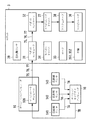
- FIG. 1 is a diagram showing an example of the overall configuration of the remote task execution system 5.
- FIG. 2 is a diagram illustrating an example of the first space 51, the second space 52, and the virtual space 53.
- the remote task execution system 5 shown in FIG. 1 is a system that allows the operator 40 to remotely perform tasks in the second space 52 shown in FIG. For example, the task of searching for the pen 61 and the panel 62 in the second space 52 and drawing a picture on the panel 62 with the pen 61 can be performed.
- the robot 3 is arranged in the second space 52, and the robot 3 directly handles various objects existing in the second space 52.
- the virtual space 53 is a virtual space in which the second space 52 is virtually reproduced by a computer.
- the avatar 41 of the operator 40 is arranged in the virtual space 53.
- the operator 40 can see the state of the virtual space 53 as viewed from the line of sight of the avatar 41 with the head mounted display 12. As a result, the user can feel that he / she has transferred to the avatar 41 and is in the virtual space 53.
- the avatar 41 When the operator 40 operates, the avatar 41 operates in the same manner, and the robot 3 also operates in conjunction therewith.
- the operator 40 can perform a task in the second space 52 remotely while being in the first space 51 and without being aware of the robot 3. it can.
- this mechanism will be described.
- the remote task execution system 5 includes an operation computer 10, a head mounted display 12, a plurality of color distance sensors 14, a motion capture computer 16, a communication line 2, a robot 3, and the like.
- the communication line 2 is a communication line such as an Ethernet (registered trademark) line, the Internet, a public line, or a dedicated line, and is used for various communication described later such as communication between the operation computer 10 and the robot 3.
- Ethernet registered trademark
- the communication line 2 is a communication line such as an Ethernet (registered trademark) line, the Internet, a public line, or a dedicated line, and is used for various communication described later such as communication between the operation computer 10 and the robot 3.
- the operator 40 is in the first space 51.
- the head mounted display 12 is attached to the head of the operator 40.
- a non-transmissive HMD As the head mounted display 12, a non-transmissive HMD, a transmissive HMD, or the like is used.
- An example of a non-transmissive HMD is Oculus lift from Oculus VR.
- Examples of transmissive HMDs are Microsoft's HoloLens and Google's Google Glass.
- a case where a non-transmissive HMD is used as the head mounted display 12 will be described as an example.
- the plurality of color distance sensors 14 are installed in the first space 51 so that the front surface, rear surface, and both side surfaces of an object arranged near the center of the first space 51 can be measured without blind spots.
- a case where three color distance sensors 141 to 143 are installed as the color distance sensor 14 will be described as an example.
- the robot 3 is in the second space 52. Further, various objects such as a pen 61 and a panel 62 are placed in the second space 52. A tag such as RFID (Radio Frequency Identification) is mounted on the placed object, and an environment in which the robot can read information on the object may be assumed.
- RFID Radio Frequency Identification
- a picture is drawn on the panel 62 with the pen 61.
- a white board is used as the panel 62, and a water-based pen is used as the pen 61.
- a capacitive touch panel display may be used as the panel 62. In this case, a touch pen is used as the pen 61.
- the operation computer 10 is installed in a place where it can communicate with the head mounted display 12 and the motion capture computer 16. It may be installed in the first space 51 or may be installed outside the first space 51.
- the motion capture computer 16 is installed in a place where it can communicate with the operation computer 10 and the color distance sensors 141-143. It may be installed in the first space 51 or may be installed outside the first space 51.
- FIG. 3 is a diagram illustrating an example of a hardware configuration of the operation computer 10.
- FIG. 4 is a diagram showing an example of the configuration of the task support program 10j.
- FIG. 5 is a diagram illustrating an example of the hardware configuration of the robot 3.
- each device constituting the remote task execution system 5 The main functions of each device constituting the remote task execution system 5 will be described. Details of processing of each device will be described later.
- the operation computer 10 mainly generates a command to the robot 3 based on the motion of the operator 40 or arranges the avatar 41 of the operator 40 in the virtual space 53 as shown in FIG. Generate image data for images.
- a personal computer is used as the operation computer 10 will be described as an example.
- the operation computer 10 includes a CPU (Central Processing Unit) 10a, a RAM (Random Access Memory) 10b, a ROM (Read Only Memory) 10c, an auxiliary storage device 10d, a wireless communication device 10e, a liquid crystal display 10f, The speaker 10g and the input device 10h are configured.
- a CPU Central Processing Unit
- RAM Random Access Memory
- ROM Read Only Memory
- the wireless communication device 10e communicates with the head mounted display 12, the motion capture computer 16, and the robot 3 via the wireless base station of the communication line 2.
- the liquid crystal display 10f displays a screen showing a message.
- the speaker 10g outputs a message by voice.
- the input device 10h is a keyboard or a pointing device, and is used by the operator 40 or the administrator to input data or commands to the operation computer 10.
- the task support program 10j is stored in the ROM 10c or the auxiliary storage device 10d.
- the task support program 10j is a program for showing the state of the virtual space 53 to the operator 40 and controlling the robot 3.
- the task support program 10j includes an initialization module 101, an avatar generation module 102, a virtual space calculation module 103, a movement information calculation module 104, a movement command module 105, a manipulation module 106, and a solution module 107. It consists of software modules. In this embodiment, the movement command module and the manipulate module are separated. However, when the robot 3 has redundant degrees of freedom, the movement base and the manipulator may be controlled as an integrated system.
- the initialization module 101 performs an initialization process before starting a task or restarting a task.
- the avatar generation module 102 generates data of the avatar 41 according to the measurement result of the three-dimensional shape of the operator 40.
- the virtual space calculation module 103 calculates the position and orientation of an object in the virtual space 53. Further, image data representing an image of the virtual space 53 when a specific direction is viewed from a specific position in the virtual space 53 is generated. Image data representing an image of the virtual space 53 when the avatar 41 is used as the virtual space 53 can also be generated. As a calculation and generation technique, SLAM (Simultaneous Localization And ⁇ Mapping) is used.
- SLAM Simultaneous Localization And ⁇ Mapping
- the movement information calculation module 104 calculates the amount and direction of movement based on the operation of the operator 40.
- the movement command module 105 generates a command for moving the robot 3 according to the operation of the operator 40 and gives it to the robot 3.
- the manipulate module 106 generates a command for operating the arm of the robot 3 according to the operation of the operator 40 and gives the command to the robot 3.
- the solution module 107 is a module for measures when the robot 3 encounters an obstacle.
- the task support program 10j is loaded into the RAM 10b and executed by the CPU 10a.
- An SSD Solid State Drive
- a hard disk is used as the auxiliary storage device 10d.
- the head mounted display 12 is mounted on the head of the operator 40 as described above. Then, image data is received from the operation computer 10 and an image representing the state of the virtual space 53 is displayed.
- the color distance sensors 141 to 143 are RGB-D cameras or depth cameras, and the color of each point on the surface of the human body of the operator 40 and the distance between each point and the color distance sensors 141 to 143 themselves are determined in advance. Measured every time Ta. Thereby, RGBD (Red
- the predetermined time Ta can be arbitrarily determined according to the level of analysis ability of the operation of the operator 40. For example, the predetermined time Ta is a time visited every 0.1 seconds.
- the color distance sensors 141 to 143 transmit the RGBD data to the motion capture computer 16 every time the RGBD data is obtained.
- the color distance sensors 141 to 143 for example, kinect sensors manufactured by Microsoft Corporation are used.
- the motion capture computer 16 converts the three-dimensional shape of the whole body of the operator 40 to the positions where the RGBD data and the color distance sensors 141 to 143 are installed. Calculate based on Then, the three-dimensional data indicating the calculated three-dimensional shape is transmitted to the operation computer 10.
- the motion capture computer 16 for example, a computer in which Microsoft's Kinect for Windows SDK is installed is used.
- the motion capture computer 16 calculates the three-dimensional shape of the whole body of the operator 40 every predetermined time Ta.
- the change in the three-dimensional shape represents the motion of the operator 40. Therefore, it can be said that the motion capture computer 16 is capturing the motion of the operator 40.
- the robot 3 includes a housing 30, a robot computer 31, a robot controller 32, a motor 33, a mobile driver 34, and two or four wheels 35, a manipulator 36, a manipulator driver 37, an actuator. 38, a color distance sensor 39, and the like.
- the robot computer 31 is a computer for performing overall management of the robot 3. For example, when specific data is received from the operation computer 10, it is transferred to the robot controller 32. Alternatively, the data obtained by the manipulator 36 is transferred to the operation computer 10.
- the robot computer 31 performs modeling of objects around the robot computer 31 based on the RGBD data obtained by the color distance sensor 39, and further calculates the position and orientation of the object.
- the robot computer 31 is built in the housing 30.
- the color distance sensor 39 is an RGB-D camera or a depth camera. As the color distance sensor 39, a Kinect sensor is used. The color distance sensor 39 is installed on the upper surface of the housing 30 so that the front of the robot 3 can be measured. In addition, you may install in positions other than the upper surface of the housing
- the robot controller 32 is built in the housing 30 and gives a command to the mobile driver 34 or the manipulator driver 37 so that the robot 3 moves according to the motion of the operator 40.
- the manipulator 36 grips and moves objects instead of human hands and arms.
- the manipulator 36 is provided on the upper surface of the housing 30 and includes an arm portion 361, a grip portion 362, and the like.
- the arm unit 361 has a linear motion joint and a rotary joint for giving the hand 6 degrees of freedom or more, and the position and posture can be changed by bending or extending these joints.
- the gripper 362 has a plurality of fingers, and can grip and release an object by adjusting the distance between the plurality of fingers.
- Actuator 38 drives arm portion 361 and gripping portion 362.
- the manipulator driver 37 controls the actuator 38 so that the arm unit 361 or the grip unit 362 is driven based on a command from the robot controller 32.
- the position of the grip portion 362 relative to the housing 30 is obtained by measuring the angle of each joint using, for example, a rotary encoder.
- the height of the upper surface of the housing 30 from the floor is about 50 to 100 centimeters.
- the length of the arm portion 361 is slightly longer than the length from the base of the human arm to the tip of the finger, and is about 60 to 100 centimeters.
- the distance when the fingers at both ends of the gripping part 362 are spread is slightly longer than the distance between the thumb and the little finger when the human hand is spread, and is about 20 to 30 centimeters.
- the gripping part 362 can move in the same range as the reach of the human hand when the human is standing at the same position as the robot 3 or in a wider range.
- the movable range of the operator 40 and the movable range of the robot 3 may be different.
- the CG Computer Graphics
- the operator 40 understands that the robot 3 cannot realize the task, and performs a recovery process to cope with it.
- One or two wheels 35 are provided on the right side surface and the left side surface of the housing 30.
- the case where the right wheel 351 and the left wheel 352 are provided as the wheels 35 on the right side surface and the left side surface of the housing 30 will be described as an example.
- the motor 33 is built in the housing 30 and drives the right wheel 351 and the left wheel 352.
- the mobile driver 34 is built in the housing 30 and controls the motor 33 so that the right wheel 351 and the left wheel 352 are driven based on a command from the robot controller 32. Thereby, the robot 3 moves.
- FIG. 6 is a diagram illustrating an example of a data flow at the time of initialization.
- FIG. 7 is a diagram illustrating an example of the positional relationship between the second spatial coordinate system and the robot coordinate system.
- the operator 40 stands with the right foot 403 and the left foot 404 aligned at a position surrounded by the color distance sensors 141 to 143 in the first space 51 before starting the task. Then, a start command 70 is input to the operation computer 10.
- the operation computer 10 performs initialization by the initialization module 101.
- initialization will be described with reference to FIG.
- the operation computer 10 transmits a measurement command 71 to the color distance sensors 141 to 143.
- the operator 40 may input the start command 70 using a wireless device, or an assistant may input the start command 70 instead of the operator 40.
- the measurement command 71 may be transmitted after a predetermined time, for example, 10 seconds elapses after the operator 40 inputs the start command 70.
- the operator 40 is stationary without moving until the initialization is completed.
- the color distance sensors 141 to 143 When receiving the measurement command 71, the color distance sensors 141 to 143 respectively start measuring the color of each point on the surface of the human body of the operator 40 and the distance between each point and the color distance sensors 141 to 143 themselves. The measurement is performed every predetermined time Ta as described above. The color distance sensors 141 to 143 transmit the RGBD data 7A to the motion capture computer 16 every time the RGBD data 7A is obtained by measurement.
- the motion capture computer 16 When the motion capture computer 16 receives the RGBD data 7A from each of the color distance sensors 141 to 143, the motion capture computer 16 calculates the three-dimensional shape of the whole body of the operator 40 based on the RGBD data 7A. Then, the three-dimensional data 7B indicating the calculated three-dimensional shape is transmitted to the operation computer 10.
- the operation computer 10 When receiving the first three-dimensional data 7B, the operation computer 10 detects the right hand 402, the right foot 403, and the left foot 404 from the three-dimensional shape indicated by the three-dimensional data 7B. Then, the position of the right hand 402 in the operator coordinate system is calculated. Hereinafter, this calculated position is referred to as “initial position P0”. In the case of work using both hands, not only the right hand 402 but also the position of the left hand 407 is detected.
- “Operator coordinate system” is a three-dimensional coordinate system as shown in FIG. That is, the center of the line 40L connecting the toes of the right foot 403 and the toes of the left foot 404 is the origin, the direction from the toes of the right foot 403 to the toes of the left foot 404 is the X1 axis direction, the vertically upward direction is the Z1 axis direction, , A three-dimensional coordinate system in which the direction perpendicular to the X1 axis and the Z1 axis and from the front to the back of the operator 40 is the Y1 axis.
- the operation computer 10 transmits an initialization command 72 indicating the initial position P0 as a parameter to the robot computer 31.
- the robot computer 31 When the robot computer 31 receives the initialization command 72, the robot computer 31 instructs the robot controller 32 to initialize the position of the grip portion 362. At this time, the robot controller 32 is notified of the initial position P0 indicated by the initialization command 72.
- the robot controller 32 instructs the manipulator driver 37 to move the grip 362 to a position in the robot coordinate system corresponding to the initial position P0.
- the center of the line connecting the positions where the right wheel 351 and the left wheel 352 contact each other is the origin
- the direction from the right wheel 351 to the left wheel 352 is the X4 axis direction
- the vertical upward direction is the Z4 axis.
- This is a three-dimensional coordinate system in which the direction is perpendicular to the X4 axis and the Z4 axis and the direction from the front to the back of the robot 3 is the Y4 axis.
- this center is referred to as “robot origin O4”.
- the robot controller 32 instructs the manipulator driver 37 to move the gripping part 362 to the position (X1a, Y1a, Z1a) in the robot coordinate system. To do.
- the robot controller 32 notifies the manipulator driver 37 of this position in the robot coordinate system.
- the manipulator driver 37 controls the actuator 38 so that the gripping part 362 moves to the notified position. Further, the manipulator driver 37 controls the actuator 38 so that the gripping part 362 is completely opened, that is, the distance between the fingers of the gripping part 362 is the longest possible distance. .
- the robot computer 31 causes the color distance sensor 39 to start measurement in front of the robot 3 in parallel with instructing the initialization of the position of the grip portion 362.
- the color distance sensor 39 performs measurement every predetermined time Ta, and transmits to the robot computer 31 every time the RGBD data 7C is obtained by measurement. Note that after initialization, measurement in front of the robot 3 and transmission of the RGBD data 7C may be performed only while the robot 3 is moving.
- the robot computer 31 transmits the RGBD data 7C to the operation computer 10 every time it receives the RGBD data 7C.
- the operation computer 10 determines the same position as the position of the robot origin O4 at the time of initialization in the second space 52 as the origin O2. Further, the direction from the right wheel 351 toward the left wheel 352 at this time is determined as the X2 axis direction. The vertical upward direction is defined as the Z2 axis direction. Then, a direction orthogonal to the X2 axis and the Z2 axis and extending from the front to the back of the robot 3 at this time is determined as the Y2 axis direction.
- a coordinate system composed of the X2 axis, the Y2 axis, and the Z2 axis is referred to as a “second spatial coordinate system”.
- the XYZ axes of the second spatial coordinate system that is, the X2 axis, the Y2 axis, and the Z2 axis are respectively the XYZ axes of the robot coordinate system, that is, the X4 axis, the Y4 axis, and Matches the Z4 axis.
- the robot 3 faces the minus direction of the Y2 axis and stops at the origin O2.
- the robot 3 moves in the second space 52, that is, the second spatial coordinate system, the position of the robot coordinate system with respect to the second spatial coordinate system is changed as shown in FIG. change.
- initialization by the initialization module 101 is completed.
- the avatar 41 and the robot 3 operate according to the operation of the operator 40. That is, the operator 40, the avatar 41, and the robot 3 are linked.
- the operator 40 it is felt that the avatar 41 moves with his / her movement, and the robot 3 moves autonomously with the movement of the avatar 41. Therefore, the operator 40 can handle the object in the second space 52 through the robot 3 without being aware of the robot 3 and without touching it directly.
- a process for displaying an image of the virtual space 53 and a process for moving the robot 3 are performed in parallel. Hereinafter, these processes will be described.
- FIG. 8 is a diagram illustrating an example of the angle ⁇ hip, the length Lleg, and the distance Dstep.
- FIG. 9 is a diagram illustrating an example of the data flow when the robot 3 moves.
- FIG. 10 is a diagram illustrating an example of the angle ⁇ body.
- FIG. 11 is a diagram illustrating an example of the moving direction and distance of the robot 3.
- the avatar 41 moves and the robot 3 also moves. Furthermore, the direction in which the robot 3 moves forward can be changed by changing the front direction of the robot. First, the process when the robot 3 moves forward will be described with reference to FIG. 8, taking as an example the case where the operator 40 steps. The movement of the avatar 41 will be described later. Processing in the case of walking in the first space 51 will also be described later.
- the operation computer 10 uses the movement information calculation module 104 to calculate the distance and direction to which the robot 3 should be moved as follows.
- the three-dimensional data 7B is transmitted from the motion capture computer 16 to the operation computer 10 every predetermined time Ta.
- the angle ⁇ hip between the right leg 405 and the left leg 406 of the operator 40 changes as follows.
- the angle ⁇ hip gradually increases from 0 degrees.
- the angle ⁇ hip becomes maximum.
- the angle ⁇ hip gradually decreases and returns to 0 degrees.
- the operation computer 10 determines whether or not the position of the right foot 403 or the left foot 404 has changed based on the three-dimensional data 7B, and if there is a change, the angle of each of the right leg 405 and the left leg 406 for each predetermined time Ta. ⁇ hip is calculated.
- the operation computer 10 calculates the length Lleg of the right leg 405 or the left leg 406 based on the three-dimensional data 7B. Note that the length Lleg need only be calculated once. It may be calculated in advance at the time of initialization.
- the operation computer 10 calculates the distance Dstep based on the following equation (1).
- the distance Dstep is a distance estimated to advance if the operator 40 walks instead of stepping.
- the operation computer 10 calculates the distance Dstep based on the change rate of the angle ⁇ hip at the length Lleg and the predetermined step time Ta.
- Time Ti is the i-th sample time, and time (Ti-1) is the previous time (before time Ta of time Ti).
- the operation computer 10 may calculate the distance Dstep by another method.
- the operation computer 10 may calculate the distance Dstep using a trigonometric function by assuming that the operator 40 has advanced one step as shown in FIG. 9B at the maximum angle ⁇ hip. According to this method, although the resolution is inferior to the method using equation (1), the amount of calculation can be reduced.
- This method also has a lower resolution than the method using equation (1), but can reduce the amount of calculation.
- the operation computer 10 calculates the change in the front direction of the operator 40 based on the three-dimensional data 7B as follows.
- the operation computer 10 continues to monitor the direction of the line 40L, that is, the line connecting the toe of the right foot 403 and the toe of the left foot 404 in the first space 51 after the initialization. Then, when the direction of the line 40L changes as shown in FIG. 10, the angle ⁇ body of the direction after the change with respect to the direction before the change is calculated. As a result, how much the operator 40 has changed the direction of his / her front is calculated.
- the distance and direction for moving the robot 3 are calculated by the movement information calculation module 104 as described above.
- the operation computer 10 may erroneously detect that the operator has stepped. Therefore, it is desirable for the operator 40 to change the direction with the right foot 403 and the left foot 404 attached to the floor. Alternatively, when the angle ⁇ hip is less than the predetermined angle, the operation computer 10 may not calculate the distance Dstep.
- the operation computer 10 gives a command to the robot computer 31 by the movement command module 105 as follows.
- the operation computer 10 transmits a forward command 73 indicating the distance Dstep as a parameter to the robot computer 31.
- a direction change command 74 indicating the angle ⁇ body as a parameter is transmitted to the robot computer 31.
- the robot computer 31 receives the forward command 73 or the direction change command 74 and transfers it to the robot controller 32.
- the robot controller 32 When the robot controller 32 receives the forward command 73 without receiving the direction change command 74 after initialization, the robot controller 32 instructs the mobile driver 34 to advance straight by the distance Dstep indicated by the forward command 73. Alternatively, when the forward command 73 is received without receiving the direction change command 74 after advancing one step in the previous time, the mobile driver 34 is instructed to go straight ahead by the distance Dstep indicated by the forward command 73. .
- the mobile driver 34 controls the motor 33 so that the robot 3 moves straight without changing the traveling direction by the distance Dstep as shown in FIG.
- the vehicle is advanced by the distance Dstep indicated by the forward command 73 in the direction of the angle ⁇ body indicated by the direction change command 74. To the mobile driver 34.
- the mobile driver 34 controls the direction of the right wheel 351 and the left wheel 352 and the motor 33 so that the robot 3 moves forward by the distance Dstep in the direction of the angle ⁇ body as shown in FIG.
- the mobile driver 34 calculates the current position and posture of the robot 3 in the second space 52 every predetermined time Ta while the robot 3 is moving, and a status indicating the calculated position and posture.
- Data 7D is transmitted to the robot computer 31.
- FIG. 12 is a diagram illustrating an example of the flow of data when an image of the state of the virtual space 53 is displayed.
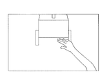
- FIG. 13 is a diagram illustrating an example of an image displayed on the head mounted display 12.
- the color distance sensors 141 to 143 continue to measure RGBD, and the motion capture computer 16 continues to calculate the three-dimensional shape.
- the three-dimensional data 7B is transmitted from the motion capture computer 16 to the operation computer 10 every predetermined time Ta.
- the operation computer 10 generates avatar data 7E of the avatar 41 by processing the 3D data 7B using the avatar generation module 102 every time the 3D data 7B is transmitted. For example, as processing, smoothing of a three-dimensional shape is performed.
- the motion capture computer 16 first calculates the three-dimensional shape of the operator 40 and generates the three-dimensional data 7B. After transmitting the three-dimensional data 7B to the operation computer 10, the motion capture computer 16 generates and transmits the three-dimensional data 7B. Instead of continuing the operation, the coordinates after the change of the point on the surface of the operator 40 may be notified to the operation computer 10.
- the operation computer 10 when the operation computer 10 is first notified of the changed coordinates, the operation computer 10 generates the avatar data 7E by correcting the three-dimensional data 7B according to the coordinates. Thereafter, each time the changed coordinates are notified, the avatar data 7E is corrected according to the coordinates.
- the RGBD data 7C is transmitted from the robot computer 31 to the operation computer 10 every predetermined time Ta. After initialization, status data 7D may be further transmitted.
- the operation computer 10 receives the RGBD data 7C, or performs the following processing by the virtual space calculation module 103 every time the avatar data 7E is generated or corrected.
- the operation computer 10 When the operation computer 10 receives the RGBD data 7C, the operation computer 10 reproduces the second space 52 based on the RGBD data 7C, thereby calculating the position and orientation of the virtual object in the virtual space 53. Thereby, each object in the second space 52 such as the pen 61 and the panel 62 is virtually imagined in the virtual space 53 while maintaining the relative relationship between the objects.
- the operation computer 10 may correct the position and orientation of the object according to the difference between the two.
- the operation computer 10 reproduces the second space 52 on the assumption that the robot 3 is at the origin O2 facing the minus direction of the Y2 axis. To do.
- the second space 52 is reproduced assuming that the robot 3 is at the position and orientation indicated by the status data 7D.
- the position and orientation can be calculated by Microsoft's kinect technology.
- the operation computer 10 matches the current position and orientation of the robot 3 in the second space 52 based on the avatar data 7E.
- the avatar 41 is arranged or moved in the virtual space 53.
- the initial position of the avatar 41 is the origin of the virtual space coordinate system.
- the virtual space coordinate system is a coordinate system of the virtual space 53, and the initial direction from the right toe to the left toe of the avatar 41 is the X3 axis direction, the vertical upward direction is the Z3 axis direction, and the X3 axis And a three-dimensional coordinate system in which the direction orthogonal to the Z3 axis and from the front to the back of the avatar 41 is the Y3 axis.
- the operation computer 10 updates the avatar 41 so that the three-dimensional shape shown in the avatar data 7E is obtained.
- the placement of the avatar 41 in the virtual space 53 and the update of the avatar 41 can be performed by a technique of SLAM (Simultaneous Localization And Mapping).
- SLAM Simultaneous Localization And Mapping
- the operation computer 10 detects the positions of both eyes of the avatar 41 in the virtual space 53 at every predetermined time Ta by the virtual space calculation module 103, and calculates the direction of the line of sight from that position.
- the position of both eyes of the avatar 41 in the virtual space 53 is referred to as “both eye positions”.
- the position of the head mounted display 12 may be detected as the position of both eyes.
- image data 7F representing an image of the state of the object in the virtual space 53 when the direction of the line of sight is viewed from both eye positions is generated and transmitted to the head mounted display 12. It can be said that this image shows the appearance of the operator 40 in the field of view.
- the head mounted display 12 displays an image represented by the image data 7F every time the image data 7F is received.
- the operator 40 when the operator 40 moves the face 401, the position of both eyes and the direction of the line of sight of the avatar 41 change along with the movement of the face 401, and the image of the state of the object in the virtual space 53 also changes. Therefore, the operator 40 can feel as if he / she is in the second space 52 or the virtual space 53 by looking at the image displayed every predetermined time Ta. Since the image changes every predetermined time Ta, it can be said that the head mounted display 12 displays a moving image.
- the displayed image is visible from the position of both eyes. Therefore, in these images, the entire avatar 41 is not shown, and only arms and hands are shown, for example, as shown in FIG.
- the image of the avatar 41 may be made translucent.
- the image of the avatar 41 may not be displayed.
- a transmissive HMD is used as the head mounted display 12
- the image of the avatar 41 is not displayed by default, and the image of the avatar 41 is displayed opaquely, translucently displayed, and non-transparent by a command.
- the display can be switched.
- FIG. 14 is a diagram illustrating an example of a data flow when the gripping unit 362 is operated.
- the operator 40 can move the grip 362 by moving the right hand 402.
- the process of moving the grip 362 will be described with reference to FIG.
- Operation computer 10 performs the following processing by manipulating module 106 after initialization.
- the operation computer 10 calculates the position of the right hand 402 in the operator coordinate system and monitors whether or not the position has changed.
- the operation computer 10 When detecting that the position of the right hand 402 has changed, the operation computer 10 transmits a manipulation command 75 indicating the coordinates of the latest position of the right hand 402 as a parameter to the robot computer 31.
- the robot computer 31 receives the manipulate command 75 and transfers it to the robot controller 32.
- the robot controller 32 instructs the manipulator driver 37 to move the gripping part 362 to the coordinate position indicated by the manipulate command 75 in the robot coordinate system.
- the manipulator driver 37 controls the actuator 38 so that the gripping part 362 moves by the amount of right hand movement.
- the gripping part 362 moves as the right hand 402 moves.
- the arm unit 361 may not move as the right arm of the operator 40 moves.
- the shape of the avatar 41 changes as the operator 40 changes the three-dimensional shape. Therefore, the right hand of the avatar 41 moves as the right hand 402 moves.
- the robot 3 also moves the grip portion 362 in the same manner. That is, the motion vectors of the right hand 402, the right hand of the avatar 41, and the gripping part 362 match each other.
- the right hand 402 may move even when the operator 40 steps on and changes his / her front direction. Then, the gripping part 362 is operated against the intention of the operator 40.
- the operation computer 10 may monitor the change in the position of the right hand 402 only when the right foot 403 and the left foot 404 are not moving.
- the operation computer 10 monitors the opening and closing of the finger of the right hand 402 as the position of the right hand 402 changes. If it is detected that the finger is closed, a close command 76 is transmitted to the robot computer 31. On the other hand, when it is detected that the finger is opened, an open command 77 is transmitted to the robot computer 31.
- the robot computer 31 receives the close command 76 and transfers it to the robot controller 32.
- the robot controller 32 When the robot controller 32 receives the close command 76, the robot controller 32 instructs the manipulator driver 37 to close the grip 362.
- the manipulator driver 37 controls the actuator 38 so that the distance between the plurality of fingers of the grip portion 362 is gradually shortened.
- a pressure-sensitive sensor may be attached to any of the fingers, and the operation of these fingers may be stopped when a certain pressure is detected by the pressure-sensitive sensor.
- the robot computer 31 instructs the manipulator driver 37 to open the grip portion 362.
- the manipulator driver 37 controls the actuator 38 so that the gripping part 362 is completely opened.
- the position of the grip portion 362 can be changed or the grip portion 362 can be closed or opened in accordance with the movement of the right hand 402.
- the operator 40 searches for the pen 61 and the panel 62 in the virtual space 53 while stepping in the first space 51, changing the direction, and looking at the image displayed on the head mounted display 12.
- the user tries to move near the pen 61 and the panel 62 while stepping on or changing the direction.
- the avatar 41 moves in the virtual space 53, and the robot 3 moves in the second space 52.
- the operator 40 extends the right hand 402 when the right hand 402 seems to reach the pen 61.
- the right hand 402 is closed. Then, the avatar 41 tries to grasp the pen 61. Further, in the second space 52, the robot 3 grips the pen 61 by the grip portion 362.
- the operator 40 moves the pen 61 to the surface of the panel 62 by moving the right hand 402, and when it seems that the tip of the pen 61 has touched the surface of the panel 62, the right hand 402 draws a circle. Move. It is also possible to present tactile sensation and force sensation to the operator using a haptex device. Then, the robot 3 moves the grip portion 362 according to the movement of the right hand 402. Thereby, a circle is drawn with the pen 61 on the surface of the panel 62.
- the image displayed on the head mounted display 12 is seen from the position of both eyes of the avatar 41. Therefore, the operator 40 can get into the virtual space 53 and move with his / her own leg and handle the object with his / her hand without being aware of the presence of the robot 3.
- the task of drawing a circle with a pen has been described as an example.
- a more complicated task such as an assembly operation or a processing operation, or a simple task such as a task of simply moving a specific part can be applied to the present invention. It is included in “task”.
- a task in which the operation of the robot does not appear visually is also included, such as the robot 3 taking a picture with the digital camera provided in the robot 3 in response to the operator 40 performing the gesture of cutting the shutter with the right hand 402.
- FIG. 15 is a diagram illustrating an example in which the virtual robot 3A is arranged in the virtual space 53 and the avatar 41 is shifted in order to change the viewpoint of the avatar 40 when dealing with an obstacle.
- FIG. 16 is a diagram illustrating an example of an image displayed on the head mounted display 12.
- FIG. 17 is a diagram illustrating an example of the flow of data when taking measures against an obstacle.
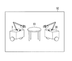
- FIG. 18 is a diagram illustrating an example in which the robot 3 and the help robot 3X cooperate.
- the robot 3 may encounter an obstacle while moving.
- the operator 40 and the avatar 41 can advance over the obstacle, but the robot 3 may not advance. Then, the robot 3 may not be able to follow the position where the avatar 41 is moved.
- the robot 3 can autonomously detour and move to the destination position of the avatar 41.
- the robot 3 may not be able to move to the destination position of the avatar 41 even if it uses a function of autonomously detouring. Therefore, the solution module 107 is used. According to the solution module 107, the robot 3 can get over the obstacle and retreat from the obstacle.
- the robot 3 When the robot 3 cannot move to the destination position of the avatar 41, the robot 3 notifies the operation computer 10 of the fact. Then, a message to that effect and image information are displayed on the head mounted display 12.
- the operator 40 When the operator 40 knows from the message or image information that the robot 3 does not move forward despite being stepped on, the operator 40 inputs the solution command 81.
- the mobile driver 34 may be made to detect that the vehicle does not move forward while continuing to receive the forward command 73. Then, the mobile driver 34 may transmit a failure notification signal 82 to the operation computer 10 via the robot computer 31.
- the operation computer 10 receives the failure information signal 82, the movement information calculation module 104, the movement command module 105, and the manipulation to disconnect the link between the operator 40 and the avatar 41 and the robot 3.
- the module 106 is stopped.
- the operation computer 10 uses the virtual space calculation module 103 to execute the object arrangement change process in the virtual space 53 as follows.
- the operation computer 10 places a virtual robot 3 ⁇ / b> A that virtualizes the three-dimensional shape of the robot 3 at a position corresponding to the current position of the robot 3 in the second space 52 in the virtual space 53. Deploy. The orientation of the virtual robot 3A is also matched with the current orientation of the robot 3.
- the operation computer 10 shifts the position where the avatar 41 is placed to a position just behind the virtual robot 3A by a predetermined distance.
- the virtual robot 3A is shifted rearward by 20 centimeters from the back surface.
- the three-dimensional data of the virtual robot 3A may be prepared in advance by measuring the robot 3 three-dimensionally.
- Robot CAD Computer-aided Design
- the operation computer 10 places the avatar 41 at the shifted position instead of the current position of the robot 3.
- the operation computer 10 After that, the operation computer 10 generates image data 7F of an image representing a state in which the line-of-sight direction is viewed from the positions of both eyes after the shift of the avatar 41, and transmits the image data 7F to the head mounted display 12.
- the head mounted display 12 displays an image represented by the image data 7F every time the image data 7F is received. However, since the position of the avatar 41 has shifted, an image of the environment as seen from behind the virtual robot 3A as shown in FIG. 16 is displayed.
- the operation computer 10 uses the solution module 107 to perform processing for causing the robot 3 to get over the obstacle and to retreat from the obstacle. Hereinafter, this process will be described with reference to FIG.
- the operator 40 confirms the state around the robot 3 by viewing the image. If the robot 3 is likely to get over the obstacle, the right hand 402 and the left hand 407 begin to extend forward in order to push the back of the robot 3.
- the operation computer 10 When the operation computer 10 detects that the right and left hands of the avatar 41 have reached the back of the virtual robot 3A, the operation computer 10 transmits an output up command 83 to the robot computer 31.
- the robot computer 31 receives the output up command 83 and transfers it to the robot controller 32.
- the robot controller 32 When the robot controller 32 receives the output up command 83, the robot controller 32 instructs the mobile driver 34 to increase the rotational speed higher than normal.
- the mobile driver 34 controls the motor 33 so that the right wheel 351 and the left wheel 352 rotate at a higher speed than usual or at a higher acceleration than usual.
- the robot 3 may or may not get over the obstacle.
- the robot 3 is a crawler type robot provided with a flipper, the angle of the flipper is adjusted according to the obstacle, and the obstacle is traversed.
- the rotation speed or acceleration of the right wheel 351 and the left wheel 352 may be increased in proportion to the speed at which the right hand 402 and the left hand 407 extend.
- the speed may be added to the output up command 83 as a parameter.
- the mobile driver 34 should just control the motor 33 so that the right wheel 351 and the left wheel 352 may rotate with the rotation speed or acceleration according to the parameter.
- the number of rotations or acceleration of the right wheel 351 and the left wheel 352 may be increased according to the speed at which the right hand 402 is bent.
- the operator 40 moves the right hand 402 to grab the housing 30 or the manipulator 36 and lower the robot 3 backward. Begin to stretch forward.
- the operator 40 closes the right hand 402 so as to grip the casing or manipulator, and starts bending the right hand 402 so as to pull the casing or manipulator toward him.
- the operation computer 10 transmits a back command 84 to the robot computer 31.
- the robot computer 31 receives the back command 84 and transfers it to the robot controller 32.
- the robot controller 32 When the robot controller 32 receives the back command 84, it instructs the mobile driver 34 to move backward.
- the mobile driver 34 controls the motor 33 so that the right wheel 351 and the left wheel 352 rotate in the reverse direction. Thereby, the robot 3 moves backward.
- the operator 40 may cause the avatar 41 to wrap around from the rear to the front of the virtual robot 3A by stepping on or changing the direction, and retreat the virtual robot 3A by pressing the front of the virtual robot 3A.
- the operator 40 inputs the resume command 78 to the operation computer 10 when the robot 3 can get over the obstacle or can move back to the robot 3.
- the operation computer 10 deletes the virtual robot 3A from the virtual space 53 and ends the processing of the solution module 107.
- the initialization module 101 performs the initialization process again.
- the avatar generation module 102, the virtual space calculation module 103, the movement information calculation module 104, the movement command module 105, and the manipulation module 106 are resumed.
- the operator 40 and the avatar 41 and the robot 3 are linked again, the operator 40 can immerse in the virtual space 53 and resume the target task.
- the data of the position and orientation of the object in the virtual space 53 calculated by the virtual space calculation module 103 before starting the solution module 107 may be reused without being deleted.
- the operation computer 10 operates the robot 3 by transmitting the output up command 83 or the back command 84 to the robot 3 according to the operation of the right hand 402 or the left hand 407.
- a help robot having a function equivalent to that of the robot 3 is dispatched to the position of the second space 52 corresponding to the position of the avatar 41, and the task of overcoming the obstacle and retreating from the obstacle to the help robot. It may be done.
- the operator 40 and the avatar 41 may be linked to the help robot instead of the robot 3. The link process is as described above.
- the help robot leaves the robot 3 after completing the role.
- the operation computer 10 uses the initialization module 101 to perform initialization processing again.
- the operator 40 can take measures against obstacles as if the operator 40 is immersed in the virtual space 53 and directly touches the robot 3 or the virtual robot 3A.
- the operation computer 10 may perform the obstacle countermeasure processing similarly when a specific event other than the encounter with the obstacle occurs. For example, the same processing may be performed when the gripping part 362 is not interlocked with the movement of the right hand 402 or when a panel for concealing the inside of the housing 30 is opened.
- the operation computer 10 may shift the avatar 41 forward, left, or right instead of behind the virtual robot 3A.
- the operation computer 10 and the robot computer robot controller 32 command the manipulator driver 37 to interlock the manipulator 36 with the operation. Also good.
- the help robot may appear autonomously and lift the object in cooperation with the help robot.
- the help robot 3X is activated, and the robot 3 and the help robot 3X cooperate as shown in FIG. Then, the chair 63 may be lifted.
- the means for calling the help robot 3X may be provided in the robot computer 31 or in the operation computer 10.
- the robot 3 alone or in cooperation with the help robot 3X may execute tasks such as assembly or processing as tasks.
- the help robot 3X may have a different structure from the robot 3.
- a drone with an arm may be used.
- the operation computer 10 executes processing according to the procedure shown in FIGS. 19 to 21 based on the task support program 10j.
- the operation computer 10 When the start command 70 is input, the operation computer 10 performs initialization as follows (# 801 to # 805).
- the operation computer 10 requests the color distance sensors 141 to 143 to start the RGBD measurement by the operator 40 by transmitting the measurement command 71 to the color distance sensors 141 to 143 (# 801).
- the motion capture computer 16 calculates the three-dimensional shape of the operator 40 based on the measurement result, and transmits the three-dimensional data 7B indicating the three-dimensional shape to the operation computer 10.
- the operation computer 10 starts receiving the three-dimensional data 7B (# 802).
- the operation computer 10 starts to detect the positions of the right hand 402, the right foot 403, the left foot 404, and the like of the operator 40 based on the three-dimensional data 7B (# 803).
- the operation computer 10 transmits an initialization command 72 to the robot 3 (# 804). Then, the robot 3 starts to measure RGBD in the second space 52, and the operation computer 10 starts to receive the RGBD data 7C from the robot 3 (# 805). Note that after initialization, status data 7D is also received.
- the operation computer 10 gives a movement-related command to the robot 3 as follows according to the operation of the operator 40 (# 821 to # 828).
- the operation computer 10 monitors the change in the position of the right foot 403 or the left foot 404 (# 821), and each time the change is detected (Yes in # 822), calculates the distance Dstep (# 823), and uses the distance Dstep as a parameter. Is transmitted to the robot 3 (# 824).
- the operation computer 10 monitors the change in the direction of the operator 40 (# 825), and when the change is detected (Yes in # 826), calculates the angle ⁇ hip (# 827), and indicates the angle ⁇ hip as a parameter.
- the conversion command 74 is transmitted to the robot 3 (# 828 in FIG. 20).
- the operation computer 10 performs the processing related to the virtual space 53 as follows (# 841 to # 845).
- the operation computer 10 virtualizes the virtual space 53 by reproducing the second space 52 based on the RGBD data 7C and the status data 7D (# 841). Each time the RGBD data 7C and the status data 7D are obtained, the reproduction range is expanded.
- the avatar 41 is generated or corrected based on the operation computer 10 and the three-dimensional data 7B (# 842). Then, the avatar 41 is arranged in the virtual space 53 (# 843). In addition, when the avatar 41 has already been arrange
- the operation computer 10 generates an image representing the state of the virtual space 53 viewed from the position of both eyes of the avatar 41 (# 844), and transmits the image data 7F of the image to the head mounted display 12 (# 845). Thereby, an image is displayed on the head mounted display 12.
- the operation computer 10 performs processing for operating the grip portion 362 as follows (# 861 to # 863).
- the operation computer 10 monitors the change in the position of the right hand 402 and the opening and closing of the finger (# 861). If a change is detected (Yes in # 862), a command corresponding to the change is transmitted to the robot 3 (# 863). Specifically, when a change in the position of the right hand 402 is detected, a manipulation command 75 indicating the amount of change as a parameter is transmitted. When it is detected that the finger is closed, a close command 76 is transmitted. When it is detected that the finger is opened, an open command 77 is transmitted.
- steps # 821 to # 824, the processes of steps # 825 to # 828, the processes of steps # 841 to # 845, and the processes of steps # 861 to # 863 are appropriately performed in parallel.
- the operation computer 10 performs the processing for countermeasures against the obstacle as follows (# 872 to ##). 881).
- the operation computer 10 cuts the link between the operator 40 and the avatar 41 and the robot 3 (# 872), and moves the virtual robot to a position in the virtual space 53 corresponding to the current position of the robot 3 in the second space 52.
- 3A is arranged (# 873).
- the orientation of the virtual robot 3A is also matched with the current orientation of the robot 3.
- the avatar 41 is shifted to the rear of the virtual robot 3A (# 874 in FIG. 21).
- the operation computer 10 generates image data 7F of an image representing a state in which the line of sight is viewed from both eye positions after the avatar 41 is shifted (# 875), and transmits the image data 7F to the head mounted display 12 (# 876).
- the operation computer 10 monitors the position of a part such as the right hand of the avatar 41 (# 877). When it is detected that the part of the avatar 41 touches a specific part of the virtual robot 3A (# 878), a command corresponding to the subsequent operation of the part of the avatar 41 is transmitted to the robot 3 (# 879).
- the operation computer 10 sends the output up command 83 to the robot 3 Send to.
- the operation computer 10 transmits a back command 84 to the robot 3.
- the operation computer 10 deletes the virtual robot 3A from the virtual space 53 (# 881), returns to step # 801, and performs initialization again.
- the operator 40 is immersed in the virtual space 53 as if he / she was transferred to the avatar 41, and without being aware of the existence of the robot 3 having a structure different from that of the human body, Tasks in the second space 52 can be performed.
- each unit of the remote task execution system 5 may perform processing as follows.
- the movement information calculation module 104 of the operation computer 10 determines the initial position of the operator 40 as the origin of the first spatial coordinate system.
- the X1 ′ axis, Y1 ′ axis, and Z1 ′ axis (see FIG. 2) of the first spatial coordinate system coincide with the X1 axis, Y1 axis, and Z1 axis of the operator coordinate system, respectively.
- the operator coordinate system also moves with respect to the first spatial coordinate system.
- the movement information calculation module 104 calculates the coordinates of the position of the operator 40 in the first spatial coordinate system based on the values obtained by the color distance sensors 141 to 143 or the values obtained by the position sensor.
- the avatar generation module 102 moves the avatar 41 to the position of the coordinates calculated by the movement information calculation module 104 in the virtual space coordinate system.
- the movement command module 105 instructs the robot 3 to move to the position of the coordinates calculated by the movement information calculation module 104 in the second virtual space coordinate system. Then, the robot 3 moves according to a command from the movement command module 105.
- the stepping mode and the walking mode may be prepared in the operation computer 10.
- the operation computer 10 moves the avatar 41 and the robot 3 in response to the stepping.
- the operation computer 10 moves to the position of the operator 40 in the first spatial coordinate system.
- the avatar 41 and the robot 3 may be moved accordingly.
- FIG. 22 is a diagram illustrating an example of the first space 51, the second space 52, and the virtual space 53 when the power assist suit 300 is a control target.
- FIG. 23 is a diagram illustrating a second example of the first space 51, the second space 52, and the virtual space 53 when the power assist suit 300 is a control target.
- the link between the operator 40 and the avatar 41 and the robot 3 is disconnected, and the obstacle is moved over the robot 3 according to the operation of the operator 40 by the solution module 107. Or retreated from the obstacle.
- the operator 40 was able to move the robot 3 in such a manner as to immerse in the virtual space 53 and touch the robot 3 or the virtual robot 3A directly.
- the processing by the solution module 107 may be applied to operate other objects in the second space 52.
- it may be applied to operate the power assist suit 300.
- the power assist suit 300 is a power assist suit that supports the lower limbs, such as Cyberdyne's HAL (Hybrid Assistive Limb) medical lower limb type or HAL welfare lower limb type, and the operator 40 plays golf as an expert.
- HAL Hybrid Assistive Limb
- HAL welfare lower limb type a power assist suit that supports the lower limbs
- the operator 40 plays golf as an expert.
- the configuration of each element of the remote task execution system 5 will be described by taking as an example the case where the person 46 who is a beginner is instructed to operate the lower body in the case of the swing. The description overlapping with the above configuration is omitted.
- a plurality of color distance sensors 39A to 39C are arranged.
- the person 46 wears the power assist suit 300 and stands in the second space 52.
- the color distance sensors 39A to 39C measure RGBD of the person 46 and surrounding objects, and transmit the measurement results to the operation computer 10.
- the virtual computer 53 reproduces the second space 52 based on these measurement results by the virtual space calculation module 103, thereby virtualizing the virtual space 53.
- the avatar 47 of the person 46 appears in the virtual space 53 in a state where the power assist suit 300 is worn.
- the power assist suit 300 appearing in the virtual space 53 is referred to as “virtual power assist suit 301”.
- the operation computer 10 generates the avatar 41 by the avatar generation module 102, and arranges the avatar 41 at a position away from the back of the avatar 47 in the virtual space 53 by a predetermined distance by the virtual space calculation module 103. For example, it arrange
- the three-dimensional data of the virtual power assist suit 301 may be prepared in advance by measuring the power assist suit 300 three-dimensionally. And you may arrange
- the operation computer 10 After arranging the avatar 41 and the avatar 47 in the virtual space 53, the operation computer 10 generates image data 7 ⁇ / b> F of an image in which the virtual space 53 is viewed from the position of both eyes of the avatar 41 in the line of sight, and the head mounted display 12 to send.
- the head mounted display 12 displays an image based on the image data 7F. As a result, the operator 40 can feel as if he is behind the person 46.
- General power assist suits operate in response to biological potential signals.
- the power assist suit 300 is provided with a wireless LAN device, and is configured to operate according to a command transmitted from the operation computer 10 instead of a biological potential signal.
- Control of power assist suit 300 The operator 40 can operate the power assist suit 300 as if touching the virtual power assist suit 301.
- the operator 40 confirms the form of the person 46 by viewing the image. If you find a problem with the movement of your lower body, have the person 46 swing slowly. At this time, how to move the lower body is instructed by moving the right hand 402 and the left hand 407 so as to move the power assist suit 300 in direct contact.
- the operation computer 10 detects that the right hand and the left hand of the avatar 41 and the virtual power assist suit 301 are in contact with each other in the virtual space 53
- the operation computer 86 displays an operation command 86 indicating the subsequent movements of the right hand 402 and the left hand 407 as parameters. It transmits to the power assist suit 300.
- the detection of the contact and the transmission of the operation command 86 may be performed by the manipulate command module 106, for example. Alternatively, a module different from the manipulate command module 106 may be prepared and used.
- the power assist suit 300 When the power assist suit 300 receives the operation command 86, the power assist suit 300 operates according to the operation indicated by the operation command 86.
- the operator 40 finds the problem that the right knee of the person 46 is stretched, the operator 40 holds the right knee of the virtual power assist suit 301 or a part near the right hand as if bending the right knee of the person 46. 402 and left hand 407 are moved. Then, an operation command 86 indicating this movement as a parameter is transmitted from the operation computer 10 to the power assist suit 300.
- the power assist suit 300 operates according to the movement indicated by the operation command 86.
- the operator 40 if the operator 40 thinks that there is a problem with how to twist the waist of the person 46, the operator 40 holds the waist portion of the virtual power assist suit 301 and twists the waist of the person 46 with the correct twisting method. And move the left hand 407. Then, an operation command 86 indicating this movement as a parameter is transmitted from the operation computer 10 to the power assist suit 300.
- the power assist suit 300 operates according to the movement indicated by the operation command 86.
- control method of the power assist suit 300 is merely an example. For example, by experimentally determining which potential signal is generated by moving which part of the power assist suit 300 with both hands in advance, the relationship between the movement of both hands, the part of the power assist suit 300, and the potential signal is determined.
- the data shown may be registered in the database.
- the operation computer 10 calculates a potential signal based on the contacted part, the movements of the right hand 402 and the left hand 407, and this data, and the power assist suit 300 May be notified.
- the power assist suit 300 operates based on the notified potential signal.
- the operator 40 can instruct the person 46 in a form more safely than before in real time while being away from the person 46.
- a power assist suit that supports the upper body may be used.
- this modification can be applied to convey techniques other than golf swing. For example, it can also be applied to the succession of craftsmanship techniques such as pottery, architecture, or sculpture, or performing arts such as dance, drama, or calligraphy.
- This modification can also be applied to machines other than the power assist suit 300.
- the present invention can be applied to a vehicle having an automatic driving function.
- the operator 40 may also wear the power assist suit 302 as shown in FIG.
- the power assist suit 302 notifies the power assist suit 300 when detecting the operation of the operator 40. Then, the power assist suit 300 operates according to the operation of the operator 40.
- the power assist suit 300 may notify the power assist suit 302 when the motion of the person 46 is detected.
- the power assist suit 302 may operate according to the operation of the person 46. As a result, the operator 40 can experience the motion of the person 46 and determine whether the motion of the person 46 is wrong or good.
- the initialization module 101 to the solution module 107 are software modules. However, all or part of these modules may be realized by hardware modules.
- the three-dimensional shape of the operator 40 is calculated by the color distance sensor 14 and RGBD by the motion capture computer 16, but may be measured by a three-dimensional measuring device.
- the case where the grip portion 362 grips the pen 61 has been described as an example.
- the robot 3 may move the auxiliary robot to the robot 3 and lift or move the object in cooperation with the auxiliary robot.
- the operator 40 inputs the solution command 81 when the robot 3 does not advance as intended, but it may be input at any time. For example, it may be input when it is desired to check the state of the robot 3.
- the operator 40 can easily check portions that are difficult to check when the operator 40 and the avatar 41 are linked to the robot 3 such as the wheels 35 and the manipulator 36.
- the operation computer 10 when the operator 40 and the avatar 41 are linked to the robot 3, the operation computer 10 does not place the virtual robot 3 ⁇ / b> A in the virtual space 53, but to confirm the state of the robot 3.
- the arrangement may be made temporarily or until a cancellation command is inputted. Thereby, the operator 40 can confirm whether the right hand 402 and the holding part 362 are interlock
- the state of the second space 52 is transmitted to the operator 40 by the image of the virtual space 53, but the state may be transmitted by other means.
- a contact sound may be output from the speaker 10g of the operation computer 10.
- the contact with the obstacle may be detected by the sensor of the robot 3. Alternatively, detection may be performed based on the position of the robot 3 and the position of the object calculated by the virtual space calculation module 103.
- the contact sound may be a sound that is recorded or synthesized in advance, or may be a sound that is collected when the robot 3 is actually contacted with a microphone.
- a message indicating contact may be displayed by the color distance sensor 14 or the liquid crystal display 10f.
- a state in which the obstacle is broken may be displayed by the color distance sensor 14.
- a force sensor is provided on the finger of the grip portion 362 to measure the force or moment when the object is gripped.
- a tactile sensor is provided in the grip portion 362 to detect a slipping feeling or a rough feeling of an object. Then, the operation computer 10 displays the measurement result or the detection result on the head mounted display 12 or the liquid crystal display 10f.
- a tactile glove may be fitted to the right hand 402 of the operator 40, and the sense of grasping the object may be transmitted to the operator 40 by the tactile glove based on the measurement result or the detection result.
- the tactile glove Dexmo from Dexa Robotics or Senso Glove from Senso Devices is used.
- the robot 3 can also be used in a disaster site, an accident site, or outer space.
- the avatar 41 moves immediately in accordance with the movement of the operator 40, but there may be a time difference between the movement of the avatar 41 and the movement of the robot 3.
- the robot 3 operates on the moon surface after the time required for reaching the command has elapsed.
- the operation speed of the robot 3 is slower than the operation speed of the avatar 41
- the robot 3 operates with a delay from the movement of the operator 40 or the avatar 41.
- the robot 3 lifts the chair with a delay due to the time required for the movement. In this case, a log of the operation of the operator 40 is saved, and the robot 3 is controlled based on the log.
- the motion of the robot 3 is simulated by the physical simulator, and the operator 40 and the avatar 41 are operated in synchronization in the virtual space using the simulation result. Then, data indicating the movement of the avatar 41 is stored in a memory and is sequentially transmitted to the robot 3. If the robot 3 on the simulator or the robot 3 in the real space fails in the work, the operator 40 is notified of this, and the state of the avatar 41 is returned to the state immediately before the work fails by the data in the memory. The recovery operation can be started by returning the space status.
- the case where the robot 3 is provided with two wheels 35 as moving means has been described as an example, but four or six wheels 35 may be provided.
- a caterpillar may be provided.
- a screw may be provided at the bottom of the robot 3 so that the robot 3 can move on or under water.
- Various robots may be prepared, and different robots may be used depending on the situation at the disaster site or the accident site.
- the gripping part 362 of the robot 3 is interlocked with the operation of the right hand 402 of the operator 40.
- the gripping part 362 of the right manipulator 36 is connected to the right hand of the operator 40.
- the handle 362 of the left manipulator 36 may be linked to the left hand 407 of the operator 40.
- the right foot and the left foot of the robot may be linked to the right foot 403 and the left foot of the operator 40, respectively.
- the avatar 41 is arranged in the virtual space 53 without being enlarged or reduced, but may be enlarged or reduced.
- the robot 3 is about the same size as a small animal such as a mouse
- the avatar 41 may be reduced and arranged in accordance with this size.
- the avatar 41 and the robot 3 may be moved in accordance with the size ratio of the avatar 41 to the size of the operator 40 in the movement of the operator 40.
- you may change the scale of the movement of the avatar 41 and the robot 3 according to the ratio, without changing the magnitude
- the robot 3 detects an object existing in the second space 52 based on the RGBD data 7C obtained by the color distance sensor 39 and the like.
- an IC (Integrated Circuit) tag that records the position, three-dimensional shape, characteristics, and the like of each object may be attached to each object, and detection may be performed by reading these pieces of information from the IC tag.
- FIG. 24 is a diagram illustrating an example of experimental results.
- the operator 40 moves the robot 3 closer to the panel 62 by stepping on the spot.
- the operator 40 feels that the right hand 402 reaches the panel 62, the operator 40 moves the pen 61 on the panel 62 so as to trace a circle drawn in advance.
- the right hand 402 is moved by applying.
- the virtual robot 3A is arranged in the virtual space 53 so that the operator 40 can easily grasp the position of the grip portion of the virtual robot 3A.
- the virtual robot 3 ⁇ / b> A is arranged on the 23-inch general liquid crystal display without arranging the avatar 41 in the virtual space 53, and an image representing the state of the virtual space 53 is displayed.
- the subject that is, the operator 40 operated the robot 3 using a game controller having a stick and a button while viewing this image.
- the viewpoint of viewing the displayed image that is, the virtual space 53 can be freely changed at any time by the operator 40 with the mouse.
- a circle drawn in advance by the game controller is traced with the pen 61.
- the present invention is used for an operator to remotely work or communicate to a beginner of skilled skills via a machine such as a robot.
- Remote task execution system (robot control system, machine control system) 10a CPU 10b RAM 10h Speaker (notification means) 103 Virtual space calculation module (display means) 104 Movement information calculation module (second control means) 105 Movement command module (second control means) 106 Manipulate command module (control means) 107 Solution module (third control means) 12 Head-mounted display (display) 3 Robot 3A Virtual Robot 362 Gripping part (first part) 300 Power assist suit (machine) 40 Operator 402 Right hand (second part) 41 Avatar 52 Second space (space) 53 Virtual space 61 Pen (object) 63 Chair (object)
Landscapes
- Engineering & Computer Science (AREA)
- Theoretical Computer Science (AREA)
- Physics & Mathematics (AREA)
- General Physics & Mathematics (AREA)
- General Engineering & Computer Science (AREA)
- Mechanical Engineering (AREA)
- Robotics (AREA)
- Software Systems (AREA)
- Human Computer Interaction (AREA)
- Computer Hardware Design (AREA)
- Computer Graphics (AREA)
- Radar, Positioning & Navigation (AREA)
- Remote Sensing (AREA)
- Aviation & Aerospace Engineering (AREA)
- Automation & Control Theory (AREA)
- Educational Technology (AREA)
- Educational Administration (AREA)
- Business, Economics & Management (AREA)
- Manipulator (AREA)
- Processing Or Creating Images (AREA)
- User Interface Of Digital Computer (AREA)
Abstract
La présente invention concerne un affichage d'ordinateur d'exploitation, sur un dispositif d'affichage tel qu'un visiocasque, une image de champ de vision montrant l'état qui apparaît dans le champ de vision d'un opérateur si l'opérateur qui se trouve dans un premier espace apparaît dans un second espace dans lequel un robot est présent. Le robot est commandé de telle sorte que le robot réalise une tâche conformément aux opérations effectuées par l'opérateur.
Priority Applications (4)
| Application Number | Priority Date | Filing Date | Title |
|---|---|---|---|
| JP2018552962A JP6940879B2 (ja) | 2016-11-24 | 2017-11-24 | ロボット制御システム、機械制御システム、ロボット制御方法、機械制御方法、およびコンピュータプログラム |
| EP17873066.9A EP3547267A4 (fr) | 2016-11-24 | 2017-11-24 | Système de commande de robot, système de commande de machine, procédé de commande de robot, procédé de commande de machine et support d'enregistrement |
| CN201780072485.7A CN109983510A (zh) | 2016-11-24 | 2017-11-24 | 机器人控制系统、机械控制系统、机器人控制方法、机械控制方法和记录介质 |
| US16/422,489 US20190278295A1 (en) | 2016-11-24 | 2019-05-24 | Robot control system, machine control system, robot control method, machine control method, and recording medium |
Applications Claiming Priority (2)
| Application Number | Priority Date | Filing Date | Title |
|---|---|---|---|
| JP2016-227546 | 2016-11-24 | ||
| JP2016227546 | 2016-11-24 |
Related Child Applications (1)
| Application Number | Title | Priority Date | Filing Date |
|---|---|---|---|
| US16/422,489 Continuation US20190278295A1 (en) | 2016-11-24 | 2019-05-24 | Robot control system, machine control system, robot control method, machine control method, and recording medium |
Publications (1)
| Publication Number | Publication Date |
|---|---|
| WO2018097223A1 true WO2018097223A1 (fr) | 2018-05-31 |
Family
ID=62196236
Family Applications (1)
| Application Number | Title | Priority Date | Filing Date |
|---|---|---|---|
| PCT/JP2017/042155 WO2018097223A1 (fr) | 2016-11-24 | 2017-11-24 | Système de commande de robot, système de commande de machine, procédé de commande de robot, procédé de commande de machine et support d'enregistrement |
Country Status (5)
| Country | Link |
|---|---|
| US (1) | US20190278295A1 (fr) |
| EP (1) | EP3547267A4 (fr) |
| JP (1) | JP6940879B2 (fr) |
| CN (1) | CN109983510A (fr) |
| WO (1) | WO2018097223A1 (fr) |
Cited By (7)
| Publication number | Priority date | Publication date | Assignee | Title |
|---|---|---|---|---|
| JP2020102184A (ja) * | 2018-12-19 | 2020-07-02 | 国立臺北科技大學 | 加工制御システム及び加工制御方法 |
| DE102019109740A1 (de) * | 2019-04-12 | 2020-10-15 | Volkswagen Aktiengesellschaft | Fahrzeugfensterscheibeneinrichtung und Verfahren zum Betreiben einer Fahrzeugfensterscheibeneinrichtung |
| WO2020235541A1 (fr) * | 2019-05-20 | 2020-11-26 | 国立大学法人東京大学 | Dispositif d'interface d'image, dispositif de manipulation d'image, dispositif de manipulation d'objet de manipulation, système de manipulation d'objet de manipulation, procédé de présentation d'objet de manipulation et programme de présentation d'objet de manipulation |
| WO2021166973A1 (fr) * | 2020-02-19 | 2021-08-26 | ファナック株式会社 | Système d'exploitation pour machines industrielles |
| JP6933849B1 (ja) * | 2020-09-03 | 2021-09-08 | 株式会社Abal | 体感型インターフェースシステム、及び、動作体感システム |
| CN113631325A (zh) * | 2019-03-29 | 2021-11-09 | 株式会社Ihi | 远程操作装置 |
| JP2023507241A (ja) * | 2019-12-31 | 2023-02-21 | ヒューマン モード、エルエルシー | 随意のデュアルレンジ運動学を用いたプロキシコントローラスーツ |
Families Citing this family (13)
| Publication number | Priority date | Publication date | Assignee | Title |
|---|---|---|---|---|
| US10427305B2 (en) * | 2016-07-21 | 2019-10-01 | Autodesk, Inc. | Robotic camera control via motion capture |
| US10901687B2 (en) * | 2018-02-27 | 2021-01-26 | Dish Network L.L.C. | Apparatus, systems and methods for presenting content reviews in a virtual world |
| US11538045B2 (en) | 2018-09-28 | 2022-12-27 | Dish Network L.L.C. | Apparatus, systems and methods for determining a commentary rating |
| US10692294B1 (en) * | 2018-12-17 | 2020-06-23 | Universal City Studios Llc | Systems and methods for mediated augmented physical interaction |
| CN110465956B (zh) * | 2019-07-31 | 2022-04-01 | 东软集团股份有限公司 | 一种车辆机器人、车机、方法及机器人系统 |
| CN110347163B (zh) * | 2019-08-07 | 2022-11-18 | 京东方科技集团股份有限公司 | 一种无人驾驶设备的控制方法、设备及无人驾驶控制系统 |
| US11461867B2 (en) * | 2019-09-19 | 2022-10-04 | Sanctuary Cognitive Systems Corporation | Visual interface and communications techniques for use with robots |
| CN114761180A (zh) * | 2019-12-13 | 2022-07-15 | 川崎重工业株式会社 | 机器人系统 |
| CN111026277A (zh) * | 2019-12-26 | 2020-04-17 | 深圳市商汤科技有限公司 | 一种交互控制方法及装置、电子设备和存储介质 |
| CN111716365B (zh) * | 2020-06-15 | 2022-02-15 | 山东大学 | 基于自然行走的沉浸式远程交互系统及方法 |
| CN111833669B (zh) * | 2020-07-13 | 2022-07-22 | 孙学峰 | 一种中国书法用笔教学系统及教学方法 |
| CN112526983B (zh) * | 2020-09-11 | 2022-10-28 | 深圳银星智能集团股份有限公司 | 一种机器人的路径规划方法、主控芯片及机器人 |
| EP4198691A1 (fr) * | 2021-12-15 | 2023-06-21 | Deutsche Telekom AG | Procédé et système de téléopération à réalité mixte par vision stéréoscopique à distance |
Citations (3)
| Publication number | Priority date | Publication date | Assignee | Title |
|---|---|---|---|---|
| JPH05228855A (ja) | 1992-02-19 | 1993-09-07 | Yaskawa Electric Corp | テレイグジスタンス視覚装置 |
| JPH06323094A (ja) | 1993-05-11 | 1994-11-22 | Kajima Corp | 仮想現実感を用いた遠隔操作システム |
| JP2015077354A (ja) * | 2013-10-18 | 2015-04-23 | 国立大学法人 和歌山大学 | パワーアシストロボット装置 |
Family Cites Families (8)
| Publication number | Priority date | Publication date | Assignee | Title |
|---|---|---|---|---|
| US7626571B2 (en) * | 2005-12-22 | 2009-12-01 | The Board Of Trustees Of The Leland Stanford Junior University | Workspace expansion controller for human interface systems |
| CN100591202C (zh) * | 2008-05-05 | 2010-02-24 | 江苏大学 | 柑橘采摘机器人的柔性采摘装置和方法 |
| US9256282B2 (en) * | 2009-03-20 | 2016-02-09 | Microsoft Technology Licensing, Llc | Virtual object manipulation |
| CN103459099B (zh) * | 2011-01-28 | 2015-08-26 | 英塔茨科技公司 | 与一个可移动的远程机器人相互交流 |
| JP5613126B2 (ja) * | 2011-09-09 | 2014-10-22 | Kddi株式会社 | 画面内の対象が押圧によって操作可能なユーザインタフェース装置、対象操作方法及びプログラム |
| KR101978740B1 (ko) * | 2012-02-15 | 2019-05-15 | 삼성전자주식회사 | 원격조종시스템 및 그 제어방법 |
| US9283674B2 (en) * | 2014-01-07 | 2016-03-15 | Irobot Corporation | Remotely operating a mobile robot |
| WO2016025941A1 (fr) * | 2014-08-15 | 2016-02-18 | University Of Central Florida Research Foundation, Inc. | Interface de commande pour système d'avatar d'humanoïde robotique, et procédés associés |
-
2017
- 2017-11-24 EP EP17873066.9A patent/EP3547267A4/fr not_active Withdrawn
- 2017-11-24 WO PCT/JP2017/042155 patent/WO2018097223A1/fr unknown
- 2017-11-24 CN CN201780072485.7A patent/CN109983510A/zh not_active Withdrawn
- 2017-11-24 JP JP2018552962A patent/JP6940879B2/ja active Active
-
2019
- 2019-05-24 US US16/422,489 patent/US20190278295A1/en not_active Abandoned
Patent Citations (3)
| Publication number | Priority date | Publication date | Assignee | Title |
|---|---|---|---|---|
| JPH05228855A (ja) | 1992-02-19 | 1993-09-07 | Yaskawa Electric Corp | テレイグジスタンス視覚装置 |
| JPH06323094A (ja) | 1993-05-11 | 1994-11-22 | Kajima Corp | 仮想現実感を用いた遠隔操作システム |
| JP2015077354A (ja) * | 2013-10-18 | 2015-04-23 | 国立大学法人 和歌山大学 | パワーアシストロボット装置 |
Non-Patent Citations (7)
| Title |
|---|
| "Aiming for efficiency on part with experts", REALIZING AUTONOMOUS CONTROL AND VIRTUAL REALITY, vol. 1162, pages 28 - 35 * |
| A. KHEDDAR: "Teleoperation based on the hidden robot concept", SYSTEMS, MAN AND CYBERNETICS, PART A: SYSTEMS AND HUMANS, IEEE TRANSACTIONS ON, vol. 31, no. 1, 13 January 2001 (2001-01-13), XP011056372 |
| C. HAS. PARKJ. HERI. JANGY. LEEG. R. CHOH. I. SO ND. LEE: "IEEE International Conference on Robotics and Automation (ICRA", 26 May 2015, IEEE, article "Whole body multi-modal semi-autonomous teleoperation system of mobile manipulator" |
| C. L. FERNANDOM. FURUKAWAT. KUROGIS. KAMUROK. SATOK. MINAMIZAWAS. TACHI: "Intelligent Robots and Systems (IROS), 2012 IEEE/RSJ International Conference on", 2012, IEEE, article "Design of TELESAR V for transferring bodily consciousness in telexistence", pages: 5112 - 5118 |
| FERNANDO, C. L. ET AL.: "Design of TELESAR V for Transferring Bodily Consciousness in Telexistence", IEEE /RSJ INTERNATIONAL CONFERENCE ON INTELLIGENT ROBOTS AND SYSTEMS, 2012, pages 5112 - 5118, XP032287660 * |
| HIRAIWA, AKIRA ET AL.: "Tele-operation Human Interface for Mobile Tele-existence and Proposal of Tele-collaboration with Tele-robotics", PROCEEDINGS OF THE 21ST ANNUAL CONFERENCE OF THE RSJ, vol. 21, 2003, pages 95, XP009518002 * |
| See also references of EP3547267A4 * |
Cited By (11)
| Publication number | Priority date | Publication date | Assignee | Title |
|---|---|---|---|---|
| JP2020102184A (ja) * | 2018-12-19 | 2020-07-02 | 国立臺北科技大學 | 加工制御システム及び加工制御方法 |
| CN113631325A (zh) * | 2019-03-29 | 2021-11-09 | 株式会社Ihi | 远程操作装置 |
| DE102019109740A1 (de) * | 2019-04-12 | 2020-10-15 | Volkswagen Aktiengesellschaft | Fahrzeugfensterscheibeneinrichtung und Verfahren zum Betreiben einer Fahrzeugfensterscheibeneinrichtung |
| WO2020235541A1 (fr) * | 2019-05-20 | 2020-11-26 | 国立大学法人東京大学 | Dispositif d'interface d'image, dispositif de manipulation d'image, dispositif de manipulation d'objet de manipulation, système de manipulation d'objet de manipulation, procédé de présentation d'objet de manipulation et programme de présentation d'objet de manipulation |
| JP2023507241A (ja) * | 2019-12-31 | 2023-02-21 | ヒューマン モード、エルエルシー | 随意のデュアルレンジ運動学を用いたプロキシコントローラスーツ |
| JP7428436B2 (ja) | 2019-12-31 | 2024-02-06 | ヒューマン モード、エルエルシー | 随意のデュアルレンジ運動学を用いたプロキシコントローラスーツ |
| WO2021166973A1 (fr) * | 2020-02-19 | 2021-08-26 | ファナック株式会社 | Système d'exploitation pour machines industrielles |
| JP7425178B2 (ja) | 2020-02-19 | 2024-01-30 | ファナック株式会社 | 産業機械の操作システム |
| US11989841B2 (en) | 2020-02-19 | 2024-05-21 | Fanuc Corporation | Operation system for industrial machinery |
| JP6933849B1 (ja) * | 2020-09-03 | 2021-09-08 | 株式会社Abal | 体感型インターフェースシステム、及び、動作体感システム |
| WO2022049707A1 (fr) * | 2020-09-03 | 2022-03-10 | 株式会社Abal | Système d'interface somatosensorielle et système somatosensoriel d'action |
Also Published As
| Publication number | Publication date |
|---|---|
| JPWO2018097223A1 (ja) | 2019-10-17 |
| CN109983510A (zh) | 2019-07-05 |
| EP3547267A1 (fr) | 2019-10-02 |
| JP6940879B2 (ja) | 2021-09-29 |
| US20190278295A1 (en) | 2019-09-12 |
| EP3547267A4 (fr) | 2020-11-25 |
Similar Documents
| Publication | Publication Date | Title |
|---|---|---|
| WO2018097223A1 (fr) | Système de commande de robot, système de commande de machine, procédé de commande de robot, procédé de commande de machine et support d'enregistrement | |
| US11986259B2 (en) | Association processes and related systems for manipulators | |
| US10384348B2 (en) | Robot apparatus, method for controlling the same, and computer program | |
| Rakita et al. | A motion retargeting method for effective mimicry-based teleoperation of robot arms | |
| US20210205986A1 (en) | Teleoperating Of Robots With Tasks By Mapping To Human Operator Pose | |
| JP5246672B2 (ja) | ロボットシステム | |
| JP6567563B2 (ja) | 衝突回避および軌道復帰能力を有する人型ロボット | |
| JP6314134B2 (ja) | ロボット訓練のためのユーザインターフェース | |
| Fritsche et al. | First-person tele-operation of a humanoid robot | |
| KR20120115487A (ko) | 원격조종 최소 침습 종속 수술 기구의 손 제어를 위한 방법 및 시스템 | |
| KR20170084186A (ko) | 사용자 인터페이스와 마스터 제어기 사이의 상호작용 | |
| EP3587048B1 (fr) | Système et procédé de restriction de mouvement | |
| Fishel et al. | Tactile telerobots for dull, dirty, dangerous, and inaccessible tasks | |
| JP7035309B2 (ja) | マスタスレーブシステム | |
| Hirschmanner et al. | Virtual reality teleoperation of a humanoid robot using markerless human upper body pose imitation | |
| KR102131097B1 (ko) | 로봇 제어 시스템 및 이를 이용한 로봇 제어 방법 | |
| WO2021073733A1 (fr) | Procédé de commande d'un dispositif par un être humain | |
| Asami et al. | Teleoperation system with virtual 3D diorama for moving operation of a tracked rescue robot | |
| US11974827B2 (en) | Association processes and related systems for manipulators | |
| US11457986B2 (en) | Force-feedback gloves for a surgical robotic system | |
| Park et al. | A Whole-Body Integrated AVATAR System: Implementation of Telepresence With Intuitive Control and Immersive Feedback | |
| Kato et al. | Development of direct operation system for mobile robot by using 3D CG diorama | |
| JP2023009642A (ja) | 遠隔操作システム、操作器及び遠隔操作支援方法 | |
| Twardon et al. | Exploiting eye-hand coordination: A novel approach to remote manipulation | |
| US20240051143A1 (en) | Tele-operation assistance system and tele-operation assistance method |
Legal Events
| Date | Code | Title | Description |
|---|---|---|---|
| 121 | Ep: the epo has been informed by wipo that ep was designated in this application |
Ref document number: 17873066 Country of ref document: EP Kind code of ref document: A1 |
|
| ENP | Entry into the national phase |
Ref document number: 2018552962 Country of ref document: JP Kind code of ref document: A |
|
| NENP | Non-entry into the national phase |
Ref country code: DE |
|
| ENP | Entry into the national phase |
Ref document number: 2017873066 Country of ref document: EP Effective date: 20190624 |