WO2018092722A1 - コンデンサ及びコンデンサの実装構造 - Google Patents
コンデンサ及びコンデンサの実装構造 Download PDFInfo
- Publication number
- WO2018092722A1 WO2018092722A1 PCT/JP2017/040775 JP2017040775W WO2018092722A1 WO 2018092722 A1 WO2018092722 A1 WO 2018092722A1 JP 2017040775 W JP2017040775 W JP 2017040775W WO 2018092722 A1 WO2018092722 A1 WO 2018092722A1
- Authority
- WO
- WIPO (PCT)
- Prior art keywords
- main surface
- capacitor
- substrate
- conductive metal
- electrode
- Prior art date
Links
- 239000003990 capacitor Substances 0.000 title claims abstract description 104
- 229910052751 metal Inorganic materials 0.000 claims abstract description 177
- 239000002184 metal Substances 0.000 claims abstract description 177
- 239000000758 substrate Substances 0.000 claims abstract description 154
- 239000002923 metal particle Substances 0.000 claims description 41
- 238000007747 plating Methods 0.000 claims description 24
- 239000011148 porous material Substances 0.000 claims description 9
- 210000003739 neck Anatomy 0.000 claims description 8
- 239000011888 foil Substances 0.000 claims description 7
- 230000000149 penetrating effect Effects 0.000 claims description 2
- 238000000605 extraction Methods 0.000 abstract description 27
- 238000009413 insulation Methods 0.000 abstract 2
- 239000000463 material Substances 0.000 description 34
- XUIMIQQOPSSXEZ-UHFFFAOYSA-N Silicon Chemical compound [Si] XUIMIQQOPSSXEZ-UHFFFAOYSA-N 0.000 description 32
- 229910052710 silicon Inorganic materials 0.000 description 32
- 239000010703 silicon Substances 0.000 description 32
- 238000000034 method Methods 0.000 description 28
- 230000004048 modification Effects 0.000 description 27
- 238000012986 modification Methods 0.000 description 27
- 238000000231 atomic layer deposition Methods 0.000 description 15
- 239000010949 copper Substances 0.000 description 15
- PXHVJJICTQNCMI-UHFFFAOYSA-N Nickel Chemical compound [Ni] PXHVJJICTQNCMI-UHFFFAOYSA-N 0.000 description 13
- 238000004519 manufacturing process Methods 0.000 description 10
- 229910052759 nickel Inorganic materials 0.000 description 8
- 239000011248 coating agent Substances 0.000 description 7
- 238000000576 coating method Methods 0.000 description 7
- 238000010438 heat treatment Methods 0.000 description 7
- 229910052782 aluminium Inorganic materials 0.000 description 6
- 229910052802 copper Inorganic materials 0.000 description 6
- XEEYBQQBJWHFJM-UHFFFAOYSA-N Iron Chemical compound [Fe] XEEYBQQBJWHFJM-UHFFFAOYSA-N 0.000 description 5
- 229910045601 alloy Inorganic materials 0.000 description 5
- 239000000956 alloy Substances 0.000 description 5
- XAGFODPZIPBFFR-UHFFFAOYSA-N aluminium Chemical compound [Al] XAGFODPZIPBFFR-UHFFFAOYSA-N 0.000 description 5
- 230000015572 biosynthetic process Effects 0.000 description 5
- 239000002245 particle Substances 0.000 description 5
- 229910052718 tin Inorganic materials 0.000 description 5
- 239000010936 titanium Substances 0.000 description 5
- 238000005229 chemical vapour deposition Methods 0.000 description 4
- 229920001940 conductive polymer Polymers 0.000 description 4
- 229910000679 solder Inorganic materials 0.000 description 4
- RYGMFSIKBFXOCR-UHFFFAOYSA-N Copper Chemical compound [Cu] RYGMFSIKBFXOCR-UHFFFAOYSA-N 0.000 description 3
- 229910004129 HfSiO Inorganic materials 0.000 description 3
- 239000004020 conductor Substances 0.000 description 3
- 230000000694 effects Effects 0.000 description 3
- 229910052737 gold Inorganic materials 0.000 description 3
- 229910052742 iron Inorganic materials 0.000 description 3
- 229910052745 lead Inorganic materials 0.000 description 3
- 230000008569 process Effects 0.000 description 3
- 238000012545 processing Methods 0.000 description 3
- 238000004549 pulsed laser deposition Methods 0.000 description 3
- 229910052709 silver Inorganic materials 0.000 description 3
- 238000004544 sputter deposition Methods 0.000 description 3
- 229910052719 titanium Inorganic materials 0.000 description 3
- FGUUSXIOTUKUDN-IBGZPJMESA-N C1(=CC=CC=C1)N1C2=C(NC([C@H](C1)NC=1OC(=NN=1)C1=CC=CC=C1)=O)C=CC=C2 Chemical compound C1(=CC=CC=C1)N1C2=C(NC([C@H](C1)NC=1OC(=NN=1)C1=CC=CC=C1)=O)C=CC=C2 FGUUSXIOTUKUDN-IBGZPJMESA-N 0.000 description 2
- 229910000737 Duralumin Inorganic materials 0.000 description 2
- LFQSCWFLJHTTHZ-UHFFFAOYSA-N Ethanol Chemical compound CCO LFQSCWFLJHTTHZ-UHFFFAOYSA-N 0.000 description 2
- 229920001609 Poly(3,4-ethylenedioxythiophene) Polymers 0.000 description 2
- 229910004298 SiO 2 Inorganic materials 0.000 description 2
- 229910010282 TiON Inorganic materials 0.000 description 2
- ATJFFYVFTNAWJD-UHFFFAOYSA-N Tin Chemical compound [Sn] ATJFFYVFTNAWJD-UHFFFAOYSA-N 0.000 description 2
- RTAQQCXQSZGOHL-UHFFFAOYSA-N Titanium Chemical compound [Ti] RTAQQCXQSZGOHL-UHFFFAOYSA-N 0.000 description 2
- 239000000470 constituent Substances 0.000 description 2
- 238000005530 etching Methods 0.000 description 2
- 238000011049 filling Methods 0.000 description 2
- 238000005259 measurement Methods 0.000 description 2
- 229910044991 metal oxide Inorganic materials 0.000 description 2
- 150000004706 metal oxides Chemical class 0.000 description 2
- 150000002739 metals Chemical class 0.000 description 2
- 229910052758 niobium Inorganic materials 0.000 description 2
- 239000010955 niobium Substances 0.000 description 2
- GUCVJGMIXFAOAE-UHFFFAOYSA-N niobium atom Chemical compound [Nb] GUCVJGMIXFAOAE-UHFFFAOYSA-N 0.000 description 2
- 239000010935 stainless steel Substances 0.000 description 2
- 229910001220 stainless steel Inorganic materials 0.000 description 2
- 229910052715 tantalum Inorganic materials 0.000 description 2
- GUVRBAGPIYLISA-UHFFFAOYSA-N tantalum atom Chemical compound [Ta] GUVRBAGPIYLISA-UHFFFAOYSA-N 0.000 description 2
- 229910018072 Al 2 O 3 Inorganic materials 0.000 description 1
- IJGRMHOSHXDMSA-UHFFFAOYSA-N Atomic nitrogen Chemical compound N#N IJGRMHOSHXDMSA-UHFFFAOYSA-N 0.000 description 1
- 229910002711 AuNi Inorganic materials 0.000 description 1
- 229910015801 BaSrTiO Inorganic materials 0.000 description 1
- 229910003336 CuNi Inorganic materials 0.000 description 1
- 239000004372 Polyvinyl alcohol Substances 0.000 description 1
- 229910002367 SrTiO Inorganic materials 0.000 description 1
- 229910010037 TiAlN Inorganic materials 0.000 description 1
- -1 TiN Chemical class 0.000 description 1
- 229910006501 ZrSiO Inorganic materials 0.000 description 1
- 230000005540 biological transmission Effects 0.000 description 1
- 229910010293 ceramic material Inorganic materials 0.000 description 1
- 229910052804 chromium Inorganic materials 0.000 description 1
- 238000004891 communication Methods 0.000 description 1
- 238000005336 cracking Methods 0.000 description 1
- 238000005520 cutting process Methods 0.000 description 1
- 239000007772 electrode material Substances 0.000 description 1
- 239000007789 gas Substances 0.000 description 1
- 239000011521 glass Substances 0.000 description 1
- 239000001257 hydrogen Substances 0.000 description 1
- 229910052739 hydrogen Inorganic materials 0.000 description 1
- 125000004435 hydrogen atom Chemical class [H]* 0.000 description 1
- 230000006872 improvement Effects 0.000 description 1
- 239000011810 insulating material Substances 0.000 description 1
- 238000010884 ion-beam technique Methods 0.000 description 1
- 238000004898 kneading Methods 0.000 description 1
- 238000013532 laser treatment Methods 0.000 description 1
- 239000012528 membrane Substances 0.000 description 1
- 238000002156 mixing Methods 0.000 description 1
- 239000000203 mixture Substances 0.000 description 1
- 229910052750 molybdenum Inorganic materials 0.000 description 1
- 150000004767 nitrides Chemical class 0.000 description 1
- 229910052757 nitrogen Inorganic materials 0.000 description 1
- 229910052763 palladium Inorganic materials 0.000 description 1
- 229910052697 platinum Inorganic materials 0.000 description 1
- 229920000767 polyaniline Polymers 0.000 description 1
- 229920001721 polyimide Polymers 0.000 description 1
- 239000009719 polyimide resin Substances 0.000 description 1
- 229920000128 polypyrrole Polymers 0.000 description 1
- 229920002451 polyvinyl alcohol Polymers 0.000 description 1
- 229910052707 ruthenium Inorganic materials 0.000 description 1
- 238000003980 solgel method Methods 0.000 description 1
- 239000002904 solvent Substances 0.000 description 1
- 239000000126 substance Substances 0.000 description 1
- 229920003002 synthetic resin Polymers 0.000 description 1
- 239000000057 synthetic resin Substances 0.000 description 1
- 238000011282 treatment Methods 0.000 description 1
- 229910052721 tungsten Inorganic materials 0.000 description 1
- 238000001771 vacuum deposition Methods 0.000 description 1
- 238000007740 vapor deposition Methods 0.000 description 1
- 239000012808 vapor phase Substances 0.000 description 1
- 229910052725 zinc Inorganic materials 0.000 description 1
Images


Classifications
-
- H—ELECTRICITY
- H01—ELECTRIC ELEMENTS
- H01G—CAPACITORS; CAPACITORS, RECTIFIERS, DETECTORS, SWITCHING DEVICES OR LIGHT-SENSITIVE DEVICES, OF THE ELECTROLYTIC TYPE
- H01G2/00—Details of capacitors not covered by a single one of groups H01G4/00-H01G11/00
- H01G2/02—Mountings
- H01G2/06—Mountings specially adapted for mounting on a printed-circuit support
-
- H—ELECTRICITY
- H01—ELECTRIC ELEMENTS
- H01G—CAPACITORS; CAPACITORS, RECTIFIERS, DETECTORS, SWITCHING DEVICES OR LIGHT-SENSITIVE DEVICES, OF THE ELECTROLYTIC TYPE
- H01G11/00—Hybrid capacitors, i.e. capacitors having different positive and negative electrodes; Electric double-layer [EDL] capacitors; Processes for the manufacture thereof or of parts thereof
- H01G11/22—Electrodes
- H01G11/24—Electrodes characterised by structural features of the materials making up or comprised in the electrodes, e.g. form, surface area or porosity; characterised by the structural features of powders or particles used therefor
-
- H—ELECTRICITY
- H01—ELECTRIC ELEMENTS
- H01G—CAPACITORS; CAPACITORS, RECTIFIERS, DETECTORS, SWITCHING DEVICES OR LIGHT-SENSITIVE DEVICES, OF THE ELECTROLYTIC TYPE
- H01G4/00—Fixed capacitors; Processes of their manufacture
- H01G4/002—Details
- H01G4/005—Electrodes
- H01G4/01—Form of self-supporting electrodes
-
- H—ELECTRICITY
- H01—ELECTRIC ELEMENTS
- H01G—CAPACITORS; CAPACITORS, RECTIFIERS, DETECTORS, SWITCHING DEVICES OR LIGHT-SENSITIVE DEVICES, OF THE ELECTROLYTIC TYPE
- H01G4/00—Fixed capacitors; Processes of their manufacture
- H01G4/002—Details
- H01G4/018—Dielectrics
- H01G4/06—Solid dielectrics
- H01G4/08—Inorganic dielectrics
- H01G4/12—Ceramic dielectrics
-
- H—ELECTRICITY
- H01—ELECTRIC ELEMENTS
- H01G—CAPACITORS; CAPACITORS, RECTIFIERS, DETECTORS, SWITCHING DEVICES OR LIGHT-SENSITIVE DEVICES, OF THE ELECTROLYTIC TYPE
- H01G4/00—Fixed capacitors; Processes of their manufacture
- H01G4/002—Details
- H01G4/228—Terminals
-
- H—ELECTRICITY
- H01—ELECTRIC ELEMENTS
- H01G—CAPACITORS; CAPACITORS, RECTIFIERS, DETECTORS, SWITCHING DEVICES OR LIGHT-SENSITIVE DEVICES, OF THE ELECTROLYTIC TYPE
- H01G9/00—Electrolytic capacitors, rectifiers, detectors, switching devices, light-sensitive or temperature-sensitive devices; Processes of their manufacture
- H01G9/004—Details
- H01G9/008—Terminals
- H01G9/012—Terminals specially adapted for solid capacitors
-
- H—ELECTRICITY
- H05—ELECTRIC TECHNIQUES NOT OTHERWISE PROVIDED FOR
- H05K—PRINTED CIRCUITS; CASINGS OR CONSTRUCTIONAL DETAILS OF ELECTRIC APPARATUS; MANUFACTURE OF ASSEMBLAGES OF ELECTRICAL COMPONENTS
- H05K1/00—Printed circuits
- H05K1/18—Printed circuits structurally associated with non-printed electric components
- H05K1/181—Printed circuits structurally associated with non-printed electric components associated with surface mounted components
-
- H—ELECTRICITY
- H05—ELECTRIC TECHNIQUES NOT OTHERWISE PROVIDED FOR
- H05K—PRINTED CIRCUITS; CASINGS OR CONSTRUCTIONAL DETAILS OF ELECTRIC APPARATUS; MANUFACTURE OF ASSEMBLAGES OF ELECTRICAL COMPONENTS
- H05K1/00—Printed circuits
- H05K1/18—Printed circuits structurally associated with non-printed electric components
- H05K1/182—Printed circuits structurally associated with non-printed electric components associated with components mounted in the printed circuit board, e.g. insert mounted components [IMC]
-
- H—ELECTRICITY
- H01—ELECTRIC ELEMENTS
- H01G—CAPACITORS; CAPACITORS, RECTIFIERS, DETECTORS, SWITCHING DEVICES OR LIGHT-SENSITIVE DEVICES, OF THE ELECTROLYTIC TYPE
- H01G4/00—Fixed capacitors; Processes of their manufacture
- H01G4/002—Details
- H01G4/005—Electrodes
- H01G4/008—Selection of materials
- H01G4/0085—Fried electrodes
-
- H—ELECTRICITY
- H01—ELECTRIC ELEMENTS
- H01G—CAPACITORS; CAPACITORS, RECTIFIERS, DETECTORS, SWITCHING DEVICES OR LIGHT-SENSITIVE DEVICES, OF THE ELECTROLYTIC TYPE
- H01G4/00—Fixed capacitors; Processes of their manufacture
- H01G4/33—Thin- or thick-film capacitors
-
- H—ELECTRICITY
- H01—ELECTRIC ELEMENTS
- H01G—CAPACITORS; CAPACITORS, RECTIFIERS, DETECTORS, SWITCHING DEVICES OR LIGHT-SENSITIVE DEVICES, OF THE ELECTROLYTIC TYPE
- H01G9/00—Electrolytic capacitors, rectifiers, detectors, switching devices, light-sensitive or temperature-sensitive devices; Processes of their manufacture
- H01G9/004—Details
- H01G9/04—Electrodes or formation of dielectric layers thereon
- H01G9/048—Electrodes or formation of dielectric layers thereon characterised by their structure
-
- H—ELECTRICITY
- H05—ELECTRIC TECHNIQUES NOT OTHERWISE PROVIDED FOR
- H05K—PRINTED CIRCUITS; CASINGS OR CONSTRUCTIONAL DETAILS OF ELECTRIC APPARATUS; MANUFACTURE OF ASSEMBLAGES OF ELECTRICAL COMPONENTS
- H05K2201/00—Indexing scheme relating to printed circuits covered by H05K1/00
- H05K2201/10—Details of components or other objects attached to or integrated in a printed circuit board
- H05K2201/10007—Types of components
- H05K2201/10015—Non-printed capacitor
Definitions
- the present invention relates to a capacitor and a capacitor mounting structure.
- Patent Document 1 a capacitor using a porous conductive metal substrate is known (see, for example, Patent Document 1).
- the capacitor of Patent Document 1 is electrically connected to the conductive metal substrate, a dielectric layer formed on the conductive metal substrate, an upper electrode formed on the dielectric layer, and the conductive metal substrate.
- the conductive metal base material has a high porosity portion having a relatively high porosity and a low porosity portion that is around the high porosity portion and has a lower porosity than the high porosity portion. ing.
- the mechanical strength is sufficiently ensured by having the low porosity portion.
- the electrostatic capacity cannot be sufficiently secured by having the low porosity portion.
- the present invention has been made to solve the above problems, and an object of the present invention is to provide a capacitor and a capacitor mounting structure capable of improving the capacitance while ensuring the mechanical strength. is there.
- a capacitor that solves the above problems is a conductive metal substrate having a porous portion on one main surface, a dielectric layer that covers the entire one main surface and the entire side surface facing in a direction orthogonal to the main surface, An electrode layer provided in a manner covering the dielectric layer; a first terminal electrode covering the other main surface of the conductive metal substrate; a second terminal electrode provided in a manner covering the electrode layer; An insulating layer for insulating between the electrode layer and the conductive metal substrate.
- the dielectric layer, the electrode layer, and the second terminal electrode are configured to cover one main surface and side surfaces, and the other main surface is configured to cover the first terminal electrode.
- Each main surface and side surface are covered with any one of the terminal electrodes.
- mechanical strength can be ensured.
- a part of the main surface can be made a porous portion without being part of a low porosity as in the conventional configuration, so that the capacitance can be reduced. Can be improved.
- the dielectric layer is provided so as to cover a part of the other main surface in addition to the entire one main surface and the entire side surface facing in a direction orthogonal to the main surface, It is preferable that the electrode layer is provided in a manner covering the entire dielectric layer, and the second terminal electrode is provided in a manner covering the entire electrode layer.
- the dielectric layer, the electrode layer, and the second terminal electrode are provided so as to cover a part of the other main surface. For this reason, it becomes the structure which has a 1st terminal electrode and a 2nd terminal electrode in the other main surface.
- a usable capacitor can be provided, which can improve convenience.
- a said 1st terminal electrode has a some terminal part in the other main surface side of the said electroconductive metal base material. According to this structure, since the 1st terminal electrode has a some terminal part in the other main surface side of an electroconductive metal base material, it can be set as a low inductance.
- the conductive metal substrate has a through hole penetrating from the one main surface to the other main surface, and the second terminal electrode is formed from the one main surface side. It is preferable to be provided in a mode extending to the other main surface side through the through hole of the base material.
- the second terminal electrode can be extended to the other main surface side through the through hole, whereby the second terminal electrode on one main surface and the first terminal on the other main surface. It is possible to provide a capacitor that can be used both when using the electrode and when using the second terminal electrode and the first terminal electrode on the other main surface, which is improved in terms of convenience. it can.
- the capacitor a plurality of the through holes of the conductive metal substrate are provided, and the second terminal electrode is connected to the other terminal through each through hole of the conductive metal substrate from the one main surface side. It is preferable to be provided in a manner extending to the main surface side.
- the second terminal electrode can be configured to have a plurality of terminal portions on the other main surface, low inductance can be achieved.
- the conductive metal substrate is a one-piece product including the porous portion and a support portion that supports the porous portion from at least below. According to this configuration, the conductive metal substrate can be prepared by cutting the base material for the conductive metal substrate.
- the conductive metal substrate is an etched metal foil
- the one major surface of the conductive metal substrate is an etched surface
- the other of the conductive metal substrate is a non-etched surface opposite to the etched surface.
- a conductive metal substrate can be prepared by etching one side of the metal foil.
- the conductive metal substrate is a porous sintered metal block that is a sintered body of a plurality of metal particles.
- a conductive metal base material can be prepared by heat-treating metal particles.
- the porous sintered metal block comprises pores formed by necks between adjacent metal particles.
- the porosity of the conductive metal substrate can be controlled by changing or adjusting the type of metal particles and / or heat treatment conditions.
- the capacitor comprises a substrate that supports a lower portion of the porous sintered metal block from below.
- the porous sintered metal block which functions as a conductive metal base material can be prepared by heat-treating a plurality of metal particles on the substrate.
- the substrate has a cavity
- the porous sintered metal block is received in the cavity and supported from below and from the side by the substrate.
- the porous sintered metal block which functions as an electroconductive metal base material can be prepared by heat-processing a some metal particle within the cavity of a board
- the conductive metal substrate can be supported from below and from the side by the substrate.
- the substrate is a flat substrate having no flat surface and having a flat surface
- the porous sintered metal block is supported from below by the flat surface of the substrate
- the capacitor includes: It further includes a metal plating layer that covers the substrate and supports the porous sintered metal block from the side.
- the porous sintered metal block which functions as an electroconductive metal base material can be prepared by heat-processing a some metal particle on the flat surface of a board
- the conductive metal substrate can be supported from below by the substrate and supported from the side by the metal plating layer.
- the capacitor is provided on the surface of the circuit board. According to this configuration, any or all of the effects described above can be obtained.
- any one of the capacitors described above is embedded in a circuit board. According to this configuration, any or all of the effects described above can be obtained.
- the capacitor and the capacitor mounting structure of the present invention it is possible to improve the capacitance while ensuring the mechanical strength.
- FIG. 12 is a schematic enlarged view of a conductive metal substrate of the capacitor of FIG. 11. It is sectional drawing for demonstrating the manufacturing method of the capacitor
- the capacitor 10 of this embodiment is provided on the surface of the circuit board 1 and is electrically connected to the power supply layer 2 and the GND layer 3 provided on the circuit board 1.
- the connection method is, for example, connected by solder (for example, the solder connection portion 4 in FIG. 1).
- the integrated circuit 5 is provided on the circuit board 1.
- the integrated circuit 5 is electrically connected to the power supply layer 2 and the GND layer 3. That is, the capacitor 10 and the integrated circuit 5 are connected on the same circuit.
- the capacitor 10 includes a conductive metal substrate 20, a first extraction electrode 30, a dielectric layer 40, an electrode layer 50, an insulating layer 60, and a second extraction electrode 70. is doing.
- condenser 10 of this embodiment is comprised by the aspect used as a substantially rectangular parallelepiped shape.
- the “substantially rectangular parallelepiped shape” includes a rectangular parallelepiped with corners and ridge lines chamfered and a rectangular parallelepiped with rounded corners and ridge lines.
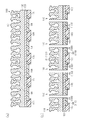
- the conductive metal substrate 20 has a porous portion 21 having a porous structure on one main surface side and a support portion 22 on the other main surface side.
- one main surface is an upper surface
- the other main surface is a lower surface.
- the material constituting the conductive metal substrate 20 is not particularly limited as long as it is a metal, and examples thereof include aluminum, tantalum, nickel, copper, titanium, niobium and iron, and alloys such as stainless steel and duralumin.
- the material constituting the conductive metal substrate 20 is aluminum.
- the porous part 21 has a porous structure with a higher porosity than the support part 22.
- the “porosity” as used herein refers to the area or volume ratio, preferably the area ratio, occupied by the voids in the conductive metal substrate 20.
- the porosity can be measured as follows.
- the conductive metal substrate 20 is processed into a thin piece having a thickness of 60 nm or less by focused ion beam (FIB) processing.
- a predetermined region (3 ⁇ m ⁇ 3 ⁇ m) of the thin sample is photographed using a transmission electron microscope (TEM).
- TEM transmission electron microscope
- Porosity ((measurement area ⁇ area where metal of base material exists) / measurement area) ⁇ 100
- the voids of the porous portion 21 can be finally filled with a non-base material such as a dielectric layer 40 or an electrode layer 50 different from the conductive metal base material 20 in the process of manufacturing the capacitor 10,
- the “porosity” is calculated by considering the filled material without considering the filled material.
- the first lead electrode 30 is provided on the support portion 22 of the conductive metal substrate 20, more specifically, on the main surface 20 c which is the surface of the support portion 22.
- the material which comprises the 1st extraction electrode 30 is not specifically limited, For example, metals and alloys, such as Au, Pb, Ag, Sn, Ni, Cu, a conductive polymer, etc. are mentioned.
- the first extraction electrode 30 is formed by, for example, Cu plating.
- the first lead electrode 30 has a substantially plate shape and has at least one, preferably a plurality of projecting portions 31 projecting from the center thereof in a direction away from the support portion 22 (lower side in FIG. 2).
- the protruding portion 31 is a terminal portion that is electrically connected to the circuit board 1 (see FIG. 1) via the solder connection portion 4.
- the dielectric layer 40 includes a first dielectric layer 41 covering one main surface 20a side of the conductive metal substrate 20, a second dielectric layer 42 covering the side surface 20b side, and one side on the other main surface 20c side. And a third dielectric layer 43 covering the portion.
- the first dielectric layer 41 is configured to cover the porous portion 21 on the entire main surface 20a side.
- the second dielectric layer 42 is configured to extend from the end portion of the first dielectric layer 41 toward the main surface 20c on the opposite side, and is configured to cover the entire side surface 20b.
- the third dielectric layer 43 is configured to extend from the end of the second dielectric layer 42 toward the center and cover a part of the main surface 20a.
- An insulating layer 60 is provided between the third dielectric layer 43 and the first extraction electrode 30.
- the material for forming the dielectric layer 40 is not particularly limited as long as it is insulative, but preferably, AlO x (for example, Al 2 O 3 ), SiO x (for example, SiO 2 ), AlTiO x , SiTiO x , HfO.
- metal oxides such as SiAlO x; AlN x, SiN metal nitrides such as x , AlScN x ; or metal oxynitrides such as AlO x N y , SiO x N y , HfSiO x N y , SiC x O y N z , AlO x , SiO x , SiO x N y and HfSiO x are preferred.
- x, y, and z attached to O and N may be any value larger than 0 (zero), and the abundance ratio of each element including a metal element is arbitrary.
- the dielectric layer 40 is preferably a vapor phase method, such as a vacuum deposition method, a chemical vapor deposition (CVD) method, a sputtering method, an atomic layer deposition (ALD) method, a pulsed laser deposition method (PLD). : Pulsed Laser Deposition) etc.
- the ALD method is more preferable because a layer (film) having a more uniform thickness can be formed in the fine pores of the porous member.
- the electrode layer 50 is formed on the dielectric layer 40. More specifically, a first electrode layer 51 provided on the first dielectric layer 41, a second electrode layer 52 provided on the second dielectric layer 42, and a third electrode provided on the third dielectric layer 43. Layer 53.
- the material constituting the electrode layer 50 is not particularly limited as long as it is conductive, but Ni, Cu, Al, W, Ti, Ag, Au, Pt, Zn, Sn, Pb, Fe, Cr, Mo, Ru, Pd , Ta and alloys thereof such as CuNi, AuNi, AuSn, and metal oxides such as TiN, TiAlN, TiON, TiAlON, TaN, metal oxynitrides, conductive polymers (eg, PEDOT (poly (3,4- Ethylenedioxythiophene)), polypyrrole, polyaniline) and the like, and TiN and TiON are preferred.
- PEDOT poly (3,4- Ethylenedioxythiophene
- polypyrrole polyaniline
- the electrode layer 50 may be formed by an ALD method. By using the ALD method, the capacitance of the capacitor can be increased. Alternatively, the dielectric layer can be coated to substantially fill the pores of the conductive metal substrate, chemical vapor deposition (CVD), plating, bias sputtering, Sol-Gel method, conductive
- the electrode layer 50 may be formed by a method such as filling with a conductive polymer.
- a conductive film is formed on the dielectric layer by the ALD method, and the electrode layer 50 is formed by filling the pores with a conductive material, preferably a material having a lower electrical resistance, by another method. May be. By adopting such a configuration, it is possible to efficiently obtain a higher capacitance density and a lower equivalent series resistance (ESR).
- ESR equivalent series resistance
- the insulating layer 60 is provided between the conductive metal substrate 20 and the electrode layer 50. By providing the insulating layer 60, a short circuit between the electrode layer 50 and the conductive metal substrate 20 is suppressed.
- the material for forming the insulating layer 60 is not particularly limited as long as it is insulating, but a material having heat resistance is preferable when an atomic layer deposition method is used later.
- As an insulating material for forming the insulating layer 60 various glass materials, ceramic materials, polyimide resins, and fluororesins are preferable. In this example, SiO 2 is used as the insulating layer 60.
- the second extraction electrode 70 is formed on the electrode layer 50. More specifically, the second lead electrode 70 is formed on the upper lead electrode portion 71 provided on the first electrode layer 51, the side lead electrode portion 72 provided on the second electrode layer 52, and the third electrode layer 53. And a lower electrode portion 73 provided.
- the material which comprises the 2nd extraction electrode 70 is not specifically limited, For example, metals and alloys, such as Au, Pb, Ag, Sn, Ni, Cu, a conductive polymer, etc. are mentioned. In the present embodiment, the second extraction electrode 70 is formed by, for example, Cu plating.
- a conductive metal substrate 100 is prepared.
- the material constituting the conductive metal substrate 100 include aluminum, tantalum, nickel, copper, titanium, niobium and iron, and alloys such as stainless steel and duralumin.
- the material constituting the conductive metal substrate 100 is aluminum.
- the conductive metal substrate 100 has a porous metal layer 101 on one main surface side and a support layer 102 on the other main surface side. That is, one surface of the conductive metal substrate 100 is constituted by the porous metal layer 101, and the surface of the conductive metal substrate 100 opposite to the one surface is constituted by the support layer 102.
- the conductive layer 103 is previously formed on the support layer 102 of the conductive metal substrate 100 by Cu plating. On the conductive layer 103, a plurality of insulating portions 104 formed by vapor deposition or sputtering and a covering portion 105 formed by coating between the insulating layers 104 are provided.
- the conductive metal substrate 100 and the insulating portion 104 are cut.
- FIG. Each of the cut pieces 110 has the conductive metal base material 20 and the insulating layer 60 in the capacitor 10 by being cut.
- the dielectric layer 40 is formed on each piece 110, and then the electrode layer 50 is formed using the ALD method. At this time, the layers 40 and 50 are also formed on the insulating layer 60 and the covering portion 105.
- a Ti / Cu sputtered film is formed as a pretreatment for electrode formation (not shown). At this time, film formation is performed on the first electrode layer 51 and the second electrode layer 52 of the electrode layer 50. As shown in FIG. 5, the covering portion 105 is removed.
- a method for removing the covering portion 105 is not particularly limited, and examples thereof include a method of removing the covering portion 105 by laser treatment or chemical treatment.
- a Ti / Cu sputtered film is formed as a pretreatment for electrode formation (not shown). At this time, film formation is performed on the third electrode layer 53 of the electrode layer 50. Then, the 1st extraction electrode 30 (projection part 31) and the 2nd extraction electrode 70 are formed by Cu plating process. Thus, the second extraction electrode 70 is formed so as to cover the first electrode layer 51, the second electrode layer 52, and the third electrode layer 53, and the protruding portion 31 of the first extraction electrode 30 is formed.
- the dielectric layer, the electrode layer, and the first terminal electrode are configured to cover one main surface 20a and the side surface 20b and the other main surface 20c is covered with the second terminal electrode, the capacitor Each main surface and side surface are covered with any one of the terminal electrodes. Thereby, mechanical strength can be ensured. And by providing the porous portion on one main surface, a part of the main surface can be made a porous portion without being part of a low porosity as in the conventional configuration, so that the capacitance can be reduced. Can be improved.
- the dielectric layer, the electrode layer, and the first terminal electrode are provided so as to cover a part of the other main surface. For this reason, it becomes the structure which has a 1st terminal electrode and a 2nd terminal electrode in the other main surface. Thereby, either when using the first terminal electrode on one main surface and the second terminal electrode on the other main surface, or when using the first terminal electrode and the second terminal electrode on the other main surface Even so, a usable capacitor can be provided, which can improve convenience.
- the thickness of the dielectric layer 40 can be made uniform.
- the thickness of the electrode layer 50 can be made uniform.
- Atomic layer deposition method Since the ALD method is used to continuously form the dielectric layer 40 and the electrode layer 50, it can contribute to productivity improvement. (Modification)
- the said embodiment can also be implemented in the following aspects which changed this suitably.
- the capacitor 10 includes the third dielectric layer 43 covering a part on the main surface 20 c side, the third electrode layer 53 covering the third dielectric layer 43, and the lower portion covering the third electrode layer 53.
- the structure which has the electrode part 73 it is not restricted to this.
- the dielectric layer 40 includes a first dielectric layer 41 and a second dielectric layer 42.
- the electrode layer 50 includes a first electrode layer 51 and a second electrode layer 52.
- the second lead electrode 70 has an upper lead electrode portion 71 and a side lead electrode portion 72. That is, none of the dielectric layer 40, the electrode layer 50, and the second lead electrode 70 covers the main surface 20c side.
- the protruding portion 31 of the first extraction electrode 30 is configured to have a wider shape as compared with the above embodiment.
- the capacitor 10 is embedded in the circuit board 1. Even in such a configuration, the second extraction electrode 70 of the capacitor 10 covers the entire main surface 20a and the side surface 20b, and the first extraction electrode 30 covers the other main surface 20c. Since the strength is ensured, the occurrence of cracking of the capacitor 10 can be suppressed. Note that the capacitor 10 shown in FIG. 6 is not limited to the embedded arrangement, and a surface-mounted configuration similar to the above embodiment may be adopted.
- the dielectric layer 40 and the electrode layer 50 cover the entire main surface 20a and the entire side surface 20b facing in the direction orthogonal to the main surface 20a
- the second lead electrode 70 includes the entire main surface 20a, The entire side surface 20b facing in the direction orthogonal to the main surface 20a and a part of the other main surface 20c are covered.
- the first lead electrode 30 may have a plurality of protrusions 31 to have a multi-terminal structure.
- the second extraction electrode 70 may similarly have a protruding portion 70a to have a multi-terminal structure.
- the protruding portion 70a of the second extraction electrode 70 is configured to extend from the upper extraction electrode portion 71 to the other main surface 20c side.
- a plurality of through holes 20 d are formed in the conductive metal substrate 20.
- the protrusion part 70a of the 2nd extraction electrode 70 is comprised so that the front-end
- FIG. 9 When the capacitor 10 of the second modification shown in FIGS. 8A and 8B is embedded in the circuit board 1, a configuration as shown in FIG. 9 can be considered. That is, the power supply layer 2 of the circuit board 1 and the protruding portion 31 are electrically connected, and the GND layer 3 of the circuit board 1 and the protruding portion 70a are electrically connected and embedded in the circuit board 1. Yes.
- the capacitor 10 shown in FIGS. 8A and 8B is not limited to the embedded arrangement, and a surface-mounted configuration similar to the above embodiment may be adopted. Further, as in the capacitor 10 of the third modification shown in FIGS. 10A and 10B, a plurality of projecting portions 31 may be provided only on the first extraction electrode 30 to form a multi-terminal structure. That is, the protrusion 70a of the second extraction electrode 70 is omitted. In this case, the lower electrode portion 73 of the second extraction electrode 70 is configured to cover the periphery of the protruding portion 31.
- a low inductance can be achieved by providing a plurality of protrusions 31 to form a multi-terminal structure. Further, by providing a plurality of protrusions 70a or by covering the periphery of the protrusion 31 with the lower electrode part 73, it can be used as a multi-terminal structure, and low inductance can be achieved.
- the capacitor 10 has a substantially rectangular parallelepiped shape, but the shape is not limited to this.
- a circular shape, an elliptical shape or the like may be adopted in a plan view.
- the porous portion 21 of the conductive metal substrate 20 of the embodiment can be produced by etching a metal foil such as an aluminum foil, but the conductive metal substrate 20 is not limited to an etched metal foil.
- a metal particle aggregate also referred to as a porous sintered metal block
- heat treatment can be used as a conductive metal substrate.
- the conductive metal substrate 120 is configured as an aggregate (porous sintered metal block) of metal particles 123.
- the metal particle 123 the metal used for the conductive metal substrate 20 of the embodiment can be used.
- the metal particles 123 of the fourth modified example are nickel particles.
- the average particle diameter of the metal particles 123 is set according to the capacity characteristics of the capacitor 10a and the type of the metal particles 123, and can be selected from a range of 50 to 500 nm, for example.
- a neck 123 a is formed between adjacent metal particles 123.
- the pores 120a are formed by one neck 123a or by communication of a plurality of necks 123a.
- a large number of pores 120a are dispersed almost throughout the aggregate of the metal particles 123, and are preferably distributed substantially uniformly. Therefore, most of the aggregates of the metal particles 123 are preferably high porosity portions or porous portions 121.
- the portion of the aggregate of the metal particles 123 that contacts the inner surface (that is, the bottom surface and / or the side surface) of the cavity 160a can function as a support portion 122 that supports the porous portion from below and / or from the side.
- the support part 122 may be a non-porous part or a low porosity part such as a foil-like sintered metal part that spreads in close contact with the inner surface of the cavity 160a.
- the aggregate of the metal particles 123 may have a foil-like sintered metal portion that contacts or closely contacts the entire inner surface of the cavity 160a.
- This foil-like sintered metal portion is formed by heat-treating the metal particles 123 in the cavities 160a in order to form aggregates of the metal particles 123.
- the neck 123a and / or the pores 120a of the aggregate of the metal particles 123 may face the inner surface of the cavity 160a.
- the first terminal electrode 131 and the second terminal electrode 173 of the capacitor 10a are arranged on the same plane (for example, the lower surface) of the capacitor 10a.
- the silicon substrate 160 has at least one via hole 160b extending from the lower surface of the silicon substrate 160 to the cavity 160a.
- the via hole 160b is filled with a via electrode 132 formed by, for example, metal plating.
- the lower surface (for example, the support portion 122) of the conductive metal substrate 120 is electrically connected to the first terminal electrode 131 of the capacitor 10a by the via electrode 132.
- the aggregate of the metal particles 123 is a laminate of the dielectric layer 140 and the electrode layer 150 except for the lower surface (for example, the support portion 122) of the aggregate of the metal particles 123 that is in contact with the inner surface of the cavity 160a. Covered by the membrane 180.
- the dielectric layer 140 is in direct contact with or in close contact with the metal particles 123.
- the dielectric layer 140 covers the metal particles 123 so that the metal surfaces of the metal particles 123 are completely exposed, that is, the metal surfaces are not exposed.
- the electrode layer 150 covers the dielectric layer 140.
- a dielectric layer 140 is sandwiched between the electrode layer 150 and the metal particles 123.
- the laminated film 180 extends from the conductive metal substrate 120 to the lower surface of the capacitor 10a through the outer surface of the silicon substrate 160.
- the laminated film 180 includes a porous portion coating portion 180a that covers the porous portion 121, a portion 180b that covers the upper surface and side surfaces of the silicon substrate 160, and a portion that covers a portion of the lower surface of the silicon substrate 160. And an electrode seat portion 180c on which the second terminal electrode 173 is formed. These portions 180a, 180b, and 180c are continuous without interruption.
- the dielectric layer 140 is in direct contact with or in close contact with the silicon substrate 160.
- the electrode layer 150 covers the dielectric layer 140. Therefore, the electrode layer 150 is not in contact with the upper surface, the side surface, and the lower surface of the silicon substrate 160.
- the second terminal electrode 173 is provided, for example, directly on the electrode layer 150 in the electrode seat portion 180 c of the laminated film 180 covering the lower surface of the silicon substrate 160.
- the first terminal electrode 131 and the second terminal electrode 173 of the capacitor 10a are connected to the circuit board 1 through, for example, the solder connection portion 4 (FIG. 1).
- step a a silicon substrate 160 having a cavity 160a is prepared.
- step b paste 120x containing metal particles (nickel particles) 123 is applied or filled into cavity 160a.
- the paste 120x can be prepared in a paste form by dispersing the metal particles 123 in a solvent such as ethanol, adding a synthetic resin such as polyvinyl alcohol, and mixing or kneading.
- Step c The silicon substrate 160 and the paste 120x are heat-treated at a predetermined temperature (300 to 400 ° C. in the fourth modification) in a reducing atmosphere in which a mixed gas of nitrogen (N 2 ) and hydrogen (H 2 ) is flowed. .
- a mixed gas of nitrogen (N 2 ) and hydrogen (H 2 ) is flowed.
- the metal particles 123 are sintered, and the conductive metal substrate 120 having the porous portion 121 is formed by forming the neck 123 a between the adjacent metal particles 123.
- the support part 122 is formed by a part of the metal particles 123 being in close contact with or in surface contact with the inner surface of the cavity 160a by the heat treatment.
- the temperature and time of the heat treatment are set so that the capacitor 10a has desired electrical characteristics, for example, the conductive metal substrate 120 (particularly, the porous portion 121) has a desired porosity, and the type of metal of the metal particles 123. And can be set or adjusted according to the average particle size.
- Step d The conductive metal substrate 120 and the silicon substrate 160 are covered with the laminated film 180 (dielectric layer 140 and electrode layer 150).
- This covering includes the step of forming the dielectric layer 140 and the step of forming the electrode layer 150 on the dielectric layer 140 next.
- the dielectric layer 140 and the electrode layer 150 are deposited by an ALD method.
- the dielectric layer 140 and the electrode layer 150 may be formed by the same material and method as the dielectric layer 40 and the electrode layer 50 of the embodiment.
- a via electrode 132 is formed on the silicon substrate 160.
- the laminated film 180 (dielectric layer 140 and electrode layer 150) at the via formation portion is partially removed so that the electrode seat portion 180c of the laminated film 180 remains on the lower surface of the silicon substrate 160, and the lower surface of the silicon substrate 160 is removed.
- a via hole 160b extending from the cavity 160a to the cavity 160a is formed, and a via electrode 132 is formed in the via hole 160b by Cu plating, for example.
- Step f A metal plating film is formed on the conductive surface exposed on the outermost surface by, for example, Cu plating.
- the metal plating film constitutes the first terminal electrode 131 on the via electrode 132 and the second terminal electrode 173 on the electrode layer 150 in the electrode seat portion 180c of the laminated film 180 covering the lower surface of the silicon substrate 160. To do.
- the capacitor 10a of the fourth modified example can be manufactured through such a series of steps. According to the fourth modification, in addition to the actions described in relation to the embodiment and the modification, the following actions are obtained.
- the conductive metal substrate 120 having a desired porosity can be produced by a relatively simple heat treatment. Since the conductive metal substrate 120 can be produced in the cavity 160a of the silicon substrate 160, the ratio of the support 122 in the conductive metal substrate 120 can be minimized, and most of the conductive metal substrate 120 is preferably The whole can be formed as a porous portion 121. Therefore, it is advantageous for increasing the capacity of the conductive metal substrate 120.
- the conductive metal substrate 120 is accommodated in the cavity 160a of the silicon substrate 160 and the side surface of the conductive metal substrate 120 is supported by the silicon substrate 160, the mechanical strength of the capacitor 10a is improved.
- the via electrode 132 is connected to the lower surface of the conductive metal substrate 120. Therefore, the electrode material (for example, copper) can be reduced as compared with the embodiment in which the first extraction electrode 30 is connected to the entire lower surface of the conductive metal substrate 20.
- Capacitor 10b includes a silicon substrate 260 that is a flat substrate having no flat surface and a flat surface 260a, and a conductive metal substrate 220 provided on flat surface 260a of silicon substrate 260.
- This conductive metal substrate 220 is configured as an aggregate of metal particles 123, as in the fourth modification shown in FIG. Most of the aggregates of the metal particles 123 are the high porosity portion or the porous portion 221.
- a portion of the aggregate of the metal particles 123 that contacts the flat surface 260a of the silicon substrate 260 is a support portion 222 that supports the porous portion 221 from below.
- the support part 222 may be a non-porous part or a low porosity part such as a foil-like sintered metal part that spreads in close contact with the flat surface 260 a of the silicon substrate 260.
- the dielectric layer 140, the electrode layer 150, and the via electrode 132 are the same as those in the fourth modified example. Similar to the second lead electrode 70 of the embodiment, the metal plating film 270 is formed around the capacitor 10b, that is, on the upper surface, the side surface, and the lower surface. The metal plating film 270 seals and protects the conductive metal base material 220, the dielectric layer 140, and the electrode layer 150 on the silicon substrate 260. Parts of the metal plating film 270 formed on the lower surface of the silicon substrate 260 function as the first terminal electrode 131 and the second terminal electrode 173 of the capacitor 10b, as in the fourth modification.
- step a a flat silicon substrate 260 is prepared.
- step b a paste 120 x containing metal particles (nickel particles) 123 is applied to the flat surface 260 a of the silicon substrate 260.
- Steps c, d, and e are the same as in the fourth modification.
- Step f A metal plating film 270 is formed on the conductive surface exposed on the outermost surface by, for example, Cu plating.
- the metal plating film 270 forms the metal plating film 270 that covers, seals, and protects the conductive metal substrate 220 and the laminated film 180 without interruption.
- the metal plating film 270 supports the conductive metal substrate 220 from the side.
- the first terminal electrode 131 and the second terminal electrode 173 of the capacitor 10 b are formed by several portions of the metal plating film 270 formed on the lower surface of the silicon substrate 260.
- the metal plating film 270 is formed after the heat treatment (step c) for forming the conductive metal base material (porous sintered metal block) 220.
- the capacitor 10b of the fifth modified example can be manufactured through such a series of steps.
- the following actions are obtained.
- the silicon substrate 260 since the flat silicon substrate 260 is used, the silicon substrate 260 can be obtained or prepared at a lower cost than a silicon substrate having a cavity.
- the porous part 21 of the electroconductive metal base material 20 may be called the upper part of the electroconductive metal base material 20, or a high porosity part.
- the support portion 22 of the conductive metal substrate 20 may be referred to as a lower portion, a non-porous portion, or a low porosity portion of the conductive metal substrate 20.
- Capacitors (10; 10a; 10b) according to some embodiments of the present invention are: A conductive metal substrate (20; 120: 220) having a porous portion (21; 121; 221) and a support portion (22; 122; 222) that supports the porous portion from at least below; The first conductive material provided at a position different from the conductive metal substrate (20; 120: 220) and conducting to the support portion (22; 122; 222) of the conductive metal substrate (20; 120: 220).
- the second conductive material is provided at a position different from the conductive metal substrate (20; 120: 220) and is electrically connected to the porous portion (21; 121; 221) of the conductive metal substrate (20; 120: 220).
- the laminated film (40, 50; 140, 150) A porous portion coating portion (180a) covering the metal surface of the porous portion (21; 121; 221); An electrode seat portion (180c) different from the porous portion coating portion (180a), on which the second terminal electrode (70; 173) is formed,
- the dielectric layer (40; 140) In the porous portion coating portion (180a) of the laminated film (40, 50; 140, 150), the porous portion (21; 121; 221) is provided so that the metal surface of the porous portion (21; 121; 221) is not exposed.
- the dielectric layer (40; 140) includes the second terminal in the electrode seat portion (180c) of the laminated film (40, 50; 140, 150) with the electrode layer (50; 150) interposed therebetween. It faces the electrode (70; 173).
- the porous portion coating portion (180a) and the electrode seat portion (180c) of the laminated film (40, 50; 140, 150) are continuous without interruption.
- the conductive metal substrate (20) includes an upper part having a first predetermined height and a lower part having a second predetermined height (20 And the whole of the upper part has a higher porosity than the whole of the lower part.
- the conductive metal substrate (20) is an etched surface that functions as the porous portion (21), and a non-etched surface opposite to the etched surface, An etched metal foil having the non-etched surface functioning as the support portion (22).
- the conductive metal substrate (120; 220) is a porous sintered metal block (120; 220) that is a sintered body of a plurality of metal particles (123). is there.
- the porous sintered metal block (120; 220) comprises pores (120a) formed by necks (123a) between adjacent metal particles (123). .
- the capacitor (10a; 10b) includes a substrate (160; 260) that supports the porous sintered metal block (120; 220) from below;
- the support portion (122: 222) includes a lower portion of the porous sintered metal block (120; 220) that supports the porous portion (121; 221) at least from below and contacts the substrate (160).
- the substrate (160) has a cavity (160a), and the porous sintered metal block (120) is received in the cavity (160a), and the substrate ( 160) from below and from the side.
- the substrate (260) is a flat substrate (260) having no flat surface and having a flat surface (260a), and the porous sintered metal block (220) includes: Supported by the flat surface (260a) from below, the capacitor (10b) further includes a metal plating layer (270) that covers the substrate (260) and supports the porous sintered metal block (220) from the side. Prepare.
- SYMBOLS 1 Circuit board, 10, 10a, 10b ... Capacitor, 20, 120, 220 ... Conductive metal base material, 20a ... Main surface (one main surface), 20b ... Side surface, 20c ... Main surface (the other main surface) , 20d ... through hole, 21, 121, 221 ... porous portion, 22, 122, 222 ... support portion, 30, 131 ... first extraction electrode (first terminal electrode), 31 ... protrusion (terminal of first extraction electrode) Part), 40, 140 ... dielectric layer, 50, 150 ... electrode layer, 60 ... insulating layer, 70, 173 ... second lead electrode (second terminal electrode).
Abstract
コンデンサ10は、一方の主面20aに多孔部21を有する導電性金属基材20と、一方の主面20a全体並びに該主面20aと直交する方向に面する側面20b全体を覆う誘電体層40と、誘電体層40上を覆う態様で設けられる電極層50と、電極層50上を覆う態様で設けられる第2引き出し電極70と、導電性金属基材20の他方の主面20cを覆う第1引き出し電極30と、電極層50と導電性金属基材20との間を絶縁する絶縁層60と、を備える。
Description
本発明は、コンデンサ及びコンデンサの実装構造に関するものである。
従来、コンデンサとして大きな静電容量を得るべく、多孔構造の導電性金属基材を用いたものが知られている(例えば特許文献1参照)。
特許文献1のコンデンサは、前記導電性金属基材と、導電性金属基材上に形成される誘電体層と、誘電体層上に形成される上部電極と、導電性金属基材に電気的に接続された第1端子電極と、前記上部電極と電気的に接続された第2端子電極とを有する。そして、導電性金属基材は、相対的に空隙率の高い高空隙率部と、高空隙率部の周囲であって高空隙率部よりも空隙率の低い低空隙率部を有する構成となっている。
特許文献1のコンデンサは、前記導電性金属基材と、導電性金属基材上に形成される誘電体層と、誘電体層上に形成される上部電極と、導電性金属基材に電気的に接続された第1端子電極と、前記上部電極と電気的に接続された第2端子電極とを有する。そして、導電性金属基材は、相対的に空隙率の高い高空隙率部と、高空隙率部の周囲であって高空隙率部よりも空隙率の低い低空隙率部を有する構成となっている。
ところで、上記のようなコンデンサにおいては、低空隙率部を有することにより、機械的強度を十分に確保するようになっている。しかしながら、低空隙率部を有することにより、静電容量が十分に確保できない虞がある。
本発明は上記問題点を解決するためになされたものであって、その目的は、機械的強度を確保しつつ静電容量を向上させることが可能なコンデンサ及びコンデンサの実装構造を提供することにある。
上記課題を解決するコンデンサは、一方の主面に多孔部を有する導電性金属基材と、前記一方の主面全体並びに該主面と直交する方向に面する側面全体を覆う誘電体層と、前記誘電体層上を覆う態様で設けられる電極層と、前記導電性金属基材の他方の主面を覆う第1端子電極と、前記電極層上を覆う態様で設けられる第2端子電極と、前記電極層と前記導電性金属基材との間を絶縁する絶縁層と、を備える。
この構成によれば、誘電体層、電極層及び第2端子電極が一方の主面並びに側面を覆うように構成され、他方の主面を第1端子電極で覆うように構成されるため、コンデンサの各主面並びに側面がいずれかの端子電極で覆われた構成となる。これにより、機械的強度を確保することができる。そして、多孔部を一方の主面に設けることで、従来構成のように一部が低空隙率部とならずに、一方の主面全体を多孔部とすることができるため、静電容量を向上させることができる。
上記コンデンサにおいて、前記誘電体層は、前記一方の主面全体並びに該主面と直交する方向に面する前記側面全体に加えて、前記他方の主面の一部を覆う態様で設けられ、前記電極層は、前記誘電体層全体を覆う態様で設けられ、前記第2端子電極は、前記電極層全体を覆う態様で設けられる、ことが好ましい。
この構成によれば、誘電体層、電極層及び第2端子電極が他方の主面の一部を覆う態様で設けられる。このため、他方の主面において第1端子電極と第2端子電極とを有する構成となる。これにより、一方の主面の第2端子電極と他方の主面の第1端子電極とを利用する場合と、他方の主面の第2端子電極及び第1端子電極を利用する場合とのいずれであっても利用可能なコンデンサを提供することができ、利便性の面で向上できる。
上記コンデンサにおいて、前記第1端子電極は、前記導電性金属基材の他方の主面側において複数の端子部を有することが好ましい。
この構成によれば、第1端子電極は、導電性金属基材の他方の主面側において複数の端子部を有するため、低インダクタンスとすることができる。
この構成によれば、第1端子電極は、導電性金属基材の他方の主面側において複数の端子部を有するため、低インダクタンスとすることができる。
上記コンデンサにおいて、前記導電性金属基材は、前記一方の主面から前記他方の主面に貫通する貫通孔を有し、前記第2端子電極は、前記一方の主面側から前記導電性金属基材の前記貫通孔を介して前記他方の主面側に延出する態様で設けられることが好ましい。
この構成によれば、第2端子電極を前記貫通孔を介して他方の主面側まで延出させることができるこれにより、一方の主面の第2端子電極と他方の主面の第1端子電極とを利用する場合と、他方の主面の第2端子電極及び第1端子電極を利用する場合とのいずれであっても利用可能なコンデンサを提供することができ、利便性の面で向上できる。
上記コンデンサにおいて、前記導電性金属基材の前記貫通孔は、複数設けられ、前記第2端子電極は、前記一方の主面側から前記導電性金属基材の各貫通孔を介して前記他方の主面側に延出する態様で設けられることが好ましい。
この構成によれば、第2端子電極を他方の主面において複数の端子部を設ける構成とすることができるため、低インダクタンスとすることができる。
いくつかの特定の態様では、前記導電性金属基材は、前記多孔部と、当該多孔部を少なくとも下から支える支持部とを含むワンピース品である。この構成によれば、導電性金属基材用の母材を切断することによって導電性金属基材を準備することができる。
いくつかの特定の態様では、前記導電性金属基材は、前記多孔部と、当該多孔部を少なくとも下から支える支持部とを含むワンピース品である。この構成によれば、導電性金属基材用の母材を切断することによって導電性金属基材を準備することができる。
いくつかの特定の態様では、前記導電性金属基材は、エッチド金属箔であり、前記導電性金属基材の前記一方の主面はエッチド面であり、前記導電性金属基材の前記他方の主面は、前記エッチド面の反対側の非エッチド面である。この構成によれば、金属箔の片面をエッチングすることによって導電性金属基材を準備するこができる。
いくつかの特定の態様では、前記導電性金属基材は、複数の金属粒子の焼結体である多孔性焼結金属ブロックである。この構成によれば、金属粒子を熱処理することによって導電性金属基材を準備するこができる。
いくつかの特定の態様では、前記多孔性焼結金属ブロックは、隣接する金属粒子間のネックによって形成される細孔を備える。この構成によれば、金属粒子の種類および/または熱処理条件を変更または調整することによって、導電性金属基材の空隙率を制御するこができる。
いくつかの特定の態様では、前記コンデンサは、前記多孔性焼結金属ブロックの下部を下から支える基板を備える。この構成によれば、複数の金属粒子を基板上で熱処理することによって導電性金属基材として機能する多孔性焼結金属ブロックを準備するこができる。
いくつかの特定の態様では、前記基板はキャビティを有し、前記多孔性焼結金属ブロックは、前記キャビティに収容され、前記基板によって下から及び側方から支えられる。この構成によれば、複数の金属粒子を基板のキャビディ内で熱処理することによって導電性金属基材として機能する多孔性焼結金属ブロックを準備するこができる。また、基板によって導電性金属基材を下から及び側方から支えることができる。
いくつかの特定の態様では、前記基板はキャビティがなく平坦面を有する平板状の基板であり、前記多孔性焼結金属ブロックは、前記基板の前記平坦面によって下から支えられ、前記コンデンサは、前記基板を覆うとともに前記多孔性焼結金属ブロックを側方から支える金属めっき層を更に備える。この構成によれば、複数の金属粒子を基板の平坦面上で熱処理することによって導電性金属基材として機能する多孔性焼結金属ブロックを準備するこができる。また、導電性金属基材を基板によって下から支え、金属めっき層によって側方から支えることができる。
上記課題を解決するコンデンサの実装構造は、上記コンデンサを回路基板の表面に設ける。
この構成によれば、上記したいずれかまたは全ての効果を得ることができる。
この構成によれば、上記したいずれかまたは全ての効果を得ることができる。
上記課題を解決するコンデンサの実装構造は、上記いずれかに記載のコンデンサを回路基板に埋め込み配置する。
この構成によれば、上記したいずれかまたは全ての効果を得ることができる。
この構成によれば、上記したいずれかまたは全ての効果を得ることができる。
本発明のコンデンサ及びコンデンサの実装構造によれば、機械的強度を確保しつつ静電容量を向上させることができるという効果を奏する。
以下、各実施形態のコンデンサについて添付図面を参照して説明する。なお、添付図面は、理解を容易にするために構成要素を拡大して示している場合がある。また、構成要素の寸法比率は、実際のものと、または別の図面中のものと異なる場合がある。
図1に示すように、本実施形態のコンデンサ10は、回路基板1の表面に設けられ、回路基板1に備えられる電源層2並びにGND層3と電気的に接続される。その接続方法は例えば、はんだ(例えば図1のはんだ接続部4)で接続される。また、本実施形態では回路基板1上に集積回路5が設けられている。集積回路5は、前記電源層2並びにGND層3と電気的に接続される。即ち、コンデンサ10と集積回路5は同一回路上に接続されている。
図2に示すように、コンデンサ10は、導電性金属基材20と、第1引き出し電極30と、誘電体層40と、電極層50と、絶縁層60と、第2引き出し電極70とを有している。なお本実施形態のコンデンサ10は、略直方体形状となる態様で構成される。なお、「略直方体状」には、角部や稜線部が面取りされた直方体や、角部や稜線部が丸められた直方体が含まれるものとする。
図2に示すように、導電性金属基材20は、一方の主面側に多孔構造の多孔部21を有し、他方の主面側に支持部22を有する。なお、図2において一方の主面は上面であり、他方の主面は下面である。
導電性金属基材20を構成する材料としては、金属であれば特に限定されないが、例えばアルミニウム、タンタル、ニッケル、銅、チタン、ニオブおよび鉄、ならびにステンレス、ジュラルミン等の合金等が挙げられる。好ましくは、導電性金属基材20を構成する材料は、アルミニウムである。
多孔部21は、支持部22よりも空隙率が高い多孔構造を有する。なお、本明細書でいう「空隙率」とは、導電性金属基材20において空隙が占める面積または体積の割合、好ましくは面積の割合を言う。当該空隙率は、下記のようにして測定することができる。
まず、導電性金属基材20を、集束イオンビーム(FIB:Focused Ion Beam)加工で60nm以下の厚みの薄片に加工する。この薄片試料の所定の領域(3μm×3μm)を、透過型電子顕微鏡(TEM:Transmission Electron Microscope)を用いて撮影する。得られた画像を画像解析することにより、導電性金属基材20の金属が存在する面積を求める。そして、下記式から空隙率を求めることができる。
空隙率=((測定面積-基材の金属が存在する面積)/測定面積)×100
なお、上記多孔部21の空隙は、コンデンサ10を作製するプロセスにおいて、最終的に導電性金属基材20とは異なる誘電体層40や電極層50などの非基材物質で充填され得るが、上記「空隙率」は、このように充填された物質は考慮せず、充填された箇所も空隙とみなして算出する。
空隙率=((測定面積-基材の金属が存在する面積)/測定面積)×100
なお、上記多孔部21の空隙は、コンデンサ10を作製するプロセスにおいて、最終的に導電性金属基材20とは異なる誘電体層40や電極層50などの非基材物質で充填され得るが、上記「空隙率」は、このように充填された物質は考慮せず、充填された箇所も空隙とみなして算出する。
第1引き出し電極30は、導電性金属基材20の支持部22上、より詳しくは支持部22の表面である主面20cに設けられる。第1引き出し電極30を構成する材料は特に限定されないが、例えば、Au、Pb、Ag、Sn、Ni、Cu等の金属および合金、ならびに導電性高分子などが挙げられる。本実施形態では、例えばCuめっき処理により第1引き出し電極30を形成している。
第1引き出し電極30は、略板状をなし、その中央から前記支持部22から離間する方向(図2において下側)に向かって突出する少なくとも一つの好ましくは複数の突出部31を有する。突出部31は、回路基板1(図1参照)とはんだ接続部4を介して電気的に接続される端子部である。
誘電体層40は、導電性金属基材20の一方の主面20a側を覆う第1誘電体層41と、側面20b側を覆う第2誘電体層42と、他方の主面20c側の一部を覆う第3誘電体層43とを有する。
第1誘電体層41は、主面20a側全体であって多孔部21を覆うように構成される。第2誘電体層42は、第1誘電体層41の端部から反対側の主面20cに向かって延びるように構成されて側面20bの全体を覆うように構成される。第3誘電体層43は、第2誘電体層42の端部から中央寄りに延出して主面20aの一部を覆うように構成される。なお、第3誘電体層43と第1引き出し電極30との間には絶縁層60が設けられる。
誘電体層40を形成する材料は、絶縁性であれば特に限定されないが、好ましくは、AlOx(例えば、Al2O3)、SiOx(例えば、SiO2)、AlTiOx、SiTiOx、HfOx、TaOx、ZrOx、HfSiOx、ZrSiOx、TiZrOx、TiZrWOx、TiOx、SrTiOx、PbTiOx、BaTiOx、BaSrTiOx、BaCaTiOx、SiAlOx等の金属酸化物;AlNx、SiNx、AlScNx等の金属窒化物;またはAlOxNy、SiOxNy、HfSiOxNy、SiCxOyNz等の金属酸窒化物が挙げられ、AlOx、SiOx、SiOxNy、HfSiOxが好ましい。なお、上記の式は、単に材料の構成を表現するものであり、組成を限定するものではない。即ち、OおよびNに付されたx、yおよびzは0(ゼロ)より大きい任意の値であってもよく、金属元素を含む各元素の存在比率は任意である。
誘電体層40は、好ましくは、気相法、例えば真空蒸着法、化学蒸着(CVD:Chemical Vapor Deposition)法、スパッタ法、原子層堆積(ALD:Atomic Layer Deposition)法、パルスレーザー堆積法(PLD:Pulsed Laser Deposition)等により形成される。多孔部材の細孔の細部にまで厚みがより均一な層(膜)を形成できることから、ALD法がより好ましい。
電極層50は、誘電体層40上に形成されている。より詳しくは第1誘電体層41上に設けられる第1電極層51と、第2誘電体層42上に設けられる第2電極層52と、第3誘電体層43上に設けられる第3電極層53とを有する。
電極層50を構成する材料は、導電性であれば特に限定されないが、Ni、Cu、Al、W、Ti、Ag、Au、Pt、Zn、Sn、Pb、Fe、Cr、Mo、Ru、Pd、Taおよびそれらの合金、例えばCuNi、AuNi、AuSn、ならびにTiN、TiAlN、TiON、TiAlON、TaN等の金属酸化物、金属酸窒化物、導電性高分子(例えば、PEDOT(ポリ(3,4-エチレンジオキシチオフェン))、ポリピロール、ポリアニリン)などが挙げられ、TiN、TiONが好ましい。
電極層50は、ALD法により形成してもよい。ALD法を用いることにより、コンデンサの静電容量をより大きくすることができる。別法として、誘電体層を被覆し、導電性金属基材の細孔を実質的に埋めることのできる、化学蒸着(CVD:Chemical Vapor Deposition)法、めっき、バイアススパッタ、Sol-Gel法、導電性高分子充填などの方法で、電極層50を形成してもよい。好ましくは、誘電体層上にALD法で導電性膜を形成し、その上から他の手法により、導電性物質、好ましくはより電気抵抗の小さな物質で細孔を充填して電極層50を形成してもよい。このような構成とすることにより、効率的により高い静電容量密度および低い等価直列抵抗(ESR:Equivalent Series Resistance)を得ることができる。
絶縁層60は、導電性金属基材20と電極層50との間に設けられる。絶縁層60を設けることで、電極層50と導電性金属基材20との間での短絡(ショート)が抑えられている。絶縁層60を形成する材料は、絶縁性であれば特に限定されないが、後に原子層堆積法を利用する場合、耐熱性を有する材料が好ましい。絶縁層60を形成する絶縁性材料としては、各種ガラス材料、セラミック材料、ポリイミド樹脂、フッ素樹脂が好ましい。本例では絶縁層60としてSiO2を用いている。
第2引き出し電極70は、電極層50上に形成されている。より詳しくは、第2引き出し電極70は、第1電極層51上に設けられる上部引き出し電極部71と、第2電極層52上に設けられる側面引き出し電極部72と、第3電極層53上に設けられる下部電極部73とを有する。第2引き出し電極70を構成する材料は特に限定されないが、例えば、Au、Pb、Ag、Sn、Ni、Cu等の金属および合金、ならびに導電性高分子などが挙げられる。本実施形態では、例えばCuめっき処理により第2引き出し電極70を形成している。
次に、上記のようの構成されたコンデンサ10の製造工程(製造方法)について説明する。
図3(a)に示すように、先ず、導電性金属基板100を準備する。導電性金属基板100を構成する材料としては、例えばアルミニウム、タンタル、ニッケル、銅、チタン、ニオブおよび鉄、ならびにステンレス、ジュラルミン等の合金等が挙げられる。好ましくは、導電性金属基板100を構成する材料は、アルミニウムである。導電性金属基板100は、一方の主面側に多孔質金属層101を有し、他の主面側に支持層102を有する。つまり、導電性金属基板100の一面は多孔質金属層101で構成され、導電性金属基板100の前記一面とは反対側の面は、支持層102で構成されている。
図3(a)に示すように、先ず、導電性金属基板100を準備する。導電性金属基板100を構成する材料としては、例えばアルミニウム、タンタル、ニッケル、銅、チタン、ニオブおよび鉄、ならびにステンレス、ジュラルミン等の合金等が挙げられる。好ましくは、導電性金属基板100を構成する材料は、アルミニウムである。導電性金属基板100は、一方の主面側に多孔質金属層101を有し、他の主面側に支持層102を有する。つまり、導電性金属基板100の一面は多孔質金属層101で構成され、導電性金属基板100の前記一面とは反対側の面は、支持層102で構成されている。
導電性金属基板100の支持層102には、予めCuめっき処理により、導電層103が形成されている。導電層103上には、蒸着又はスパッタにより形成される複数の絶縁部104と、各絶縁層104間において塗布により形成される被覆部105とを有する。
図3(b)に示すように、導電性金属基板100並びに絶縁部104を切断する。本実施形態では、被覆部105間で複数の個片部110となるように切断する。切断された各個片部110は、切断されることでコンデンサ10における導電性金属基材20と、絶縁層60とを有することとなる。
図4に示すように、各個片部110に対して誘電体層40を形成し、その後に電極層50をそれぞれALD法を用いて形成する。このとき、絶縁層60並びに被覆部105にも各層40,50が成膜されるようになっている。
次いで、電極形成の前処理として例えばTi/Cuスパッタ膜を形成する(図示略)。このとき、電極層50の第1電極層51及び第2電極層52に対して成膜を行う。
図5に示すように、被覆部105を除去する。被覆部105の除去方法は特に問わないが、例えばレーザ処理、化学処理により除去する方法が挙げられる。
図5に示すように、被覆部105を除去する。被覆部105の除去方法は特に問わないが、例えばレーザ処理、化学処理により除去する方法が挙げられる。
次いで、電極形成の前処理として例えばTi/Cuスパッタ膜を形成する(図示略)。このとき、電極層50の第3電極層53に対して成膜を行う。
その後、Cuめっき処理により第1引き出し電極30(突出部31)及び第2引き出し電極70を形成する。これにより、第1電極層51、第2電極層52及び第3電極層53を覆うように第2引き出し電極70が形成され、第1引き出し電極30の突出部31が形成される。
その後、Cuめっき処理により第1引き出し電極30(突出部31)及び第2引き出し電極70を形成する。これにより、第1電極層51、第2電極層52及び第3電極層53を覆うように第2引き出し電極70が形成され、第1引き出し電極30の突出部31が形成される。
以上説明した本実施形態によれば、以下の作用効果を奏することができる。
(1)誘電体層、電極層及び第1端子電極が一方の主面20a並びに側面20bを覆うように構成され、他方の主面20cを第2端子電極で覆うように構成されるため、コンデンサの各主面並びに側面がいずれかの端子電極で覆われた構成となる。これにより、機械的強度を確保することができる。そして、多孔部を一方の主面に設けることで、従来構成のように一部が低空隙率部とならずに、一方の主面全体を多孔部とすることができるため、静電容量を向上させることができる。
(1)誘電体層、電極層及び第1端子電極が一方の主面20a並びに側面20bを覆うように構成され、他方の主面20cを第2端子電極で覆うように構成されるため、コンデンサの各主面並びに側面がいずれかの端子電極で覆われた構成となる。これにより、機械的強度を確保することができる。そして、多孔部を一方の主面に設けることで、従来構成のように一部が低空隙率部とならずに、一方の主面全体を多孔部とすることができるため、静電容量を向上させることができる。
(2)誘電体層、電極層及び第1端子電極が他方の主面の一部を覆う態様で設けられる。このため、他方の主面において第1端子電極と第2端子電極とを有する構成となる。これにより、一方の主面の第1端子電極と他方の主面の第2端子電極とを利用する場合と、他方の主面の第1端子電極及び第2端子電極を利用する場合とのいずれであっても利用可能なコンデンサを提供することができ、利便性の面で向上できる。
(3)誘電体層40を原子層堆積法(ALD法)により形成することで、誘電体層40の厚みを均一とすることができる。
(4)電極層50を原子層堆積法(ALD法)により形成することで、電極層50の厚みを均一とすることができる。
(4)電極層50を原子層堆積法(ALD法)により形成することで、電極層50の厚みを均一とすることができる。
(5)原子層堆積法ALD法を用いて誘電体層40と、電極層50とを連続的に形成する構成であるため、生産性向上に寄与できる。
(変形例)
なお、上記実施形態は、これを適宜変更した以下の態様にて実施することもできる。
(変形例)
なお、上記実施形態は、これを適宜変更した以下の態様にて実施することもできる。
・上記実施形態では、コンデンサ10は、主面20c側の一部を覆う第3誘電体層43と、第3誘電体層43を覆う第3電極層53と、第3電極層53を覆う下部電極部73とを有する構成としたが、これに限らない。
図6及び図7に示すように、第1変形例のコンデンサ10では、誘電体層40は、第1誘電体層41及び第2誘電体層42を有する。電極層50は、第1電極層51及び第2電極層52を有する。第2引き出し電極70は、上部引き出し電極部71及び側面引き出し電極部72を有する。即ち、誘電体層40、電極層50及び第2引き出し電極70のいずれも主面20c側を覆わない構成となっている。また、図6及び図7においては、第1引き出し電極30の突出部31が上記実施形態と比較して幅広形状をなすように構成されている。
なお、図7に示す構成では、回路基板1内にコンデンサ10を埋め込み配置した構成となっている。このような構成であっても、コンデンサ10の第2引き出し電極70が一方の主面20a及び側面20b全体を覆い、第1引き出し電極30が他方の主面20cを覆う構成であるため、十分な強度が確保されるため、コンデンサ10の割れ等の発生を抑えることができる。なお、図6に示すコンデンサ10は、埋め込み配置に限らず、上記実施形態と同様に表面実装した構成を採用してもよい。
また、下部電極部73を有し、第3誘電体層43並びに第3電極層53を省略した構成を採用してもよい。つまり、誘電体層40及び電極層50は一方の主面20a全体並びに該主面20aと直交する方向に面する側面20b全体を覆い、第2引き出し電極70は、一方の主面20a全体、該主面20aと直交する方向に面する側面20b全体、及び他方の主面20cの一部を覆う構成となる。
・図8(a)(b)に示す第2変形例のコンデンサ10のように、第1引き出し電極30に複数の突出部31を有して多端子構造としてもよい。これに代えてまたは加えて、第2引き出し電極70についても同様に突出部70aを有して多端子構造としてもよい。第2引き出し電極70の突出部70aは、上部引き出し電極部71から他方の主面20c側に延出するように構成される。ここで、導電性金属基材20には複数の貫通孔20dが形成されている。そして、第2引き出し電極70の突出部70aは、貫通孔20d内に配置された状態で突出部70aの先端70bが貫通孔20dから露出するように構成される。突出部70aの先端70bは、突出部31と面一となる構成が好ましい。
なお、図8(a)(b)に示す第2変形例のコンデンサ10を回路基板1内に埋め込み配置した場合には、図9に示すような構成が考えられる。すなわち、回路基板1の電源層2と突出部31とを電気的に接続し、回路基板1のGND層3と突出部70aとを電気的に接続した状態で回路基板1内に埋め込み配置している。
なお、図8(a)(b)に示すコンデンサ10は埋め込み配置に限らず、上記実施形態と同様に表面実装した構成を採用してもよい。
また、図10(a)(b)に示す第3変形例のコンデンサ10のように、第1引き出し電極30のみに複数の突出部31を設けて多端子構造としてもよい。すなわち、第2引き出し電極70の突出部70aを省略した構成である。この場合、第2引き出し電極70の下部電極部73が突出部31の周囲を覆うような構成となっている。
また、図10(a)(b)に示す第3変形例のコンデンサ10のように、第1引き出し電極30のみに複数の突出部31を設けて多端子構造としてもよい。すなわち、第2引き出し電極70の突出部70aを省略した構成である。この場合、第2引き出し電極70の下部電極部73が突出部31の周囲を覆うような構成となっている。
上述したように突出部31を複数設けて多端子構造とすることで、低インダクタンスとすることができる。また、突出部70aを複数設けたり、下部電極部73によって突出部31の周囲を覆う構成とすることで多端子構造として利用することができ、低インダクタンスとすることができる。
・上記実施形態では、コンデンサ10を略直方体形状としたが、その形状はこれに限定されない。コンデンサの形状として平面視において円状、楕円状などの形状を採用してもよい。
・実施形態の導電性金属基材20の多孔部21は、例えばアルミニウム箔のような金属箔をエッチングすることによって作製することができる、しかし、導電性金属基材20はエッチド金属箔に限定されない。例えば図11~図15を参照して説明するように、熱処理によって作製される金属粒子凝集体(多孔性焼結金属ブロックともいう)を導電性金属基材として使用することができる。
図11に示す第4変形例のコンデンサ10aは、キャビティ160aを有する基板であるシリコン基板160と、シリコン基板160のキャビティ160a内に収容される導電性金属基材120とを備える。図12に示すように、導電性金属基材120は金属粒子123の凝集体(多孔性焼結金属ブロック)として構成される。金属粒子123としては、実施形態の導電性金属基材20に使用される金属を使用することができる。第4変形例の金属粒子123はニッケル粒子である。金属粒子123の平均粒径は、コンデンサ10aの容量特性及び金属粒子123の種類に応じて設定され、例えば、50~500nmの範囲から選択することができる。隣接する金属粒子123の間にネック123aが形成される。一つのネック123aによってまたは複数のネック123aの連通によって細孔120aが形成される。金属粒子123の凝集体のほぼ全体に多数の細孔120aが分散しており、好ましくはほぼ均一に分布している。したがって、金属粒子123の凝集体の大部分好ましくは全体が高空隙率部または多孔部121である。
金属粒子123の凝集体のうちキャビティ160aの内面(すなわち底面および/または側面)に接触する部分は、多孔部を下からおよび/または側方から支持する支持部122として機能することができる。支持部122は、キャビティ160aの内面に密着して広がる箔状焼結金属部分のような非多孔部または低空隙率部であり得る。
金属粒子123の凝集体は、キャビティ160aの内面全体と接触または密着する箔状焼結金属部分を有してもよい。この箔状焼結金属部分は、金属粒子123の凝集体を形成するために金属粒子123をキャビティ160a内で熱処理することによって形成される。金属粒子123の凝集体のネック123aおよび/または細孔120aがキャビティ160aの内面に面してもよい。
次に、導電性金属基材120と、コンデンサ10aの第1端子電極131及び第2端子電極173との導通について説明する。
コンデンサ10aの第1端子電極131及び第2端子電極173は、コンデンサ10aの同じ平面(例えば下面)に配置されている。シリコン基板160は、シリコン基板160の下面からキャビティ160aまで延在する少なくとも一つのビアホール160bを有する。ビアホール160bには、例えば金属めっきによって形成されるビア電極132が充填される。導電性金属基材120の下面(例えば支持部122)はビア電極132によってコンデンサ10aの第1端子電極131に導電的に接続される。
コンデンサ10aの第1端子電極131及び第2端子電極173は、コンデンサ10aの同じ平面(例えば下面)に配置されている。シリコン基板160は、シリコン基板160の下面からキャビティ160aまで延在する少なくとも一つのビアホール160bを有する。ビアホール160bには、例えば金属めっきによって形成されるビア電極132が充填される。導電性金属基材120の下面(例えば支持部122)はビア電極132によってコンデンサ10aの第1端子電極131に導電的に接続される。
図12に示すように、金属粒子123の凝集体は、キャビティ160aの内面と接触する金属粒子123の凝集体の下面(例えば支持部122)を除き、誘電体層140と電極層150との積層膜180によって覆われる。誘電体層140は金属粒子123に直接接触または密着している。誘電体層140は、金属粒子123の金属面を完全にすなわち金属面が露出しないように金属粒子123を被覆する。電極層150は誘電体層140を被覆する。電極層150と金属粒子123との間に誘電体層140が挟まれる。
図11に示すように、積層膜180(誘電体層140及び電極層150)は、導電性金属基材120からシリコン基板160の外面を介してコンデンサ10aの下面まで延在している。積層膜180は、多孔部121を被覆する多孔部コーティング部分180aと、シリコン基板160の上面及び側面を被覆する部分180bと、シリコン基板160の下面の一部を被覆する部分であって、そこに第2端子電極173が形成される電極座部分180cとを含む。これらの部分180a、180b、180cは途切れなく連続している。
誘電体層140はシリコン基板160に直接接触または密着している。電極層150はこの誘電体層140を被覆する。したがって、電極層150は、シリコン基板160の上面、側面及び下面とは非接触である。第2端子電極173は、シリコン基板160の下面を被覆している積層膜180の電極座部分180cにおいて電極層150上に例えば直接に設けられる。コンデンサ10aの第1端子電極131及び第2端子電極173は、例えばはんだ接続部4(図1)を介して回路基板1に接続される。
図13を参照して第4変形例のコンデンサ10aの製造方法を説明する。
工程aにおいて、キャビティ160aが形成されたシリコン基板160を準備する。
工程bにおいて、金属粒子(ニッケル粒子)123を含んだペースト120xをキャビティ160a内に塗布または充填する。このペースト120xは、金属粒子123を、エタノールなどの溶剤に分散し、ポリビニルアルコールなどの合成樹脂を添加し、混合または混練することによってペースト状に調製することができる。
工程aにおいて、キャビティ160aが形成されたシリコン基板160を準備する。
工程bにおいて、金属粒子(ニッケル粒子)123を含んだペースト120xをキャビティ160a内に塗布または充填する。このペースト120xは、金属粒子123を、エタノールなどの溶剤に分散し、ポリビニルアルコールなどの合成樹脂を添加し、混合または混練することによってペースト状に調製することができる。
工程c:窒素(N2)及び水素(H2)の混合ガスを流動させた還元雰囲気中で、シリコン基板160及びペースト120xを所定の温度(第4変形例では300~400℃)で熱処理する。この熱処理によって、金属粒子123が焼結し、隣接する金属粒子123の間にネック123aが形成されて多孔部121を有する導電性金属基材120が作成される。また、熱処理によって一部の金属粒子123がキャビティ160aの内面に密着または面接触して支持部122が形成される。熱処理の温度及び時間は、コンデンサ10aが所望の電気的特性を有するように、例えば導電性金属基材120(特に多孔部121)が所望の空隙率を有するように、金属粒子123の金属の種類及び平均粒径に応じて設定または調整することができる。
工程d:導電性金属基材120及びシリコン基板160を積層膜180(誘電体層140及び電極層150)によって被覆する。この被覆は、誘電体層140を形成する工程と、次に、電極層150を誘電体層140に形成する工程とを含む。好ましくは、誘電体層140及び電極層150はALD法よって堆積される。誘電体層140及び電極層150は、実施形態の誘電体層40及び電極層50と同様の材料及び方法によって形成してもよい。
工程e:シリコン基板160にビア電極132を形成する。例えば、シリコン基板160の下面に積層膜180の電極座部分180cが残るように、ビア形成箇所の積層膜180(誘電体層140及び電極層150)を部分的に除去し、シリコン基板160の下面からキャビティ160aまで延在するビアホール160bを形成し、例えばCuめっき処理によってビアホール160bにビア電極132を形成する。
工程f:最外面に露出している導電性表面に、例えばCuめっき処理によって金属めっき膜を形成する。この金属めっき膜は、ビア電極132上の第1端子電極131、及び、シリコン基板160の下面を被覆している積層膜180の電極座部分180cにおいて電極層150上の第2端子電極173を構成する。
このような一連の工程によって第4変形例のコンデンサ10aを製造することができる。
第4変形例によれば、実施形態及び変形例に関連して説明した作用に加え、以下の作用が得られる。
第4変形例によれば、実施形態及び変形例に関連して説明した作用に加え、以下の作用が得られる。
所望の空隙率を有する導電性金属基材120を比較的簡単な熱処理によって作製することができる。
シリコン基板160のキャビティ160a内で導電性金属基材120を作製できるので、導電性金属基材120における支持部122の比率を最小化することができ、導電性金属基材120の大部分好ましくは全体を多孔部121として形成することができる。したがって、導電性金属基材120の高容量化に有利である。
シリコン基板160のキャビティ160a内で導電性金属基材120を作製できるので、導電性金属基材120における支持部122の比率を最小化することができ、導電性金属基材120の大部分好ましくは全体を多孔部121として形成することができる。したがって、導電性金属基材120の高容量化に有利である。
導電性金属基材120がシリコン基板160のキャビティ160aに収容されており、導電性金属基材120の側面がシリコン基板160によって支えられるので、コンデンサ10aの機械的強度が向上する。
第4変形例では、導電性金属基材120の下面の局所にビア電極132が接続される。したがって、第1引き出し電極30が導電性金属基材20の下面全体に接続される実施形態に比べて、電極材料(例えば銅)を減らすことができる。
図14及び図15を参照して、第5変形例のコンデンサ10bについて説明する。
コンデンサ10bは、キャビティがなく平坦面260aを有する平板状の基板であるシリコン基板260と、シリコン基板260の平坦面260aに設けられる導電性金属基材220とを備える。この導電性金属基材220は、図12に示す第4変形例と同様に、金属粒子123の凝集体として構成される。金属粒子123の凝集体の大部分が高空隙率部または多孔部221である。金属粒子123の凝集体のうちシリコン基板260の平坦面260aに接触する部分は、多孔部221を下から支持する支持部222である。支持部222は、シリコン基板260の平坦面260aに密着して広がる箔状焼結金属部分のような非多孔部または低空隙率部であり得る。
コンデンサ10bは、キャビティがなく平坦面260aを有する平板状の基板であるシリコン基板260と、シリコン基板260の平坦面260aに設けられる導電性金属基材220とを備える。この導電性金属基材220は、図12に示す第4変形例と同様に、金属粒子123の凝集体として構成される。金属粒子123の凝集体の大部分が高空隙率部または多孔部221である。金属粒子123の凝集体のうちシリコン基板260の平坦面260aに接触する部分は、多孔部221を下から支持する支持部222である。支持部222は、シリコン基板260の平坦面260aに密着して広がる箔状焼結金属部分のような非多孔部または低空隙率部であり得る。
誘電体層140、電極層150及びビア電極132については第4変更例のものと同じである。
金属めっき膜270が、実施形態の第2引き出し電極70と同様に、コンデンサ10bの周囲に、すなわち、上面、側面、及び下面に形成されている。金属めっき膜270は、シリコン基板260上の、導電性金属基材220、誘電体層140及び電極層150を封止し保護する。金属めっき膜270のうちシリコン基板260の下面に形成される部分は、第4変形例と同様にコンデンサ10bの第1端子電極131及び第2端子電極173として機能する。
金属めっき膜270が、実施形態の第2引き出し電極70と同様に、コンデンサ10bの周囲に、すなわち、上面、側面、及び下面に形成されている。金属めっき膜270は、シリコン基板260上の、導電性金属基材220、誘電体層140及び電極層150を封止し保護する。金属めっき膜270のうちシリコン基板260の下面に形成される部分は、第4変形例と同様にコンデンサ10bの第1端子電極131及び第2端子電極173として機能する。
図15を参照して第5変形例のコンデンサ10bの製造方法について図13の第4変形例との相違点を説明する。
工程aにおいて、平板状のシリコン基板260を準備する。
工程aにおいて、平板状のシリコン基板260を準備する。
工程bにおいて、金属粒子(ニッケル粒子)123を含んだペースト120xをシリコン基板260の平坦面260aに塗布する。
工程c、d、eは、第4変形例と同じである。
工程c、d、eは、第4変形例と同じである。
工程f:最外面に露出している導電性表面に、例えばCuめっき処理によって金属めっき膜270を形成する。この金属めっき膜270は、導電性金属基材220及び積層膜180を途切れなく覆い、封止し、保護する金属めっき膜270を形成する。この金属めっき膜270は導電性金属基材220を側方から支える。コンデンサ10bの第1端子電極131及び第2端子電極173は、シリコン基板260の下面に形成される金属めっき膜270のいくつかの部分によって形成される。
なお、金属めっき膜270は、導電性金属基材(多孔性焼結金属ブロック)220を形成するための熱処理(工程c)の後に形成される。
このような一連の工程によって第5変形例のコンデンサ10bを製造することができる。
このような一連の工程によって第5変形例のコンデンサ10bを製造することができる。
第5変形例によれば、実施形態及び変形例に関連して説明した作用に加え、以下の作用が得られる。
第5変形例では、平板状のシリコン基板260を使用するので、キャビティを有するシリコン基板よりも安価にシリコン基板260を入手または準備することができる。
第5変形例では、平板状のシリコン基板260を使用するので、キャビティを有するシリコン基板よりも安価にシリコン基板260を入手または準備することができる。
・上記実施形態並びに上記各変形例は適宜組み合わせてもよい。
・上記実施形態において、導電性金属基材20の多孔部21は導電性金属基材20の上部または高空隙率部と呼称することがある。導電性金属基材20の支持部22は導電性金属基材20の下部または非多孔部または低空隙率部と呼称することがある。
・上記実施形態において、導電性金属基材20の多孔部21は導電性金属基材20の上部または高空隙率部と呼称することがある。導電性金属基材20の支持部22は導電性金属基材20の下部または非多孔部または低空隙率部と呼称することがある。
本開示は以下の構成を包含する。限定のためでなく理解の補助として実施形態の構成要素の参照符号を付した。
[付記1]本発明のいくつかの態様に従うコンデンサ(10;10a;10b)は、
多孔部(21;121;221)と、当該多孔部を少なくとも下から支持する支持部(22;122;222)とを有する導電性金属基材(20;120:220)と、
前記導電性金属基材(20;120:220)とは異なる位置に設けられ、前記導電性金属基材(20;120:220)の前記支持部(22;122;222)に導通する第1端子電極(30;131)と、
前記導電性金属基材(20;120:220)とは異なる位置に設けられ、前記導電性金属基材(20;120:220)の前記多孔部(21;121;221)に導通する第2端子電極(70;173)と、
少なくとも前記多孔部(21;121;221)を覆う積層膜(40、50;140、150)であって、誘電体層(40;140)と、前記誘電体層(40;140)の全体を覆う電極層(50;150)とを含む、前記積層膜(40、50;140、150)と
を備え、
前記積層膜(40、50;140、150)は、
前記多孔部(21;121;221)の前記金属面を覆う多孔部コーティング部分(180a)と、
前記多孔部コーティング部分(180a)とは異なる電極座部分(180c)であって、その上に前記第2端子電極(70;173)が形成される電極座部分(180c)とを含み、
前記誘電体層(40;140)は、
前記積層膜(40、50;140、150)の前記多孔部コーティング部分(180a)において、前記多孔部(21;121;221)の金属面が露出しないように前記多孔部(21;121;221)の前記金属面と密着しており、
前記誘電体層(40;140)は、前記積層膜(40、50;140、150)の前記電極座部分(180c)において、前記電極層(50;150)を間に挟んで前記第2端子電極(70;173)と対面している。
[付記2]いくつかの特定の態様では、前記積層膜(40、50;140、150)の前記多孔部コーティング部分(180a)及び前記電極座部分(180c)は途切れなく連続している。
[付記3]いくつかの特定の態様では、前記導電性金属基材(20)は、第1の所定高さを有する上部と、第2の所定高さを有する下部とを含むワンピース品(20)であり、前記上部の全体が前記下部の全体よりも高い空隙率を有する。
[付記4]いくつかの特定の態様では、前記導電性金属基材(20)は、前記多孔部(21)として機能するエッチド面と、前記エッチド面の反対側の非エッチド面であって、前記支持部(22)として機能する前記非エッチド面とを有するエッチド金属箔である。
[付記5]いくつかの特定の態様では、前記導電性金属基材(120;220)は、複数の金属粒子(123)の焼結体である多孔性焼結金属ブロック(120;220)である。
[付記6]いくつかの特定の態様では、前記多孔性焼結金属ブロック(120;220)は、隣接する金属粒子(123)間のネック(123a)によって形成される細孔(120a)を備える。
[付記7]いくつかの特定の態様では、前記コンデンサ(10a;10b)は、前記多孔性焼結金属ブロック(120;220)を下から支える基板(160;260)を備え、
前記支持部(122:222)は、前記多孔部(121;221)を少なくとも下から支えるとともに前記基板(160)に接触する、前記多孔性焼結金属ブロック(120;220)の下部を含む。
[付記8]いくつかの特定の態様では、前記基板(160)はキャビティ(160a)を有し、前記多孔性焼結金属ブロック(120)は、前記キャビティ(160a)に収容され、前記基板(160)によって下から及び側方から支えられる。
[付記9]いくつかの特定の態様では、前記基板(260)はキャビティがなく平坦面(260a)を有する平板状の基板(260)であり、前記多孔性焼結金属ブロック(220)は、前記平坦面(260a)によって下から支えられ、前記コンデンサ(10b)は、前記基板(260)を覆うとともに前記多孔性焼結金属ブロック(220)を側方から支える金属めっき層(270)を更に備える。
1…回路基板、10、10a、10b…コンデンサ、20、120、220…導電性金属基材、20a…主面(一方の主面)、20b…側面、20c…主面(他方の主面)、20d…貫通孔、21、121、221…多孔部、22、122、222…支持部、30、131…第1引き出し電極(第1端子電極)、31…突出部(第1引き出し電極の端子部)、40、140…誘電体層、50、150…電極層、60…絶縁層、70、173…第2引き出し電極(第2端子電極)。
Claims (14)
- 一方の主面に多孔部を有する導電性金属基材と、
前記一方の主面全体並びに該主面と直交する方向に面する側面全体を覆う誘電体層と、
前記誘電体層上を覆う態様で設けられる電極層と、
前記導電性金属基材の他方の主面を覆う第1端子電極と、
前記電極層上を覆う態様で設けられる第2端子電極と、
前記電極層と前記導電性金属基材との間を絶縁する絶縁層と、
を備えたコンデンサ。 - 前記誘電体層は、前記一方の主面全体並びに該主面と直交する方向に面する前記側面全体に加えて、前記他方の主面の一部を覆う態様で設けられ、
前記電極層は、前記誘電体層全体を覆う態様で設けられ、
前記第2端子電極は、前記電極層全体を覆う態様で設けられる、請求項1に記載のコンデンサ。 - 前記第1端子電極は、前記導電性金属基材の他方の主面側において複数の端子部を有する、請求項1又は2に記載のコンデンサ。
- 前記導電性金属基材は、前記一方の主面から前記他方の主面に貫通する貫通孔を有し、
前記第2端子電極は、前記一方の主面側から前記導電性金属基材の前記貫通孔を介して前記他方の主面側に延出する態様で設けられる、請求項1~3のいずれか一項に記載のコンデンサ。 - 前記導電性金属基材の前記貫通孔は、複数設けられ、
前記第2端子電極は、前記一方の主面側から前記導電性金属基材の各貫通孔を介して前記他方の主面側に延出する態様で設けられる、請求項4に記載のコンデンサ。 - 前記導電性金属基材は、前記多孔部と、当該多孔部を少なくとも下から支える支持部とを含むワンピース品である、請求項1~5のいずれか一項に記載のコンデンサ。
- 前記導電性金属基材は、エッチド金属箔であり、
前記導電性金属基材の前記一方の主面はエッチド面であり、
前記導電性金属基材の前記他方の主面は、前記エッチド面の反対側の非エッチド面である、請求項1~6のいずれか一項に記載のコンデンサ。 - 前記導電性金属基材は、複数の金属粒子の焼結体である多孔性焼結金属ブロックである、請求項1~5のいずれか一項に記載のコンデンサ。
- 前記多孔性焼結金属ブロックは、隣接する金属粒子間のネックによって形成される細孔を備える、請求項8に記載のコンデンサ。
- 前記コンデンサは、前記多孔性焼結金属ブロックの下部を下から支える基板を備える、請求項8または9に記載のコンデンサ。
- 前記基板はキャビティを有し、前記多孔性焼結金属ブロックは、前記キャビティに収容され、前記基板によって下から及び側方から支えられる、請求項10に記載のコンデンサ。
- 前記基板はキャビティがなく平坦面を有する平板状の基板であり、前記多孔性焼結金属ブロックは、前記基板の前記平坦面によって下から支えられ、前記コンデンサは、前記基板を覆うとともに前記多孔性焼結金属ブロックを側方から支える金属めっき層を更に備える、請求項10に記載のコンデンサ。
- 請求項1~12のいずれか一項に記載のコンデンサは、回路基板の表面に設けられる、コンデンサの実装構造。
- 請求項1~12のいずれか一項に記載のコンデンサは、回路基板に埋め込み配置される、コンデンサの実装構造。
Priority Applications (2)
| Application Number | Priority Date | Filing Date | Title |
|---|---|---|---|
| JP2018551616A JPWO2018092722A1 (ja) | 2016-11-16 | 2017-11-13 | コンデンサ及びコンデンサの実装構造 |
| US16/411,370 US10535473B2 (en) | 2016-11-16 | 2019-05-14 | Capacitor and capacitor mounting configuration |
Applications Claiming Priority (2)
| Application Number | Priority Date | Filing Date | Title |
|---|---|---|---|
| JP2016-223415 | 2016-11-16 | ||
| JP2016223415 | 2016-11-16 |
Related Child Applications (1)
| Application Number | Title | Priority Date | Filing Date |
|---|---|---|---|
| US16/411,370 Continuation US10535473B2 (en) | 2016-11-16 | 2019-05-14 | Capacitor and capacitor mounting configuration |
Publications (1)
| Publication Number | Publication Date |
|---|---|
| WO2018092722A1 true WO2018092722A1 (ja) | 2018-05-24 |
Family
ID=62146427
Family Applications (1)
| Application Number | Title | Priority Date | Filing Date |
|---|---|---|---|
| PCT/JP2017/040775 WO2018092722A1 (ja) | 2016-11-16 | 2017-11-13 | コンデンサ及びコンデンサの実装構造 |
Country Status (3)
| Country | Link |
|---|---|
| US (1) | US10535473B2 (ja) |
| JP (1) | JPWO2018092722A1 (ja) |
| WO (1) | WO2018092722A1 (ja) |
Cited By (4)
| Publication number | Priority date | Publication date | Assignee | Title |
|---|---|---|---|---|
| JPWO2021193616A1 (ja) * | 2020-03-24 | 2021-09-30 | ||
| KR20220116328A (ko) | 2020-06-29 | 2022-08-22 | 티디케이가부시기가이샤 | 박막 캐패시터 및 이것을 구비하는 전자 회로 기판 |
| WO2023145111A1 (ja) * | 2022-01-31 | 2023-08-03 | 株式会社村田製作所 | コンデンサ |
| WO2023145110A1 (ja) * | 2022-01-31 | 2023-08-03 | 株式会社村田製作所 | コンデンサ |
Families Citing this family (2)
| Publication number | Priority date | Publication date | Assignee | Title |
|---|---|---|---|---|
| MX2022009752A (es) * | 2020-02-06 | 2023-01-11 | Saras Micro Devices Inc | Condensadores planos de aluminio de alta densidad para apilamiento e incorporacion. |
| CN114751743B (zh) * | 2022-04-29 | 2023-03-07 | 电子科技大学 | 一种多层陶瓷电容器用改性Ni-Ti-Ta介质材料及其低温制备方法 |
Citations (6)
| Publication number | Priority date | Publication date | Assignee | Title |
|---|---|---|---|---|
| JP2001185460A (ja) * | 1999-12-27 | 2001-07-06 | Matsushita Electric Ind Co Ltd | 固体電解コンデンサおよびその製造方法並びに回路基板 |
| JP2003045762A (ja) * | 2001-07-31 | 2003-02-14 | Matsushita Electric Ind Co Ltd | 回路モジュール |
| JP2003142347A (ja) * | 2001-11-02 | 2003-05-16 | Rohm Co Ltd | 固体電解コンデンサの構造及びその製造方法 |
| JP2011243864A (ja) * | 2010-05-20 | 2011-12-01 | Murata Mfg Co Ltd | 電解コンデンサおよびその製造方法 |
| JP2012243783A (ja) * | 2011-05-16 | 2012-12-10 | Sanyo Electric Co Ltd | 固体電解コンデンサ及びその製造方法 |
| JP2016181692A (ja) * | 2015-03-23 | 2016-10-13 | エイヴィーエックス コーポレイション | タンタル埋め込みマイクロチップ |
Family Cites Families (2)
| Publication number | Priority date | Publication date | Assignee | Title |
|---|---|---|---|---|
| JP2015159107A (ja) * | 2014-01-23 | 2015-09-03 | 株式会社半導体エネルギー研究所 | 電極、蓄電装置および電子機器 |
| WO2015118901A1 (ja) | 2014-02-07 | 2015-08-13 | 株式会社村田製作所 | コンデンサ |
-
2017
- 2017-11-13 JP JP2018551616A patent/JPWO2018092722A1/ja active Pending
- 2017-11-13 WO PCT/JP2017/040775 patent/WO2018092722A1/ja active Application Filing
-
2019
- 2019-05-14 US US16/411,370 patent/US10535473B2/en active Active
Patent Citations (6)
| Publication number | Priority date | Publication date | Assignee | Title |
|---|---|---|---|---|
| JP2001185460A (ja) * | 1999-12-27 | 2001-07-06 | Matsushita Electric Ind Co Ltd | 固体電解コンデンサおよびその製造方法並びに回路基板 |
| JP2003045762A (ja) * | 2001-07-31 | 2003-02-14 | Matsushita Electric Ind Co Ltd | 回路モジュール |
| JP2003142347A (ja) * | 2001-11-02 | 2003-05-16 | Rohm Co Ltd | 固体電解コンデンサの構造及びその製造方法 |
| JP2011243864A (ja) * | 2010-05-20 | 2011-12-01 | Murata Mfg Co Ltd | 電解コンデンサおよびその製造方法 |
| JP2012243783A (ja) * | 2011-05-16 | 2012-12-10 | Sanyo Electric Co Ltd | 固体電解コンデンサ及びその製造方法 |
| JP2016181692A (ja) * | 2015-03-23 | 2016-10-13 | エイヴィーエックス コーポレイション | タンタル埋め込みマイクロチップ |
Cited By (11)
| Publication number | Priority date | Publication date | Assignee | Title |
|---|---|---|---|---|
| JPWO2021193616A1 (ja) * | 2020-03-24 | 2021-09-30 | ||
| WO2021193616A1 (ja) * | 2020-03-24 | 2021-09-30 | 株式会社村田製作所 | コンデンサ |
| JP7251690B2 (ja) | 2020-03-24 | 2023-04-04 | 株式会社村田製作所 | コンデンサ |
| KR20220116328A (ko) | 2020-06-29 | 2022-08-22 | 티디케이가부시기가이샤 | 박막 캐패시터 및 이것을 구비하는 전자 회로 기판 |
| KR20220116327A (ko) | 2020-06-29 | 2022-08-22 | 티디케이가부시기가이샤 | 박막 캐패시터 및 이것을 구비하는 전자 회로 기판 |
| KR20220116559A (ko) | 2020-06-29 | 2022-08-23 | 티디케이가부시기가이샤 | 박막 캐패시터 및 그 제조 방법 및 박막 캐패시터를 구비하는 전자 회로 기판 |
| KR20220116560A (ko) | 2020-06-29 | 2022-08-23 | 티디케이가부시기가이샤 | 박막 캐패시터 및 이것을 구비하는 전자 회로 기판 |
| KR20220116561A (ko) | 2020-06-29 | 2022-08-23 | 티디케이가부시기가이샤 | 박막 캐패시터 및 그 제조 방법 및 박막 캐패시터를 구비하는 전자 회로 기판 |
| KR20220121869A (ko) | 2020-06-29 | 2022-09-01 | 티디케이가부시기가이샤 | 박막 캐패시터 및 이것을 구비하는 전자 회로 기판 |
| WO2023145111A1 (ja) * | 2022-01-31 | 2023-08-03 | 株式会社村田製作所 | コンデンサ |
| WO2023145110A1 (ja) * | 2022-01-31 | 2023-08-03 | 株式会社村田製作所 | コンデンサ |
Also Published As
| Publication number | Publication date |
|---|---|
| US20190267188A1 (en) | 2019-08-29 |
| JPWO2018092722A1 (ja) | 2019-08-08 |
| US10535473B2 (en) | 2020-01-14 |
Similar Documents
| Publication | Publication Date | Title |
|---|---|---|
| WO2018092722A1 (ja) | コンデンサ及びコンデンサの実装構造 | |
| US10256045B2 (en) | Capacitor | |
| US10186383B2 (en) | Capacitor | |
| US10658111B2 (en) | Capacitor | |
| JP6583220B2 (ja) | コンデンサ及びコンデンサの製造方法 | |
| WO2016181865A1 (ja) | コンデンサおよびその製造方法 | |
| US10679794B2 (en) | Thin film capacitor and electronic apparatus | |
| JP6558439B2 (ja) | コンデンサおよびその製造方法 | |
| US20180114647A1 (en) | Capacitor and method for manufacturing the capacitor | |
| US11348726B2 (en) | Capacitor | |
| US11114242B2 (en) | Capacitor having an oxide film on a surface of a conductive metal base material | |
| WO2017026295A1 (ja) | コンデンサ | |
| US20180174760A1 (en) | Capacitor | |
| WO2018021115A1 (ja) | コンデンサ、及び該コンデンサの製造方法 | |
| US20170040114A1 (en) | Capacitor and manufacturing method therefor | |
| WO2017026195A1 (ja) | キャパシタ内蔵基板の製造方法 | |
| KR20230100567A (ko) | 적층형 커패시터 |
Legal Events
| Date | Code | Title | Description |
|---|---|---|---|
| 121 | Ep: the epo has been informed by wipo that ep was designated in this application |
Ref document number: 17872788 Country of ref document: EP Kind code of ref document: A1 |
|
| ENP | Entry into the national phase |
Ref document number: 2018551616 Country of ref document: JP Kind code of ref document: A |
|
| NENP | Non-entry into the national phase |
Ref country code: DE |
|
| 122 | Ep: pct application non-entry in european phase |
Ref document number: 17872788 Country of ref document: EP Kind code of ref document: A1 |