WO2018092681A1 - トロイダル無段変速機 - Google Patents
トロイダル無段変速機 Download PDFInfo
- Publication number
- WO2018092681A1 WO2018092681A1 PCT/JP2017/040498 JP2017040498W WO2018092681A1 WO 2018092681 A1 WO2018092681 A1 WO 2018092681A1 JP 2017040498 W JP2017040498 W JP 2017040498W WO 2018092681 A1 WO2018092681 A1 WO 2018092681A1
- Authority
- WO
- WIPO (PCT)
- Prior art keywords
- pair
- disk
- axial direction
- ring
- peripheral surface
- Prior art date
- Legal status (The legal status is an assumption and is not a legal conclusion. Google has not performed a legal analysis and makes no representation as to the accuracy of the status listed.)
- Ceased
Links
Images


Classifications
-
- F—MECHANICAL ENGINEERING; LIGHTING; HEATING; WEAPONS; BLASTING
- F16—ENGINEERING ELEMENTS AND UNITS; GENERAL MEASURES FOR PRODUCING AND MAINTAINING EFFECTIVE FUNCTIONING OF MACHINES OR INSTALLATIONS; THERMAL INSULATION IN GENERAL
- F16H—GEARING
- F16H15/00—Gearings for conveying rotary motion with variable gear ratio, or for reversing rotary motion, by friction between rotary members
- F16H15/02—Gearings for conveying rotary motion with variable gear ratio, or for reversing rotary motion, by friction between rotary members without members having orbital motion
- F16H15/04—Gearings providing a continuous range of gear ratios
- F16H15/06—Gearings providing a continuous range of gear ratios in which a member A of uniform effective diameter mounted on a shaft may co-operate with different parts of a member B
- F16H15/32—Gearings providing a continuous range of gear ratios in which a member A of uniform effective diameter mounted on a shaft may co-operate with different parts of a member B in which the member B has a curved friction surface formed as a surface of a body of revolution generated by a curve which is neither a circular arc centered on its axis of revolution nor a straight line
- F16H15/36—Gearings providing a continuous range of gear ratios in which a member A of uniform effective diameter mounted on a shaft may co-operate with different parts of a member B in which the member B has a curved friction surface formed as a surface of a body of revolution generated by a curve which is neither a circular arc centered on its axis of revolution nor a straight line with concave friction surface, e.g. a hollow toroid surface
- F16H15/38—Gearings providing a continuous range of gear ratios in which a member A of uniform effective diameter mounted on a shaft may co-operate with different parts of a member B in which the member B has a curved friction surface formed as a surface of a body of revolution generated by a curve which is neither a circular arc centered on its axis of revolution nor a straight line with concave friction surface, e.g. a hollow toroid surface with two members B having hollow toroid surfaces opposite to each other, the member or members A being adjustably mounted between the surfaces
-
- F—MECHANICAL ENGINEERING; LIGHTING; HEATING; WEAPONS; BLASTING
- F16—ENGINEERING ELEMENTS AND UNITS; GENERAL MEASURES FOR PRODUCING AND MAINTAINING EFFECTIVE FUNCTIONING OF MACHINES OR INSTALLATIONS; THERMAL INSULATION IN GENERAL
- F16C—SHAFTS; FLEXIBLE SHAFTS; ELEMENTS OR CRANKSHAFT MECHANISMS; ROTARY BODIES OTHER THAN GEARING ELEMENTS; BEARINGS
- F16C19/00—Bearings with rolling contact, for exclusively rotary movement
- F16C19/02—Bearings with rolling contact, for exclusively rotary movement with bearing balls essentially of the same size in one or more circular rows
- F16C19/14—Bearings with rolling contact, for exclusively rotary movement with bearing balls essentially of the same size in one or more circular rows for both radial and axial load
-
- F—MECHANICAL ENGINEERING; LIGHTING; HEATING; WEAPONS; BLASTING
- F16—ENGINEERING ELEMENTS AND UNITS; GENERAL MEASURES FOR PRODUCING AND MAINTAINING EFFECTIVE FUNCTIONING OF MACHINES OR INSTALLATIONS; THERMAL INSULATION IN GENERAL
- F16C—SHAFTS; FLEXIBLE SHAFTS; ELEMENTS OR CRANKSHAFT MECHANISMS; ROTARY BODIES OTHER THAN GEARING ELEMENTS; BEARINGS
- F16C19/00—Bearings with rolling contact, for exclusively rotary movement
- F16C19/54—Systems consisting of a plurality of bearings with rolling friction
- F16C19/546—Systems with spaced apart rolling bearings including at least one angular contact bearing
- F16C19/547—Systems with spaced apart rolling bearings including at least one angular contact bearing with two angular contact rolling bearings
-
- F—MECHANICAL ENGINEERING; LIGHTING; HEATING; WEAPONS; BLASTING
- F16—ENGINEERING ELEMENTS AND UNITS; GENERAL MEASURES FOR PRODUCING AND MAINTAINING EFFECTIVE FUNCTIONING OF MACHINES OR INSTALLATIONS; THERMAL INSULATION IN GENERAL
- F16C—SHAFTS; FLEXIBLE SHAFTS; ELEMENTS OR CRANKSHAFT MECHANISMS; ROTARY BODIES OTHER THAN GEARING ELEMENTS; BEARINGS
- F16C25/00—Bearings for exclusively rotary movement adjustable for wear or play
- F16C25/06—Ball or roller bearings
- F16C25/08—Ball or roller bearings self-adjusting
- F16C25/083—Ball or roller bearings self-adjusting with resilient means acting axially on a race ring to preload the bearing
-
- F—MECHANICAL ENGINEERING; LIGHTING; HEATING; WEAPONS; BLASTING
- F16—ENGINEERING ELEMENTS AND UNITS; GENERAL MEASURES FOR PRODUCING AND MAINTAINING EFFECTIVE FUNCTIONING OF MACHINES OR INSTALLATIONS; THERMAL INSULATION IN GENERAL
- F16C—SHAFTS; FLEXIBLE SHAFTS; ELEMENTS OR CRANKSHAFT MECHANISMS; ROTARY BODIES OTHER THAN GEARING ELEMENTS; BEARINGS
- F16C19/00—Bearings with rolling contact, for exclusively rotary movement
- F16C19/02—Bearings with rolling contact, for exclusively rotary movement with bearing balls essentially of the same size in one or more circular rows
- F16C19/14—Bearings with rolling contact, for exclusively rotary movement with bearing balls essentially of the same size in one or more circular rows for both radial and axial load
- F16C19/16—Bearings with rolling contact, for exclusively rotary movement with bearing balls essentially of the same size in one or more circular rows for both radial and axial load with a single row of balls
- F16C19/163—Bearings with rolling contact, for exclusively rotary movement with bearing balls essentially of the same size in one or more circular rows for both radial and axial load with a single row of balls with angular contact
-
- F—MECHANICAL ENGINEERING; LIGHTING; HEATING; WEAPONS; BLASTING
- F16—ENGINEERING ELEMENTS AND UNITS; GENERAL MEASURES FOR PRODUCING AND MAINTAINING EFFECTIVE FUNCTIONING OF MACHINES OR INSTALLATIONS; THERMAL INSULATION IN GENERAL
- F16C—SHAFTS; FLEXIBLE SHAFTS; ELEMENTS OR CRANKSHAFT MECHANISMS; ROTARY BODIES OTHER THAN GEARING ELEMENTS; BEARINGS
- F16C19/00—Bearings with rolling contact, for exclusively rotary movement
- F16C19/22—Bearings with rolling contact, for exclusively rotary movement with bearing rollers essentially of the same size in one or more circular rows, e.g. needle bearings
- F16C19/34—Bearings with rolling contact, for exclusively rotary movement with bearing rollers essentially of the same size in one or more circular rows, e.g. needle bearings for both radial and axial load
- F16C19/36—Bearings with rolling contact, for exclusively rotary movement with bearing rollers essentially of the same size in one or more circular rows, e.g. needle bearings for both radial and axial load with a single row of rollers
- F16C19/364—Bearings with rolling contact, for exclusively rotary movement with bearing rollers essentially of the same size in one or more circular rows, e.g. needle bearings for both radial and axial load with a single row of rollers with tapered rollers, i.e. rollers having essentially the shape of a truncated cone
-
- F—MECHANICAL ENGINEERING; LIGHTING; HEATING; WEAPONS; BLASTING
- F16—ENGINEERING ELEMENTS AND UNITS; GENERAL MEASURES FOR PRODUCING AND MAINTAINING EFFECTIVE FUNCTIONING OF MACHINES OR INSTALLATIONS; THERMAL INSULATION IN GENERAL
- F16H—GEARING
- F16H15/00—Gearings for conveying rotary motion with variable gear ratio, or for reversing rotary motion, by friction between rotary members
- F16H15/02—Gearings for conveying rotary motion with variable gear ratio, or for reversing rotary motion, by friction between rotary members without members having orbital motion
- F16H15/04—Gearings providing a continuous range of gear ratios
- F16H15/06—Gearings providing a continuous range of gear ratios in which a member A of uniform effective diameter mounted on a shaft may co-operate with different parts of a member B
- F16H15/32—Gearings providing a continuous range of gear ratios in which a member A of uniform effective diameter mounted on a shaft may co-operate with different parts of a member B in which the member B has a curved friction surface formed as a surface of a body of revolution generated by a curve which is neither a circular arc centered on its axis of revolution nor a straight line
- F16H15/36—Gearings providing a continuous range of gear ratios in which a member A of uniform effective diameter mounted on a shaft may co-operate with different parts of a member B in which the member B has a curved friction surface formed as a surface of a body of revolution generated by a curve which is neither a circular arc centered on its axis of revolution nor a straight line with concave friction surface, e.g. a hollow toroid surface
- F16H15/38—Gearings providing a continuous range of gear ratios in which a member A of uniform effective diameter mounted on a shaft may co-operate with different parts of a member B in which the member B has a curved friction surface formed as a surface of a body of revolution generated by a curve which is neither a circular arc centered on its axis of revolution nor a straight line with concave friction surface, e.g. a hollow toroid surface with two members B having hollow toroid surfaces opposite to each other, the member or members A being adjustably mounted between the surfaces
- F16H2015/383—Gearings providing a continuous range of gear ratios in which a member A of uniform effective diameter mounted on a shaft may co-operate with different parts of a member B in which the member B has a curved friction surface formed as a surface of a body of revolution generated by a curve which is neither a circular arc centered on its axis of revolution nor a straight line with concave friction surface, e.g. a hollow toroid surface with two members B having hollow toroid surfaces opposite to each other, the member or members A being adjustably mounted between the surfaces with two or more sets of toroid gearings arranged in parallel
Definitions
- the present invention relates to a toroidal continuously variable transmission incorporated in various industrial machines such as aircraft generators and pumps, vehicles including automobiles, construction machines and the like.
- FIG. 13 shows a first example of a conventional toroidal continuously variable transmission described in Japanese Patent Application Laid-Open No. 2004-257533.
- the toroidal continuously variable transmission 1 includes a rotating shaft 2 and a pair of outer disks 3 arranged around both axial ends of the rotating shaft 2.
- the pair of outer disks 3 have axial inner surfaces each of which is a toroidal curved surface, and can move toward and away from each other via the ball spline 4 so that these axial inner surfaces face each other.
- the rotary shaft 2 is supported so as to rotate in synchronization with the rotary shaft 2.
- a sleeve 5 is supported around an intermediate portion in the axial direction of the rotating shaft 2 so as to be able to rotate relative to the rotating shaft 2.
- a transmission gear 6 is fixed to the axially central portion of the outer peripheral surface of the sleeve 5, and a pair of disk elements 7 are synchronized with the sleeve 5 by spline engagement at both axial ends of the sleeve 5. Is supported by possible.
- Each of the pair of disk elements 7 has a toroidal curved surface on each axially outer surface facing the inner surface in the axial direction of the pair of outer disks 3.
- An inner disk 8 is configured by such a pair of disk elements 7.
- both axial ends of the rotary shaft 2 are “outside” with respect to the axial direction. That's it.
- a plurality of power rollers 9 each having a spherical convex surface are sandwiched between the inner surface in the axial direction of the pair of outer disks 3 and the pair of outer surfaces in the axial direction of the inner disk 8.
- Each of the power rollers 9 is rotatably supported by the trunnion 10, and transmits power from the pair of outer disks 3 to the inner disk 8 while rotating with the rotation of the pair of outer disks 3. That is, when the toroidal continuously variable transmission 1 is operated, the outer disk 3 on one side (left side in FIG. 13) is rotationally driven by the drive shaft 11 via the loading cam type pressing device 12. As a result, the pair of outer disks 3 supported at both axial ends of the rotating shaft 2 rotate synchronously while being pressed toward each other. Then, the rotation of the pair of outer disks 3 is transmitted to the inner disk 8 via the power roller 9 and taken out from the transmission gear 6.
- the power of the drive source is input to the inner disk 8 and is taken out from the pair of outer disks 3.
- the power of the drive source is input to the transmission gear 6 to rotationally drive the inner disk 8, and the pair of outer disks 3 are pressed toward each other by the pressing device 12.
- the rotation of the inner disk 8 is transmitted to the pair of outer disks 3 via the power roller 9.
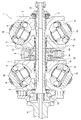
- FIG. 14 shows a second example of a conventional toroidal continuously variable transmission described in Japanese Patent Laid-Open No. 11-108139.
- the integral inner disk 8a has a pair of inner disks 8a provided between the inner peripheral surface of both axial ends of the inner disk 8a and the outer peripheral surface of the intermediate axial section of the rotary shaft 2a.
- a radial needle bearing 16 is rotatably supported around an intermediate portion in the axial direction of the rotary shaft 2a. Both ends in the axial direction of the inner disk 8a are rotatably supported by a pair of support columns 17 and a pair of thrust angular ball bearings 18 in a casing that houses the toroidal continuously variable transmission 1.
- Both ends of the pair of columns 17 are coupled and fixed to an actuator body 19 and a connecting plate 20 fixed to the casing, respectively, and trunnions 10 (see FIG. 13) are disposed on both sides in the axial direction of the pair of columns 17.
- a pair of support plates 21 for supporting both end portions of the two are supported.
- JP 2004-257533 A Japanese Patent Laid-Open No. 11-108139
- the traction coefficient of the traction portion which is a rolling contact portion between the pair of axially outer surfaces of the inner disk 8 and the peripheral surface of the power roller 9, is improved to improve the transmission efficiency.
- improvement there is room for improvement in terms of improving That is, in order to improve the traction coefficient and improve the transmission efficiency, there exists 1 between the axial inner side surface of the pair of outer disks 3 and the pair of axial outer surfaces of the inner disk 8. It is important to suppress variations in traction position and surface pressure between the pair of cavities between the pair of axial side surfaces of the inner disk 8 and the peripheral surface of the power roller 9.
- the pair of disk elements 7 of the inner disk 8 is a pair of radial needle bearings provided between the inner peripheral surface of the pair of disk elements 7 and the outer peripheral surface of the rotary shaft 2. 13 is rotatably supported around the rotary shaft 2.
- a sleeve 5 supported so as to be able to rotate synchronously with the pair of disk elements 7 by spline engagement on the inner side in the radial direction of the pair of disk elements 7 is a toroidal continuously variable transmission by a pair of angular ball bearings 14. It is supported so as to be rotatable with respect to a casing that houses the machine 1.
- the axially inner surfaces of the pair of disk elements 7 facing each other are abutted against the axially outer surface of the inner ring of the pair of angular ball bearings 14 via the pair of shim plates 15.
- the disk element 7 is positioned in the axial direction. Therefore, in the first example of the conventional structure, the pressing force generated by the pressing device 12 during the operation of the toroidal continuously variable transmission 1 due to the individual difference between the pair of angular ball bearings 14 or the difference in preload based on changes over time.
- the amount of axial displacement (deformation amount) of the pair of disk elements 7 varies, and the pair of axially outer surfaces of the inner disk 8 and the peripheral surface of the power roller 9 are between the pair of cavities.
- the position and surface pressure of the traction part may vary.
- an integrated inner disk 8a is employed, and the inner disk 8a is supported by a pair of thrust angular ball bearings 18. Therefore, regardless of the pressing force generated by the hydraulic pressing device 12a during operation of the toroidal continuously variable transmission 1a, the inner disk 8a is interposed between a pair of cavities existing on both sides in the axial direction of the inner disk 8a. It is possible to suppress variations in the position and surface pressure of the traction portion between the pair of axially outer side surfaces and the peripheral surfaces of the plurality of power rollers 9.
- both end portions of the inner disk 8a are rotatably supported by a pair of thrust angular ball bearings 18 with respect to a pair of support columns 17, so that the inner disk 8a can be rotated.
- the axial dimension of the supporting portion increases, which is disadvantageous from the viewpoint of reducing the size of the toroidal continuously variable transmission 1a.
- an object of the present invention is to realize a structure of a toroidal continuously variable transmission that facilitates miniaturization while ensuring transmission efficiency.
- the toroidal continuously variable transmission of the present invention includes a rotating shaft, a pair of outer disks, an inner disk, a pair of rolling bearing units, a plurality of power rollers, and a pair of preload applying mechanisms.
- Each of the pair of outer disks has an axial inner surface with a circular arc cross section, and is supported with respect to the rotating shaft so as to be able to rotate in synchronization with the rotating shaft.
- the inner disk has a pair of axially outer surfaces with an arc cross section facing the axially inner surfaces of the pair of outer disks, and is capable of rotating relative to the rotating shaft. On the other hand, it is supported.
- Each of the pair of rolling bearing units includes a radial rolling bearing that is capable of supporting an axial load, and includes an outer ring, an inner ring, and a plurality of rolling elements disposed between the outer ring and the inner ring.
- the disk is installed on the inner side in the radial direction of the inner disk so as to support the disk so as to be able to rotate relative to the rotating shaft.
- the plurality of power rollers are provided between the pair of outer disks and the inner disk, between the pair of outer disks and the pair of outer disks. It is arranged so that power can be transmitted.
- the preload applying mechanism elastically presses the outer ring or the inner ring of the radical rolling bearing in the axial direction.
- the inner disk can be configured integrally as a whole, or by combining a pair of disk elements.
- Each of the pair of rolling bearing units can be configured by combining a plurality of rolling bearings including the radial rolling bearing, or can be configured by only the radial rolling bearing.
- the preload imparting mechanism may be directly or otherwise disposed on the inner disk or the sleeve disposed around the rotation shaft so as to face the axial end surface of the outer ring or the inner ring and the axial end surface of the outer ring or the inner ring. It can comprise by the elastic member clamped between the level
- a radial gap can be provided between the outer peripheral surface of the outer ring and the inner peripheral surface of the inner disk facing the outer peripheral surface of the outer ring, or between the inner peripheral surface of the inner ring and the outer peripheral surface of the sleeve facing the inner peripheral surface of the inner ring.
- the dimension in the radial direction of the radial gap is large enough to prevent the preload of the pair of radial rolling bearings from becoming excessive regardless of the elastic deformation of the inner disk that occurs during operation of the toroidal continuously variable transmission.
- a structure of a toroidal continuously variable transmission is provided which is easy to reduce in size while ensuring transmission efficiency and durability.
- the preload applying mechanism elastically presses the outer ring or the inner ring of the radial rolling bearing constituting the pair of rolling bearing units in the axial direction to apply the axial preload to the radial rolling bearing. For this reason, for example, even if a dimensional difference occurs between the radial rolling bearings constituting the pair of rolling bearing units based on individual differences and aging, the dimensional difference can be absorbed, The preload of the radial rolling bearing can be maintained at an appropriate value. Therefore, during the operation of the toroidal continuously variable transmission according to the present invention, it is possible to suppress variation in the deformation amount of the pair of axially outer surfaces of the inner disk, so that the transmission efficiency of the toroidal continuously variable transmission is ensured. be able to.
- the toroidal continuously variable transmission it is possible to absorb a load that is to be input to the pair of radial rolling bearings based on deformation of the inner disk, so that the preload of the radial rolling bearing is excessive. And the surface pressure of the rolling contact portion of the radial rolling bearing can be prevented from becoming uneven in the circumferential direction, and the durability of the radial rolling bearing can be ensured. Durability can be secured.
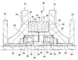
- FIG. 1 is a cross-sectional view showing an inner disk and a portion that rotatably supports the inner disk with respect to a rotating shaft and a casing in the first example of the embodiment of the present invention.
- FIG. 2 relates to the first example of the embodiment of the present invention, and explains the problem when the inner disk is rotatably supported by a radial rolling bearing installed on the inner side in the radial direction of the inner disk. It is sectional drawing for doing.
- FIG. 3 is a view similar to FIG. 1 for explaining a problem when the preload adjustment in the axial direction of the ball bearing for rotatably supporting the inner disk is performed by the shim plate.
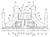
- FIG. 4 is a view similar to FIG. 1, showing a second example of the embodiment of the present invention.
- FIG. 1 is a cross-sectional view showing an inner disk and a portion that rotatably supports the inner disk with respect to a rotating shaft and a casing in the first example of the embodiment of the present invention.
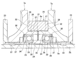
- FIG. 5 is a view similar to FIG. 1, showing a third example of the embodiment of the present invention.
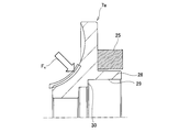
- FIG. 6 is a diagram corresponding to an enlarged view of a portion X in FIG. 5 showing a fourth example of the embodiment of the present invention.
- FIG. 7 is a view similar to FIG. 1, showing a fifth example of the embodiment of the present invention.
- FIG. 8 is a view similar to FIG. 1, showing a sixth example of the embodiment of the present invention.
- FIG. 9 is a view similar to FIG. 1, showing a seventh example of the embodiment of the present invention.
- FIG. 10 is a view similar to FIG. 1, showing an eighth example of the embodiment of the present invention.
- FIG. 11 is a diagram corresponding to the enlarged view of the Y part in FIG.
- FIG. 10 showing the ninth example of the embodiment of the present invention.
- FIG. 12 is a diagram corresponding to the enlarged view of the Z portion in FIG. 5, showing the tenth example of the embodiment of the present invention.
- FIG. 13 is a cross-sectional view showing a first example of a conventional toroidal continuously variable transmission.
- FIG. 14 is a cross-sectional view showing a second example of a conventional toroidal continuously variable transmission.
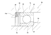
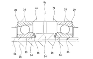
- FIG. 1 shows a first example of an embodiment of the present invention.
- the toroidal continuously variable transmission of this example includes a rotating shaft 2b, a pair of outer disks 3 (see FIG. 14), an inner disk 8b, and a plurality of power rollers 9.
- the pair of outer disks 3 is movable around the axis of the rotating shaft 2b so that the inner surfaces in the axial direction, each of which is a toroidal curved surface, face each other around the both ends in the axial direction of the rotating shaft 2b. Is supported with respect to the rotation shaft 2b so as to be able to rotate in synchronization with the rotation axis.
- the inner disk 8b has a pair of axially outer surfaces, each of which is a toroidal curved surface, opposed to an axially inner surface of the pair of outer disks 3, and can rotate relative to the rotating shaft 2b. Is supported against.
- Each power roller 9 has a pair of cavities (two in the axial direction) between an inner side surface in the axial direction of the pair of outer disks 3 and a pair of outer side surfaces in the axial direction of the inner disk 8b.
- the circumferential surface which is a spherical convex surface, is disposed so as to be sandwiched between one of the pair of outer disks 3 and one pair of shafts of the inner disk 8b facing the inner surface in the axial direction. It is in rolling contact with one of the direction outer surfaces.
- Each power roller 9 is rotatably supported with respect to the support member.
- Each of the support members is supported by a casing or a member fixed to the casing so as to be able to swing and swing around a pivot that is twisted with respect to the center axis of the pair of outer disk 3 and inner disk 8b. ing.
- a trunnion 10 as shown in FIG. 13 can be used as the support member.
- the outer side of one of the pair of outer disks 3 (left side in FIG. 14) is driven by the hydraulic pressing device 12a (see FIG. 14) while rotating the rotating shaft 2b.
- the disk 3 is pressed toward the other outer disk 3 (right side in FIG. 14).
- the pair of outer disks 3 rotate synchronously while being pressed toward each other.
- the rotation of the pair of outer disks 3 is transmitted to the inner disk 8b through the respective power rollers 9, and is taken out from the transmission gear 6a provided on the outer peripheral surface of the intermediate portion of the inner disk 8b.
- the power of the drive source can be input to the inner disk 8b and taken out from the pair of outer disks 3.
- the sleeve 5a is supported around the axially intermediate portion of the rotary shaft 2b in a state that allows relative rotation with respect to the rotary shaft 2b and prevents rotation with respect to the casing housing the toroidal continuously variable transmission.
- the rotary shaft 2b is supported on the radially inner side of the sleeve 5a supported in a state in which the rotation with respect to the casing is prevented so as to be capable of relative rotation with respect to the sleeve 5a.
- a pair of radial needle bearings 22 is provided between the both axial sides of the inner peripheral surface of the sleeve 5a and the outer peripheral surface of the rotary shaft 2b, and both axial ends of the sleeve 5a are provided at the sleeve 5a. It is supported and fixed to the casing via a pair of support members 23 supported in a state where relative rotation with respect to is prevented. An outward flange portion 24 projecting radially outward is provided at an axially intermediate portion of the outer peripheral surface of the sleeve 5a.
- the inner disk 8b is configured by combining a pair of disk elements 7a and an annular member 25.
- the outer surface in the axial direction facing the inner surface in the axial direction of the pair of outer disks 3 is a toroidal curved surface having a circular arc cross section.
- a small-diameter portion 26 whose outer diameter is smaller than that of the intermediate portion in the axial direction is provided at each of the inner end portions in the axial direction of the pair of disk elements 7a.
- the small diameter portion 26 has an outer peripheral surface as a male spline portion 27.
- the outer peripheral surface of the intermediate portion in the axial direction of the disk element 7a and the outer peripheral surface of the small diameter portion 26 are continuous by an outer diameter side step surface 28 facing inward in the axial direction.
- a fitting surface portion 29 having an inner diameter larger than that of the outer half portion in the axial direction is provided on the inner half portion in the axial direction of the inner peripheral surface of the pair of disk elements 7a.
- the inner peripheral surface of the outer half portion in the axial direction of the disk element 7a and the fitting surface portion 29 are continuous by an inner diameter side step surface 30 facing inward in the axial direction.
- the annular member 25 is provided with a transmission gear 6a on the outer peripheral surface, and a female spline portion 31 that engages with the male spline portion 27 of the pair of disk elements 7a on the inner peripheral surface. Further, the annular member 25 has annular convex portions 32 on both axial end surfaces. The annular member 25 is positioned relative to each other between the pair of disk elements 7a by abutting each of the front end surfaces of the projections 32 against the respective outer diameter side step surfaces 28 of the pair of disk elements 7a. The female spline part 31 of the annular member 25 is engaged with each male spline part 27 of the pair of disk elements 7a while adjusting the distance between the inner side surfaces of the pair of disk elements 7a.
- each of the pair of rolling bearing units for supporting the inner disk 8b with respect to the rotating shaft 2b is constituted only by a radial rolling bearing capable of supporting an axial load.
- the inner disk 8b is formed by a pair of ball bearings 33 having radial angular types with different contact angles, that is, a front combination type contact angle, around the sleeve 5a and around the rotary shaft 2b and the sleeve. It is supported so that it can rotate relative to 5a.
- Each inner ring 34 of the pair of ball bearings 33 is externally fitted to the sleeve 5a by an interference fit with the axially inner end face of the inner ring 34 abutting against both axial sides of the outward flange portion 24 of the sleeve 5a.
- each outer ring 35 of the pair of ball bearings 33 is fitted in each fitting surface portion 29 of the pair of disk elements 7a with a gap fit.
- the inner ring 34 may be externally fitted to the sleeve 5 a with a gap fit
- the outer ring 35 may be fitted to the fitting surface portion 29 with an interference fit.
- the toroidal continuously variable transmission of the present example presses the outer rings 35 of the pair of ball bearings 33 in a direction approaching each other in the axial direction (inward in the axial direction), thereby causing the pair of ball bearings 33 to move in the axial direction.
- a preload applying mechanism for applying the preload is provided.
- the preload applying mechanism elastically deforms a pair of conical disc springs 36 between the axially outer end surfaces of the outer rings 35 and the inner diameter side step surface 30 of the pair of disk elements 7a (elasticity). It is comprised by pinching in the state which was crushed automatically. That is, in this example, the pair of disc springs 36 constitutes an elastic member, and the inner diameter side step surface 30 of the pair of disk elements 7a constitutes a step surface.
- a pair of disc springs 36 elastically press the outer rings 35 inward in the axial direction (in a direction approaching each other), thereby applying an axial preload to the pair of ball bearings 33. Yes.
- the inner disk 8b is supported by a pair of ball bearings 33 installed on the inner side in the radial direction of the inner disk 8b so as to be relatively rotatable with respect to the rotating shaft 2b.
- the size of the inner disk 8b as compared with a structure in which both axial ends of the inner disk 8b are rotatably supported by a pair of thrust angular ball bearings 18.
- the preload applying mechanism elastically presses each outer ring 35 of the pair of ball bearings 33 inward in the axial direction to apply the preload in the axial direction to the pair of ball bearings 33. For this reason, for example, even when a dimensional difference occurs between the pair of ball bearings 33 based on individual differences or secular change, the dimensional difference is absorbed by the elastic deformation of the respective disc springs 36.
- the preload of the pair of ball bearings 33 can be maintained at an appropriate value. Thereby, when the toroidal continuously variable transmission is operated, variation in the deformation amount of the pair of ball bearings 33 based on the pressing force generated by the pressing device 12a can be suppressed, so that the pair of ball bearings 33 can rotate freely.
- a pair of axially outer sides of the inner disk 8b is located between a pair of cavities existing between the inner axial surface of the pair of outer disks 3 and the pair of outer axial surfaces of the inner disk 8b. Variations in the position and surface pressure of the traction portion between the side surface and the peripheral surface of the power roller 9 can be suppressed, and the transmission efficiency of the toroidal continuously variable transmission can be improved. Further, when the toroidal continuously variable transmission is operated, the preload of the pair of ball bearings 33 can be prevented from becoming excessive, and the durability of the pair of ball bearings 33 can be ensured satisfactorily. The durability of the toroidal continuously variable transmission can be secured satisfactorily. The reason for this will be described with reference to FIGS. 2 and 3 in addition to FIG.
- the force (normal force) Fc applied to the pair of disk elements 7a of the inner disk 8b based on the pressing force generated by the pressing device 12a is several tens kN ( Based on this force Fc, the pair of disk elements 7a has a contact point with the tip surface of each convex portion 32 of the annular member 25 as a fulcrum (about several tenths of a millimeter). Elastically deforms.
- the circumferential surface of the power roller 9 is in rolling contact with the radially inner half of the pair of axially outer surfaces of the inner disk 8b, the inner diameter side step surface 30 of the pair of disk elements 7a is axially Elastically deforms in the inward direction.
- Such elastic deformation of the pair of disk elements 7a is greatest when the peripheral surface of the power roller 9 is in rolling contact with the small-diameter end of the axially outer surface of the pair of disk elements 7a. Therefore, as shown in FIG. 3, when the preload adjustment of the pair of ball bearings 33 that rotatably support the pair of disk elements 7a is performed by the pair of shim plates 37, the preload of each ball bearing 33 is excessive. There is a possibility. Further, the elastic deformation amount of the pair of disk elements 7a is larger in the circumferential direction than in the phase where the power roller 9 is present and not present.
- the preload adjustment of the pair of ball bearings 33 is performed by the pair of shim plates 37
- the preload of the respective ball bearings 33 becomes non-uniform in the circumferential direction
- the inner ring raceway of each ball bearing 33 and The rolling element load applied to the outer ring raceway may also be non-uniform in the circumferential direction.
- the assembly of the toroidal continuously variable transmission is performed. There may be a change in dimensions between the time of operation and the time of operation.
- each ball bearing is associated with the thermal expansion of the components of the toroidal continuously variable transmission during operation of the toroidal continuously variable transmission.
- the 33 preload may be excessive.
- the bearing life of each of the pair of ball bearings 33 may be significantly reduced.
- the axially outer end surfaces of the outer rings 35 of the pair of ball bearings 33 and the inner diameter side step surfaces 30 of the pair of disk elements 7a are provided.
- the pair of disc springs 36 sandwiched between the pair of ball bearings 33 adjust the preload. For this reason, even when the inner diameter side step surfaces 30 of the pair of disk elements 7a are elastically deformed in the axially inward direction, the disc springs 36 are elastically deformed, whereby the pair of disk elements The elastic deformation of 7a can be absorbed, and the preload of each ball bearing 33 can be prevented from becoming excessive.
- the rolling load applied to the inner ring raceway and the outer ring raceway of the pair of ball bearings 33 can be made substantially uniform in the circumferential direction.
- the thermal expansion of the components of the toroidal continuously variable transmission can be absorbed during operation of the toroidal continuously variable transmission.
- each outer ring 35 is fitted into each fitting surface portion 29 of the pair of disk elements 7a with a gap fit, so that the pressing device 12a is generated during operation of the toroidal continuously variable transmission. Even when at least one of the pair of disk elements 7a is elastically deformed in the direction of reducing the diameter based on the pressing force, it is possible to prevent the preload of at least one of the pair of ball bearings 33 from becoming excessive. Therefore, according to the toroidal continuously variable transmission of this example, the bearing life of the pair of ball bearings 33 can be sufficiently ensured.
- FIG. 4 shows a second example of the embodiment of the present invention.
- both end surfaces in the axial direction of the annular member 25a of the inner disk 8c are annular flat surfaces.
- a pair of disk elements is sandwiched between a pair of shim plates 38 between the axially opposite end faces of the annular member 25a and the respective outer diameter side step surfaces 28 of the pair of disk elements 7a.
- Positioning of the relative positions of 7a, that is, adjustment of the distance between the axially outer surfaces of the pair of disk elements 7a is achieved.
- the configuration and operation of the other parts are the same as in the first example of the embodiment.
- FIG. 5 shows a third example of the embodiment of the present invention.
- the axially inner end surfaces of the pair of disk elements 7a of the inner disk 8d are brought into contact with each other, thereby positioning the relative positions of the pair of disk elements 7a.
- the configuration and operation of the other parts are the same as in the first example of the embodiment.
- FIG. 6 shows a fourth example of the embodiment of the present invention.
- the preload applying mechanism for applying the axial preload to the pair of ball bearings 33 includes the inner diameter side step surface 30 of the pair of disk elements 7a of the inner disk 8b and the outer ring 35 of the pair of ball bearings 33. Are sandwiched between a shim plate 15a and a disc spring 36, respectively.
- the outer surface in the axial direction of the shim plate 15 a is abutted against the stepped surface 30 on the inner diameter side of the disk element 7 a, and the inner surface in the axial direction of the shim plate 15 a and the outer end surface in the axial direction of the outer ring 35 of the pair of ball bearings 33.
- the disc springs 36 are sandwiched in an elastically deformed state.
- the outer ring 35 is elastically pressed toward the inner side in the axial direction by the disc spring 36, and an axial preload is applied to the ball bearing 33.
- the configuration and operation of the other parts are the same as in the first example of the embodiment.
- FIG. 7 shows a fifth example of the embodiment of the present invention.
- the entire inner disk 8e is integrally formed. That is, a transmission gear 6a is formed on the outer peripheral surface of the axially intermediate portion having a toroidal curved surface having a circular arc cross section on the pair of axially outer surfaces of the inner disk 8e and having an outer diameter smaller than both axially opposite sides. Is provided.
- a pair of locking grooves 39 are formed on both sides in the axial direction on the inner peripheral surface of the inner disk 8e in the circumferential direction.
- the inner peripheral surface of the inner disk 8e is a single cylindrical surface whose inner diameter does not change in the axial direction except for a portion where a pair of locking grooves 39 are formed.
- the inner disk 8e is disposed around the sleeve 5a supported by a pair of front-side ball bearings 33 in a state where rotation with respect to the casing housing the toroidal continuously variable transmission is prevented, relative to the rotary shaft 2b and the sleeve 5a. Supported for rotation. That is, in the state where the axial inner end surfaces of the inner rings 34 of the pair of ball bearings 33 are abutted against both axial side surfaces of the outward flange portion 24 provided in the axially intermediate portion of the sleeve 5a, the inner rings The outer ring 35 of the pair of ball bearings 33 is fitted into the inner peripheral surface of the inner disk 8e with a gap fit.
- a cross section is provided between the axially outer end surface of each outer ring 35 of the pair of ball bearings 33 and the axially inner side surface of the pair of locking rings 40 locked in the pair of locking grooves 39.
- the pair of conical springs 36 are sandwiched in a state of being elastically deformed, and each outer ring 35 is elastically pressed toward the inside in the axial direction.
- a preload applying mechanism for applying an axial preload to the pair of ball bearings 33 is configured.
- the stepped surface is constituted by the axially inner side surfaces of the pair of locking rings 40. The configuration and operation of the other parts are the same as in the first example of the embodiment.
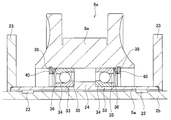
- FIG. 8 shows a sixth example of the embodiment of the present invention.
- the integrated inner disk 8f is supported around the sleeve 5a by a pair of back-bearing ball bearings 33a so as to be able to rotate relative to the sleeve 5a and the rotating shaft 2b.
- An inward flange portion 41 is provided at an axially intermediate portion of the inner peripheral surface of the inner disk 8f.
- An outward flange portion 24a is provided at a portion near the one end in the axial direction of the sleeve 5a (portion near the left end in FIG. 8), and a portion near the other end in the axial direction (portion near the right end in FIG.
- a locking groove 42 is provided.
- An inner ring 34a of the bearing 33a is externally fitted with an interference fit to a portion near one end of the sleeve 5a in the axial direction.
- the outer ring 35a of the ball bearing 33a on one axial side is fitted with a gap fit on the one axial side portion of the inner peripheral surface of the inner disk 8f.
- a conical disc-shaped disc spring 36 is sandwiched between one axial side surface of the inward flange portion 41 of the inner disk 8f and the axial inner end surface of the outer ring 35a of the ball bearing 33a on one axial side in an elastically deformed state. Has been.
- the outer ring 35a of the ball bearing 33a on the other side in the axial direction is fitted in the other side portion in the axial direction on the inner peripheral surface of the inner disk 8f with a gap fit.
- the inner ring 34a of the ball bearing 33a on the other axial side is externally fitted with an interference fit to the portion near the other end of the sleeve 5a in the axial direction.
- a locked locking ring 43 is abutted.
- a conical disk-shaped disc spring 36 is elastically deformed between the other axial side surface of the inward flange portion 41 of the inner disk 8f and the inner axial end surface of the outer ring 35a of the ball bearing 33a on the other axial direction side. It is pinched.
- both axial side surfaces of the inward flange portion 41 constitute a step surface.
- Other configurations and operations are the same as those of the first example of the embodiment and the fifth example of the embodiment.
- FIG. 9 shows a seventh example of the embodiment of the invention.
- the pair of rolling bearing units is constituted by only a pair of tapered roller bearings 44.
- the inner disk 8b formed by combining the pair of disk elements 7a and the annular member 25 is rotated around the sleeve 5a by a pair of tapered roller bearings 44 having a front combination type contact angle. 2b and the sleeve 5a are supported so as to be able to rotate relative to each other.
- the toroidal continuously variable transmission of this example has a pair of tapered roller bearings 44 between a pair of tapered outer roller bearings 44 and an outer peripheral axial surface of each outer ring, and a pair of disk elements 7 and a pair of disk elements 7.
- the outer rings of the pair of tapered roller bearings 44 are elastically pressed inward in the axial direction.
- a preload applying mechanism for applying an axial preload to the pair of tapered roller bearings 44 is configured.
- the configuration and operation of the other parts are the same as in the first example of the embodiment.
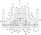
- FIG. 10 shows an eighth example of the embodiment of the present invention.
- the inner disk 8g formed by combining the pair of disk elements 7b and the annular member 25 can be rotated around the sleeve 5a by the pair of rolling bearing units 45 relative to the rotary shaft 2b and the sleeve 5a. It is supported by.
- a fitting surface portion 46 having an inner diameter larger than that of the outer end portion is provided at an axially intermediate portion of each inner peripheral surface of the pair of disk elements 7b, and the pair of disk elements 7b
- a cylindrical surface portion 47 having an inner diameter larger than that of the fitting surface portion 46 is provided at the inner end portion in the axial direction of each inner peripheral surface.
- the pair of rolling bearing units 45 includes a pair of cylindrical roller bearings 48 and a pair of ball bearings 33b having a front combination type contact angle.
- the pair of cylindrical roller bearings 48 includes an outer ring raceway formed on the inner peripheral surface of the pair of outer rings 49 by fitting a pair of outer rings 49 into the fitting surface portions 46 of the pair of disk elements 7b with an interference fit.
- the plurality of cylindrical rollers 50 are arranged in the circumferential direction between the outer peripheral surface of the sleeve 5a.
- the pair of cylindrical roller bearings has a pair of outer rings fitted inside the fitting surface portions of the pair of disk elements with an interference fit, and a pair of inner rings are fitted onto the sleeve with an fit.
- a plurality of cylindrical rollers may be arranged in the circumferential direction between an outer ring raceway formed on the inner peripheral surface of the pair of outer rings and an inner ring raceway formed on the outer peripheral surface of the pair of inner rings.
- the pair of ball bearings 33b is a state in which the axially inner end surfaces of the pair of inner rings 34b are abutted against both axial surfaces of the outward flange portion 24 provided at the intermediate portion of the sleeve 5a.
- the pair of inner rings 34b are externally fitted to the sleeve 5a by an interference fit.
- the outer peripheral surfaces of the pair of outer rings 35b are opposed to the cylindrical surface portions 47 of the pair of disk elements 7b via a radial gap.
- the section is conical between the stepped surface 51 that continues the fitting surface portion 46 and the cylindrical surface portion 47 of the pair of disk elements 7b and the axially outer end surface of each outer ring 35b of the pair of ball bearings 33b.
- the pair of trapezoidal disc springs 36 By holding the pair of trapezoidal disc springs 36 in an elastically deformed state, the pair of outer rings 35bb are elastically pressed toward the inside in the axial direction.
- a preload applying mechanism for applying an axial preload to the pair of ball bearings 33b is configured.
- the dimension of the radial gap in the radial direction constitutes a pair of radial rolling bearings regardless of the elastic deformation of the pair of disk elements 7b constituting the inner disk 8g that occurs during operation of the toroidal continuously variable transmission.
- the size of the pair of ball bearings 33b is set so as to prevent an excessive preload.
- the configuration and operation of the other parts are the same as in the first example of the embodiment.
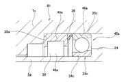
- FIG. 11 shows a ninth example of the embodiment of the present invention.
- an inner disk 8h formed by combining a pair of disk elements 7c and an annular member 25 (see FIG. 1) is provided around the sleeve 5a by a pair of rolling bearing units 45a.
- the rotary shaft 2b (see FIG. 1) and the sleeve 5a are supported so as to be capable of relative rotation.
- Each of the pair of disk elements 7c is provided with a fitting surface portion 46a in the inner half of the inner circumferential surface in the axial direction, and is directed inward in the axial direction at the outer end portion in the axial direction of the fitting surface portion 46a.
- An inner diameter side step surface 30a is provided.
- Each of the pair of rolling bearing units 45a includes a cylindrical roller bearing 48a and a ball bearing 33c.
- the cylindrical roller bearing 48a is configured by fitting the outer ring 49a into the fitting surface portion 46a by interference fitting in a state where the outer end surface in the axial direction of the outer ring 49a abuts against the inner diameter side step surface 30a.
- a plurality of cylindrical rollers 50 are disposed so as to roll freely.
- the ball bearing 33c which is a radial rolling bearing, has the inner ring 34c abutted against the sleeve 5a in a state in which the inner end face in the axial direction of the inner ring 34c is abutted against the outer surface in the axial direction of the outward flange 24 provided at the intermediate part of the sleeve 5a. It is fitted by interference fit.
- a conical disc spring 36 is sandwiched between the outer end surface of the outer ring 35c of the ball bearing 33c and the inner end surface of the outer ring 49a of the cylindrical roller bearing 48a in an elastically deformed state.
- the disc spring 36 constitutes a preload application mechanism that applies an axial preload to the ball bearing 33c so as to elastically press the outer ring 35c inward in the axial direction.
- a step surface is constituted by the axially inner end surface of the outer ring 49a of the cylindrical roller bearing 48a.
- the configuration and operation of the other parts are the same as in the first example of the embodiment.
- FIG. 12 shows a tenth example of the embodiment of the present invention.
- an inner disk 8b formed by combining a pair of disk elements 7a and an annular member 25 (see FIG. 1) is provided by a pair of ball bearings 33 having a front combination type contact angle.
- the sleeve 5a is supported around the rotation shaft 2b and the sleeve 5a so as to be rotatable relative to the sleeve 5a.
- each outer ring 35 is in the disk element 7a in a state in which the axially outer end surfaces of the outer rings 35 of the pair of ball bearings 33 are in contact with the inner diameter side step surfaces 30 of the pair of disk elements 7a.
- the fitting surface portion 29 is fitted with an interference fit.
- Each inner ring 34 of the pair of ball bearings 33 is externally fitted to the sleeve 5a with a gap fit.
- a pair of conical disc springs 36 are sandwiched between the axially inner end surfaces of the inner rings 34 and the axially opposite side surfaces of the outward flange portion 24 of the sleeve 5a in an elastically deformed state. Yes. Then, the pair of disc springs 36 apply an axial preload to the pair of ball bearings 33 so as to elastically press the inner rings 34 in a direction away from each other (axially outward).
- a preload application mechanism is configured.
- a step surface is formed by both side surfaces in the axial direction of the outward flange portion 24a of the sleeve 5a. The configuration and operation of the other parts are the same as in the first example of the embodiment.
Landscapes
- Engineering & Computer Science (AREA)
- General Engineering & Computer Science (AREA)
- Mechanical Engineering (AREA)
- Friction Gearing (AREA)
Priority Applications (1)
| Application Number | Priority Date | Filing Date | Title |
|---|---|---|---|
| US16/340,411 US11359703B2 (en) | 2016-11-18 | 2017-11-09 | Toroidal conrtinuously variable transmission |
Applications Claiming Priority (2)
| Application Number | Priority Date | Filing Date | Title |
|---|---|---|---|
| JP2016224654A JP6745708B2 (ja) | 2016-11-18 | 2016-11-18 | トロイダル型無段変速機 |
| JP2016-224654 | 2016-11-18 |
Publications (1)
| Publication Number | Publication Date |
|---|---|
| WO2018092681A1 true WO2018092681A1 (ja) | 2018-05-24 |
Family
ID=62145237
Family Applications (1)
| Application Number | Title | Priority Date | Filing Date |
|---|---|---|---|
| PCT/JP2017/040498 Ceased WO2018092681A1 (ja) | 2016-11-18 | 2017-11-09 | トロイダル無段変速機 |
Country Status (3)
| Country | Link |
|---|---|
| US (1) | US11359703B2 (enExample) |
| JP (1) | JP6745708B2 (enExample) |
| WO (1) | WO2018092681A1 (enExample) |
Cited By (1)
| Publication number | Priority date | Publication date | Assignee | Title |
|---|---|---|---|---|
| CN109519781A (zh) * | 2018-11-30 | 2019-03-26 | 浙江海洋大学 | 一种救援船舶用双头搜索灯安装架 |
Families Citing this family (5)
| Publication number | Priority date | Publication date | Assignee | Title |
|---|---|---|---|---|
| JP6756580B2 (ja) * | 2016-10-27 | 2020-09-16 | 川崎重工業株式会社 | トロイダル無段変速機 |
| EP3604857A4 (en) * | 2017-03-21 | 2020-12-09 | NSK Ltd. | PRESSURE DEVICE FOR CONTINUOUSLY VARIABLE TOROIDAL TRANSMISSION |
| CN110332231B (zh) * | 2019-07-15 | 2021-02-26 | 河北工业大学 | 一种可主动调节温度和预紧力的轴承组 |
| IT201900016145A1 (it) * | 2019-09-12 | 2021-03-12 | Ge Avio Srl | Ammortizzatore di un sistema assialmente iperstatico |
| US20220341467A1 (en) * | 2021-04-23 | 2022-10-27 | Schaeffler Technologies AG & Co. KG | Bearing with integrated axial preload and method thereof |
Citations (2)
| Publication number | Priority date | Publication date | Assignee | Title |
|---|---|---|---|---|
| JP2004257533A (ja) * | 2003-02-27 | 2004-09-16 | Nsk Ltd | トロイダル型無段変速機及び無段変速装置 |
| JP2016080117A (ja) * | 2014-10-21 | 2016-05-16 | 日本精工株式会社 | トロイダル型無段変速機 |
Family Cites Families (8)
| Publication number | Priority date | Publication date | Assignee | Title |
|---|---|---|---|---|
| JP3458673B2 (ja) | 1997-10-07 | 2003-10-20 | 日産自動車株式会社 | トロイダル型無段変速機の組立方法 |
| GB9904666D0 (en) * | 1999-03-01 | 1999-04-21 | Torotrak Dev Ltd | Bearing support for infinitely-variable-ratio transmission output discs |
| GB2361510A (en) * | 2000-04-19 | 2001-10-24 | Torotrak Dev Ltd | A continuously-variable-ratio, toroidal race rolling traction transmission |
| US6896415B2 (en) * | 2001-07-10 | 2005-05-24 | Nsk, Ltd. | Rolling bearing and bearing apparatus |
| DE10259710A1 (de) * | 2002-12-19 | 2004-07-15 | Robert Bosch Gmbh | Elektrische Maschine |
| US20120144939A1 (en) * | 2010-12-13 | 2012-06-14 | Arne Lars Jonas Kullin | Double Bearing Assembly for Rotating Shaft |
| EP2508768B1 (de) * | 2011-03-21 | 2013-06-05 | Maxon Motor AG | Federscheibe sowie Lagervorrichtung mit einer Federscheibe |
| JP2015090159A (ja) | 2013-11-05 | 2015-05-11 | 日本精工株式会社 | トロイダル型無段変速機 |
-
2016
- 2016-11-18 JP JP2016224654A patent/JP6745708B2/ja active Active
-
2017
- 2017-11-09 US US16/340,411 patent/US11359703B2/en active Active
- 2017-11-09 WO PCT/JP2017/040498 patent/WO2018092681A1/ja not_active Ceased
Patent Citations (2)
| Publication number | Priority date | Publication date | Assignee | Title |
|---|---|---|---|---|
| JP2004257533A (ja) * | 2003-02-27 | 2004-09-16 | Nsk Ltd | トロイダル型無段変速機及び無段変速装置 |
| JP2016080117A (ja) * | 2014-10-21 | 2016-05-16 | 日本精工株式会社 | トロイダル型無段変速機 |
Cited By (2)
| Publication number | Priority date | Publication date | Assignee | Title |
|---|---|---|---|---|
| CN109519781A (zh) * | 2018-11-30 | 2019-03-26 | 浙江海洋大学 | 一种救援船舶用双头搜索灯安装架 |
| CN109519781B (zh) * | 2018-11-30 | 2020-09-25 | 浙江海洋大学 | 一种救援船舶用双头搜索灯安装架 |
Also Published As
| Publication number | Publication date |
|---|---|
| US20190234496A1 (en) | 2019-08-01 |
| US11359703B2 (en) | 2022-06-14 |
| JP2018080794A (ja) | 2018-05-24 |
| JP6745708B2 (ja) | 2020-08-26 |
Similar Documents
| Publication | Publication Date | Title |
|---|---|---|
| WO2018092681A1 (ja) | トロイダル無段変速機 | |
| WO2012111562A1 (ja) | トロイダル型無段変速機 | |
| WO2012098977A1 (ja) | 電動式直動アクチュエータおよび電動式ディスクブレーキ装置 | |
| JP6117991B2 (ja) | トロイダル無段変速機 | |
| JP6756580B2 (ja) | トロイダル無段変速機 | |
| JP6252227B2 (ja) | トロイダル型無段変速機 | |
| JP6528358B2 (ja) | トロイダル型無段変速機 | |
| JP7753072B2 (ja) | トロイダル型無段変速機 | |
| JP7775787B2 (ja) | トロイダル型無段変速機 | |
| JP6372304B2 (ja) | トロイダル型無段変速機 | |
| WO2015122291A1 (ja) | トロイダル型無段変速機 | |
| JP6458443B2 (ja) | トロイダル型無段変速機 | |
| JP4524743B2 (ja) | トロイダル型無段変速機 | |
| JP4947492B2 (ja) | トロイダル型無段変速機 | |
| JP2025099042A (ja) | トロイダル型無段変速機 | |
| WO2015052950A1 (ja) | シングルキャビティ式トロイダル型無段変速機 | |
| JP6528359B2 (ja) | トロイダル型無段変速機 | |
| JP4587119B2 (ja) | トロイダル型無段変速機 | |
| JP5621358B2 (ja) | トロイダル型無段変速機 | |
| JP6561554B2 (ja) | トロイダル型無段変速機 | |
| CN108571512B (zh) | 旋转轴结构 | |
| JP6183163B2 (ja) | トロイダル型無段変速機 | |
| JP2024120463A (ja) | トロイダル型無段変速機 | |
| JP6528361B2 (ja) | トロイダル型無段変速機 | |
| JP6519333B2 (ja) | トロイダル型無段変速機 |
Legal Events
| Date | Code | Title | Description |
|---|---|---|---|
| 121 | Ep: the epo has been informed by wipo that ep was designated in this application |
Ref document number: 17870938 Country of ref document: EP Kind code of ref document: A1 |
|
| NENP | Non-entry into the national phase |
Ref country code: DE |
|
| 122 | Ep: pct application non-entry in european phase |
Ref document number: 17870938 Country of ref document: EP Kind code of ref document: A1 |