WO2018092266A1 - 睡眠アシスト装置 - Google Patents
睡眠アシスト装置 Download PDFInfo
- Publication number
- WO2018092266A1 WO2018092266A1 PCT/JP2016/084256 JP2016084256W WO2018092266A1 WO 2018092266 A1 WO2018092266 A1 WO 2018092266A1 JP 2016084256 W JP2016084256 W JP 2016084256W WO 2018092266 A1 WO2018092266 A1 WO 2018092266A1
- Authority
- WO
- WIPO (PCT)
- Prior art keywords
- assist device
- core portion
- sleep assist
- core
- unit
- Prior art date
- Legal status (The legal status is an assumption and is not a legal conclusion. Google has not performed a legal analysis and makes no representation as to the accuracy of the status listed.)
- Ceased
Links
Images


Classifications
-
- A—HUMAN NECESSITIES
- A61—MEDICAL OR VETERINARY SCIENCE; HYGIENE
- A61M—DEVICES FOR INTRODUCING MEDIA INTO, OR ONTO, THE BODY; DEVICES FOR TRANSDUCING BODY MEDIA OR FOR TAKING MEDIA FROM THE BODY; DEVICES FOR PRODUCING OR ENDING SLEEP OR STUPOR
- A61M21/00—Other devices or methods to cause a change in the state of consciousness; Devices for producing or ending sleep by mechanical, optical, or acoustical means, e.g. for hypnosis
- A61M21/02—Other devices or methods to cause a change in the state of consciousness; Devices for producing or ending sleep by mechanical, optical, or acoustical means, e.g. for hypnosis for inducing sleep or relaxation, e.g. by direct nerve stimulation, hypnosis, analgesia
Definitions
- the present invention relates to a sleep assist device.
- the conventional sleep assist device a sensor that detects biological information of the subject and a sound source device that outputs a sound signal corresponding to the biological information are configured separately. For this reason, it is difficult to put together the sleep assist device in a compact manner, and there is a problem in that the sleep assist device has low transportability and storage property.
- This invention is made
- the sleep assist device includes a rod-shaped core part, a sheet-like sensor that is connected to the core part so as to be rewound and detects biological information of the subject, and the core part. And a sound generator that outputs a sound signal corresponding to the biological information of the subject detected by the sheet sensor.
- the sleep assist device since the sound generation unit is arranged in the core unit and the sheet-like sensor can be wound around the core unit, the sleep assist device can be compactly assembled. Therefore, it is possible to improve the transportability and storage performance of the sleep assist device.
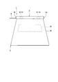
- FIG. 1 is a perspective view showing a sleep assist device according to an embodiment of the present invention. It is a block diagram of the sleep assist device concerning one embodiment of the present invention.
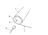
- the sleep assist device of FIG. 1 it is a principal part enlarged view which shows the one end side of the core part in an axial direction.
- the sleep assist device of FIG. 1 it is a principal part enlarged view which shows the other end side of the core part in an axial direction.
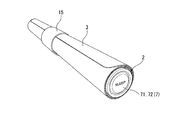
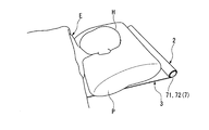
- the sleep assist device of FIG. 1 it is a perspective view which shows the state which wound up the sheet-like sensor on the core part. It is a perspective view which shows an example of the use condition of the sleep assist apparatus of FIG.
- the sleep assist device 1 of the present embodiment includes a rod-shaped core portion 2, a sheet-like sensor 3, and a sound source portion (sound generating portion) 4.
- the sleep assist device 1 according to the present embodiment includes an estimation unit (biological information processing unit) 5.
- the sleep assist device 1 of the present embodiment includes a speaker 6.
- the sleep assist device 1 of the present embodiment includes a setting unit 7.
- the sleep assist device 1 of the present embodiment includes a display unit 8.
- the sleep assist device 1 of the present embodiment also includes an A / D conversion unit 9, an acquisition unit 10, a control unit 11, a storage unit 12, and a D / A conversion unit 13.
- the core part 2 should just be formed in the rod shape extended at least linearly.
- the core portion 2 may be formed in a circular shape when viewed from the axial direction as shown in FIGS. 3 and 4, but may be formed in an arbitrary polygonal shape such as a quadrangle or a hexagon.
- the core part 2 should just be comprised so that the sound source part 4 can be distribute
- the core portion 2 may be formed in a cylindrical shape having a hollow inside, or may be formed in a column shape having a hollow only in a part of the inside.
- the dimension of the axial direction of the core part 2 may be arbitrary, it may be 25 cm or more and 75 cm or less, for example. Moreover, the dimension of the axial direction of the core part 2 may be 58 cm or more and 75 cm or less, for example. Although the diameter dimension of the core part 2 may be arbitrary, it may be 20 mm or more and 130 mm or less, for example.
- the sheet-like sensor 3 is a sensor that detects biological information of the subject E such as body movement, respiration, and pulse.
- the sheet sensor 3 is a sensor that detects vibration (pressure fluctuation), for example.
- the sheet-like sensor 3 according to the present embodiment is arranged under the head H of the subject E, and receives biological information such as body movement, breathing, and pulse of the subject E transmitted from the head H.
- the pillow P is arranged between the sheet-like sensor 3 and the head H of the subject E, but this is not a limitation.
- the sheet-like sensor 3 has flexibility and is connected to the core portion 2 so as to be capable of being wound as illustrated in FIG. As illustrated in FIG. 3, an end portion (base end portion) 31 of the sheet-like sensor 3 positioned on the core portion 2 side is connected to a part of the core portion 2 in the circumferential direction.
- the (length dimension) may be set so that at least the head H of the subject E does not protrude from the top of the sheet sensor 3 in a state where the sheet sensor 3 is arranged below the head H of the subject E.
- the width dimension of the sheet sensor 3 along the axial direction of the core portion 2 is set to be equal to the axial dimension of the core portion 2.
- the sheet-like sensor 3 of the present embodiment includes a sensor main body 32 that is formed in a sheet shape and detects the biological information of the subject E, and the sensor main body is sandwiched from the thickness direction thereof. And a protective sheet 33 for protecting.
- the sensor body 32 is smaller than the protective sheet 33, but is not limited thereto.
- the A / D conversion unit 9 is configured by, for example, an analog-digital converter, and converts biological information detected by the sheet sensor 3 into a digital signal.
- the acquisition unit 10 supplies the converted digital signal to the estimation unit 5 and the control unit 11. Moreover, the acquisition part 10 may once accumulate
- the A / D conversion unit 9 and the acquisition unit 10 are arranged inside the core unit 2 (see FIG. 1).
- the A / D conversion unit 9 is electrically connected to the above-described sheet-like sensor 3 (particularly the sensor main body 32) by wiring (not shown).
- the estimation unit 5 processes the biological information of the subject E detected by the sheet sensor 3 and estimates the sleep state (sleep depth) of the subject E.
- the sleep state of the subject E is estimated based on information representing a state such as body movement or breathing included in the biological information output as a digital signal from the acquisition unit 10. Examples of the sleep state include “excitement”, “wakefulness”, “light sleep”, “deep sleep”, and “REM sleep”.
- the estimation unit 5 identifies which of these types the sleep state of the subject E corresponds.
- the estimation of the sleep state in the estimation unit 5 can be performed by a conventionally known method. At least a part of the processing in the estimation unit 5 may be executed in the control unit 11, for example. In this embodiment, the estimation part 5 is distribute
- the sound source unit 4 is arranged inside the core unit 2 (see FIG. 1) described above.
- the sound source unit 4 outputs a sound signal corresponding to the biological information of the subject E detected by the sheet sensor 3.
- the sound source unit 4 of the present embodiment outputs a sound signal based on the estimation result (sleep state) of the estimation unit 5.
- the sound signal may be generated according to the estimation result of the estimation unit 5 under the control of the control unit 11.
- the sound signal may have a sound frequency, a tempo, or the like adjusted according to an estimation result of the estimation unit 5.
- the sound signal is generated based on the sound content such as music or natural sound (for example, wind sound, wave sound, river murmur) stored in advance in the storage unit 12 in addition to the estimation result of the estimation unit 5, for example. Also good.
- the sound signal generated by the sound source unit 4 may be stored in the storage unit 12, for example.
- the storage unit 12 may be configured by a known recording medium such as a semiconductor recording medium or a magnetic recording medium. In this embodiment, the memory
- the sound source unit 4 of the present embodiment outputs the generated sound signal with two stereo channels.
- the D / A conversion unit 13 is composed of, for example, a digital / analog converter, and converts the sound signal generated in the sound source unit 4 into analog and outputs the analog signal.
- the first D / A conversion unit 131 converts the stereo left (L) signal generated by the sound source unit 4 into an analog signal and outputs the analog signal.
- the second D / A conversion unit 132 converts the stereo light (R) signal generated by the sound source unit 4 into an analog signal and outputs the analog signal.
- the D / A conversion unit 13 (131, 132) of the present embodiment is arranged inside the core unit 2 (see FIG. 1).
- the speaker 6 emits a sound corresponding to the sound signal output from the sound source unit 4.
- the first speaker 61 amplifies the left (L) signal output from the first D / A converter 131 with a built-in amplifier and emits the sound.
- the second speaker 62 amplifies the stereo light (R) signal output from the second D / A converter 132 with a built-in amplifier and emits the sound.
- the speaker 6 of the present embodiment is disposed inside the core unit 2.
- the speaker 6 is arranged so that sound emitted from the speaker 6 propagates away from the outer peripheral surface of the core portion 2 in the radial direction of the core portion 2.
- the sound direction of the speaker 6 that propagates away from the core portion 2 in the radial direction is a connection portion (base end portion 31; You may arrange
- the two speakers 61 and 62 are arranged with a space in the axial direction of the core portion 2.
- the interval between the two speakers 61 and 62 may be arbitrary, but may be set to be equal to or greater than the interval between both ears of the head H of the subject E, for example.
- the two speakers 61, 62 are, for example, so that the sound emitted from the two speakers 61, 62 propagates in a direction approaching each other in the axial direction of the core unit 2 as the distance from the core unit 2 in the radial direction of the core unit 2 increases. It may be arranged.
- the setting unit 7 performs various settings of the sleep assist device 1.
- the setting unit 7 of the present embodiment includes a power switch 71 and a rotary operator 72 as shown in FIG.
- the power switch 71 switches supply / stop of power to the sheet-like sensor 3, the sound source unit 4, the estimation unit 5, and the like.
- the rotary operator 72 adjusts the magnitude of the sound signal output from the sound source unit 4 (the magnitude of the sound emitted from the speaker 6).
- the power switch 71 is disposed so as to be exposed on one end face 2 a of the core portion 2 in the axial direction.
- the switching of power supply / stop by the power switch 71 may be performed by any operation, but in the present embodiment, it is performed by pressing the power switch 71 with respect to the core unit 2 in the axial direction. Is called.
- the rotary operator 72 may be provided separately from, for example, the power switch 71, but is configured by the power switch 71 in the present embodiment. That is, the rotary operation element 72 of the present embodiment is configured by the power switch 71 provided so as to be rotatable about the axis of the core unit 2. An arrow D1 in FIG. 3 indicates the direction of rotation of the power switch 71.
- the power switch 71 may be formed with a recess for hooking a finger, for example, so that the power switch 71 can be rotated with the finger or the like.
- the display unit 8 displays visual information corresponding to the biological information of the subject E.
- Visual information includes, for example, heart rate, frequency of breathing, sleep state, amount of sleep, and the like.
- the display unit 8 of the present embodiment is disposed on one end surface 2 a of the core unit 2 in the axial direction.
- the display unit 8 is formed in an annular shape surrounding the power switch 71.
- the display unit 8 of the present embodiment can show the visual information described above by changing the color, brightness, display area, or the like.
- the sleep assist device 1 of the present embodiment includes a power terminal 14 as shown in FIGS.
- a power supply wiring W for supplying power to the sheet sensor 3, the sound source unit 4, the estimation unit 5, and the like is connected to the power supply terminal 14.
- the power supply wiring W is detachable from the power supply terminal 14, but the present invention is not limited to this.
- the power terminal 14 is provided so as to be exposed on the other end surface 2b of the core portion 2 in the axial direction. In the illustrated example, the power terminal 14 is exposed on the bottom surface of the recess that is recessed in the axial direction of the core portion 2 from the other end surface 2b of the core portion 2, but is not limited thereto.
- the sleep assist device 1 of the present embodiment includes a fastener 15 that holds the sheet-like sensor 3 in a state of being wound around the core portion 2 as shown in FIG.
- the fastener 15 may have any configuration.
- the fastener 15 illustrated in FIG. 5 is formed in a belt shape in which the sheet sensor 3 is wound around the core portion 2 and then wound around the core portion 2.
- the acquisition unit 10, the control unit 11, the estimation unit 5, and the sound source unit 4 may be configured by a processing device such as a CPU (Central Processing Unit) or a dedicated electronic circuit, for example.
- the acquisition unit 10, the control unit 11, the estimation unit 5, and the sound source unit 4 may be configured by, for example, separate processing devices and electronic circuits, respectively. It may be configured by a circuit.
- the digital-analog converter that constitutes the A conversion unit 13 may be appropriately configured on a substrate and then disposed inside the core unit 2.
- the sleep assist device 1 of the present embodiment configured as described above, as illustrated in FIG. 6, at least the sheet sensor 3 is arranged below the head H of the subject E, and What is necessary is just to distribute
- the core portion 2 is placed on the head of the subject E so that the axial direction of the core portion 2 coincides with the left-right direction of the subject E as illustrated in FIG. It is good to be located on the top side of H.
- the sound source unit 4 is arranged in the core unit 2, and the sheet-like sensor 3 can be wound around the core unit 2.
- the sleep assist apparatus 1 can be put together compactly. Therefore, the transportability and storage property of the sleep assist device 1 can be improved.
- the subject E can easily carry the sleep assist device 1 to a destination such as a travel destination and use it. As a result, it is possible to sleep well even in unfamiliar places other than home.
- the estimation unit 5 and the speaker 6 are also arranged in the core unit 2. For this reason, the sleep assist device 1 can be further compacted to further improve the transportability and storage property of the sleep assist device 1.
- the two speakers 61 and 62 are arranged with an interval in the axial direction of the core portion 2. Thereby, another sound can be heard in the left and right ears of the subject E by arranging the core portion 2 so that the axial direction of the core portion 2 coincides with the left and right direction of the subject E.
- sounds emitted from the two speakers 61 and 62 approach each other in the axial direction of the core unit 2 as they move away from the core unit 2 in the radial direction of the core unit 2. Propagate in the direction. Thereby, the sound emitted from the two speakers 61 and 62 can be actively sent to the left and right ears of the subject E, respectively. In addition, the sound emitted from the speaker 6 can be prevented from propagating around the subject E. That is, it can be suppressed that a person other than the subject E feels uncomfortable due to the sound emitted from the speaker 6.
- the sound direction of the speaker 6 that propagates away from the core portion 2 in the radial direction is such that the sheet-like sensor 3 and the core portion 2 are in the circumferential direction of the core portion 2. Is set so as to be shifted by 90 ° or more and 180 ° or less with respect to the connecting portion. For this reason, in a state where the sheet-like sensor 3 is extended from the core portion 2 and the core portion 2 is arranged on the connecting portion between the sheet-like sensor 3 and the core portion 2, the sound emitted from the speaker 6 is Propagation toward the upper surface of a bed or the like in which this is disposed can be prevented. That is, in a state where the sheet-like sensor 3 is arranged under the head H of the subject E, the sound emitted from the speaker 6 can easily reach the ear of the subject E.
- the power switch 71 is disposed so as to be exposed on one end face 2a of the core portion 2 in the axial direction. Therefore, the subject E can easily grasp the position of the power switch 71 by simply reaching for the end of the core portion 2 in a lying posture without visually recognizing the power switch 71. Can be easily operated. Further, the sheet-like sensor 3 can be easily wound around the core portion 2 as compared with the case where the power switch 71 is arranged on the outer peripheral surface of the core portion 2.
- the power switch 71 also functions as the rotary operator 72 that adjusts the magnitude of the sound signal output from the sound generator. For this reason, the subject E can reach the end of the core portion 2 in a lying posture without recognizing the rotary operator 72 and rotate the rotary operator 72 to thereby generate a sound signal (speak from the speaker 6). Can be easily adjusted. In particular, compared with the case where the rotary operator 72 is provided separately from the power switch 71, the subject E can easily distinguish between the power switching operation and the sound signal adjustment operation without visual recognition.
- the power terminal 14 is disposed so as to be exposed on the other end surface 2b of the core portion 2 in the axial direction. For this reason, the power supply wiring W connected to the power supply terminal 14 becomes easy to extend in the direction away from the core part 2 in the axial direction. Thereby, it can prevent that the power supply wiring W interferes with the test subject E (especially head H). Further, the sheet-like sensor 3 can be easily wound around the core portion 2 as compared with the case where the power supply terminal 14 is arranged on the outer peripheral surface of the core portion 2.
- the axial dimension of the core portion 2 and the sheet-like sensor 3 is set to 25 cm or more, which is an average diameter dimension of the head H, so that the subject at bedtime
- the head H of E can be arranged on the sheet-like sensor 3, and the biological information of the subject E can be reliably detected by the sheet-like sensor 3.
- the axial dimension of the core part 2 and the sheet-like sensor 3 is set to 58 cm or more which is the average width dimension of the pillow P, the head H of the subject E even if the subject E turns over at bedtime. Can be effectively prevented from protruding from the sheet-like sensor 3.
- the size of the sleep assist device 1 is prevented from becoming excessively large, and the transportability and stowability of the sleep assist device 1 are hindered. Can be prevented.
- the sheet-like sensor 3, the sound source unit 4, the estimation unit 5, and the like can be easily placed inside the core unit 2 by setting the diameter of the core unit 2 to 20 mm or more. Can be arranged. On the other hand, when the diameter of the core part 2 is 130 mm or less, it is possible to prevent the sleepability of the sleep assist device 1 from being hindered.
- the display part 8 which displays the visual information according to the test subject's E biological information is distribute
- the display unit 8 of the present embodiment is disposed on one end surface 2a of the core unit 2 that is the same as the power switch 71 (rotating operator 72). Therefore, the subject E and the like can easily grasp the position of the power switch 71 (rotating operator 72) by the light of the display unit 8.
- the sleep assist device of the present invention may not include a speaker, for example. That is, the speaker may be a speaker such as a general audio device or a mobile terminal arranged outside the core unit, for example. In this case, the speaker may be connected to the sound source unit by wire or wireless, for example.
- the sleep assist device of the present invention may not include a D / A conversion unit, for example. That is, the D / A conversion unit may be arranged outside the core unit together with the speaker, for example. In this case, the D / A conversion unit may be connected to the sound source unit by, for example, wired or wireless.
- the sleep assist device of the present invention may not include a storage unit, for example. That is, the storage unit may be arranged outside the core unit, for example. In this case, the storage unit may be connected to the sound source unit by wire or wireless, for example.
- the storage unit may be included in an external device such as a mobile terminal or a personal computer. In this case, an external device may be connected to the sound source unit.
- the sleep assist device of the present invention may include a battery for supplying power to, for example, a sheet sensor, a sound source unit, an estimation unit, and the like.
- the battery may be disposed, for example, inside the core portion. In this case, the sleep assist device can be used even in an environment where power cannot be supplied from the outside.
- the sleep assist device of the present invention may include a hook-and-loop fastener provided at the distal end portion in the extending direction of the sheet-like sensor extending from the core portion, for example, instead of the fastener of the above embodiment.
- the sheet-like sensor can be held in a state of being wound around the core portion by the hook-and-loop fastener. That is, since it is not necessary to separately prepare a fastener as in the above embodiment, the sleep assist device can be easily handled.
- SYMBOLS 1 Sleep assist apparatus, 2 ... Core part, 2a ... One end surface, 2b ... The other end surface, 3 ... Sheet-like sensor, 4 ... Sound source part (sound generation part), 5 ... Estimation part (biological information processing part), 6, 61, 62 ... Speaker, 7 ... Setting unit, 8 ... Display unit, 14 ... Power supply terminal, 71 ... Power switch, 72 ... Rotary operator, E ... Subject, W ... Power supply wiring
Landscapes
- Health & Medical Sciences (AREA)
- Anesthesiology (AREA)
- Pain & Pain Management (AREA)
- Physics & Mathematics (AREA)
- Acoustics & Sound (AREA)
- Psychology (AREA)
- Engineering & Computer Science (AREA)
- Biomedical Technology (AREA)
- Heart & Thoracic Surgery (AREA)
- Hematology (AREA)
- Life Sciences & Earth Sciences (AREA)
- Animal Behavior & Ethology (AREA)
- General Health & Medical Sciences (AREA)
- Public Health (AREA)
- Veterinary Medicine (AREA)
- Mattresses And Other Support Structures For Chairs And Beds (AREA)
- Measurement Of The Respiration, Hearing Ability, Form, And Blood Characteristics Of Living Organisms (AREA)
- Measuring Pulse, Heart Rate, Blood Pressure Or Blood Flow (AREA)
Abstract
睡眠アシスト装置は、棒状のコア部と、前記コア部に対して巻き取り可能に接続され、被験者の生体情報を検知するシート状センサと、前記コア部の内部に配され、前記シート状センサで検知された被験者の生体情報に応じた音信号を出力する音発生部と、を備える。
Description
この発明は、睡眠アシスト装置に関する。
近年、体動、呼吸、心拍などの被験者の生体情報を検出すると共に、当該生体情報に応じた音を発生させて、睡眠の改善やリラクゼーション効果を付与する装置(睡眠アシスト装置)が提案されている。(例えば特許文献1参照)。
しかしながら、上記従来の睡眠アシスト装置では、被験者の生体情報を検出するセンサと、生体情報に応じた音信号を出力する音源装置とが、別個に構成されている。このため、睡眠アシスト装置をコンパクトにまとめることが難しく、睡眠アシスト装置の搬送性や収納性が低い、という問題がある。
本発明は、上述した事情に鑑みてなされたものであって、搬送性や収納性を向上できる睡眠アシスト装置を提供することを目的とする。
本発明の第一の態様の睡眠アシスト装置は、棒状のコア部と、前記コア部に対して巻き取り可能に接続され、被験者の生体情報を検知するシート状センサと、前記コア部の内部に配され、前記シート状センサで検知された被験者の生体情報に応じた音信号を出力する音発生部と、を備える。
本発明によれば、音発生部がコア部内に配されるため、また、シート状センサがコア部に対して巻き取り可能であるため、睡眠アシスト装置をコンパクトにまとめることができる。したがって、睡眠アシスト装置の搬送性や収納性を向上することができる。
以下、図1-6を参照して本発明の一実施形態について説明する。
図1,2に示すように、本実施形態の睡眠アシスト装置1は、棒状のコア部2と、シート状センサ3と、音源部(音発生部)4と、を備える。また、本実施形態の睡眠アシスト装置1は、推定部(生体情報処理部)5を備える。また、本実施形態の睡眠アシスト装置1は、スピーカ6を備える。また、本実施形態の睡眠アシスト装置1は、設定部7を備える。また、本実施形態の睡眠アシスト装置1は、表示部8を備える。また、本実施形態の睡眠アシスト装置1は、A/D変換部9、取得部10、制御部11、記憶部12、D/A変換部13も備える。
図1,2に示すように、本実施形態の睡眠アシスト装置1は、棒状のコア部2と、シート状センサ3と、音源部(音発生部)4と、を備える。また、本実施形態の睡眠アシスト装置1は、推定部(生体情報処理部)5を備える。また、本実施形態の睡眠アシスト装置1は、スピーカ6を備える。また、本実施形態の睡眠アシスト装置1は、設定部7を備える。また、本実施形態の睡眠アシスト装置1は、表示部8を備える。また、本実施形態の睡眠アシスト装置1は、A/D変換部9、取得部10、制御部11、記憶部12、D/A変換部13も備える。
コア部2は、少なくとも直線状に延びる棒状に形成されていればよい。コア部2は、図3,4等に示すように軸方向から見て円形状に形成されてもよいが、例えば四角形や六角形等の任意の多角形状に形成されてもよい。
コア部2は、少なくとも音源部4をコア部2の内部に配することができるように構成されていればよい。コア部2は、例えば内部全体が空洞である筒状に形成されてもよいし、例えば内部の一部のみに空洞がある柱状に形成されてもよい。
コア部2は、少なくとも音源部4をコア部2の内部に配することができるように構成されていればよい。コア部2は、例えば内部全体が空洞である筒状に形成されてもよいし、例えば内部の一部のみに空洞がある柱状に形成されてもよい。
コア部2の軸方向の寸法は、任意であってよいが、例えば25cm以上75cm以下であってよい。また、コア部2の軸方向の寸法は、例えば58cm以上75cm以下であってもよい。
コア部2の径寸法は、任意であってよいが、例えば20mm以上130mm以下であってよい。
コア部2の径寸法は、任意であってよいが、例えば20mm以上130mm以下であってよい。
シート状センサ3は、体動、呼吸、脈拍などの被験者Eの生体情報を検知するセンサである。シート状センサ3は、例えば振動(圧力変動)を検出するセンサである。本実施形態のシート状センサ3は、図6に示すように、被験者Eの頭部Hの下に配した状態で、頭部Hから伝わる被験者Eの体動、呼吸、脈拍等の生体情報を検出する。図6においては、シート状センサ3と被験者Eの頭部Hとの間に枕Pが配されているが、これに限ることはない。
シート状センサ3は、可撓性を有し、図5に例示するようにコア部2に対して巻き取り可能に接続されている。図3に例示するように、コア部2側に位置するシート状センサ3の端部(基端部)31は、コア部2のうち周方向の一部に接続されている。
図1,6に示すように、コア部2の軸方向に沿うシート状センサ3の幅寸法、及び、コア部2から繰り出した状態でコア部2から延びるシート状センサ3の延出方向の寸法(長さ寸法)は、シート状センサ3を被験者Eの頭部Hの下に配した状態で、少なくとも被験者Eの頭部Hがシート状センサ3上からはみ出さないように設定されればよい。本実施形態において、コア部2の軸方向に沿うシート状センサ3の幅寸法は、コア部2の軸方向の寸法と同等に設定されている。
図1に示すように、本実施形態のシート状センサ3は、シート状に形成されて被験者Eの生体情報を検知するセンサ本体32と、センサ本体をその厚さ方向から挟み込む等してセンサ本体を保護する保護シート33と、を備える。図示例ではセンサ本体32が保護シート33よりも小さいが、これに限ることはない。
図2に示すように、A/D変換部9は、例えばアナログデジタルコンバータで構成され、シート状センサ3で検知された生体情報をデジタル信号に変換する。取得部10は、変換されたデジタル信号を推定部5や制御部11に供給する。また、取得部10は、例えば変換されたデジタル信号を一旦蓄積してもよい。
本実施形態において、A/D変換部9及び取得部10は、コア部2(図1参照)の内部に配されている。A/D変換部9は、前述のシート状センサ3(特にセンサ本体32)と不図示の配線によって電気接続されている。
本実施形態において、A/D変換部9及び取得部10は、コア部2(図1参照)の内部に配されている。A/D変換部9は、前述のシート状センサ3(特にセンサ本体32)と不図示の配線によって電気接続されている。
推定部5は、シート状センサ3で検知された被験者Eの生体情報を処理して、被験者Eの睡眠状態(睡眠の深さ)を推定する。本実施形態では、取得部10からデジタル信号で出力された生体情報に含まれる体動や呼吸等の状態を表す情報に基づいて被験者Eの睡眠状態を推定する。睡眠状態には、例えば「興奮」、「覚醒」、「浅い眠り」、「深い眠り」、「レム睡眠」などの種類がある。推定部5は、被験者Eの睡眠状態がこれらの種類のいずれに該当するかを特定する。推定部5における睡眠状態の推定は、従来周知の方法で行うことが可能である。推定部5における処理の少なくとも一部は、例えば制御部11において実行されてもよい。
本実施形態において、推定部5はコア部2(図1参照)の内部に配されている。
本実施形態において、推定部5はコア部2(図1参照)の内部に配されている。
音源部4は、前述したコア部2(図1参照)の内部に配されている。音源部4は、シート状センサ3で検知された被験者Eの生体情報に応じた音信号を出力する。本実施形態の音源部4は、推定部5の推定結果(睡眠状態)に基づいて音信号を出力する。
音信号は、例えば制御部11の制御の元で、推定部5の推定結果に応じて生成されてよい。音信号は、例えば推定部5の推定結果に応じて音の周波数やテンポ等が調整されたものであってもよい。また、音信号は、例えば推定部5の推定結果に加え、記憶部12に予め記憶された音楽や自然音(例えば風の音、波の音、川のせせらぎ)などの音コンテンツに基づいて生成されてもよい。音源部4で生成された音信号は、例えば記憶部12に記憶されてもよい。記憶部12は、例えば半導体記録媒体、磁気式記録媒体等の公知の記録媒体によって構成されてよい。本実施形態において、記憶部12はコア部2(図1参照)の内部に配されている。
本実施形態の音源部4は、生成された音信号をステレオの2チャンネルで出力する。
音信号は、例えば制御部11の制御の元で、推定部5の推定結果に応じて生成されてよい。音信号は、例えば推定部5の推定結果に応じて音の周波数やテンポ等が調整されたものであってもよい。また、音信号は、例えば推定部5の推定結果に加え、記憶部12に予め記憶された音楽や自然音(例えば風の音、波の音、川のせせらぎ)などの音コンテンツに基づいて生成されてもよい。音源部4で生成された音信号は、例えば記憶部12に記憶されてもよい。記憶部12は、例えば半導体記録媒体、磁気式記録媒体等の公知の記録媒体によって構成されてよい。本実施形態において、記憶部12はコア部2(図1参照)の内部に配されている。
本実施形態の音源部4は、生成された音信号をステレオの2チャンネルで出力する。
D/A変換部13は、例えばデジタルアナログコンバータで構成され、音源部4において生成された音信号を、アナログに変換して出力する。本実施形態では、第一のD/A変換部131が、音源部4で生成されたステレオのレフト(L)の信号をアナログに変換して出力する。また、第二のD/A変換部132が、音源部4で生成されたステレオのライト(R)の信号をアナログに変換して出力する。
本実施形態のD/A変換部13(131,132)は、コア部2(図1参照)の内部に配されている。
本実施形態のD/A変換部13(131,132)は、コア部2(図1参照)の内部に配されている。
図1,2に示すように、スピーカ6は、音源部4から出力された音信号に応じた音を発する。スピーカ6は、例えば一つだけ設けられてもよいが、本実施形態では二つ設けられている。第一のスピーカ61は、第一のD/A変換部131から出力されたレフト(L)の信号を内蔵アンプで増幅させて放音する。第二のスピーカ62は、第二のD/A変換部132から出力されたステレオのライト(R)の信号を内蔵アンプで増幅させて放音する。
本実施形態のスピーカ6は、コア部2の内部に配されている。スピーカ6は、スピーカ6から発せられる音がコア部2の外周面からコア部2の径方向に離れるように伝播するように配されている。
スピーカ6は、例えばコア部2からその径方向に離れるように伝播するスピーカ6の音の向きがコア部2の周方向においてシート状センサ3とコア部2との接続部分(基端部31;図3参照)に対して90°以上180°以下だけずれるように、配されてもよい。
スピーカ6は、例えばコア部2からその径方向に離れるように伝播するスピーカ6の音の向きがコア部2の周方向においてシート状センサ3とコア部2との接続部分(基端部31;図3参照)に対して90°以上180°以下だけずれるように、配されてもよい。
また、本実施形態では、二つのスピーカ61,62が、コア部2の軸方向に間隔をあけて配されている。二つのスピーカ61,62同士の間隔は、任意であってよいが、例えば被験者Eの頭部Hの両耳同士の間隔と同等、又は、両耳同士の間隔よりも大きく設定されるとよい。二つのスピーカ61,62は、例えば二つのスピーカ61,62から発せられる音がコア部2からコア部2の径方向に離れるにしたがって、コア部2の軸方向に互いに近づく方向に伝播するように配されてもよい。
設定部7は、睡眠アシスト装置1の各種設定を行う。本実施形態の設定部7には、図3に示すように、電源スイッチ71や回転操作子72が含まれている。
電源スイッチ71は、シート状センサ3や音源部4、推定部5等への電力の供給/停止を切り換える。回転操作子72は、音源部4から出力される音信号の大きさ(スピーカ6から発せられる音の大きさ)を調整する。
電源スイッチ71は、シート状センサ3や音源部4、推定部5等への電力の供給/停止を切り換える。回転操作子72は、音源部4から出力される音信号の大きさ(スピーカ6から発せられる音の大きさ)を調整する。
図1,3に示すように、電源スイッチ71は、軸方向におけるコア部2の一方の端面2aに露出して配されている。本実施形態において、電源スイッチ71による電力の供給/停止の切り換えは、任意の操作で行われてよいが、本実施形態では電源スイッチ71をコア部2に対してその軸方向に押す操作によって行われる。
回転操作子72は、例えば電源スイッチ71と別個に設けられてもよいが、本実施形態では電源スイッチ71によって構成されている。すなわち、本実施形態の回転操作子72は、コア部2に対してその軸線を中心に回転可能に設けられた電源スイッチ71によって構成されている。図3における矢印D1は、電源スイッチ71の回転方向を示している。電源スイッチ71には、これを手指等で回転させることができるように、例えば手指を引っ掛けるための凹部が形成されてもよい。
図2,3に示すように、表示部8は、被験者Eの生体情報に応じた視覚情報を表示する。視覚情報には、例えば心拍数や呼吸の頻度、睡眠状態、睡眠量などが挙げられる。
本実施形態の表示部8は、図3に示すように、軸方向におけるコア部2の一方の端面2aに配されている。また、表示部8は、電源スイッチ71を囲む環状に形成されている。本実施形態の表示部8は、色や明るさ、表示領域を変化等させることで、上記の視覚情報を示すことができる。
本実施形態の表示部8は、図3に示すように、軸方向におけるコア部2の一方の端面2aに配されている。また、表示部8は、電源スイッチ71を囲む環状に形成されている。本実施形態の表示部8は、色や明るさ、表示領域を変化等させることで、上記の視覚情報を示すことができる。
さらに、本実施形態の睡眠アシスト装置1は、図1,4に示すように、電源端子14を備える。電源端子14には、シート状センサ3や音源部4、推定部5等に電力を供給するための電源配線Wが接続される。図示例では、電源配線Wが電源端子14に対して着脱可能とされているが、これに限ることはない。
電源端子14は、軸方向におけるコア部2の他方の端面2bに露出して設けられている。図示例では、電源端子14が、コア部2の他方の端面2bからコア部2の軸方向に窪む凹部の底面に露出しているが、これに限ることはない。
電源端子14は、軸方向におけるコア部2の他方の端面2bに露出して設けられている。図示例では、電源端子14が、コア部2の他方の端面2bからコア部2の軸方向に窪む凹部の底面に露出しているが、これに限ることはない。
さらに、本実施形態の睡眠アシスト装置1は、図5に示すように、シート状センサ3をコア部2に巻き付けた状態に保持する留め具15を備える。留め具15は、任意の構成であってよい。図5に例示する留め具15は、シート状センサ3をコア部2に巻き付けた上で、さらにコア部2に巻き付けるベルト状に形成されている。
本実施形態の睡眠アシスト装置1において、取得部10、制御部11、推定部5、音源部4は、例えばCPU(中央処理装置)等の処理装置若しくは専用の電子回路で構成されてよい。また、取得部10、制御部11、推定部5、音源部4は、例えばそれぞれ別個の処理装置や電子回路で構成されてもよいし、例えばこれらのうち少なくとも一部が共通の処理装置や電子回路で構成されてもよい。
さらに、取得部10、制御部11、推定部5、音源部4を構成する処理装置や電子回路、記憶部12を構成する記録媒体、A/D変換部9を構成するアナログデジタルコンバータ、D/A変換部13を構成するデジタルアナログコンバータは、適宜基板上に構成された上で、コア部2の内部に配されてもよい。
さらに、取得部10、制御部11、推定部5、音源部4を構成する処理装置や電子回路、記憶部12を構成する記録媒体、A/D変換部9を構成するアナログデジタルコンバータ、D/A変換部13を構成するデジタルアナログコンバータは、適宜基板上に構成された上で、コア部2の内部に配されてもよい。
以上のように構成される本実施形態の睡眠アシスト装置1を使用する際には、図6に例示するように、少なくともシート状センサ3が被験者Eの頭部Hの下に配され、かつ、コア部2が被験者Eの頭部Hの下に位置しないように配されればよい。すなわち、睡眠アシスト装置1を使用する際には、例えばコア部2を被験者Eの頭部Hの右側又は左側に位置させてもよい。
本実施形態の睡眠アシスト装置1を使用する際には、図6に例示するように、コア部2の軸方向が被験者Eの左右方向に一致するように、コア部2を被験者Eの頭部Hの頭頂部側に位置させるとよい。
本実施形態の睡眠アシスト装置1を使用する際には、図6に例示するように、コア部2の軸方向が被験者Eの左右方向に一致するように、コア部2を被験者Eの頭部Hの頭頂部側に位置させるとよい。
以上説明したように、本実施形態の睡眠アシスト装置1によれば、音源部4がコア部2内に配され、また、シート状センサ3がコア部2に対して巻き取り可能である。このため、睡眠アシスト装置1をコンパクトにまとめることができる。したがって、睡眠アシスト装置1の搬送性や収納性を向上することができる。
特に、睡眠アシスト装置1の搬送性が向上することで、被験者Eは、睡眠アシスト装置1を旅行先などの外出先に簡単に持ち運んで使用することが可能となる。これにより、自宅以外の慣れない場所でも充分に睡眠をとることができる。
特に、睡眠アシスト装置1の搬送性が向上することで、被験者Eは、睡眠アシスト装置1を旅行先などの外出先に簡単に持ち運んで使用することが可能となる。これにより、自宅以外の慣れない場所でも充分に睡眠をとることができる。
また、本実施形態の睡眠アシスト装置1によれば、推定部5やスピーカ6もコア部2内に配されている。このため、睡眠アシスト装置1をさらにコンパクトにまとめて、睡眠アシスト装置1の搬送性や収納性をさらに向上できる。
また、本実施形態の睡眠アシスト装置1によれば、二つのスピーカ61,62がコア部2の軸方向に間隔をあけて配されている。これにより、コア部2の軸方向が被験者Eの左右方向に一致するようにコア部2を配置することで、被験者Eの左右の耳に別の音を聞かせることができる。
また、本実施形態の睡眠アシスト装置1によれば、二つのスピーカ61,62から発せられる音を、コア部2からコア部2の径方向に離れるにしたがって、コア部2の軸方向に互いに近づく方向に伝播させる。これにより、二つのスピーカ61,62から発せられる音を、それぞれ被験者Eの左右の耳に積極的に届かせることができる。また、スピーカ6から発せられる音が、被験者Eの周囲に伝播することを抑制できる。すなわち、被験者E以外の人間等がスピーカ6から発せられる音によって不快に感じることを抑制できる。
また、本実施形態の睡眠アシスト装置1によれば、コア部2からその径方向に離れるように伝播するスピーカ6の音の向きが、コア部2の周方向においてシート状センサ3とコア部2との接続部分に対して90°以上180°以下だけずれるように設定されている。このため、シート状センサ3をコア部2から繰り出し、コア部2をシート状センサ3とコア部2との接続部分上に配した状態では、スピーカ6から発せられる音が、シート状センサ3やこれを配したベッド等の上面に向けて伝播することを防止できる。すなわち、シート状センサ3を被験者Eの頭部Hの下に配した状態において、スピーカ6から発せられる音が、被験者Eの耳に届きやすくなる。
また、本実施形態の睡眠アシスト装置1によれば、電源スイッチ71が軸方向におけるコア部2の一方の端面2aに露出して配されている。このため、被験者Eは、電源スイッチ71を視認しなくても、横たわった姿勢でコア部2の端部に手をのばすだけで、電源スイッチ71の位置を容易に把握でき、また、電源スイッチ71を容易に操作することができる。また、電源スイッチ71がコア部2の外周面に配される場合と比較して、簡単にシート状センサ3をコア部2に巻き取ることができる。
また、本実施形態の睡眠アシスト装置1によれば、電源スイッチ71が音発生部から出力される音信号の大きさを調整する回転操作子72としても機能する。このため、被験者Eは、回転操作子72を視認しなくても、横たわった姿勢でコア部2の端部に手をのばし、回転操作子72を回転することで、音信号(スピーカ6から発せられる音)の大きさを容易に調整することができる。特に、回転操作子72が電源スイッチ71と別個に設けられる場合と比較して、被験者Eは視認することなく、電源の切り換え操作と音信号の調整操作とを簡単に区別することができる。
また、本実施形態の睡眠アシスト装置1によれば、電源端子14が軸方向におけるコア部2の他方の端面2bに露出して配されている。このため、電源端子14に接続された電源配線Wはコア部2からその軸方向に離れる方向に延びやすくなる。これにより、電源配線Wが被験者E(特に頭部H)と干渉することを防止できる。また、電源端子14がコア部2の外周面に配される場合と比較して、簡単にシート状センサ3をコア部2に巻き取ることができる。
また、本実施形態の睡眠アシスト装置1によれば、コア部2及びシート状センサ3の軸方向の寸法を頭部Hの平均的な直径寸法である25cm以上とすることで、就寝時において被験者Eの頭部Hをシート状センサ3上に配することができ、被験者Eの生体情報を確実にシート状センサ3で検知することができる。また、コア部2及びシート状センサ3の軸方向の寸法を枕Pの平均的な横幅寸法である58cm以上とした場合には、就寝時に被験者Eが寝返りをうっても被験者Eの頭部Hがシート状センサ3からはみ出すことを効果的に防止できる。
一方、コア部2及びシート状センサ3の軸方向寸法を75cm以下とすることで、睡眠アシスト装置1の大きさが過度に大きくなることを防ぎ、睡眠アシスト装置1の搬送性及び収納性を阻害することを防止できる。
一方、コア部2及びシート状センサ3の軸方向寸法を75cm以下とすることで、睡眠アシスト装置1の大きさが過度に大きくなることを防ぎ、睡眠アシスト装置1の搬送性及び収納性を阻害することを防止できる。
また、本実施形態の睡眠アシスト装置1によれば、コア部2の径寸法を20mm以上とすることで、シート状センサ3や音源部4、推定部5等を簡単にコア部2の内部に配することができる。一方、コア部2の径寸法を130mm以下とすることで、睡眠アシスト装置1の搬送性及び収納性を阻害することを防止できる。
また、本実施形態の睡眠アシスト装置1によれば、被験者Eの生体情報に応じた視覚情報を表示する表示部8が、軸方向における前記コア部2の一方の端面2aに配されている。このため、表示部8を別途用意しなくても、被験者E等が、被験者Eの生体情報や生体情報に基づく各種情報(例えば睡眠状態等)を簡単に確認することができる。
また、本実施形態の表示部8は、電源スイッチ71(回転操作子72)と同じコア部2の一方の端面2aに配されている。このため、被験者E等は、電源スイッチ71(回転操作子72)の位置を、表示部8の光によって容易に把握することもできる。
また、本実施形態の表示部8は、電源スイッチ71(回転操作子72)と同じコア部2の一方の端面2aに配されている。このため、被験者E等は、電源スイッチ71(回転操作子72)の位置を、表示部8の光によって容易に把握することもできる。
以上、本発明について詳細に説明したが、本発明は上記実施形態に限定されるものではなく、本発明の趣旨を逸脱しない範囲において種々の変更を加えることが可能である。
本発明の睡眠アシスト装置は、例えばスピーカを備えなくてもよい。すなわち、スピーカは、例えばコア部の外側に配される一般的なオーディオ機器や携帯端末などのスピーカであってもよい。この場合、スピーカは、例えば有線又は無線によって音源部に接続されてもよい。
本発明の睡眠アシスト装置は、例えばD/A変換部を備えなくてもよい。すなわち、D/A変換部は、例えばスピーカと共にコア部の外側に配されるものであってもよい。この場合、D/A変換部は、例えば有線又は無線によって音源部に接続されてもよい。
本発明の睡眠アシスト装置は、例えば記憶部を備えなくてもよい。すなわち、記憶部は、例えばコア部の外側に配されてもよい。この場合、記憶部は、例えば有線又は無線によって音源部に接続されてもよい。また、記憶部は、例えば携帯端末やパーソナルコンピュータ等の外部機器に含まれるものであってもよい。この場合には、外部機器を音源部に接続してもよい。
本発明の睡眠アシスト装置は、例えばシート状センサや音源部、推定部等に電力を供給するためのバッテリーを備えてもよい。バッテリーは、例えばコア部の内部に配されているとよい。この場合には、外部から電力を供給できないような環境下においても、睡眠アシスト装置を使用することができる。
本発明の睡眠アシスト装置は、上記実施形態の留め具の代わりに、例えばコア部から延びるシート状センサの延出方向の先端部に設けられる面ファスナーを備えてもよい。この場合には、面ファスナーによってシート状センサをコア部に巻き付けた状態に保持することができる。すなわち、上記実施形態のような留め具を別途用意する必要が無くなるため、睡眠アシスト装置を容易に取り扱うことができる。
1…睡眠アシスト装置、2…コア部、2a…一方の端面、2b…他方の端面、3…シート状センサ、4…音源部(音発生部)、5…推定部(生体情報処理部)、6,61,62…スピーカ、7…設定部、8…表示部、14…電源端子、71…電源スイッチ、72…回転操作子、E…被験者、W…電源配線
Claims (13)
- 棒状のコア部と、
前記コア部に対して巻き取り可能に接続され、被験者の生体情報を検知するシート状センサと、
前記コア部の内部に配され、前記シート状センサで検知された被験者の生体情報に応じた音信号を出力する音発生部と、
を備える睡眠アシスト装置。 - 前記コア部の内部に配され、前記シート状センサで検知された被験者の生体情報を処理して被験者の睡眠状態を推定する生体情報処理部を備え、
前記音発生部は、前記生体情報処理部の推定結果に基づいて音信号を出力する請求項1に記載の睡眠アシスト装置。 - 前記コア部の内部に配され、前記音信号に応じた音を発するスピーカを備える請求項1又は請求項2に記載の睡眠アシスト装置。
- 前記スピーカが、前記コア部の軸方向に間隔をあけて二つ配されている請求項3に記載の睡眠アシスト装置。
- 二つの前記スピーカは、二つの前記スピーカから発せられる音が、前記コア部から前記コア部の径方向に離れるにしたがって、前記コア部の軸方向において互いに近づく方向に伝播するように、配されている請求項4に記載の睡眠アシスト装置。
- 前記スピーカは、前記コア部の外周面から外側に伝播する前記スピーカの音の向きが、前記コア部の周方向において前記シート状センサと前記コア部との接続部分に対して90°以上180°以下だけずれるように、配されている請求項4又は請求項5に記載の睡眠アシスト装置。
- 軸方向における前記コア部の一方の端面に露出して配され、前記シート状センサ、前記音発生部への電力の供給/停止を切り換える電源スイッチを備える請求項1から請求項6のいずれか一項に記載の睡眠アシスト装置。
- 前記電源スイッチが、前記コア部に対してその軸線を中心に回転可能に設けられることで、前記音発生部から出力される音信号の大きさを調整する回転操作子として機能する請求項7に記載の睡眠アシスト装置。
- 軸方向における前記コア部の他方の端面に露出して設けられ、前記シート状センサ、前記音発生部に電力を供給するための外部の電源配線が接続される電源端子を備える請求項1から請求項8のいずれか一項に記載の睡眠アシスト装置。
- 前記コア部の軸方向の寸法が25cm以上75cm以下である請求項1から請求項9のいずれか一項に記載の睡眠アシスト装置。
- 前記コア部の径寸法が、20mm以上130mm以下である請求項1から請求項9のいずれか一項に記載の睡眠アシスト装置。
- 軸方向における前記コア部の一方の端面に配され、被験者の生体情報に応じた視覚情報を表示する表示部を備える請求項1から請求項11のいずれか一項に記載の睡眠アシスト装置。
- 前記コア部から延びる前記シート状センサの延出方向の先端部に、面ファスナーが設けられている請求項1から請求項12のいずれか一項に記載の睡眠アシスト装置。
Priority Applications (2)
| Application Number | Priority Date | Filing Date | Title |
|---|---|---|---|
| JP2018550962A JP6760391B2 (ja) | 2016-11-18 | 2016-11-18 | 睡眠アシスト装置 |
| PCT/JP2016/084256 WO2018092266A1 (ja) | 2016-11-18 | 2016-11-18 | 睡眠アシスト装置 |
Applications Claiming Priority (1)
| Application Number | Priority Date | Filing Date | Title |
|---|---|---|---|
| PCT/JP2016/084256 WO2018092266A1 (ja) | 2016-11-18 | 2016-11-18 | 睡眠アシスト装置 |
Publications (1)
| Publication Number | Publication Date |
|---|---|
| WO2018092266A1 true WO2018092266A1 (ja) | 2018-05-24 |
Family
ID=62145226
Family Applications (1)
| Application Number | Title | Priority Date | Filing Date |
|---|---|---|---|
| PCT/JP2016/084256 Ceased WO2018092266A1 (ja) | 2016-11-18 | 2016-11-18 | 睡眠アシスト装置 |
Country Status (2)
| Country | Link |
|---|---|
| JP (1) | JP6760391B2 (ja) |
| WO (1) | WO2018092266A1 (ja) |
Citations (5)
| Publication number | Priority date | Publication date | Assignee | Title |
|---|---|---|---|---|
| JP2005021331A (ja) * | 2003-07-01 | 2005-01-27 | Sony Corp | 安眠促進装置、安眠促進方法 |
| JP2006198023A (ja) * | 2005-01-18 | 2006-08-03 | Sanyo Electric Co Ltd | 睡眠環境制御装置及び睡眠環境制御プログラム |
| US20120296156A1 (en) * | 2003-12-31 | 2012-11-22 | Raphael Auphan | Sleep and Environment Control Method and System |
| US20150258301A1 (en) * | 2014-03-14 | 2015-09-17 | Aliphcom | Sleep state management by selecting and presenting audio content |
| WO2016136450A1 (ja) * | 2015-02-26 | 2016-09-01 | ヤマハ株式会社 | 音源制御装置、音源制御方法、およびコンピュータ読み取り可能な記録媒体 |
Family Cites Families (1)
| Publication number | Priority date | Publication date | Assignee | Title |
|---|---|---|---|---|
| JPH073979Y2 (ja) * | 1992-10-19 | 1995-02-01 | 株式会社コーセー | 枕 |
-
2016
- 2016-11-18 WO PCT/JP2016/084256 patent/WO2018092266A1/ja not_active Ceased
- 2016-11-18 JP JP2018550962A patent/JP6760391B2/ja active Active
Patent Citations (5)
| Publication number | Priority date | Publication date | Assignee | Title |
|---|---|---|---|---|
| JP2005021331A (ja) * | 2003-07-01 | 2005-01-27 | Sony Corp | 安眠促進装置、安眠促進方法 |
| US20120296156A1 (en) * | 2003-12-31 | 2012-11-22 | Raphael Auphan | Sleep and Environment Control Method and System |
| JP2006198023A (ja) * | 2005-01-18 | 2006-08-03 | Sanyo Electric Co Ltd | 睡眠環境制御装置及び睡眠環境制御プログラム |
| US20150258301A1 (en) * | 2014-03-14 | 2015-09-17 | Aliphcom | Sleep state management by selecting and presenting audio content |
| WO2016136450A1 (ja) * | 2015-02-26 | 2016-09-01 | ヤマハ株式会社 | 音源制御装置、音源制御方法、およびコンピュータ読み取り可能な記録媒体 |
Also Published As
| Publication number | Publication date |
|---|---|
| JPWO2018092266A1 (ja) | 2019-07-25 |
| JP6760391B2 (ja) | 2020-09-23 |
Similar Documents
| Publication | Publication Date | Title |
|---|---|---|
| CA2900913C (en) | Smart pillows and processes for providing active noise cancellation and biofeedback | |
| TWI657702B (zh) | 耳機裝置 | |
| US20160150311A1 (en) | Methods and systems for processing sound waves | |
| JP6645115B2 (ja) | 再生装置及びプログラム | |
| KR20150141869A (ko) | 스마트 베개 시스템 및 그 제작 방법 | |
| WO2010090175A1 (ja) | 入力デバイス、ウェアラブルコンピュータ、及び入力方法 | |
| WO2013066826A1 (en) | System and method for monitoring and influencing body position | |
| JP7128360B2 (ja) | 向上した特徴を有するイヤホン | |
| JP7300091B2 (ja) | 情報処理装置、装着型機器、情報処理方法及び記憶媒体 | |
| CN110840603A (zh) | 电动护理装置控制方法及其电动护理装置 | |
| US20220167093A1 (en) | Systems and methods for communicating through a hard plastic mask | |
| JP6760391B2 (ja) | 睡眠アシスト装置 | |
| US20180085051A1 (en) | Device control apparatus and device control method | |
| JP6675897B2 (ja) | 電子聴診器 | |
| JP2009153824A (ja) | 生体センサ | |
| WO2018100664A1 (ja) | 睡眠評価装置、睡眠評価方法 | |
| KR20150041458A (ko) | 청진 훈련 장치 | |
| US11606647B2 (en) | Systems and methods for communicating through a hard plastic mask | |
| JP3187112U (ja) | 生体モニター装置 | |
| FI91485B (fi) | Uni- ja rentoutusapuväline | |
| JP2005334163A (ja) | 脳波誘導装置 | |
| JP3194635U (ja) | 枕 | |
| JP2009201606A (ja) | 睡眠誘導装置 | |
| JP3176173U (ja) | 音響再生機能を備えた枕 | |
| KR20130087306A (ko) | 발음 교정 장치 |
Legal Events
| Date | Code | Title | Description |
|---|---|---|---|
| 121 | Ep: the epo has been informed by wipo that ep was designated in this application |
Ref document number: 16921970 Country of ref document: EP Kind code of ref document: A1 |
|
| ENP | Entry into the national phase |
Ref document number: 2018550962 Country of ref document: JP Kind code of ref document: A |
|
| NENP | Non-entry into the national phase |
Ref country code: DE |
|
| 122 | Ep: pct application non-entry in european phase |
Ref document number: 16921970 Country of ref document: EP Kind code of ref document: A1 |