WO2018088066A1 - 信号処理装置、慣性センサ、加速度測定方法、電子機器およびプログラム - Google Patents
信号処理装置、慣性センサ、加速度測定方法、電子機器およびプログラム Download PDFInfo
- Publication number
- WO2018088066A1 WO2018088066A1 PCT/JP2017/035965 JP2017035965W WO2018088066A1 WO 2018088066 A1 WO2018088066 A1 WO 2018088066A1 JP 2017035965 W JP2017035965 W JP 2017035965W WO 2018088066 A1 WO2018088066 A1 WO 2018088066A1
- Authority
- WO
- WIPO (PCT)
- Prior art keywords
- acceleration
- detection signal
- component
- detection
- signal
- Prior art date
- Legal status (The legal status is an assumption and is not a legal conclusion. Google has not performed a legal analysis and makes no representation as to the accuracy of the status listed.)
- Ceased
Links
Images













Classifications
-
- G—PHYSICS
- G01—MEASURING; TESTING
- G01C—MEASURING DISTANCES, LEVELS OR BEARINGS; SURVEYING; NAVIGATION; GYROSCOPIC INSTRUMENTS; PHOTOGRAMMETRY OR VIDEOGRAMMETRY
- G01C19/00—Gyroscopes; Turn-sensitive devices using vibrating masses; Turn-sensitive devices without moving masses; Measuring angular rate using gyroscopic effects
- G01C19/56—Turn-sensitive devices using vibrating masses, e.g. vibratory angular rate sensors based on Coriolis forces
- G01C19/5776—Signal processing not specific to any of the devices covered by groups G01C19/5607 - G01C19/5719
-
- G—PHYSICS
- G01—MEASURING; TESTING
- G01P—MEASURING LINEAR OR ANGULAR SPEED, ACCELERATION, DECELERATION, OR SHOCK; INDICATING PRESENCE, ABSENCE, OR DIRECTION, OF MOVEMENT
- G01P15/00—Measuring acceleration; Measuring deceleration; Measuring shock, i.e. sudden change of acceleration
- G01P15/02—Measuring acceleration; Measuring deceleration; Measuring shock, i.e. sudden change of acceleration by making use of inertia forces using solid seismic masses
- G01P15/08—Measuring acceleration; Measuring deceleration; Measuring shock, i.e. sudden change of acceleration by making use of inertia forces using solid seismic masses with conversion into electric or magnetic values
- G01P15/09—Measuring acceleration; Measuring deceleration; Measuring shock, i.e. sudden change of acceleration by making use of inertia forces using solid seismic masses with conversion into electric or magnetic values by piezoelectric pick-up
-
- G—PHYSICS
- G01—MEASURING; TESTING
- G01P—MEASURING LINEAR OR ANGULAR SPEED, ACCELERATION, DECELERATION, OR SHOCK; INDICATING PRESENCE, ABSENCE, OR DIRECTION, OF MOVEMENT
- G01P15/00—Measuring acceleration; Measuring deceleration; Measuring shock, i.e. sudden change of acceleration
- G01P15/02—Measuring acceleration; Measuring deceleration; Measuring shock, i.e. sudden change of acceleration by making use of inertia forces using solid seismic masses
- G01P15/08—Measuring acceleration; Measuring deceleration; Measuring shock, i.e. sudden change of acceleration by making use of inertia forces using solid seismic masses with conversion into electric or magnetic values
- G01P15/12—Measuring acceleration; Measuring deceleration; Measuring shock, i.e. sudden change of acceleration by making use of inertia forces using solid seismic masses with conversion into electric or magnetic values by alteration of electrical resistance
- G01P15/123—Measuring acceleration; Measuring deceleration; Measuring shock, i.e. sudden change of acceleration by making use of inertia forces using solid seismic masses with conversion into electric or magnetic values by alteration of electrical resistance by piezo-resistive elements, e.g. semiconductor strain gauges
-
- G—PHYSICS
- G01—MEASURING; TESTING
- G01P—MEASURING LINEAR OR ANGULAR SPEED, ACCELERATION, DECELERATION, OR SHOCK; INDICATING PRESENCE, ABSENCE, OR DIRECTION, OF MOVEMENT
- G01P15/00—Measuring acceleration; Measuring deceleration; Measuring shock, i.e. sudden change of acceleration
- G01P15/02—Measuring acceleration; Measuring deceleration; Measuring shock, i.e. sudden change of acceleration by making use of inertia forces using solid seismic masses
- G01P15/08—Measuring acceleration; Measuring deceleration; Measuring shock, i.e. sudden change of acceleration by making use of inertia forces using solid seismic masses with conversion into electric or magnetic values
- G01P15/125—Measuring acceleration; Measuring deceleration; Measuring shock, i.e. sudden change of acceleration by making use of inertia forces using solid seismic masses with conversion into electric or magnetic values by capacitive pick-up
-
- G—PHYSICS
- G01—MEASURING; TESTING
- G01P—MEASURING LINEAR OR ANGULAR SPEED, ACCELERATION, DECELERATION, OR SHOCK; INDICATING PRESENCE, ABSENCE, OR DIRECTION, OF MOVEMENT
- G01P15/00—Measuring acceleration; Measuring deceleration; Measuring shock, i.e. sudden change of acceleration
- G01P15/18—Measuring acceleration; Measuring deceleration; Measuring shock, i.e. sudden change of acceleration in two or more dimensions
-
- G—PHYSICS
- G01—MEASURING; TESTING
- G01P—MEASURING LINEAR OR ANGULAR SPEED, ACCELERATION, DECELERATION, OR SHOCK; INDICATING PRESENCE, ABSENCE, OR DIRECTION, OF MOVEMENT
- G01P15/00—Measuring acceleration; Measuring deceleration; Measuring shock, i.e. sudden change of acceleration
- G01P15/02—Measuring acceleration; Measuring deceleration; Measuring shock, i.e. sudden change of acceleration by making use of inertia forces using solid seismic masses
- G01P15/08—Measuring acceleration; Measuring deceleration; Measuring shock, i.e. sudden change of acceleration by making use of inertia forces using solid seismic masses with conversion into electric or magnetic values
- G01P2015/0805—Measuring acceleration; Measuring deceleration; Measuring shock, i.e. sudden change of acceleration by making use of inertia forces using solid seismic masses with conversion into electric or magnetic values being provided with a particular type of spring-mass-system for defining the displacement of a seismic mass due to an external acceleration
- G01P2015/0822—Measuring acceleration; Measuring deceleration; Measuring shock, i.e. sudden change of acceleration by making use of inertia forces using solid seismic masses with conversion into electric or magnetic values being provided with a particular type of spring-mass-system for defining the displacement of a seismic mass due to an external acceleration for defining out-of-plane movement of the mass
- G01P2015/084—Measuring acceleration; Measuring deceleration; Measuring shock, i.e. sudden change of acceleration by making use of inertia forces using solid seismic masses with conversion into electric or magnetic values being provided with a particular type of spring-mass-system for defining the displacement of a seismic mass due to an external acceleration for defining out-of-plane movement of the mass the mass being suspended at more than one of its sides, e.g. membrane-type suspension, so as to permit multi-axis movement of the mass
- G01P2015/0842—Measuring acceleration; Measuring deceleration; Measuring shock, i.e. sudden change of acceleration by making use of inertia forces using solid seismic masses with conversion into electric or magnetic values being provided with a particular type of spring-mass-system for defining the displacement of a seismic mass due to an external acceleration for defining out-of-plane movement of the mass the mass being suspended at more than one of its sides, e.g. membrane-type suspension, so as to permit multi-axis movement of the mass the mass being of clover leaf shape
Definitions
- the present technology relates to, for example, a signal processing device that detects acceleration acting on a detection target, an inertial sensor, an acceleration measurement method, an electronic device, and a program.
- acceleration sensors using MEMS Micro Electro Mechanical Systems
- MEMS Micro Electro Mechanical Systems
- electronic device attitude detection mobile object position detection
- camera shake correction mobile and object motion analysis
- human and object motion analysis human and object motion analysis.
- various detection methods such as a piezoelectric type, a piezoresistive type, and a capacitance type (see, for example, Patent Documents 1 to 3).
- Patent Document 1 discloses an inertial sensor that includes a membrane, a mass body provided in a lower portion of the membrane, and a detection unit including a piezoelectric body formed on the membrane, and that measures acceleration based on an output of the detection unit.
- Patent Document 2 discloses a plate-like member, a weight body, a plate-like bridge portion connecting them, and a piezoresistive element arranged at each of the root end portion and the tip end portion of the plate-like bridge portion. And an inertial sensor that detects acceleration from a resistance change of these piezoresistive elements.
- Patent Document 3 has a first electrode part as a movable electrode and a second electrode part as a fixed electrode, and detects a change in capacitance based on a gap change between them. An electrostatic device for measuring acceleration is described.
- the output of the conventional inertia sensor described above includes the acceleration of gravity acting on the object in addition to the motion acceleration of the object to be detected. For this reason, the measurement error of the motion acceleration when the behavior is complicated while changing the posture is large, and it is difficult to improve the acceleration detection accuracy.
- an object of the present technology is to provide a signal processing device, an inertial sensor, an acceleration measuring method, an electronic device, and a program that can accurately measure motion acceleration acting on an object.
- a signal processing device includes an acceleration calculation unit.
- the acceleration calculation unit includes information related to acceleration along at least one axis direction, includes a first detection signal having an AC waveform corresponding to the acceleration, and information related to the acceleration, and corresponds to the acceleration.
- a dynamic acceleration component and a static acceleration component are extracted from the acceleration based on the second detection signal having an output waveform in which the AC component is superimposed on the DC component.
- the output of an acceleration sensor with a different detection method is typically used for the first detection signal and the second detection signal.
- Each of the first detection signal and the second detection signal includes a dynamic acceleration component (AC component) such as motion acceleration, but the second detection signal is not only an AC component but also a static acceleration such as gravitational acceleration.
- An acceleration component (DC component) is also included.
- the present technology is configured to extract a dynamic acceleration component and a static acceleration component from these first and second detection signals. Thereby, the motion acceleration which acts on an object can be measured with a sufficient precision.
- the first detection signal and the second detection signal may further include information related to acceleration in a multiaxial direction including the uniaxial direction.
- the acceleration calculation unit extracts a dynamic acceleration component and a static acceleration component for each of the multi-axis directions. Thereby, the dynamic acceleration component along the triaxial direction can be measured with high accuracy.
- the acceleration calculation unit typically includes a calculation circuit that extracts the static acceleration component from the acceleration based on a difference signal between the first detection signal and the second detection signal. Thereby, a static acceleration component can be extracted from acceleration information.
- the acceleration calculation unit may further include a gain adjustment circuit that adjusts the gain of each signal so that the first detection signal and the second detection signal have the same level.
- the acceleration calculation unit further includes a correction circuit that calculates a correction coefficient based on the difference signal and corrects one of the first detection signal and the second detection signal using the correction coefficient. May be.
- the correction circuit corrects the first detection signal using the correction coefficient when the acceleration change of one of the first detection signal and the second detection signal is greater than or equal to a predetermined value. It may be configured.
- the correction circuit corrects the second detection signal using the correction coefficient when an acceleration change of one of the first detection signal and the second detection signal is equal to or less than a predetermined value. It may be configured as follows.
- the acceleration calculation unit further includes a low-frequency sensitivity correction unit that corrects the dynamic acceleration component and the static acceleration component using a composite value of the difference signal calculated for each of the multi-axis directions. Also good.
- the arithmetic circuit includes a low-pass filter that passes a low-frequency component including the DC component from the second detection signal, and a first subtractor that performs a difference operation between the first detection signal and the output signal of the low-pass filter. You may have.
- the subtractor may include an arithmetic unit that subtracts the first detection signal from the second detection signal and further deletes the minus sign. Thereby, a static acceleration component can be extracted from acceleration information.
- the arithmetic circuit includes a second subtractor that performs a difference operation between the output signal of the low-pass filter and the output signal of the first subtractor, the first detection signal, and the second subtractor. And an adder for adding the output signal.
- the dynamic acceleration component can be extracted from the acceleration information.
- the acceleration calculation unit may output the dynamic acceleration component and the static acceleration component in parallel, or may be configured to output these sequentially.
- the signal processing device may further include an angular velocity calculation unit that calculates the angular velocities around the multi-axis based on a third detection signal including information related to angular velocities around the multi-axis including the uniaxial direction. Good.
- An inertial sensor includes a sensor element and a controller.
- the sensor element includes an element body, a first acceleration detection unit, and a second acceleration detection unit.
- the element body has a movable part that can move by receiving acceleration along at least one axial direction.
- the first acceleration detection unit includes information related to the acceleration acting on the movable unit, and outputs a first detection signal having an AC waveform corresponding to the acceleration.
- the second acceleration detection unit outputs a second detection signal including information related to the acceleration and having an output waveform in which an AC component corresponding to the acceleration is superimposed on a DC component.
- the controller includes an acceleration calculation unit that extracts a dynamic acceleration component and a static acceleration component from the acceleration based on the first detection signal and the second detection signal.
- the first acceleration detection unit may include a piezoelectric acceleration detection element provided in the movable unit.
- the second acceleration detection unit may include a piezoresistive acceleration detection element provided in the movable part or a capacitance type acceleration detection element provided in the movable part.
- An acceleration measurement method obtains a first detection signal that includes at least information related to acceleration along one axial direction, and has an AC waveform corresponding to the acceleration, Including a second detection signal including an information related to the acceleration, and having an output waveform in which an AC component corresponding to the acceleration is superimposed on a DC component; Based on the first detection signal and the second detection signal, a dynamic acceleration component and a static acceleration component are extracted from the acceleration.
- An electronic apparatus includes an inertial sensor.
- the inertial sensor includes a sensor element and a controller.
- the sensor element includes an element body, a first acceleration detection unit, and a second acceleration detection unit.
- the element body has a movable part that can move by receiving acceleration along at least one axial direction.
- the first acceleration detection unit includes information related to the acceleration acting on the movable unit, and outputs a first detection signal having an AC waveform corresponding to the acceleration.
- the second acceleration detection unit outputs a second detection signal including information related to the acceleration and having an output waveform in which an AC component corresponding to the acceleration is superimposed on a DC component.
- the controller includes an acceleration calculation unit that extracts a dynamic acceleration component and a static acceleration component from the acceleration based on the first detection signal and the second detection signal.
- a program according to an embodiment of the present technology is provided in a signal processing device. Obtaining at least a first detection signal including information relating to acceleration along at least one axis direction and having an AC waveform corresponding to the acceleration; Obtaining a second detection signal that includes information relating to the acceleration and having an output waveform in which an alternating current component corresponding to the acceleration is superimposed on a direct current component; A step of extracting a dynamic acceleration component and a static acceleration component from the acceleration based on the first detection signal and the second detection signal is executed.
- the motion acceleration acting on the object can be accurately measured.
- the effects described here are not necessarily limited, and may be any of the effects described in the present disclosure.
- FIG. 6A It is a figure which shows an example of the detection signal output from a sensor element in FIG. 6A. It is a schematic diagram which shows an example of the acceleration which acts on the said sensor element. It is a figure which shows an example of the detection signal output from a sensor element in FIG. 7A. It is a schematic diagram which shows an example of the acceleration which acts on the said sensor element. It is a figure which shows an example of the detection signal output from a sensor element in FIG. 8A. It is a schematic diagram which shows an example of the acceleration which acts on the said sensor element. It is a figure which shows an example of the detection signal output from a sensor element in FIG. 9A. It is a figure which shows the other example of the detection signal output from a sensor element in FIG. 9A.
- FIG. 9A It is a figure which shows the other example of the detection signal output from a sensor element in FIG. 9A.
- action of the said acceleration calculating part It is a flowchart which shows an example of the process sequence of the said acceleration calculating part. It is a block diagram which shows the structure of the inertial sensor which concerns on other embodiment of this technique. It is a circuit diagram showing an example of 1 composition of an acceleration operation part in an inertial sensor concerning other embodiments of this art. It is a figure explaining one effect
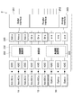
- FIG. 1 is a block diagram illustrating a configuration of an inertial sensor according to an embodiment of the present technology.
- the inertial sensor 1 of the present embodiment is built in, for example, a mobile body such as a vehicle or an aircraft, a portable information terminal such as a smart phone, an electronic device such as a digital camera, a sensor head portion in a motion measuring device, or the like.
- the inertial sensor 1 is configured as an acceleration sensor that detects acceleration in three axial directions that acts on an object (detection target) such as the mobile body, the portable information terminal, the electronic device, or the sensor head.
- the inertial sensor 1 of the present embodiment is configured to be able to extract a dynamic acceleration component and a static acceleration component from the accelerations in the three axis directions.
- the dynamic acceleration component means an AC component of the acceleration, and typically corresponds to a motion acceleration (translation acceleration, centrifugal acceleration, tangential acceleration, etc.) of the object.
- the static acceleration component means a DC component of the acceleration and typically corresponds to gravitational acceleration or acceleration estimated as gravitational acceleration.
- the inertial sensor 1 has a sensor element 10 and a controller 20 (signal processing device).
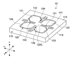
- FIG. 2 is a front perspective view schematically showing the configuration of the sensor element 10.
- the sensor element 10 includes two types of acceleration detection units (a first acceleration detection unit 11 and a second acceleration detection unit) that respectively detect information related to acceleration in the three-axis (x, y, and z-axis) directions in FIG. 12).
- a first acceleration detection unit 11 and a second acceleration detection unit
- the sensor element 10 includes two types of acceleration detection units (a first acceleration detection unit 11 and a second acceleration detection unit) that respectively detect information related to acceleration in the three-axis (x, y, and z-axis) directions in FIG. 12).
- the first acceleration detection unit 11 is, for example, a piezoelectric acceleration sensor, and includes a signal (Acc-AC-x) including information related to acceleration parallel to the x-axis direction as the first detection signal, and the y-axis direction.
- a signal (Acc-AC-y) including information related to acceleration parallel to the axis and a signal (Acc-AC-z) including information related to acceleration parallel to the z-axis direction are output. These signals have an alternating waveform corresponding to the acceleration of each axis.
- the second acceleration detector 12 is a non-piezoelectric acceleration sensor, and a signal (Acc-DC-x), y containing information related to acceleration parallel to the x-axis direction is used as the second detection signal.
- a signal (Acc-DC-y) including information related to acceleration parallel to the axial direction and a signal (Acc-DC-z) including information related to acceleration parallel to the z-axis direction are output. These signals have an output waveform in which an AC component corresponding to the acceleration of each axis is superimposed on the DC component.
- the controller 20 moves from the acceleration in the three-axis direction. It has an acceleration calculation unit 200 that extracts a static acceleration component and a static acceleration component, respectively.
- the controller 20 can be realized by hardware elements used in a computer such as a CPU (Central Processing Unit), a RAM (Random Access Memory), and a ROM (Read Only Memory) and necessary software.
- a CPU Central Processing Unit
- RAM Random Access Memory
- ROM Read Only Memory
- PLD Programmable Logic Device
- FPGA Field Programmable Gate Array
- DSP Digital Signal Processor
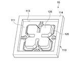
- FIG. 3 is a perspective view of the back surface side of the sensor element 10
- FIG. 4 is a plan view of the front surface side of the sensor element 10.
- the sensor element 10 includes an element body 110, a first acceleration detection unit 11 (first detection elements 11x1, 11x2, 11y1, 11y2), and a second acceleration detection unit 12 (second detection elements 12x1, 12x2, 12y1, 12y2).
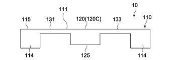
- the element body 110 has a main surface portion 111 parallel to the xy plane and a support portion 114 on the opposite side.
- the element body 110 is typically composed of an SOI (Silicon On On Insulator) substrate, an active layer (silicon substrate) that forms the main surface portion 111, and a frame-shaped support layer (silicon substrate) that forms the support portion 114. It has the laminated structure.
- the main surface portion 111 and the support portion 114 have different thicknesses, and the support portion 114 is formed thicker than the main surface portion 111.
- the element body 110 has a movable plate 120 (movable part) capable of moving under acceleration.
- the movable plate 120 is provided at the center of the main surface portion 111 and is formed by processing the active layer forming the main surface portion 111 into a predetermined shape. More specifically, the movable plate 120 having a plurality of (four in this example) blade portions 121 to 124 having a symmetrical shape with respect to the central portion of the main surface portion 111 is constituted by the plurality of groove portions 112 formed in the main surface portion 111. Is done.
- the peripheral edge portion of the main surface portion 111 constitutes a base portion 115 that faces the support portion 114 in the z-axis direction.
- the support portion 114 is formed in a frame shape having a rectangular recess 113 that opens the back surface of the movable plate 120.
- the support part 114 is configured as a bonding surface bonded to a support substrate (not shown).
- the support substrate may be formed of a circuit board that electrically connects the sensor element 10 and the controller 20, or may be formed of a relay board or a package board that is electrically connected to the circuit board.
- the support portion 114 may be provided with a plurality of external connection terminals that are electrically connected to the circuit board, the relay board, and the like.
- the blade portions 121 to 124 of the movable plate 120 are each formed of a plate piece having a predetermined shape (in this example, a substantially hexagonal shape), and are arranged at intervals of 90 ° around a central axis parallel to the z axis.
- the thickness of each of the blade portions 121 to 124 corresponds to the thickness of the active layer constituting the main surface portion 111.
- the blade portions 121 to 124 are integrally connected to each other at the central portion 120C of the movable plate 120, and are integrally supported so as to be movable relative to the base portion 115.
- the movable plate 120 further includes a weight portion 125 as shown in FIG.
- the weight portion 125 is integrally provided on the back surface of the central portion 120C of the movable plate 120 and the back surfaces of the blade portions 121 to 124.
- the size, thickness, and the like of the weight portion 125 are not particularly limited, and are set to appropriate sizes that can obtain the desired vibration characteristics of the movable plate 120.
- the weight portion 125 is formed, for example, by processing the support layer forming the support portion 114 into a predetermined shape.
- the movable plate 120 is connected to the base portion 115 via a plurality (four in this example) of bridge portions 131 to 134.
- the plurality of bridge portions 131 to 134 are provided between the blade portions 121 to 124, respectively, and are formed by processing the active layer forming the main surface portion 111 into a predetermined shape.
- the bridge portion 131 and the bridge portion 133 are arranged to face each other in the x-axis direction, and the bridge portion 132 and the bridge portion 134 are arranged to face each other in the y-axis direction.
- the bridge portions 131 to 134 constitute a part of the movable portion that can move relative to the base portion 115, and elastically support the central portion 120C of the movable plate 120.
- Each of the bridge portions 131 to 134 has the same configuration, and includes a first beam portion 130a, a second beam portion 130b, and a third beam portion 130c, respectively, as shown in FIG.
- the first beam portion 130a extends linearly from the peripheral edge portion of the central portion 120C of the movable plate 120 in the x-axis direction and the y-axis direction, and is disposed between the blade portions 121 to 124 adjacent to each other.
- the second beam portion 130b extends linearly in the x-axis direction and the y-axis direction, respectively, and connects between the first beam portion 130a and the base portion 115, respectively.
- the third beam portion 130c extends linearly in the directions intersecting the x-axis direction and the y-axis direction, respectively, an intermediate portion between the first beam portion 130a and the second beam portion 130b, a base portion 115, Are connected to each other.
- Each of the bridge portions 131 to 134 includes two third beam portions 130c, and is configured such that two third beam portions 130c sandwich one second beam portion 130b in the xy plane.
- the rigidity of the bridge portions 131 to 134 is set to an appropriate value that can stably support the moving movable plate 120.
- the bridge portions 131 to 134 are set to have appropriate rigidity capable of being deformed by the weight of the movable plate 120, and the magnitude of the deformation can be detected by the second acceleration detecting unit 12 described later. If there is, it will not be specifically limited.
- the movable plate 120 is supported on the base portion 115 of the element main body 110 via the four bridge portions 131 to 134, and the base is provided with the bridge portions 131 to 134 as fulcrums by the inertial force according to the acceleration. It is configured to be movable (movable) relative to the portion 115.
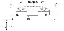
- 5A to 5C are schematic side cross-sectional views for explaining the movement of the movable plate 120, where A is when no acceleration is applied, B is when acceleration is generated along the x-axis direction, and C is z-axis direction. The time of acceleration occurrence along is shown.
- the solid line shows a state when acceleration occurs in the left direction on the paper surface
- the solid line in FIG. 5C shows a state when acceleration occurs in the upward direction on the paper surface.
- the movable plate 120 When no acceleration is generated, the movable plate 120 is maintained in a state parallel to the surface of the base portion 115 as shown in FIGS. 2 and 5A. In this state, for example, when acceleration along the x-axis direction occurs, the movable plate 120 tilts counterclockwise around the bridge portions 132 and 134 extending in the y-axis direction as shown in FIG. 5B. As a result, the bridge portions 131 and 133 facing each other in the x-axis direction receive bending stresses in opposite directions along the z-axis direction.
- the movable plate 120 tilts counterclockwise (or clockwise) about the bridge portions 131 and 133 extending in the x-axis direction, although not shown.
- the bridge portions 132 and 134 facing each other in the axial direction receive bending stresses in opposite directions along the z-axis direction.
- the first acceleration detection unit 11 and the second acceleration detection unit 12 are provided in the bridge portions 131 to 134, respectively.
- the inertial sensor 1 measures the direction and magnitude of acceleration acting on the sensor element 10 by detecting deformation caused by the bending stress of the bridge portions 131 to 134 by the acceleration detection units 11 and 12.
- the first acceleration detection unit 11 includes a plurality (four in this example) of first detection elements 11x1, 11x2, 11y1, and 11y2.
- the detection elements 11x1 and 11x2 are provided on the axial centers of the surfaces of the two bridge portions 131 and 133 that face each other in the x-axis direction, and one detection element 11x1 is provided on the first beam portion 130a in the bridge portion 131.
- the other detection element 11x2 is disposed on the first beam portion 130a of the bridge portion 133, respectively.
- the detection elements 11y1 and 11y2 are provided on the axial centers of the surfaces of the two bridge portions 132 and 134 that face each other in the y-axis direction, and one detection element 11y1 is the first in the bridge portion 132.
- the other detection element 11y2 is arranged on the first beam portion 130a of the bridge portion 134 in the beam portion 130a.
- the first detection elements 11x1 to 11y2 have the same configuration.
- the first detection elements 11x1 to 11y2 are formed of rectangular piezoelectric detection elements having long sides in the axial direction of the first beam portion 130a.
- the first detection elements 11x1 to 11y2 are each composed of a laminate of a lower electrode layer, a piezoelectric film, and an upper electrode layer.
- the piezoelectric film is typically made of lead zirconate titanate (PZT), but is not limited to this.
- the piezoelectric film generates a potential difference between the upper electrode layer and the lower electrode layer according to the bending deformation amount (stress) in the z-axis direction of the first beam portion 130a (piezoelectric effect).
- the upper electrode layers are electrically connected to the relay terminals 140 provided on the surface of the base portion 115 via wiring layers (not shown) formed on the bridge portions 131 to 134, respectively.
- the relay terminal 140 may be configured as an external connection terminal electrically connected to the support substrate. For example, the other end of a bonding wire whose one end is connected to the support substrate is connected.
- the lower electrode layer is typically connected to a reference potential such as a ground potential.
- the first acceleration detection unit 11 configured as described above outputs only when there is a stress change due to the characteristics of the piezoelectric film, and does not output when the stress value is not changed even if stress is applied. Therefore, the magnitude of dynamic acceleration (motion acceleration) acting on the movable plate 120 is mainly detected. Therefore, the output (first detection signal) of the first acceleration detector 11 mainly includes an output signal having an AC waveform that is a dynamic component (AC component) corresponding to the motion acceleration.
- AC component dynamic component
- the second acceleration detection unit 12 includes a plurality (four in this example) of second detection elements 12x1, 12x2, 12y1, and 12y2.
- the detection elements 12x1 and 12x2 are provided on the axial centers of the surfaces of the two bridge portions 131 and 133 that face each other in the x-axis direction, and one detection element 12x1 is provided on the second beam portion 130b in the bridge portion 131.
- the other detection element 12x2 is disposed on the second beam portion 130b of the bridge portion 133, respectively.
- the detection elements 12y1 and 12y2 are provided on the axial centers of the surfaces of the two bridge portions 132 and 134 facing each other in the y-axis direction, and one detection element 12y1 is the second in the bridge portion 132.
- the other detection element 12y2 is arranged on the second beam portion 130b of the bridge portion 134 in the beam portion 130b.
- the second detection elements 12x1 to 12y2 have the same configuration.
- the second detection elements 12x1 to 12y2 are configured by piezoresistive detection elements having long sides in the axial direction of the second beam portion 130b.
- the second detection elements 12x1 to 12y2 each include a resistance layer and a pair of terminal portions connected to both ends in the axial direction.
- the resistance layer is, for example, a conductor layer formed by doping an impurity element on the surface (silicon layer) of the second beam portion 130b, and the amount of bending deformation of the second beam portion 130b in the z-axis direction ( A resistance change corresponding to the stress is generated between the pair of terminal portions (piezoresistance effect).
- the pair of terminal portions are electrically connected to the relay terminals 140 provided on the surface of the base portion 115 via wiring layers (not shown) formed on the bridge portions 131 to 134, respectively.
- the second acceleration detector 12 configured as described above determines not only the dynamic acceleration (motion acceleration) acting on the movable plate 120 because the resistance value is determined by the absolute stress value due to the characteristics of the piezoresistance.
- the static acceleration (gravity acceleration) acting on the movable plate 120 is also detected. Therefore, in the output (second detection signal) of the second acceleration detector 11, the dynamic component (AC component) corresponding to the motion acceleration is superimposed on the gravitational acceleration or a static component (DC component) corresponding thereto. Has an output waveform.
- the second detection elements 12x1 to 12y2 are not limited to the example configured with the piezoresistive type detection elements, and other non-piezoelectric detection elements that can detect the acceleration of the DC component, such as an electrostatic type. It may be constituted by.
- the electrostatic type the movable electrode portion and the fixed electrode portion constituting the electrode pair are arranged to face each other in the axial direction of the second beam portion 130b, and according to the amount of bending deformation of the second beam portion 130b. It is comprised so that the opposing distance between both electrode parts may change.
- the first acceleration detector 11 detects acceleration detection signals (Acc-AC-x, Acc-AC-) in the x-axis direction, the y-axis direction, and the z-axis direction based on the outputs of the first detection elements 11x1 to 11y2.
- y, Acc-AC-z are output to the controller 20 (see FIG. 1).
- the acceleration detection signal (Acc-AC-x) in the x-axis direction corresponds to a difference signal (ax1-ax2) between the output (ax1) of the detection element 11x1 and the output (ax2) of the detection element 11x2.
- the acceleration detection signal (Acc-AC-y) in the y-axis direction corresponds to a difference signal (ay1-ay2) between the output (ay1) of the detection element 11y1 and the output (ay2) of the detection element 11y2.
- the acceleration detection signal (Acc-AC-z) in the z-axis direction corresponds to the total sum (ax1 + ax2 + ay1 + ay2) of the detection elements 11x1 to 11y2.
- the second acceleration detector 12 detects acceleration detection signals (Acc-DC-x, Acc) in the x-axis direction, the y-axis direction, and the z-axis direction based on the outputs of the second detection elements 12x1 to 12y2.
- -DC-y, Acc-DC-z are output to the controller 20 (see FIG. 1).
- the acceleration detection signal (Acc-DC-x) in the x-axis direction corresponds to a difference signal (bx1-bx2) between the output (bx1) of the detection element 12x1 and the output (bx2) of the detection element 12x2.
- the acceleration detection signal (Acc-DC-y) in the y-axis direction corresponds to a difference signal (by1-by2) between the output (by1) of the detection element 12y1 and the output (by2) of the detection element 12y2.
- the acceleration detection signal (Acc-DC-z) in the z-axis direction corresponds to the sum (bx1 + bx2 + by1 + by2) of the outputs of the detection elements 12x1 to 12y2.
- the calculation processing of the acceleration detection signals in the respective axis directions may be executed before the controller 20 or may be executed by the controller 20.
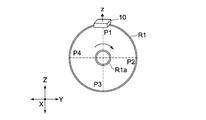
- FIG. 6A the output waveform at the z-direction detection axis of the sensor element 10 (first and second acceleration detectors 11 and 12) attached to the peripheral surface of the rotating body R1 that rotates at a constant rotational speed.
- FIG. 6B An example is shown in FIG. 6B.
- the rotation radius of the rotating body R1 is set to be small so that the centrifugal force of the sensor element 10 can be ignored (the same applies to FIGS. 7A, 8A, and 9A).
- the X, Y, and Z axes represent three orthogonal directions in real space (the Z axis is the vertical direction) (the same applies to FIGS. 7A, 8A, and 9A), and in FIG. 6B, the horizontal axis represents phase or time.
- the vertical axis represents the magnitude of acceleration in the z-axis direction (the same applies to FIGS. 7B, 8B, 9B, 10A, and 10B).
- Rotating body R1 has a rotation axis R1a parallel to the horizontal direction.
- the sensor element 10 is attached to the circumferential surface of the rotator R1 so that the z-direction detection axis thereof faces the radial direction of the rotator R1.
- the upward direction in the figure is set as the direction of gravity (see FIG. 6A).
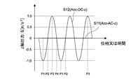
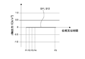
- FIG. 6B shows a detection signal S11 output from the first acceleration detection unit 11 and a second acceleration detection unit 12 when the rotating body R1 is rotated clockwise at a constant rotational speed in the drawing.
- the time change of detection signal S12 is shown, respectively.
- the magnitude of gravitational acceleration acting on the z-axis of the sensor element 10 changes periodically.
- the sensor element 10 rotates at a constant speed around the X axis, a time change of the motion acceleration (dynamic acceleration) applied to the sensor element 10 does not occur. Therefore, since the first acceleration detection unit 11 configured by the piezoelectric detection element is hardly affected by gravity regardless of the rotation position, the detection signal S11 (Acc-AC-z) is flat (constant). Become.
- the detection signals (Acc-AC-x, Acc-AC-y) on the x-direction detection axis and the y-direction detection axis are also zero.
- the second acceleration detection unit 12 composed of a piezoresistive detection element changes in output magnitude according to the rotational position of the sensor element 10 (positions P1 to P4 in FIG. 6A).
- the output is maximized when the z-direction detection axis is parallel to the Z-axis (P1, P3), and the output is zero when the z-direction detection axis is perpendicular to the Z-axis (P2, P4). Therefore, the detection signal S12 (Acc-DC-z) detects a static acceleration of 2G width (-1G to + 1G) with respect to the rotational motion.
- the output of detection signals (Acc-DC-x, Acc-DC-y) on the x-direction detection axis and the y-direction detection axis is orthogonal to the direction of gravity, so in principle anyway Is also zero.
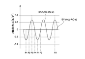
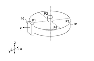
- FIG. 7B shows an example of an output waveform on the z-direction detection axis of the sensor element 10 when the rotation axis of the rotator R1 is inclined obliquely (for example, 45 °) with respect to the horizontal axis as shown in FIG. 7A.
- the detection signal S11 (Acc-AC-z) of the first acceleration detector 11 is zero as in the case 1.
- the detection signal S12 (Acc-DC-z) of the second acceleration detector 12 the z-direction detection axis of the sensor element 10 is inclined 45 ° with respect to the vertical direction (Z-axis direction).
- the maximum value of the output is smaller than that of Case 1, and a static acceleration of ⁇ 2G width ( ⁇ 2G / 2 to + ⁇ 2G / 2) is detected with respect to the rotational motion.
- the gravitational acceleration corresponding to the rotational position is detected on the x direction detection axis or the y direction detection axis.
- FIG. 9A the z direction of the sensor element 10 (first and second acceleration detection units 11 and 12) mounted on the vibration table R2 having the vibration unit R2a extending and contracting in the X-axis direction.
- FIG. 9B An example of the output waveform on the detection axis is shown in FIG. 9B.
- the sensor element 10 is attached to the upper surface parallel to the XY plane of the vibrating body R2 so that the z-direction detection axis faces upward.
- the upward direction in the figure is set as the direction of gravity (see FIG. 9A).
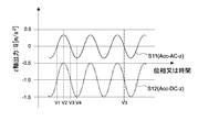
- FIG. 9B shows the time change of the detection signal S11 output from the first acceleration detection unit 11 and the detection signal S12 output from the second acceleration detection unit 12 when the vibration table R2 is vibrated in the vertical direction.
- the excitation frequency of the vibration table R2 is set to an appropriate frequency (for example, 1 Hz) at which the piezoelectric first acceleration detector 11 can detect acceleration.
- the magnitude of the weight acceleration acting on the z-axis of the sensor element 10 changes periodically with the vibration of the vibration table R2.
- the piezoelectric first acceleration detecting unit 11 changes the magnitude of the output in accordance with the vibration position of the vibration table (positions V1 to V4 in FIG. 9A), and the upper dead center (V2) of the vibration table R2 and the upper position.
- the output becomes maximum at the dead point (V4), and the detection signal S11 (Acc-AC-z) detects dynamic acceleration having a 1 G width ( ⁇ 0.5 G to 0.5 G) in the illustrated example. That is, the first acceleration detector 11 outputs a detection signal S11 having an AC waveform corresponding to the vibration acceleration.
- the second acceleration detection unit 12 composed of a piezoresistive detection element also changes its output magnitude according to the vibration position of the vibration table, and the bottom dead center (V2) of the vibration table R2. And the output becomes the maximum at the top dead center (V4).
- the detection signal S12 (Acc-DC-z) has a 1 G width ( ⁇ 1. 5G to -0.5G) is detected (see FIGS. 6B and 9B). That is, the second acceleration detector 12 outputs a detection signal S12 having an output waveform in which an AC component corresponding to vibration acceleration is superimposed on a DC component (-1G in this example).
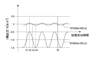
- FIGS. 10A and 10B show output waveforms of the sensor element 10 when the excitation frequency of the vibration table R2 is made smaller than that of the case 4, respectively.
- FIG. 10A shows an example when the excitation frequency is 0.05 Hz
- FIG. 10B shows an example when the excitation frequency is 0.01 Hz.
- the output of the detection signal S11 (Acc-AC-z) of the first acceleration detector 11 decreases as the excitation frequency decreases.
- the piezoelectric element constituting the first acceleration detection unit 11 functions as a high-pass filter having a cutoff frequency near a predetermined frequency (here, for example, 0.5 Hz) as described later, and below the cutoff frequency.
- the detection sensitivity of acceleration in the frequency band tends to be lower than the detection sensitivity of acceleration in the frequency band higher than the cutoff frequency.
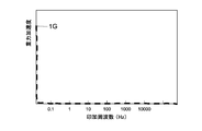
- FIG. 10A shows a case where the sensitivity is about 70%
- FIG. 10B shows a case where the sensitivity is about 10%.
- the second acceleration detection unit 12 composed of a piezoresistive element has a narrow dynamic range compared to the first acceleration detection unit 11 composed of a piezoelectric element. There is an aspect that it is not suitable for detecting a large motion with high accuracy.
- the piezoelectric first acceleration detection unit 11 can detect the net motion acceleration (AC component) without being affected by the static acceleration component (DC component) such as the gravitational acceleration. , It has a characteristic that sensitivity in a predetermined low frequency band is lowered.
- the second acceleration detection unit 12 of the piezoresistive type has an output waveform in which the motion acceleration to be detected is superimposed on the gravity component, so that it is difficult to separate from the gravity acceleration, but it is constant even in the low frequency band. The output sensitivity is obtained.
- the inertial sensor 1 of the present embodiment has a controller 20 that can extract a dynamic acceleration component and a static acceleration component from acceleration acting on the sensor element 10 based on these two detection signals S11 and S12.
- a controller 20 that can extract a dynamic acceleration component and a static acceleration component from acceleration acting on the sensor element 10 based on these two detection signals S11 and S12.
- the controller 20 is electrically connected to the sensor element 10.
- the controller 20 may be mounted inside the device in common with the sensor element 10 or may be mounted on an external device different from the above device. In the former case, the controller 20 may be mounted on a circuit board on which the sensor element 10 is mounted, for example, or mounted on a board different from the circuit board via a wiring cable or the like. In the latter case, the controller 20 is configured to be able to communicate with the sensor element 10 wirelessly or in a wired manner, for example.
- the controller 20 includes an acceleration calculation unit 200, a serial interface 201, a parallel interface 202, and an analog interface 203.
- the controller 20 is electrically connected to control units of various devices that receive the output of the inertial sensor 1.
- the acceleration calculation unit 200 generates dynamic acceleration components (Acc-x, Acc-y, Acc) based on the acceleration detection signals in the respective axial directions output from the first acceleration detection unit 11 and the second acceleration detection unit 12. -z) and static acceleration components (Gr-x, Gr-y, Gr-z) are extracted, respectively.
- the acceleration calculation unit 200 is realized by loading a program recorded in a ROM, which is an example of a non-transitory computer-readable recording medium, into a RAM or the like and executing it by the CPU.
- the serial interface 201 is configured so that the dynamic and static acceleration components of each axis generated in the acceleration calculation unit 200 can be sequentially output to the control unit.
- the parallel interface 202 is configured to be able to output the dynamic and static acceleration components of each axis generated in the acceleration calculation unit 200 to the control unit in parallel.
- the controller 20 may be provided with at least one of the serial interface 201 and the parallel interface 202, or may be selectively switched according to a command from the control unit.
- the analog interface 203 is configured to be able to output the outputs of the first and second acceleration detectors 11 and 12 to the control unit as they are, but may be omitted as necessary.
- reference numeral 204 denotes a converter 201 that performs AD (Analog-Digital) conversion on the acceleration detection signals of the respective axes.
- FIG. 11 is a circuit diagram showing a configuration example of the acceleration calculation unit 200.
- the acceleration calculation unit 200 includes a gain adjustment circuit 21, a sign inversion circuit 22, an addition circuit 23, and a correction circuit 24. These circuits 21 to 24 have a common configuration for each of the x, y, and z axes, and by performing a common calculation process on each axis, the dynamic acceleration component (motion acceleration) of each axis and A static acceleration component (gravity acceleration) is extracted.
- FIG. 12 shows a processing block for extracting a static acceleration component from the acceleration detection signal in the x-axis direction.
- the gain adjustment circuit 21 includes a first acceleration detection signal (Acc-AC-x) regarding the x-axis direction output from the first acceleration detection unit 11 (11x1, 11x2), and a second acceleration detection unit 12 (12x1). , 12x2), the gain of each signal is adjusted so that the second acceleration detection signal (Acc-DC-x) in the x-axis direction outputted from 12x2) has the same level.
- the gain adjustment circuit 21 includes an amplifier that amplifies the output (Acc-AC-x) of the first acceleration detection unit 11 and the output (Acc-DC-x) of the second acceleration detection unit 12.
- the output sensitivity and dynamic range of an acceleration sensor differ depending on the detection method.
- a piezoelectric acceleration sensor is more sensitive than a non-piezoelectric (piezoresistive, electrostatic) acceleration sensor.
- the first acceleration detector 11 corresponds to a piezoelectric acceleration sensor
- the second acceleration detector 12 corresponds to a piezoresistive acceleration sensor.
- the gain adjustment circuit 21 sets the outputs (first and second acceleration detection signals) of the acceleration detection units 11 and 12 to N times and M so that the outputs of the acceleration detection units 11 and 12 are at the same level. Amplify twice.
- the amplification factors N and M are positive numbers and satisfy the relationship N ⁇ M.
- the values of the amplification factors N and M are not particularly limited, and may be set as coefficients that also serve as temperature compensation for the acceleration detection units 11 and 12 depending on the use environment (use temperature) of the inertial sensor 1.
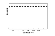
- FIG. 14 is an example of output characteristics of the first acceleration detection signal and the second acceleration detection signal, and shows a comparison between the output characteristics before gain adjustment and the output characteristics after gain adjustment.
- the horizontal axis represents the frequency of acceleration acting on the inertial sensor 1
- the vertical axis represents output (sensitivity) (the same applies to FIGS. 15 to 19).
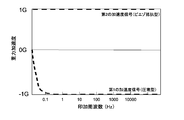
- the output sensitivity of the acceleration component in the low frequency region below 0.5 Hz is the acceleration component in the higher frequency region.
- the output sensitivity is substantially 0 particularly in a stationary state (motion acceleration is 0).
- the second acceleration detection signal (Acc-DC-x) of the piezoresistive method has a constant output sensitivity in the entire frequency range, so that the acceleration component in a stationary state (that is, the static acceleration component) is also constant.
- the output sensitivity can be detected. Therefore, the gain adjustment circuit 21 amplifies the first acceleration detection signal and the second acceleration detection signal at a predetermined magnification such that the first acceleration detection signal and the second acceleration detection signal have the same output level. Can be extracted.
- the sign inverting circuit 22 and the adder circuit 23 are configured to detect acceleration in each axial direction based on a difference signal between the first acceleration detection signal (Acc-AC-x) and the second acceleration detection signal (Acc-DC-x).
- a differential operation circuit that extracts a static acceleration component (DC component) from the above is configured.
- the sign inversion circuit 22 has an inverting amplifier (amplification factor: ⁇ 1) for inverting the sign of the first acceleration detection signal (Acc-AC-x) after gain adjustment.
- FIG. 15 shows an example of output characteristics of the first acceleration detection signal (Acc-AC-x) after sign inversion.
- the second acceleration detection signal (Acc-DC-x) is output to the subsequent addition circuit 23 without its sign being inverted.
- the sign inversion circuit 22 may be configured in common with the gain adjustment circuit 21 in the preceding stage.
- the adder circuit 23 adds the first acceleration detection signal (Acc-AC-x) and the second acceleration detection signal (Acc-DC-x) output from the sign inversion circuit 22 to obtain a static acceleration component. Is output.
- FIG. 16 shows an example of output characteristics of the adder circuit 23. Since the first and second acceleration detection signals (outputs) are adjusted to the same level in the gain adjustment circuit 21, the net static acceleration component (Gr-x) is extracted by obtaining these difference signals. Will be.
- This static acceleration component typically corresponds to a gravitational acceleration component or an acceleration component including gravitational acceleration.
- the piezoelectric detection type first acceleration detection unit 11 has a low detection sensitivity in the vicinity of a low frequency, and the generation of other axis sensitivity causes an axis direction other than the target axis (here, the y axis direction and the z axis For example, the acceleration component in the direction) inevitably overlaps, so that the dynamic acceleration component in the frequency domain indicated by hatching in FIG.
- the present embodiment includes a correction circuit 24 for canceling the error based on the output of the adder circuit 23.
- the correction circuit 24 includes a triaxial composite value calculation unit 241 and a low frequency sensitivity correction unit 242.
- the correction circuit 24 calculates a correction coefficient ⁇ based on the output of the addition circuit 23 (difference signal between the first and second acceleration detection signals), and uses the correction coefficient ⁇ to generate the first acceleration detection signal (Acc ⁇ AC-x).
- the 3-axis composite value calculation unit 241 is provided in common for processing blocks that extract all static acceleration components in the x-axis, y-axis, and z-axis directions, and outputs (first and second) of the adder circuit 23 for each axis.
- the correction coefficient ⁇ is calculated using the total value of the difference signal of the acceleration detection signal.
- the values of the static acceleration components (Gr-x, Gr-y, Gr-z) in each of the three axial directions vary depending on the attitude of the sensor element 10, and from moment to moment according to changes in the attitude of the sensor element 10. Change. For example, when the z-axis direction of the sensor element 10 coincides with the gravity direction (vertical direction), the z-axis direction is greater than the static acceleration components (Gr-x, Gr-y) in the x-axis direction and the y-axis direction.
- the static acceleration component of (Gr-z) shows a large value. Thus, it is possible to estimate the gravitational direction of the sensor element 10 at that time from the values of the static acceleration components (Gr-x, Gr-y, Gr-z) in the three axial directions.
- the low-frequency sensitivity correction unit 242 includes a multiplier that multiplies the first acceleration detection signal (Acc-AC-x) whose sign is inverted by the correction coefficient ⁇ .
- the first acceleration detection signal is input to the adder circuit 23 in a state where the low-frequency sensitivity error is attenuated. Therefore, the adder circuit 23 outputs an acceleration signal having a frequency characteristic as shown in FIG. As described above, as a result of outputting only the static acceleration component corresponding to the gravitational acceleration, the accuracy of extracting the gravitational acceleration component is improved.
- the correction circuit 24 is configured to execute a process of multiplying the first acceleration detection signal by the correction coefficient ⁇ when calculating the static acceleration component.
- a process of multiplying the detection signal (Acc-DC-x) by the correction coefficient ⁇ may be executed, or the acceleration detection signal to be corrected is the first acceleration detection signal according to the magnitude of the acceleration change.
- the second acceleration detection signal may be switched.
- the correction circuit 24 corrects the first acceleration detection signal using the correction coefficient ⁇ when the acceleration change of one of the first acceleration detection signal and the second acceleration detection signal is greater than or equal to a predetermined value. Composed. The greater the change in acceleration (the higher the applied frequency), the higher the rate at which the error component leaks into the first acceleration detection signal, so that the error component can be efficiently reduced. This configuration is particularly effective when the motion acceleration is relatively large, such as in motion analysis applications.
- the correction circuit 24 corrects the second acceleration detection signal using the correction coefficient ⁇ when the change in acceleration of one of the first acceleration detection signal and the second acceleration detection signal is equal to or less than a predetermined value.
- a predetermined value Configured as follows. The smaller the acceleration change (the lower the applied frequency), the higher the rate at which the error component leaks into the second acceleration detection signal, so that the error component can be efficiently reduced. This configuration is particularly effective when the motion acceleration is relatively small, such as a leveling operation of a digital camera.
- the static acceleration component in each axial direction is extracted as described above, and the dynamic acceleration components (Acc-x, Acc-y, Acc-z) in each axial direction are extracted as shown in FIG.
- the first acceleration detection signal (Acc-AC-x, Acc-AC-y, Acc-AC-z) whose gain is adjusted in the gain adjustment circuit 21 is referred to.
- the first acceleration detection signal may be used as it is for extracting the dynamic acceleration component.
- a part of the dynamic acceleration component may leak into the static acceleration component.
- the acceleration component is reduced, making it difficult to detect with high accuracy. Therefore, by correcting the first acceleration detection signal using the correction coefficient ⁇ calculated by the correction circuit 24, it is possible to improve the detection accuracy of the dynamic acceleration component.
- the correction circuit 24 uses the reciprocal (1 / ⁇ ) of the correction coefficient ⁇ acquired by the triaxial composite value calculation unit 241 as the first acceleration.
- a multiplier for multiplying the signals (Acc-AC-x, Acc-AC-y, Acc-AC-z) is included.
- the low-frequency sensitivity component of the first acceleration signal is compensated, so that the extraction accuracy of the dynamic acceleration components (Acc-x, Acc-y, Acc-z) is improved.
- FIG. 18 schematically shows the output characteristics of the dynamic acceleration component.
- the correction circuit 24 is configured to execute a process of multiplying the first acceleration detection signal by the reciprocal (1 / ⁇ ) of the correction coefficient when calculating the dynamic acceleration component.
- the second acceleration detection signal (Acc-DC-x, Acc-DC-y, Acc-DC-z) may be configured to execute a process of multiplying the inverse of the correction coefficient (1 / ⁇ ).
- the acceleration detection signal to be corrected is switched between the first acceleration detection signal and the second acceleration detection signal in accordance with the magnitude of the acceleration change. May be.
- the dynamic acceleration component and static acceleration component correction processing by the low-frequency sensitivity correction unit 242 is performed when the composite value calculated by the triaxial composite value calculation unit 241 is other than 1G (G: gravitational acceleration). It is considered effective.
- G gravitational acceleration
- combination value becomes less than 1G the case where the sensor element 10 is falling freely is mentioned, for example.
- the first acceleration detection signal detected by the piezoelectric method has a high-pass filter (HPF) output characteristic, and an output below the cutoff frequency is output to the output of the adder circuit 23 as an error component of low-frequency sensitivity. It remains (see FIG. 16).
- the error component is attenuated by an arithmetic method using the correction circuit 24.
- the cut-off frequency is lower in order to improve the accuracy of canceling the error component.
- a piezoelectric body having a relatively large capacitance and internal resistance may be used as the piezoelectric film of the detection elements (11x1, 11x2, 11y1, and 11y2) constituting the first acceleration detection unit 11.
- the cut-off frequency of the low-frequency sensitivity can be lowered to around 0 Hz as much as possible, so that the error component of the low-frequency sensitivity can be minimized.
- the movable plate 120 moves with respect to the base portion 115 in the manner shown in FIGS. 5A to 5C according to the direction of acceleration.
- the first acceleration detection unit 11 detection elements 11x1, 11x2, 11y1, 11y2
- the second acceleration detection unit 12 detection elements 12x1, 12x2, 12y1, 12y2
- a corresponding detection signal is output to the controller 20.
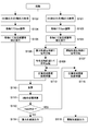
- FIG. 20 is a flowchart illustrating an example of a processing procedure of an acceleration detection signal in the controller 20 (acceleration calculation unit 200).
- the controller 20 acquires the first acceleration detection signal (Acc-AC-x, Acc-AC-y, Acc-AC-z) of each axis from the first acceleration detection unit 11 at a predetermined sampling interval.
- the second acceleration detection unit 12 receives (acquires) second acceleration detection signals (Acc-DC-x, Acc-DC-y, Acc-DC-z) for each axis (steps 101 and 102). .
- the detection signals may be acquired simultaneously (in parallel) or sequentially (in series).
- the controller 20 adjusts the gain of each detection signal in the gain adjustment circuit 21 so that the first and second acceleration detection signals have the same level for each axis (FIG. 14, steps 103 and 104). If necessary, correction for the purpose of temperature compensation of the first and second acceleration detection signals is performed for each axis (steps 105 and 106).
- the controller 20 uses the first acceleration detection signal (Acc-AC-x, Acc-AC-y, Acc-AC-z) for each axis as a dynamic acceleration calculation system (motion acceleration system) and static acceleration. Branches to the calculation system (gravity acceleration system), respectively (steps 107 and 108).
- the first acceleration detection signal branched to the static acceleration calculation system is input to the addition circuit 23 after the sign is inverted in the sign inversion circuit 22 (step 109 in FIG. 15).
- the controller 20 adds the first acceleration detection signal (Acc-AC-x, Acc-AC-y, Acc-AC-z) whose sign is inverted and the second acceleration detection signal for each axis in the adding circuit 23. (Acc-DC-x, Acc-DC-y, Acc-DC-z) are added to calculate the static acceleration components (Gr-x, Gr-y, Gr-z) (FIG. 16, step 110). ). Further, the controller 20 calculates the three-axis combined value of these static acceleration components in the three-axis combined value calculation unit 241 (step 111). If the value is other than 1G, the low-frequency sensitivity correction unit 242 calculates the combined value.
- the controller 20 outputs the calculated gravitational acceleration component (static acceleration component) to the outside (step 114). Note that the present invention is not limited thereto, and the calculated gravitational acceleration component (static acceleration component) may be output to the outside every time the composite value is calculated.
- the controller 20 uses the first acceleration detection signal (Acc-AC-x, Acc) obtained by branching the reciprocal (1 / ⁇ ) of the calculated correction coefficient ⁇ to the motion acceleration system. -AC-y, Acc-AC-z) is executed (steps 112 and 115).
- the controller 20 outputs the calculated motion acceleration component (dynamic acceleration component) to the outside (step 116). Note that the present invention is not limited thereto, and the calculated motion acceleration component (dynamic acceleration component) may be output to the outside each time the composite value is calculated.
- the inertial sensor 1 of the present embodiment uses the difference between the detection methods of the first and second acceleration detectors 11 and 12 to obtain the dynamic acceleration component and the static acceleration component from these outputs. Configured to extract. Thereby, the motion acceleration which acts on an object (detection object, such as an electronic device) can be accurately measured.
- the gravitational acceleration component can be accurately extracted from the output of the inertial sensor 1, the posture of the detection target with respect to the direction of gravity can be detected with high accuracy. Thereby, for example, a horizontal posture of a detection target such as a flying object can be stably maintained.
- a piezoelectric acceleration sensor is employed for the first acceleration detector 11, and a non-piezoelectric (piezoresistive or electrostatic capacitance) acceleration sensor is used as the second acceleration detector 12. Therefore, an inertial sensor having a wide dynamic range and high sensitivity in a low frequency region can be obtained.
- FIG. 21 is a block diagram illustrating a configuration of an inertial sensor according to the second embodiment of the present technology.
- the configuration different from the first embodiment will be mainly described, and the same configuration as the first embodiment will be denoted by the same reference numeral, and the description thereof will be omitted or simplified.
- the inertial sensor 2 of the present embodiment includes a first and second acceleration detectors 11 and 12 and a three-axis angular velocity detection signal (first 3 detection signal) and a controller 220.
- the controller 220 is different from the first embodiment in that in addition to the acceleration calculation unit 200, the controller 220 includes an angular velocity calculation unit 300 that calculates the angular velocities around the three axes based on the triaxial angular velocity detection signal.
- the angular velocity detection unit 30 may be configured by a single sensor element integrated with three axes capable of detecting angular velocities around three axes, or may be configured by combining a plurality of sensor elements integrated with a single axis or two axes. Also good.
- the angular velocity calculation unit 300 generates angular velocity signals ( ⁇ -x, ⁇ -y, ⁇ -z) around three axes based on angular velocity detection signals (Gyro-x, Gyro-y, Gyro-z) around three axes. Each is calculated and output to the outside via the serial interface 201, the parallel interface 202, or the analog interface 203.
- the angular velocity calculation unit 300 may be configured separately from the acceleration calculation unit 200 or may be configured by a calculation unit 230 common to the acceleration calculation unit 200.
- the rotation radius and the rotation center of the detection target can be calculated by combining the motion acceleration information calculated by the acceleration calculation unit 200 and the angular velocity information calculated by the angular velocity calculation unit 300 (see Japanese Patent No. 5407863). ).
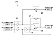
- FIG. 22 is a circuit diagram illustrating a configuration example of the acceleration calculation unit 210 according to the present embodiment.
- the processing blocks for the x-axis direction are shown, but the processing blocks for the y-axis direction and the z-axis direction are also composed of similar circuits, although not shown.
- the acceleration calculation unit 210 of the present embodiment includes a gain adjustment circuit 21, a low-pass filter 25, a first subtractor 26, a second subtractor 27, and an adder 28.
- the acceleration calculation unit 210 is configured to cancel an error component of low frequency sensitivity by each axis alone.
- the gain adjustment circuit 21 is configured so that the first acceleration detection signal (Acc-AC-x) and the second acceleration detection signal (Acc-DC-x) are at the same level. The gain of each signal is adjusted (see FIG. 14).
- the low-pass filter 25 is set to a cut-off frequency that allows an acceleration component of 0.1 Hz or less to pass through, for example.
- the cut-off frequency of the low-pass filter 25 is typically set to a cut-off frequency of the piezoelectric element constituting the first acceleration detection unit 11 or a frequency lower than this.
- the low-pass filter 25 outputs a low-frequency component including a DC component such as gravitational acceleration in the second acceleration detection signal (Acc-DC-x) whose gain has been adjusted.
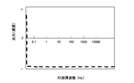
- An example of the output signal of the low-pass filter 25 is schematically shown in FIG.
- a DC component such as gravitational acceleration in the second acceleration detection signal (Acc-DC-x)
- the first subtractor 26 calculates a difference between the gain-adjusted first detection signal (Acc-AC-x) and the output signal of the low-pass filter 25.
- the polarity of the first detection signal is inverted and added to the output of the low-pass filter 25.
- an acceleration signal having output characteristics as schematically shown in FIG. 24 is obtained.
- the first subtractor 26 converts the acceleration signal obtained by the difference calculation into a signal from which the polarity is removed as shown in FIG. 25, and outputs this as a static acceleration component (Gr-x). This signal corresponds to the net gravitational acceleration component detected on the x direction detection axis of the sensor element.
- the second subtractor 27 calculates a difference between the output signal of the low-pass filter 25 and the output signal of the first subtractor 26. Thereby, as schematically shown in FIG. 26, an output characteristic in which the net gravitational acceleration component is removed from the second acceleration detection signal (Acc-DC-x) that has passed through the low-pass filter 25 is obtained.
- the adder 28 adds the gain-adjusted first acceleration detection signal (Acc-AC-x) and the output signal of the second subtractor 27. Thereby, an acceleration signal having output characteristics as schematically shown in FIG. 27 is obtained. That is, the adder 28 outputs, as a dynamic acceleration component (Acc_x), a signal obtained by correcting the low frequency region of the first acceleration detection signal (Acc-AC-x) with the output of the second subtractor 27. This signal corresponds to the net motion acceleration component detected on the x-direction detection axis of the sensor element.
- the low frequency sensitivity of the dynamic acceleration component and the static acceleration component can be corrected by each axis alone, so that the circuit configuration can be simplified or the calculation load can be reduced. .
- the sensor element 10 shown in FIGS. 2 to 4 is used as the sensor element.
- the configuration is not particularly limited as long as the acceleration in the triaxial direction can be detected.
- the dynamic acceleration component and the static acceleration component are extracted using both the piezoelectric first acceleration detection unit 11 and the non-piezoelectric second acceleration detection unit 12.
- the acceleration detection units 11 and 12 may be used separately to acquire the dynamic acceleration component or the static acceleration component.
- the static acceleration component is calculated based on the detection signal of the non-piezoelectric second acceleration detection unit
- the dynamic acceleration component is calculated using the piezoelectric first You may calculate based on the detection signal of an acceleration detection part.
- this technique can also take the following structures.
- (1) including at least information related to acceleration along one axial direction, including a first detection signal having an AC waveform corresponding to the acceleration, information related to the acceleration, and an AC component corresponding to the acceleration.
- a signal processing apparatus comprising: an acceleration calculation unit that extracts a dynamic acceleration component and a static acceleration component from the acceleration based on a second detection signal having an output waveform superimposed on a DC component.
- the first detection signal and the second detection signal further include information related to acceleration in a multiaxial direction including the uniaxial direction, The acceleration processing unit extracts a dynamic acceleration component and a static acceleration component for each of the multi-axis directions.
- the said acceleration calculating part has a calculating circuit which extracts the said static acceleration component from the said acceleration based on the difference signal of a said 1st detection signal and a said 2nd detection signal.
- Signal processing apparatus (4) The signal processing device according to (3) above, The acceleration processing unit further includes a gain adjustment circuit that adjusts a gain of each signal so that the first detection signal and the second detection signal have the same level.
- the acceleration calculation unit further includes a correction circuit that calculates a correction coefficient based on the difference signal and corrects one of the first detection signal and the second detection signal using the correction coefficient. Processing equipment.
- the correction circuit corrects the first detection signal using the correction coefficient when a change in acceleration of one of the first detection signal and the second detection signal is greater than or equal to a predetermined value.
- apparatus. The signal processing device according to (5) or (6) above, The correction circuit corrects the second detection signal using the correction coefficient when a change in acceleration of one of the first detection signal and the second detection signal is equal to or less than a predetermined value.
- apparatus. (8) The signal processing device according to any one of (2) to (7) above, The acceleration calculation unit further includes a low-frequency sensitivity correction unit that corrects the dynamic acceleration component and the static acceleration component using a composite value of the difference signal calculated for each of the multi-axis directions.
- the arithmetic circuit is: A low-pass filter for passing a low-frequency component including the DC component from the second detection signal; A signal processing apparatus, comprising: a first subtractor that calculates a difference between the first detection signal and the output signal of the low-pass filter.
- the arithmetic circuit includes a second subtractor for calculating a difference between the output signal of the low-pass filter and the output signal of the first subtractor; An adder that adds the first detection signal and the output signal of the second subtractor.
- the signal processing device sequentially outputs the dynamic acceleration component and the static acceleration component.
- a signal processing device further comprising: an angular velocity calculation unit that calculates angular velocities around the multi-axis based on a third detection signal including information related to angular velocities around the multi-axis including the uniaxial direction.
- a first element body including an element main body having a movable portion that can move by receiving an acceleration along at least one axial direction, and information related to the acceleration acting on the movable portion, and having an AC waveform corresponding to the acceleration.
- a first acceleration detecting unit that outputs a detection signal of the second and a second detection signal that includes information related to the acceleration and that has an output waveform in which an alternating current component corresponding to the acceleration is superimposed on a direct current component
- An acceleration detection unit and a sensor element
- An inertial sensor comprising: a controller having an acceleration calculation unit that extracts a dynamic acceleration component and a static acceleration component from the acceleration based on the first detection signal and the second detection signal.
- the inertial sensor according to (14) or (15) above, The second acceleration detection unit includes an electrostatic capacitance type acceleration detection element provided in the movable unit. Inertia sensor. (18) Acquire at least a first detection signal that includes information related to acceleration along one axial direction and has an AC waveform corresponding to the acceleration; Including a second detection signal that includes information related to the acceleration and has an output waveform in which an alternating current component corresponding to the acceleration is superimposed on a direct current component; An acceleration measurement method that extracts a dynamic acceleration component and a static acceleration component from the acceleration based on the first detection signal and the second detection signal.
- a first element having an element main body having a movable part capable of moving by receiving an acceleration along at least one axial direction, and information related to the acceleration acting on the movable part, and having an AC waveform corresponding to the acceleration.
- a first acceleration detecting unit that outputs a detection signal of the second and a second detection signal that includes information related to the acceleration and that has an output waveform in which an alternating current component corresponding to the acceleration is superimposed on a direct current component
- An acceleration detection unit, and a sensor element An electronic device comprising: an inertial sensor comprising: a controller having an acceleration calculation unit that extracts a dynamic acceleration component and a static acceleration component from the acceleration based on the first detection signal and the second detection signal.
Landscapes
- Physics & Mathematics (AREA)
- General Physics & Mathematics (AREA)
- Engineering & Computer Science (AREA)
- Signal Processing (AREA)
- Radar, Positioning & Navigation (AREA)
- Remote Sensing (AREA)
- Pressure Sensors (AREA)
- Gyroscopes (AREA)
Abstract
本技術の一形態に係る信号処理装置は、加速度演算部を具備する。上記加速度演算部は、少なくとも一軸方向に沿った加速度に関連する情報を含み、上記加速度に応じた交流波形を有する第1の検出信号と、上記加速度に関連する情報を含み、上記加速度に応じた交流成分が直流成分に重畳した出力波形を有する第2の検出信号とに基づいて、上記加速度から動的加速度成分および静的加速度成分を抽出する。
Description
本技術は、例えば、検出対象に作用する加速度を検出する信号処理装置、慣性センサ、加速度測定方法、電子機器およびプログラムに関する。
近年、電子機器の姿勢検出、移動体の位置検出、カメラの手振れ補正、人や物体の運動解析等の技術分野において、MEMS(Micro Electro Mechanical Systems)技術を用いた加速度センサが広く用いられている。この種の加速度センサには、圧電型、ピエゾ抵抗型、静電容量型等の種々の検出方式のものが知られている(例えば特許文献1~3参照)。
例えば特許文献1には、メンブレンと、メンブレンの下部に備えられた質量体と、メンブレン上に形成され圧電体を含む検知手段とを含み、検知手段の出力に基づいて加速度を測定する慣性センサが記載されている。
また、特許文献2には、板状部材と、重錘体と、これらの間を接続する板状橋梁部と、板状橋梁部の根端部および先端部にそれぞれ配置されたピエゾ抵抗素子とを有し、これらピエゾ抵抗素子の抵抗変化から加速度を検出する慣性センサが記載されている。
そして特許文献3には、可動電極としての第1の電極部と、固定電極としての第2の電極部とを有し、これらの間のギャップ変化に基づく静電容量の変化を検出することで加速度を測定する静電型デバイスが記載されている。
上述した従来の慣性センサの出力には、検出対象である物体の運動加速度のほか、当該物体に作用する重力加速度が含まれる。このため、姿勢を変化させながら複雑な挙動をしているときの運動加速度の測定誤差が大きく、加速度検出精度の向上が困難であった。
以上のような事情に鑑み、本技術の目的は、物体に作用する運動加速度を精度よく測定することができる信号処理装置、慣性センサ、加速度測定方法、電子機器およびプログラムを提供することにある。
本技術の一形態に係る信号処理装置は、加速度演算部を具備する。
上記加速度演算部は、少なくとも一軸方向に沿った加速度に関連する情報を含み、上記加速度に応じた交流波形を有する第1の検出信号と、上記加速度に関連する情報を含み、上記加速度に応じた交流成分が直流成分に重畳した出力波形を有する第2の検出信号とに基づいて、上記加速度から動的加速度成分および静的加速度成分を抽出する。
上記加速度演算部は、少なくとも一軸方向に沿った加速度に関連する情報を含み、上記加速度に応じた交流波形を有する第1の検出信号と、上記加速度に関連する情報を含み、上記加速度に応じた交流成分が直流成分に重畳した出力波形を有する第2の検出信号とに基づいて、上記加速度から動的加速度成分および静的加速度成分を抽出する。
第1の検出信号および第2の検出信号には、典型的には、それぞれ検出方式が異なる加速度センサの出力が用いられる。第1の検出信号および第2の検出信号はいずれも運動加速度等の動的加速度成分(AC成分)を含むが、第2の検出信号は、AC成分だけでなく、重力加速度のような静的加速度成分(DC成分)をも含む。本技術では、これら第1および第2の検出信号から動的加速度成分と静的加速度成分とを抽出するように構成される。これにより、物体に作用する運動加速度を精度よく測定することができる。
上記第1の検出信号および上記第2の検出信号は、上記一軸方向を含む多軸方向の加速度に関連する情報をさらに含んでもよい。この場合、上記加速度演算部は、上記多軸方向各々について動的加速度成分および静的加速度成分を抽出する。
これにより、3軸方向に沿った動的加速度成分を精度よく測定することができる。
これにより、3軸方向に沿った動的加速度成分を精度よく測定することができる。
上記加速度演算部は、典型的には、上記第1の検出信号と上記第2の検出信号との差分信号に基づいて、上記加速度から上記静的加速度成分を抽出する演算回路を有する。
これにより、加速度情報から静的加速度成分を抽出することができる。
これにより、加速度情報から静的加速度成分を抽出することができる。
この場合、上記加速度演算部は、上記第1の検出信号と上記第2の検出信号とが同一レベルとなるように各信号のゲインを調整するゲイン調整回路をさらに有してもよい。
上記加速度演算部は、上記差分信号に基づいて補正係数を算出し、上記補正係数を用いて上記第1の検出信号および上記第2の検出信号のいずれか一方を補正する補正回路をさらに有してもよい。
上記補正回路は、上記第1の検出信号および上記第2の検出信号のいずれか一方の加速度変化が所定以上の場合には、上記補正係数を用いて上記第1の検出信号を補正するように構成されてもよい。
あるいは、上記補正回路は、上記第1の検出信号および上記第2の検出信号のいずれか一方の加速度変化が所定以下の場合には、上記補正係数を用いて上記第2の検出信号を補正するように構成されてもよい。
一方、上記加速度演算部は、上記多軸方向各々について算出された上記差分信号の合成値を用いて上記動的加速度成分および上記静的加速度成分を補正する低域感度補正部をさらに有してもよい。
上記演算回路は、上記第2の検出信号から上記直流成分を含む低周波成分を通過させるローパスフィルタと、上記第1の検出信号と上記ローパスフィルタの出力信号とを差分演算する第1の減算器と、を有してもよい。
この時、減算器は第2の検出信号から第1の検出信号を減算したうえ、更にマイナス符号を削除する演算器と、を有してもよい。
これにより、加速度情報から静的加速度成分を抽出することができる。
この時、減算器は第2の検出信号から第1の検出信号を減算したうえ、更にマイナス符号を削除する演算器と、を有してもよい。
これにより、加速度情報から静的加速度成分を抽出することができる。
この場合、上記演算回路は、上記ローパスフィルタの出力信号と上記第1の減算器の出力信号とを差分演算する第2の減算器と、上記第1の検出信号と上記第2の減算器の出力信号とを加算する加算器と、をさらに有してもよい。
これにより、加速度情報から動的加速度成分を抽出することができる。
これにより、加速度情報から動的加速度成分を抽出することができる。
上記加速度演算部は、上記動的加速度成分と上記静的加速度成分とを並列的に出力してもよいし、これらを逐次的に出力するように構成されてもよい。
上記信号処理装置は、上記一軸方向を含む多軸まわりの角速度に関連する情報を含む第3の検出信号に基づいて、上記多軸まわりの角速度をそれぞれ算出する角速度演算部をさらに具備してもよい。
本技術の一形態に係る慣性センサは、センサ素子と、コントローラとを具備する。
上記センサ素子は、素子本体と、第1の加速度検出部と、第2の加速度検出部とを有する。上記素子本体は、少なくとも一軸方向に沿った加速度を受けて運動可能な可動部を有する。上記第1の加速度検出部は、上記可動部に作用する上記加速度に関連する情報を含み、上記加速度に応じた交流波形を有する第1の検出信号を出力する。上記第2の加速度検出部は、上記加速度に関連する情報を含み、上記加速度に応じた交流成分が直流成分に重畳した出力波形を有する第2の検出信号を出力する。
上記コントローラは、上記第1の検出信号と上記第2の検出信号とに基づいて、上記加速度から動的加速度成分および静的加速度成分を抽出する加速度演算部を有する。
上記センサ素子は、素子本体と、第1の加速度検出部と、第2の加速度検出部とを有する。上記素子本体は、少なくとも一軸方向に沿った加速度を受けて運動可能な可動部を有する。上記第1の加速度検出部は、上記可動部に作用する上記加速度に関連する情報を含み、上記加速度に応じた交流波形を有する第1の検出信号を出力する。上記第2の加速度検出部は、上記加速度に関連する情報を含み、上記加速度に応じた交流成分が直流成分に重畳した出力波形を有する第2の検出信号を出力する。
上記コントローラは、上記第1の検出信号と上記第2の検出信号とに基づいて、上記加速度から動的加速度成分および静的加速度成分を抽出する加速度演算部を有する。
上記第1の加速度検出部は、上記可動部に設けられた圧電型の加速度検出素子を含んでもよい。
一方、上記第2の加速度検出部は、上記可動部に設けられたピエゾ抵抗式の加速度検出素子、あるいは、上記可動部に設けられた静電容量式の加速度検出素子を含んでもよい。
本技術の一形態に係る加速度測定方法は、少なくとも一軸方向に沿った加速度に関連する情報を含み、上記加速度に応じた交流波形を有する第1の検出信号を取得し、
上記加速度に関連する情報を含み、上記加速度に応じた交流成分が直流成分に重畳した出力波形を有する第2の検出信号を取得し、
上記第1の検出信号と上記第2の検出信号とに基づいて、上記加速度から動的加速度成分および静的加速度成分を抽出する。
上記加速度に関連する情報を含み、上記加速度に応じた交流成分が直流成分に重畳した出力波形を有する第2の検出信号を取得し、
上記第1の検出信号と上記第2の検出信号とに基づいて、上記加速度から動的加速度成分および静的加速度成分を抽出する。
本技術の一形態に係る電子機器は、慣性センサを具備する。
上記慣性センサは、センサ素子と、コントローラとを有する。
上記センサ素子は、素子本体と、第1の加速度検出部と、第2の加速度検出部とを有する。上記素子本体は、少なくとも一軸方向に沿った加速度を受けて運動可能な可動部を有する。上記第1の加速度検出部は、上記可動部に作用する上記加速度に関連する情報を含み、上記加速度に応じた交流波形を有する第1の検出信号を出力する。上記第2の加速度検出部は、上記加速度に関連する情報を含み、上記加速度に応じた交流成分が直流成分に重畳した出力波形を有する第2の検出信号を出力する。
上記コントローラは、上記第1の検出信号と上記第2の検出信号とに基づいて、上記加速度から動的加速度成分および静的加速度成分を抽出する加速度演算部を有する。
上記慣性センサは、センサ素子と、コントローラとを有する。
上記センサ素子は、素子本体と、第1の加速度検出部と、第2の加速度検出部とを有する。上記素子本体は、少なくとも一軸方向に沿った加速度を受けて運動可能な可動部を有する。上記第1の加速度検出部は、上記可動部に作用する上記加速度に関連する情報を含み、上記加速度に応じた交流波形を有する第1の検出信号を出力する。上記第2の加速度検出部は、上記加速度に関連する情報を含み、上記加速度に応じた交流成分が直流成分に重畳した出力波形を有する第2の検出信号を出力する。
上記コントローラは、上記第1の検出信号と上記第2の検出信号とに基づいて、上記加速度から動的加速度成分および静的加速度成分を抽出する加速度演算部を有する。
本技術の一形態に係るプログラムは、信号処理装置に、
少なくとも一軸方向に沿った加速度に関連する情報を含み、上記加速度に応じた交流波形を有する第1の検出信号を取得するステップと、
上記加速度に関連する情報を含み、上記加速度に応じた交流成分が直流成分に重畳した出力波形を有する第2の検出信号を取得するステップと、
上記第1の検出信号と上記第2の検出信号とに基づいて、上記加速度から動的加速度成分および静的加速度成分を抽出するステップと
を実行させる。
少なくとも一軸方向に沿った加速度に関連する情報を含み、上記加速度に応じた交流波形を有する第1の検出信号を取得するステップと、
上記加速度に関連する情報を含み、上記加速度に応じた交流成分が直流成分に重畳した出力波形を有する第2の検出信号を取得するステップと、
上記第1の検出信号と上記第2の検出信号とに基づいて、上記加速度から動的加速度成分および静的加速度成分を抽出するステップと
を実行させる。
以上のように、本技術によれば、物体に作用する運動加速度を精度よく測定することができる。
なお、ここに記載された効果は必ずしも限定されるものではなく、本開示中に記載されたいずれかの効果であってもよい。
なお、ここに記載された効果は必ずしも限定されるものではなく、本開示中に記載されたいずれかの効果であってもよい。
以下、本技術に係る実施形態を、図面を参照しながら説明する。
<第1の実施形態>
[全体構成]
図1は、本技術の一実施形態に係る慣性センサの構成を示すブロック図である。
[全体構成]
図1は、本技術の一実施形態に係る慣性センサの構成を示すブロック図である。
本実施形態の慣性センサ1は、例えば、車両や航空機等の移動体、スマートホン等の携帯型情報端末、デジタルカメラ等の電子機器、運動計測装置におけるセンサヘッド部等に内蔵される。慣性センサ1は、上記移動体、携帯情報端末、電子機器、センサヘッド等の物体(検出対象)に作用する3軸方向の加速度を検出する加速度センサとして構成される。
特に本実施形態の慣性センサ1は、上記3軸方向の加速度から動的加速度成分と静的加速度成分とをそれぞれ抽出することが可能に構成される。
ここで、動的加速度成分とは、上記加速度のAC成分を意味し、典型的には、上記物体の運動加速度(並進加速度、遠心加速度、接線加速度など)に相当する。一方、静的加速度成分とは、上記加速度のDC成分を意味し、典型的には、重力加速度あるいは重力加速度と推定される加速度に相当する。
ここで、動的加速度成分とは、上記加速度のAC成分を意味し、典型的には、上記物体の運動加速度(並進加速度、遠心加速度、接線加速度など)に相当する。一方、静的加速度成分とは、上記加速度のDC成分を意味し、典型的には、重力加速度あるいは重力加速度と推定される加速度に相当する。
図1に示すように、慣性センサ1は、センサ素子10と、コントローラ20(信号処理装置)とを有する。図2は、センサ素子10の構成を概略的に示す表面側の斜視図である。
センサ素子10は、図2における3軸(x、yおよびz軸)方向の加速度に関連する情報をそれぞれ検出する2種類の加速度検出部(第1の加速度検出部11、第2の加速度検出部12)を有する。
第1の加速度検出部11は例えば圧電型の加速度センサであって、第1の検出信号として、x軸方向に平行な加速度に関連する情報を含む信号(Acc-AC-x)、y軸方向に平行な加速度に関連する情報を含む信号(Acc-AC-y)およびz軸方向に平行な加速度に関連する情報を含む信号(Acc-AC-z)をそれぞれ出力する。これらの信号は、各軸の加速度に応じた交流波形を有する。
一方、第2の加速度検出部12は非圧電型の加速度センサであって、第2の検出信号として、x軸方向に平行な加速度に関連する情報を含む信号(Acc-DC-x)、y軸方向に平行な加速度に関連する情報を含む信号(Acc-DC-y)およびz軸方向に平行な加速度に関連する情報を含む信号(Acc-DC-z)をそれぞれ出力する。これらの信号は、各軸の加速度に応じた交流成分が直流成分に重畳した出力波形を有する。
コントローラ20は、第1の加速度検出部11の出力(第1の検出信号)と第2の加速度検出部12の出力(第2の検出信号)とに基づいて、上記3軸方向の加速度から動的加速度成分と静的加速度成分とをそれぞれ抽出する加速度演算部200を有する。
なお、コントローラ20は、CPU(Central Processing Unit)、RAM(Random Access Memory)、ROM(Read Only Memory)等のコンピュータに用いられるハードウェア要素および必要なソフトウェアにより実現され得る。CPUに代えて、またはこれに加えて、FPGA(Field Programmable Gate Array)等のPLD(Programmable Logic Device)、あるいは、DSP(Digital Signal Processor)等が用いられてもよい。
続いて、慣性センサ1の詳細について説明する。
[センサ素子]
(基本構成)
まず、図2~図4を参照して、センサ素子10の基本構成について説明する。図3はセンサ素子10の裏面側の斜視図、図4はセンサ素子10の表面側の平面図である。
(基本構成)
まず、図2~図4を参照して、センサ素子10の基本構成について説明する。図3はセンサ素子10の裏面側の斜視図、図4はセンサ素子10の表面側の平面図である。
センサ素子10は、素子本体110と、第1の加速度検出部11(第1の検出素子11x1,11x2,11y1,11y2)と、第2の加速度検出部12(第2の検出素子12x1,12x2,12y1,12y2)とを有する。
素子本体110は、xy平面に平行な主面部111と、その反対側の支持部114とを有する。素子本体110は、典型的には、SOI(Silicon On Insulator)基板で構成され、主面部111を形成する活性層(シリコン基板)と支持部114を形成する枠状の支持層(シリコン基板)との積層構造を有する。主面部111と支持部114とは厚みが相互に異なり、支持部114が主面部111よりも厚く形成される。
素子本体110は、加速度を受けて運動することが可能な可動板120(可動部)を有する。可動板120は、主面部111の中央部に設けられ、主面部111を形成する上記活性層を所定形状に加工することで形成される。より具体的に、主面部111に形成された複数の溝部112により、主面部111の中心部に関して対称な形状の複数(本例では4つ)のブレード部121~124を有する可動板120が構成される。主面部111の周縁部は、支持部114とz軸方向に対向するベース部115を構成する。
支持部114は、図3に示すように、可動板120の裏面を開放する矩形の凹部113を有する枠状に形成される。支持部114は、図示しない支持基板に接合される接合面として構成される。上記支持基板は、センサ素子10とコントローラ20とを電気的に接続する回路基板で構成されてもよいし、当該回路基板と電気的に接続される中継基板あるいはパッケージ基板で構成されてもよい。あるいは、支持部114には当該回路基板や中継基板等と電気的に接続される複数の外部接続端子が設けられてもよい。
可動板120の各ブレード部121~124は、それぞれ所定形状(本例では概略六角形状)の板片で構成され、z軸に平行な中心軸のまわりに90°間隔で配置される。各ブレード部121~124の厚みは、主面部111を構成する上記活性層の厚みに相当する。各ブレード部121~124は、可動板120の中央部120Cにおいて相互に一体的に接続され、それぞれが一体となって、ベース部115に対して相対移動可能に支持される。
可動板120は、図3に示すように、重錘部125をさらに有する。重錘部125は、可動板120の中央部120Cの裏面および各ブレード部121~124の裏面に一体的に設けられる。重錘部125の大きさ、厚さ等は特に限定されず、可動板120の所望とする振動特性が得られる適宜の大きさに設定される。重錘部125は、例えば、支持部114を形成する上記支持層を所定形状に加工することで形成される。
可動板120は、図2および図4に示すように、複数(本例では4つ)の橋梁部131~134を介してベース部115に接続される。複数の橋梁部131~134は、ブレード部121~124の間にそれぞれ設けられ、主面部111を形成する上記活性層を所定形状に加工することで形成される。橋梁部131および橋梁部133は、x軸方向に相互に対向して配置され、橋梁部132および橋梁部134は、y軸方向に相互に対向して配置される。
橋梁部131~134は、ベース部115に対して相対運動可能な可動部の一部を構成し、可動板120の中央部120Cを弾性的に支持する。橋梁部131~134は、それぞれ同一の構成を有し、図4に示すように、第1の梁部130aと、第2の梁部130bと、第3の梁部130cとをそれぞれ有する。
第1の梁部130aは、可動板120の中央部120Cの周縁部からx軸方向およびy軸方向にそれぞれ直線的に延び、相互に隣接するブレード部121~124の間にそれぞれ配置される。第2の梁部130bは、x軸方向およびy軸方向にそれぞれ直線的に延び、第1の梁部130aとベース部115との間をそれぞれ連結する。
第3の梁部130cは、x軸方向およびy軸方向にそれぞれ交差する方向にそれぞれ直線的に延び、第1の梁部130aと第2の梁部130bとの中間部と、ベース部115との間をそれぞれ連結する。各橋梁部131~134は、第3の梁部130cを2つずつ有しており、xy平面内において2つの第3の梁部130cが1つの第2の梁部130bを挟み込むように構成される。
橋梁部131~134の剛性は、運動する可動板120を安定に支持することができる適度な値に設定される。特に、橋梁部131~134は、可動板120の自重で変形することができる適宜の剛性に設定され、その変形の大きさは、後述する第2の加速度検出部12によって検出することが可能であれば、特に限定されない。
以上のように可動板120は、素子本体110のベース部115に対して4つの橋梁部131~134を介して支持されており、加速度に応じた慣性力によって橋梁部131~134を支点としてベース部115に対して相対的に運動(移動)可能に構成される。
図5A~Cは、可動板120の運動の様子を説明する概略側断面図であり、Aは加速度無印加時を、Bはx軸方向に沿った加速度発生時を、そしてCはz軸方向に沿った加速度発生時を、それぞれ示している。なお、図5Bにおいて実線は、紙面左方向に加速度が発生したときの様子を示し、図5Cにおいて実線は、紙面上方向に加速度が発生したときの様子を示している。
加速度が発生していないとき、可動板120は、図2および図5Aに示すようにベース部115の表面と平行な状態に維持される。この状態で、例えばx軸方向に沿った加速度が発生すると、可動板120は、図5Bに示すようにy軸方向に延びる橋梁部132,134を中心として反時計まわりに傾斜する。これにより、x軸方向に相互に対向する橋梁部131,133は、それぞれz軸方向に沿って互いに反対方向への曲げ応力を受ける。
同様に、y軸方向に沿った加速度が発生すると、図示せずとも、可動板120は、x軸方向に延びる橋梁部131,133を中心として反時計まわり(又は時計まわり)に傾斜し、y軸方向に相互に対向する橋梁部132,134は、それぞれz軸方向に沿って互いに反対方向への曲げ応力を受ける。
一方、z軸方向に沿った加速度が発生すると、可動板120は、図5Cに示すようにベース部115に対して昇降し、各橋梁部131~134は、それぞれz軸方向に沿って同一方向への曲げ応力を受ける。
第1の加速度検出部11および第2の加速度検出部12は、橋梁部131~134にそれぞれ設けられる。慣性センサ1は、橋梁部131~134の曲げ応力に起因する変形を加速度検出部11,12で検出することで、センサ素子10に作用する加速度の向きと大きさを測定する。
以下、加速度検出部11,12の詳細について説明する。
第1の加速度検出部11は、図4に示すように、複数(本例では4つ)の第1の検出素子11x1,11x2、11y1、11y2を有する。
検出素子11x1,11x2は、x軸方向に相互に対向する2つの橋梁部131,133の表面の軸心上に設けられ、一方の検出素子11x1は橋梁部131における第1の梁部130aに、他方の検出素子11x2は橋梁部133における第1の梁部130aにそれぞれ配置される。これに対して、検出素子11y1,11y2は、y軸方向に相互に対向する2つの橋梁部132,134の表面の軸心上に設けられ、一方の検出素子11y1は橋梁部132における第1の梁部130aに、他方の検出素子11y2は橋梁部134における第1の梁部130aにそれぞれ配置される。
第1の検出素子11x1~11y2は、それぞれ同一の構成を有しており、本実施形態では、第1の梁部130aの軸心方向に長辺を有する矩形の圧電型検出素子で構成される。第1の検出素子11x1~11y2は、下部電極層と、圧電膜と、上部電極層との積層体で構成される。
圧電膜は、典型的には、チタン酸ジルコン酸鉛(PZT)で構成されるが、勿論これに限られない。圧電膜は、第1の梁部130aのz軸方向への曲げ変形量(応力)に応じた電位差を上部電極層と下部電極層との間に生じさせる(圧電効果)。上部電極層は、橋梁部131~134上に形成された図示しない配線層を介して、ベース部115の表面に設けられた中継端子140にそれぞれ電気的に接続される。中継端子140は、上記支持基板に電気的に接続される外部接続端子として構成されてもよく、例えば、上記支持基板に一端が接続されるボンディングワイヤの他端が接続される。下部電極層は、典型的には、グランド電位等の基準電位に接続される。
以上のように構成される第1の加速度検出部11は、圧電膜の特性上応力変化が有った時のみ出力し、応力が掛かっていても、応力値が変化していない状態では出力しない為、主として、可動板120に作用する動的加速度(運動加速度)の大きさを検出する。したがって、第1の加速度検出部11の出力(第1の検出信号)は、運動加速度に応じた動的成分(AC成分)である交流波形を有する出力信号を主として含む。
一方、第2の加速度検出部12は、図4に示すように、複数(本例では4つ)の第2の検出素子12x1,12x2,12y1,12y2を有する。
検出素子12x1,12x2は、x軸方向に相互に対向する2つの橋梁部131,133の表面の軸心上に設けられ、一方の検出素子12x1は橋梁部131における第2の梁部130bに、他方の検出素子12x2は橋梁部133における第2の梁部130bにそれぞれ配置される。これに対して、検出素子12y1,12y2は、y軸方向に相互に対向する2つの橋梁部132,134の表面の軸心上に設けられ、一方の検出素子12y1は橋梁部132における第2の梁部130bに、他方の検出素子12y2は橋梁部134における第2の梁部130bにそれぞれ配置される。
第2の検出素子12x1~12y2は、それぞれ同一の構成を有しており、本実施形態では、第2の梁部130bの軸心方向に長辺を有するピエゾ抵抗型検出素子で構成される。第2の検出素子12x1~12y2は、抵抗層と、その軸方向の両端に接続された一対の端子部とを有する。
抵抗層は、例えば、第2の梁部130bの表面(シリコン層)に不純物元素をドーピングすることで形成された導体層であり、第2の梁部130bのz軸方向への曲げ変形量(応力)に応じた抵抗変化を上記一対の端子部間に生じさせる(ピエゾ抵抗効果)。一対の端子部は、橋梁部131~134上に形成された図示しない配線層を介して、ベース部115の表面に設けられた中継端子140にそれぞれ電気的に接続される。
以上のように構成される第2の加速度検出部12は、ピエゾ抵抗の特性上、絶対的応力値で抵抗値が決定する為、可動板120に作用する動的加速度(運動加速度)だけでなく、可動板120に作用する静的加速度(重力加速度)をも検出する。したがって、第2の加速度検出部11の出力(第2の検出信号)は、運動加速度に応じた動的成分(AC成分)が、重力加速度あるいはそれに相当する静的成分(DC成分)に重畳した出力波形を有する。
なお、第2の検出素子12x1~12y2は、ピエゾ抵抗型の検出素子で構成される例に限られず、例えば静電型のようにDC成分の加速度を検出可能な他の非圧電式の検出素子で構成されてもよい。静電型の場合、電極対を構成する可動電極部および固定電極部は、第2の梁部130bの軸方向に対向して配置され、第2の梁部130bの上記曲げ変形量に応じて両電極部間の対向距離が変化するように構成される。
第1の加速度検出部11は、第1の検出素子11x1~11y2の出力に基づいて、x軸方向、y軸方向およびz軸方向各々の加速度検出信号(Acc-AC-x、Acc-AC-y、Acc-AC-z)をコントローラ20へそれぞれ出力する(図1参照)。
x軸方向の加速度検出信号(Acc-AC-x)は、検出素子11x1の出力(ax1)と検出素子11x2の出力(ax2)との差分信号(ax1-ax2)に相当する。y軸方向の加速度検出信号(Acc-AC-y)は、検出素子11y1の出力(ay1)と検出素子11y2の出力(ay2)との差分信号(ay1-ay2)に相当する。そして、z軸方向の加速度検出信号(Acc-AC-z)は、検出素子11x1~11y2の出力の総和(ax1+ax2+ay1+ay2)に相当する。
x軸方向の加速度検出信号(Acc-AC-x)は、検出素子11x1の出力(ax1)と検出素子11x2の出力(ax2)との差分信号(ax1-ax2)に相当する。y軸方向の加速度検出信号(Acc-AC-y)は、検出素子11y1の出力(ay1)と検出素子11y2の出力(ay2)との差分信号(ay1-ay2)に相当する。そして、z軸方向の加速度検出信号(Acc-AC-z)は、検出素子11x1~11y2の出力の総和(ax1+ax2+ay1+ay2)に相当する。
同様に、第2の加速度検出部12は、第2の検出素子12x1~12y2の出力に基づいて、x軸方向、y軸方向およびz軸方向各々の加速度検出信号(Acc-DC-x、Acc-DC-y、Acc-DC-z)をコントローラ20へそれぞれ出力する(図1参照)。
x軸方向の加速度検出信号(Acc-DC-x)は、検出素子12x1の出力(bx1)と検出素子12x2の出力(bx2)との差分信号(bx1-bx2)に相当する。y軸方向の加速度検出信号(Acc-DC-y)は、検出素子12y1の出力(by1)と検出素子12y2の出力(by2)との差分信号(by1-by2)に相当する。そして、z軸方向の加速度検出信号(Acc-DC-z)は、検出素子12x1~12y2の出力の総和(bx1+bx2+by1+by2)に相当する。
x軸方向の加速度検出信号(Acc-DC-x)は、検出素子12x1の出力(bx1)と検出素子12x2の出力(bx2)との差分信号(bx1-bx2)に相当する。y軸方向の加速度検出信号(Acc-DC-y)は、検出素子12y1の出力(by1)と検出素子12y2の出力(by2)との差分信号(by1-by2)に相当する。そして、z軸方向の加速度検出信号(Acc-DC-z)は、検出素子12x1~12y2の出力の総和(bx1+bx2+by1+by2)に相当する。
上記各軸方向の加速度検出信号の演算処理は、コントローラ20の前段で実行されてもよいし、コントローラ20において実行されてもよい。
以下、センサ素子10の出力例を説明する。
(ケース1)
例えば、図6Aに示すように一定の回転数で回転する回転体R1の周面に取り付けられたセンサ素子10(第1及び第2の加速度検出部11,12)のz方向検出軸における出力波形の一例を図6Bに示す。
なお、回転体R1は、センサ素子10の遠心力が無視できる大きさとなるようにその回転半径が小さく設定される(図7A、8A、9Aについても同様)。また、図6AにおいてX、YおよびZ軸は、実空間における直交3軸方向(Z軸は鉛直方向)を表し(図7A、8A、9Aについても同様)、図6Bにおいて横軸は位相又は時間、縦軸はz軸方向の加速度の大きさをそれぞれ表している(図7B、8B、9B、10A、10Bについても同様)。
例えば、図6Aに示すように一定の回転数で回転する回転体R1の周面に取り付けられたセンサ素子10(第1及び第2の加速度検出部11,12)のz方向検出軸における出力波形の一例を図6Bに示す。
なお、回転体R1は、センサ素子10の遠心力が無視できる大きさとなるようにその回転半径が小さく設定される(図7A、8A、9Aについても同様)。また、図6AにおいてX、YおよびZ軸は、実空間における直交3軸方向(Z軸は鉛直方向)を表し(図7A、8A、9Aについても同様)、図6Bにおいて横軸は位相又は時間、縦軸はz軸方向の加速度の大きさをそれぞれ表している(図7B、8B、9B、10A、10Bについても同様)。
回転体R1は、水平方向に平行な回転軸R1aを有する。センサ素子10は、そのz方向検出軸が回転体R1の径方向に向くように回転体R1の周面に取り付けられる。ここでは図中上向きが重力方向と設定される(図6A参照)。図6Bは、回転体R1を図中時計まわりに一定回転数で回転させたときの、第1の加速度検出部11から出力される検出信号S11と、第2の加速度検出部12から出力される検出信号S12の時間変化をそれぞれ示している。
回転体R1の回転に伴い、センサ素子10のz軸に作用する重力加速度の大きさは周期的に変化する。また、センサ素子10はX軸のまわりに等速回転するため、センサ素子10に加わる運動加速度(動的加速度)の時間変化は生じない。したがって、圧電式の検出素子で構成される第1の加速度検出部11は、回転位置に関係なく重力の影響をほとんど受けないため、検出信号S11(Acc-AC-z)はフラット(一定)となる。なお図示せずとも、x方向検出軸およびy方向検出軸における検出信号(Acc-AC-x、Acc-AC-y)もゼロである。
これに対して、ピエゾ抵抗型の検出素子で構成される第2の加速度検出部12は、センサ素子10の回転位置(図6Aにおける位置P1~P4)に応じて出力の大きさが変化し、z方向検出軸がZ軸と平行な回転位置(P1,P3)で出力が最大となり、z方向検出軸とZ軸とが垂直な回転位置(P2,P4)で出力がゼロとなる。このため検出信号S12(Acc-DC-z)は、回転運動に対して2G幅(-1G~+1G)の静的加速度を検出する。なお図示せずとも、x方向検出軸およびy方向検出軸における検出信号(Acc-DC-x、Acc-DC-y)の出力は、重力方向とは直交関係にあるため、原理的にはいずれもゼロである。
(ケース2)
回転体R1の回転軸を図7Aに示すように水平軸に対して斜め(例えば45°)に傾斜させたときのセンサ素子10のz方向検出軸における出力波形の一例を図7Bに示す。第1の加速度検出部11の検出信号S11(Acc-AC-z)は、ケース1と同様にゼロとなる。一方、第2の加速度検出部12の検出信号S12(Acc-DC-z)については、センサ素子10のz方向検出軸が鉛直方向(Z軸方向)に対して45°傾斜しているため、その出力の最大値はケース1よりも小さく、回転運動に対して√2G幅(-√2G/2~+√2G/2)の静的加速度を検出する。この場合、x方向検出軸又はy方向検出軸において、その回転位置に応じた重力加速度が検出される。
回転体R1の回転軸を図7Aに示すように水平軸に対して斜め(例えば45°)に傾斜させたときのセンサ素子10のz方向検出軸における出力波形の一例を図7Bに示す。第1の加速度検出部11の検出信号S11(Acc-AC-z)は、ケース1と同様にゼロとなる。一方、第2の加速度検出部12の検出信号S12(Acc-DC-z)については、センサ素子10のz方向検出軸が鉛直方向(Z軸方向)に対して45°傾斜しているため、その出力の最大値はケース1よりも小さく、回転運動に対して√2G幅(-√2G/2~+√2G/2)の静的加速度を検出する。この場合、x方向検出軸又はy方向検出軸において、その回転位置に応じた重力加速度が検出される。
(ケース3)
回転体R1の回転軸を図8Aに示すように鉛直軸に平行に配置したときのセンサ素子10のz方向検出軸における検出信号(Acc-AC-z、Acc-DC-z)は、図8Bに示すようにいずれもゼロとなる。この場合も、x方向検出軸又はy方向検出軸において、その回転位置に応じた重力加速度が検出される。
回転体R1の回転軸を図8Aに示すように鉛直軸に平行に配置したときのセンサ素子10のz方向検出軸における検出信号(Acc-AC-z、Acc-DC-z)は、図8Bに示すようにいずれもゼロとなる。この場合も、x方向検出軸又はy方向検出軸において、その回転位置に応じた重力加速度が検出される。
(ケース4)
次に、図9Aに示すようにX軸方向に伸縮する加振部R2aを有する振動台R2の上に取り付けられたセンサ素子10(第1及び第2の加速度検出部11,12)のz方向検出軸における出力波形の一例を図9Bに示す。
次に、図9Aに示すようにX軸方向に伸縮する加振部R2aを有する振動台R2の上に取り付けられたセンサ素子10(第1及び第2の加速度検出部11,12)のz方向検出軸における出力波形の一例を図9Bに示す。
センサ素子10は、z方向検出軸が上方に向くように振動体R2のXY平面に平行な上面に取り付けられる。ここでは図中上向きが重力方向と設定される(図9A参照)。図9Bは、振動台R2を上下方向に振動させたときの、第1の加速度検出部11から出力される検出信号S11と、第2の加速度検出部12から出力される検出信号S12の時間変化をそれぞれ示している。なお、振動台R2の加振周波数は、圧電式の第1の加速度検出部11が加速度を検出可能な適宜の周波数(例えば1Hz)に設定される。
振動台R2の振動に伴い、センサ素子10のz軸に作用する重量加速度の大きさは周期的に変化する。圧電式の第1の加速度検出部11は、振動台の加振位置(図9Aにおける位置V1~V4)に応じて出力の大きさが変化し、振動台R2の下死点(V2)と上死点(V4)で出力が最大となり、検出信号S11(Acc-AC-z)は、図示の例では1G幅(-0.5G~0.5G)の動的加速度を検出する。すなわち第1の加速度検出部11は、振動加速度に応じた交流波形を有する検出信号S11を出力する。
一方、ピエゾ抵抗型の検出素子で構成される第2の加速度検出部12も同様に、振動台の加振位置に応じて出力の大きさが変化し、振動台R2の下死点(V2)と上死点(V4)で出力が最大となる。ところが第2の加速度検出部12は、静的加速度成分である重力加速度をも同時に検出するため、検出信号S12(Acc-DC-z)は、-1Gをベースラインとする1G幅(-1.5G~-0.5G)の動的加速度を検出する(図6B、9B参照)。すなわち第2の加速度検出部12は、振動加速度に応じた交流成分がDC成分(本例では-1G)に重畳した出力波形を有する検出信号S12を出力する。
(ケース5)
次に、振動台R2の加振周波数をケース4よりも小さくしたときのセンサ素子10の出力波形を図10A,Bにそれぞれ示す。図10Aは、加振周波数が0.05Hzのときの例を示し、図10Bは、加振周波数が0.01Hzのときの例を示している。
次に、振動台R2の加振周波数をケース4よりも小さくしたときのセンサ素子10の出力波形を図10A,Bにそれぞれ示す。図10Aは、加振周波数が0.05Hzのときの例を示し、図10Bは、加振周波数が0.01Hzのときの例を示している。
図10A,Bに示すように、第1の加速度検出部11の検出信号S11(Acc-AC-z)の出力は、加振周波数が低くなるほど小さくなる。これは、第1の加速度検出部11を構成する圧電素子が後述するように所定周波数(ここでは例えば0.5Hz)付近にカットオフ周波数を有するハイパスフィルタとして機能するためであり、カットオフ周波数以下の周波数帯域の加速度の検出感度は、当該カットオフ周波数より高い周波数帯域の加速度の検出感度と比較して低下する傾向にある。図9Bの出力例と比較して、図10Aについては感度が70%程度の場合を示し、図10Bについては感度が10%程度の場合を示している。
これに対して、第2の加速度検出部12の検出信号S12(Acc-DC-z)に関しては、加振周波数を低下させた場合でも出力の低下は見られず、安定した出力感度が確保される。したがって、検出対象の比較的ゆっくりした運動や姿勢変化等も第2の加速度検出部12によって比較的高精度に検出することができる。なお後述するように、ピエゾ抵抗型素子で構成される第2の加速度検出部12は、圧電素子で構成される第1の加速度検出部11と比較してダイナミックレンジが狭いため、検出対象の比較的大きな運動を高精度に検出するには不向きであるという側面がある。
以上のように、圧電型の第1の加速度検出部11は、重力加速度等の静的加速度成分(DC成分)の影響を受けることなく正味の運動加速度(AC成分)を検出することができるものの、所定の低周波数帯域における感度が低下するという特性を有する。
一方、ピエゾ抵抗型の第2の加速度検出部12は、検出対象の運動加速度が重力成分に重畳した出力波形を有するため、重力加速度との分離が困難であるものの、低周波数帯域においても一定の出力感度が得られるという特性を有する。
一方、ピエゾ抵抗型の第2の加速度検出部12は、検出対象の運動加速度が重力成分に重畳した出力波形を有するため、重力加速度との分離が困難であるものの、低周波数帯域においても一定の出力感度が得られるという特性を有する。
本実施形態の慣性センサ1は、これら2つの検出信号S11,S12に基づいて、センサ素子10に作用する加速度から動的加速度成分および静的加速度成分を抽出することが可能なコントローラ20を有する。以下、コントローラ20の詳細について説明する。
(コントローラ)
コントローラ20は、センサ素子10と電気的に接続されている。コントローラ20は、センサ素子10と共通に機器の内部に搭載されてもよいし、上記機器とは異なる外部機器に搭載されてもよい。前者の場合、コントローラ20は、例えば、センサ素子10が実装される回路基板上に実装されてもよいし、配線ケーブル等を介して上記回路基板とは異なる基板上に実装される。後者の場合、コントローラ20は、例えば、センサ素子10と無線または有線で通信可能に構成される。
コントローラ20は、センサ素子10と電気的に接続されている。コントローラ20は、センサ素子10と共通に機器の内部に搭載されてもよいし、上記機器とは異なる外部機器に搭載されてもよい。前者の場合、コントローラ20は、例えば、センサ素子10が実装される回路基板上に実装されてもよいし、配線ケーブル等を介して上記回路基板とは異なる基板上に実装される。後者の場合、コントローラ20は、例えば、センサ素子10と無線または有線で通信可能に構成される。
図1に示すように、コントローラ20は、加速度演算部200と、シリアルインタフェース201と、パラレルインタフェース202と、アナログインタフェース203とを有する。コントローラ20は、慣性センサ1の出力を受信する各種機器の制御ユニットに電気的に接続される。
加速度演算部200は、第1の加速度検出部11および第2の加速度検出部12から出力される各軸方向の加速度検出信号に基づいて、動的加速度成分(Acc-x、Acc-y、Acc-z)および静的加速度成分(Gr-x、Gr-y、Gr-z)をそれぞれ抽出する。
なお、加速度演算部200は、非一過性のコンピュータ読み取り可能な記録媒体の一例であるROMに記録されたプログラムをRAM等にロードしてCPUが実行することにより実現される。
シリアルインタフェース201は、加速度演算部200において生成された各軸の動的および静的加速度成分を上記制御ユニットへ逐次的に出力可能に構成される。パラレルインタフェース202は、加速度演算部200において生成された各軸の動的および静的加速度成分を上記制御ユニットへ並列的に出力可能に構成される。コントローラ20は、シリアルインタフェース201およびパラレルインタフェース202のうち、少なくとも一方だけ備えていてもよいし、上記制御ユニットからの指令によって選択的に切り替えてもよい。アナログインタフェース203は、第1および第2の加速度検出部11,12の出力をそのまま上記制御ユニットへ出力可能に構成されるが、必要に応じて省略されてもよい。なお、図1において符号204は、上記各軸の加速度検出信号をAD(Analog-Digital)変換するコンバータ201である。
図11は、加速度演算部200の一構成例を示す回路図である。
加速度演算部200は、ゲイン調整回路21と、符号反転回路22と、加算回路23と、補正回路24とを有する。これらの回路21~24は、x、yおよびzの各軸について共通の構成を有しており、各軸において共通の演算処理を行うことで、各軸の動的加速度成分(運動加速度)および静的加速度成分(重力加速度)が抽出される。
以下、代表的に、x軸方向の加速度検出信号の処理回路を例に挙げて説明する。図12に、x軸方向の加速度検出信号から静的加速度成分を抽出する処理ブロックを示す。
ゲイン調整回路21は、第1の加速度検出部11(11x1,11x2)から出力されるx軸方向に関する第1の加速度検出信号(Acc-AC-x)と、第2の加速度検出部12(12x1,12x2)から出力されるx軸方向に関する第2の加速度検出信号(Acc-DC-x)とが相互に同一レベルとなるように各信号のゲインを調整する。ゲイン調整回路21は、第1の加速検出部11の出力(Acc-AC-x)および第2の加速度検出部12の出力(Acc-DC-x)を増幅する増幅器を有する。
一般に、加速度センサの出力感度およびダイナミックレンジは検出方式によって相違し、例えば図13に示すように、圧電方式の加速度センサにおいては、非圧電方式(ピエゾ抵抗方式、静電方式)の加速度センサよりも、出力感度が高く、ダイナミックレンジが広い(大きい)。本実施形態において、第1の加速度検出部11は圧電方式の加速度センサに相当し、第2の加速度検出部12はピエゾ抵抗方式の加速度センサに相当する。
そこでゲイン調整回路21は、これら加速度検出部11,12各々の出力が同一レベルとなるように各加速度検出部11,12の出力(第1および第2の加速度検出信号)をそれぞれN倍およびM倍に増幅する。増幅率N,Mは正数であり、N<Mの関係を満たす。増幅率N,Mの値は特に限定されず、慣性センサ1の使用環境(使用温度)によっては、各加速度検出部11,12の温度補償をも兼ねる係数として設定されてもよい。
図14は、第1の加速度検出信号および第2の加速度検出信号の出力特性の一例であって、ゲイン調整前の出力特性とゲイン調整後の出力特性とを比較して示している。図において横軸は、慣性センサ1に作用する加速度の周波数を、縦軸は出力(感度)をそれぞれ示す(図15~図19についても同様)。
同図に示すように、圧電方式の第1の加速度検出信号(Acc-AC-x)では、0.5Hz以下の低周波数領域の加速度成分の出力感度は、それよりも高い周波数領域の加速度成分の出力感度よりも低く、特に静止状態(運動加速度0)のときの出力感度はほぼ0である。これに対して、ピエゾ抵抗方式の第2の加速度検出信号(Acc-DC-x)は、全周波数領域において一定の出力感度を有するため、静止状態における加速度成分(つまり静的加速度成分)も一定の出力感度で検出することができる。したがって、ゲイン調整回路21において第1の加速度検出信号および第2の加速度検出信号をそれぞれ同一の出力レベルとなるように各々所定の倍率で増幅することで、後述する差分演算回路において静的加速度成分を抽出することが可能となる。
符号反転回路22および加算回路23は、第1の加速度検出信号(Acc-AC-x)と第2の加速度検出信号(Acc-DC-x)との差分信号に基づいて、各軸方向の加速度から静的加速度成分(DC成分)を抽出する差分演算回路を構成する。
符号反転回路22は、ゲイン調整後の第1の加速度検出信号(Acc-AC-x)の符号を反転する反転増幅器(増幅率:-1)を有する。図15に、符号反転後の第1の加速度検出信号(Acc-AC-x)の出力特性の一例を示す。ここでは、センサ素子10がx軸方向に1Gの加速度を検出する場合を例に挙げて示す。
なお、第2の加速度検出信号(Acc-DC-x)は、その符号が反転されることなく、後段の加算回路23へ出力される。符号反転回路22は、その前段のゲイン調整回路21と共通に構成されてもよい。
なお、第2の加速度検出信号(Acc-DC-x)は、その符号が反転されることなく、後段の加算回路23へ出力される。符号反転回路22は、その前段のゲイン調整回路21と共通に構成されてもよい。
加算回路23は、符号反転回路22から出力される第1の加速度検出信号(Acc-AC-x)と第2の加速度検出信号(Acc-DC-x)とを加算して、静的加速度成分を出力する。図16に、加算回路23の出力特性の一例を示す。ゲイン調整回路21において第1および第2の加速度検出信号(出力)が同一レベルに調整されているため、これらの差分信号を得ることで、正味の静的加速度成分(Gr-x)が抽出されることになる。この静的加速度成分は、典型的には、重力加速度成分、あるいは重力加速度を含む加速度成分に相当する。
加算回路23から出力される静的加速度成分が重力加速度のみである場合、理論的には図17に示すように、0Hz付近にのみ有意の加速度成分の出力が現れることなる。しかし実際には、圧電検出型の第1の加速度検出部11の低周波付近での検出感度が低いこと、他軸感度の発生により対象軸以外の軸方向(ここでは、y軸方向およびz軸方向)の加速度成分が不可避的に重畳すること等の理由により、図16においてハッチングで示す周波数領域の動的加速度成分が誤差成分として加算回路23の出力に漏れ込む。そこで本実施形態では、加算回路23の出力に基づいて当該誤差分をキャンセルするための補正回路24を有する。
補正回路24は、3軸合成値演算部241と、低域感度補正部242とを有する。補正回路24は、加算回路23の出力(第1および第2の加速度検出信号の差分信号)に基づいて補正係数βを算出し、この補正係数βを用いて第1の加速度検出信号(Acc-AC-x)を補正する。
3軸合成値演算部241は、x軸、y軸およびz軸方向すべての静的加速度成分を抽出する処理ブロックについて共通に設けられ、各軸における加算回路23の出力(第1および第2の加速度検出信号の差分信号)の合計値を用いて補正係数βを算出する。
具体的に、3軸合成値演算部241は、3軸方向の静的加速度成分(Gr-x、Gr-y、Gr-z)の合成値(√((Gr-x)2+(Gr-y)2+(Gr-z)2))を算出し、その合成値が1を超える分を、低域感度誤差分(図16におけるハッチングで示す領域)とみなして、上記合成値の逆数に相当する補正係数βを算出する。
β=1/(√((Gr-x)2+(Gr-y)2+(Gr-z)2))
β=1/(√((Gr-x)2+(Gr-y)2+(Gr-z)2))
なお、3軸方向各々の静的加速度成分(Gr-x、Gr-y、Gr-z)の値は、センサ素子10の姿勢によって異なり、また、センサ素子10の姿勢変化に応じて時々刻々と変化する。例えば、センサ素子10のz軸方向が重力方向(鉛直方向)と一致する場合には、x軸方向およびy軸方向の静的加速度成分(Gr-x、Gr-y)よりも、z軸方向の静的加速度成分(Gr-z)が大きな値を示す。このように3軸方向各々の静的加速度成分(Gr-x、Gr-y、Gr-z)の値から、その時刻におけるセンサ素子10の重力方向を推定することが可能となる。
低域感度補正部242は、補正係数βを符号反転された第1の加速度検出信号(Acc-AC-x)に乗ずる乗算器を有する。これにより第1の加速度検出信号は、低域感度誤差が減殺された状態で加算回路23へ入力されるため、加算回路23から図17に示すような周波数特性の加速度信号が出力される。このように重力加速度に相当する静的加速度成分のみが出力される結果、重力加速度成分の抽出精度が向上する。
本実施形態において補正回路24は、静的加速度成分の演算に際して、第1の加速度検出信号に補正係数βを乗ずる処理を実行するように構成されているが、これに限られず、第2の加速度検出信号(Acc-DC-x)に補正係数βを乗ずる処理を実行するように構成されてもよいし、加速度変化の大きさに応じて、補正すべき加速度検出信号が第1の加速度検出信号と第2の加速度検出信号との間で切り替えられてもよい。
補正回路24は、第1の加速度検出信号および第2の加速度検出信号のいずれか一方の加速度変化が所定以上の場合には、補正係数βを用いて第1の加速度検出信号を補正するように構成される。加速度変化が大きい(印加周波数が高い)ほど、第1の加速度検出信号に誤差成分が漏れ込む割合が高まるため、当該誤差成分を効率よく減殺することができる。当該構成は、例えば運動解析用途のように、運動加速度が比較的大きい場合に特に有効である。
一方、補正回路24は、第1の加速度検出信号および第2の加速度検出信号のいずれか一方の加速度変化が所定以下の場合には、補正係数βを用いて第2の加速度検出信号を補正するように構成される。加速度変化が小さい(印加周波数が低い)ほど、第2の加速度検出信号に誤差成分が漏れ込む割合が高まるため、当該誤差成分を効率よく減殺することができる。当該構成は、例えばデジタルカメラの水平出し動作のように、運動加速度が比較的小さい場合に特に有効である。
各軸方向の静的加速度成分は以上のようにして抽出されるが、各軸方向の動的加速度成分(Acc-x、Acc-y、Acc-z)の抽出には、図11に示すように、ゲイン調整回路21においてゲイン調整された第1の加速度検出信号(Acc-AC-x、Acc-AC-y、Acc-AC-z)が参照される。
ここで、動的加速度成分の抽出に第1の加速度検出信号がそのまま用いられてもよいが、上述のように動的加速度成分の一部が静的加速度成分に漏れ込む場合があるため、動的加速度成分が目減りして高精度な検出が困難になる。そこで、補正回路24において算出される補正係数βを用いて、第1の加速度検出信号を補正することで、動的加速度成分の検出精度を図ることが可能となる。
より具体的に、補正回路24(低域感度補正部242)は、図11に示すように、3軸合成値演算部241で取得した補正係数βの逆数(1/β)を第1の加速度信号(Acc-AC-x、Acc-AC-y、Acc-AC-z)に乗ずる乗算器を有する。これにより、第1の加速度信号の低域感度成分が補償されるため、動的加速度成分(Acc-x、Acc-y、Acc-z)の抽出精度が向上する。図18に、その動的加速度成分の出力特性を模式的に示す。
本実施形態において補正回路24は、動的加速度成分の演算に際して、第1の加速度検出信号に補正係数の逆数(1/β)を乗ずる処理を実行するように構成されているが、これに限られず、第2の加速度検出信号(Acc-DC-x、Acc-DC-y、Acc-DC-z)に補正係数の逆数(1/β)を乗ずる処理を実行するように構成されてもよい。あるいは、上述の静的加速度成分の演算手法と同様に、加速度変化の大きさに応じて、補正すべき加速度検出信号が第1の加速度検出信号と第2の加速度検出信号との間で切り替えられてもよい。
低域感度補正部242による動的加速度成分および静的加速度成分の補正処理は、典型的には、3軸合成値演算部241で算出される合成値が1G(G:重力加速度)以外の場合に有効とされる。なお、上記合成値が1G未満となる場合としては、例えばセンサ素子10が自由落下しているときなどが挙げられる。
なお、圧電方式で検出された第1の加速度検出信号は、ハイパスフィルタ(HPF)的な出力特性を有し、そのカットオフ周波数以下の出力が低域感度の誤差成分として加算回路23の出力に残存する(図16参照)。本実施形態では補正回路24を用いた演算的な手法で上記誤差成分が減殺されるが、当該誤差成分のキャンセリング精度を高める上で上記カットオフ周波数は低いほど好ましい。
そこで、第1の加速度検出部11を構成する検出素子(11x1,11x2,11y1,11y2)の圧電膜として、例えば、容量および内部抵抗が比較的大きい圧電体が用いられてもよい。これにより、例えば図19において一点鎖線で示すように、低域感度のカットオフ周波数を極力0Hz付近まで低くすることができるため、低域感度の誤差成分を極力小さくすることが可能となる。
[加速度測定方法]
次に、以上のように構成される加速度演算部200における加速度信号の処理方法について説明する。
次に、以上のように構成される加速度演算部200における加速度信号の処理方法について説明する。
センサ素子10に加速度が作用すると、可動板120はベース部115に対して加速度の方向に応じて図5A~Cに示す態様で運動する。第1の加速度検出部11(検出素子11x1,11x2,11y1,11y2)および第2の加速度検出部12(検出素子12x1,12x2,12y1,12y2)は、橋梁部131~134の機械的変形量に応じた検出信号をコントローラ20へ出力する。
図20は、コントローラ20(加速度演算部200)における加速度検出信号の処理手順の一例を示すフローチャートである。
コントローラ20は、所定のサンプリング間隔で、第1の加速度検出部11からは各軸の第1の加速度検出信号(Acc-AC-x、Acc-AC-y、Acc-AC-z)を取得し、第2の加速度検出部12からは各軸の第2の加速度検出信号(Acc-DC-x、Acc-DC-y、Acc-DC-z)を受信(取得)する(ステップ101,102)。これら検出信号の取得は、同時に(並列的に)行われてもよいし、順次的に(直列的に)行われてもよい。
続いてコントローラ20は、各軸について第1および第2の加速度検出信号が同一レベルとなるように各検出信号のゲインをゲイン調整回路21において調整する(図14、ステップ103,104)。また必要に応じて、各軸について第1および第2の加速度検出信号の温度補償等を目的とした補正が行われる(ステップ105,106)。
次に、コントローラ20は、各軸の第1の加速度検出信号(Acc-AC-x、Acc-AC-y、Acc-AC-z)を動的加速度算出系統(運動加速度系統)と静的加速度算出系統(重力加速度系統)とにそれぞれ分岐する(ステップ107,108)。静的加速度算出系統に分岐した第1の加速度検出信号は、符号反転回路22において符号が反転された後、加算回路23に入力される(図15、ステップ109)。
コントローラ20は、加算回路23において、各軸について、符号反転された第1の加速度検出信号(Acc-AC-x、Acc-AC-y、Acc-AC-z)と、第2の加速度検出信号(Acc-DC-x、Acc-DC-y、Acc-DC-z)とを加算して静的加速度成分(Gr-x、Gr-y、Gr-z)を算出する(図16、ステップ110)。さらにコントローラ20は、3軸合成値演算部241においてこれら静的加速度成分の3軸合成値を演算し(ステップ111)、その値が1G以外の場合は、低域感度補正部242において上記合成値の逆数である補正係数βを上記符号反転された第1の加速度検出信号(Acc-AC-x、Acc-AC-y、Acc-AC-z)に乗ずる処理を実行する(ステップ112,113)。コントローラ20は、上記合成値が1Gのとき、算出された重力加速度成分(静的加速度成分)を外部へ出力する(ステップ114)。なおこれに限られず、上記合成値を算出する毎に、算出された重力加速度成分(静的加速度成分)が外部へ出力されてもよい。
一方、コントローラ20は、上記合成値が1G以外のとき、算出された補正係数βの逆数(1/β)を、運動加速度系統に分岐した第1の加速度検出信号(Acc-AC-x、Acc-AC-y、Acc-AC-z)に乗じる処理を実行する(ステップ112、115)。コントローラ20は、上記合成値が1Gのとき、算出された運動加速度成分(動的加速度成分)を外部へ出力する(ステップ116)。なおこれに限られず、上記合成値を算出する毎に、算出された運動加速度成分(動的加速度成分)が外部へ出力されてもよい。
以上のように本実施形態の慣性センサ1は、第1および第2の加速度検出部11,12の検出方式の違いを利用することで、これらの出力から動的加速度成分と静的加速度成分とを抽出するように構成される。これにより、物体(電子機器等の検出対象)に作用する運動加速度を精度よく測定することができる。
また、本実施形態によれば、慣性センサ1の出力から重力加速度成分を精度よく抽出することができるため、重力方向に対する検出対象の姿勢を高精度に検出することができる。これにより、例えば飛行体のような検出対象の水平姿勢を安定に維持することができるようになる。
さらに本実施形態によれば、第1の加速度検出部11に圧電型の加速度センサが採用され、第2の加速度検出部12として非圧電型(ピエゾ抵抗型あるいは静電容量型)の加速度センサが採用されているため、ダイナミックレンジが広く、しかも低周波領域での感度が高い慣性センサを得ることができる。
<第2の実施形態>
図21は、本技術の第2の実施形態に係る慣性センサの構成を示すブロック図である。以下、第1の実施形態と異なる構成について主に説明し、第1の実施形態と同様の構成については同様の符号を付しその説明を省略または簡略化する。
図21は、本技術の第2の実施形態に係る慣性センサの構成を示すブロック図である。以下、第1の実施形態と異なる構成について主に説明し、第1の実施形態と同様の構成については同様の符号を付しその説明を省略または簡略化する。
本実施形態の慣性センサ2は、第1および第2の加速度検出部11,12と、x軸、y軸およびz軸の3軸まわりの角速度に関連する情報を含む3軸角速度検出信号(第3の検出信号)を出力する角速度検出部30と、コントローラ220とを有する。コントローラ220は、加速度演算部200に加えて、3軸角速度検出信号に基づいて上記3軸まわりの角速度をそれぞれ算出する角速度演算部300を有する点で、第1の実施形態と相違する。
角速度検出部30は、3軸まわりの角速度を検出可能な3軸一体型の単一のセンサ素子で構成されてもよいし、単軸または2軸一体型のセンサ素子を複数組み合わせて構成されてもよい。角速度演算部300は、3軸まわりの角速度検出信号(Gyro-x、Gyro-y、Gyro-z)に基づいて、3軸まわりの角速度信号(ω-x、ω-y、ω-z)をそれぞれ算出し、シリアルインタフェース201、パラレルインタフェース202あるいはアナログインタフェース203を介して外部へ出力する。角速度演算部300は、加速度演算部200と別個に構成されてもよいし、加速度演算部200と共通の演算部230で構成されてもよい。
本実施形態によれば、3軸方向の加速度だけでなく、これら3軸まわりの角速度をも検出することができる。これにより、加速度情報および角速度情報を同時に参照して検出対象の動きや姿勢、位置等の検出精度の更なる向上を図ることができる。
例えば、加速度演算部200で算出された運動加速度情報と、角速度演算部300で算出された角速度情報とを組み合わせて、検出対象の回転半径や回転中心を算出することができる(特許第5407863号参照)。
<第3の実施形態>
続いて、本技術の第3の実施形態について説明する。図22は、本実施形態に係る加速度演算部210の一構成例を示す回路図である。ここでは、x軸方向についての処理ブロックを示しているが、図示せずとも、y軸方向およびz軸方向についての処理ブロックも同様な回路で構成される。
続いて、本技術の第3の実施形態について説明する。図22は、本実施形態に係る加速度演算部210の一構成例を示す回路図である。ここでは、x軸方向についての処理ブロックを示しているが、図示せずとも、y軸方向およびz軸方向についての処理ブロックも同様な回路で構成される。
本実施形態の加速度演算部210は、ゲイン調整回路21と、ローパスフィルタ25と、第1の減算器26と、第2の減算器27と、加算器28とを有する。加速度演算部210は、各軸単独で、低域感度の誤差成分をキャンセルすることができるように構成されている。
ゲイン調整回路21は、第1の実施形態と同様に、第1の加速度検出信号(Acc-AC-x)と第2の加速度検出信号(Acc-DC-x)とが同一レベルとなるように各信号のゲインを調整する(図14参照)。
ローパスフィルタ25は、例えば、0.1Hz以下の加速度成分を通過させることが可能なカットオフ周波数に設定される。ローパスフィルタ25のカットオフ周波数は、典型的には、第1の加速度検出部11を構成する圧電素子のカットオフ周波数又はこれよりも低い周波数に設定される。ローパスフィルタ25は、ゲイン調整された第2の加速検出信号(Acc-DC-x)のうち、重力加速度等の直流成分を含む低周波成分を出力する。ローパスフィルタ25の出力信号の一例を図23に模式的に示す。
なお
なお
第1の減算器26は、ゲイン調整された第1の検出信号(Acc-AC-x)とローパスフィルタ25の出力信号とを差分演算する。本例では、第1の検出信号をその極性を反転させてローパスフィルタ25の出力に加算する。これにより図24に模式的に示すような出力特性を有する加速度信号が得られる。第1の減算器26は、その差分演算して得られる加速度信号を、図25に示すように極性が除去された信号に変換し、これを静的加速度成分(Gr-x)として出力する。この信号は、センサ素子のx方向検出軸において検出された正味の重力加速度成分に相当する。
一方、第2の減算器27は、ローパスフィルタ25の出力信号と第1の減算器26の出力信号とを差分演算する。これにより、図26に模式的に示すように、ローパスフィルタ25を通過した第2の加速度検出信号(Acc-DC-x)から正味の重力加速度成分が除去された出力特性が得られる。
加算器28は、ゲイン調整された第1の加速度検出信号(Acc-AC-x)と第2の減算器27の出力信号とを加算する。これにより、図27に模式的に示すような出力特性を有する加速度信号が得られる。すなわち加算器28は、第1の加速度検出信号(Acc-AC-x)の低周波領域が第2の減算器27の出力で補正された信号を、動的加速度成分(Acc_x)として出力する。この信号は、センサ素子のx方向検出軸において検出された正味の運動加速度成分に相当する。
以上のように本実施形態においても上述の第1の実施形態と同様の作用効果を得ることができる。特に本実施形態によれば、各軸単独で動的加速度成分および静的加速度成分の低域感度を補正することができるため、回路構成の簡素化あるいは演算負荷の低減を図ることが可能となる。
[変形例]
以上の実施形態では、センサ素子として、図2~4に示したセンサ素子10が用いられたが、3軸方向の加速度を検出できるものであれば、構成は特に限定されない。
以上の実施形態では、センサ素子として、図2~4に示したセンサ素子10が用いられたが、3軸方向の加速度を検出できるものであれば、構成は特に限定されない。
また以上の実施形態では、3軸方向の加速度検出信号から動的加速度成分と静的加速度成分を抽出する演算回路として図6を例に挙げて説明したが、演算方法はこれに限られず、適宜変更することが可能である。
さらに以上の実施形態では、圧電型の第1の加速度検出部11と非圧電型の第2の加速度検出部12の双方を用いて動的加速度成分および静的加速度成分を抽出したが、検出対象の動きの態様によって、両加速度検出部11,12を使い分けて動的加速度成分あるいは静的加速度成分を取得するようにしてもよい。例えば、検出対象の動きが比較的小さい場合は、静的加速度成分については非圧電型の第2の加速度検出部の検出信号に基づいて算出し、動的加速度成分については圧電型の第1の加速度検出部の検出信号に基づいて算出してもよい。
なお、本技術は以下のような構成もとることができる。
(1) 少なくとも一軸方向に沿った加速度に関連する情報を含み、前記加速度に応じた交流波形を有する第1の検出信号と、前記加速度に関連する情報を含み、前記加速度に応じた交流成分が直流成分に重畳した出力波形を有する第2の検出信号とに基づいて、前記加速度から動的加速度成分および静的加速度成分を抽出する加速度演算部
を具備する信号処理装置。
(2)上記(1)に記載の信号処理装置であって、
前記第1の検出信号および前記第2の検出信号は、前記一軸方向を含む多軸方向の加速度に関連する情報をさらに含み、
前記加速度演算部は、前記多軸方向各々について動的加速度成分および静的加速度成分を抽出する
信号処理装置。
(3)上記(1)又は(2)に記載の信号処理装置であって、
前記加速度演算部は、前記第1の検出信号と前記第2の検出信号との差分信号に基づいて、前記加速度から前記静的加速度成分を抽出する演算回路を有する
信号処理装置。
(4)上記(3)に記載の信号処理装置であって、
前記加速度演算部は、前記第1の検出信号と前記第2の検出信号とが同一レベルとなるように各信号のゲインを調整するゲイン調整回路をさらに有する
信号処理装置。
(5)上記(3)又は(4)に記載の信号処理装置であって、
前記加速度演算部は、前記差分信号に基づいて補正係数を算出し、前記補正係数を用いて前記第1の検出信号および前記第2の検出信号のいずれか一方を補正する補正回路をさらに有する
信号処理装置。
(6)上記(5)に記載の信号処理装置であって、
前記補正回路は、前記第1の検出信号および前記第2の検出信号のいずれか一方の加速度変化が所定以上の場合には、前記補正係数を用いて前記第1の検出信号を補正する
信号処理装置。
(7)上記(5)又は(6)に記載の信号処理装置であって、
前記補正回路は、前記第1の検出信号および前記第2の検出信号のいずれか一方の加速度変化が所定以下の場合には、前記補正係数を用いて前記第2の検出信号を補正する
信号処理装置。
(8)上記(2)~(7)のいずれか1つに記載の信号処理装置であって、
前記加速度演算部は、前記多軸方向各々について算出された前記差分信号の合成値を用いて前記動的加速度成分および前記静的加速度成分を補正する低域感度補正部をさらに有する
信号処理装置。
(9)上記(3)又は(4)に記載の信号処理装置であって、
前記演算回路は、
前記第2の検出信号から前記直流成分を含む低周波成分を通過させるローパスフィルタと、
前記第1の検出信号と前記ローパスフィルタの出力信号とを差分演算する第1の減算器と、を有する
信号処理装置。
(10)上記(9)に記載の信号処理装置であって、
前記演算回路は、前記ローパスフィルタの出力信号と前記第1の減算器の出力信号とを差分演算する第2の減算器と、
前記第1の検出信号と前記第2の減算器の出力信号とを加算する加算器と、をさらに有する
信号処理装置。
(11)上記(1)~(10)のいずれか1つに記載の信号処理装置であって、
前記加速度演算部は、前記動的加速度成分と前記静的加速度成分とを並列的に出力する
信号処理装置。
(12)上記(1)~(10)のいずれか1つに記載の信号処理装置であって、
前記加速度演算部は、前記動的加速度成分と前記静的加速度成分とを逐次的に出力する
信号処理装置。
(13)上記(1)~(13)のいずれか1つに記載の信号処理装置であって、
前記一軸方向を含む多軸まわりの角速度に関連する情報を含む第3の検出信号に基づいて、前記多軸まわりの角速度をそれぞれ算出する角速度演算部をさらに具備する
信号処理装置。
(14) 少なくとも一軸方向に沿った加速度を受けて運動可能な可動部を有する素子本体と、前記可動部に作用する前記加速度に関連する情報を含み、前記加速度に応じた交流波形を有する第1の検出信号を出力する第1の加速度検出部と、前記加速度に関連する情報を含み、前記加速度に応じた交流成分が直流成分に重畳した出力波形を有する第2の検出信号を出力する第2の加速度検出部と、を有するセンサ素子と、
前記第1の検出信号と前記第2の検出信号とに基づいて、前記加速度から動的加速度成分および静的加速度成分を抽出する加速度演算部を有するコントローラと
を具備する慣性センサ。
(15)上記(14)に記載の慣性センサであって、
前記第1の加速度検出部は、前記可動部に設けられた圧電型の加速度検出素子を含む
慣性センサ。
(16)上記(14)又は(15)に記載の慣性センサであって、
前記第2の加速度検出部は、前記可動部に設けられたピエゾ抵抗式の加速度検出素子を含む
慣性センサ。
(17)上記(14)又は(15)に記載の慣性センサであって、
前記第2の加速度検出部は、前記可動部に設けられた静電容量式の加速度検出素子を含む
慣性センサ。
(18) 少なくとも一軸方向に沿った加速度に関連する情報を含み、前記加速度に応じた交流波形を有する第1の検出信号を取得し、
前記加速度に関連する情報を含み、前記加速度に応じた交流成分が直流成分に重畳した出力波形を有する第2の検出信号を取得し、
前記第1の検出信号と前記第2の検出信号とに基づいて、前記加速度から動的加速度成分および静的加速度成分を抽出する
加速度測定方法。
(19) 少なくとも一軸方向に沿った加速度を受けて運動可能な可動部を有する素子本体と、前記可動部に作用する前記加速度に関連する情報を含み、前記加速度に応じた交流波形を有する第1の検出信号を出力する第1の加速度検出部と、前記加速度に関連する情報を含み、前記加速度に応じた交流成分が直流成分に重畳した出力波形を有する第2の検出信号を出力する第2の加速度検出部と、を有するセンサ素子と、
前記第1の検出信号と前記第2の検出信号とに基づいて、前記加速度から動的加速度成分および静的加速度成分を抽出する加速度演算部を有するコントローラと
を有する慣性センサ
を具備する電子機器。
(20) 信号処理装置に、
少なくとも一軸方向に沿った加速度に関連する情報を含み、前記加速度に応じた交流波形を有する第1の検出信号を取得するステップと、
前記加速度に関連する情報を含み、前記加速度に応じた交流成分が直流成分に重畳した出力波形を有する第2の検出信号を取得するステップと、
前記第1の検出信号と前記第2の検出信号とに基づいて、前記加速度から動的加速度成分および静的加速度成分を抽出するステップと
を実行させるプログラム。
(1) 少なくとも一軸方向に沿った加速度に関連する情報を含み、前記加速度に応じた交流波形を有する第1の検出信号と、前記加速度に関連する情報を含み、前記加速度に応じた交流成分が直流成分に重畳した出力波形を有する第2の検出信号とに基づいて、前記加速度から動的加速度成分および静的加速度成分を抽出する加速度演算部
を具備する信号処理装置。
(2)上記(1)に記載の信号処理装置であって、
前記第1の検出信号および前記第2の検出信号は、前記一軸方向を含む多軸方向の加速度に関連する情報をさらに含み、
前記加速度演算部は、前記多軸方向各々について動的加速度成分および静的加速度成分を抽出する
信号処理装置。
(3)上記(1)又は(2)に記載の信号処理装置であって、
前記加速度演算部は、前記第1の検出信号と前記第2の検出信号との差分信号に基づいて、前記加速度から前記静的加速度成分を抽出する演算回路を有する
信号処理装置。
(4)上記(3)に記載の信号処理装置であって、
前記加速度演算部は、前記第1の検出信号と前記第2の検出信号とが同一レベルとなるように各信号のゲインを調整するゲイン調整回路をさらに有する
信号処理装置。
(5)上記(3)又は(4)に記載の信号処理装置であって、
前記加速度演算部は、前記差分信号に基づいて補正係数を算出し、前記補正係数を用いて前記第1の検出信号および前記第2の検出信号のいずれか一方を補正する補正回路をさらに有する
信号処理装置。
(6)上記(5)に記載の信号処理装置であって、
前記補正回路は、前記第1の検出信号および前記第2の検出信号のいずれか一方の加速度変化が所定以上の場合には、前記補正係数を用いて前記第1の検出信号を補正する
信号処理装置。
(7)上記(5)又は(6)に記載の信号処理装置であって、
前記補正回路は、前記第1の検出信号および前記第2の検出信号のいずれか一方の加速度変化が所定以下の場合には、前記補正係数を用いて前記第2の検出信号を補正する
信号処理装置。
(8)上記(2)~(7)のいずれか1つに記載の信号処理装置であって、
前記加速度演算部は、前記多軸方向各々について算出された前記差分信号の合成値を用いて前記動的加速度成分および前記静的加速度成分を補正する低域感度補正部をさらに有する
信号処理装置。
(9)上記(3)又は(4)に記載の信号処理装置であって、
前記演算回路は、
前記第2の検出信号から前記直流成分を含む低周波成分を通過させるローパスフィルタと、
前記第1の検出信号と前記ローパスフィルタの出力信号とを差分演算する第1の減算器と、を有する
信号処理装置。
(10)上記(9)に記載の信号処理装置であって、
前記演算回路は、前記ローパスフィルタの出力信号と前記第1の減算器の出力信号とを差分演算する第2の減算器と、
前記第1の検出信号と前記第2の減算器の出力信号とを加算する加算器と、をさらに有する
信号処理装置。
(11)上記(1)~(10)のいずれか1つに記載の信号処理装置であって、
前記加速度演算部は、前記動的加速度成分と前記静的加速度成分とを並列的に出力する
信号処理装置。
(12)上記(1)~(10)のいずれか1つに記載の信号処理装置であって、
前記加速度演算部は、前記動的加速度成分と前記静的加速度成分とを逐次的に出力する
信号処理装置。
(13)上記(1)~(13)のいずれか1つに記載の信号処理装置であって、
前記一軸方向を含む多軸まわりの角速度に関連する情報を含む第3の検出信号に基づいて、前記多軸まわりの角速度をそれぞれ算出する角速度演算部をさらに具備する
信号処理装置。
(14) 少なくとも一軸方向に沿った加速度を受けて運動可能な可動部を有する素子本体と、前記可動部に作用する前記加速度に関連する情報を含み、前記加速度に応じた交流波形を有する第1の検出信号を出力する第1の加速度検出部と、前記加速度に関連する情報を含み、前記加速度に応じた交流成分が直流成分に重畳した出力波形を有する第2の検出信号を出力する第2の加速度検出部と、を有するセンサ素子と、
前記第1の検出信号と前記第2の検出信号とに基づいて、前記加速度から動的加速度成分および静的加速度成分を抽出する加速度演算部を有するコントローラと
を具備する慣性センサ。
(15)上記(14)に記載の慣性センサであって、
前記第1の加速度検出部は、前記可動部に設けられた圧電型の加速度検出素子を含む
慣性センサ。
(16)上記(14)又は(15)に記載の慣性センサであって、
前記第2の加速度検出部は、前記可動部に設けられたピエゾ抵抗式の加速度検出素子を含む
慣性センサ。
(17)上記(14)又は(15)に記載の慣性センサであって、
前記第2の加速度検出部は、前記可動部に設けられた静電容量式の加速度検出素子を含む
慣性センサ。
(18) 少なくとも一軸方向に沿った加速度に関連する情報を含み、前記加速度に応じた交流波形を有する第1の検出信号を取得し、
前記加速度に関連する情報を含み、前記加速度に応じた交流成分が直流成分に重畳した出力波形を有する第2の検出信号を取得し、
前記第1の検出信号と前記第2の検出信号とに基づいて、前記加速度から動的加速度成分および静的加速度成分を抽出する
加速度測定方法。
(19) 少なくとも一軸方向に沿った加速度を受けて運動可能な可動部を有する素子本体と、前記可動部に作用する前記加速度に関連する情報を含み、前記加速度に応じた交流波形を有する第1の検出信号を出力する第1の加速度検出部と、前記加速度に関連する情報を含み、前記加速度に応じた交流成分が直流成分に重畳した出力波形を有する第2の検出信号を出力する第2の加速度検出部と、を有するセンサ素子と、
前記第1の検出信号と前記第2の検出信号とに基づいて、前記加速度から動的加速度成分および静的加速度成分を抽出する加速度演算部を有するコントローラと
を有する慣性センサ
を具備する電子機器。
(20) 信号処理装置に、
少なくとも一軸方向に沿った加速度に関連する情報を含み、前記加速度に応じた交流波形を有する第1の検出信号を取得するステップと、
前記加速度に関連する情報を含み、前記加速度に応じた交流成分が直流成分に重畳した出力波形を有する第2の検出信号を取得するステップと、
前記第1の検出信号と前記第2の検出信号とに基づいて、前記加速度から動的加速度成分および静的加速度成分を抽出するステップと
を実行させるプログラム。
1,2…慣性センサ
10…センサ素子
11(11x1,11x2,11y1,11y2)…第1の加速度検出部
12(12x1,12x2,12y1,12y2)…第2の加速度検出部
20,220…コントローラ
21…ゲイン調整回路
24…補正回路
110…素子本体
120…可動板
200…加速度演算部
300…角速度演算部
10…センサ素子
11(11x1,11x2,11y1,11y2)…第1の加速度検出部
12(12x1,12x2,12y1,12y2)…第2の加速度検出部
20,220…コントローラ
21…ゲイン調整回路
24…補正回路
110…素子本体
120…可動板
200…加速度演算部
300…角速度演算部
Claims (20)
- 少なくとも一軸方向に沿った加速度に関連する情報を含み、前記加速度に応じた交流波形を有する第1の検出信号と、前記加速度に関連する情報を含み、前記加速度に応じた交流成分が直流成分に重畳した出力波形を有する第2の検出信号とに基づいて、前記加速度から動的加速度成分および静的加速度成分を抽出する加速度演算部
を具備する信号処理装置。 - 請求項1に記載の信号処理装置であって、
前記第1の検出信号および前記第2の検出信号は、前記一軸方向を含む多軸方向の加速度に関連する情報をさらに含み、
前記加速度演算部は、前記多軸方向各々について動的加速度成分および静的加速度成分を抽出する
信号処理装置。 - 請求項1に記載の信号処理装置であって、
前記加速度演算部は、前記第1の検出信号と前記第2の検出信号との差分信号に基づいて、前記加速度から前記静的加速度成分を抽出する演算回路を有する
信号処理装置。 - 請求項3に記載の信号処理装置であって、
前記加速度演算部は、前記第1の検出信号と前記第2の検出信号とが同一レベルとなるように各信号のゲインを調整するゲイン調整回路をさらに有する
信号処理装置。 - 請求項3に記載の信号処理装置であって、
前記加速度演算部は、前記差分信号に基づいて補正係数を算出し、前記補正係数を用いて前記第1の検出信号および前記第2の検出信号のいずれか一方を補正する補正回路をさらに有する
信号処理装置。 - 請求項5に記載の信号処理装置であって、
前記補正回路は、前記第1の検出信号および前記第2の検出信号のいずれか一方の加速度変化が所定以上の場合には、前記補正係数を用いて前記第1の検出信号を補正する
信号処理装置。 - 請求項5に記載の信号処理装置であって、
前記補正回路は、前記第1の検出信号および前記第2の検出信号のいずれか一方の加速度変化が所定以下の場合には、前記補正係数を用いて前記第2の検出信号を補正する
信号処理装置。 - 請求項2に記載の信号処理装置であって、
前記加速度演算部は、前記多軸方向各々について算出された前記差分信号の合成値を用いて前記動的加速度成分および前記静的加速度成分を補正する低域感度補正部をさらに有する
信号処理装置。 - 請求項3に記載の信号処理装置であって、
前記演算回路は、
前記第2の検出信号から前記直流成分を含む低周波成分を通過させるローパスフィルタと、
前記第1の検出信号と前記ローパスフィルタの出力信号とを差分演算する第1の減算器と、を有する
信号処理装置。 - 請求項9に記載の信号処理装置であって、
前記演算回路は、前記ローパスフィルタの出力信号と前記第1の減算器の出力信号とを差分演算する第2の減算器と、
前記第1の検出信号と前記第2の減算器の出力信号とを加算する加算器と、をさらに有する
信号処理装置。 - 請求項1に記載の信号処理装置であって、
前記加速度演算部は、前記動的加速度成分と前記静的加速度成分とを並列的に出力する
信号処理装置。 - 請求項1に記載の信号処理装置であって、
前記加速度演算部は、前記動的加速度成分と前記静的加速度成分とを逐次的に出力する
信号処理装置。 - 請求項1に記載の信号処理装置であって、
前記一軸方向を含む多軸まわりの角速度に関連する情報を含む第3の検出信号に基づいて、前記多軸まわりの角速度をそれぞれ算出する角速度演算部をさらに具備する
信号処理装置。 - 少なくとも一軸方向に沿った加速度を受けて運動可能な可動部を有する素子本体と、前記可動部に作用する前記加速度に関連する情報を含み、前記加速度に応じた交流波形を有する第1の検出信号を出力する第1の加速度検出部と、前記加速度に関連する情報を含み、前記加速度に応じた交流成分が直流成分に重畳した出力波形を有する第2の検出信号を出力する第2の加速度検出部と、を有するセンサ素子と、
前記第1の検出信号と前記第2の検出信号とに基づいて、前記加速度から動的加速度成分および静的加速度成分を抽出する加速度演算部を有するコントローラと
を具備する慣性センサ。 - 請求項14に記載の慣性センサであって、
前記第1の加速度検出部は、前記可動部に設けられた圧電型の加速度検出素子を含む
慣性センサ。 - 請求項14に記載の慣性センサであって、
前記第2の加速度検出部は、前記可動部に設けられたピエゾ抵抗式の加速度検出素子を含む
慣性センサ。 - 請求項14に記載の慣性センサであって、
前記第2の加速度検出部は、前記可動部に設けられた静電容量式の加速度検出素子を含む
慣性センサ。 - 少なくとも一軸方向に沿った加速度に関連する情報を含み、前記加速度に応じた交流波形を有する第1の検出信号を取得し、
前記加速度に関連する情報を含み、前記加速度に応じた交流成分が直流成分に重畳した出力波形を有する第2の検出信号を取得し、
前記第1の検出信号と前記第2の検出信号とに基づいて、前記加速度から動的加速度成分および静的加速度成分を抽出する
加速度測定方法。 - 少なくとも一軸方向に沿った加速度を受けて運動可能な可動部を有する素子本体と、前記可動部に作用する前記加速度に関連する情報を含み、前記加速度に応じた交流波形を有する第1の検出信号を出力する第1の加速度検出部と、前記加速度に関連する情報を含み、前記加速度に応じた交流成分が直流成分に重畳した出力波形を有する第2の検出信号を出力する第2の加速度検出部と、を有するセンサ素子と、
前記第1の検出信号と前記第2の検出信号とに基づいて、前記加速度から動的加速度成分および静的加速度成分を抽出する加速度演算部を有するコントローラと
を有する慣性センサ
を具備する電子機器。 - 信号処理装置に、
少なくとも一軸方向に沿った加速度に関連する情報を含み、前記加速度に応じた交流波形を有する第1の検出信号を取得するステップと、
前記加速度に関連する情報を含み、前記加速度に応じた交流成分が直流成分に重畳した出力波形を有する第2の検出信号を取得するステップと、
前記第1の検出信号と前記第2の検出信号とに基づいて、前記加速度から動的加速度成分および静的加速度成分を抽出するステップと
を実行させるプログラム。
Priority Applications (3)
| Application Number | Priority Date | Filing Date | Title |
|---|---|---|---|
| CN201780067563.4A CN109983345B (zh) | 2016-11-11 | 2017-10-03 | 信号处理设备、惯性传感器、加速度测量方法、电子设备和程序 |
| DE112017005694.2T DE112017005694T5 (de) | 2016-11-11 | 2017-10-03 | Signalverarbeitungsvorrichtung, Trägheitssensor, Beschleunigungsmessverfahren, elektronische Vorrichtung und Programm |
| US16/331,623 US11168983B2 (en) | 2016-11-11 | 2017-10-03 | Signal processing apparatus, inertial sensor, acceleration measurement method, and electronic apparatus |
Applications Claiming Priority (2)
| Application Number | Priority Date | Filing Date | Title |
|---|---|---|---|
| JP2016-220963 | 2016-11-11 | ||
| JP2016220963A JP2018077200A (ja) | 2016-11-11 | 2016-11-11 | 信号処理装置、慣性センサ、加速度測定方法、電子機器およびプログラム |
Publications (1)
| Publication Number | Publication Date |
|---|---|
| WO2018088066A1 true WO2018088066A1 (ja) | 2018-05-17 |
Family
ID=62110656
Family Applications (1)
| Application Number | Title | Priority Date | Filing Date |
|---|---|---|---|
| PCT/JP2017/035965 Ceased WO2018088066A1 (ja) | 2016-11-11 | 2017-10-03 | 信号処理装置、慣性センサ、加速度測定方法、電子機器およびプログラム |
Country Status (5)
| Country | Link |
|---|---|
| US (1) | US11168983B2 (ja) |
| JP (1) | JP2018077200A (ja) |
| CN (1) | CN109983345B (ja) |
| DE (1) | DE112017005694T5 (ja) |
| WO (1) | WO2018088066A1 (ja) |
Families Citing this family (9)
| Publication number | Priority date | Publication date | Assignee | Title |
|---|---|---|---|---|
| US10794929B2 (en) * | 2016-03-18 | 2020-10-06 | Stanley Convergent Security Solutions, Inc. | System for vibration sensing |
| JP2018115978A (ja) * | 2017-01-19 | 2018-07-26 | ソニー株式会社 | 車両制御装置 |
| JP6918738B2 (ja) * | 2018-04-09 | 2021-08-11 | 株式会社日立製作所 | センサシステム |
| JP7361317B2 (ja) * | 2019-03-27 | 2023-10-16 | パナソニックIpマネジメント株式会社 | 信号処理装置、慣性力センサ、信号処理方法、及びプログラム |
| JP7406340B2 (ja) * | 2019-10-18 | 2023-12-27 | 株式会社小松製作所 | 加速度検出装置、作業機械および加速度検出方法 |
| JP7489877B2 (ja) * | 2020-09-10 | 2024-05-24 | 美津濃株式会社 | 解析装置、システム、方法およびプログラム |
| CN112305263A (zh) * | 2020-10-27 | 2021-02-02 | 南京东奇智能制造研究院有限公司 | 一种基于惯性传感器的加速度信号测量方法及装置 |
| DE102021204681A1 (de) * | 2021-05-10 | 2022-11-10 | Robert Bosch Gesellschaft mit beschränkter Haftung | Mikromechanischer Inertialsensor |
| CN114063697B (zh) * | 2021-11-15 | 2024-11-01 | 维沃移动通信有限公司 | 温漂补偿结构和电子设备 |
Citations (1)
| Publication number | Priority date | Publication date | Assignee | Title |
|---|---|---|---|---|
| JP2008190931A (ja) * | 2007-02-02 | 2008-08-21 | Wacoh Corp | 加速度と角速度との双方を検出するセンサ |
Family Cites Families (22)
| Publication number | Priority date | Publication date | Assignee | Title |
|---|---|---|---|---|
| JPS547863A (en) | 1977-06-21 | 1979-01-20 | Toshiba Corp | Electrode forming method for semiconductor device |
| US7409291B2 (en) * | 2003-02-28 | 2008-08-05 | Stmicroelectronics S.R.L. | Device for automatic detection of states of motion and rest, and portable electronic apparatus incorporating it |
| ITTO20030142A1 (it) * | 2003-02-28 | 2004-09-01 | St Microelectronics Srl | Dispositivo inerziale multidirezinale a soglia multipla |
| JP2005140516A (ja) * | 2003-11-04 | 2005-06-02 | Matsushita Electric Ind Co Ltd | 振動型圧電加速度センサ素子とこれを用いた振動型圧電加速度センサ |
| JP2005249446A (ja) * | 2004-03-02 | 2005-09-15 | Matsushita Electric Ind Co Ltd | 振動型圧電加速度センサ |
| CA2472421C (en) * | 2004-06-25 | 2012-04-24 | Measurand Instruments Inc. | Shape-acceleration measurement device and method |
| JP4967368B2 (ja) * | 2006-02-22 | 2012-07-04 | ソニー株式会社 | 体動検出装置、体動検出方法および体動検出プログラム |
| JP2008039664A (ja) * | 2006-08-09 | 2008-02-21 | Hitachi Metals Ltd | マルチレンジ加速度センサー |
| CN101173878B (zh) * | 2007-11-27 | 2010-06-02 | 上海西派埃自动化仪表工程有限责任公司 | 静、动态加速度测试装置 |
| EP2598894B1 (de) * | 2010-07-27 | 2015-04-15 | First Sensor AG | Vorrichtung und verfahren zur erfassung mindestens einer beschleunigung sowie ein entsprechendes computerprogramm und ein entsprechendes computerlesbares speichermedium sowie verwendung einer solchen vorrichtung |
| WO2012153335A1 (en) * | 2011-05-09 | 2012-11-15 | Ramot At Tel-Aviv University Ltd. | Bistable force and/or acceleration sensor |
| KR20130067419A (ko) | 2011-12-14 | 2013-06-24 | 삼성전기주식회사 | 관성센서 및 이를 이용한 가속도 측정방법 |
| CN102853834A (zh) * | 2012-01-09 | 2013-01-02 | 北京信息科技大学 | 旋转载体用imu的高精度方案与消噪方法 |
| US9753054B2 (en) * | 2012-02-21 | 2017-09-05 | Panasonic Intellectual Property Management Co., Ltd. | Inertial force sensor |
| US9351782B2 (en) * | 2012-11-09 | 2016-05-31 | Orthosensor Inc. | Medical device motion and orientation tracking system |
| US20150268268A1 (en) * | 2013-06-17 | 2015-09-24 | Freescale Semiconductor, Inc. | Inertial sensor with trim capacitance and method of trimming offset |
| JP5503796B1 (ja) * | 2013-10-04 | 2014-05-28 | 株式会社トライフォース・マネジメント | 角速度検出装置 |
| JP6331356B2 (ja) * | 2013-11-25 | 2018-05-30 | セイコーエプソン株式会社 | 検出装置、センサー、電子機器及び移動体 |
| US10358341B2 (en) * | 2014-09-05 | 2019-07-23 | King Abdullah University Of Science And Technology | Multi-frequency excitation |
| JP2016059191A (ja) | 2014-09-11 | 2016-04-21 | ソニー株式会社 | 静電型デバイス |
| GB2532927A (en) * | 2014-11-27 | 2016-06-08 | Skf Ab | Sealing assembly and method for monitoring dynamic properties of a sealing assembly |
| CN105953794B (zh) * | 2016-04-26 | 2018-10-19 | 杭州欣晟达信息技术有限公司 | 一种基于mems传感器的计步导航方法 |
-
2016
- 2016-11-11 JP JP2016220963A patent/JP2018077200A/ja active Pending
-
2017
- 2017-10-03 WO PCT/JP2017/035965 patent/WO2018088066A1/ja not_active Ceased
- 2017-10-03 DE DE112017005694.2T patent/DE112017005694T5/de active Pending
- 2017-10-03 CN CN201780067563.4A patent/CN109983345B/zh active Active
- 2017-10-03 US US16/331,623 patent/US11168983B2/en active Active
Patent Citations (1)
| Publication number | Priority date | Publication date | Assignee | Title |
|---|---|---|---|---|
| JP2008190931A (ja) * | 2007-02-02 | 2008-08-21 | Wacoh Corp | 加速度と角速度との双方を検出するセンサ |
Also Published As
| Publication number | Publication date |
|---|---|
| US11168983B2 (en) | 2021-11-09 |
| US20190360809A1 (en) | 2019-11-28 |
| JP2018077200A (ja) | 2018-05-17 |
| CN109983345B (zh) | 2022-01-11 |
| DE112017005694T5 (de) | 2019-08-01 |
| CN109983345A (zh) | 2019-07-05 |
Similar Documents
| Publication | Publication Date | Title |
|---|---|---|
| CN109983345B (zh) | 信号处理设备、惯性传感器、加速度测量方法、电子设备和程序 | |
| CN109891250B (zh) | 传感器元件、惯性传感器和电子设备 | |
| CN110062910B (zh) | 摄像机控制装置和成像装置 | |
| KR101697828B1 (ko) | 기판의 평면에 수직인 역위상 방향으로 움직이는 검사 질량체들을 이용한 mems 가속도계 | |
| US10371714B2 (en) | Teeter-totter type MEMS accelerometer with electrodes on circuit wafer | |
| US10371715B2 (en) | MEMS accelerometer with proof masses moving in an anti-phase direction | |
| WO1991010118A1 (fr) | Appareil de detection de quantites physiques agissant sous la forme de forces exterieures et procede permettant de tester et de produire un tel appareil | |
| Mohammed et al. | An optimization technique for performance improvement of gap-changeable MEMS accelerometers | |
| CN111512118B (zh) | 检测质块偏移量补偿 | |
| WO2018088041A1 (ja) | 情報処理装置 | |
| JPWO2018088042A1 (ja) | 情報処理装置 | |
| WO2018135332A1 (ja) | 姿勢制御装置、飛翔体、姿勢制御方法及びプログラム | |
| US10969662B2 (en) | Posture control apparatus, holding apparatus, posture control method, and program | |
| JP2018115978A (ja) | 車両制御装置 | |
| CN105652334B (zh) | 一种基于位移差分的mems重力梯度仪 | |
| EP3358357A1 (en) | Inertia sensor | |
| Edalatfar et al. | Design, fabrication and characterization of a high performance MEMS accelerometer | |
| JPWO2015145489A1 (ja) | 加速度センサ、および加速度または振動検出方法 | |
| US20120227488A1 (en) | Inertial sensor | |
| JP2017156313A (ja) | 角速度検出回路、角速度検出装置、電子機器及び移動体 | |
| Tsuchiya et al. | Dynamic sensitivity matrix measurement for single-mass SOI 3-axis accelerometer | |
| JP2014130164A (ja) | センサ | |
| CN111344575B (zh) | 用于离轴移动的mems传感器补偿 | |
| Amarasinghe et al. | NEMS accelerometers with nanoscale sensing elements |
Legal Events
| Date | Code | Title | Description |
|---|---|---|---|
| 121 | Ep: the epo has been informed by wipo that ep was designated in this application |
Ref document number: 17870078 Country of ref document: EP Kind code of ref document: A1 |
|
| 122 | Ep: pct application non-entry in european phase |
Ref document number: 17870078 Country of ref document: EP Kind code of ref document: A1 |