WO2018087871A1 - 位置検出システム、位置検出装置及び位置検出プログラム - Google Patents
位置検出システム、位置検出装置及び位置検出プログラム Download PDFInfo
- Publication number
- WO2018087871A1 WO2018087871A1 PCT/JP2016/083436 JP2016083436W WO2018087871A1 WO 2018087871 A1 WO2018087871 A1 WO 2018087871A1 JP 2016083436 W JP2016083436 W JP 2016083436W WO 2018087871 A1 WO2018087871 A1 WO 2018087871A1
- Authority
- WO
- WIPO (PCT)
- Prior art keywords
- beacon
- processor
- transmitting
- location information
- received
- Prior art date
- Legal status (The legal status is an assumption and is not a legal conclusion. Google has not performed a legal analysis and makes no representation as to the accuracy of the status listed.)
- Ceased
Links
Images









Classifications
-
- G—PHYSICS
- G01—MEASURING; TESTING
- G01S—RADIO DIRECTION-FINDING; RADIO NAVIGATION; DETERMINING DISTANCE OR VELOCITY BY USE OF RADIO WAVES; LOCATING OR PRESENCE-DETECTING BY USE OF THE REFLECTION OR RERADIATION OF RADIO WAVES; ANALOGOUS ARRANGEMENTS USING OTHER WAVES
- G01S5/00—Position-fixing by co-ordinating two or more direction or position line determinations; Position-fixing by co-ordinating two or more distance determinations
- G01S5/02—Position-fixing by co-ordinating two or more direction or position line determinations; Position-fixing by co-ordinating two or more distance determinations using radio waves
- G01S5/0295—Proximity-based methods, e.g. position inferred from reception of particular signals
-
- H—ELECTRICITY
- H04—ELECTRIC COMMUNICATION TECHNIQUE
- H04M—TELEPHONIC COMMUNICATION
- H04M1/00—Substation equipment, e.g. for use by subscribers
Definitions
- the present invention relates to a position detection system, a position detection device, and a position detection program.
- a wearable device with a built-in sensor function (hereinafter simply referred to as a device) is attached to a worker who works at a work site, and the worker falls, falls, or is in a hot state based on sensor information detected by the device.
- the service incorporates a position detection system that detects the position of the device.
- the position detection system has a plurality of beacons arranged on the ceiling or wall of the work site, a device attached to the worker, and a server that distributes the position information of the beacon. Deliver to devices.
- the device registers position information for each beacon and receives a beacon from the beacon, the device detects the current position of the device using the registered position information corresponding to the received beacon.
- the device of the position detection system has a small memory capacity for registering position information for each beacon, and the number of registered beacon position information is limited.
- the number of beacon installations increases, but the number of beacon installations is limited due to the restriction on the number of registered devices. As a result, it cannot cope with the expansion of the positioning range of the position detection system.
- An object of one aspect is to provide a position detection system, a position detection apparatus, and a position detection program that can flexibly cope with a change in positioning range.
- the position detection system uses a transmission device that transmits a beacon including a transmission device ID of the own device, a distribution device that distributes position information of each transmission device, and the received transmission device ID and position information. And a communication device that detects the position of the own device.
- the communication device transmits a location information request including a transmission device ID of a transmission device satisfying a predetermined condition among the nearby transmission devices to the distribution device.
- the distribution apparatus receives the position information request, the distribution apparatus transmits position information of a transmission apparatus ID of a nearby transmission apparatus corresponding to the transmission apparatus ID in the position information request to the communication apparatus.
- it can flexibly respond to changes in the positioning range.
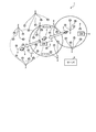
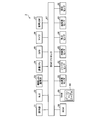
- FIG. 1 is an explanatory diagram illustrating an example of a position detection system according to the present embodiment.
- FIG. 2 is an explanatory diagram illustrating an example of transition of positioning areas related to devices in the position detection system.
- FIG. 3 is an explanatory diagram illustrating an example of a hardware configuration of the server.
- FIG. 4 is an explanatory diagram illustrating an example of a configuration in the beacon information DB.
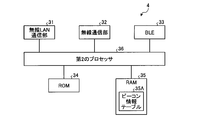
- FIG. 5 is an explanatory diagram illustrating an example of a hardware configuration of the GW.
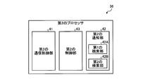
- FIG. 6 is an explanatory diagram illustrating an example of a functional configuration of the second processor.
- FIG. 7 is an explanatory diagram illustrating an example of a hardware configuration of a device.
- FIG. 8 is an explanatory diagram illustrating an example of a functional configuration of the third processor.
- FIG. 1 is an explanatory diagram illustrating an example of a position detection system according to the present embodiment.
- FIG. 2 is an explanatory diagram illustrating an example of transition of positioning areas related to devices
- FIG. 9 is an explanatory diagram showing an example of the configuration of the beacon map table.
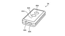
- FIG. 10 is a perspective view showing an example of a location badge.
- FIG. 11 is a perspective view showing an example of a location badge.
- FIG. 12 is a sequence diagram illustrating an example of a processing operation of the position detection system.
- FIG. 13 is an explanatory diagram illustrating an example of the rewriting operation of the first control unit of the beacon map table.
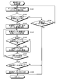
- FIG. 14 is a flowchart illustrating an example of the processing operation of the first processor in the server related to the registration process.
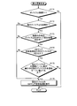
- FIG. 15 is a flowchart illustrating an example of the processing operation of the second processor in the GW related to the GW update process.
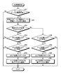
- FIG. 16 is a flowchart illustrating an example of the processing operation of the third processor in the device related to the startup process.
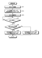
- FIG. 17 is a flowchart illustrating an example of the processing operation of the third processor in the device related to the extension setting process.
- FIG. 18 is a flowchart illustrating an example of the processing operation of the third processor in the device related to the rewrite request processing.
- FIG. 19 is a flowchart illustrating an example of the processing operation of the third processor in the device related to the update process.
- FIG. 20 is a flowchart illustrating an example of the processing operation of the second processor in the GW related to the GW map update processing.
- FIG. 21 is a flowchart illustrating an example of the processing operation of the second processor in the GW related to the reuse list search process.
- FIG. 22 is a flowchart illustrating an example of the processing operation of the second processor in the GW related to the additional list search process.
- FIG. 23 is a flowchart illustrating an example of the processing operation of the second processor in the GW related to the priority update process.
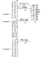
- FIG. 24 is an explanatory diagram illustrating an example of the rewriting operation of the first control unit of the beacon map table.
- FIG. 1 is an explanatory diagram showing an example of the position detection system 1 of the present embodiment.
- a position detection system 1 shown in FIG. 1 includes a plurality of beacons 2, a device 3, a GW (Gateway) 4, and a server 5.
- the beacon 2 is a transmission device that transmits a beacon including a beacon ID.
- the device 3 is a communication device with a built-in sensor function that collects various types of information.
- the GW 4 is a distribution device that manages the beacon 2 within the wireless range of the own device and distributes the beacon information of the beacon 2 within the wireless range to the device 3.
- the beacon information is information for managing position information and radio wave intensity (RSSI: Received Signal Strength Indicator) for each beacon ID for identifying a beacon.
- the server 5 controls the entire position detection system 1 and centrally manages the beacon information of all the beacons 2 in the position detection system 1.
- RSSI Received Signal Strength Indicator
- the device 3 acquires the beacon information from the GW 4 and registers the acquired beacon information in the beacon map table 68.
- the device 3 receives a beacon from the nearby beacon 2, refers to the beacon information in the beacon map table 68, and detects the position of the own device based on the position information of the beacon 2 corresponding to the beacon ID in the received beacon. .
- the device 3 notifies the collected sensor information to the GW 4.
- the GW 4 notifies the server 5 of the collected sensor information of each device 3.
- the server 5 analyzes the sensor information of each device 3.
- the server 5 can manage the worker's state based on the sensor information analysis result of each device 3 and can manage the worker's position based on the position detection result of each device 3.
- FIG. 2 is an explanatory diagram showing an example of the movement transition of the device 3 in the position detection system 1. Since the device 3 has a finite capacity in the beacon map table 68, only beacon information corresponding to up to 250 beacon IDs can be registered. Therefore, for example, every time the device 3 moves in the position detection system 1, the beacon information in the beacon map table 68 is updated.
- FIG. 3 is an explanatory diagram showing an example of the hardware configuration of the server 5.
- the server 5 illustrated in FIG. 3 includes a communication IF (Interface) 11, a ROM (Read Only Memory) 12, a RAM (Random Access Memory) 13, a DB (Database) 14, and a first processor 15.
- the communication IF 11 is an IF that manages communication with the GW 4.
- the ROM 12 is an area for storing information such as various programs.
- the RAM 13 is an area for storing various information.
- DB14 has sensor DB21, beacon information DB22, device DB23, and analysis DB24.
- the sensor DB 21 is a DB that manages sensor information for each sensor item for each device 3.
- the sensor item includes, for example, an acceleration sensor value, a gyro sensor value, a geomagnetic sensor value, an atmospheric pressure sensor value, a temperature / humidity sensor value, a pulse sensor value, and the like.
- the beacon information DB 22 is a DB that manages the beacon information of all the beacons 2 in the position detection system 1.
- FIG. 4 is an explanatory diagram showing an example of the configuration of the beacon information DB 22.
- the beacon information DB 22 illustrated in FIG. 4 manages the beacon ID 22A, the position information 22B, the RSSI 22C, and the neighborhood beacon ID 22D in association with each other.
- the beacon ID 22A is an ID for identifying the beacon 2.
- the position information 22B is the latitude, longitude, and altitude that are the positions of the beacon 2.
- RSSI 22 ⁇ / b> C is a threshold value of the allowable electric field strength of beacon 2.
- the neighborhood beacon ID 22D manages a beacon ID that identifies up to 250 beacons in the vicinity of the beacon 2.
- the device DB 23 is a DB that manages device types in the position detection system 1.
- the analysis DB 24 is a DB that manages analysis results obtained by analyzing sensor information of each device 3.
- the first processor 15 controls the entire server 5.
- FIG. 5 is an explanatory diagram showing an example of the hardware configuration of the GW 4.
- the GW 4 illustrated in FIG. 5 includes a wireless LAN communication unit 31, a wireless communication unit 32, a BLE (Bluetooth (registered trademark) function) 33, a ROM 34, a RAM 35, and a second processor 36.
- the wireless LAN communication unit 31 is a communication unit that manages wireless LAN communication.
- the wireless communication unit 32 is a communication unit that manages wireless communication with the server 5.
- the BLE 33 is, for example, a communication unit that manages BLE communication with the device 3.
- the ROM 34 is an area for storing information such as various programs.
- the RAM 35 is an area for storing various information.
- the RAM 35 has a beacon information table 35A for managing beacon information for each beacon 2 within the wireless range managed by the own device.
- the second processor 36 controls the entire GW 4.
- the second processor 36 develops a program stored in the ROM 34 in the RAM 35 and executes a processing function using the program developed on the RAM 35 as a process.
- FIG. 6 is an explanatory diagram illustrating an example of a functional configuration of the second processor 36.
- the second processor 36 illustrated in FIG. 6 includes a second communication control unit 41, a second notification unit 42, and a second control unit 43 as processing functions.
- the second communication control unit 41 is, for example, a communication control unit that controls BLE communication with the device 3.
- the second notification unit 42 notifies the device 3 of an inquiry request such as the nearest neighbor beacon ID, the number of unregistered beacons, and the registered beacon ID described later.
- the second notification unit 42 includes a first search unit 42A and a second search unit 42B.
- the first search unit 42A is a processing unit that executes a reuse list search process to be described later.
- the second search unit 42B is a processing unit that executes an additional list search process to be described later.
- the second control unit 43 controls the entire second processor 36.
- the device 3 includes, for example, a badge type device in addition to a band type device.
- the band-type device is, for example, a device that is worn on the wrist of an operator.
- the badge-type device includes, for example, a type that is worn on a worker's clothes and a type that is worn on a worker's luggage.
- FIG. 7 is an explanatory diagram showing an example of the hardware configuration of the device 3.
- the device 3 shown in FIG. 7 exemplifies a band type device, for example.
- the device 3 shown in FIG. 7 includes an operation unit 51, a BLE 52, a wireless LAN communication unit 53, a communication CPU 54, a GPS (Global Positioning System) 55, a microphone 56, a voice DSP (Digital Signal Processor) 57, A ROM 58 and a RAM 59 are included.
- the device 3 includes an acceleration sensor 61, a gyro sensor 62, a geomagnetic sensor 63, an atmospheric pressure sensor 64, a temperature / humidity sensor 65, a pulse sensor 66, and a third processor 67.
- the operation unit 51 inputs various commands.
- the BLE 52 executes BLE communication with the beacon 2 and with the GW 4.
- the wireless LAN communication unit 53 performs wireless LAN communication.
- the communication CPU 54 controls the wireless LAN communication unit 53.
- the GPS 55 detects the position of the device 3 using the GPS signal.
- the microphone 56 is an input IF for inputting sound.
- the audio DSP 57 is a processing unit that digitally processes input audio.
- the ROM 58 is an area for storing various programs.
- the RAM 59 is an area for storing various information.
- the acceleration sensor 61 is a sensor that detects the acceleration of the device 3.
- the gyro sensor 62 is a sensor that detects the angular velocity of the device 3.
- the geomagnetic sensor 63 is a sensor that detects the direction.
- the atmospheric pressure sensor 64 is a sensor that detects atmospheric pressure.
- the temperature / humidity sensor 65 is a sensor for detecting temperature / humidity.
- the pulse sensor 66 is a sensor that counts the pulse rate of the worker who wears it.
- the RAM 59 has a beacon map table 68 in addition to a work area for executing processing functions.
- the third processor 67 expands the program stored in the ROM 58 in the RAM 59 and executes a processing function using the program expanded on the RAM 59 as a process.
- FIG. 8 is an explanatory diagram showing an example of the functional configuration of the third processor 67.
- the third processor 67 shown in FIG. 8 includes a first communication control unit 71, a first notification unit 72, a position detection unit 73, and a first control unit 74 as processing functions.
- the first communication control unit 71 is, for example, a communication control unit that controls BLE communication with the GW 4.
- the first notification unit 72 includes an acquisition unit 72A.
- the acquisition unit 72A acquires the nearest neighbor beacon ID in response to the inquiry request for the nearest neighbor beacon ID from the GW 4.
- the nearest neighbor beacon ID is the beacon ID of the beacon 2 having the maximum reception intensity among the nearby beacons 2 communicating with the device 3.
- the first notification unit 72 notifies the GW 4 of the inquiry request of the nearest beacon ID acquired by the acquisition unit 72A.
- the acquisition unit 72A acquires the number of unregistered beacons in response to an unregistered beacon inquiry request from the GW 4.
- the number of unregistered beacons is the number of unregistered beacon IDs in the beacon map table 68, that is, the number of empty entries.
- the first notification unit 72 notifies the GW 4 of the inquiry request of the number of unregistered beacons.
- the acquiring unit 72A acquires the registered beacon ID in response to the registered beacon ID inquiry request from the GW 4.
- the registered beacon ID is a registered beacon ID in the beacon map table 68.
- the first notification unit 72 notifies the registered beacon ID to the GW 4 of the inquiry request.
- the position detection unit 73 extracts the beacon ID of the received beacon, refers to the received beacon position information corresponding to the extracted beacon ID in the beacon map table 68, and detects the current position of the device 3 from the received beacon position information. .
- the first control unit 74 controls the entire third processor 67.
- the first control unit 74 updates the beacon information in the beacon map table 68 based on the reuse beacon list and the additional beacon list from the GW 4.
- the reuse beacon list is a list of beacon IDs to be reused among the beacon information registered in the beacon map table 68.
- the additional beacon list is a list of beacon IDs that are newly registered in the beacon map table 68.
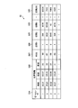
- FIG. 9 is an explanatory diagram showing an example of the beacon map table 68.
- the beacon map table 68 illustrated in FIG. 9 includes a beacon ID 68A, position information 68B, and RSSI 68C.
- the beacon ID 68 ⁇ / b> A is an ID for identifying the beacon 2 in the vicinity of the device 3.
- the position information 68B is information for identifying the installation position of the beacon 2, for example, latitude, longitude, and altitude.
- RSSI 68C is an allowable threshold value for the received radio wave intensity of beacon 2.
- FIG. 10 is a perspective view showing an example of the location badge 3A.
- a location badge 3A shown in FIG. 10 is a badge-type device attached to an operator.
- the location badge 3A has an atmospheric pressure sensor hole 81A, a sensor hole 82A, a notification button 83A, a status LED 84A, and a power button 85A.
- FIG. 11 is a perspective view showing an example of the location badge 3B.
- a location badge 3B shown in FIG. 11 is a badge type device attached to a part.
- Location badge 3B has barometric pressure sensor hole 81B, sensor hole 82B, status LED 84B, and power button 85B.
- FIG. 12 is a sequence diagram illustrating an example of a processing operation of the position detection system 1.
- the server 5 arranges the beacon information (step S12) in response to a beacon information registration operation such as deletion, addition, or change of the beacon 2 in the position detection system 1 (step S11).
- the server 5 registers the beacon information in the beacon information DB 22 (Step S13).
- the server 5 notifies the GW 4 of the beacon information (step S15).
- the server 5 notifies the GW 4 of the area expansion flag ON (step S16).
- the area expansion flag is ON when the number of beacon information in the position detection system 1 exceeds 251, and is OFF when the number of beacon information is less than 251.
- Step S17 the GW4 registers beacon information in beacon information table 35A, when beacon information is received in Step S15 (Step S17).
- the GW 4 notifies the device 3 of the area extension flag ON (step S18).
- the device 3 receives the area expansion flag ON, the device 3 turns on the area expansion flag (step S19), and notifies the GW 4 of a connection request for the rewrite request flag ON (step S20).
- the GW 4 notifies the device 3 of the inquiry request for the nearest beacon ID (step S21).
- the device 3 searches for the nearest beacon ID (step S22) and notifies the GW 4 of the nearest beacon ID (step S23).
- the GW 4 notifies the device 3 of an inquiry request for the number of unregistered beacons (step S24).
- the device 3 calculates the number of unregistered beacons in the beacon map table 68 (step S25) and notifies the GW 4 of the number of unregistered beacons (step S26).
- step S27 When receiving the inquiry request for the registered beacon ID, the device 3 searches for the registered beacon ID in the beacon map table 68 (step S28), and notifies the GW 4 of the registered beacon ID (step S29).
- the GW 4 acquires a reuse beacon list based on the nearest beacon ID and the registered beacon ID (step S30), and notifies the device 3 of the reuse beacon list (step S31). Furthermore, the GW 4 acquires an additional beacon list based on the nearest beacon ID and the registered beacon ID (step S32), and notifies the device 3 of the additional beacon list (step S33). The device 3 updates the beacon information in the beacon map table 68 based on the reuse beacon list and the additional beacon list (step S34), disconnects the BLE communication with the GW 4 (step S35), and is shown in FIG. The processing operation is terminated.
- FIG. 13 is an explanatory diagram showing an example of the rewriting operation of the first control unit 74 of the beacon map table 68.
- the beacon map table 68 is, for example, a ring buffer method.
- the first control unit 74 can register 250 pieces of beacon information in the beacon map table 68.
- a case where a beacon ID is registered in the beacon map table 68 is exemplified as beacon information.
- the position information 68B and RSSI 68C are registered in the beacon map table 68. Is omitted.
- beacon information for beacon IDs “001” to “250” is stored in the beacon map table 68 (step S101).
- the first control unit 74 receives a reuse beacon list from the GW 4 (step S102).
- the reuse beacon list is, for example, beacon IDs “001”, “002”, “003”, “011”, “012”, and “013”.
- the first control unit 74 deletes beacon IDs other than the beacon IDs 68 ⁇ / b> A of “001”, “002”, “003”, “011”, “012”, and “013” from the beacon map table 68. (Step S103). It is assumed that the deleted free area is “000”. Furthermore, the first control unit 74 receives an additional beacon list from the GW 4 (step S104).
- the additional beacon list is, for example, beacon IDs “251”, “252”, “253”, “254”, “255”, and “256”.
- the first control unit 74 packs the beacon IDs “251”, “252”, “253”, “254”, “255”, and “256” in the additional beacon list in the free space in the beacon map table 68. Are additionally registered (step S105). As a result, since the device 3 can register the difference information in the beacon map table 68 while preventing overwriting deletion of the reuse beacon ID based on the reuse beacon list and the registered beacon list, the registration time can be shortened. .
- FIG. 14 is a flowchart showing an example of the processing operation of the first processor 15 in the server 5 involved in the registration process.
- the first processor 15 in the server 5 determines whether or not a beacon information registration operation has been detected (step S41). If the first processor 15 detects a beacon information registration operation (Yes at Step S41), the first processor 15 organizes the beacon information (Step S42), and registers the beacon information in the beacon information DB 22 (Step S43).
- the first processor 15 determines whether or not the number of registered beacon information in the beacon information DB 22 is 251 or more (step S44). When the number of registered beacon information is 251 or more (Yes at Step S44), the first processor 15 notifies the GW 4 of the beacon information and the area expansion flag ON (Step S45), and ends the processing operation illustrated in FIG. .
- the first processor 15 When the number of registered beacon information is not 251 or more (No at Step S44), the first processor 15 notifies the GW 4 of the beacon information and the area expansion flag OFF (Step S46), and ends the processing operation illustrated in FIG. .
- the first processor 15 does not detect the beacon information registration operation (No at Step S41), the first processor 15 ends the processing operation illustrated in FIG.
- the server 5 notifies the GW 4 of the beacon information and the area extension flag ON when the number of registered beacon information is 251 or more according to the registration operation. As a result, the GW 4 can set the area expansion flag ON.
- the server 5 If the registered number of beacon information is not 251 or more, the server 5 notifies the GW 4 of beacon information and area extension flag OFF. As a result, the GW 4 can set the area expansion flag OFF.
- FIG. 15 is a flowchart showing an example of the processing operation of the second processor 36 in the GW 4 related to the GW update process.
- the second processor 36 in the GW 4 determines whether or not beacon information has been received from the server 5 (step S51).
- the second processor 36 registers the received beacon information in the beacon information table 35A (Step S52).
- the second processor 36 determines whether or not the current area expansion flag is ON after the beacon information is registered (step S53). If the current area expansion flag is ON (Yes at Step S53), the second processor 36 determines whether or not the area expansion flag ON is received (Step S54). When receiving the area expansion flag ON (Yes at Step S54), the second processor 36 ends the processing operation shown in FIG. 15 while keeping the area expansion flag ON.
- the second processor 36 determines whether or not the area expansion flag OFF has been received (Step S55).
- the second processor 36 receives the area expansion flag OFF (Yes at Step S55)
- the second processor 36 turns the area expansion flag OFF (Step S56), notifies each device 3 of the area expansion flag OFF (Step S57), and FIG.
- the processing operation shown in FIG. It is assumed that the second processor 36 recognizes whether or not the area expansion flag is the device 3 that can be set to ON / OFF.
- the second processor 36 When the second processor 36 does not receive the area expansion flag OFF (No at Step S55), the second processor 36 ends the processing operation shown in FIG. If the current area expansion flag is not ON (No at Step S53), that is, if the current area expansion flag is OFF, the second processor 36 determines whether or not the area expansion flag OFF has been received (Step S58). ). When receiving the area expansion flag OFF (Yes at Step S58), the second processor 36 ends the processing operation shown in FIG. 15 while keeping the area expansion flag OFF.
- the second processor 36 determines whether or not the area expansion flag ON has been received (Step S59).
- the second processor 36 receives the area expansion flag ON (Yes at step S59)
- the second processor 36 turns the area expansion flag ON (step S60), notifies the device 3 of the area expansion flag ON (step S61), and FIG. The processing operation shown in FIG.
- the second processor 36 When the second processor 36 does not receive the area expansion flag ON (No at Step S59), the second processor 36 ends the processing operation shown in FIG. 15 while keeping the area expansion flag OFF. When the second processor 36 has not received the beacon information (No at Step S51), the second processor 36 ends the processing operation illustrated in FIG.
- GW 4 sets the area expansion flag to ON when the currently set area expansion flag is OFF and the area expansion flag ON is received from the server 5. As a result, the GW 4 can set the area expansion flag to ON.
- GW 4 sets the area expansion flag to OFF when the currently set area expansion flag is ON and the area expansion flag OFF is received from the server 5. As a result, the GW 4 can set the area expansion flag to OFF.
- FIG. 16 is a flowchart showing an example of the processing operation of the third processor 67 in the device 3 related to the startup process.
- the third processor 67 in the device 3 activates each sensor in response to power activation (step S71), sets the area expansion flag to OFF, and sets the initial connection completed flag to OFF (step S72).
- the initial connection completed flag is a flag for identifying whether or not the initial connection has been made through BLE communication with the GW 4.
- the third processor 67 makes a connection request to the GW 4 (step S73), and determines whether or not it is connected to the GW 4 (step S74). When the third processor 67 is connected to the GW 4 (Yes at Step S74), the third processor 67 determines whether or not the area expansion flag ON is received from the GW 4 (Step S75). When the third processor 67 receives the area expansion flag ON from the GW 4 (Yes at Step S75), the third processor 67 sets the initial connection completed flag to ON and the area expansion flag to ON (Step S76), and performs the processing operation shown in FIG. finish.
- Step S75 If the third processor 67 does not receive the area extension flag ON from the GW 4 (No at Step S75), the third processor 67 sets the initial connection completed flag to ON and the area extension flag to OFF (Step S77), and performs the processing shown in FIG. End the operation. If the third processor 67 is not connected to the GW 4 (No at Step S74), the third processor 67 proceeds to Step S74 in order to determine whether or not the GW 4 is connected.
- device 3 When device 3 is activated in response to power activation, device 3 sets the area expansion flag to OFF, the initial connection completed flag to OFF, and requests connection to GW 4.
- the device 3 connects to the GW 4 in response to the connection request, and when receiving the area expansion flag ON from the GW 4, the device 3 sets the area expansion flag to ON and the initial connection completed flag to ON. As a result, the device 3 is in a state where the rewriting update of the beacon map area 68 is possible.
- FIG. 17 is a flowchart showing an example of the processing operation of the third processor 67 in the device 3 related to the extension setting process.
- the third processor 67 in the device 3 determines whether or not it is connected to the GW 4 (step S81). When the third processor 67 is connected to the GW 4 (Yes at Step S81), the third processor 67 determines whether or not the current area expansion flag is ON (Step S82). If the current area expansion flag is ON (Yes at Step S82), the third processor 67 determines whether or not the area expansion flag ON is received from the GW 4 (Step S83). When the third processor 67 receives the area expansion flag ON (Yes at step S83), the third processor 67 ends the processing operation shown in FIG.
- the third processor 67 determines whether or not the area expansion flag OFF has been received (Step S84). When the third processor 67 receives the area expansion flag OFF (Yes at step S84), the third processor 67 turns off the area expansion flag (step S85) and ends the processing operation shown in FIG. If the third processor 67 does not receive the area expansion flag OFF (No at step S84), the third processor 67 ends the processing operation shown in FIG.
- the third processor 67 determines whether or not the area expansion flag OFF is received from the GW 4 ( Step S86). When the third processor 67 receives the area expansion flag OFF (Yes at Step S86), the third processor 67 ends the processing operation shown in FIG.
- the third processor 67 determines whether or not the area expansion flag ON is received from the GW 4 (Step S87). When the third processor 67 receives the area expansion flag ON (Yes at Step S87), the third processor 67 sets the area expansion flag to ON (Step S88), and ends the processing operation shown in FIG.
- Device 3 sets the area expansion flag to ON when the currently set area expansion flag is OFF and the area expansion flag ON is received from GW 4. As a result, the device 3 can set the area expansion flag to ON.
- Device 3 sets the area expansion flag to OFF when the currently set area expansion flag is ON and the area expansion flag OFF is received from GW 4. As a result, the device 3 can set the area expansion flag to OFF.
- FIG. 18 is a flowchart showing an example of the processing operation of the third processor 67 in the device 3 related to the rewrite request processing.
- the third processor 67 in the device 3 acquires sensor values of the acceleration sensor 61, the gyro sensor 62, the geomagnetic sensor 63, the atmospheric pressure sensor 64, and the like (step S91).
- the third processor 67 acquires the result of the movement detection algorithm (step S92).
- the movement detection algorithm is an algorithm for detecting movement of the device 3 using the acquired sensor value.
- the third processor 67 acquires the ratio of the unregistered beacon 2 in the beacon map table 68 among the received beacons received within the predetermined period, that is, the ratio of the unregistered beacon whose position information could not be detected. (Step S93).
- the third processor 67 determines whether or not there is a predetermined change in the sensor value (step S95). If there is no predetermined change in the sensor value (No at Step S95), the third processor 67 determines whether movement has been detected (Step S96). Note that the third processor 67 determines movement detection based on the detection result of the movement detection algorithm. If the movement is not detected (No at Step S96), the third processor 67 determines whether the unregistered beacon ratio is 75% or more (Step S97). If the unregistered beacon ratio is not 75% or more (No at Step S97), the third processor 67 proceeds to Step S91 so as to obtain the sensor value.
- the third processor 67 determines that the position of the device 3 has changed, and notifies the GW 4 of a connection request with the rewrite request flag ON (step S98).
- the rewrite request flag is set to ON in order to request rewriting update of the beacon map table 68.
- the third processor 67 notifies the connection request of the rewrite request flag ON to the GW 4, and then disconnects the BLE communication with the beacon 2 (step S99) and ends the processing operation shown in FIG.
- Step S96 If there is movement detection (Yes at Step S96), the third processor 67 determines that the position of the device 3 has changed, and proceeds to Step S98 to notify the GW 4 of a connection request with the rewrite request flag ON. If the unregistered beacon ratio is 75% or more (Yes at Step S97), the third processor 67 proceeds to Step S98 in order to notify the GW 4 of the connection request with the rewrite request flag ON.
- the device 3 When the sensor value has a predetermined change, the device 3 notifies the GW 4 of a connection request with the rewrite request flag ON. As a result, the device 3 requests the GW 4 to rewrite and update the beacon map table 68.
- the device 3 When the device 3 detects movement, the device 3 notifies the GW 4 of a connection request with the rewrite request flag ON. As a result, the device 3 requests the GW 4 to rewrite and update the beacon map table 68.
- the device 3 If the unregistered beacon ratio is 75% or more, the device 3 notifies the GW 4 of a connection request with the rewrite request flag ON. As a result, the device 3 requests the GW 4 to rewrite and update the beacon map table 68.
- the device 3 notifies the GW 4 of a connection request with the rewrite request flag ON when the sensor value has a predetermined change, when movement is detected, or when the unregistered beacon ratio is 75% or more. However, when the area expansion flag of the device 3 is ON and the initial connection completed flag is ON, the device 3 may notify the connection request of the rewrite request flag ON to the GW 4 every predetermined period.
- FIG. 19 is a flowchart showing an example of the processing operation of the third processor 67 in the device 3 related to the update process.
- the third processor 67 in the device 3 determines whether or not an inquiry request for the nearest beacon ID from the GW 4 has been received (step S101).
- the third processor 67 determines whether there is a nearest beacon ID (Step S102).
- the third processor 67 notifies the GW 4 of the nearest beacon ID (Step S103).
- the third processor 67 determines whether an inquiry request for the number of unregistered beacons from the GW 4 has been received (step S104). When the third processor 67 receives an inquiry request for the number of unregistered beacons (Yes at Step S104), the third processor 67 notifies the GW 4 of the number of unregistered beacons (Step S105). After the notification of the number of unregistered beacons, the third processor 67 determines whether or not an inquiry request for a registered beacon ID from the GW 4 has been received (step S106). When the third processor 67 receives an inquiry request for a registered beacon ID (Yes at Step S106), the third processor 67 notifies the GW 4 of the registered beacon ID (Step S107).
- the third processor 67 determines whether or not a reuse beacon list has been received from the GW 4 (step S108). When the third processor 67 receives the reuse beacon list (Yes at Step S108), the third processor 67 notifies the GW 4 of the response of the reuse beacon list (Step S109).
- the third processor 67 deletes the beacon IDs other than the reuse beacon IDs in the reuse beacon list from the beacon map table 68 (step S110), and determines whether an additional beacon list is received from the GW 4 or not. Determination is made (step S111).
- the third processor 67 notifies the GW 4 of the response of the additional beacon list (Step S112).
- the third processor 67 extracts a beacon ID, position information, and RSSI from the additional beacon list (step S113).
- the third processor 67 additionally registers the extracted beacon ID, position information, and RSSI in a free area in the beacon map table 68 (step S114), and ends the processing operation shown in FIG. If the third processor 67 does not receive the nearest beacon ID inquiry request (No at step S101), the third processor 67 ends the processing operation illustrated in FIG.
- the third processor 67 proceeds to step S106 to determine whether or not an inquiry request for a registered beacon ID has been received. If the third processor 67 has not received an unregistered beacon inquiry request (step S104), the third processor 67 proceeds to step S104. If the third processor 67 does not receive the registered beacon ID inquiry request (step S106), the third processor 67 proceeds to step S106. If the third processor 67 does not receive the reuse beacon list (No at Step S108), the third processor 67 proceeds to Step S108. If the third processor 67 does not receive the additional beacon list (No at Step S111), the third processor 67 proceeds to Step S111.
- the device 3 notifies the GW 4 of the nearest beacon ID, the number of unregistered beacons, and the registered beacon ID in response to the inquiry request.
- the GW 4 can generate the reuse beacon list and the additional beacon list based on the nearest neighbor beacon ID, the number of unregistered beacons, and the registered beacon ID of the device 3.
- FIG. 20 is a flowchart showing an example of the processing operation of the second processor 36 in the GW 4 related to the GW map update process.
- the second processor 36 in the GW 4 determines whether or not a connection request is received from the device 3 (step S121).
- the second processor 36 determines whether or not the rewrite request flag in the connection request is ON (Step S122).
- the second processor 36 notifies the connection request device 3 of the inquiry request for the nearest beacon ID (Step S123). The second processor 36 determines whether or not the nearest beacon ID is received from the connection requesting device 3 (step S124). When the second processor 36 receives the nearest beacon ID from the connection requesting device 3 (Yes in step S124), the second processor 36 notifies the connection requesting device 3 of an inquiry request for the number of unregistered beacons (step S125). The second processor 36 determines whether or not the number of unregistered beacons has been received from the connection requesting device 3 (step S126).
- the second processor 36 When the second processor 36 receives the number of unregistered beacons from the connection requesting device 3 (Yes in step S126), the second processor 36 notifies the connection requesting device 3 of the inquiry request for the registered beacon ID (step S127). The second processor 36 determines whether or not a registered beacon ID has been received from the connection requesting device 3 (step S128).
- the second processor 36 executes a reuse list search process for searching for a reuse beacon list (step S129). After searching the reuse beacon list, the second processor 36 notifies the connection request device 3 of the reuse beacon list (step S130), and determines whether or not the reuse beacon list response has been received (step S130). Step S131).
- the second processor 36 executes an additional list search process for searching for an additional beacon list (Step S132). After searching the additional beacon list, the second processor 36 notifies the device 3 of the connection request of the additional beacon list (step S133) and determines whether or not a response of the additional beacon list has been received (step S134). . When the second processor 36 receives the response (Yes at step S134), the second processor 36 ends the processing operation shown in FIG.
- the second processor 36 When the second processor 36 does not receive the connection request from the device 3 (No at Step S121) or when the rewrite request flag in the connection request is not ON (No at Step S122), the second processor 36 ends the processing operation illustrated in FIG. To do. If the second processor 36 has not received the nearest beacon ID (No at Step S124), the second processor 36 proceeds to Step S124. If the second processor 36 has not received the number of unregistered beacons (No at Step S126), the second processor 36 proceeds to Step S126. If the second processor 36 does not receive the registered beacon ID (No at Step S128), the second processor 36 proceeds to Step S128. If the second processor 36 does not receive a response (No at Step S131), the second processor 36 proceeds to Step S131. If the second processor 36 has not received a response (No at Step S134), the second processor 36 proceeds to Step S134.
- the GW 4 When the GW 4 receives the nearest neighbor beacon ID and the registered beacon ID from the device 3, the GW 4 generates a reuse beacon list and an additional beacon list using the nearest neighbor beacon ID and the registered beacon ID. As a result, since the GW 4 can notify the device 3 of the reuse beacon list and the additional beacon list as the difference information, the transmission capacity can be minimized.
- FIG. 21 is a flowchart showing an example of the processing operation of the second processor 36 in the GW 4 related to the reuse list search process.
- the second processor 36 in the GW 4 designates beacon information in the beacon information table 35A (step S141), and determines whether the designated beacon information matches the nearest beacon ID (step S142). ).
- the second processor 36 acquires beacon information that matches the nearest neighbor beacon ID (step S143).
- the beacon information includes a beacon ID, position information, RSSI, and a neighboring beacon list.
- the second processor 36 after acquiring the nearest beacon ID matched beacon information, designates the neighborhood beacon ID in the obtained beacon information (step S144), and the designated neighborhood beacon ID matches the registered beacon ID. It is determined whether or not (step S145). When the designated neighborhood beacon ID matches the registered beacon ID (Yes at step S145), the second processor 36 sets the designated neighborhood beacon ID as the reuse beacon ID (step S146), and the undesignated neighborhood beacon ID is not designated. It is determined whether there is a nearby beacon ID (step S147).
- step S147 If there is an unspecified neighborhood beacon ID (Yes at step S147), the second processor 36 proceeds to step S144 to designate the neighborhood beacon ID. If there is no unspecified neighborhood beacon ID (No at Step S147), the second processor 36 determines whether there is a reuse beacon ID (Step S148).
- the second processor 36 acquires a reuse beacon list (Step S149), and ends the processing operation shown in FIG. If there is no reuse beacon ID (No at Step S148), the second processor 36 ends the processing operation shown in FIG.
- the second processor 36 determines whether there is undesignated beacon information (Step S150). If there is undesignated beacon information (Yes at Step S150), the second processor 36 proceeds to Step S141 to designate the beacon information. If there is no undesignated beacon information (No at Step S150), the second processor 36 ends the processing operation shown in FIG.
- step S145 the second processor 36 proceeds to step S147 to determine whether there is an undesignated neighborhood beacon ID. .
- the GW4 extracts the neighboring beacon ID corresponding to the nearest neighbor beacon ID from the beacon information table 35A.
- the GW 4 notifies the device 3 of a beacon ID that matches the registered beacon ID among the extracted neighboring beacon IDs as a reuse beacon list.
- the device 3 can prevent the reuse beacon from being overwritten in the beacon map table 68 using the reuse beacon list.
- FIG. 22 is a flowchart showing an example of the processing operation of the second processor 36 in the GW 4 related to the additional list search process.
- the second processor 36 in the GW 4 specifies the beacon information in the beacon information table 35A (step S161), and determines whether the specified beacon information matches the nearest beacon ID (step S162). ).
- the second processor 36 acquires beacon information that matches the nearest neighbor beacon ID (Step S163). Further, the second processor 36 acquires a neighboring beacon ID in the acquired beacon information (step S164).
- the second processor 36 acquires the location information and RSSI of the neighboring beacon ID in the acquired beacon information (step S165). Furthermore, the second processor 36 generates an additional beacon list with these neighboring beacon IDs, position information for each neighboring beacon ID, and RSSI (step S166), and ends the processing operation illustrated in FIG.
- the second processor 36 determines whether there is undesignated beacon information (step S167). If there is undesignated beacon information (Yes at Step S167), the second processor 36 proceeds to Step S161 to designate the beacon information. If there is no undesignated beacon information (No at Step S167), the second processor 36 ends the processing operation shown in FIG.
- the GW4 extracts the neighboring beacon ID corresponding to the nearest neighbor beacon ID from the beacon information table 35A.
- the GW 4 extracts position information and RSSI for each extracted neighboring beacon ID. Further, the GW 4 generates an additional beacon list with the extracted neighboring beacon ID, position information, and RSSI, and notifies the device 3 of the additional beacon list. As a result, the device 3 can register additional beacon information in the beacon map table 68 using the additional beacon list.
- FIG. 23 is a flowchart showing an example of the processing operation of the second processor 36 in the GW 4 related to the priority update process.
- the GW 4 can execute the GW map update process shown in FIG. 20 with up to seven devices 3.
- the second processor 36 in the GW 4 determines whether or not it is connected to the device 3 (step S171).
- the connection with the device 3 is a state in which, for example, the GW 4 receives a position information request from the device 3 and is connected. If the second processor 36 is currently connected to the device 3 (Yes at Step S171), the second processor 36 determines whether it is also connected to the other device 3 (Step S172). If the second processor 36 is connected to another device 3 (Yes at Step S172), the second processor 36 determines whether or not the GW map update process is being executed with the other device 3 that is connected (Step S172). S173).
- step S173 If the second processor 36 is executing GW map update processing with another connected device 3 (Yes in step S173), the number of devices 3 that are executing the GW map update processing including the designated device 3 is eight or more. It is determined whether or not (step S174).
- the second processor 36 determines that the number of unregistered beacons of the specified device 3 is the number of unregistered beacons of other devices 3 that are being executed. It is determined whether it is larger than (step S175). If the number of unregistered beacons of the designated device 3 is larger than the number of unregistered beacons of another device 3 being executed (Yes at step S175), the second processor 36 performs the GW map update process of the designated device 3. It is preferentially executed (step S176). Then, the processing operation shown in FIG.
- the designated device 3 determines that the number of beacons in the beacon map table 68 is insufficient compared to the other connected devices 3, and preferentially executes the GW map update process.
- the second processor 36 preferentially executes the GW map update process for the designated beacon 3
- the GW map being executed by the device with the smallest number of unregistered beacons among the other connected devices 3 is used.
- the update process is stopped, and the GW map update process of the device 3 is resumed when the GW map update process becomes available.
- Step S171 the processing operation shown in FIG. If the second processor 36 is not connected to another device 3 (No at Step S172), the second processor 36 proceeds to Step S176 to execute the map update process of the designated device 3. If the map update process of the other device 3 is not being executed (No at Step S173), the second processor 36 proceeds to Step S176 to execute the map update process of the designated device 3. If the number of devices 3 that are executing the map update process is not eight or more (No in step S174), the second processor 36 proceeds to step S176 to execute the map update process for the designated device 3.
- the second processor 36 ends the processing operation illustrated in FIG. To do.
- the GW 4 manages the number of unregistered beacons for each device 3, for example.
- the number of devices 3 that are executing the GW map update process including the designated device 3 is eight or more. It is determined whether or not there is.
- the number of unregistered beacons of the specified device 3 is not registered in the other device 3 that is executing the GW map update process. It is determined whether or not it is larger than the number of beacons.
- the GW 4 preferentially executes the GW map update process of the specified device 3.
- the designated device 3 can update the beacon map table 68 with priority.
- the device 3 transmits a connection request including the beacon ID of the beacon 2 that satisfies the predetermined condition among the nearby beacons 2 when detecting the movement of the own device to the GW 4. Furthermore, when the GW 4 receives the connection request, the GW 4 transmits the position information of the beacon ID of the nearby beacon 2 corresponding to the beacon ID in the connection request to the device 3. As a result, since the device 3 can acquire the position information of the beacon 2 that satisfies the predetermined condition from the GW 4, for example, the vicinity beacon ID of the nearest beacon, it can flexibly cope with the change of the measurement range.
- the GW 4 When the GW 4 receives the connection request from the device 3, the GW 4 acquires the beacon ID of the beacon 2 that satisfies the predetermined condition in the connection request, for example, the beacon ID of the neighboring beacon 2 corresponding to the nearest beacon ID. The GW 4 transmits to the device 3 a reuse beacon list of beacon IDs that match the registered beacon ID in the connection request among the beacon IDs of the acquired nearby beacons 2. As a result, the GW 4 can notify the device 3 of the reuse beacon ID.
- the device 3 When the device 3 receives the additional beacon list and the reuse beacon list from the GW 4, the device 3 leaves the registered beacon information of the beacon ID of the reuse beacon list and stores the received additional beacon information in the beacon map table 68. Register additional. As a result, the device 3 can prevent the reuse beacon ID in the beacon map table 68 from being overwritten.
- the device 3 transmits a connection request including the nearest beacon ID of the beacon 2 having the largest RSSI among the neighboring beacons 2 to the GW 4.
- the GW 4 can recognize the beacon 2 near the current position of the device 3.
- the device 3 When the beacon information is registered from the GW 4, the device 3 sequentially registers from the beacon ID position information of the nearby beacon 2 in the order of closeness. As a result, even when communication with the GW 4 is disconnected during writing, the probability of registering the beacon information of the nearby beacon 2 is increased, so that a situation in which the position of the own apparatus cannot be detected can be avoided.
- the device 3 When the device 3 detects the periodic signal from the GW 4, the device 3 transmits a connection request with the rewrite request flag ON to the GW 4. As a result, the device 3 can rewrite and update the beacon map table 68 in accordance with the regular signal from the GW 4.
- the device 3 transmits a connection request with the rewrite request flag ON to the GW 4 when the unregistered ratio of the position information corresponding to the beacon ID of the received beacon is 75% or more. As a result, the device 3 can rewrite and update the beacon map table 68 when the probability that the position information cannot be detected increases.
- the device 3 can hold position information used for position detection by dynamically rewriting the contents of the beacon map table 68. As a result, the positioning range of the position detection system 1 can be flexibly dealt with, for example, scale expansion.
- the GW 4 can acquire the latest beacon information from the GW 4 without accessing the server 5. As a result, the device 3 can shorten the processing time for rewriting and updating the beacon map table 68.
- the device 3 illustrated a method of deleting beacon IDs other than the beacon IDs in the reuse beacon list from the beacon map table 68 and additionally registering the beacon ID, location information, and RSSI in the additional beacon list in the free space.
- it is not limited to this method, and can be changed as appropriate.
- beacon ID, position information, and RSSI were registered in the beacon map table 68, only beacon ID and position information may be registered.
- FIG. 24 is an explanatory diagram showing another example of the rewriting operation of the first control unit 74 of the beacon map table 68.
- the maximum number of beacons in the beacon map table 68 is 10, and the link buffer method is adopted.
- the beacon map table 68 includes a beacon ID “100” in the first area, “101” in the second area, “102” in the third area, “103” in the fourth area, and “103” in the fifth area. It is assumed that “104” is registered (step S180). Further, the beacon map table 68 includes “105” in the sixth area, “106” in the seventh area, “97” in the eighth area, “98” in the ninth area, and “10” in the tenth area. It is assumed that “99” is registered. The next additional position is assumed to be from the eighth area.
- the device 3 notifies the GW 4 of “107” as the nearest beacon ID (step S181).
- the GW 4 obtains a neighborhood beacon ID corresponding to the nearest neighborhood beacon ID “107” from the beacon information table 35A (step S182).
- the neighborhood beacon IDs are “107”, “100”, “101”, “103”, “108”, “109”, “110”, and “111”.
- the device 3 notifies the GW 4 of “100”, “101”, and “103” as registered beacon IDs (step S183).
- the GW 4 notifies the device 3 of the reuse beacon list of the reuse beacon ID that matches the registered beacon among the neighboring beacon IDs (step S184).
- the reuse beacon list is, for example, “100”, “101”, and “103”.
- the device 3 receives “100”, “101”, and “103” as the reuse beacon list from the GW 4. At this time, the device 3 preferentially registers “100”, “101”, and “103” as the reuse beacon list, “100” in the eighth area, and “101” and 10 in the ninth area. "103" is rewritten and registered in the second area (step S185). Further, the device 3 sets “97” in the first area where “100” was previously registered, “98” in the second area where “101” was previously registered, and “103” first. Although “99” is rewritten and registered in the registered fourth area, the next additional position is the first.
- step S186 the device 3 receives “107”, “108”, “109”, “110”, and “111” as the additional beacon list from the GW 4 (step S186).
- Device 3 adds “107” to the first area, “108” to the second area, “109” to the third area, “110” to the fourth area, and “111” to the fifth area Registration is performed (step S187).
- the device 3 preferentially registers the beacon ID of the reuse beacon list from the additional position in the beacon map table 68. Furthermore, the device 3 registers the beacon ID deleted in the additional registration of the beacon ID in the reuse beacon list in the area before the reuse beacon addition. Then, the device 3 sequentially registers the beacon IDs in the additional beacon list from the additional position after the additional registration of the reuse beacon. As a result, even when the ring buffer method is adopted, it is possible to avoid a situation in which the reuse beacon ID in the beacon map table 68 is erased by overwrite registration.
- the BLE communication is performed between the device 3 and the GW 4.
- the short-range wireless communication such as WiFi (registered trademark) direct or the like, the normal wireless communication, or the wired communication is used. It may be realized and can be changed as appropriate.
- BLE communication between the device 3 and the beacon 2
- the GW 4 in the above embodiment may be executed by, for example, a tablet terminal or a smartphone, and the server 5 may also be executed by, for example, a tablet terminal or a smartphone, and can be changed as appropriate. Further, the function of the GW 4 may be executed by the server 5 and can be changed as appropriate. In this case, it is assumed that the server 5 executes various processes such as a GW update process with the device 3.
- the device 3 of the above embodiment connects the rewrite request flag ON when, for example, a periodic signal is detected, or when an alarm is detected such as movement detection, a predetermined change in sensor value, or an unregistered beacon ratio of 75% or more.
- the request was notified to GW4.
- the device 3 notifies the GW 4 of a connection request for the rewrite request flag ON in response to the alarm detection.
- each component of each part illustrated does not necessarily need to be physically configured as illustrated.
- the specific form of distribution / integration of each part is not limited to the one shown in the figure, and all or a part thereof may be functionally or physically distributed / integrated in arbitrary units according to various loads and usage conditions. Can be configured.
- each device is executed on a CPU (Central Processing Unit), DSP (Digital Signal Processor), FPGA (Field Programmable Gate Array), etc., all or any part thereof. Also good.
- the various processing functions may be executed entirely or arbitrarily on a program that is analyzed and executed by a CPU or the like, or on hardware based on wired logic.
- RAM Random Access Memory
- ROM Read Only Memory
- SDRAM Serial Dynamic Random Access Memory
- MRAM Magnetic Random Access Memory
- NVRAM Non Volatile Random Access Memory
Landscapes
- Engineering & Computer Science (AREA)
- Physics & Mathematics (AREA)
- General Physics & Mathematics (AREA)
- Radar, Positioning & Navigation (AREA)
- Remote Sensing (AREA)
- Signal Processing (AREA)
- Telephone Function (AREA)
- Position Fixing By Use Of Radio Waves (AREA)
- Mobile Radio Communication Systems (AREA)
Abstract
位置検出システム1は、自装置のビーコンIDを含むビーコンを発信するビーコン2と、各ビーコンの位置情報を配信するGW4と、受信したビーコンID及び位置情報を用いて、自装置の位置を検出するデバイス3とを有する。デバイス3は、自装置の移動を検知した場合に、近傍のビーコン2の内、所定条件を満たすビーコン2のビーコンIDを含む位置情報要求をGW4に送信する。GW4は、位置情報要求を受信した場合に、当該位置情報要求内のビーコンIDに対応した近傍のビーコン2のビーコンIDの位置情報をデバイス3に送信する。
Description
本発明は、位置検出システム、位置検出装置及び位置検出プログラムに関する。
近年、例えば、作業現場で作業する作業者にセンサ機能を内蔵したウェラブルデバイス(以下、単にデバイスと称する)を装着し、そのデバイスで検出したセンサ情報に基づき、作業者の転倒、転落や熱中症等の現場を可視化した業務効率化サービスがある。本サービスには、デバイスの位置を検出する位置検出システムが組み込まれている。位置検出システムは、作業現場の天井や壁等に配置した複数のビーコンと、作業者に装着したデバイスと、ビーコンの位置情報を配信するサーバとを有し、サーバは、ビーコン毎の位置情報をデバイスに配信する。デバイスは、ビーコン毎の位置情報を登録し、ビーコンからのビーコンを受信した場合、受信ビーコンに対応する登録済みの位置情報を用いて、自装置の現在位置を検出する。
しかしながら、位置検出システムのデバイスは、ビーコン毎の位置情報を登録できるメモリ容量が少なく、ビーコンの位置情報の登録件数に制限がある。位置検出システム内の測位範囲を拡張する際にはビーコン設置数が増やすことになるが、デバイスの登録件数の制限によって、ビーコン設置数に制約が生じる。その結果、位置検出システムの測位範囲の規模拡張に対応できない。
一つの側面では、測位範囲の変更に柔軟に対応できる位置検出システム、位置検出装置及び位置検出プログラムを提供することを目的とする。
一つの態様の位置検出システムは、自装置の発信装置IDを含むビーコンを発信する発信装置と、各発信装置の位置情報を配信する配信装置と、受信した発信装置ID及び位置情報を用いて、自装置の位置を検出する通信装置とを有する。前記通信装置は、自装置の移動を検知した場合に、近傍の発信装置の内、所定条件を満たす発信装置の発信装置IDを含む位置情報要求を前記配信装置に送信する。前記配信装置は、前記位置情報要求を受信した場合に、当該位置情報要求内の前記発信装置IDに対応した近傍の発信装置の発信装置IDの位置情報を前記通信装置に送信する。
一つの側面として、測位範囲の変更に柔軟に対応できる。
以下、図面に基づいて、本願の開示する位置検出システム、位置検出装置及び位置検出プログラムの実施例を詳細に説明する。尚、本実施例により、開示技術が限定されるものではない。また、以下に示す実施例は、矛盾を起こさない範囲で適宜組み合わせても良い。
図1は、本実施例の位置検出システム1の一例を示す説明図である。図1に示す位置検出システム1は、複数のビーコン2と、デバイス3と、GW(Gateway)4と、サーバ5とを有する。ビーコン2は、ビーコンIDを含むビーコンを発信する発信装置である。デバイス3は、各種情報を収集するセンサ機能を内蔵した通信装置である。GW4は、自装置の無線範囲内のビーコン2を管理すると共に、無線範囲内のビーコン2のビーコン情報をデバイス3に配信する配信装置である。尚、ビーコン情報は、ビーコンを識別するビーコンID毎の位置情報及び電波強度(RSSI:Received Signal Strength Indicator)を管理する情報である。サーバ5は、位置検出システム1全体を制御すると共に、位置検出システム1内の全ビーコン2のビーコン情報を集中管理する。
デバイス3は、GW4からのビーコン情報を取得し、取得したビーコン情報をビーコンマップテーブル68内に登録する。デバイス3は、近傍のビーコン2からビーコンを受信し、ビーコンマップテーブル68内のビーコン情報を参照し、受信ビーコン内のビーコンIDに対応するビーコン2の位置情報に基づき、自装置の位置を検出する。デバイス3は、収集したセンサ情報をGW4に通知する。GW4は、収集した各デバイス3のセンサ情報をサーバ5に通知する。サーバ5は、各デバイス3のセンサ情報を解析する。サーバ5は、各デバイス3のセンサ情報の解析結果に基づき、作業者の状態を管理すると共に、各デバイス3の位置検出結果に基づき、作業者の位置を管理できる。
図2は、位置検出システム1内のデバイス3の移動遷移の一例を示す説明図である。デバイス3は、ビーコンマップテーブル68内の容量が有限であるため、最大250件までのビーコンIDに対応するビーコン情報しか登録できない。従って、デバイス3は、例えば、位置検出システム1内を移動する都度、ビーコンマップテーブル68内のビーコン情報を更新することになる。
図3は、サーバ5のハードウェア構成の一例を示す説明図である。図3に示すサーバ5は、通信IF(Interface)11と、ROM(Read Only Memory)12と、RAM(Random Access Memory)13と、DB(Database)14と、第1のプロセッサ15とを有する。通信IF11は、GW4との通信を司るIFである。ROM12は、各種プログラム等の情報を記憶する領域である。RAM13は、各種情報を記憶する領域である。DB14は、センサDB21と、ビーコン情報DB22と、デバイスDB23と、解析DB24とを有する。
センサDB21は、デバイス3毎のセンサ項目毎のセンサ情報を管理するDBである。尚、センサ項目は、例えば、加速度センサ値、ジャイロセンサ値、地磁気センサ値、気圧センサ値、温湿度センサ値や脈拍センサ値等である。
ビーコン情報DB22は、位置検出システム1内の全ビーコン2のビーコン情報を管理するDBである。図4は、ビーコン情報DB22の構成の一例を示す説明図である。図4に示すビーコン情報DB22は、ビーコンID22Aと、位置情報22Bと、RSSI22Cと、近傍ビーコンID22Dとを対応付けて管理する。ビーコンID22Aは、ビーコン2を識別するIDである。位置情報22Bは、ビーコン2の位置である緯度、経度及び高度である。RSSI22Cは、ビーコン2の許容電界強度の閾値である。近傍ビーコンID22Dは、当該ビーコン2近傍の最大250個までのビーコンを識別するビーコンIDを管理している。
デバイスDB23は、位置検出システム1内のデバイス種別を管理するDBである。解析DB24は、各デバイス3のセンサ情報を解析した解析結果を管理するDBである。第1のプロセッサ15は、サーバ5全体を制御する。
図5は、GW4のハードウェア構成の一例を示す説明図である。図5に示すGW4は、無線LAN通信部31と、無線通信部32と、BLE(ブルートゥース(登録商標)機能)33と、ROM34と、RAM35と、第2のプロセッサ36とを有する。無線LAN通信部31は、無線LAN通信を司る通信部である。無線通信部32は、例えば、サーバ5との間の無線通信を司る通信部である。BLE33は、例えば、デバイス3との間のBLE通信を司る通信部である。ROM34は、各種プログラム等の情報を記憶する領域である。RAM35は、各種情報を記憶する領域である。RAM35には、自装置が管理する無線範囲内のビーコン2毎のビーコン情報を管理するビーコン情報テーブル35Aを有する。
第2のプロセッサ36は、GW4全体を制御する。第2のプロセッサ36は、ROM34に格納されたプログラムをRAM35に展開し、RAM35上に展開されたプログラムをプロセスとして処理機能を実行する。図6は、第2のプロセッサ36の機能構成の一例を示す説明図である。図6に示す第2のプロセッサ36は、処理機能として、第2の通信制御部41と、第2の通知部42と、第2の制御部43とを有する。第2の通信制御部41は、例えば、デバイス3との間のBLE通信を制御する通信制御部である。第2の通知部42は、デバイス3に対して、後述する最近傍ビーコンID、未登録ビーコン数や登録済みビーコンID等の問合せ要求を通知する。第2の通知部42は、第1の検索部42Aと、第2の検索部42Bとを有する。第1の検索部42Aは、後述する再利用リスト検索処理を実行する処理部である。第2の検索部42Bは、後述する追加リスト検索処理を実行する処理部である。第2の制御部43は、第2のプロセッサ36全体を制御する。
デバイス3は、例えば、バンド型のデバイスの他に、バッジ型のデバイス等がある。バンド型のデバイスは、例えば、作業者の手首に装着するタイプのデバイスである。また、バッジ型のデバイスは、例えば、作業者の衣服に装着するタイプや作業者の荷物に装着するタイプのものがある。
図7は、デバイス3のハードウェア構成の一例を示す説明図である。尚、説明の便宜上、図7に示すデバイス3は、例えば、バンド型のデバイスを例示する。図7に示すデバイス3は、操作部51と、BLE52と、無線LAN通信部53と、通信CPU54と、GPS(Global Positioning System)55と、マイク56と、音声DSP(Digital Signal Processor)57と、ROM58と、RAM59とを有する。デバイス3は、加速度センサ61と、ジャイロセンサ62と、地磁気センサ63と、気圧センサ64と、温湿度センサ65と、脈拍センサ66と、第3のプロセッサ67とを有する。
操作部51は、各種コマンドを入力する。BLE52は、ビーコン2との間、GW4との間のBLE通信を実行する。無線LAN通信部53は、無線LAN通信を実行する。通信CPU54は、無線LAN通信部53を制御する。GPS55は、GPS信号で用いてデバイス3の位置を検出する。マイク56は、音声を入力する入力IFである。音声DSP57は、入力音声をデジタル処理する処理部である。ROM58は、各種プログラムを記憶する領域である。RAM59は、各種情報を記憶する領域である。加速度センサ61は、デバイス3の加速度を検出するセンサである。ジャイロセンサ62は、デバイス3の角速度を検出するセンサである。地磁気センサ63は、方位を検出するセンサである。気圧センサ64は、気圧を検出するセンサである。温湿度センサ65は、温湿度を検出するセンサである。脈拍センサ66は、装着した作業者の脈拍数をカウントするセンサである。RAM59は、処理機能を実行する作業領域の他、ビーコンマップテーブル68を有する。第3のプロセッサ67は、ROM58に格納されたプログラムをRAM59に展開し、RAM59上に展開されたプログラムをプロセスとして処理機能を実行する。
図8は、第3のプロセッサ67の機能構成の一例を示す説明図である。図8に示す第3のプロセッサ67は、処理機能として、第1の通信制御部71と、第1の通知部72と、位置検出部73と、第1の制御部74とを有する。第1の通信制御部71は、例えば、GW4との間のBLE通信を制御する通信制御部である。第1の通知部72は、取得部72Aを有する。
取得部72Aは、GW4からの最近傍ビーコンIDの問合せ要求に対して最近傍ビーコンIDを取得する。尚、最近傍ビーコンIDは、デバイス3で通信中の近傍のビーコン2の内、受信強度が最大のビーコン2のビーコンIDである。第1の通知部72は、取得部72Aにて取得した最近傍ビーコンIDを問合せ要求のGW4に通知する。取得部72Aは、GW4からの未登録ビーコン数の問合せ要求に対して未登録ビーコン数を取得する。未登録ビーコン数は、ビーコンマップテーブル68内の未登録のビーコンID数、すなわち空きエントリ数である。第1の通知部72は、未登録ビーコン数を問合せ要求のGW4に通知する。取得部72Aは、GW4からの登録済みビーコンIDの問合せ要求に対して登録済みビーコンIDを取得する。尚、登録済みビーコンIDは、ビーコンマップテーブル68内の登録済みのビーコンIDである。第1の通知部72は、登録済みビーコンIDを問合せ要求のGW4に通知する。
位置検出部73は、受信ビーコンのビーコンIDを抽出し、ビーコンマップテーブル68内の抽出ビーコンIDに対応する受信ビーコンの位置情報を参照し、受信ビーコンの位置情報からデバイス3の現在位置を検出する。第1の制御部74は、第3のプロセッサ67全体を制御する。第1の制御部74は、GW4からの再利用ビーコンリスト及び追加ビーコンリストに基づき、ビーコンマップテーブル68内のビーコン情報を更新する。再利用ビーコンリストは、ビーコンマップテーブル68内に登録済みのビーコン情報の内、再利用するビーコンIDのリストである。追加ビーコンリストは、ビーコンマップテーブル68内に新たに追加登録するビーコンIDのリストである。
図9は、ビーコンマップテーブル68の一例を示す説明図である。図9に示すビーコンマップテーブル68は、ビーコンID68Aと、位置情報68Bと、RSSI68Cとを有する。ビーコンID68Aは、デバイス3近傍のビーコン2を識別するIDである。位置情報68Bは、ビーコン2の設置位置、例えば、緯度、経度及び高度を識別する情報である。RSSI68Cは、ビーコン2の受信電波強度の許容閾値である。
図10は、ロケーションバッジ3Aの一例を示す斜視図である。図10に示すロケーションバッジ3Aは、作業者に添付するバッジ型のデバイスである。ロケーションバッジ3Aは、気圧センサ孔81Aと、センサ孔82Aと、通知ボタン83Aと、状態LED84Aと、電源ボタン85Aとを有する。
図11は、ロケーションバッジ3Bの一例を示す斜視図である。図11に示すロケーションバッジ3Bは、部品に添付するバッジ型のデバイスである。ロケーションバッジ3Bは、気圧センサ孔81Bと、センサ孔82Bと、状態LED84Bと、電源ボタン85Bとを有する。
次に本実施例の位置検出システム1の動作について説明する。図12は、位置検出システム1の処理動作の一例を示すシーケンス図である。サーバ5は、例えば、位置検出システム1内のビーコン2の削除、追加、変更等のビーコン情報の登録操作に応じて(ステップS11)、ビーコン情報を整理する(ステップS12)。サーバ5は、ビーコン情報をビーコン情報DB22内に登録する(ステップS13)。サーバ5は、ビーコン情報DB22内のビーコン情報が251件以上の場合(ステップS14)、ビーコン情報をGW4に通知する(ステップS15)。更に、サーバ5は、エリア拡張フラグONをGW4に通知する(ステップS16)。尚、エリア拡張フラグは、位置検出システム1内のビーコン情報の件数が251件を超えた場合にON、ビーコン情報の件数が251件未満の場合にOFFとする。
GW4は、ステップS15にてビーコン情報を受信した場合、ビーコン情報をビーコン情報テーブル35A内に登録する(ステップS17)。GW4は、エリア拡張フラグONを受信した場合、エリア拡張フラグONをデバイス3に通知する(ステップS18)。デバイス3は、エリア拡張フラグONを受信した場合、エリア拡張フラグをONにし(ステップS19)、書換要求フラグONの接続要求をGW4に通知する(ステップS20)。
GW4は、書換要求フラグONの接続要求を受信した場合、最近傍ビーコンIDの問合せ要求をデバイス3に通知する(ステップS21)。デバイス3は、最近傍ビーコンIDの問合せ要求を受信した場合、最近傍ビーコンIDを検索し(ステップS22)、その最近傍ビーコンIDをGW4に通知する(ステップS23)。GW4は、最近傍ビーコンIDを受信した場合、未登録ビーコン数の問合せ要求をデバイス3に通知する(ステップS24)。デバイス3は、未登録ビーコン数の問合せ要求を受信した場合、ビーコンマップテーブル68内の未登録ビーコン数を算出し(ステップS25)、その未登録ビーコン数をGW4に通知する(ステップS26)。
GW4は、未登録ビーコン数を受信した場合、登録済みビーコンIDの問合せ要求をデバイス3に通知する(ステップS27)。デバイス3は、登録済みビーコンIDの問合せ要求を受信した場合、ビーコンマップテーブル68内の登録済みビーコンIDを検索し(ステップS28)、その登録済みビーコンIDをGW4に通知する(ステップS29)。
GW4は、最近傍ビーコンID及び登録済みビーコンIDに基づき、再利用ビーコンリストを取得し(ステップS30)、再利用ビーコンリストをデバイス3に通知する(ステップS31)。更に、GW4は、最近傍ビーコンID及び登録済みビーコンIDに基づき、追加ビーコンリストを取得し(ステップS32)、追加ビーコンリストをデバイス3に通知する(ステップS33)。デバイス3は、再利用ビーコンリスト及び追加ビーコンリストに基づき、ビーコンマップテーブル68内のビーコン情報を更新し(ステップS34)、GW4との間のBLE通信を切断し(ステップS35)、図12に示す処理動作を終了する。
図13は、ビーコンマップテーブル68の第1の制御部74の書換動作の一例を示す説明図である。ビーコンマップテーブル68は、例えば、リングバッファ方式である。第1の制御部74は、250件のビーコン情報をビーコンマップテーブル68内に登録できる。尚、説明の便宜上、ビーコン情報としてビーコンIDをビーコンマップテーブル68内に登録する場合を例示するが、ビーコンID68Aの他に、位置情報68B及びRSSI68Cをビーコンマップテーブル68内に登録するため、その説明については省略する。ビーコンマップテーブル68には、ビーコンID“001”~“250”までのビーコン情報が格納されているものとする(ステップS101)。第1の制御部74は、GW4から再利用ビーコンリストを受信する(ステップS102)。再利用ビーコンリストは、例えば、“001”、“002”、“003”、“011”、“012”及び“013”のビーコンIDとする。
第1の制御部74は、再利用ビーコンリストの“001”、“002”、“003”、“011”、“012”及び“013”のビーコンID68A以外のビーコンIDをビーコンマップテーブル68から削除する(ステップS103)。尚、削除した空き領域は“000”とする。更に、第1の制御部74は、GW4から追加ビーコンリストを受信する(ステップS104)。追加ビーコンリストは、例えば、“251”、“252”、“253”、“254”、“255”及び“256”のビーコンIDとする。
第1の制御部74は、追加ビーコンリストの“251”、“252”、“253”、“254”、“255”及び“256”のビーコンIDを、ビーコンマップテーブル68内の空き領域に詰めて追加登録する(ステップS105)。その結果、デバイス3は、再利用ビーコンリスト及び登録済みビーコンリストに基づき、再利用ビーコンIDの上書き削除を防止しながら、差分情報をビーコンマップテーブル68内に登録できるため、登録時間を短縮化できる。
図14は、登録処理に関わるサーバ5内の第1のプロセッサ15の処理動作の一例を示すフローチャートである。図14においてサーバ5内の第1のプロセッサ15は、ビーコン情報の登録操作を検出したか否かを判定する(ステップS41)。第1のプロセッサ15は、ビーコン情報の登録操作を検出した場合(ステップS41肯定)、ビーコン情報を整理し(ステップS42)、ビーコン情報をビーコン情報DB22内に登録する(ステップS43)。
第1のプロセッサ15は、ビーコン情報DB22内にビーコン情報の登録件数が251件以上であるか否かを判定する(ステップS44)。第1のプロセッサ15は、ビーコン情報の登録件数が251件以上の場合(ステップS44肯定)、ビーコン情報及びエリア拡張フラグONをGW4に通知し(ステップS45)、図14に示す処理動作を終了する。
第1のプロセッサ15は、ビーコン情報の登録件数が251件以上でない場合(ステップS44否定)、ビーコン情報及びエリア拡張フラグOFFをGW4に通知し(ステップS46)、図14に示す処理動作を終了する。第1のプロセッサ15は、ビーコン情報の登録操作を検出しなかった場合(ステップS41否定)、図14に示す処理動作を終了する。
サーバ5は、登録操作に応じてビーコン情報の登録件数が251件以上の場合、ビーコン情報及びエリア拡張フラグONをGW4に通知する。その結果、GW4は、エリア拡張フラグONに設定できる。
サーバ5は、ビーコン情報の登録件数が251件以上でない場合、ビーコン情報及びエリア拡張フラグOFFをGW4に通知する。その結果、GW4は、エリア拡張フラグOFFに設定できる。
図15は、GW更新処理に関わるGW4内の第2のプロセッサ36の処理動作の一例を示すフローチャートである。図15においてGW4内の第2のプロセッサ36は、サーバ5からビーコン情報を受信したか否かを判定する(ステップS51)。第2のプロセッサ36は、ビーコン情報を受信した場合(ステップS51肯定)、受信したビーコン情報をビーコン情報テーブル35A内に登録する(ステップS52)。
第2のプロセッサ36は、ビーコン情報の登録後、現在のエリア拡張フラグがONであるか否かを判定する(ステップS53)。第2のプロセッサ36は、現在のエリア拡張フラグがONの場合(ステップS53肯定)、エリア拡張フラグONを受信したか否かを判定する(ステップS54)。第2のプロセッサ36は、エリア拡張フラグONを受信した場合(ステップS54肯定)、エリア拡張フラグONのまま、図15に示す処理動作を終了する。
第2のプロセッサ36は、エリア拡張フラグONを受信しなかった場合(ステップS54否定)、エリア拡張フラグOFFを受信したか否かを判定する(ステップS55)。第2のプロセッサ36は、エリア拡張フラグOFFを受信した場合(ステップS55肯定)、エリア拡張フラグをOFFにし(ステップS56)、エリア拡張フラグOFFを各デバイス3に通知し(ステップS57)、図15に示す処理動作を終了する。尚、第2のプロセッサ36は、エリア拡張フラグがON/OFF設定可能なデバイス3であるか否かを認識しているものとする。
第2のプロセッサ36は、エリア拡張フラグOFFを受信しなかった場合(ステップS55否定)、エリア拡張フラグONのまま、図15に示す処理動作を終了する。第2のプロセッサ36は、現在のエリア拡張フラグがONでない場合(ステップS53否定)、すなわち、現在のエリア拡張フラグがOFFの場合、エリア拡張フラグOFFを受信したか否かを判定する(ステップS58)。第2のプロセッサ36は、エリア拡張フラグOFFを受信した場合(ステップS58肯定)、エリア拡張フラグOFFのまま、図15に示す処理動作を終了する。
第2のプロセッサ36は、エリア拡張フラグOFFを受信しなかった場合(ステップS58否定)、エリア拡張フラグONを受信したか否かを判定する(ステップS59)。第2のプロセッサ36は、エリア拡張フラグONを受信した場合(ステップS59肯定)、エリア拡張フラグをONにし(ステップS60)、エリア拡張フラグONを各デバイス3に通知し(ステップS61)、図15に示す処理動作を終了する。
第2のプロセッサ36は、エリア拡張フラグONを受信しなかった場合(ステップS59否定)、エリア拡張フラグOFFのまま、図15に示す処理動作を終了する。第2のプロセッサ36は、ビーコン情報を受信しなかった場合(ステップS51否定)、図15に示す処理動作を終了する。
GW4は、現在設定中のエリア拡張フラグがOFFであって、サーバ5からエリア拡張フラグONを受信した場合、エリア拡張フラグをONに設定する。その結果、GW4は、エリア拡張フラグをONに設定できる。
GW4は、現在設定中のエリア拡張フラグがONであって、サーバ5からエリア拡張フラグOFFを受信した場合、エリア拡張フラグをOFFに設定する。その結果、GW4は、エリア拡張フラグをOFFに設定できる。
図16は、起動処理に関わるデバイス3内の第3のプロセッサ67の処理動作の一例を示すフローチャートである。図16においてデバイス3内の第3のプロセッサ67は、電源起動に応じて各センサを起動し(ステップS71)、エリア拡張フラグをOFF、初回接続済みフラグをOFFに設定する(ステップS72)。尚、初回接続済みフラグは、GW4との間のBLE通信で初回接続したか否かを識別するフラグである。
第3のプロセッサ67は、GW4に接続要求し(ステップS73)、GW4と接続中であるか否かを判定する(ステップS74)。第3のプロセッサ67は、GW4と接続中の場合(ステップS74肯定)、GW4からエリア拡張フラグONを受信したか否かを判定する(ステップS75)。第3のプロセッサ67は、GW4からエリア拡張フラグONを受信した場合(ステップS75肯定)、初回接続済みフラグをON、エリア拡張フラグをONに設定し(ステップS76)、図16に示す処理動作を終了する。
第3のプロセッサ67は、GW4からエリア拡張フラグONを受信しなかった場合(ステップS75否定)、初回接続済みフラグをON、エリア拡張フラグをOFFに設定し(ステップS77)、図16に示す処理動作を終了する。第3のプロセッサ67は、GW4と接続中でない場合(ステップS74否定)、GW4と接続中であるか否かを判定すべく、ステップS74に移行する。
デバイス3は、電源起動に応じて各センサを起動した場合、エリア拡張フラグをOFF、初回接続済みフラグをOFFに設定し、GW4に接続要求する。デバイス3は、接続要求に応じてGW4と接続し、GW4からエリア拡張フラグONを受信した場合、エリア拡張フラグをON、初回接続済みフラグをONに設定する。その結果、デバイス3は、ビーコンマップエリア68の書換更新が可能な状態となる。
図17は、拡張設定処理に関わるデバイス3内の第3のプロセッサ67の処理動作の一例を示すフローチャートである。図17においてデバイス3内の第3のプロセッサ67は、GW4と接続中であるか否かを判定する(ステップS81)。第3のプロセッサ67は、GW4と接続中の場合(ステップS81肯定)、現在のエリア拡張フラグがONであるか否かを判定する(ステップS82)。第3のプロセッサ67は、現在のエリア拡張フラグがONの場合(ステップS82肯定)、GW4からエリア拡張フラグONを受信したか否かを判定する(ステップS83)。第3のプロセッサ67は、エリア拡張フラグONを受信した場合(ステップS83肯定)、エリア拡張フラグONのまま、図17に示す処理動作を終了する。
第3のプロセッサ67は、エリア拡張フラグONを受信しなかった場合(ステップS83否定)、エリア拡張フラグOFFを受信したか否かを判定する(ステップS84)。第3のプロセッサ67は、エリア拡張フラグOFFを受信した場合(ステップS84肯定)、エリア拡張フラグをOFFにし(ステップS85)、図17に示す処理動作を終了する。第3のプロセッサ67は、エリア拡張フラグOFFを受信しなかった場合(ステップS84否定)、エリア拡張フラグONのまま、図17に示す処理動作を終了する。
第3のプロセッサ67は、現在のエリア拡張フラグがONでない場合(ステップS82否定)、すなわち、現在のエリア拡張フラグがOFFの場合、GW4からエリア拡張フラグOFFを受信したか否かを判定する(ステップS86)。第3のプロセッサ67は、エリア拡張フラグOFFを受信した場合(ステップS86肯定)、エリア拡張フラグOFFのまま、図17に示す処理動作を終了する。
第3のプロセッサ67は、エリア拡張フラグOFFを受信しなかった場合(ステップS86否定)、GW4からエリア拡張フラグONを受信したか否かを判定する(ステップS87)。第3のプロセッサ67は、エリア拡張フラグONを受信した場合(ステップS87肯定)、エリア拡張フラグをONにし(ステップS88)、図17に示す処理動作を終了する。
第3のプロセッサ67は、エリア拡張フラグONを受信しなかった場合(ステップS87否定)、エリア拡張フラグOFFのまま、図17に示す処理動作を終了する。第3のプロセッサ67は、GW4と接続中でない場合(ステップS81否定)、図17に示す処理動作を終了する。
デバイス3は、現在設定中のエリア拡張フラグがOFFであって、GW4からエリア拡張フラグONを受信した場合、エリア拡張フラグをONに設定する。その結果、デバイス3は、エリア拡張フラグをONに設定できる。
デバイス3は、現在設定中のエリア拡張フラグがONであって、GW4からエリア拡張フラグOFFを受信した場合、エリア拡張フラグをOFFに設定する。その結果、デバイス3は、エリア拡張フラグをOFFに設定できる。
図18は、書換要求処理に関わるデバイス3内の第3のプロセッサ67の処理動作の一例を示すフローチャートである。図18においてデバイス3内の第3のプロセッサ67は、加速度センサ61、ジャイロセンサ62、地磁気センサ63及び気圧センサ64等のセンサ値を取得する(ステップS91)。第3のプロセッサ67は、移動検知アルゴリズムの結果を取得する(ステップS92)。移動検知アルゴリズムは、取得したセンサ値を用いてデバイス3の移動を検知するアルゴリズムである。更に、第3のプロセッサ67は、所定期間内に受信した受信ビーコンの内、ビーコンマップテーブル68内に未登録のビーコン2の割合、すなわち位置情報を検出できなかった未登録ビーコンの割合を取得する(ステップS93)。
第3のプロセッサ67は、センサ値に所定変化があるか否かを判定する(ステップS95)。第3のプロセッサ67は、センサ値に所定変化がない場合(ステップS95否定)、移動検知したか否かを判定する(ステップS96)。尚、第3のプロセッサ67は、移動検知アルゴリズムの検知結果に基づき移動検知を判定する。第3のプロセッサ67は、移動検知しなかった場合(ステップS96否定)、未登録ビーコン割合が75%以上であるか否かを判定する(ステップS97)。第3のプロセッサ67は、未登録ビーコン割合が75%以上でない場合(ステップS97否定)、センサ値を取得すべく、ステップS91に移行する。
第3のプロセッサ67は、センサ値に所定変化がある場合(ステップS95肯定)、デバイス3の位置の変化と判断し、書換要求フラグONの接続要求をGW4に通知する(ステップS98)。尚、書換要求フラグは、ビーコンマップテーブル68の書換更新を要求すべく、ONに設定する。第3のプロセッサ67は、書換要求フラグONの接続要求をGW4に通知した後、ビーコン2とのBLE通信を切断し(ステップS99)、図18に示す処理動作を終了する。
第3のプロセッサ67は、移動検知がある場合(ステップS96肯定)、デバイス3の位置の変化と判断し、書換要求フラグONの接続要求をGW4に通知すべく、ステップS98に移行する。第3のプロセッサ67は、未登録ビーコン割合が75%以上の場合(ステップS97肯定)、書換要求フラグONの接続要求をGW4に通知すべく、ステップS98に移行する。
デバイス3は、センサ値に所定変化がある場合、書換要求フラグONの接続要求をGW4に通知する。その結果、デバイス3は、GW4にビーコンマップテーブル68の書換更新を要求する。
デバイス3は、移動検知した場合、書換要求フラグONの接続要求をGW4に通知する。その結果、デバイス3は、GW4にビーコンマップテーブル68の書換更新を要求する。
デバイス3は、未登録ビーコン割合が75%以上の場合、書換要求フラグONの接続要求をGW4に通知する。その結果、デバイス3は、GW4にビーコンマップテーブル68の書換更新を要求する。
尚、デバイス3は、センサ値に所定変化がある場合、移動検知した場合、未登録ビーコン割合が75%以上の場合に書換要求フラグONの接続要求をGW4に通知した。しかしながら、デバイス3は、自装置のエリア拡張フラグがON、初回接続済みフラグがONの場合、所定期間毎に書換要求フラグONの接続要求をGW4に通知しても良い。
図19は、更新処理に関わるデバイス3内の第3のプロセッサ67の処理動作の一例を示すフローチャートである。図19においてデバイス3内の第3のプロセッサ67は、GW4からの最近傍ビーコンIDの問合せ要求を受信したか否かを判定する(ステップS101)。第3のプロセッサ67は、最近傍ビーコンIDの問合せ要求を受信した場合(ステップS101肯定)、最近傍ビーコンIDがあるか否かを判定する(ステップS102)。第3のプロセッサ67は、最近傍ビーコンIDがある場合(ステップS102肯定)、最近傍ビーコンIDをGW4に通知する(ステップS103)。
第3のプロセッサ67は、最近傍ビーコンIDの通知後、GW4からの未登録ビーコン数の問合せ要求を受信したか否かを判定する(ステップS104)。第3のプロセッサ67は、未登録ビーコン数の問合せ要求を受信した場合(ステップS104肯定)、未登録ビーコン数をGW4に通知する(ステップS105)。第3のプロセッサ67は、未登録ビーコン数の通知後、GW4からの登録済みビーコンIDの問合せ要求を受信したか否かを判定する(ステップS106)。第3のプロセッサ67は、登録済みビーコンIDの問合せ要求を受信した場合(ステップS106肯定)、登録済みビーコンIDをGW4に通知する(ステップS107)。
第3のプロセッサ67は、登録済みビーコンID通知後、GW4から再利用ビーコンリストを受信したか否かを判定する(ステップS108)。第3のプロセッサ67は、再利用ビーコンリストを受信した場合(ステップS108肯定)、GW4に再利用ビーコンリストの応答を通知する(ステップS109)。
第3のプロセッサ67は、応答通知後、再利用ビーコンリスト内の再利用ビーコンID以外のビーコンIDをビーコンマップテーブル68から消去し(ステップS110)、GW4から追加ビーコンリストを受信したか否かを判定する(ステップS111)。第3のプロセッサ67は、追加ビーコンリストを受信した場合(ステップS111肯定)、GW4に追加ビーコンリストの応答を通知する(ステップS112)。
第3のプロセッサ67は、追加ビーコンリストからビーコンID、位置情報及びRSSIを抽出する(ステップS113)。第3のプロセッサ67は、抽出したビーコンID、位置情報及びRSSIをビーコンマップテーブル68内の空き領域に追加登録し(ステップS114)、図19に示す処理動作を終了する。第3のプロセッサ67は、最近傍ビーコンIDの問合せ要求を受信しなかった場合(ステップS101否定)、図19に示す処理動作を終了する。
第3のプロセッサ67は、最近傍ビーコンIDがない場合(ステップS102否定)、登録済みビーコンIDの問合せ要求を受信したか否かを判定すべく、ステップS106に移行する。第3のプロセッサ67は、未登録ビーコン数の問合せ要求を受信しなかった場合(ステップS104)、ステップS104に移行する。第3のプロセッサ67は、登録済みビーコンIDの問合せ要求を受信しなかった場合(ステップS106)、ステップS106に移行する。第3のプロセッサ67は、再利用ビーコンリストを受信しなかった場合(ステップS108否定)、ステップS108に移行する。第3のプロセッサ67は、追加ビーコンリストを受信しなかった場合(ステップS111否定)、ステップS111に移行する。
デバイス3は、問合せ要求に応じて最近傍ビーコンID、未登録ビーコン数及び登録済みビーコンIDをGW4に通知する。その結果、GW4は、デバイス3の最近傍ビーコンID、未登録ビーコン数及び登録済みビーコンIDに基づき、再利用ビーコンリスト及び追加ビーコンリストを生成できる。
図20は、GWマップ更新処理に関わるGW4内の第2のプロセッサ36の処理動作の一例を示すフローチャートである。図20においてGW4内の第2のプロセッサ36は、デバイス3から接続要求を受信したか否かを判定する(ステップS121)。第2のプロセッサ36は、接続要求を受信した場合(ステップS121肯定)、接続要求内の書換要求フラグがONであるか否かを判定する(ステップS122)。
第2のプロセッサ36は、接続要求内の書換要求フラグがONの場合(ステップS122肯定)、最近傍ビーコンIDの問合せ要求を接続要求のデバイス3に通知する(ステップS123)。第2のプロセッサ36は、接続要求のデバイス3から最近傍ビーコンIDを受信したか否かを判定する(ステップS124)。第2のプロセッサ36は、接続要求のデバイス3から最近傍ビーコンIDを受信した場合(ステップS124肯定)、未登録ビーコン数の問合せ要求を接続要求のデバイス3に通知する(ステップS125)。第2のプロセッサ36は、接続要求のデバイス3から未登録ビーコン数を受信したか否かを判定する(ステップS126)。
第2のプロセッサ36は、接続要求のデバイス3から未登録ビーコン数を受信した場合(ステップS126肯定)、登録済みビーコンIDの問合せ要求を接続要求のデバイス3に通知する(ステップS127)。第2のプロセッサ36は、接続要求のデバイス3から登録済みビーコンIDを受信したか否かを判定する(ステップS128)。
第2のプロセッサ36は、接続要求のデバイス3から登録済みビーコンIDを受信した場合(ステップS128肯定)、再利用ビーコンリストを検索する再利用リスト検索処理を実行する(ステップS129)。第2のプロセッサ36は、再利用ビーコンリストを検索した後、再利用ビーコンリストを接続要求のデバイス3に通知し(ステップS130)、再利用ビーコンリストの応答を受信したか否かを判定する(ステップS131)。
第2のプロセッサ36は、再利用ビーコンリストの応答を受信した場合(ステップS131肯定)、追加ビーコンリストを検索する追加リスト検索処理を実行する(ステップS132)。第2のプロセッサ36は、追加ビーコンリストを検索した後、追加ビーコンリストを接続要求のデバイス3に通知し(ステップS133)、追加ビーコンリストの応答を受信したか否かを判定する(ステップS134)。第2のプロセッサ36は、応答を受信した場合(ステップS134肯定)、図20に示す処理動作を終了する。
第2のプロセッサ36は、デバイス3から接続要求を受信しなかった場合(ステップS121否定)又は、接続要求内の書換要求フラグがONでない場合(ステップS122否定)、図20に示す処理動作を終了する。第2のプロセッサ36は、最近傍ビーコンIDを受信しなかった場合(ステップS124否定)、ステップS124に移行する。第2のプロセッサ36は、未登録ビーコン数を受信しなかった場合(ステップS126否定)、ステップS126に移行する。第2のプロセッサ36は、登録済みビーコンIDを受信しなかった場合(ステップS128否定)、ステップS128に移行する。第2のプロセッサ36は、応答を受信しなかった場合(ステップS131否定)、ステップS131に移行する。第2のプロセッサ36は、応答を受信しなかった場合(ステップS134否定)、ステップS134に移行する。
GW4は、デバイス3から最近傍ビーコンID及び登録済みビーコンIDを受信した場合、最近傍ビーコンID及び登録済みビーコンIDを用いて再利用ビーコンリスト及び追加ビーコンリストを生成する。その結果、GW4は、差分情報として、再利用ビーコンリスト及び追加ビーコンリストをデバイス3に通知できるため、その伝送容量を最小限に抑制できる。
図21は、再利用リスト検索処理に関わるGW4内の第2のプロセッサ36の処理動作の一例を示すフローチャートである。図21においてGW4内の第2のプロセッサ36は、ビーコン情報テーブル35A内のビーコン情報を指定し(ステップS141)、指定ビーコン情報が最近傍ビーコンIDに一致しているか否かを判定する(ステップS142)。第2のプロセッサ36は、指定ビーコン情報が最近傍ビーコンIDに一致している場合(ステップS142肯定)、最近傍ビーコンID一致のビーコン情報を取得する(ステップS143)。尚、ビーコン情報は、ビーコンID、位置情報、RSSI及び近傍ビーコンリストを有する。
第2のプロセッサ36は、最近傍ビーコンID一致のビーコン情報を取得した後、取得のビーコン情報内の近傍ビーコンIDを指定し(ステップS144)、指定の近傍ビーコンIDが登録済みビーコンIDと一致しているか否かを判定する(ステップS145)。第2のプロセッサ36は、指定の近傍ビーコンIDが登録済みビーコンIDと一致している場合(ステップS145肯定)、指定の近傍ビーコンIDを再利用ビーコンIDに設定し(ステップS146)、未指定の近傍ビーコンIDがあるか否かを判定する(ステップS147)。
第2のプロセッサ36は、未指定の近傍ビーコンIDがある場合(ステップS147肯定)、近傍ビーコンIDを指定すべく、ステップS144に移行する。第2のプロセッサ36は、未指定の近傍ビーコンIDがない場合(ステップS147否定)、再利用ビーコンIDがあるか否かを判定する(ステップS148)。
第2のプロセッサ36は、再利用ビーコンIDがある場合(ステップS148肯定)、再利用ビーコンリストを取得し(ステップS149)、図21に示す処理動作を終了する。第2のプロセッサ36は、再利用ビーコンIDがない場合(ステップS148否定)、図21に示す処理動作を終了する。
第2のプロセッサ36は、指定ビーコン情報が最近傍ビーコンIDと一致していない場合(ステップS142否定)、未指定のビーコン情報があるか否かを判定する(ステップS150)。第2のプロセッサ36は、未指定のビーコン情報がある場合(ステップS150肯定)、ビーコン情報を指定すべく、ステップS141に移行する。第2のプロセッサ36は、未指定のビーコン情報がない場合(ステップS150否定)、図21に示す処理動作を終了する。
第2のプロセッサ36は、指定の近傍ビーコンIDが登録済みビーコンIDと一致していない場合(ステップS145否定)、未指定の近傍ビーコンIDがあるか否かを判定すべく、ステップS147に移行する。
GW4は、最近傍ビーコンIDに対応する近傍ビーコンIDをビーコン情報テーブル35Aから抽出する。GW4は、抽出した近傍ビーコンIDの内、登録済みビーコンIDに一致するビーコンIDを再利用ビーコンリストとしてデバイス3に通知する。その結果、デバイス3は、再利用ビーコンリストを使用してビーコンマップテーブル68内の再利用ビーコンの上書きを防止できる。
図22は、追加リスト検索処理に関わるGW4内の第2のプロセッサ36の処理動作の一例を示すフローチャートである。図22においてGW4内の第2のプロセッサ36は、ビーコン情報テーブル35A内のビーコン情報を指定し(ステップS161)、指定ビーコン情報が最近傍ビーコンIDと一致しているか否かを判定する(ステップS162)。第2のプロセッサ36は、指定ビーコン情報が最近傍ビーコンIDと一致している場合(ステップS162肯定)、最近傍ビーコンIDと一致のビーコン情報を取得する(ステップS163)。更に、第2のプロセッサ36は、取得のビーコン情報内の近傍ビーコンIDを取得する(ステップS164)。
更に、第2のプロセッサ36は、取得のビーコン情報内の近傍ビーコンIDの位置情報及びRSSIを取得する(ステップS165)。更に、第2のプロセッサ36は、これら近傍ビーコンID、近傍ビーコンID毎の位置情報及びRSSIで追加ビーコンリストを生成し(ステップS166)、図22に示す処理動作を終了する。
第2のプロセッサ36は、指定ビーコン情報が最近傍ビーコンIDと一致していない場合(ステップS162否定)、未指定のビーコン情報があるか否かを判定する(ステップS167)。第2のプロセッサ36は、未指定のビーコン情報がある場合(ステップS167肯定)、ビーコン情報を指定すべく、ステップS161に移行する。第2のプロセッサ36は、未指定のビーコン情報がない場合(ステップS167否定)、図22に示す処理動作を終了する。
GW4は、最近傍ビーコンIDに対応する近傍ビーコンIDをビーコン情報テーブル35Aから抽出する。GW4は、抽出した近傍ビーコンID毎の位置情報及びRSSIを抽出する。更に、GW4は、抽出した近傍ビーコンID、位置情報及びRSSIで追加ビーコンリストを生成し、その追加ビーコンリストをデバイス3に通知する。その結果、デバイス3は、追加ビーコンリストを使用してビーコンマップテーブル68内に追加のビーコン情報を登録できる。
図23は、優先更新処理に関わるGW4内の第2のプロセッサ36の処理動作の一例を示すフローチャートである。尚、GW4は、最大7台までのデバイス3との間で、図20に示すGWマップ更新処理を実行できる。図23においてGW4内の第2のプロセッサ36は、デバイス3と接続中であるか否かを判定する(ステップS171)。尚、デバイス3との接続中とは、例えば、GW4がデバイス3からの位置情報要求を受信して接続中の状態である。第2のプロセッサ36は、デバイス3と接続中の場合(ステップS171肯定)、他のデバイス3とも接続中であるか否かを判定する(ステップS172)。第2のプロセッサ36は、他のデバイス3と接続中の場合(ステップS172肯定)、接続中の他のデバイス3との間でGWマップ更新処理を実行中であるか否かを判定する(ステップS173)。
第2のプロセッサ36は、接続中の他のデバイス3とのGWマップ更新処理実行中の場合(ステップS173肯定)、GWマップ更新処理実行中のデバイス3が指定のデバイス3を含めて8台以上であるか否かを判定する(ステップS174)。
第2のプロセッサ36は、GWマップ更新処理実行中のデバイス3が8台以上の場合(ステップS174肯定)、指定のデバイス3の未登録ビーコン数が実行中の他のデバイス3の未登録ビーコン数よりも大であるか否かを判定する(ステップS175)。第2のプロセッサ36は、指定のデバイス3の未登録ビーコン数が実行中の他のデバイス3の未登録ビーコン数よりも大の場合(ステップS175肯定)、指定のデバイス3のGWマップ更新処理を優先的に実行する(ステップS176)。そして、図23に示す処理動作を終了する。その結果、指定のデバイス3は、ビーコンマップテーブル68内のビーコン数が接続中の他のデバイス3に比較して不足していると判断し、優先的にGWマップ更新処理を実行する。尚、第2のプロセッサ36は、指定のビーコン3にGWマップ更新処理を優先的に実行する際、接続中の他のデバイス3の内、未登録ビーコン数が最小のデバイスの実行中のGWマップ更新処理を停止し、GWマップ更新処理の空きができた場合に当該デバイス3のGWマップ更新処理を再開する。
第2のプロセッサ36は、デバイス3と接続中でない場合(ステップS171否定)、図23に示す処理動作を終了する。第2のプロセッサ36は、他のデバイス3と接続中でない場合(ステップS172否定)、指定のデバイス3のマップ更新処理を実行すべく、ステップS176に移行する。第2のプロセッサ36は、他のデバイス3のマップ更新処理実行中でない場合(ステップS173否定)、指定のデバイス3のマップ更新処理を実行すべく、ステップS176に移行する。第2のプロセッサ36は、マップ更新処理実行中のデバイス3が8台以上でない場合(ステップS174否定)、指定のデバイス3のマップ更新処理を実行すべく、ステップS176に移行する。
第2のプロセッサ36は、指定デバイス3の未登録ビーコン数がマップ更新処理実行中の他のデバイス3の未登録ビーコン数よりも大でない場合(ステップS175否定)、図23に示す処理動作を終了する。尚、GW4は、例えば、デバイス3毎の未登録ビーコン数を管理している。
GW4は、他のデバイス3がGWマップ更新処理を実行中に指定デバイス3のGWマップ更新処理を実行する際、GWマップ更新処理実行中のデバイス3が指定のデバイス3を含めて8台以上であるか否かを判定する。GW4は、GWマップ更新処理実行中のデバイス3が指定のデバイス3を含めて8台以上の場合、指定のデバイス3の未登録ビーコン数が他のGWマップ更新処理実行中のデバイス3の未登録ビーコン数に比較して大であるか否かを判定する。GW4は、指定のデバイス3の未登録ビーコン数が実行中の他のデバイス3の未登録ビーコン数よりも大の場合、指定のデバイス3のGWマップ更新処理を優先的に実行する。その結果、指定デバイス3は、優先的にビーコンマップテーブル68を更新できる。
実施例のデバイス3は、自装置の移動を検知した場合に、近傍のビーコン2の内、所定条件を満たすビーコン2のビーコンIDを含む接続要求をGW4に送信する。更に、GW4は、接続要求を受信した場合に、当該接続要求内のビーコンIDに対応した近傍のビーコン2のビーコンIDの位置情報をデバイス3に送信する。その結果、デバイス3は、GW4から所定条件を満たすビーコン2、例えば最近傍ビーコンの近傍ビーコンIDの位置情報を取得できるため、測定範囲の変更に柔軟に対応できる。
GW4は、デバイス3から接続要求を受信した場合に、接続要求内の所定条件を満たすビーコン2のビーコンID、例えば、最近傍ビーコンIDに対応した近傍のビーコン2のビーコンIDを取得する。GW4は、取得した近傍のビーコン2のビーコンIDの内、当該接続要求内の登録済みビーコンIDと一致するビーコンIDの再利用ビーコンリストをデバイス3に送信する。その結果、GW4は、再利用のビーコンIDをデバイス3に通知できる。
デバイス3は、GW4から追加ビーコンリスト及び再利用ビーコンリストを受信した場合に、再利用ビーコンリストのビーコンIDの登録済みのビーコン情報を残して、受信した追加のビーコン情報をビーコンマップテーブル68内に追加登録する。その結果、デバイス3は、ビーコンマップテーブル68内の再利用ビーコンIDの上書きを防止できる。
デバイス3は、近傍のビーコン2の内、RSSIが最大のビーコン2の最近傍ビーコンIDを含む接続要求をGW4に送信する。その結果、GW4は、デバイス3の現在位置付近のビーコン2を認識できる。
デバイス3は、GW4からビーコン情報を登録する場合に、近い順に近傍のビーコン2のビーコンIDの位置情報から順次登録する。その結果、書込み途中でGW4との間の通信が切断された場合でも、近傍のビーコン2のビーコン情報を登録する確率が高まるため、自装置の位置を検出できなくなる事態を回避できる。
デバイス3は、GW4からの定期信号を検出した場合、書換要求フラグONの接続要求をGW4に送信する。その結果、デバイス3は、GW4からの定期信号に応じてビーコンマップテーブル68を書換更新できる。
デバイス3は、受信ビーコンのビーコンIDに対応する位置情報の未登録の割合が75%以上の場合に、書換要求フラグONの接続要求をGW4に送信する。その結果、デバイス3は、位置情報を検出できない確率が高くなった場合に、ビーコンマップテーブル68を書換更新できる。
デバイス3は、ビーコンマップテーブル68の内容を動的に書き換えることで、位置検出に使用する位置情報を保持できる。その結果、位置検出システム1の測位範囲の変更、例えば、規模拡張に柔軟に対応できる。
GW4は、最新のビーコン情報をビーコン情報テーブル35Aに格納しているため、デバイス3がサーバ5にアクセスせず、GW4から最新のビーコン情報を取得できる。その結果、デバイス3は、ビーコンマップテーブル68の書換更新の処理時間を短縮化できる。
デバイス3は、再利用ビーコンリストのビーコンID以外のビーコンIDをビーコンマップテーブル68から削除し、追加ビーコンリストのビーコンID、位置情報及びRSSIを空き領域に追加登録する方法を例示した。しかしながら、この方法に限定されるものではなく、適宜変更可能である。また、ビーコンマップテーブル68内にビーコンID、位置情報及びRSSIを登録したが、ビーコンID及び位置情報のみを登録しても良い。
図24は、ビーコンマップテーブル68の第1の制御部74の書換動作の他の例を示す説明図である。尚、説明の便宜上、ビーコンマップテーブル68の最大件数を10件とし、リンクバッファ方式を採用するものとする。
ビーコンマップテーブル68には、1番目の領域にビーコンID“100”、2番目の領域に“101”、3番目の領域に“102”、4番目の領域に“103”、5番目の領域に“104”を登録しているものとする(ステップS180)。更に、ビーコンマップテーブル68には、6番目の領域に“105”、7番目の領域に“106”、8番目の領域に“97”、9番目の領域に“98”及び10番目の領域に“99”を登録しているものとする。そして、次の追加位置は8番目の領域からとする。
デバイス3は、最近傍ビーコンIDとして“107”をGW4に通知したとする(ステップS181)。GW4は、最近傍ビーコンID“107”に対応する近傍ビーコンIDをビーコン情報テーブル35Aから取得する(ステップS182)。近傍ビーコンIDは、“107”、“100”、“101”、“103”、“108”、“109”、“110”及び“111”とする。更に、デバイス3は、登録済みビーコンIDとして“100”、“101”及び“103”をGW4に通知したとする(ステップS183)。GW4は、近傍ビーコンIDの内、登録済みビーコンと一致する再利用ビーコンIDの再利用ビーコンリストをデバイス3に通知する(ステップS184)。再利用ビーコンリストは、例えば、“100”、“101”及び“103”とする。
デバイス3は、GW4から再利用ビーコンリストとして“100”、“101”及び“103”を受信したとする。この際、デバイス3は、再利用ビーコンリストとして“100”、“101”及び“103”を優先的に登録すべく、8番目の領域に“100”、9番目の領域に“101”及び10番目の領域に“103”を書換登録する(ステップS185)。更に、デバイス3は、先に“100”を登録していた1番目の領域に“97”、先に“101”を登録していた2番目の領域に“98”、先に“103”を登録していた4番目の領域に“99”を書換登録するものの、次の追加位置は1番目とする。
デバイス3は、GW4から追加ビーコンリストとして“107”、“108”、“109”、“110”及び“111”を受信したとする(ステップS186)。デバイス3は、1番目の領域に“107”、2番目の領域に“108”、3番目の領域に“109”、4番目の領域に“110”及び5番目の領域に“111”を追加登録する(ステップS187)。
つまり、デバイス3は、再利用ビーコンリストのビーコンIDを優先的にビーコンマップテーブル68内の追加位置から登録する。更に、デバイス3は、再利用ビーコンリストのビーコンIDの追加登録で消去したビーコンIDを再利用ビーコン追加前の領域に登録する。そして、デバイス3は、追加ビーコンリストのビーコンIDを再利用ビーコン追加登録後の追加位置から順次登録する。その結果、リングバッファ方式を採用した場合でも、ビーコンマップテーブル68内の再利用ビーコンIDが上書き登録で消去されてしまうような事態を回避できる。
上記実施例の位置検出システム1では、デバイス3とGW4との間をBLE通信で実行したが、WiFi(登録商標)ダイレクト等の無線LAN通信等の近距離無線通信、通常無線通信、有線通信で実現しても良く、適宜変更可能である。また、デバイス3とビーコン2との間もBLE通信で実行したが、無線LAN通信等で実行しても良く、適宜変更可能である。
上記実施例のGW4は、例えば、タブレット端末やスマートフォン等で実行しても良く、サーバ5も、例えば、タブレット端末やスマートフォン等で実行しても良く、適宜変更可能である。また、GW4の機能をサーバ5が実行しても良く、適宜変更可能である。この場合、サーバ5がデバイス3との間でGW更新処理等の各種処理を実行するものとする。
上記実施例のデバイス3は、例えば、定期信号を検出した場合、又は、移動検知、センサ値の所定変化、未登録ビーコン割合が75%以上等のアラームを検出した場合に書換要求フラグONの接続要求をGW4に通知した。しかしながら、デバイス3は、定期信号及びアラームの検出が競合した場合、アラーム検出に応じて書換要求フラグONの接続要求をGW4に通知する。
また、図示した各部の各構成要素は、必ずしも物理的に図示の如く構成されていることを要しない。すなわち、各部の分散・統合の具体的形態は図示のものに限られず、その全部又は一部を、各種の負荷や使用状況等に応じて、任意の単位で機能的又は物理的に分散・統合して構成することができる。
更に、各装置で行われる各種処理機能は、CPU(Central Processing Unit)、DSP(Digital Signal Processor)やFPGA(Field Programmable Gate Array)等上で、その全部又は任意の一部を実行するようにしても良い。また、各種処理機能は、CPU等で解析実行するプログラム上、又はワイヤードロジックによるハードウェア上で、その全部又は任意の一部を実行するようにしても良い。
各種情報を記憶する領域は、例えば、ROM(Read Only Memory)や、SDRAM(Synchronous Dynamic Random Access Memory)、MRAM(Magnetoresistive Random Access Memory)やNVRAM(Non Volatile Random Access Memory)等のRAM(Random Access Memory)で構成しても良い。
1 位置検出システム
2 ビーコン
3 デバイス
4 GW
36 第2のプロセッサ
67 第3のプロセッサ
68 ビーコンマップテーブル
2 ビーコン
3 デバイス
4 GW
36 第2のプロセッサ
67 第3のプロセッサ
68 ビーコンマップテーブル
Claims (10)
- 自装置の発信装置IDを含むビーコンを発信する発信装置と、各発信装置の位置情報を配信する配信装置と、受信した発信装置ID及び位置情報を用いて、自装置の位置を検出する通信装置とを有する位置検出システムであって、
前記通信装置は、
自装置の移動を検知した場合に、近傍の発信装置の内、所定条件を満たす発信装置の発信装置IDを含む位置情報要求を前記配信装置に送信し、
前記配信装置は、
前記位置情報要求を受信した場合に、当該位置情報要求内の前記発信装置IDに対応した近傍の発信装置の発信装置IDの位置情報を前記通信装置に送信する
ことを特徴とする位置検出システム。 - 前記通信装置は、
前記所定条件を満たす前記発信装置の前記発信装置IDの他に、自装置で登録済みの発信装置IDを含む前記位置情報要求を前記配信装置に送信し、
前記配信装置は、
前記位置情報要求を受信した場合に、当該位置情報要求内の前記所定条件を満たす発信装置の発信装置IDに対応した前記近傍の発信装置の発信装置IDを取得し、取得した近傍の発信装置の発信装置IDの内、当該位置情報要求内の前記登録済みの発信装置IDと一致する再利用の発信装置IDを前記通信装置に送信する
ことを特徴とする請求項1に記載の位置検出システム。 - 前記通信装置は、
前記配信装置から前記位置情報及び前記再利用の発信装置IDを受信した場合に、受信した前記位置情報を登録する場合に、前記配信装置からの前記再利用の発信装置IDの登録済みの位置情報を残して、前記配信装置からの位置情報を登録することを特徴とする請求項2に記載の位置検出システム。 - 前記通信装置は、
前記近傍の発信装置の内、電波強度が最大として前記所定条件を満たす発信装置の発信装置IDを含む前記位置情報要求を前記配信装置に送信することを特徴とする請求項1~3の何れか一つに記載の位置検出システム。 - 前記通信装置は、
前記配信装置から前記位置情報を登録する場合に、近傍の発信装置の発信装置IDの位置情報から順次登録することを特徴とする請求項1~3の何れか一つに記載の位置検出システム。 - 前記通信装置は、
前記自装置の移動検知の代わりに、前記配信装置からの定期信号を検出した場合に、前記位置情報要求を前記配信装置に送信することを特徴とする請求項1~3の何れか一つに記載の位置検出システム。 - 前記通信装置は、
前記自装置の移動検知の代わりに、受信ビーコンの発信装置IDに対応する位置情報の未登録の割合が所定閾値以上の場合に、前記位置情報要求を前記配信装置に送信することを特徴とする請求項1~3の何れか一つに記載の位置検出システム。 - 前記配信装置は、
前記通信装置毎に未登録の発信装置IDの数を管理しておき、
前記通信装置から位置情報要求を受信し、接続中の他の前記通信装置の台数が所定台数を超え、かつ、当該受信した位置情報要求に関わる前記通信装置の未登録の発信装置IDの数が前記接続中の他の前記通信装置の未登録の発信装置IDの数よりも大の場合に、当該受信した位置情報要求に関わる前記通信装置に対して、当該位置情報要求内の前記発信装置IDに対応した近傍の発信装置の発信装置IDの位置情報を優先的に送信する請求項1~3の何れか一つに記載の位置検出システム。 - 自装置の移動を検知した場合に、発信装置IDを含むビーコンを発信する近傍の発信装置の内、所定条件を満たす発信装置の発信装置IDを含む位置情報要求を、各発信装置の位置情報を配信する配信装置に送信する通知部と、
前記配信装置から、前記位置情報要求に対する前記所定条件を満たす前記発信装置の発信装置IDに対応した近傍の発信装置の発信装置IDの前記位置情報を受信した場合に、当該位置情報を用いて自装置の位置を検出する検出部と
を有することを特徴とする位置検出装置。 - 情報処理装置内のプロセッサに、
自装置の移動を検知した場合に、発信装置IDを含むビーコンを発信する近傍の発信装置の内、所定条件を満たす発信装置の発信装置IDを含む位置情報要求を、各発信装置の位置情報を配信する配信装置に送信し、
前記配信装置から、前記位置情報要求に対する前記所定条件を満たす前記発信装置の発信装置IDに対応した近傍の発信装置の発信装置IDの前記位置情報を受信した場合に、当該位置情報を用いて自装置の位置を検出する
処理を実行させることを特徴とする位置検出プログラム。
Priority Applications (2)
| Application Number | Priority Date | Filing Date | Title |
|---|---|---|---|
| PCT/JP2016/083436 WO2018087871A1 (ja) | 2016-11-10 | 2016-11-10 | 位置検出システム、位置検出装置及び位置検出プログラム |
| JP2018549703A JP6702428B2 (ja) | 2016-11-10 | 2016-11-10 | 位置検出システム、位置検出装置及び位置検出プログラム |
Applications Claiming Priority (1)
| Application Number | Priority Date | Filing Date | Title |
|---|---|---|---|
| PCT/JP2016/083436 WO2018087871A1 (ja) | 2016-11-10 | 2016-11-10 | 位置検出システム、位置検出装置及び位置検出プログラム |
Publications (1)
| Publication Number | Publication Date |
|---|---|
| WO2018087871A1 true WO2018087871A1 (ja) | 2018-05-17 |
Family
ID=62109491
Family Applications (1)
| Application Number | Title | Priority Date | Filing Date |
|---|---|---|---|
| PCT/JP2016/083436 Ceased WO2018087871A1 (ja) | 2016-11-10 | 2016-11-10 | 位置検出システム、位置検出装置及び位置検出プログラム |
Country Status (2)
| Country | Link |
|---|---|
| JP (1) | JP6702428B2 (ja) |
| WO (1) | WO2018087871A1 (ja) |
Cited By (4)
| Publication number | Priority date | Publication date | Assignee | Title |
|---|---|---|---|---|
| WO2020161886A1 (ja) * | 2019-02-08 | 2020-08-13 | トヨタ自動車株式会社 | 移動体の位置特定システムおよび位置特定システムに使用される移動体 |
| JP2025053811A (ja) * | 2023-09-26 | 2025-04-07 | Kddi株式会社 | 通信システム、情報端末及びプログラム |
| JP2025053812A (ja) * | 2023-09-26 | 2025-04-07 | Kddi株式会社 | 通信システム、情報端末及びプログラム |
| JP2025054398A (ja) * | 2023-09-26 | 2025-04-08 | Kddi株式会社 | 通信端末、距離測定方法及びプログラム |
Citations (4)
| Publication number | Priority date | Publication date | Assignee | Title |
|---|---|---|---|---|
| JPH0250532A (ja) * | 1988-08-11 | 1990-02-20 | Iwatsu Electric Co Ltd | 移動通信における位置登録方式 |
| JP2010159980A (ja) * | 2009-01-06 | 2010-07-22 | Hitachi Ltd | 位置情報提供システム及びサーバ |
| JP2012114860A (ja) * | 2010-11-26 | 2012-06-14 | Kyocera Corp | 携帯通信端末 |
| JP5991793B1 (ja) * | 2016-02-29 | 2016-09-14 | 株式会社unerry | プログラム、情報処理装置およびシステム |
-
2016
- 2016-11-10 WO PCT/JP2016/083436 patent/WO2018087871A1/ja not_active Ceased
- 2016-11-10 JP JP2018549703A patent/JP6702428B2/ja not_active Expired - Fee Related
Patent Citations (4)
| Publication number | Priority date | Publication date | Assignee | Title |
|---|---|---|---|---|
| JPH0250532A (ja) * | 1988-08-11 | 1990-02-20 | Iwatsu Electric Co Ltd | 移動通信における位置登録方式 |
| JP2010159980A (ja) * | 2009-01-06 | 2010-07-22 | Hitachi Ltd | 位置情報提供システム及びサーバ |
| JP2012114860A (ja) * | 2010-11-26 | 2012-06-14 | Kyocera Corp | 携帯通信端末 |
| JP5991793B1 (ja) * | 2016-02-29 | 2016-09-14 | 株式会社unerry | プログラム、情報処理装置およびシステム |
Cited By (9)
| Publication number | Priority date | Publication date | Assignee | Title |
|---|---|---|---|---|
| WO2020161886A1 (ja) * | 2019-02-08 | 2020-08-13 | トヨタ自動車株式会社 | 移動体の位置特定システムおよび位置特定システムに使用される移動体 |
| JPWO2020161886A1 (ja) * | 2019-02-08 | 2021-09-30 | トヨタ自動車株式会社 | 移動体の位置特定システムおよび位置特定システムに使用される移動体 |
| US12072431B2 (en) | 2019-02-08 | 2024-08-27 | Toyota Jidosha Kabushiki Kaisha | Position specifying system for mobile object and mobile object used for the position specifying system |
| JP2025053811A (ja) * | 2023-09-26 | 2025-04-07 | Kddi株式会社 | 通信システム、情報端末及びプログラム |
| JP2025053812A (ja) * | 2023-09-26 | 2025-04-07 | Kddi株式会社 | 通信システム、情報端末及びプログラム |
| JP2025054398A (ja) * | 2023-09-26 | 2025-04-08 | Kddi株式会社 | 通信端末、距離測定方法及びプログラム |
| JP7847110B2 (ja) | 2023-09-26 | 2026-04-16 | Kddi株式会社 | 通信端末、距離測定方法及びプログラム |
| JP7850693B2 (ja) | 2023-09-26 | 2026-04-23 | Kddi株式会社 | 通信システム、情報端末及びプログラム |
| JP7853257B2 (ja) | 2023-09-26 | 2026-04-28 | Kddi株式会社 | 通信システム、情報端末及びプログラム |
Also Published As
| Publication number | Publication date |
|---|---|
| JPWO2018087871A1 (ja) | 2019-07-25 |
| JP6702428B2 (ja) | 2020-06-03 |
Similar Documents
| Publication | Publication Date | Title |
|---|---|---|
| JP6488687B2 (ja) | 機能拡張方法、機能拡張プログラム、及び端末装置 | |
| US11638117B2 (en) | Beacon addressing | |
| US9804817B2 (en) | Apparatus and method for automatic device selection for wireless media devices | |
| CN107079525B (zh) | 跟踪移动设备 | |
| JP6702428B2 (ja) | 位置検出システム、位置検出装置及び位置検出プログラム | |
| CN103140865A (zh) | 用于工业无线传感器网络中定位的方法和系统 | |
| US20160330779A1 (en) | Establishing communication with wireless devices using orientation data | |
| US20160088445A1 (en) | Apparatus and method for providing location-based service using indoor positioning | |
| JP2016111528A (ja) | 管理装置、端末、機器、管理システム、制御方法、および制御プログラム | |
| JP6706865B2 (ja) | 位置検知システム及び携帯端末 | |
| US11412348B2 (en) | Electronic devices with location coordinates obtained from mobile devices | |
| TW201525716A (zh) | 行動裝置配對方法 | |
| JP6399549B2 (ja) | 電子チケットの誤使用を防止する方法及びシステム | |
| JP2026053699A (ja) | 慣性測定ユニットを使用した位置認識 | |
| JP5894309B1 (ja) | 逸失物発見システム | |
| US10432459B2 (en) | Method for the automatic configuration of portable terminals | |
| JP6586909B2 (ja) | データ管理方法及びデータ管理システム | |
| NL2023170B1 (en) | A communication and navigation system for allowing a user to communicate and navigate, as well as an underground communication centre and a related method. | |
| JP2017163467A (ja) | 制御装置、端末装置、位置確認システム及びプログラム | |
| US20170052793A1 (en) | Automatic application control system, automatic application control method, and program recording medium | |
| JP5581807B2 (ja) | 情報処理システム及びそれに用いられるサーバ | |
| JP2017162216A (ja) | ビーコンシステム、携帯端末、および、付帯情報の表示方法 | |
| JP2016065793A (ja) | 端末装置、位置取得方法、およびプログラム | |
| KR20210073872A (ko) | 컨트롤러 설정 장치 및 방법 | |
| CN106303917A (zh) | 蓝牙发射器信息搜集方法与其系统 |
Legal Events
| Date | Code | Title | Description |
|---|---|---|---|
| 121 | Ep: the epo has been informed by wipo that ep was designated in this application |
Ref document number: 16921100 Country of ref document: EP Kind code of ref document: A1 |
|
| ENP | Entry into the national phase |
Ref document number: 2018549703 Country of ref document: JP Kind code of ref document: A |
|
| NENP | Non-entry into the national phase |
Ref country code: DE |
|
| 122 | Ep: pct application non-entry in european phase |
Ref document number: 16921100 Country of ref document: EP Kind code of ref document: A1 |