WO2018079697A1 - 車載更新システム及び車載更新装置 - Google Patents
車載更新システム及び車載更新装置 Download PDFInfo
- Publication number
- WO2018079697A1 WO2018079697A1 PCT/JP2017/038836 JP2017038836W WO2018079697A1 WO 2018079697 A1 WO2018079697 A1 WO 2018079697A1 JP 2017038836 W JP2017038836 W JP 2017038836W WO 2018079697 A1 WO2018079697 A1 WO 2018079697A1
- Authority
- WO
- WIPO (PCT)
- Prior art keywords
- vehicle
- update
- relay
- battery
- power supply
- Prior art date
- Legal status (The legal status is an assumption and is not a legal conclusion. Google has not performed a legal analysis and makes no representation as to the accuracy of the status listed.)
- Ceased
Links
Images


Classifications
-
- G—PHYSICS
- G06—COMPUTING OR CALCULATING; COUNTING
- G06F—ELECTRIC DIGITAL DATA PROCESSING
- G06F8/00—Arrangements for software engineering
- G06F8/60—Software deployment
- G06F8/65—Updates
-
- G—PHYSICS
- G06—COMPUTING OR CALCULATING; COUNTING
- G06F—ELECTRIC DIGITAL DATA PROCESSING
- G06F8/00—Arrangements for software engineering
- G06F8/60—Software deployment
- G06F8/65—Updates
- G06F8/654—Updates using techniques specially adapted for alterable solid state memories, e.g. for EEPROM or flash memories
-
- B—PERFORMING OPERATIONS; TRANSPORTING
- B60—VEHICLES IN GENERAL
- B60R—VEHICLES, VEHICLE FITTINGS, OR VEHICLE PARTS, NOT OTHERWISE PROVIDED FOR
- B60R16/00—Electric or fluid circuits specially adapted for vehicles and not otherwise provided for; Arrangement of elements of electric or fluid circuits specially adapted for vehicles and not otherwise provided for
- B60R16/02—Electric or fluid circuits specially adapted for vehicles and not otherwise provided for; Arrangement of elements of electric or fluid circuits specially adapted for vehicles and not otherwise provided for electric constitutive elements
- B60R16/023—Electric or fluid circuits specially adapted for vehicles and not otherwise provided for; Arrangement of elements of electric or fluid circuits specially adapted for vehicles and not otherwise provided for electric constitutive elements for transmission of signals between vehicle parts or subsystems
- B60R16/0231—Circuits relating to the driving or the functioning of the vehicle
-
- B—PERFORMING OPERATIONS; TRANSPORTING
- B60—VEHICLES IN GENERAL
- B60R—VEHICLES, VEHICLE FITTINGS, OR VEHICLE PARTS, NOT OTHERWISE PROVIDED FOR
- B60R16/00—Electric or fluid circuits specially adapted for vehicles and not otherwise provided for; Arrangement of elements of electric or fluid circuits specially adapted for vehicles and not otherwise provided for
- B60R16/02—Electric or fluid circuits specially adapted for vehicles and not otherwise provided for; Arrangement of elements of electric or fluid circuits specially adapted for vehicles and not otherwise provided for electric constitutive elements
- B60R16/03—Electric or fluid circuits specially adapted for vehicles and not otherwise provided for; Arrangement of elements of electric or fluid circuits specially adapted for vehicles and not otherwise provided for electric constitutive elements for supply of electrical power to vehicle subsystems or for
- B60R16/033—Electric or fluid circuits specially adapted for vehicles and not otherwise provided for; Arrangement of elements of electric or fluid circuits specially adapted for vehicles and not otherwise provided for electric constitutive elements for supply of electrical power to vehicle subsystems or for characterised by the use of electrical cells or batteries
-
- G—PHYSICS
- G06—COMPUTING OR CALCULATING; COUNTING
- G06F—ELECTRIC DIGITAL DATA PROCESSING
- G06F11/00—Error detection; Error correction; Monitoring
-
- H—ELECTRICITY
- H02—GENERATION; CONVERSION OR DISTRIBUTION OF ELECTRIC POWER
- H02J—CIRCUIT ARRANGEMENTS OR SYSTEMS FOR SUPPLYING OR DISTRIBUTING ELECTRIC POWER; SYSTEMS FOR STORING ELECTRIC ENERGY
- H02J7/00—Circuit arrangements for charging or depolarising batteries or for supplying loads from batteries
Definitions
- the present invention relates to an in-vehicle update system and an in-vehicle update device for updating a program of an in-vehicle device mounted on a vehicle.
- in-vehicle devices such as a plurality of ECUs (Electronic Control Units) are mounted on a vehicle, and a plurality of ECUs are connected via a communication line such as a CAN (Controller Area Network) bus to transmit and receive information to and from each other.
- a communication line such as a CAN (Controller Area Network) bus to transmit and receive information to and from each other.
- Each ECU reads and executes a program stored in a storage unit such as a flash memory or an EEPROM (ElectricallyrasErasable Programmable Read Only Memory) by a processing device such as a CPU (Central Processing Unit), thereby performing various control such as vehicle control Is being processed.
- a storage unit such as a flash memory or an EEPROM (ElectricallyrasErasable Programmable Read Only Memory)
- CPU Central Processing Unit
- the program or data stored in the storage unit of the ECU needs to be updated to be rewritten with a new program or data, for example, when it becomes necessary to add a function, correct a defect, or upgrade a version.
- an update program or data is transmitted to the ECU to be updated by a communication line.
- Patent Document 1 when the program is updated after the driver gets off while the engine is running, the program update device monitors the vehicle state and transmits monitoring information to the center.
- a program update system for monitoring has been proposed.
- the present invention has been made in view of such circumstances, and an object of the present invention is to provide an in-vehicle update system and an in-vehicle update device that can suppress battery exhaustion associated with an update process of an in-vehicle device. .
- An in-vehicle update system includes an in-vehicle device that is supplied with electric power from a battery mounted in a vehicle and operates by executing a program stored in a storage unit, and an in-vehicle electric device mounted in the vehicle from the battery.
- a first relay that is arranged in the power supply path to the product and switches between energization / cutoff of the power supply path, and an update processing unit that performs a process of updating a program stored in the storage unit of the in-vehicle device
- the in-vehicle update system is characterized in that the update processing unit performs an update process when the engine of the vehicle is stopped.
- the vehicle-mounted update system is arranged in a power supply path from the battery to the vehicle-mounted device, and a second relay that switches energization / cutoff of the power supply path, and the first relay from the battery.
- a third relay that switches between energization / cutoff of the power supply path, and the switching control unit is configured to update the second relay and the second relay when the update processing unit performs an update. The third relay is switched to an energized state.
- the in-vehicle update system is characterized in that the first relay is configured using a semiconductor fuse.
- the in-vehicle update system is characterized in that the in-vehicle electrical component is a connection part to which a feed line can be detachably connected.
- connection portion is a cigar socket.
- the in-vehicle update system is characterized in that the in-vehicle update device includes the switching control unit.
- an in-vehicle update device includes an update processing unit that performs a process of updating a program stored in a storage unit of an in-vehicle device that operates with power supplied from a battery mounted on a vehicle, and the battery.
- a switching control unit that switches a first relay arranged in a power supply path to an in-vehicle electrical component mounted on the vehicle to a cut-off state when the update processing unit performs an update process.
- the in-vehicle update device performs update processing of the program stored in the storage unit of the in-vehicle device.
- the vehicle is equipped with in-vehicle devices that are subject to update processing and in-vehicle electrical components that are not subject to update processing, and these are supplied with power from the battery of the vehicle.
- a first relay is provided in the power supply path from the battery to the in-vehicle electrical component, and when the in-vehicle update device performs an update process for the in-vehicle device, the first relay is switched to the cutoff state.
- no power is supplied from the battery to the in-vehicle electrical component during the update process of the in-vehicle device, so that it is possible to suppress a decrease in the stored power amount of the battery.
- the in-vehicle update device performs the update process of the in-vehicle device when the vehicle engine is stopped. As a result, the in-vehicle device update process can be performed safely without affecting the travel of the vehicle.
- the second relay is arranged in the power supply path from the battery to the in-vehicle device
- the third relay is arranged in the power supply path from the battery to the first relay.
- the second relay and the third relay may be called, for example, an IG relay or an ACC relay. These relays are cut off when the vehicle engine is stopped. However, when the in-vehicle update device performs the update process, these relays are switched to the energized state, thereby realizing the update process when the vehicle engine is stopped.
- the first relay is configured using a semiconductor fuse.
- a fuse for preventing an overcurrent is provided in the power supply path from the battery to the vehicle-mounted electrical component.
- the fuse for preventing the overcurrent and the first relay may be used. Therefore, the number of parts can be reduced.
- the on-vehicle electrical component that cuts off the power supply at the time of the update process by the first relay can be a connection part that can be detachably connected to the power supply line, for example, a cigar socket. Since a vehicle occupant can connect an arbitrary device to such a connecting portion, a device with excessive power consumption accompanying operation is connected, and there is a risk that the battery will run out due to the update process. By cutting off the power supply to such a connection unit, the update process can be performed without causing the battery to run out, regardless of what device is connected to the connection unit.
- the in-vehicle update device performs switching between energization / cutoff by the first relay. Since the in-vehicle update device is a device that performs an update process of the in-vehicle device, the first relay can be easily and appropriately switched according to the update process.
- the first relay provided in the power supply path from the battery to the in-vehicle electrical component is switched to the cut-off state, thereby updating the in-vehicle device.
- the power supply from the battery to the in-vehicle electrical component can be cut off, and the battery running out accompanying the update process of the in-vehicle device can be suppressed.
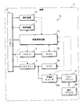
- FIG. 1 is a block diagram showing a configuration of an in-vehicle update system 1a according to the present embodiment.
- the power supply path is indicated by a thick solid line
- the signal transmission path is indicated by a broken line.
- 1 is a vehicle, and the vehicle 1 includes a battery 2, an IG relay 3, an ACC relay 4, a cigar socket 5, ECUs 6a and 6b, a display device 7, an operation device 8, and the like.
- the battery 2 is a device that stores electric power generated by an alternator (not shown) during engine operation of the vehicle 1, and can be configured using a battery such as a lead storage battery or a lithium ion battery.
- the battery 2 supplies the accumulated electric power to in-vehicle devices such as ECUs 6a and 6b mounted on the vehicle 1 while the engine of the vehicle 1 is stopped.
- the IG relay 3 is arranged in a power supply path from the battery 2 to an in-vehicle device such as the ECU 6a, and switches energization / cutoff of the power supply path.
- an in-vehicle device such as the ECU 6a
- switches energization / cutoff of the power supply path In FIG. 1, only one ECU 6a is connected to the IG relay 3.
- the IG relay 3 is switched between energization / interruption according to the state of an ignition switch (not shown) for performing an operation of switching the engine start of the vehicle 1 and the power supply state to the in-vehicle device.
- the IG relay 3 is switched so as to be in an energized state during the engine operation of the vehicle 1 and to be in a cut-off state when the engine is stopped.
- the ACC relay 4 is arranged in the power supply path from the battery 2 to the in-vehicle equipment such as the ECU 6b and the in-vehicle electrical components such as the cigar socket 5, and switches between energization / interruption of the power supply path.
- the present invention is not limited to this, and other in-vehicle devices or in-vehicle electrical components may be further connected.
- the ACC relay 4 is also switched between energization / interruption according to the state of the ignition switch of the vehicle 1. Switching between energization / cutoff of the IG relay 3 and switching between energization / cutoff of the ACC relay 4 are interlocked.
- the ACC relay 4 When the IG relay 3 is energized, the ACC relay 4 is energized, and the ACC relay 4 is When in the cut-off state, the IG relay 3 is cut off. However, it may exist when the IG relay 3 is in the cut-off state and the ACC relay 4 is in the energized state.
- the cigar socket 5 is a cigarette lighter socket provided near the driver's seat of the vehicle 1.
- the cigar socket 5 is not used for a cigar lighter but can be used as a connection part for supplying power to the outside, and in this case, it can also be called an accessory socket or a power socket.
- Various retrofit devices 99 can be connected to the cigar socket 5 via a power cable provided with a terminal called a so-called car plug. In the state where the retrofit device 99 is connected to the cigar socket 5, when the ACC relay 4 is switched to the energized state, power is supplied from the alternator of the vehicle 1 or the battery 2 to the retrofit device 99, and based on this power The retrofit device 99 can operate.
- the ECUs 6a and 6b are, for example, an ECU that controls the operation of the engine of the vehicle 1, an ECU that controls the locking / unlocking of the door, an ECU that controls the turning on / off of the light, an ECU that controls the operation of the airbag, and an ABS.
- Various ECUs such as an ECU that controls the operation of (Antilock Brake System) may be included.
- the ECUs 6a and 6b perform various processes by causing a CPU (Central Processing Unit) to execute a program stored in an internal memory or the like.
- the ECU 6 a is an ECU that can be an update process for updating a program stored in a memory or the like, and is connected to the battery 2 via the IG relay 3.
- the display device 7 is, for example, a liquid crystal display and displays a message or an image for the user of the vehicle 1.
- the operation device 8 is a device such as a push switch, a dial switch, or a touch panel disposed in the vicinity of the driver's seat of the vehicle 1 and is a device for receiving a user operation.
- the display device 7 and the operation device 8 may be shared with, for example, a car navigation device.
- the display device 7 and the operation device 8 are configured to receive power supply directly from the battery 2, but the present invention is not limited to this.
- the display device 7 and the operation device 8 may be configured to be connected to the battery 2 via the IG relay 3 or the ACC relay 4.
- the in-vehicle update system 1a includes an in-vehicle update device 10, a cigar relay 9, and the like.
- the in-vehicle update device 10 is a device that performs a process of updating a program or data (hereinafter simply referred to as a program) stored in a memory or the like of the ECU 6a.
- the in-vehicle update device 10 communicates with, for example, a server device outside the vehicle while the engine of the vehicle 1 is operating, inquires whether the program of the ECU 6a needs to be updated, and updates if necessary. Download the program for use and store it.
- the in-vehicle update device 10 When or before the engine of the vehicle 1 is stopped, the in-vehicle update device 10 displays a message notifying that the program of the ECU 6a needs to be updated on the display device 7 to inquire whether or not the update is possible.
- the device 8 accepts selection of whether or not to update from the user.
- the in-vehicle update device 10 stores the update program stored when the predetermined update timing is reached, for example, after a predetermined time has elapsed since the engine of the vehicle 1 is stopped. Update processing is performed by transmitting to the ECU 6a to be updated.
- the ECU 6 a to be updated in the present embodiment is connected to the battery 2 via the IG relay 3. While the engine of the vehicle 1 is stopped, the IG relay 3 is in a cut-off state, the electric power from the battery 2 is not supplied to the ECU 6a, and the ECU 6a cannot operate.
- the in-vehicle update device 10 can control switching of the IG relay 3 and the ACC relay 4, and when performing the update process of the ECU 6a, the IG relay 3 is switched to the energized state, thereby updating the object. ECU 6a in an operable state.
- the IG relay 3 and the ACC relay 4 are interlocked, and when the IG relay 3 is in an energized state, the ACC relay 4 is also in an energized state.
- the ACC relay 4 also switches to the energized state. Therefore, if the retrofit device 99 is connected to the cigar socket 5, when the in-vehicle update device 10 performs the update process, power is supplied from the battery 2 to the retrofit device 99.
- the retrofit device 99 is a device connected by the user according to his / her preference or necessity, and does not need to be operated for the update process of the ECU 6a, and does not need to supply the power of the battery 2 at all.
- a cigar relay 9 is provided in the power supply path from the ACC relay 4 to the cigar socket 5.
- the cigar relay 9 switches energization / cutoff of the power supply path in accordance with a control signal from the in-vehicle update device 10.
- the cigar relay 9 is arranged in the immediate vicinity of the cigar socket 5 and cuts off the power supply to the cigar socket 5.
- other in-vehicle devices such as the ECU 6b connected to the ACC relay 4 or in-vehicle electrical equipment The power supply to the product shall not be cut off.
- the cigar relay 9 is comprised using the latch relay which does not require electric power in order to maintain an energized state and a interruption
- the in-vehicle update device 10 completes the acquisition of the update program from the server device outside the vehicle, and starts the update process of the ECU 6a at a predetermined timing after the engine of the vehicle 1 is stopped. At this time, the in-vehicle update device 10 first performs control to switch the cigar relay 9 to the cutoff state. Next, the in-vehicle update device 10 performs control to switch the IG relay 3 and the ACC relay 4 to the energized state, and transmits a command to stop the operation to the ECU 6b that is not the target of the update process. Thereafter, the in-vehicle update device 10 performs the update process by transmitting the update program to the ECU 6a that is the target of the update process. After completion of the update process, the in-vehicle update device 10 performs control for switching the IG relay 3 and the ACC relay 4 to the cutoff state and performs control for switching the cigar relay 9 to the energized state.
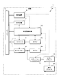
- FIG. 2 is a block diagram showing a configuration of the in-vehicle update device 10 according to the present embodiment.
- the in-vehicle updating apparatus 10 includes a processing unit 11, a storage unit 12, an in-vehicle communication unit 13, a control signal output unit 14, and the like.
- the processing unit 11 is configured using an arithmetic processing unit such as a CPU (Central Processing Unit) or an MPU (Micro-Processing Unit), and reads and executes a program (not shown) stored in the storage unit 12. Thus, various arithmetic processes are performed.
- CPU Central Processing Unit
- MPU Micro-Processing Unit
- the processing unit 11 is a process for downloading an update program for the ECU 6a from a server device outside the vehicle, a process for inquiring the user whether the update process is possible, a process for updating the program by transmitting the downloaded update program to the ECU 6a, etc. I do. Moreover, in this Embodiment, the process part 11 performs the switching control process of the IG relay 3, the ACC relay 4, and the cigar relay 9 at the time of performing an update process.
- the storage unit 12 is configured using a non-volatile memory element such as a flash memory or an EEPROM (Electrically Erasable Programmable Read Only Memory).
- the storage unit 12 stores a program executed by the processing unit 11 and data necessary for executing the program, and stores an update program 12a used for updating the ECU 6a.
- the storage unit 12 may store data generated in the course of processing by the processing unit 11.
- the in-vehicle communication unit 13 is connected to a communication line constituting an in-vehicle network provided in the vehicle 1 and transmits and receives data according to a communication protocol such as CAN (Controller Area Network).
- the in-vehicle communication unit 13 transmits information by converting the data provided from the processing unit 11 into an electric signal and outputs the signal to the communication line, and receives the data by sampling and acquiring the potential of the communication line.
- the received data is given to the processing unit 11. Accordingly, the in-vehicle update device 10 can transmit and receive data to and from the ECUs 6a and 6b, the display device 7, and the operation device 8 mounted on the vehicle 1.
- the control signal output unit 14 is connected to the IG relay 3, the ACC relay 4, and the cigar relay 9 via signal lines and the like, and receives a control signal for switching energization / cutoff of these relays according to an instruction from the processing unit 11. Output.
- the in-vehicle update device 10 directly performs relay switching control.
- the present invention is not limited to this, and a separate ECU that performs relay switching control is provided. It is good also as a structure which the vehicle-mounted update apparatus 10 instruct
- switching control of the IG relay 3 and the ACC relay 4 according to the operation of the ignition switch of the vehicle is not performed by the in-vehicle update device 10, but another ECU (not shown) that performs switching control of the relay. Is omitted).
- the update processing unit 21, the switching control unit 22, and the like are realized as software functional blocks by executing the program stored in the storage unit 12.
- the update processing unit 21 performs processing for updating a program stored in a storage unit of various in-vehicle devices (ECU 6a in the present embodiment) mounted on the vehicle 1.
- the update processing unit 21 communicates with a server device outside the vehicle while the engine of the vehicle 1 is operating, and performs a process of inquiring whether there is a program update for all on-vehicle devices that may be updated.
- the update processing unit 21 acquires an update program necessary for the update process from the server device and stores the update program in the storage unit 12.
- the update processing unit 21 reads the update program 12a stored in the storage unit 12 and becomes an object of the update process. Update processing is performed by transmitting to the device.
- the switching control unit 22 performs energization / interruption switching control of the IG relay 3, the ACC relay 4, and the cigar relay 9 when performing the update process by the update processing unit 21.
- the switching control unit 22 gives an instruction for energization / cutoff of each relay to the control signal output unit 14, and the control signal output unit 15 outputs a control signal for switching energization / cutoff of each relay in response thereto.
- the switching control unit 22 first performs control to switch the cigar relay 9 to the cutoff state.
- the switching control unit 22 performs control to switch the IG relay 3 and the ACC relay 4 to the energized state.
- the update processing unit 21 may perform a process of reducing power consumption by the ECU 6b by giving an instruction to stop the operation and shift to the sleep state to the ECU 6b that is not the target of the update process.
- the switching control unit 22 performs control to switch the IG relay 3 and the ACC relay 4 from the energized state to the disconnected state.
- the switching control unit 22 performs control to switch the cigar socket 5 from the shut-off state to the energized state. Thereby, the switching control part 22 can switch each relay to the state before the start of the update process by the update process part 21.
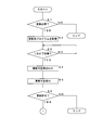
- 3 and 4 are flowcharts showing a procedure of processing performed by the in-vehicle update device 10 according to the present embodiment. Note that the processing shown in this flowchart starts from a state where the ignition switch of the vehicle 1 is on (that is, the engine of the vehicle 1 is operating). In this state, the IG relay 3, the ACC relay 4, and the cigar relay 9 of the vehicle 1 are in an energized state.
- the update processing unit 21 of the processing unit 11 of the in-vehicle update device 10 performs communication with a server device outside the vehicle using, for example, a wireless communication device mounted on the vehicle 1, and a program for the ECU 6 a mounted on the vehicle 1. It is determined whether or not the update process of the ECU 6a is necessary (step S1).
- the update processing unit 21 ends the process.
- the update processing unit 21 acquires an update program necessary for the update process from the server device (step S2), and stores the acquired update program in the storage unit 12. .
- the processing unit 11 determines whether or not the ignition switch of the vehicle 1 has been switched from the on state to the off state (step S3).
- the processing unit 11 waits until the ignition switch is switched to the off state.
- the processing unit 11 advances the processing to step S4. Note that the IG relay 3 and the ACC relay 4 are switched from the energized state to the cut-off state by switching the ignition switch to the off state.
- the update processing unit 21 of the processing unit 11 determines whether or not to permit the display device 7 to perform the update process of the ECU 6 by giving an instruction message display instruction to the display device 7 in the in-vehicle communication unit 13.
- a message to be inquired is displayed, and the user is inquired of whether or not update processing is possible (step S4).
- the message displayed at this time can be, for example, “ECU program needs to be updated. Are you sure you want to start the update from 11:00 pm today? (Yes / No)”.
- the update processing unit 21 accepts selection of whether or not the user can update the inquiry message displayed on the display device 7 by using the operation device 8 (step S5).
- the selection of whether or not update is accepted by the operation device 8 is transmitted to the in-vehicle update device 10 via the in-vehicle network, which is received by the in-vehicle communication unit 13 and given to the processing unit 11.
- the update processing unit 21 determines whether or not permission to perform the update process of the ECU 6a has been obtained based on the content received in step S5 (step S6). When the permission of the update process is not obtained (S6: NO), the update processing unit 21 ends the process without performing the update process.
- the update processing unit 21 determines whether or not a predetermined timing for performing the update process has been reached (step S7).
- a predetermined time for example, a predetermined time such as 11:00 pm, or a timing after two hours have elapsed since the ignition switch is switched to the off state can be employed.
- the update timing may be determined by the user.
- the update processing unit 21 stands by until the update timing is reached.
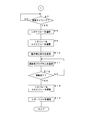
- the switching control unit 22 of the processing unit 11 switches the cigar relay 9 from the energized state to the disconnected state (step S8). Thereafter, the switching control unit 22 switches the IG relay 3 and the ACC relay 4 from the disconnected state to the energized state (step S9). Further, the update processing unit 21 of the processing unit 11 transmits an operation stop command to the ECU 6b that is not an update processing target in the in-vehicle communication unit 13 (step S10).
- the update processing unit 21 performs the update process by reading the update program 12a stored in the storage unit 12 and transmitting it to the ECU 6a to be updated by the in-vehicle communication unit 13 (step S11).
- the update processing unit 21 determines whether or not the transmission of the update program 12a is completed and the update process of the ECU 6a is completed (step S12).
- the update processing unit 21 returns the process to step S11 and continues to transmit the update program 12a.
- the switching control unit 22 switches the IG relay 3 and the ACC relay 4 from the energized state to the energized state (step S13). Thereafter, the switching control unit 22 switches the cigar relay 9 from the cut-off state to the energized state (step S14) and ends the process.
- the in-vehicle update device 10 installed in the vehicle 1 performs update processing of a program stored in the memory of the ECU 6a.
- the vehicle 1 is equipped with in-vehicle devices such as an ECU 6a that are subject to update processing and in-vehicle electrical components such as cigar sockets 5 that are not subject to update processing, and these are supplied with electric power from the battery 2 of the vehicle 1. Supplied.
- a cigar relay 9 is provided in the power supply path from the battery 2 to the cigar socket 5, and when the in-vehicle update device 10 performs the update process of the ECU 6a, the cigar relay 9 is controlled to be switched to a cut-off state.
- power is not supplied from the battery 2 to the cigar socket 5 (the retrofitted device 99 connected thereto) during the update process of the ECU 6a, so that a decrease in the stored power amount of the battery 2 can be suppressed.
- the in-vehicle update system 1a performs an update process of the ECU 6a when the engine of the vehicle 1 is stopped. Thereby, the update process of ECU6a can be performed safely, without affecting the driving
- the IG relay 3 is arranged in the power supply path from the battery 2 to the ECU 6a, and the ACC relay 4 is arranged in the power supply path from the battery 2 to the cigar relay 9.
- the in-vehicle update device 10 switches the IG relay 3 and the ACC relay 4 to the energized state when performing the update process. Thereby, the update process of ECU6a at the time of the engine stop of the vehicle 1 is realizable.
- the in-vehicle update system 1a has a vehicle-mounted electrical component that cuts off the power supply during the update process as a connection unit that can removably attach the retrofit device 99 via a feeder line or the like.
- the cigar socket 5 is used. Since the user of the vehicle 1 can connect an arbitrary retrofit device 99 to the cigar socket 5, the retrofit device 99 with excessive power consumption accompanying the operation is connected, and the battery is exhausted by the update process. May occur. By shutting off the power supply to the cigar socket 5 with the cigar relay 9, no matter what retrofit device 99 is connected to the cigar socket 5, the battery does not run out. Update processing can be performed.
- the in-vehicle update device 10 performs switching between energization / cutoff by the cigar relay 9. Since the in-vehicle update device 10 is a device that performs an update process such as the ECU 6a, it is possible to easily and appropriately switch the cigar relay 9 according to the update process.
- the dedicated in-vehicle update device 10 is provided in the system as a device for updating the program of the ECU 6a.
- the gateway device mounted on the vehicle 1 or any ECU may be configured to perform the update process.
- the in-vehicle update device 10 is configured to inquire the user of the vehicle 1 whether or not the update process is possible before performing the update process.
- the present invention is not limited to this.
- the in-vehicle update device 10 may be configured to perform the update process when the update timing is reached without inquiring whether the update process is possible.
- the system configuration shown in FIG. 1 is an example, and the present invention is not limited to this.
- the ECU 6 a to be updated may be connected to the battery 2 via the ACC relay 4 instead of being connected to the battery 2 via the IG relay 3.
- the cigar socket 5 may be connected to the battery 2 via the IG relay 3 instead of being connected to the battery 2 via the ACC relay 4.
- both the ECU 6a and the cigar socket 5 may be connected to the battery 2 via a common relay (IG relay 3 or ACC relay 4).
- the cigar relay 9 is arranged in the power supply path from the IG relay 3 or the ACC relay 4 to the cigar socket 5, and the electric power to the cigar socket 5 is set by turning off the cigar relay 9. Any configuration that cuts off the supply and does not cut off the supply of electric power to the ECU 6a may be used.
- the in-vehicle electrical component that cuts off the power supply during the update process is the cigar socket 5, but the present invention is not limited to this.
- the in-vehicle electrical component may be a USB standard connection unit to which power is supplied via the USB cable, to which the retrofit device 99 is detachably connected via a USB (UniversalUSBSerial Bus) cable, for example.
- a connection part having a configuration other than the cigar socket 5 and the USB standard connection part may be used.
- the in-vehicle electrical component is not limited to a connection part for connecting the retrofit device 99.
- the vehicle-mounted electrical component can be controlled by the user directly on / off of the power to the vehicle 1 by a switch operation or the like, but the vehicle-mounted update device 10 cannot give an operation stop command or the like by in-vehicle communication or the like. It may be a device.
- the in-vehicle update system 1a has a configuration in which the in-vehicle update device 10 that performs update processing of the ECU 6a performs switching control of energization / cutoff of the cigar relay 9, but is not limited thereto.
- FIG. 5 is a block diagram illustrating a configuration of the in-vehicle update system 1a according to the first modification.
- the operation device 8 performs energization / cutoff switching control of the cigar relay 9.
- the operation device 8 performs a process of accepting selection of whether or not update is possible from the user in response to an inquiry as to whether or not to perform the update process by the in-vehicle update device 10.
- the controller device 8 according to the first modification performs a process of switching the cigar relay 9 from the energized state to the cut-off state when receiving a selection for permitting the update process. Further, the operation device 8 shuts off the cigar relay 9 when, for example, the ignition switch of the vehicle 1 is switched from an off state to an on state, or when an update processing completion notification is given from the in-vehicle update device 10. The process to switch from to the energized state is performed.
- the switching control of energization / cutoff of the cigar relay 9 may be performed by a device other than the in-vehicle update device 10 or the operation device 8.
- a device that performs switching control of the IG relay 3 and the ACC relay 4 according to switching of the ignition switch of the vehicle 1 performs switching control of energization / cutoff of the cigar relay 9 according to an instruction from the in-vehicle update device 10 can do.
- FIG. 6 is a block diagram illustrating a configuration of the in-vehicle update system 1a according to the second modification.
- the in-vehicle update system 1a according to the second modification uses the semiconductor fuse 109 as the cigar relay 9.
- the semiconductor fuse 109 controls a semiconductor element such as a MOSFET (Metal Oxide Semiconductor Field Effect Transistor) disposed in the power supply path and performs switching control of energization / cutoff of the semiconductor element by detecting the amount of current flowing through the semiconductor element.
- IC Integrated Circuit
- the semiconductor fuse 109 can perform switching control of energization / cutoff of the semiconductor element in accordance with a switching signal of energization / cutoff given from the in-vehicle update device 10.
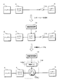
- FIG. 7 is a schematic diagram for explaining the semiconductor fuse 109 according to the second modified example, and shows a power supply path from the battery 2 of the vehicle 1 to the cigar socket 5 through the ACC relay 4. .
- the upper part of FIG. 7 illustrates the configuration of a conventional vehicle.
- the fuse 110 is provided in the power supply path between the ACC relay 4 and the cigar socket 5.
- the fuse 110 is blown by the overcurrent flowing and interrupts the power supply path, thereby preventing the overcurrent from flowing to the retrofit device 99 connected to the cigar socket 5.
- FIG. 7 shows the configuration of the in-vehicle update system 1a according to the above-described embodiment.
- a cigar relay 9 is added between the ACC relay 4 and the fuse 110 with respect to the conventional configuration, and the in-vehicle update device 10 performs energization / interruption switching control of the cigar relay 9. Do. If an overcurrent flows through the fuse 110 while the cigar relay 9 is energized, the fuse 110 is blown and the power supply path is interrupted.
- the power is supplied from the battery 2 to the retrofit device 99 connected to the cigar socket 5 during the update process by switching the cigar relay 9 to the cut-off state. To prevent that.
- the in-vehicle update system 1a according to the modified example 2 has a configuration in which the cigar relay 9 and the fuse 110 in the system configuration shown in the middle stage of FIG.
- the semiconductor fuse 109 includes a MOSFET 109a arranged in the power supply path between the ACC relay 4 and the cigar socket 5, and a control IC 109b that performs switching control of energization / cutoff of the MOSFET 109a.
- the control IC 109b detects the current flowing through the MOSFET 109a, and switches the MOSFET 109a from the energized state to the cut-off state when, for example, the detected current amount exceeds a threshold value.
- control IC 109b switches the MOSFET 109a from the energized state to the cut-off state in response to the cut-off command given from the in-vehicle update device 10. Therefore, the MOSFET 109a is in a cut-off state when the control IC 109b detects an overcurrent and when the in-vehicle update device 10 outputs a cut-off command, and is in an energized state in other cases.
- the in-vehicle update system 1a is configured to use the semiconductor fuse 109 as the cigar relay 9.
- the semiconductor fuse 109 is a circuit element having both the function of the fuse 110 provided in the power supply path from the ACC relay 4 to the cigar socket 5 and the function of the cigar relay 9, so that it is not necessary to provide the fuse 110, and the in-vehicle
- the number of parts such as circuit elements constituting the update system 1a can be reduced.
Landscapes
- Engineering & Computer Science (AREA)
- Theoretical Computer Science (AREA)
- General Engineering & Computer Science (AREA)
- Software Systems (AREA)
- General Physics & Mathematics (AREA)
- Physics & Mathematics (AREA)
- Mechanical Engineering (AREA)
- Computer Security & Cryptography (AREA)
- Power Engineering (AREA)
- Quality & Reliability (AREA)
- Automation & Control Theory (AREA)
- Stored Programmes (AREA)
- Charge And Discharge Circuits For Batteries Or The Like (AREA)
Priority Applications (3)
| Application Number | Priority Date | Filing Date | Title |
|---|---|---|---|
| CN201780062347.0A CN109844720A (zh) | 2016-10-31 | 2017-10-27 | 车载更新系统及车载更新装置 |
| US16/344,898 US20190294431A1 (en) | 2016-10-31 | 2017-10-27 | On-board update system and on-board update device |
| DE112017005500.8T DE112017005500T5 (de) | 2016-10-31 | 2017-10-27 | Bordeigenes Aktualisierungssystem und bordeigene Aktualisierungsvorrichtung |
Applications Claiming Priority (2)
| Application Number | Priority Date | Filing Date | Title |
|---|---|---|---|
| JP2016213359A JP6690500B2 (ja) | 2016-10-31 | 2016-10-31 | 車載更新システム及び車載更新装置 |
| JP2016-213359 | 2016-10-31 |
Publications (1)
| Publication Number | Publication Date |
|---|---|
| WO2018079697A1 true WO2018079697A1 (ja) | 2018-05-03 |
Family
ID=62023712
Family Applications (1)
| Application Number | Title | Priority Date | Filing Date |
|---|---|---|---|
| PCT/JP2017/038836 Ceased WO2018079697A1 (ja) | 2016-10-31 | 2017-10-27 | 車載更新システム及び車載更新装置 |
Country Status (5)
| Country | Link |
|---|---|
| US (1) | US20190294431A1 (enExample) |
| JP (1) | JP6690500B2 (enExample) |
| CN (1) | CN109844720A (enExample) |
| DE (1) | DE112017005500T5 (enExample) |
| WO (1) | WO2018079697A1 (enExample) |
Families Citing this family (10)
| Publication number | Priority date | Publication date | Assignee | Title |
|---|---|---|---|---|
| JP6665728B2 (ja) * | 2016-08-05 | 2020-03-13 | 株式会社オートネットワーク技術研究所 | 車載更新装置、車載更新システム及び通信装置の更新方法 |
| JP7105604B2 (ja) * | 2018-05-11 | 2022-07-25 | ヤマハ発動機株式会社 | 船外機 |
| JP6742381B2 (ja) * | 2018-10-15 | 2020-08-19 | 本田技研工業株式会社 | 車両制御装置、車両制御方法、およびプログラム |
| JP7192415B2 (ja) * | 2018-11-06 | 2022-12-20 | 株式会社オートネットワーク技術研究所 | プログラム更新システム及び更新処理プログラム |
| JP7437280B2 (ja) * | 2020-09-28 | 2024-02-22 | 株式会社Subaru | 車両 |
| JP7526066B2 (ja) * | 2020-09-28 | 2024-07-31 | 株式会社Subaru | 車両 |
| KR20220132864A (ko) * | 2021-03-24 | 2022-10-04 | 현대자동차주식회사 | 차량 및 차량 제어 방법 |
| WO2023095535A1 (ja) * | 2021-11-26 | 2023-06-01 | 株式会社オートネットワーク技術研究所 | 遮断装置 |
| JP7579309B2 (ja) * | 2022-09-28 | 2024-11-07 | 本田技研工業株式会社 | 制御装置、及び、制御方法 |
| CN119853262A (zh) * | 2025-03-18 | 2025-04-18 | 深圳市立顺电通科技有限公司 | 一种双电源自动切换保护电路 |
Citations (5)
| Publication number | Priority date | Publication date | Assignee | Title |
|---|---|---|---|---|
| JP2013151222A (ja) * | 2012-01-25 | 2013-08-08 | Toyota Motor Corp | 充電通信装置、充電通信方法、プログラム、媒体 |
| JP2013151817A (ja) * | 2012-01-25 | 2013-08-08 | Toyota Motor Corp | 電力制御システム |
| JP2014024444A (ja) * | 2012-07-26 | 2014-02-06 | Nippon Seiki Co Ltd | 電力供給制御装置、計器装置 |
| JP2016060388A (ja) * | 2014-09-18 | 2016-04-25 | 株式会社オートネットワーク技術研究所 | プログラム送信システム及びプログラム送信装置 |
| JP2016170740A (ja) * | 2015-03-16 | 2016-09-23 | 日立オートモティブシステムズ株式会社 | ソフト更新装置、ソフト更新方法 |
Family Cites Families (6)
| Publication number | Priority date | Publication date | Assignee | Title |
|---|---|---|---|---|
| JP3373664B2 (ja) * | 1994-08-05 | 2003-02-04 | マツダ株式会社 | 車両用電源供給装置 |
| JP4242405B2 (ja) * | 2006-09-15 | 2009-03-25 | 三菱電機株式会社 | 車載電子制御装置 |
| JP5013833B2 (ja) * | 2006-12-05 | 2012-08-29 | 株式会社日立製作所 | 家庭電池制御装置、家庭電池制御システム、車載電池制御システム、家庭電池制御方法及び車載電池制御方法 |
| JP2011070287A (ja) | 2009-09-24 | 2011-04-07 | Toyota Motor Corp | プログラム更新装置、センタ及びプログラム更新システム |
| EP3277546B1 (en) * | 2015-03-30 | 2022-06-22 | Parallel Wireless Inc. | Power management for vehicle-mounted base station |
| JP2018095066A (ja) * | 2016-12-13 | 2018-06-21 | 株式会社オートネットワーク技術研究所 | 車載電力供給システム、リレーボックス及びリレー制御装置 |
-
2016
- 2016-10-31 JP JP2016213359A patent/JP6690500B2/ja not_active Expired - Fee Related
-
2017
- 2017-10-27 DE DE112017005500.8T patent/DE112017005500T5/de not_active Withdrawn
- 2017-10-27 US US16/344,898 patent/US20190294431A1/en not_active Abandoned
- 2017-10-27 WO PCT/JP2017/038836 patent/WO2018079697A1/ja not_active Ceased
- 2017-10-27 CN CN201780062347.0A patent/CN109844720A/zh active Pending
Patent Citations (5)
| Publication number | Priority date | Publication date | Assignee | Title |
|---|---|---|---|---|
| JP2013151222A (ja) * | 2012-01-25 | 2013-08-08 | Toyota Motor Corp | 充電通信装置、充電通信方法、プログラム、媒体 |
| JP2013151817A (ja) * | 2012-01-25 | 2013-08-08 | Toyota Motor Corp | 電力制御システム |
| JP2014024444A (ja) * | 2012-07-26 | 2014-02-06 | Nippon Seiki Co Ltd | 電力供給制御装置、計器装置 |
| JP2016060388A (ja) * | 2014-09-18 | 2016-04-25 | 株式会社オートネットワーク技術研究所 | プログラム送信システム及びプログラム送信装置 |
| JP2016170740A (ja) * | 2015-03-16 | 2016-09-23 | 日立オートモティブシステムズ株式会社 | ソフト更新装置、ソフト更新方法 |
Also Published As
| Publication number | Publication date |
|---|---|
| JP6690500B2 (ja) | 2020-04-28 |
| US20190294431A1 (en) | 2019-09-26 |
| CN109844720A (zh) | 2019-06-04 |
| DE112017005500T5 (de) | 2019-09-12 |
| JP2018074798A (ja) | 2018-05-10 |
Similar Documents
| Publication | Publication Date | Title |
|---|---|---|
| JP6690500B2 (ja) | 車載更新システム及び車載更新装置 | |
| JP6642393B2 (ja) | 車載更新システム | |
| CN108602474A (zh) | 车载电力供给系统、继电器箱及继电器控制装置 | |
| JP6573500B2 (ja) | ソフトウェア更新システム | |
| US9541937B2 (en) | In-vehicle communication system | |
| JP6122412B2 (ja) | 車両用電源ボックス装置 | |
| JP2021151871A (ja) | 車両用制御装置 | |
| JP6116535B2 (ja) | 車両用電源ボックス装置 | |
| JP7131372B2 (ja) | 車載通信装置 | |
| CN111247038A (zh) | 程序更新装置、程序更新系统及程序更新方法 | |
| US11416237B2 (en) | Control apparatus, control method, and computer program | |
| CN106105156A (zh) | 机动车在停车阶段期间的遥控 | |
| CN104918829A (zh) | 车载电源控制器 | |
| US12065092B2 (en) | Vehicle control apparatus and power source supply circuit | |
| JP6840712B2 (ja) | 車載システム | |
| JP2018074798A5 (enExample) | ||
| CN112136106B (zh) | 电子控制装置以及存储介质 | |
| JP2016124455A (ja) | 車載中継装置及び中継方法 | |
| WO2018079280A1 (ja) | 車載更新システム及び車載更新装置 | |
| WO2018198595A1 (ja) | 車載電力供給システム、車載制御装置及び電力供給制御方法 | |
| JP2016013754A (ja) | 車両用電装機器接続システム | |
| JP7670639B2 (ja) | 車両 | |
| JP2024047989A (ja) | 車載装置、情報処理方法及び車載システム | |
| JP2023130046A (ja) | 給電制御装置、給電制御システム及び給電制御方法 | |
| JPH05146079A (ja) | 電源分配装置 |
Legal Events
| Date | Code | Title | Description |
|---|---|---|---|
| 121 | Ep: the epo has been informed by wipo that ep was designated in this application |
Ref document number: 17865464 Country of ref document: EP Kind code of ref document: A1 |
|
| 122 | Ep: pct application non-entry in european phase |
Ref document number: 17865464 Country of ref document: EP Kind code of ref document: A1 |