WO2018079360A1 - 電池制御装置、電池パック、及び電池システム - Google Patents
電池制御装置、電池パック、及び電池システム Download PDFInfo
- Publication number
- WO2018079360A1 WO2018079360A1 PCT/JP2017/037627 JP2017037627W WO2018079360A1 WO 2018079360 A1 WO2018079360 A1 WO 2018079360A1 JP 2017037627 W JP2017037627 W JP 2017037627W WO 2018079360 A1 WO2018079360 A1 WO 2018079360A1
- Authority
- WO
- WIPO (PCT)
- Prior art keywords
- battery
- battery cell
- temperature
- temperature information
- vehicle
- Prior art date
- Legal status (The legal status is an assumption and is not a legal conclusion. Google has not performed a legal analysis and makes no representation as to the accuracy of the status listed.)
- Ceased
Links
Images


Classifications
-
- B—PERFORMING OPERATIONS; TRANSPORTING
- B60—VEHICLES IN GENERAL
- B60L—PROPULSION OF ELECTRICALLY-PROPELLED VEHICLES; SUPPLYING ELECTRIC POWER FOR AUXILIARY EQUIPMENT OF ELECTRICALLY-PROPELLED VEHICLES; ELECTRODYNAMIC BRAKE SYSTEMS FOR VEHICLES IN GENERAL; MAGNETIC SUSPENSION OR LEVITATION FOR VEHICLES; MONITORING OPERATING VARIABLES OF ELECTRICALLY-PROPELLED VEHICLES; ELECTRIC SAFETY DEVICES FOR ELECTRICALLY-PROPELLED VEHICLES
- B60L50/00—Electric propulsion with power supplied within the vehicle
- B60L50/50—Electric propulsion with power supplied within the vehicle using propulsion power supplied by batteries or fuel cells
- B60L50/60—Electric propulsion with power supplied within the vehicle using propulsion power supplied by batteries or fuel cells using power supplied by batteries
-
- H—ELECTRICITY
- H01—ELECTRIC ELEMENTS
- H01M—PROCESSES OR MEANS, e.g. BATTERIES, FOR THE DIRECT CONVERSION OF CHEMICAL ENERGY INTO ELECTRICAL ENERGY
- H01M10/00—Secondary cells; Manufacture thereof
- H01M10/42—Methods or arrangements for servicing or maintenance of secondary cells or secondary half-cells
- H01M10/48—Accumulators combined with arrangements for measuring, testing or indicating the condition of cells, e.g. the level or density of the electrolyte
-
- H—ELECTRICITY
- H02—GENERATION; CONVERSION OR DISTRIBUTION OF ELECTRIC POWER
- H02J—ELECTRIC POWER NETWORKS; CIRCUIT ARRANGEMENTS OR SYSTEMS FOR SUPPLYING OR DISTRIBUTING ELECTRIC POWER; SYSTEMS FOR STORING ELECTRIC ENERGY
- H02J7/00—Circuit arrangements for charging or discharging batteries or for supplying loads from batteries
-
- Y—GENERAL TAGGING OF NEW TECHNOLOGICAL DEVELOPMENTS; GENERAL TAGGING OF CROSS-SECTIONAL TECHNOLOGIES SPANNING OVER SEVERAL SECTIONS OF THE IPC; TECHNICAL SUBJECTS COVERED BY FORMER USPC CROSS-REFERENCE ART COLLECTIONS [XRACs] AND DIGESTS
- Y02—TECHNOLOGIES OR APPLICATIONS FOR MITIGATION OR ADAPTATION AGAINST CLIMATE CHANGE
- Y02E—REDUCTION OF GREENHOUSE GAS [GHG] EMISSIONS, RELATED TO ENERGY GENERATION, TRANSMISSION OR DISTRIBUTION
- Y02E60/00—Enabling technologies; Technologies with a potential or indirect contribution to GHG emissions mitigation
- Y02E60/10—Energy storage using batteries
-
- Y—GENERAL TAGGING OF NEW TECHNOLOGICAL DEVELOPMENTS; GENERAL TAGGING OF CROSS-SECTIONAL TECHNOLOGIES SPANNING OVER SEVERAL SECTIONS OF THE IPC; TECHNICAL SUBJECTS COVERED BY FORMER USPC CROSS-REFERENCE ART COLLECTIONS [XRACs] AND DIGESTS
- Y02—TECHNOLOGIES OR APPLICATIONS FOR MITIGATION OR ADAPTATION AGAINST CLIMATE CHANGE
- Y02T—CLIMATE CHANGE MITIGATION TECHNOLOGIES RELATED TO TRANSPORTATION
- Y02T10/00—Road transport of goods or passengers
- Y02T10/60—Other road transportation technologies with climate change mitigation effect
- Y02T10/70—Energy storage systems for electromobility, e.g. batteries
Definitions
- the present invention relates to a battery control system, a battery pack, and a battery system.
- a lithium ion secondary battery may generate a “high load resistance rise” in which the resistance significantly increases.
- the battery management system Battery Management Management System, hereinafter referred to as BMS
- BMS Battery Management Management System
- the battery load is appropriately limited based on the index.
- a blank period for the control calculation occurs while the BMS is stopped, it is necessary to appropriately limit the battery load based on the battery load index calculated in consideration of the blank period for the control calculation, that is, the BMS stop time immediately after the restart. .
- Patent Document 1 describes the content of calculating the battery state index after the BMS stop period by periodically measuring the battery state during the BMS stop period.
- Patent Document 1 In order to suppress an increase in the high load resistance, it is necessary to appropriately limit the battery load after starting BMS in consideration of the blank period of control calculation while the BMS is stopped. In addition, the technique disclosed in Patent Document 1 has a problem that standby current increases because there are elements that are operating even when the vehicle is stopped. In addition, when the RTC is mounted, there is a risk that the component cost may increase, or there is a possibility that appropriate current limitation cannot be performed when the RTC fails.
- the battery control device limits the input / output power of the battery cell using temperature information of the battery cell and temperature information different from the temperature information of the battery cell.
- the present invention it is possible to limit the input / output power of the BMS stop time even in a situation where the RTC cannot be used (for example, a situation where the RTC is not installed or a situation where the RTC has failed).
- the battery load index immediately after the restart of BMS can be calculated even in a situation where the RTC is not installed or in a situation where the RTC has failed.
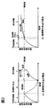
- FIG. 1 is a diagram showing a battery load index when the initial value at the time of restarting BMS is set to zero.
- FIG. 2 is a diagram showing battery load index transition when the initial value at the time of restarting BMS is set to the previous value.
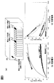
- FIG. 3 is a diagram illustrating a temperature change of the battery pack due to charging / discharging.
- FIG. 4 is a diagram showing an outline of the allowable power calculation block.
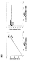
- FIG. 5 is a diagram illustrating a BMS stop time estimation result in the first example.
- FIG. 6 is a diagram illustrating a BMS stop time estimation result in the second example.
- the first embodiment will be described.
- the vehicle BMS stores the battery load index when the vehicle is stopped (during the process when the vehicle was stopped last time), and the battery load index is stored as the vehicle rest time (when the vehicle is restarted). It is necessary to calculate the attenuation in accordance with the elapsed time from when the vehicle stops to when the vehicle restarts.
- BMS boards with severe cost restrictions and standby power restrictions do not include an RTC that acquires time information, so vehicle downtime cannot be acquired, and after vehicle restart (the period after vehicle restart) It is very difficult to calculate a correct battery load index.
- FIGS. 1A and 1B are diagrams for explaining data processing after the battery load index at the time of vehicle restart is reset to zero.
- the processing in the BMS can be roughly divided into a previous operation period A, a suspension period B, and a current operation period C.
- the true value during the current operation period C is a solid line
- the battery load index obtained by resetting to 0 is represented by a two-dot chain as an apparent value.
- the true value and the apparent value are substantially the same value.
- FIGS. 2A and 2B are diagrams for explaining the subsequent data processing by substituting the battery load index when the vehicle is stopped again.
- the pause period B is a short period
- the battery since the battery does not enter a steady state, when the previous value is substituted as in this method, the true value and the apparent value are substantially the same value. It becomes.
- the suspension period B is long
- the battery is in a steady state. Therefore, when measures are taken by substituting the previous value as in this method, the apparent value is greater than the true value. It will deviate in the direction of increasing greatly. Therefore, when this method is adopted and the vehicle is rested for a long time as shown in FIG. 2 (a), the apparent value of the battery load index after restarting the vehicle becomes larger than the true value, so it is restricted more than necessary. May be overloaded.
- the battery load index when the vehicle is restarted is reset to 0, or the battery load index when the vehicle is stopped last time is substituted.
- the power cannot be appropriately limited in both cases.
- FIG. 3A schematically shows the battery pack 100.
- the battery pack 100 includes a battery pack center temperature sensor 200, a battery pack end side temperature sensor 210, and a battery pack housing internal temperature sensor 220.
- 3 (b) shows the correlation between the charge / discharge time and the battery temperature
- FIG. 3 (c) shows the time dependence of the battery pack end temperature and the battery pack center temperature after the charge / discharge is stopped for a predetermined time. It is a figure. As shown in FIG.
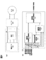
- FIG. 4 is a diagram for explaining the first embodiment of the battery management system according to the present invention.
- FIG. 4A shows the battery system 10.
- the battery system 10 includes a battery pack 100 and a BMS 110 connected to the battery pack 100 and controlling the battery pack.
- This battery system 10 is connected to an inverter 120, and this inverter 120 is connected to a motor 130 to constitute a vehicle drive system.
- FIG. 4B is an enlarged control block diagram of the BMS 110.
- Current information, voltage information, temperature information, charging rate information, and resistivity information acquired from the battery cells of the battery pack 100 via a cell controller (not shown) are input to the BMS 110.
- the BMS 110 includes a pre-restriction allowable power calculation unit 111, a battery load index calculation unit 112, a restriction rate calculation unit 113, and a post-restriction allowable power calculation unit 114.
- the pre-limit allowable power calculation unit 111 is a block that calculates allowable power that can be charged and discharged within the upper and lower limit voltage set value range of the battery.
- the battery load index calculation unit 112 is a block that calculates a battery load index indicating the magnitude and continuity of the battery load.
- the limiting rate calculation unit 113 is a block that calculates the limiting rate based on the battery load index.
- the post-restriction allowable power calculation unit 114 is a block that calculates the post-restriction allowable power by multiplying the pre-restriction allowable power by the restriction rate.
- the pre-limit allowable power calculation unit 111 and the battery load index calculation unit 112 are input with current information, voltage information, temperature information, charge rate information, and resistivity information acquired via a cell controller (not shown), respectively. Calculate the aforementioned control parameters. From the battery load index calculated by the battery load index calculation unit 112, voltage information, temperature information, and charge rate information, the limit rate calculation unit 113 calculates a limit rate. Then, the post-restriction allowable power calculation unit 114 calculates the post-control allowable power value from the parameters calculated by the pre-restriction allowable power calculation unit 111 and the limiting rate.
- the temperature difference ( ⁇ T) between the pack center temperature (T center ) and the environmental temperature (T amb ) immediately after the charge / discharge pause (t 0 ) is exponentially attenuated with the time constant ⁇ .
- equation (2) the elapsed time (t rest ) can be obtained as in equation (2).
- Formula (2) is the basic formula for estimating vehicle downtime in the present invention.
- the temperature input of Equation (2) is the temperature sensor error (drift error, offset error between sensors), the temperature sensor resolution, the vehicle paused
- T amb environmental temperature
- the following constraint conditions must be satisfied.
- the denominator component in the log function is a positive value
- the numerator component in the log function is a positive value
- the numerator component is larger than the denominator component in the log function (D ) Elapsed time (t rest ) becomes 0 or more Therefore, it is preferable to calculate by satisfying the above constraint condition with respect to the above equation (2).
- the vehicle downtime changes substantially on the true value line in the section of 10000 sec or less. From this result, the vehicle downtime can be estimated quantitatively from the temperature information. Then, from FIG. 5 (b), in the time t 0 and the temperature difference is large 1000sec or more sections of the battery pack at time t 1, the estimated value ratio of the vehicle downtime was confirmed to remain at the reference line. Furthermore, in the section where the temperature difference between the battery packs at time t 0 and time t 1 is small and is 1000 sec or less, the fluctuation range of the estimated value ratio of the vehicle downtime is large and exceeds the reference line. This calculation is performed by the battery load index calculation unit 112.
- the present invention it is possible to estimate the elapsed time from when the vehicle is stopped with high accuracy in a situation where the RTC cannot be used, so that the battery load index can be calculated with high accuracy. Particularly in the region of 1000 sec or more, the time from when the vehicle stops can be estimated with high accuracy, and the battery load index can be calculated particularly with high accuracy.
- the time from when the vehicle is stopped is estimated using the difference between the temperature of the battery cell when the vehicle is stopped and the environmental temperature.
- another temperature can be used.
- the temperature of the battery cell when the vehicle is stopped and the temperature of the battery cell when the vehicle is started may be used to estimate the elapsed time since the vehicle stopped.
- a temperature sensor for measuring the environmental temperature is not required, so that the battery pack can be simplified.
- the temperature of the battery cell when the vehicle is stopped and the temperature information inside the battery pack housing in which the battery cell is stored may be used. By adopting such a configuration, this control can be completed as a product of one battery pack.
- the temperature information of the battery cell at the time of starting the vehicle and the temperature information inside the case in which the battery cell is stored are used in this embodiment, the temperature information of the battery cell at the time of starting the vehicle and the case in which the battery cell is stored Input / output power of the battery cell when the difference from the internal temperature information is larger than a predetermined value and the temperature information of the battery cell is higher than the temperature information inside the housing in which the battery cell is stored Limit. With such a configuration, even if there is a large difference between the temperature inside the housing and the temperature of the battery cell, it is possible to reliably limit the allowable power and provide a safe battery pack. It becomes.
- ⁇ T offset, margin with respect to variations in offset error between sensors
- t rest, margin vehicle rest time margin
- ⁇ T drift, margin dead margin
- the limiting rate calculation unit 113 calculates the limiting rate with high accuracy from the battery load index, voltage information, temperature information, and charging rate information calculated with high accuracy in a state where the RTC cannot be used. Since the allowable power can be calculated by the post-restricted allowable power calculation unit 114 using this limiting rate, it is possible to limit the input / output power with high accuracy even if the RTC is not used.
- the first embodiment is briefly summarized as above.
- the battery control device described in the present embodiment estimates the elapsed time from when the vehicle is stopped by using temperature information of the battery cell and temperature information (for example, environmental temperature) different from the temperature information of the battery cell. The input / output power was limited.
- the battery load index can be calculated with high accuracy even in a situation where the RTC cannot be used (for example, a situation where the RTC is not installed or a situation where the RTC has failed).
- the input / output power can be limited even in a situation where the RTC that can limit the output power cannot be used (for example, a situation where the RTC is not mounted or a situation where the RTC has failed).
- the battery control device described in the present embodiment uses the battery cell temperature information at the time of starting the vehicle as the battery cell temperature information.
- a temperature sensor for measuring the environmental temperature is not required, so that the battery pack can be simplified.
- the battery control device described in the present embodiment uses temperature information inside the housing in which the battery cell is stored as temperature information different from the temperature of the battery cell. By adopting such a configuration, this control can be completed as a product of one battery pack.
- the battery control device described in the present embodiment is a case where the difference between the temperature information of the battery cell at the time of starting the vehicle and the temperature information inside the housing in which the battery cell is stored is larger than a predetermined value, and When the temperature information of the battery cell is higher than the temperature information inside the housing in which the battery cell is stored, the input / output power of the battery cell is limited. With such a configuration, even if there is a large difference between the temperature inside the housing and the temperature of the battery cell, it is possible to reliably limit the allowable power and provide a safe battery pack. It becomes.
- the battery control device described in the present embodiment uses the temperature information of the battery cell when the vehicle is stopped as temperature information different from the temperature information of the battery cell.
- the battery control device according to the present embodiment is configured so that the difference between the temperature information inside the housing in which the battery cell is stored and the temperature information of the battery cell when the vehicle is stopped is greater than a predetermined value. Limit the input / output power of the.
- Second Embodiment a second embodiment will be described. Since the actual BMS 110 may not be able to acquire environmental temperature information that is not affected by the heat generated by charging / discharging the battery, in this embodiment, the environmental temperature information is acquired from the host system. That is, the BMS in the present embodiment acquires the environmental temperature (T amb) is foil, using a temperature information of the battery pack end instead of the ambient temperature (T amb). The calculation conditions were the same as those in the first example.
- FIG. 6A shows a comparison between the true value of the vehicle downtime estimated using this embodiment and the estimated value
- FIG. 6B shows the ratio of the vehicle downtime estimated value to the true value.
- the estimated value of the vehicle downtime using the pack end temperature (T end ) is similar to the estimated value of the vehicle downtime using the environment temperature (T amb ). It has changed. With such a configuration, it is possible to limit input / output power with high accuracy only by providing two temperature sensors in one battery pack.
- the vehicle downtime is estimated using the battery pack center temperature (T center ) and the battery pack end temperature (T end ), so that there is no element such as RTC for acquiring time information. Reliable suppression of increase in high load resistance can be realized.
- Battery system 100 Battery pack 110 BMS 111 Allowable power calculation unit before limit 112 Battery load index calculation unit 113 Limit rate calculation unit 114 Allowable power calculation unit after limit 120 Inverter 130 Motor 200 Battery pack center temperature sensor 210 Battery pack end temperature sensor 220 Battery pack housing internal temperature Sensor
Landscapes
- Engineering & Computer Science (AREA)
- Power Engineering (AREA)
- Manufacturing & Machinery (AREA)
- Chemical & Material Sciences (AREA)
- Chemical Kinetics & Catalysis (AREA)
- Electrochemistry (AREA)
- General Chemical & Material Sciences (AREA)
- Life Sciences & Earth Sciences (AREA)
- Sustainable Development (AREA)
- Sustainable Energy (AREA)
- Transportation (AREA)
- Mechanical Engineering (AREA)
- Secondary Cells (AREA)
- Electric Propulsion And Braking For Vehicles (AREA)
- Charge And Discharge Circuits For Batteries Or The Like (AREA)
Abstract
電池パック及び電池制御装置において、RTCが使用できない状況でも入出力電力の制限を高精度に行うことを課題とする。 本発明に記載の電池制御装置は、電池セルの温度情報と、電池セルの温度情報とは異なる温度情報を用いて、電池セルの入出力電力を制限する。
Description
本発明は、電池制御システム、電池パック、及び電池システムに関する。
リチウムイオン二次電池は短期間で継続的に大きな負荷を掛けられると、抵抗が著しく上昇する「高負荷抵抗上昇」が発生することがある。 この「高負荷抵抗上昇」を抑制するため、電池管理システム(Battery Management System、以下BMS)は、直近での電池負荷の大きさと継続性を示す電池負荷指標を常に演算し、演算された電池負荷指標に基づき電池負荷を適切に制限している。しかし、BMS停止中は制御演算の空白期間が生じるため、再始動直後は制御演算の空白期間、即ちBMS停止時間を考慮して演算した電池負荷指標に基づき電池負荷を適切に制限する必要がある。
従来のBMS停止時間を算出する技術として、リアルタイムクロック(Real Time Clock、以下RTC)を用いる方式が一般的である。また、BMS停止期間も定期的に電池状態測定を実施することで、BMS停止期間後の電池の状態指標を演算する内容が特許文献1に記載されている。
高負荷抵抗上昇を抑制するためには、BMS停止中における制御演算の空白期間を考慮して、BMS起動後の電池負荷を適切に制限する必要があるが、RTCから車両休止時間を演算する方式や前記の特許文献1に開示された技術は、車両休止中も稼働している素子があるため、待機電流が増加する課題がある。また、RTCを搭載する場合は部品コストが増加してしまう恐れや、RTCが故障した時に適切な電流制限を実施できない恐れがある。
上記課題を解決するため、本発明に記載の電池制御装置は、電池セルの温度情報と、電池セルの温度情報とは異なる温度情報を用いて、電池セルの入出力電力を制限する。
本発明によれば、BMS停止時間を、RTCが使用できない状況(例えばRTCが搭載されていない状況、またはRTCが故障した状況)でも入出力電力の制限が可能となる。また、他の目的としてBMS再始動直後の電池負荷指標を、RTCが搭載されていない状況、またはRTCが故障した状況でも演算出来る。
《第1の実施例》
以下、図を参照して本発明を実施するための形態について説明する。
以下、図を参照して本発明を実施するための形態について説明する。
第1の実施例について説明する。
車両用BMSは、車両停止時(前回車両停止した際の処理時)の電池負荷指標を記憶して車両再始動時(車両を再始動した際の処理時)は電池負荷指標を車両休止時間(車両停止時から車両再始動時までの経過時間)に応じて減衰演算する必要がある。しかしながら、コスト上の制約や待機電力の制約が厳しいBMS基板では時刻情報を取得するRTCを搭載しないため、車両休止時間を取得出来ず、車両再始動後(車両再始動時の後の期間)に正しい電池負荷指標を演算することは非常に困難である。
そのため、車両再始動時の電池負荷指標を0リセットするか(図1)、前回の車両停止時の電池負荷指標を代入するか(図2)の対応が考えられる。
図1(a)、(b)は車両再始動時の電池負荷指標を0リセットして後のデータ処理を説明する図である。図1(a)及び(b)に示すとおり、BMSでの処理は大きく分けて前回稼動期間A、休止期間B、及び現在稼動期間Cとすることが出来る。図1(a)及び(b)では、現在稼動期間C中の真値は実線で、0リセットして得られる電池負荷指標は見かけ値として二点鎖であらわしている。休止期間Bが長期間となる図1(a)の場合、電池が定常状態になるため、本方法のように0リセットして対策した場合、真の値と見かけ値がほぼ同じ値となる。一方で、休止期間Bが短期間となる図1(b)の場合、電池が定常状態にならないため、本方法のように0リセットして対策した場合、見かけ値が真値よりも大幅に小さくなる方向にずれることとなる。このため、高負荷抵抗上昇抑制のために電力制限しなければならないときも制限が掛からない恐れがある。
一方、図2(a)、(b)は車両再停止時の電池負荷指標を代入して後のデータ処理を説明する図である。休止期間Bが短期間となる図2(b)の場合、電池が定常状態にならないため、本方法のように前回の値を代入して対策した場合、真の値と見かけ値がほぼ同じ値となる。一方で、休止期間Bが長期間となる図2(a)の場合、電池が定常状態になるため、本方法のように前回の値を代入して対策した場合、見かけ値が真値よりも大幅に大きくなる方向にずれることとなる。そのため、本方法を採用し、図2 (a)のように長時間の休止となる場合には、車両再始動後の電池負荷指標の見かけ値は真値よりも大きくなるため、必要以上に制限を掛けすぎてしまう場合がある。
つまり、車両再始動時の電池負荷指標を0リセットするか、前回の車両停止時の電池負荷指標を代入するか、いずれかの方式を選択しても短時間の休止の場合と長時間の休止の場合の両方に対応して適切に電力を制限出来ない。
以上の理由により、本発明では短時間の休止の場合と長時間の休止の場合の両方に対応した新たな方式を考える必要がある。
また、電池パックに短期間で継続的に大きな負荷を印加した場合、発熱等により電池パックの中心部温度は環境温度よりも高くなり温度差が生じる。この温度差を示したデータが図3(b)(c)となる。図3(a)は模式的に電池パック100を示したものであり、この電池パック100に電池パック中心部温度センサ200、電池パック端部側温度センサ210、及び電池パック筐体内部温度センサ220を配置して温度測定をしている。図3(b)は充放電時間と電池温度の相関関係を、図3(c)は所定時間充放電した後に充放電を停止し電池パック端部温度及び電池パック中心部温度の時間依存を示した図である。図3(b)に示すように、電池パックの中心部温度と電池パックの端部温度は大きな差が出る。また、図3(c)に示すように電池パックの中心部温度と電池パックの端部温度は時間経過と共に指数関数的に減衰する。本発明ではこれらの温度特性を利用して、BMS停止直前とBMS再始動直後の温度情報に基づきBMS停止時間を演算することで高負荷抵抗上昇を未然に防止することができる。
図4は、本発明に係る電池管理システムの第1の実施の形態を説明する図である。図4(a)は電池システム10を示す図である。電池システム10は電池パック100と、電池パック100に繋がり電池パックの制御を行うBMS110からなる。この電池システム10はインバータ120と繋がり、このインバータ120がモータ130と繋がり車両駆動システムを構成する。
図4(b)はBMS110を拡大して、制御ブロック図として表したものである。電池パック100の電池セルからセルコントローラ(不図示)を介して取得された電流情報、電圧情報、温度情報、充電率情報、及び抵抗率情報が、BMS110に入力される。このBMS110は制限前許容電力演算部111、電池負荷指標演算部112、制限率演算部113、制限後許容電力演算部114から構成される。制限前許容電力演算部111は、電池の上下限電圧設定値範囲内で充放電可能な許容電力を演算するブロックである。電池負荷指標演算部112は、電池負荷の大きさと継続性を表す電池負荷指標を演算するブロックである。制限率演算部113は、電池負荷指標に基づき制限率を演算するブロックである。制限後許容電力演算部114は、制限前許容電力に制限率を乗じて制限後許容電力を演算するブロックである。制限前許容電力演算部111、電池負荷指標演算部112はそれぞれセルコントローラ(不図示)を介して取得された電流情報、電圧情報、温度情報、充電率情報、及び抵抗率情報が入力され、それぞれ前述の制御パラメータを演算する。電池負荷指標演算部112で演算された電池負荷指標と、電圧情報、温度情報、充電率情報から、制限率演算部113は制限率を計算する。そして、制限後許容電力演算部114は、制限前許容電力演算部111で演算されたパラメータと制限率から、制御後許容電力値を演算する。
図4(b)はBMS110を拡大して、制御ブロック図として表したものである。電池パック100の電池セルからセルコントローラ(不図示)を介して取得された電流情報、電圧情報、温度情報、充電率情報、及び抵抗率情報が、BMS110に入力される。このBMS110は制限前許容電力演算部111、電池負荷指標演算部112、制限率演算部113、制限後許容電力演算部114から構成される。制限前許容電力演算部111は、電池の上下限電圧設定値範囲内で充放電可能な許容電力を演算するブロックである。電池負荷指標演算部112は、電池負荷の大きさと継続性を表す電池負荷指標を演算するブロックである。制限率演算部113は、電池負荷指標に基づき制限率を演算するブロックである。制限後許容電力演算部114は、制限前許容電力に制限率を乗じて制限後許容電力を演算するブロックである。制限前許容電力演算部111、電池負荷指標演算部112はそれぞれセルコントローラ(不図示)を介して取得された電流情報、電圧情報、温度情報、充電率情報、及び抵抗率情報が入力され、それぞれ前述の制御パラメータを演算する。電池負荷指標演算部112で演算された電池負荷指標と、電圧情報、温度情報、充電率情報から、制限率演算部113は制限率を計算する。そして、制限後許容電力演算部114は、制限前許容電力演算部111で演算されたパラメータと制限率から、制御後許容電力値を演算する。
続いて、本発明の具体的な演算方法について説明する。図3(c)に記載のように充放電休止直後(t0)のパック中心温度(Tcenter)と環境温度(Tamb)の温度差(ΔT)は時定数τで減衰する指数関数的に収束するため、充放電休止直後(t0)における温度差(ΔT(t0) = Tcenter(t0) - Tamb(t0))と、充放電休止直後からtrest経過した時点(t1 = t0 + trest)における温度差(ΔT(t1) = Tcenter(t1) - Tamb(t1))の関係は式(1)のように表される。

式(1)を変形すると、経過時間(trest)は式(2)のように求めることが出来る。

式(2)を本発明における車両休止時間推定の基本式とした。ただし、車両休止時間の推定値が異常値とならないために、式(2)の温度入力は温度センサの誤差(ドリフト誤差、オフセット誤差のセンサ間バラツキ)や、温度センサの分解能、車両休止中の環境温度(Tamb)の変化等を考慮し、以下の制約条件を満たす必要がある。
(A)log関数内の分母成分が正の値であること
(B)log関数内の分子成分が正の値であること
(C)log関数内の分母成分よりも分子成分が大きいこと
(D)経過時間(trest)が0以上となること
そのため、上記(2)式に対して上記制約条件を満たして計算することが好ましい。
(A)log関数内の分母成分が正の値であること
(B)log関数内の分子成分が正の値であること
(C)log関数内の分母成分よりも分子成分が大きいこと
(D)経過時間(trest)が0以上となること
そのため、上記(2)式に対して上記制約条件を満たして計算することが好ましい。
本発明を用いて精度を検証した結果、つまりBMS110が環境温度(Tamb)を取得可能な場合の車両休止時間推定アルゴリズムの精度検証結果を述べる。この時、t0は0sec固定とした。
図5(a)より、車両休止時間の推定値は10000sec以下の区間においてほぼ真値線上で推移することを確認した。この結果から、温度情報から車両休止時間を定量的に推定出来る。次に、図5(b)より、時刻t0と時刻t1における電池パックの温度差が大きい1000sec以上の区間では、車両休止時間の推定値比率は基準線上で推移することを確認した。さらに、時刻t0と時刻t1における電池パックの温度差が小さい1000sec以下の区間では、車両休止時間の推定値比率の変動幅が大きく基準線を超えた。この計算は電池負荷指標演算部112で行われる。このように本発明を用いることによって、RTCが使用できない状況で高精度に車両停止時からの経過時間を推定できるため高精度に電池負荷指標を演算することが出来る。特に1000sec以上の領域においては高精度に車両停止時からの時間を推定出来、特に高精度に電池負荷指標を演算することが出来る。
本実施例では車両停止時の電池セルの温度と環境温度との差を用いて車両停止時からの時間を推定することとしたが、別の温度を用いることも可能である。例えば、車両停止時からの経過時間を推定するのに車両停止時の電池セルの温度と車両起動時の電池セルの温度を使用することしても良い。このような構成にすることによって、環境温度を測定する温度センサが不要になるため、電池パックとしてシンプルにすることが出来る。また、他の例としては車両停止時からの経過時間を推定するのに車両停止時の電池セルの温度と電池セルが収納される電池パック筐体内部の温度情報を使用しても良い。このような構成にすることによって、一つの電池パックの製品として本制御を完結させることが出来る。
また、本実施例に車両起動時の電池セルの温度情報と電池セルが収納される筐体内部の温度情報を用いる場合、車両起動時の電池セルの温度情報と電池セルが収納される筐体内部の温度情報との差が所定値よりも大きい場合であって、かつ電池セルの温度情報の方が電池セルが収納される筐体内部の温度情報よりも高い場合に電池セルの入出力電力を制限する。このような構成にすることによって、仮に筐体内部の温度と電池セルの温度に大きな差があった場合でも、確実に許容電力を制限することができ、安全な電池パックを提供することが可能となる。
なお、オフセット誤差のセンサ間バラツキに対するマージン(ΔToffset、margin)、車両休止時間マージン(trest、margin)、車両休止期間前後のセル温度差に対する不感マージン(ΔTdrift、margin)を(2)式で考慮しても良い。
制限率演算部113は、RTCが使用出来ない状態で高精度に演算された電池負荷指標、電圧情報、温度情報、充電率情報から高精度に制限率を演算する。この制限率を用いて制限後許容電力演算部114で許容電力を演算できるため、RTCを使用しなかったとしても高精度に入出力電力の制限が可能となる。
以上、第1の実施例について簡単にまとめる。本実施例に記載の電池制御装置は、電池セルの温度情報と、電池セルの温度情報とは異なる温度情報(例えば環境温度)を用いて車両停止時からの経過時間を推定し、電池セルの入出力電力を制限することとした。このような構成にすることによって、RTCが使用できない状況(例えばRTCが搭載されていない状況、またはRTCが故障した状況)でも高精度に電池負荷指標を演算することが出来るため、より正確な入出力電力の制限が可能となるRTCが使用できない状況(例えばRTCが搭載されていない状況、またはRTCが故障した状況)でも入出力電力の制限が可能となる。
以上、第1の実施例について簡単にまとめる。本実施例に記載の電池制御装置は、電池セルの温度情報と、電池セルの温度情報とは異なる温度情報(例えば環境温度)を用いて車両停止時からの経過時間を推定し、電池セルの入出力電力を制限することとした。このような構成にすることによって、RTCが使用できない状況(例えばRTCが搭載されていない状況、またはRTCが故障した状況)でも高精度に電池負荷指標を演算することが出来るため、より正確な入出力電力の制限が可能となるRTCが使用できない状況(例えばRTCが搭載されていない状況、またはRTCが故障した状況)でも入出力電力の制限が可能となる。
また、本実施例に記載の電池制御装置は、電池セルの温度情報に車両起動時の電池セルの温度情報を使用することとした。このような構成にすることによって、環境温度を測定する温度センサが不要になるため、電池パックとしてシンプルにすることが出来る。
また、本実施例に記載の電池制御装置は、電池セルの温度とは異なる温度情報に電池セルが収納される筐体内部の温度情報を使用することとした。このような構成にすることによって、一つの電池パックの製品として本制御を完結させることが出来る。
また、本実施例に記載の電池制御装置は、車両起動時の電池セルの温度情報と電池セルが収納される筐体内部の温度情報との差が所定値よりも大きい場合であって、かつ電池セルの温度情報の方が電池セルが収納される筐体内部の温度情報よりも高い場合に前記電池セルの入出力電力を制限する。このような構成にすることによって、仮に筐体内部の温度と電池セルの温度に大きな差があった場合でも、確実に許容電力を制限することができ、安全な電池パックを提供することが可能となる。
また、本実施例に記載の電池制御装置は、電池セルの温度情報とは異なる温度情報に車両停止時の電池セルの温度情報を使用することとした。このような構成にすることによって、
また、本実施例に記載の電池制御装置は、電池セルが収納される筐体内部の温度情報と前記車両停止時の電池セルの温度情報との差が所定値よりも大きい場合に前記電池セルの入出力電力を制限する。
また、本実施例に記載の電池制御装置は、電池セルが収納される筐体内部の温度情報と前記車両停止時の電池セルの温度情報との差が所定値よりも大きい場合に前記電池セルの入出力電力を制限する。
《第2の実施例》
次に、第2の実施例について説明する。実際のBMS110において電池の充放電に伴う発熱の影響を受けない環境温度情報を取得することが出来ない場合があるため、本実施例では上位システムから環境温度情報を取得するようにした。つまり、本実施例ではBMSが環境温度(Tamb)を取得するのでははく、環境温度(Tamb)の代わりに電池パック端部の温度情報を用いる。計算条件としては第1の実施例と同様のものとした。
次に、第2の実施例について説明する。実際のBMS110において電池の充放電に伴う発熱の影響を受けない環境温度情報を取得することが出来ない場合があるため、本実施例では上位システムから環境温度情報を取得するようにした。つまり、本実施例ではBMSが環境温度(Tamb)を取得するのでははく、環境温度(Tamb)の代わりに電池パック端部の温度情報を用いる。計算条件としては第1の実施例と同様のものとした。
本実施例を用いて推定した車両休止時間の真値と推定値の比較を図6(a)、車両休止時間推定値の真値に対する比率を図6(b)にそれぞれ示す。図6(a)より、パック端部温度(Tend)を用いた車両休止時間の推定値は、環境部温度(Tamb)を用いた車両休止時間の推定値と同様に真値線近傍を推移している。このような構成にすることによって、一つの電池パック内に2つの温度センサを設けるだけで高精度に入出力電力を制限することが出来る。
以上の結果より、電池パック中央部温度(Tcenter)と電池パック端部温度(Tend)を用いて車両休止時間を推定することで、RTCのような時刻情報を取得する素子が無くても確実な高負荷抵抗上昇抑制を実現出来る。
最後に各実施例の共通する概念をまとめる。電池パックに短期間で継続的に大きな負荷を印加した場合、発熱等により電池パックの中心部が周囲温度よりも高くなり温度差が生じる。充放電停止後、周囲温度が急激に変化しない場合、この温度差は時間経過と共に指数関数的に減衰する。本発明ではこの特性を利用して、BMS停止直前とBMS再始動直後の温度情報に基づき演算したBMS停止時間を用いて適切に電力制限する。このような制御をすることによって、コスト制約や故障によりリアルタイムクロック(RTC)から時刻情報を直接入手出来ない場合に、 電池制御システム(BMS)停止期間を推定し、高負荷抵抗上昇抑制アルゴリズムの冗長性を確保する電池制御装置を提供することができる。
上記の通り、種々の実施の形態について説明したが、本発明はこれらの内容に限定されるものではない。本発明の技術的思想の範囲内で考えられるその他の態様も本発明の範囲内に含まれる。
10 電池システム
100 電池パック
110 BMS
111 制限前許容電力演算部
112 電池負荷指標演算部
113 制限率演算部
114 制限後許容電力演算部
120 インバータ
130 モータ
200 電池パック中央部温度センサ
210 電池パック端部温度センサ
220 電池パック筐体内部温度センサ
100 電池パック
110 BMS
111 制限前許容電力演算部
112 電池負荷指標演算部
113 制限率演算部
114 制限後許容電力演算部
120 インバータ
130 モータ
200 電池パック中央部温度センサ
210 電池パック端部温度センサ
220 電池パック筐体内部温度センサ
Claims (5)
- 車両に搭載される電池セルの充放電を制御する電池制御装置において、
前記電池制御装置は、前記電池セルの温度情報と、前記電池セルの温度情報とは異なる温度情報を用いて、前記電池セルの入出力電力を制限することを特徴とする電池制御装置。 - 請求項1に記載の電池制御装置において、
前記電池セルの温度情報は、車両起動時の前記電池セルの温度情報であることを特徴とする電池制御装置。 - 請求項2に記載の電池制御装置において、
前記電池セルの温度とは異なる温度情報とは、電池セルが収納される筐体内部の温度情報であることを特徴とする電池制御装置。 - 請求項3に記載の電池制御装置において、
当該電池制御装置は、前記車両起動時の電池セルの温度情報と前記電池セルが収納される筐体内部の温度情報との差が所定値よりも大きい場合であって、かつ前記電池セルの温度情報の方が前記電池セルが収納される筐体内部の温度情報よりも高い場合に前記電池セルの入出力電力を制限することを特徴とする電池制御装置。 - 電池セルと、
前記電池セルの充放電を制御する電池制御装置を有する電池パックにおいて、
前記電池制御装置は、前記電池セルの温度情報と、前記電池セルの温度情報とは異なる温度情報を用いて、前記電池セルの入出力電力を制限することを特徴とする電池パック。
Applications Claiming Priority (2)
| Application Number | Priority Date | Filing Date | Title |
|---|---|---|---|
| JP2016212450A JP7264583B2 (ja) | 2016-10-31 | 2016-10-31 | 電池制御装置及び電池システム |
| JP2016-212450 | 2016-10-31 |
Publications (1)
| Publication Number | Publication Date |
|---|---|
| WO2018079360A1 true WO2018079360A1 (ja) | 2018-05-03 |
Family
ID=62024876
Family Applications (1)
| Application Number | Title | Priority Date | Filing Date |
|---|---|---|---|
| PCT/JP2017/037627 Ceased WO2018079360A1 (ja) | 2016-10-31 | 2017-10-18 | 電池制御装置、電池パック、及び電池システム |
Country Status (2)
| Country | Link |
|---|---|
| JP (1) | JP7264583B2 (ja) |
| WO (1) | WO2018079360A1 (ja) |
Cited By (3)
| Publication number | Priority date | Publication date | Assignee | Title |
|---|---|---|---|---|
| KR20210110125A (ko) * | 2020-02-28 | 2021-09-07 | 엘에스엠트론 주식회사 | 캐패시터 모듈 |
| JP2021141316A (ja) * | 2020-02-28 | 2021-09-16 | エル エス エムトロン リミテッドLS Mtron Ltd. | キャパシタモジュール |
| CN121200864A (zh) * | 2025-11-24 | 2025-12-26 | 宁德时代新能源科技股份有限公司 | 时间补偿方法、电池管理系统、车辆、服务器和服务系统 |
Families Citing this family (3)
| Publication number | Priority date | Publication date | Assignee | Title |
|---|---|---|---|---|
| JP6888521B2 (ja) * | 2017-11-01 | 2021-06-16 | トヨタ自動車株式会社 | 蓄電装置の劣化指標値を推定する制御装置 |
| JP7154999B2 (ja) * | 2018-12-27 | 2022-10-18 | ビークルエナジージャパン株式会社 | 電池制御装置 |
| JP7274368B2 (ja) * | 2019-07-02 | 2023-05-16 | ビークルエナジージャパン株式会社 | 電池制御システム |
Citations (5)
| Publication number | Priority date | Publication date | Assignee | Title |
|---|---|---|---|---|
| JPH08140280A (ja) * | 1994-11-08 | 1996-05-31 | Matsushita Electric Ind Co Ltd | 蓄電池の充電制御装置 |
| JPH09163614A (ja) * | 1995-12-11 | 1997-06-20 | Toshiba Battery Co Ltd | 二次電池の充電回路 |
| JP2014105995A (ja) * | 2012-11-22 | 2014-06-09 | Furukawa Electric Co Ltd:The | 二次電池の状態推定装置及び方法 |
| JP2015154671A (ja) * | 2014-02-18 | 2015-08-24 | トヨタ自動車株式会社 | 蓄電システム |
| WO2015141500A1 (ja) * | 2014-03-18 | 2015-09-24 | 株式会社 東芝 | 劣化推定方法、劣化推定システム、及び劣化推定プログラム |
-
2016
- 2016-10-31 JP JP2016212450A patent/JP7264583B2/ja active Active
-
2017
- 2017-10-18 WO PCT/JP2017/037627 patent/WO2018079360A1/ja not_active Ceased
Patent Citations (5)
| Publication number | Priority date | Publication date | Assignee | Title |
|---|---|---|---|---|
| JPH08140280A (ja) * | 1994-11-08 | 1996-05-31 | Matsushita Electric Ind Co Ltd | 蓄電池の充電制御装置 |
| JPH09163614A (ja) * | 1995-12-11 | 1997-06-20 | Toshiba Battery Co Ltd | 二次電池の充電回路 |
| JP2014105995A (ja) * | 2012-11-22 | 2014-06-09 | Furukawa Electric Co Ltd:The | 二次電池の状態推定装置及び方法 |
| JP2015154671A (ja) * | 2014-02-18 | 2015-08-24 | トヨタ自動車株式会社 | 蓄電システム |
| WO2015141500A1 (ja) * | 2014-03-18 | 2015-09-24 | 株式会社 東芝 | 劣化推定方法、劣化推定システム、及び劣化推定プログラム |
Cited By (5)
| Publication number | Priority date | Publication date | Assignee | Title |
|---|---|---|---|---|
| KR20210110125A (ko) * | 2020-02-28 | 2021-09-07 | 엘에스엠트론 주식회사 | 캐패시터 모듈 |
| JP2021141316A (ja) * | 2020-02-28 | 2021-09-16 | エル エス エムトロン リミテッドLS Mtron Ltd. | キャパシタモジュール |
| JP7159370B2 (ja) | 2020-02-28 | 2022-10-24 | エルエス、マテリアルズ、カンパニー、リミテッド | キャパシタモジュール |
| CN121200864A (zh) * | 2025-11-24 | 2025-12-26 | 宁德时代新能源科技股份有限公司 | 时间补偿方法、电池管理系统、车辆、服务器和服务系统 |
| CN121200864B (zh) * | 2025-11-24 | 2026-05-26 | 宁德时代新能源科技股份有限公司 | 时间补偿方法、电池管理系统、车辆、服务器和服务系统 |
Also Published As
| Publication number | Publication date |
|---|---|
| JP7264583B2 (ja) | 2023-04-25 |
| JP2018074766A (ja) | 2018-05-10 |
Similar Documents
| Publication | Publication Date | Title |
|---|---|---|
| JP2018074766A (ja) | 電池制御装置、電池パック、及び電池システム | |
| EP3252489B1 (en) | Device and method for estimating state of battery | |
| US10649035B2 (en) | Method for estimating the current and the state of charge of a battery pack or cell, without direct detection of current under operating conditions | |
| JP2017103077A (ja) | 蓄電システム及びその制御方法並びにリチウムイオン二次電池の熱暴走予兆診断装置及びリチウムイオン二次電池の熱暴走予兆診断方法 | |
| CN105899419B (zh) | 中途故障诊断系统及安装了该中途故障诊断系统的电动助力转向装置 | |
| JP2018147680A (ja) | 温度異常判定装置、温度異常判定方法及びコンピュータプログラム | |
| CN110608106B (zh) | 温度处理方法及装置 | |
| JPWO2016129248A1 (ja) | 二次電池の充電状態推定装置および充電状態推定方法 | |
| CN109795368B (zh) | 电源控制系统和电源控制方法 | |
| US12341165B2 (en) | Method for monitoring a battery system | |
| CN105609818A (zh) | 燃料电池系统及空气压缩机的转速控制方法 | |
| JP5379820B2 (ja) | 二次電池温度推定装置および二次電池温度推定方法 | |
| JP5428810B2 (ja) | 余寿命推定方法及び余寿命推定システム | |
| CN107430170A (zh) | 电池的充电率推算装置及充电率推算方法 | |
| CN115877245A (zh) | 电池诊断装置、方法、存储介质以及车辆 | |
| JP6045984B2 (ja) | 二次電池状態検知装置 | |
| JP2013005663A (ja) | 電池パック入出力制御装置 | |
| CN116544452B (zh) | 燃料电池发动机热管理系统控制方法、系统、设备及介质 | |
| US20250137854A1 (en) | Method and device for checking the plausibility of a temperature in a component of an electrical machine in a technical system | |
| US12502968B2 (en) | Method and system for safely operating and controlling electric motor in electric mobility | |
| Kim et al. | Add-on-type current sensor freezing fault diagnosis algorithm based on current–voltage data correlation for battery disconnect units | |
| KR20140052658A (ko) | 지능형 배터리 센서 및 이의 배터리 내부저항 연산방법 | |
| JP2002223526A (ja) | 電気二重層コンデンサの残容量検出装置 | |
| US20200264229A1 (en) | Soc imminent failure prediction using aging sensors | |
| CN120870935A (zh) | 车辆电池健康状态的确定方法、电子设备及车辆 |
Legal Events
| Date | Code | Title | Description |
|---|---|---|---|
| 121 | Ep: the epo has been informed by wipo that ep was designated in this application |
Ref document number: 17864238 Country of ref document: EP Kind code of ref document: A1 |
|
| NENP | Non-entry into the national phase |
Ref country code: DE |
|
| 122 | Ep: pct application non-entry in european phase |
Ref document number: 17864238 Country of ref document: EP Kind code of ref document: A1 |