WO2018079271A1 - Wire harness module - Google Patents
Wire harness module Download PDFInfo
- Publication number
- WO2018079271A1 WO2018079271A1 PCT/JP2017/036908 JP2017036908W WO2018079271A1 WO 2018079271 A1 WO2018079271 A1 WO 2018079271A1 JP 2017036908 W JP2017036908 W JP 2017036908W WO 2018079271 A1 WO2018079271 A1 WO 2018079271A1
- Authority
- WO
- WIPO (PCT)
- Prior art keywords
- wire harness
- vehicle
- vehicle fixing
- holding
- harness
- Prior art date
Links
Images


Classifications
-
- B—PERFORMING OPERATIONS; TRANSPORTING
- B60—VEHICLES IN GENERAL
- B60R—VEHICLES, VEHICLE FITTINGS, OR VEHICLE PARTS, NOT OTHERWISE PROVIDED FOR
- B60R16/00—Electric or fluid circuits specially adapted for vehicles and not otherwise provided for; Arrangement of elements of electric or fluid circuits specially adapted for vehicles and not otherwise provided for
- B60R16/02—Electric or fluid circuits specially adapted for vehicles and not otherwise provided for; Arrangement of elements of electric or fluid circuits specially adapted for vehicles and not otherwise provided for electric constitutive elements
- B60R16/0207—Wire harnesses
- B60R16/0215—Protecting, fastening and routing means therefor
-
- B—PERFORMING OPERATIONS; TRANSPORTING
- B60—VEHICLES IN GENERAL
- B60R—VEHICLES, VEHICLE FITTINGS, OR VEHICLE PARTS, NOT OTHERWISE PROVIDED FOR
- B60R16/00—Electric or fluid circuits specially adapted for vehicles and not otherwise provided for; Arrangement of elements of electric or fluid circuits specially adapted for vehicles and not otherwise provided for
- B60R16/02—Electric or fluid circuits specially adapted for vehicles and not otherwise provided for; Arrangement of elements of electric or fluid circuits specially adapted for vehicles and not otherwise provided for electric constitutive elements
-
- H—ELECTRICITY
- H01—ELECTRIC ELEMENTS
- H01B—CABLES; CONDUCTORS; INSULATORS; SELECTION OF MATERIALS FOR THEIR CONDUCTIVE, INSULATING OR DIELECTRIC PROPERTIES
- H01B7/00—Insulated conductors or cables characterised by their form
-
- H—ELECTRICITY
- H01—ELECTRIC ELEMENTS
- H01B—CABLES; CONDUCTORS; INSULATORS; SELECTION OF MATERIALS FOR THEIR CONDUCTIVE, INSULATING OR DIELECTRIC PROPERTIES
- H01B7/00—Insulated conductors or cables characterised by their form
- H01B7/40—Insulated conductors or cables characterised by their form with arrangements for facilitating mounting or securing
-
- H—ELECTRICITY
- H02—GENERATION; CONVERSION OR DISTRIBUTION OF ELECTRIC POWER
- H02G—INSTALLATION OF ELECTRIC CABLES OR LINES, OR OF COMBINED OPTICAL AND ELECTRIC CABLES OR LINES
- H02G3/00—Installations of electric cables or lines or protective tubing therefor in or on buildings, equivalent structures or vehicles
- H02G3/30—Installations of cables or lines on walls, floors or ceilings
Definitions
- This invention relates to a wire harness module incorporated in a vehicle.
- Patent Document 1 discloses at least a wire harness in which a plurality of electric wires are bundled, a bendable exterior member sheathed on the wire harness, and attached to the exterior member or the wire harness and attachable to a vehicle.
- a wire harness module comprising: at least one vehicle-fixing component for holding a bent state, wherein the at least one vehicle-fixing component holds the wire harness in a bent state.
- the first bending state maintaining vehicle fixing component and the second bending state maintaining vehicle fixing component each include a vehicle fixing portion fixed to the vehicle, and the first bending state maintaining vehicle fixing component and the first bending state maintaining vehicle fixing component
- the two-bending state holding vehicle fixing component discloses a configuration in which the vehicle fixing portions are engaged with each other so that they can be combined.
- the vehicle fixing parts can be combined to engage with each other. If it is a simple structure, it is necessary to fix each vehicle fixing
- this invention aims at providing the technique suitable for extending the said wire harness and assembling
- a wire harness module includes a wire harness including a plurality of electric wires, and a plurality of vehicle fixing parts that are attached to the wire harness and configured to be attachable to a vehicle. And at least one of the plurality of vehicle fixing parts is maintained in a state that can be fixed to the vehicle, and at least one of the plurality of vehicle fixing parts is maintained in a bent form of the wire harness. is there.
- a 2nd aspect is a wire harness module which concerns on a 1st aspect, Comprising: These vehicle fixing components are the vehicle fixing components for 1st bending state holding
- a second bending state holding vehicle fixing part wherein the first bending state holding vehicle fixing part includes a first harness attachment part attached to the wire harness, and a first vehicle fixing part fixable to the vehicle.
- the second bent state holding vehicle fixing component includes a second harness mounting portion attached to the wire harness, a second vehicle fixing portion fixable to the vehicle, and the first And a second coalesced portion that can be detached from the coalesced portion.
- a 3rd aspect is a wire harness module which concerns on a 1st or 2nd aspect, Comprising:
- the said several vehicle fixing component is the said wire harness as at least 1 vehicle fixing component maintained in the form which bent the said wire harness. And a harness mounting portion that is fixed to the vehicle and a harness holding and vehicle fixing portion that can be fixed to the vehicle and that keeps the wire harness bent.
- a 4th aspect is a wire harness module which concerns on any one 1st-3rd aspect, Comprising: The edge part holding
- a 5th aspect is a wire harness module which concerns on a 4th aspect, Comprising:
- maintenance part can be attached to the part attached to the said wire harness among at least one of these vehicle fixing components, or a vehicle. It includes an end holding component that is separable from the constructed portion.
- the wire harness after fixing one of the plurality of vehicle fixing parts that is fixed to the vehicle to the vehicle, the wire harness can be extended and assembled to the vehicle.
- the first harness mounting portion and the first vehicle fixing portion of the first bending state holding vehicle fixing component, the second harness mounting portion and the second vehicle fixing portion of the second bending state holding vehicle fixing component are provided, the influence on the mounting function to the wire harness and the fixing function to the vehicle can be reduced as much as possible.
- the holding of the wire harness by the harness / vehicle fixing part of the combined vehicle fixing part is released, and the wire harness is extended.
- the harness holding and vehicle fixing portion can be fixed to the vehicle.
- the harness holding and vehicle fixing portion can also be used as a configuration for holding the harness in a bent state and a configuration for fixing the harness to the vehicle, thereby simplifying the configuration.
- a wire harness module can be made into a more compact form by hold
- the end holding portion can be separated, so that the end holding portion does not get in the way.
- FIG. 1 is a schematic perspective view showing a form in which the wire harness module 20 is disposed in a vehicle
- FIG. 2 is a schematic perspective view showing the wire harness module 20.
- the wire harness module 20 shown in FIG. 2 has shown the initial state which arrange
- the wire harness module 20 includes a wire harness 21, a first bending state holding vehicle fixing component 40 and a second bending state holding vehicle fixing component 50 as a plurality of vehicle fixing components.
- the wire harness 21 includes a plurality of electric wires.
- the wire harness 21 includes a wire harness body 22 formed by bundling a plurality of electric wires. In each drawing, an outer shape in which a plurality of electric wires are bundled is shown.
- the wire harness body 22 may be branched in the middle of its extending direction, or may be bundled together without such a branch. In the example shown in FIG.1 and FIG.2, the wire harness main body 22 is branched in two places in the middle of the extension direction.
- the wire harness body 22 includes a trunk portion 23 and a branch portion 24 that branches in the middle of the trunk portion 23.
- the wire harness body 22 may include an optical cable or the like.
- Connectors 25 and 26 are attached to each end of the wire harness main body 22, that is, both ends of the trunk portion 23, and a connector 27 is attached to the end of the branch portion 24.
- Each of the connectors 25, 26, and 27 is a connector having one housing portion, and the end portion of the trunk portion 23 and the branch portion 24 are obtained by inserting and holding the terminal at the end portion of the electric wire in the cavity of the housing portion. Connectors 25, 26, and 27 are attached to the ends of the connectors.
- this wire harness main body 22 is used as a wiring material that electrically connects various electric components in the vehicle.
- the vehicle to which the wire harness 21 is assembled may be a four-wheeled vehicle or a two-wheeled vehicle.
- the assembly target location may be a panel shape such as a metal plate, or may be a rectangular or cylindrical elongated member.
- the assembly target location 10 is in the form of a panel such as a metal plate, and an example in which a plurality of fixing holes 10h are formed in the assembly target location 10 will be described (only one is shown in FIG. 2).
- the bendable exterior member 30 is armored on the wire harness body 22.
- the exterior member 30 is a cylindrical member formed by extruding resin. If the exterior member 30 is formed of a soft resin or a cylindrical shape having a bendable thickness, the exterior member 30 can be configured to be bendable.
- the exterior member 30 may be formed of a material having a base resin of polyvinyl chloride (PVC), polypropylene (PP), polyethylene (PE), polyamide (PA), polyethylene terephthalate (PET), or the like.
- the entire extending direction of the exterior member 30 is configured such that the bending direction is regulated so as to bend best in a predetermined direction from the linear state.
- the cross-sectional shape of the exterior member 30 is formed to be an elongated annular shape, in this case, a long rectangular annular shape on one side.
- the exterior member 30 is formed in a rectangular rectangular tube shape. From the straight state, the exterior member 30 can be bent relatively easily in the direction in which the cross-sectional shape is short (see the direction of arrow A in FIG. 1), while the direction in which the cross-sectional shape is long (in FIG. 1). In the direction of arrow B), it is harder to bend than the former direction.
- a bending direction control part which controls a bending direction so that the whole extension direction of the exterior member 30 may bend best from a linear state to a predetermined direction (refer arrow A direction of FIG. 1). It will be.
- the said wire harness 21 forms the slit along the extension direction in the exterior member 30 by passing in the said exterior member 30 from the opening of the one end side of the exterior member 30, and through the slit It is disposed in the exterior member 30.
- An opening is formed in the middle of the extending direction of the exterior member 30, and the branch portion 24 is drawn out through the opening.
- the bending direction can be regulated so as to bend best in a predetermined direction.
- the bending direction be regulated so that the exterior member bends best in a predetermined direction
- the exterior member may be formed in a cylindrical shape, a square cylindrical shape, or the like.
- a corrugated tube may be used as the exterior member.
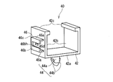
- FIG. 3 is a perspective view showing the first bent state holding vehicle fixing part 40
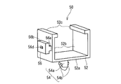
- FIG. 4 is a perspective view showing the second bent state holding vehicle fixing part 50
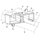
- FIG. 5 is the first bent state holding vehicle. It is a perspective view which shows the united state of the fixing component 40 and the 2nd bending state holding vehicle fixing component 50.
- the first bending state holding vehicle fixing part 40 and the second bending state holding vehicle fixing part 50 are parts attached to the wire harness main body 22 at positions separated in the extending direction.
- the vehicle is attached at a position separated in the extending direction.
- the exterior member 30 is bent in its elastic deformation region, and the first bending state holding vehicle fixing part 40 and the second bending state holding vehicle fixing part 40.
- maintenance is provided.
- first bending state holding vehicle fixing part 40 and the second bending state holding vehicle fixing part 50 may be directly attached to the wire harness body 22.
- a plurality of exterior members are attached to the distant parts, and the first bending state holding vehicle fixing component and the second bending state holding vehicle fixing component are attached to each of the exterior members. Also good.
- Each of the first bending state holding vehicle fixing part 40 and the second bending state holding vehicle fixing part 50 is configured to be attached to the wire harness 21 and attachable to the assembly target location 10 of the vehicle.
- the first bending state holding vehicle fixing component 40 is a component integrally molded with resin or the like, and includes a first harness mounting portion 42, a first vehicle fixing portion 44, and a first combined portion 46. Prepare.
- the first harness attachment portion 42 is configured to be attachable to a part of the extending direction of the exterior member 30.
- the 1st harness attachment part 42 is provided with the base 42a and a pair of side part 42b.
- the base portion 42 a is formed in an elongated plate shape that can be disposed over the entire width direction of the outer surface of the exterior member 30 on the wide side.
- the pair of side portions 42b is formed in a shape that rises from both side portions of the base portion 42a to one main surface side of the base portion 42a.
- the pair of side portions 42 b is formed to have a length dimension that exceeds the outer surface of the exterior member 30 on the narrow side.
- a locking piece 42c that protrudes inward is formed at the tip of the pair of side portions 42b.
- a space in which the exterior member 30 can be disposed is formed between the base portion 42a and the pair of side portions 42b.
- the first harness attachment portion 42 is attached to the exterior member 30 by bringing the stop piece 42c into contact with both sides of the other outer surface on the wide side of the exterior member 30, and the first bending state maintaining vehicle fixing component 40 is secured. It is attached to the exterior member 30 as a whole.
- the first harness attachment portion is formed so as to be attachable to the attachment target in accordance with the shape to be attached.
- the attachment target is a corrugated tube as an exterior member or a wire bundle of the wire harness body 22
- the first harness attachment portion can be held in a substantially circumferential shape. You may form in the character-shaped part.
- the first vehicle fixing portion 44 includes a columnar portion 44a that protrudes outward from the center portion of the outer surface of the base portion 42a, and a pair of retaining protrusions 44b that protrude from the tip of the columnar portion 44a. Is provided.
- the retaining protrusion 44b is provided so as to spread outward from the distal end portion of the columnar portion 44a toward the proximal end portion.
- the retaining protrusion 44b is retained and locked to the peripheral portion of the fixing hole 10h, thereby fixing the first vehicle.
- the portion 44 is fixed at a fixed position with respect to the assembly target location 10.
- the configuration itself of the first vehicle fixing portion 44 is adopted as a structure for mounting on a vehicle as a part called a clamp, a clip or the like.
- the shape that can be fixed to the assembly target location is also adopted for the first vehicle fixing portion in accordance with the shape of the assembly target location.
- One example thereof will be described in a second embodiment to be described later.
- the 1st union part 46 is constituted so that releasable union to the 2nd unification part 56 mentioned below is possible.
- the 1st united part 46 is formed in the 1st side of the 1st harness attaching part 42, ie, the outer surface of one side part 42b.
- the first united portion 46 includes a pair of side portions 46a, a ceiling portion 46b, and a stopper piece portion 46c.
- the pair of side portions 46a is formed in an elongated plate shape provided with a gap in the direction connecting the base end portion and the tip end portion of the side portion 42b.
- a ceiling portion 46b is formed so as to connect the tip portions of the pair of side portions 46a.
- An insertion recess 46bh is formed at the center in the width direction of the ceiling 46b from the one end to the other end in the extending direction of the pair of side portions 46a.
- the stop piece 46c is formed so as to connect the other ends of the pair of side portions 46a.
- a protrusion protrusion that gradually protrudes from the one end side to the other end side in the extending direction of the pair of side portions 46a on the outer surface of the side portion 42b and between the pair of side portions 46a. 46d is formed.
- the second bending state holding vehicle fixing component 50 is a component integrally molded with resin or the like, and includes a second harness mounting portion 52, a second vehicle fixing portion 54, and a second combined portion 56. Prepare.
- the second harness attachment portion 52 is configured to be attachable to a part of the extending direction of the exterior member 30.
- the 2nd harness attachment part 52 is the structure similar to the said 1st harness attachment part 42, and is set as the structure provided with the base 52a and a pair of side part 52b.
- the second harness attachment portion is also formed so as to be attachable to the attachment target in accordance with the shape to be attached.
- the second vehicle fixing portion 54 is configured to be fixable to the assembly target location 10 (see FIG. 1) of the vehicle.
- fixed part 54 is the structure similar to the said 1st vehicle fixing
- the shape that can be fixed to the assembling target location is also adopted for the second vehicle fixing portion in accordance with the shape of the assembling target location.
- One example thereof will be described in a second embodiment to be described later.
- the 2nd uniting part 56 is constituted so that uniting is possible so that removal to the 1st uniting part 46 is possible.
- the second combined portion 56 is formed on one side of the second harness mounting portion 52, that is, on the outer surface of one side portion 52b.
- the second united portion 56 includes a base portion 56a and an insertion piece 56b.
- the base portion 56a is an elongated portion formed along the direction connecting the both ends of the side portion 52b on the outer surface of the side portion 52b (the direction orthogonal to the direction connecting the base end portion and the distal end portion of the side portion 52b). is there.
- the thickness of the base portion 56a is set to be equal to or smaller (slightly smaller) than the width of the insertion recess 46bh, and is formed to be insertable into the insertion recess 46bh.
- the insertion piece 56b is formed in a rectangular piece formed so as to protrude from the distal end portion of the base portion 56a to both sides thereof. Is the thickness dimension of the insertion piece 56b set to be the same or smaller (slightly smaller) than the gap between the side part 42b and the ceiling part 46b, and is the width dimension of the insertion piece 56b the same as the interval between the pair of side parts 46a? It is set small (slightly small).
- a retaining recess 56d into which the retaining projection 46d can be fitted is formed on the outward surface of the insertion piece 56b.
- the positions of the retaining protrusions 46d and the retaining recesses 56d are not limited to the above example, and the concavo-convex relationship may be reversed. In a state where the first combined portion 46 and the second combined portion 56 are combined, a convex portion is formed on one of them, and a concave portion into which the convex portion is fitted is formed on the other.
- the base portion 56a of the first combined portion 46 is inserted into the insertion concave portion 46bh, and the insertion piece 56b is inserted into the space surrounded by the pair of side portions 46a and the ceiling portion 46b.
- the first combined portion 46 and the second combined portion 56 are combined with each other by locking the retaining recess 56d. Further, from this state, when a force is applied to the first united portion 46 in the direction of pulling out the second united portion 56, the first united portion 46 and the second united portion 56 are prevented from coming off due to elastic deformation of at least a part thereof.
- the protrusion 46d and the stopper protrusion 46d are released from being released, the combined state of the first combined part 46 and the second combined part 56 can be canceled, and the second combined part 56 is removed from the first combined part 46. Can do.
- the wire harness module 20 can be fixed to at least one of the first vehicle fixing portion 44 and the second vehicle fixing portion 54, which are a plurality of vehicle fixing components, in a bent form at the time of transportation and at the initial stage of assembly.
- at least one of the first vehicle fixing portion 44 and the second vehicle fixing portion 54 keeps the wire harness 21 bent.
- the first combined portion 46 of the first bending state holding vehicle fixing component 40 and the second combining portion 56 of the second bent state holding vehicle fixing component 50 keep the wire harness 21 bent.
- the first vehicle fixing portion 44 and the second vehicle fixing portion 54 are kept in a state that can be fixed to the assembly target location 10 of the vehicle in a form that is exposed to the outside.
- the first vehicle fixing portion 44 of the first bending state holding vehicle fixing component 40 is kept in a state where the first combining portion 46 and the second combining portion 56 are combined. It is inserted and fixed in one fixing hole 10h of the assembling target location 10, and then the second combined portion 56 is removed from the first combined portion 46, and the wire harness 21 is extended to maintain the second bent state.
- the second vehicle fixing portion 54 of the vehicle fixing component 50 can be fixed by being inserted into one fixing hole 10 h of the assembly target location 10.
- the work of assembling the wire harness 21 to the vehicle can be easily performed.
- the unit of the combined structure of the first bending state holding vehicle fixing part 40 and the second bending state holding vehicle fixing part 50 is a robot hand. And then fixed to the vehicle, and then the robot hand is used to release the first bent state holding vehicle fixing part 40 and the second bent state holding vehicle fixing part 50 to form the second bent state.
- the operation of fixing the holding vehicle fixing component 50 to the vehicle can be easily performed as a series of operations.
- first harness mounting part 42 and the first vehicle fixing part 44 of the first bending state holding vehicle fixing part 40, and the second harness mounting part 52 and the second vehicle fixing part of the second bending state holding vehicle fixing part 50 Since the first united portion 46 and the second united unit 56 are provided separately from 54, the wire harness 21 can be made while minimizing the influence of the function of attaching each component to the wire harness 21 and the function of fixing to the vehicle.
- the first combined part 46 and the second combined part 56 can be provided with emphasis on the function of maintaining the bent shape.
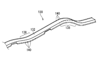
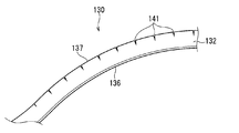
- FIG. 6 is a perspective view showing an exterior member 130 according to a first modification
- FIG. 7 is a cross-sectional view showing the exterior member 130
- FIG. 8 is a view showing a state in which the exterior member 130 is bent.
- the exterior member 130 is a long member formed by extruding a softened resin.
- the extrusion molding is a processing method in which a softened resin is supplied to an extrusion molding die and extruded as a long member having a predetermined cross-sectional shape.
- the long member is manufactured as a member having a predetermined cross-sectional shape corresponding to the shape of the outlet of the extrusion mold. For this reason, by forming the exit shape of the extrusion mold into a predetermined shape to be processed as the exterior member 130, a long member having the same cross-sectional shape along the extending direction can be formed easily and continuously. can do.
- the exterior member 130 includes a main body 132 having a rectangular tube shape.
- the cross-sectional shape of the main body 132 is a rectangular shape in which one set of opposite sides (the opposite sides along the horizontal direction in FIG. 7) is longer than the other set of opposite sides (the opposite sides along the vertical direction in FIG. 7).
- a cross-sectional shape an example of a polygonal cross-sectional shape.
- the main body portion 132 has a rectangular tube shape surrounded by the bottom plate portion 133, the upper plate portion 134, and the pair of side plate portions 135 and 135.
- the direction connecting the bottom plate portion 133 and the upper plate portion 134 will be described as the vertical direction
- the direction connecting the pair of side plate portions 135 and 135 will be described as the width direction. It is not limited to.
- the exterior member 130 is formed with a slit 131 for accommodating the wire harness 21 along its extending direction.
- main body portion 132 of the exterior member 130 is formed with reinforcing protrusions 136 and 137 extending along the extending direction.
- a pair of elongate plate-shaped reinforcing protrusions 136 are formed from both side edge portions of the bottom plate portion 133 toward the outside of the pair of side plate portions 135. Further, a pair of elongated protrusions 137 are formed from the edge of the pair of side plates 135 toward the outer side (upward) of the upper plate 134 from the edge on the upper plate 134 side.
- each of the reinforcing protrusions 136 and 137 is formed in a shape that gradually becomes thinner toward the outside thereof, but this is not essential.
- the exterior member 130 can be made difficult to bend in the width direction and the vertical direction, and the straight line state can be more reliably established. Can be maintained.
- the reinforcing protrusions 136 and 137 appear as protrusions protruding sideways and upward in the cross-sectional shape of the exterior member 130.
- the components including the main body 132 and the reinforcing protrusions 136 and 137 are formed by resin extrusion.
- the exterior member 130 is formed with a separation portion 140 for making it easy to bend partially in the extending direction.
- the separation part 140 is a part where a part of the outer peripheral part of the exterior member 130 is separated on both sides in the extending direction, and is formed by performing additional processing on the extruded long member.
- the additional processing of the separation part 140 can be formed by a press blade, a cutter blade, laser cutting, or the like.
- the cut-off portion 140 only needs to be formed on a part of the outer peripheral portion of the exterior member 130, and therefore may be formed only on the reinforcing protrusion 136 (or the reinforcing protrusion 137), or the main body portion. It may be formed so as to penetrate inside and outside a part of the outer peripheral portion of 132.
- the two first portions 138 in the intermediate portion in the extending direction of the exterior member 130 are gently bent in opposite directions and bent so as to draw a gentle S-shaped curve in plan view (see FIG. 6). .
- a plurality of separation portions 140 are formed at intervals in the portion of the first portion 138 that faces the outer peripheral side in a bent state. For this reason, the portion of the first portion 138 can be bent easily by opening the reinforcing protrusions 136 or 137 on one side at the respective separation portions 140.
- the separating portion is formed in a shape that separates linearly, but the separating portion may be formed in a shape that separates the electric wire exterior member with a width in the extending direction. Good.
- this part is a path regulating unit that regulates the path of the wire harness 21.
- the 1st part 138 in which the separation part 140 was formed among the exterior members 30 is an easily bendable part which is easier to bend than the path regulating part.
- the exterior member 130 is attached by attaching the first bent state holding vehicle fixing part 40 and the second bent state holding vehicle fixing part 50, and combining them.
- the member 30 can be held in a certain conveying form, and the same effect as described in the above embodiment can be obtained.
- the first portion 138 may be provided in a portion that bends in a state where the first bending state holding vehicle fixing component 40 and the second bending state holding vehicle fixing component 50 are combined.
- the first portion 138 may be provided in a portion that is bent and disposed in a state in which the wire harness module including the exterior member 130 is assembled to the vehicle.
- portions other than these portions may be set as route restriction portions that are not provided with the separation portion.
- the wire harness module including the exterior member 130 can be more reliably maintained in a certain state in the conveyance form and the arrangement form in the vehicle.
- a thick annular part and a narrow annular part include those described in this modification.
- a cylindrical member or the like in which a corrugated tube-shaped portion that is alternately continuous in the extending direction and a cylindrical portion in which the same-shaped portion (the same-diameter portion) is continuous can be used.
- At least one of the plurality of vehicle fixing parts may be provided with an end holding portion that holds the end of the wire harness main body 22.
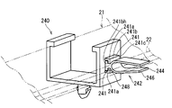
- the first bent state holding vehicle fixing component 240 corresponding to the first bent state holding vehicle fixing component 40 is provided with an end holding portion 242 that holds the end of the wire harness 21. It is a figure which shows an example.
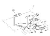
- the end holding portion 242 is provided so as to be separable from the first harness attaching portion 42 or the first vehicle fixing portion 44, and FIG. 9 shows that the end holding portion 242 is separated from the first harness attaching portion 42.
- FIG. 10 shows a state in which the end holding portion 242 is separated from the first harness mounting portion 42.
- the end holding portion 242 is provided on the outer surface of the side portion 42b on the opposite side of the pair of side portions 42b of the first bending state holding vehicle fixing component 240 from the one where the first combined portion 46 is provided.
- the end holding part uniting part 241 and the end holding part 244 are provided.
- the end holding part uniting part 241 includes a pair of side parts 241a, a ceiling part 241b, and a stopper piece part 241c.
- the pair of side portions 241a is formed in an elongated plate shape that is provided with an interval in a direction connecting the base end portion and the tip end portion of the side portion 42b.
- a ceiling portion 241b is formed so as to connect the tip portions of the pair of side portions 241a.
- An insertion recess 241bh extending from one end side in the extending direction of the pair of side portions 241a to the other end side is formed in the center portion in the width direction of the ceiling portion 241b.
- the stop piece 241c is formed so as to connect the other ends of the pair of side portions 241a.
- the end holding component 244 is a component that is integrally molded with resin or the like, and includes a harness holding portion 246 and a combined portion 248.
- the harness holding part 246 is formed in a U-shape, and the width of the base end part is set smaller than the width of the opening on the front end side. Then, when any one end of the wire harness 21 is disposed in the harness holding part 246, the end of the wire harness 21 is held in a state of being held by the harness holding part 246. At this time, since the opening on the front end side of the harness holding portion 246 is formed to be narrow, dropping of the end portion of the wire harness 21 is suppressed. When the end of the wire harness 21 is moved toward the opening of the harness holding portion 246 and the end opening of the harness holding portion 246 is elastically opened, the end of the wire harness 21 is removed from the harness holding portion 246. be able to.
- the union part 248 is provided in the outward part of the base end part of the harness clamping part 246.
- the united portion 248 includes a base portion 248a and an insertion piece 248b.
- the base 248a is formed in an elongated shape.
- the thickness dimension of the base 248a is set to be the same as or smaller (slightly smaller) than the width of the insertion recess 241bh, and is formed to be insertable into the insertion recess 241bh.
- the insertion piece 248b is formed in a square piece formed so as to protrude from the tip end portion of the base portion 248a to both sides thereof.
- the thickness dimension of the insertion piece 248b is set to be the same or smaller (slightly smaller) than the gap between the side part 42b and the ceiling part 241b, and is the width dimension of the insertion piece 248b the same as the distance between the pair of side parts 241a? It is set small (slightly small).
- the base portion 248a of the merged portion 248 is inserted into the insertion recess 241bh, and the insertion piece 248b is inserted into the space surrounded by the pair of side portions 241a and the ceiling portion 241b, thereby combining the end holding portion merged portion.
- 241 and the merged portion 248 are merged. Further, from this state, when a force is applied in a direction in which the united portion 248 is pulled out from the end holding unit united portion 241, the united state can be released, and the united portion 248 can be connected to the end holding unit united portion 241. Can be removed.
- maintenance part united part 241 and the united part 248 may be formed with a convex part and a concave part that are locked in the combined state.
- the end portion of the wire harness 21 can be held by the first bending state holding vehicle fixing component 240, which is at least one of the plurality of vehicle fixing components, so that the wire harness module can be made more compact. It can be in the form.
- maintenance component 244 is separable from the 1st harness attachment part 42 and the 1st vehicle fixing
- the end holding component 244 that has been removed is lost, the end holding component 244 does not get in the way, and interference with other parts of the vehicle can be suppressed.
- the end holding component 244 may be collected and reused or discarded.
- the example in which the end holding portion 242 is provided in the first bending state holding vehicle fixing component 240 has been described.
- the second bending state holding vehicle fixing component 50 has an end.
- a part holding part may be provided.
- the end holding component 244 has been described as an example that can be combined with the end holding unit combining unit 241, but the part holding the end of the wire harness is a thin part, a thin part, etc. It may be integrally formed in a state where it is connected to the harness mounting portion or the vehicle fixing portion via the weakened portion, and after the wire harness is assembled to the vehicle, it may be broken and separated at the weakened portion.
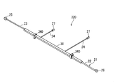
- FIG. 11 is a schematic perspective view showing a form in which the wire harness module 320 is extended
- FIG. 12 is a schematic perspective view showing the wire harness module 320.
- the wire harness module 320 in an initial state in which the work is arranged in the vehicle from the folded state is shown by a solid line
- the wire harness module 320 extended from this state is shown by a two-dot chain line. ing.
- the same components as those described in the first embodiment may be denoted by the same reference numerals and description thereof may be omitted.
- the wire harness module 320 includes the wire harness 21 and a plurality of vehicle fixing parts 340 as a plurality of vehicle fixing parts.
- the wire harness 21 has the same configuration as that described in the first embodiment, and has a configuration in which an exterior member 30 is sheathed on the wire harness body 22.
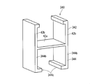
- FIG. 13 is a schematic perspective view showing the vehicle fixing component 340.
- the assembling target part 310 is an elongated frame-shaped part, more specifically, a rectangular cylindrical part having the same width and height as the exterior member 30.
- the vehicle fixing part 340 is a part integrally molded with resin or the like, and includes a harness attachment part 342 and a vehicle fixing part 344.
- the harness attachment part 342 is a component similar to the first harness attachment part 42.
- the vehicle fixing portion 344 is configured to be attachable to the assembly target location 310 of the vehicle.
- the vehicle fixing portion 344 includes a base portion and a pair of side portions 344b, similarly to the first harness attachment portion 42.
- the base of the vehicle fixing part 344 is shared with the base 42a of the harness mounting part 342.
- the pair of side portions 344b is formed in a shape that rises from both side portions of the base portion 42a to the other main surface side of the base portion 42a (that is, opposite to the pair of side portions 42b of the harness attachment portion 342).
- the pair of side portions 344b is formed to have a length dimension that exceeds the outer surface of the exterior member 30 and the assembly target location 310 on the narrow side.
- a locking piece 344c that protrudes inward is formed at the tip of the pair of side portions 344b.
- a space in which the exterior member 30 or the assembly target location 310 can be disposed is formed between the base portion 42a and the pair of side portions 344b.
- the inward surface of the base portion 42a is brought into contact with one outer surface on the wide side of the exterior member 30 or the assembly target location 310, and the inward surfaces of the pair of side portions 344b are brought into contact with the exterior member 30 or the assembly target location 310.
- the vehicle fixing portion 344 is brought into contact with the pair of outer surfaces on the narrow side, and the locking piece 42c is brought into contact with both sides of the outer member 30 or the other outer surface on the wide side of the assembly target location 310, so And selectively attached to the assembly target location 310.
- a plurality (two in this case) of vehicle fixing components 340 are provided at positions separated from each other in the extending direction with respect to the wire harness 21 (here, the exterior member 30), as in the first embodiment.
- one vehicle fixing component 340 among a plurality (two in this case) of vehicle fixing components 340 is used as a dual-purpose vehicle fixing component.
- the vehicle fixing portion 344 of the one combined vehicle fixing component 340 serves as a harness holding and combined vehicle fixing portion as another portion of the wire harness 21 (here, the other portion of the exterior member 30 and the other vehicle fixing component).
- the position of the wire harness 21 is kept bent (see FIG. 12).
- fixed part 344 of the other vehicle fixing component 340 is exposed outside, and is maintained in the state which can be fixed to a vehicle.
- fixed part) 340 The holding of the wire harness 21 by 344 is released, and the vehicle fixing part (harness holding / vehicle fixing part) 344 of one vehicle fixing part (also used as a vehicle fixing part) 340 is fixed to the assembly target location 310.
- the assembly target location 310 to which the vehicle fixing part 344 of the other vehicle fixing part 340 is fixed, and the vehicle fixing part (harness holding and vehicle fixing part) 344 of one vehicle fixing part (also used as a vehicle fixing part) 340 are illustrated.
- the vehicle harness is fixed to the other vehicle fixing part 340 (harness holding and vehicle fixing part) 344 while the wire harness 21 is kept bent.
- the vehicle fixing part 344 of the part 340 is fixed to the assembly target location 310, and then the vehicle fixing part (harness holding / vehicle fixing part) 344 of one vehicle fixing part (combined vehicle fixing part) 340 is connected from the wire harness 21.
- the wire harness 21 can be removed and the vehicle fixing part (harness holding / vehicle fixing part) 344 of one of the vehicle fixing parts (combined vehicle fixing parts) 340 can be fixed to the assembly target part 310.
- vehicle fixing portion (harness holding and vehicle fixing portion) 344 can be shared with a configuration for holding the wire harness 21 in a bent state and a configuration for fixing the wire harness 21 to the vehicle, and the configuration can be simplified. .
- the said 1st united part 46 or the 2nd united part 56 may be provided in the vehicle fixing
- the end holding portion 242 may be provided in the vehicle fixing component 340 described in the second embodiment.
Abstract
The purpose is to provide a feature suitable for, after fixing to a vehicle a part of a wire harness kept in a bent state, extending said wire harness and assembling the same onto the vehicle. A wire harness module is provided with: a wire harness that includes a plurality of electric wires; and a plurality of vehicle fixing parts attached to the wire harness and also configured to be attachable to the vehicle. In a state in which at least one of the plurality of vehicle fixing parts kept in a state for which fixing to the vehicle is possible, at least one of the plurality of vehicle fixing parts is kept in a mode in which the wire harness bent.
Description
この発明は、車両に組込まれるワイヤーハーネスモジュールに関する。
This invention relates to a wire harness module incorporated in a vehicle.
特許文献1は、複数の電線が束ねられたワイヤーハーネスと、前記ワイヤーハーネスに外装された曲げ可能な外装部材と、前記外装部材又は前記ワイヤーハーネスに取付けられると共に車両に取付可能に構成された少なくとも1つの車両固定部品と、を備え、前記少なくとも1つの車両固定部品が、前記ワイヤーハーネスを曲げた状態に保持する曲げ状態保持用車両固定部品を少なくとも1つ含む、ワイヤーハーネスモジュールを開示している。特に、第1曲げ状態保持用車両固定部品と前記第2曲げ状態保持用車両固定部品とは、それぞれ車両に固定される車両固定部を含み、前記第1曲げ状態保持用車両固定部品と前記第2曲げ状態保持用車両固定部品とは、それぞれの車両固定部同士が係止し合うことで、合体可能に構成されている構成を開示している。
Patent Document 1 discloses at least a wire harness in which a plurality of electric wires are bundled, a bendable exterior member sheathed on the wire harness, and attached to the exterior member or the wire harness and attachable to a vehicle. A wire harness module comprising: at least one vehicle-fixing component for holding a bent state, wherein the at least one vehicle-fixing component holds the wire harness in a bent state. . In particular, the first bending state maintaining vehicle fixing component and the second bending state maintaining vehicle fixing component each include a vehicle fixing portion fixed to the vehicle, and the first bending state maintaining vehicle fixing component and the first bending state maintaining vehicle fixing component The two-bending state holding vehicle fixing component discloses a configuration in which the vehicle fixing portions are engaged with each other so that they can be combined.
しかしながら、第1曲げ状態保持用車両固定部品の車両固定部と第2曲げ状態保持用車両固定部品とが合体する構成であっても、それぞれの車両固定部同士が係止し合うことで合体可能な構成であれば、車両固定部同士の係止を解除した後、各車両固定部を車両に固定する必要がある。このため、ワイヤーハーネスを車両に固定する作業が繁雑となる。
However, even if the vehicle fixing part of the first bending state holding vehicle fixing part and the second bending state holding vehicle fixing part are combined, the vehicle fixing parts can be combined to engage with each other. If it is a simple structure, it is necessary to fix each vehicle fixing | fixed part to a vehicle, after canceling | releasing locking of vehicle fixing | fixed parts. For this reason, the operation | work which fixes a wire harness to a vehicle becomes complicated.
そこで、本発明は、曲げられた状態に保たれたワイヤーハーネスの一部を車両に固定した後、当該ワイヤーハーネスを延ばして車両に組付するのに適した技術を提供することを目的とする。
Then, this invention aims at providing the technique suitable for extending the said wire harness and assembling | attaching to a vehicle, after fixing a part of the wire harness kept in the bent state to a vehicle. .
上記課題を解決するため、第1の態様に係るワイヤーハーネスモジュールは、複数の電線を含むワイヤーハーネスと、前記ワイヤーハーネスに取付けられると共に車両に取付可能に構成された複数の車両固定部品と、を備え、前記複数の車両固定部品のうちの少なくとも1つを車両に固定可能な状態に保った状態で、前記複数の車両固定部品の少なくとも1つが前記ワイヤーハーネスを曲げた形態に保っているものである。
In order to solve the above-described problem, a wire harness module according to a first aspect includes a wire harness including a plurality of electric wires, and a plurality of vehicle fixing parts that are attached to the wire harness and configured to be attachable to a vehicle. And at least one of the plurality of vehicle fixing parts is maintained in a state that can be fixed to the vehicle, and at least one of the plurality of vehicle fixing parts is maintained in a bent form of the wire harness. is there.
第2の態様は、第1の態様に係るワイヤーハーネスモジュールであって、前記複数の車両固定部品は、前記ワイヤーハーネスに対して離れた位置に取付けられた第1曲げ状態保持用車両固定部品と第2曲げ状態保持用車両固定部品とを備え、前記第1曲げ状態保持用車両固定部品は、前記ワイヤーハーネスに取付けられた第1ハーネス取付部と、車両に固定可能な第1車両固定部と、第1合体部とを備え、前記第2曲げ状態保持用車両固定部品は、前記ワイヤーハーネスに取付けられた第2ハーネス取付部と、車両に固定可能な第2車両固定部と、前記第1合体部に対して取外し可能に合体する第2合体部とを備えるものである。
A 2nd aspect is a wire harness module which concerns on a 1st aspect, Comprising: These vehicle fixing components are the vehicle fixing components for 1st bending state holding | maintenance attached to the position away with respect to the said wire harness. A second bending state holding vehicle fixing part, wherein the first bending state holding vehicle fixing part includes a first harness attachment part attached to the wire harness, and a first vehicle fixing part fixable to the vehicle. The second bent state holding vehicle fixing component includes a second harness mounting portion attached to the wire harness, a second vehicle fixing portion fixable to the vehicle, and the first And a second coalesced portion that can be detached from the coalesced portion.
第3の態様は、第1又は第2の態様に係るワイヤーハーネスモジュールであって、前記複数の車両固定部品は、前記ワイヤーハーネスを曲げた形態に保つ少なくとも1つの車両固定部品として、前記ワイヤーハーネスに取付けられたハーネス取付部と、車両に固定可能でかつ前記ワイヤーハーネスを曲げた形態に保つハーネス保持兼用車両固定部とを備える兼用車両固定部品を含むものである。
A 3rd aspect is a wire harness module which concerns on a 1st or 2nd aspect, Comprising: The said several vehicle fixing component is the said wire harness as at least 1 vehicle fixing component maintained in the form which bent the said wire harness. And a harness mounting portion that is fixed to the vehicle and a harness holding and vehicle fixing portion that can be fixed to the vehicle and that keeps the wire harness bent.
第4の態様は、第1から第3のいずれか1つの態様に係るワイヤーハーネスモジュールであって、前記複数の車両固定部品の少なくとも1つに、前記ワイヤーハーネスの端部を保持する端部保持部が設けられているものである。
A 4th aspect is a wire harness module which concerns on any one 1st-3rd aspect, Comprising: The edge part holding | maintenance which hold | maintains the edge part of the said wire harness to at least 1 of these vehicle fixing components The part is provided.
第5の態様は、第4の態様に係るワイヤーハーネスモジュールであって、前記端部保持部は、前記複数の車両固定部品の少なくとも1つのうち前記ワイヤーハーネスに取付けられる部分又は車両に取付可能に構成された部分に対して分離可能に設けられた端部保持部品を含むものである。
A 5th aspect is a wire harness module which concerns on a 4th aspect, Comprising: The said edge part holding | maintenance part can be attached to the part attached to the said wire harness among at least one of these vehicle fixing components, or a vehicle. It includes an end holding component that is separable from the constructed portion.
第1の態様によると、複数の車両固定部品のうち車両に固定可能な状態に保たれたものを、車両に固定した後、ワイヤーハーネスを延ばして車両に組付するができる。
According to the first aspect, after fixing one of the plurality of vehicle fixing parts that is fixed to the vehicle to the vehicle, the wire harness can be extended and assembled to the vehicle.
第2の態様によると、第1曲げ状態保持用車両固定部品の第1ハーネス取付部及び第1車両固定部、第2曲げ状態保持用車両固定部品の第2ハーネス取付部及び第2車両固定部とは別に、第1合体部及び第2合体部を設けているため、ワイヤーハーネスへの取付機能及び車両への固定機能に対する影響をなるべく少なくできる。
According to the second aspect, the first harness mounting portion and the first vehicle fixing portion of the first bending state holding vehicle fixing component, the second harness mounting portion and the second vehicle fixing portion of the second bending state holding vehicle fixing component. Apart from this, since the first combined part and the second combined part are provided, the influence on the mounting function to the wire harness and the fixing function to the vehicle can be reduced as much as possible.
第3の態様によると、複数の車両固定部品のうちの少なくとも1つを車両に固定した後、兼用車両固定部品のハーネス兼用車両固定部によるワイヤーハーネスの保持を解除し、当該ワイヤーハーネスを延ばしてハーネス保持兼用車両固定部を車両に固定することができる。また、ハーネス保持兼用車両固定部を、ハーネスを曲げた状態に保持する構成及び車両に固定するための構成と兼用することができ、構成の簡易化が可能となる。
According to the third aspect, after fixing at least one of the plurality of vehicle fixing parts to the vehicle, the holding of the wire harness by the harness / vehicle fixing part of the combined vehicle fixing part is released, and the wire harness is extended. The harness holding and vehicle fixing portion can be fixed to the vehicle. In addition, the harness holding and vehicle fixing portion can also be used as a configuration for holding the harness in a bent state and a configuration for fixing the harness to the vehicle, thereby simplifying the configuration.
第4の態様によると、複数の車両固定部品の少なくとも1つに、ワイヤーハーネスの端部を保持することで、ワイヤーハーネスモジュールをよりコンパクトな形態とすることができる。
According to the 4th aspect, a wire harness module can be made into a more compact form by hold | maintaining the edge part of a wire harness to at least 1 of several vehicle fixing components.
第5の態様によると、ワイヤーハーネスモジュールを車両に組付けた後は、端部保持部を分離させることができるため、端部保持部が邪魔にならない。
According to the fifth aspect, after the wire harness module is assembled to the vehicle, the end holding portion can be separated, so that the end holding portion does not get in the way.
{第1実施形態}
以下、第1実施形態に係るワイヤーハーネスモジュールについて説明する。図1はワイヤーハーネスモジュール20を車両に配設した形態を示す概略斜視図であり、図2はワイヤーハーネスモジュール20を示す概略斜視図である。図2に示すワイヤーハーネスモジュール20は、搬送形態に折畳まれた状態から車両に配設作業する初期状態を示している。 {First embodiment}
Hereinafter, the wire harness module according to the first embodiment will be described. FIG. 1 is a schematic perspective view showing a form in which thewire harness module 20 is disposed in a vehicle, and FIG. 2 is a schematic perspective view showing the wire harness module 20. The wire harness module 20 shown in FIG. 2 has shown the initial state which arrange | positions to a vehicle from the state folded by the conveyance form.
以下、第1実施形態に係るワイヤーハーネスモジュールについて説明する。図1はワイヤーハーネスモジュール20を車両に配設した形態を示す概略斜視図であり、図2はワイヤーハーネスモジュール20を示す概略斜視図である。図2に示すワイヤーハーネスモジュール20は、搬送形態に折畳まれた状態から車両に配設作業する初期状態を示している。 {First embodiment}
Hereinafter, the wire harness module according to the first embodiment will be described. FIG. 1 is a schematic perspective view showing a form in which the
ワイヤーハーネスモジュール20は、ワイヤーハーネス21と、複数の車両固定部品としての第1曲げ状態保持用車両固定部品40及び第2曲げ状態保持用車両固定部品50とを備える。
The wire harness module 20 includes a wire harness 21, a first bending state holding vehicle fixing component 40 and a second bending state holding vehicle fixing component 50 as a plurality of vehicle fixing components.
ワイヤーハーネス21は、複数の電線を含む。ここでは、ワイヤーハーネス21は、複数の電線が束ねられることにより形成されたワイヤーハーネス本体22を含む。なお、各図では、複数の電線が束ねられた外形を示している。ワイヤーハーネス本体22は、その延在方向途中で分岐していてもよく、そのような分岐が無く1つに束ねられていてもよい。図1及び図2に示す例では、ワイヤーハーネス本体22は、その延在方向途中の2箇所で分岐している。ここでは、ワイヤーハーネス本体22は、幹線部分23と、当該幹線部分23の途中で分岐する分岐部分24とを備えている。ワイヤーハーネス本体22には、光ケーブル等が含まれていてもよい。
The wire harness 21 includes a plurality of electric wires. Here, the wire harness 21 includes a wire harness body 22 formed by bundling a plurality of electric wires. In each drawing, an outer shape in which a plurality of electric wires are bundled is shown. The wire harness body 22 may be branched in the middle of its extending direction, or may be bundled together without such a branch. In the example shown in FIG.1 and FIG.2, the wire harness main body 22 is branched in two places in the middle of the extension direction. Here, the wire harness body 22 includes a trunk portion 23 and a branch portion 24 that branches in the middle of the trunk portion 23. The wire harness body 22 may include an optical cable or the like.
ワイヤーハーネス本体22の各端部、すなわち、幹線部分23の両端部には、コネクタ25、26が取付けられ、分岐部分24の端部には、コネクタ27が取付けられている。
Connectors 25 and 26 are attached to each end of the wire harness main body 22, that is, both ends of the trunk portion 23, and a connector 27 is attached to the end of the branch portion 24.
コネクタ25、26、27は、それぞれ1つのハウジング部を有するコネクタであり、電線の端部の端子が当該ハウジング部のキャビティ内に挿入保持されることによって、幹線部分23の端部及び分岐部分24の端部にコネクタ25、26、27が取付けられている。
Each of the connectors 25, 26, and 27 is a connector having one housing portion, and the end portion of the trunk portion 23 and the branch portion 24 are obtained by inserting and holding the terminal at the end portion of the electric wire in the cavity of the housing portion. Connectors 25, 26, and 27 are attached to the ends of the connectors.
そして、本ワイヤーハーネス21が車両に組付けられた状態で、各コネクタ25、26、27が相手側のコネクタに接続される。これにより、当該相手側のコネクタに接続されている各種電気部品同士が電気的に接続される。すなわち、本ワイヤーハーネス本体22は、車両における各種電気部品同士を電気的に接続する配線材として用いられる。
Then, in a state where the wire harness 21 is assembled to the vehicle, the connectors 25, 26, 27 are connected to the mating connectors. Thereby, the various electrical components connected to the counterpart connector are electrically connected. That is, this wire harness main body 22 is used as a wiring material that electrically connects various electric components in the vehicle.
なお、本ワイヤーハーネス21が組付けられる車両は、4輪自動車であってもよいし、2輪自動車であってもよい。組付対象箇所は、金属板等のパネル状である場合、角筒状又は円筒状の細長い部材である場合等が想定される。ここでは、組付対象箇所10は、金属板等のパネル状であり、当該組付対象箇所10に複数の固定孔10hが形成されている例で説明する(図2に1つのみ図示)。
The vehicle to which the wire harness 21 is assembled may be a four-wheeled vehicle or a two-wheeled vehicle. The assembly target location may be a panel shape such as a metal plate, or may be a rectangular or cylindrical elongated member. Here, the assembly target location 10 is in the form of a panel such as a metal plate, and an example in which a plurality of fixing holes 10h are formed in the assembly target location 10 will be described (only one is shown in FIG. 2).
上記ワイヤーハーネス本体22には、曲げ可能な外装部材30が外装されている。
The bendable exterior member 30 is armored on the wire harness body 22.
ここでは、外装部材30は、樹脂を押出成形することによって形成された筒状部材である。外装部材30が軟質な樹脂又は曲げ可能な程度の厚みの筒状に形成されていれば、外装部材30を曲げ可能に構成することができる。例えば、外装部材30は、ポリ塩化ビニル(PVC)、ポリプロピレン(PP)、ポリエチレン(PE)、ポリアミド(PA)、ポリエチレンテレフタレート(PET)等をベース樹脂とする材料によって形成するとよい。
Here, the exterior member 30 is a cylindrical member formed by extruding resin. If the exterior member 30 is formed of a soft resin or a cylindrical shape having a bendable thickness, the exterior member 30 can be configured to be bendable. For example, the exterior member 30 may be formed of a material having a base resin of polyvinyl chloride (PVC), polypropylene (PP), polyethylene (PE), polyamide (PA), polyethylene terephthalate (PET), or the like.
ここでは、外装部材30の延在方向全体が、直線状態から所定方向に最もよく曲るように曲げ方向を規制された構成とされている。具体的には、外装部材30の延在方向に対して直交する面において、外装部材30の断面形状が細長い環状形状、ここでは、一方に長い長方形環状をなすように形成されている。換言すれば、外装部材30は、長方形角筒状に形成されている。かかる外装部材30は、その直線状態から、その断面形状が短い方向(図1の矢符A方向参照)においては比較的容易に曲ることができる一方、その断面形状が長い方向(図1の矢符B方向参照)においては前者の方向よりも曲り難い。このため、外装部材30の延在方向の全体が、直線状態から所定方向(図1の矢符A方向参照)に最もよく曲るように曲げ方向を規制する曲げ方向規制部として構成されていることになる。
Here, the entire extending direction of the exterior member 30 is configured such that the bending direction is regulated so as to bend best in a predetermined direction from the linear state. Specifically, on the surface orthogonal to the extending direction of the exterior member 30, the cross-sectional shape of the exterior member 30 is formed to be an elongated annular shape, in this case, a long rectangular annular shape on one side. In other words, the exterior member 30 is formed in a rectangular rectangular tube shape. From the straight state, the exterior member 30 can be bent relatively easily in the direction in which the cross-sectional shape is short (see the direction of arrow A in FIG. 1), while the direction in which the cross-sectional shape is long (in FIG. 1). In the direction of arrow B), it is harder to bend than the former direction. For this reason, it is comprised as a bending direction control part which controls a bending direction so that the whole extension direction of the exterior member 30 may bend best from a linear state to a predetermined direction (refer arrow A direction of FIG. 1). It will be.
なお、上記ワイヤーハーネス21は、外装部材30の一端側の開口から当該外装部材30内に通していくことによって、または、外装部材30にその延在方向に沿ったスリットを形成し、そのスリットを通じて外装部材30内に配設される。また、外装部材30の延在方向の途中には開口が形成されており、分岐部分24は当該開口を通って外部に引出されている。
In addition, the said wire harness 21 forms the slit along the extension direction in the exterior member 30 by passing in the said exterior member 30 from the opening of the one end side of the exterior member 30, and through the slit It is disposed in the exterior member 30. An opening is formed in the middle of the extending direction of the exterior member 30, and the branch portion 24 is drawn out through the opening.
なお、外装部材は、その他、楕円筒形状等であっても、所定方向に最もよく曲るように曲げ方向を規制することができる。
In addition, even if the exterior member has an elliptical cylindrical shape or the like, the bending direction can be regulated so as to bend best in a predetermined direction.
もっとも、外装部材が所定方向に最もよく曲るように曲げ方向を規制していることは必須ではなく、外装部材は円筒形状、正方形筒形状等に形成されていてもよい。また、外装部材としてコルゲートチューブが用いられてもよい。
However, it is not essential that the bending direction be regulated so that the exterior member bends best in a predetermined direction, and the exterior member may be formed in a cylindrical shape, a square cylindrical shape, or the like. Further, a corrugated tube may be used as the exterior member.
図3は第1曲げ状態保持用車両固定部品40を示す斜視図であり、図4は第2曲げ状態保持用車両固定部品50を示す斜視図であり、図5は第1曲げ状態保持用車両固定部品40と第2曲げ状態保持用車両固定部品50との合体状態を示す斜視図である。
FIG. 3 is a perspective view showing the first bent state holding vehicle fixing part 40, FIG. 4 is a perspective view showing the second bent state holding vehicle fixing part 50, and FIG. 5 is the first bent state holding vehicle. It is a perspective view which shows the united state of the fixing component 40 and the 2nd bending state holding vehicle fixing component 50.
第1曲げ状態保持用車両固定部品40及び第2曲げ状態保持用車両固定部品50は、ワイヤーハーネス本体22に対してその延在方向において離れた位置に取付けられた部品である。ここでは、第1曲げ状態保持用車両固定部品40及び第2曲げ状態保持用車両固定部品50に外装された単一の外装部材30に対してその延在方向において離れた位置に取付けられている。第1曲げ状態保持用車両固定部品40と第2曲げ状態保持用車両固定部品50との間には、外装部材30をその弾性変形域で曲げて第1曲げ状態保持用車両固定部品40と第2曲げ状態保持用車両固定部品50とを合体させることができる寸法以上の間隔が設けられている。
The first bending state holding vehicle fixing part 40 and the second bending state holding vehicle fixing part 50 are parts attached to the wire harness main body 22 at positions separated in the extending direction. Here, with respect to the single exterior member 30 sheathed on the first bent state holding vehicle fixing part 40 and the second bent state holding vehicle fixing part 50, the vehicle is attached at a position separated in the extending direction. . Between the first bending state holding vehicle fixing part 40 and the second bending state holding vehicle fixing part 50, the exterior member 30 is bent in its elastic deformation region, and the first bending state holding vehicle fixing part 40 and the second bending state holding vehicle fixing part 40. The space | interval more than the dimension which can unite with the vehicle fixing component 50 for 2 bending state holding | maintenance is provided.
もっとも、第1曲げ状態保持用車両固定部品40及び第2曲げ状態保持用車両固定部品50は、ワイヤーハーネス本体22に直接取付けられていてもよい。また、ワイヤーハーネス本体に対して、離れた部位に複数の外装部材が取付けられ、それぞれの外装部材に第1曲げ状態保持用車両固定部品及び第2曲げ状態保持用車両固定部品が取付けられていてもよい。
However, the first bending state holding vehicle fixing part 40 and the second bending state holding vehicle fixing part 50 may be directly attached to the wire harness body 22. Moreover, with respect to the wire harness body, a plurality of exterior members are attached to the distant parts, and the first bending state holding vehicle fixing component and the second bending state holding vehicle fixing component are attached to each of the exterior members. Also good.
第1曲げ状態保持用車両固定部品40及び第2曲げ状態保持用車両固定部品50のそれぞれは、ワイヤーハーネス21に取付けられると共に車両の組付対象箇所10に取付可能に構成されている。
Each of the first bending state holding vehicle fixing part 40 and the second bending state holding vehicle fixing part 50 is configured to be attached to the wire harness 21 and attachable to the assembly target location 10 of the vehicle.
第1曲げ状態保持用車両固定部品40は、樹脂等によって一体的に金型成形された部品であり、第1ハーネス取付部42と、第1車両固定部44と、第1合体部46とを備える。
The first bending state holding vehicle fixing component 40 is a component integrally molded with resin or the like, and includes a first harness mounting portion 42, a first vehicle fixing portion 44, and a first combined portion 46. Prepare.
第1ハーネス取付部42は、外装部材30の延在方向の一部に取付可能に構成されている。ここでは、第1ハーネス取付部42は、基部42aと、一対の側部42bとを備える。
The first harness attachment portion 42 is configured to be attachable to a part of the extending direction of the exterior member 30. Here, the 1st harness attachment part 42 is provided with the base 42a and a pair of side part 42b.
基部42aは、外装部材30の幅広側の外面に対してその幅方向全体に亘って配設可能な細長板状に形成されている。一対の側部42bは、基部42aの両側部から基部42aの一方主面側に立上がる形状に形成されている。一対の側部42bは、外装部材30の幅狭側の外面を越える程度の長さ寸法に形成されている。また、一対の側部42bの先端部には、その内向きに突出する係止片42cが形成されている。基部42aと一対の側部42bとの間に、外装部材30を配設可能な空間が形成されている。
The base portion 42 a is formed in an elongated plate shape that can be disposed over the entire width direction of the outer surface of the exterior member 30 on the wide side. The pair of side portions 42b is formed in a shape that rises from both side portions of the base portion 42a to one main surface side of the base portion 42a. The pair of side portions 42 b is formed to have a length dimension that exceeds the outer surface of the exterior member 30 on the narrow side. A locking piece 42c that protrudes inward is formed at the tip of the pair of side portions 42b. A space in which the exterior member 30 can be disposed is formed between the base portion 42a and the pair of side portions 42b.
そして、基部42aの内向き面を外装部材30の幅広側の一方の外面に接触させると共に、一対の側部42bの内向き面を外装部材30の幅狭側の一対の外面に接触させ、係止片42cを外装部材30の幅広側の他方の外面の両側部に当接させることで、第1ハーネス取付部42が外装部材30に対して取付けられ、第1曲げ状態保持用車両固定部品40全体としても外装部材30に取付けられる。
Then, the inward surface of the base portion 42a is brought into contact with one outer surface on the wide side of the exterior member 30, and the inward surfaces of the pair of side portions 42b are brought into contact with a pair of outer surfaces on the narrow side of the exterior member 30. The first harness attachment portion 42 is attached to the exterior member 30 by bringing the stop piece 42c into contact with both sides of the other outer surface on the wide side of the exterior member 30, and the first bending state maintaining vehicle fixing component 40 is secured. It is attached to the exterior member 30 as a whole.
第1ハーネス取付部は、取付対象となる形状に合せて当該取付対象に取付可能に形成されている。例えば、取付対象が、外装部材としてのコルゲートチューブである場合、又は、ワイヤーハーネス本体22の電線束である場合等には、第1ハーネス取付部は、略円周面形状に抱持可能なC字状の部分に形成されていてもよい。
The first harness attachment portion is formed so as to be attachable to the attachment target in accordance with the shape to be attached. For example, when the attachment target is a corrugated tube as an exterior member or a wire bundle of the wire harness body 22, the first harness attachment portion can be held in a substantially circumferential shape. You may form in the character-shaped part.
第1車両固定部44は、車両の組付対象箇所10(図1参照)に固定可能に構成されている。ここでは、第1車両固定部44は、基部42aの外面の中央部から外方に向けて突出する柱状部44aと、柱状部44aの先端部に突設された一対の抜止め突部44bとを備える。抜止め突部44bは、柱状部44aの先端部から基端部に向けて外方に広がるように突設されている。そして、上記組付対象箇所10の固定孔10hに本第1車両固定部44を挿入すると、前記抜止め突部44bが固定孔10hの周縁部に抜止め係止し、もって、第1車両固定部44が組付対象箇所10に対して一定位置に固定される。この第1車両固定部44の構成自体は、クランプ、クリップ等とよばれる部品として、車両への取付用構造として採用されているものである。
1st vehicle fixing | fixed part 44 is comprised so that fixing to the assembly | attachment object location 10 (refer FIG. 1) of a vehicle is possible. Here, the first vehicle fixing portion 44 includes a columnar portion 44a that protrudes outward from the center portion of the outer surface of the base portion 42a, and a pair of retaining protrusions 44b that protrude from the tip of the columnar portion 44a. Is provided. The retaining protrusion 44b is provided so as to spread outward from the distal end portion of the columnar portion 44a toward the proximal end portion. When the first vehicle fixing portion 44 is inserted into the fixing hole 10h of the assembly target location 10, the retaining protrusion 44b is retained and locked to the peripheral portion of the fixing hole 10h, thereby fixing the first vehicle. The portion 44 is fixed at a fixed position with respect to the assembly target location 10. The configuration itself of the first vehicle fixing portion 44 is adopted as a structure for mounting on a vehicle as a part called a clamp, a clip or the like.
第1車両固定部も、組付対象箇所の形状に合せて、当該組付対象箇所に固定可能な形状が採用される。その一例については、後述する第2実施形態において説明する。
The shape that can be fixed to the assembly target location is also adopted for the first vehicle fixing portion in accordance with the shape of the assembly target location. One example thereof will be described in a second embodiment to be described later.
第1合体部46は、後述する第2合体部56に対して取外し可能に合体可能に構成されている。
The 1st union part 46 is constituted so that releasable union to the 2nd unification part 56 mentioned below is possible.
ここでは、第1合体部46は、第1ハーネス取付部42の一側面、すなわち、一方の側部42bの外面に形成されている。第1合体部46は、一対の側部46aと、天井部46bと、止め片部46cとを備える。一対の側部46aは、側部42bの基端部と先端部とを結ぶ方向において間隔をあけて設けられた細長板状に形成されている。一対の側部46aの先端部の間を繋ぐように天井部46bが形成されている。天井部46bの幅方向中央部には、一対の側部46aの延在方向一端側から他端側に向う挿入凹部46bhが形成されている。止め片部46cは、一対の側部46aの他端部同士を繋ぐように形成されている。また、側部42bの外面であって一対の側部46aの間の部分に、一対の側部46aの延在方向一端側から他端側に向けて徐々に突出寸法が大きくなる抜け止凸部46dが形成されている。
Here, the 1st united part 46 is formed in the 1st side of the 1st harness attaching part 42, ie, the outer surface of one side part 42b. The first united portion 46 includes a pair of side portions 46a, a ceiling portion 46b, and a stopper piece portion 46c. The pair of side portions 46a is formed in an elongated plate shape provided with a gap in the direction connecting the base end portion and the tip end portion of the side portion 42b. A ceiling portion 46b is formed so as to connect the tip portions of the pair of side portions 46a. An insertion recess 46bh is formed at the center in the width direction of the ceiling 46b from the one end to the other end in the extending direction of the pair of side portions 46a. The stop piece 46c is formed so as to connect the other ends of the pair of side portions 46a. In addition, a protrusion protrusion that gradually protrudes from the one end side to the other end side in the extending direction of the pair of side portions 46a on the outer surface of the side portion 42b and between the pair of side portions 46a. 46d is formed.
第2曲げ状態保持用車両固定部品50は、樹脂等によって一体的に金型成形された部品であり、第2ハーネス取付部52と、第2車両固定部54と、第2合体部56とを備える。
The second bending state holding vehicle fixing component 50 is a component integrally molded with resin or the like, and includes a second harness mounting portion 52, a second vehicle fixing portion 54, and a second combined portion 56. Prepare.
第2ハーネス取付部52は、外装部材30の延在方向の一部に取付可能に構成されている。ここでは、第2ハーネス取付部52は、上記第1ハーネス取付部42と同様構成であり、基部52aと、一対の側部52bとを備える構成とされている。
The second harness attachment portion 52 is configured to be attachable to a part of the extending direction of the exterior member 30. Here, the 2nd harness attachment part 52 is the structure similar to the said 1st harness attachment part 42, and is set as the structure provided with the base 52a and a pair of side part 52b.
第2ハーネス取付部も、取付対象となる形状に合せて当該取付対象に取付可能に形成されている。
The second harness attachment portion is also formed so as to be attachable to the attachment target in accordance with the shape to be attached.
第2車両固定部54は、車両の組付対象箇所10(図1参照)に固定可能に構成されている。ここでは、第2車両固定部54は、上記第1車両固定部44と同様構成であり、柱状部54aと、柱状部54aの先端部に突設された一対の抜止め突部54bとを備える構成とされている。
The second vehicle fixing portion 54 is configured to be fixable to the assembly target location 10 (see FIG. 1) of the vehicle. Here, the 2nd vehicle fixing | fixed part 54 is the structure similar to the said 1st vehicle fixing | fixed part 44, and is provided with the columnar part 54a and a pair of retaining protrusion 54b protrudingly provided by the front-end | tip part of the columnar part 54a. It is configured.
第2車両固定部も、組付対象箇所の形状に合せて、当該組付対象箇所に固定可能な形状が採用される。その一例については、後述する第2実施形態において説明する。
The shape that can be fixed to the assembling target location is also adopted for the second vehicle fixing portion in accordance with the shape of the assembling target location. One example thereof will be described in a second embodiment to be described later.
第2合体部56は、第1合体部46に対して取外し可能に合体可能に構成されている。
The 2nd uniting part 56 is constituted so that uniting is possible so that removal to the 1st uniting part 46 is possible.
ここでは、第2合体部56は、第2ハーネス取付部52の一側面、すなわち、一方の側部52bの外面に形成されている。第2合体部56は、基部56aと、挿入片56bとを備える。基部56aは、側部52bの外面において当該側部52bの両端を結ぶ方向(側部52bの基端部と先端部とを結ぶ方向に対して直交する方向)に沿って形成された細長い部分である。基部56aの厚み寸法は、上記挿入凹部46bhの幅と同じか小さく(僅かに小さく)設定され、当該挿入凹部46bhに挿入可能に形成されている。挿入片56bは、基部56aの先端部からその両側に突出するように形成された方形状の片に形成されている。挿入片56bの厚み寸法は、側部42bと天井部46bとの間の隙間と同じか小さく(僅かに小さく)設定され、挿入片56bの幅寸法は、一対の側部46aの間隔と同じか小さく(僅かに小さく)設定されている。
Here, the second combined portion 56 is formed on one side of the second harness mounting portion 52, that is, on the outer surface of one side portion 52b. The second united portion 56 includes a base portion 56a and an insertion piece 56b. The base portion 56a is an elongated portion formed along the direction connecting the both ends of the side portion 52b on the outer surface of the side portion 52b (the direction orthogonal to the direction connecting the base end portion and the distal end portion of the side portion 52b). is there. The thickness of the base portion 56a is set to be equal to or smaller (slightly smaller) than the width of the insertion recess 46bh, and is formed to be insertable into the insertion recess 46bh. The insertion piece 56b is formed in a rectangular piece formed so as to protrude from the distal end portion of the base portion 56a to both sides thereof. Is the thickness dimension of the insertion piece 56b set to be the same or smaller (slightly smaller) than the gap between the side part 42b and the ceiling part 46b, and is the width dimension of the insertion piece 56b the same as the interval between the pair of side parts 46a? It is set small (slightly small).
また、挿入片56bの外向き面には、抜け止凸部46dを嵌込可能な抜け止凹部56dが形成されている。なお、抜け止凸部46d及び抜け止凹部56dの位置は、上記例に限られないし、また、凹凸関係も逆であってもよい。第1合体部46と第2合体部56とが合体した状態で、それらの一方に凸部が形成され、他方に当該凸部が嵌り込む凹部が形成されていればよい。
Further, a retaining recess 56d into which the retaining projection 46d can be fitted is formed on the outward surface of the insertion piece 56b. The positions of the retaining protrusions 46d and the retaining recesses 56d are not limited to the above example, and the concavo-convex relationship may be reversed. In a state where the first combined portion 46 and the second combined portion 56 are combined, a convex portion is formed on one of them, and a concave portion into which the convex portion is fitted is formed on the other.
そして、第1合体部46の基部56aを挿入凹部46bh内に挿入すると共に、挿入片56bを一対の側部46aと天井部46bとで囲まれた空間内に挿入し、抜け止凸部46dを抜け止凹部56dに抜け止係止させることで、第1合体部46と第2合体部56とが合体した状態となる。また、この状態から、第1合体部46に対して第2合体部56を抜く方向に力を加えると、第1合体部46及び第2合体部56の少なくとも一部の弾性変形により、抜け止凸部46dと抜け止凸部46dとの抜け止が解除され、第1合体部46と第2合体部56との合体状態を解除でき、第2合体部56を第1合体部46から取外すことができる。
Then, the base portion 56a of the first combined portion 46 is inserted into the insertion concave portion 46bh, and the insertion piece 56b is inserted into the space surrounded by the pair of side portions 46a and the ceiling portion 46b. The first combined portion 46 and the second combined portion 56 are combined with each other by locking the retaining recess 56d. Further, from this state, when a force is applied to the first united portion 46 in the direction of pulling out the second united portion 56, the first united portion 46 and the second united portion 56 are prevented from coming off due to elastic deformation of at least a part thereof. The protrusion 46d and the stopper protrusion 46d are released from being released, the combined state of the first combined part 46 and the second combined part 56 can be canceled, and the second combined part 56 is removed from the first combined part 46. Can do.
このワイヤーハーネスモジュール20では、搬送時及び組付初期等における曲げ形態において、複数の車両固定部品である、第1車両固定部44及び第2車両固定部54の少なくとも1つの車両に固定可能な状態に保った状態で、第1車両固定部44及び第2車両固定部54の少なくとも1つがワイヤーハーネス21を曲げた形態に保っている。ここでは、第1曲げ状態保持用車両固定部品40の第1合体部46と第2曲げ状態保持用車両固定部品50の第2合体部56とがワイヤーハーネス21を曲げた形態に保っているため、第1車両固定部44及び第2車両固定部54は、外部に露出したままの形態で、車両の組付対象箇所10に固定可能な状態に保たれている。
The wire harness module 20 can be fixed to at least one of the first vehicle fixing portion 44 and the second vehicle fixing portion 54, which are a plurality of vehicle fixing components, in a bent form at the time of transportation and at the initial stage of assembly. In this state, at least one of the first vehicle fixing portion 44 and the second vehicle fixing portion 54 keeps the wire harness 21 bent. Here, the first combined portion 46 of the first bending state holding vehicle fixing component 40 and the second combining portion 56 of the second bent state holding vehicle fixing component 50 keep the wire harness 21 bent. The first vehicle fixing portion 44 and the second vehicle fixing portion 54 are kept in a state that can be fixed to the assembly target location 10 of the vehicle in a form that is exposed to the outside.
このため、例えば、図2に示すように、第1合体部46と第2合体部56とを合体させた状態のまま、第1曲げ状態保持用車両固定部品40の第1車両固定部44を組付対象箇所10の1つの固定孔10hに挿入等して固定し、この後、第1合体部46から第2合体部56を取外し、ワイヤーハーネス21を延して、第2曲げ状態保持用車両固定部品50の第2車両固定部54を組付対象箇所10の1つの固定孔10hに挿入等して固定することができる。
For this reason, for example, as shown in FIG. 2, the first vehicle fixing portion 44 of the first bending state holding vehicle fixing component 40 is kept in a state where the first combining portion 46 and the second combining portion 56 are combined. It is inserted and fixed in one fixing hole 10h of the assembling target location 10, and then the second combined portion 56 is removed from the first combined portion 46, and the wire harness 21 is extended to maintain the second bent state. The second vehicle fixing portion 54 of the vehicle fixing component 50 can be fixed by being inserted into one fixing hole 10 h of the assembly target location 10.
このため、ワイヤーハーネス21を車両に組付ける作業を容易に行える。例えば、ロボット装置等によってワイヤーハーネスモジュール20を車両に組付ける作業を想定すると、第1曲げ状態保持用車両固定部品40及び第2曲げ状態保持用車両固定部品50の合体構造物の部分をロボットハンド等で掴んで車両に固定し、この後、続けて、ロボットハンドで第1曲げ状態保持用車両固定部品40及び第2曲げ状態保持用車両固定部品50の合体を解除して、第2曲げ状態保持用車両固定部品50を車両に固定する作業を、一連の作業として容易に行える。
Therefore, the work of assembling the wire harness 21 to the vehicle can be easily performed. For example, assuming the work of assembling the wire harness module 20 to a vehicle by a robot device or the like, the unit of the combined structure of the first bending state holding vehicle fixing part 40 and the second bending state holding vehicle fixing part 50 is a robot hand. And then fixed to the vehicle, and then the robot hand is used to release the first bent state holding vehicle fixing part 40 and the second bent state holding vehicle fixing part 50 to form the second bent state. The operation of fixing the holding vehicle fixing component 50 to the vehicle can be easily performed as a series of operations.
また、第1曲げ状態保持用車両固定部品40の第1ハーネス取付部42及び第1車両固定部44、第2曲げ状態保持用車両固定部品50の第2ハーネス取付部52及び第2車両固定部54とは別に、第1合体部46及び第2合体部56を設けているため、各部品のワイヤーハーネス21への取付機能及び車両への固定機能に対する影響をなるべく少なくしつつ、ワイヤーハーネス21を曲げ形状に保つ機能を重視して第1合体部46及び第2合体部56を設けることができる。
In addition, the first harness mounting part 42 and the first vehicle fixing part 44 of the first bending state holding vehicle fixing part 40, and the second harness mounting part 52 and the second vehicle fixing part of the second bending state holding vehicle fixing part 50. Since the first united portion 46 and the second united unit 56 are provided separately from 54, the wire harness 21 can be made while minimizing the influence of the function of attaching each component to the wire harness 21 and the function of fixing to the vehicle. The first combined part 46 and the second combined part 56 can be provided with emphasis on the function of maintaining the bent shape.
<変形例>
上記第1実施形態を前提として、各種変形例について説明する。 <Modification>
Various modifications will be described on the premise of the first embodiment.
上記第1実施形態を前提として、各種変形例について説明する。 <Modification>
Various modifications will be described on the premise of the first embodiment.
まず、ワイヤーハーネス本体22に外装部材を外装する場合、外装部材として、ワイヤーハーネスの経路規制を行う経路規制部と、この経路規制部よりも曲げ容易な曲げ容易部とを含むものを用いてもよい。
First, when an exterior member is packaged on the wire harness body 22, even if an exterior member is used that includes a path regulation part that regulates the path of the wire harness and a bendable part that is easier to bend than the path regulation part. Good.
図6は第1変形例に係る外装部材130を示す斜視図であり、図7は同外装部材130を示す断面図であり、図8は同外装部材130を曲げた状態を示す図である。
FIG. 6 is a perspective view showing an exterior member 130 according to a first modification, FIG. 7 is a cross-sectional view showing the exterior member 130, and FIG. 8 is a view showing a state in which the exterior member 130 is bent.
外装部材130は、軟化した樹脂を押出成形することによって形成された長尺部材である。ここで、押出成形とは、軟化した樹脂を押出成形用金型に供給して、所定の断面形状を持つ長尺部材として押出す加工方法である。長尺部材は、押出成形用金型の出口の形状に応じた所定断面形状の部材として製造される。このため、押出成形用金型の出口形状を、外装部材130として加工したい所定形状に形成しておくことで、延在方向に沿って同一断面形状を呈する長尺部材を連続的に容易に成形することができる。
The exterior member 130 is a long member formed by extruding a softened resin. Here, the extrusion molding is a processing method in which a softened resin is supplied to an extrusion molding die and extruded as a long member having a predetermined cross-sectional shape. The long member is manufactured as a member having a predetermined cross-sectional shape corresponding to the shape of the outlet of the extrusion mold. For this reason, by forming the exit shape of the extrusion mold into a predetermined shape to be processed as the exterior member 130, a long member having the same cross-sectional shape along the extending direction can be formed easily and continuously. can do.
具体的には、外装部材130は、四角筒形状をなす本体部132を備える。ここでは、本体部132の横断面形状は、一組の対辺(図7では横方向に沿った対辺)が他の組の対辺(図7では縦方向に沿った対辺)よりも長い長方形状の横断面形状(多角形断面形状の一例)を呈する。より具体的には、本体部132は、底板部133と、上板部134と、一対の側板部135、135とで囲まれる角筒形状をなしている。以下では、底板部133と上板部134とを結ぶ方向を上下方向、一対の側板部135、135を結ぶ方向を幅方向として説明するが、車両における外装部材130の配設態様がそれらの方向に限定されるものではない。
Specifically, the exterior member 130 includes a main body 132 having a rectangular tube shape. Here, the cross-sectional shape of the main body 132 is a rectangular shape in which one set of opposite sides (the opposite sides along the horizontal direction in FIG. 7) is longer than the other set of opposite sides (the opposite sides along the vertical direction in FIG. 7). Presents a cross-sectional shape (an example of a polygonal cross-sectional shape). More specifically, the main body portion 132 has a rectangular tube shape surrounded by the bottom plate portion 133, the upper plate portion 134, and the pair of side plate portions 135 and 135. Hereinafter, the direction connecting the bottom plate portion 133 and the upper plate portion 134 will be described as the vertical direction, and the direction connecting the pair of side plate portions 135 and 135 will be described as the width direction. It is not limited to.
また、外装部材130には、その延在方向に沿ってワイヤーハーネス21を収容するためのスリット131が形成されている。
In addition, the exterior member 130 is formed with a slit 131 for accommodating the wire harness 21 along its extending direction.
また、外装部材130の本体部132には、その延在方向に沿って延びる補強用突部136、137が形成されている。
Further, the main body portion 132 of the exterior member 130 is formed with reinforcing protrusions 136 and 137 extending along the extending direction.
ここでは、底板部133の両側縁部より一対の側板部135の外方に向けて細長板状の補強用突部136が一対形成されている。また、一対の側板部135のうち上板部134側の縁部より上板部134の外方(上方)に向けて細長板状の補強用突部137が一対形成されている。ここでは、各補強用突部136、137は、その外側に向けて徐々に薄くなる形状に形成されているが、これは必須ではない。このように、補強用突部136と補強用突部137とで突出方向を異ならせることで、外装部材130をその幅方向及び上下方向に曲りに難くすることができ、直線状態をより確実に維持することが可能となる。
Here, a pair of elongate plate-shaped reinforcing protrusions 136 are formed from both side edge portions of the bottom plate portion 133 toward the outside of the pair of side plate portions 135. Further, a pair of elongated protrusions 137 are formed from the edge of the pair of side plates 135 toward the outer side (upward) of the upper plate 134 from the edge on the upper plate 134 side. Here, each of the reinforcing protrusions 136 and 137 is formed in a shape that gradually becomes thinner toward the outside thereof, but this is not essential. Thus, by making the protruding directions different between the reinforcing protrusion 136 and the reinforcing protrusion 137, the exterior member 130 can be made difficult to bend in the width direction and the vertical direction, and the straight line state can be more reliably established. Can be maintained.
なお、上記補強用突部136、137は、外装部材130の横断面形状において、側方及び上方に突出する突起形状として表れる。上記本体部132及び補強用突部136、137を含む構成部分が、樹脂の押出成形によって形成されている。
The reinforcing protrusions 136 and 137 appear as protrusions protruding sideways and upward in the cross-sectional shape of the exterior member 130. The components including the main body 132 and the reinforcing protrusions 136 and 137 are formed by resin extrusion.
また、外装部材130には、その延在方向に部分的に曲げ容易にするための切離部140が形成されている。切離部140は、外装部材130の外周部の一部を、その延在方向両側で切離した部分であり、上記押出成形された長尺部材に対して追加加工することで形成される。切離部140の追加加工は、プレス刃、カッター刃、レーザー切断等によって形成することができる。切離部140は、外装部材130の外周部の一部に形成されていればよく、従って、補強用突部136(又は補強用突部137)だけに形成されていてもよいし、本体部132の外周部の一部に内外貫くように形成されていてもよい。
In addition, the exterior member 130 is formed with a separation portion 140 for making it easy to bend partially in the extending direction. The separation part 140 is a part where a part of the outer peripheral part of the exterior member 130 is separated on both sides in the extending direction, and is formed by performing additional processing on the extruded long member. The additional processing of the separation part 140 can be formed by a press blade, a cutter blade, laser cutting, or the like. The cut-off portion 140 only needs to be formed on a part of the outer peripheral portion of the exterior member 130, and therefore may be formed only on the reinforcing protrusion 136 (or the reinforcing protrusion 137), or the main body portion. It may be formed so as to penetrate inside and outside a part of the outer peripheral portion of 132.
ここでは、外装部材130の延在方向中間部における2箇所の第1部分138で互いに逆方向に緩やかに曲げられ、平面視において緩やかなS字状カーブを描くように曲げられる(図6参照)。
Here, the two first portions 138 in the intermediate portion in the extending direction of the exterior member 130 are gently bent in opposite directions and bent so as to draw a gentle S-shaped curve in plan view (see FIG. 6). .
このため、第1部分138の部分のうち曲げられた状態で外周側を向く部分に、間隔をあけて複数の切離部140が形成されている。このため、第1部分138の部分を、一方側の補強用突部136又は137を各切離部140で開くようにして、容易に曲げることができる。
For this reason, a plurality of separation portions 140 are formed at intervals in the portion of the first portion 138 that faces the outer peripheral side in a bent state. For this reason, the portion of the first portion 138 can be bent easily by opening the reinforcing protrusions 136 or 137 on one side at the respective separation portions 140.
本実施形態では、切離部は、線状に切離す形状に形成されているが、切離部は、電線外装部材をその延在方向において幅をあけて切離す形状に形成されていてもよい。
In the present embodiment, the separating portion is formed in a shape that separates linearly, but the separating portion may be formed in a shape that separates the electric wire exterior member with a width in the extending direction. Good.
この外装部材130のうち上記切離部140が形成されていない部分では、ワイヤーハーネス21はなるべく直線状態を維持するように経路規制される。従ってこの部分は、ワイヤーハーネス21の経路規制を行う経路規制部である。また、外装部材30のうち切離部140が形成された第1部分138は、かかる経路規制部よりも曲げ容易な曲げ容易部である。
In the portion of the exterior member 130 where the separation portion 140 is not formed, the path of the wire harness 21 is restricted so as to maintain a straight state as much as possible. Therefore, this part is a path regulating unit that regulates the path of the wire harness 21. Moreover, the 1st part 138 in which the separation part 140 was formed among the exterior members 30 is an easily bendable part which is easier to bend than the path regulating part.
この外装部材130に対して上記実施形態で説明したように、第1曲げ状態保持用車両固定部品40及び第2曲げ状態保持用車両固定部品50を取付け、それらを合体させること等により、当該外装部材30を一定の搬送形態で保持することができ、上記実施形態で説明したのと同様の作用効果を得ることができる。
As described in the above embodiment, the exterior member 130 is attached by attaching the first bent state holding vehicle fixing part 40 and the second bent state holding vehicle fixing part 50, and combining them. The member 30 can be held in a certain conveying form, and the same effect as described in the above embodiment can be obtained.
上記第1部分138を、第1曲げ状態保持用車両固定部品40及び第2曲げ状態保持用車両固定部品50を合体させた状態で曲る部分に設けるとよい。また、上記第1部分138を、本外装部材130を含むワイヤーハーネスモジュールを車両に組付けた状態で曲って配設される部分に設けるとよい。外装部材130のうち、これらの部分以外については、上記切離部を設けない経路規制部としておくとよい。
The first portion 138 may be provided in a portion that bends in a state where the first bending state holding vehicle fixing component 40 and the second bending state holding vehicle fixing component 50 are combined. In addition, the first portion 138 may be provided in a portion that is bent and disposed in a state in which the wire harness module including the exterior member 130 is assembled to the vehicle. In the exterior member 130, portions other than these portions may be set as route restriction portions that are not provided with the separation portion.
これにより、本外装部材130を含むワイヤーハーネスモジュールを、搬送形態及び車両への配設形態において、より確実に一定の状態に保つことができる。
Thereby, the wire harness module including the exterior member 130 can be more reliably maintained in a certain state in the conveyance form and the arrangement form in the vehicle.
ワイヤーハーネスの経路規制を行う経路規制部と、経路規制部よりも曲げ容易な曲げ容易部とを含む外装部材としては、本変形例で説明したものの他、太環状部と細環状部とがその延在方向において交互に連続するコルゲートチューブ形状部分と、同形状部分(同径部分)が連続する筒形状部分とが、繋がった筒部材等を用いることができる。
As an exterior member including a path regulation part that regulates the path of the wire harness and an easily bendable part that is easier to bend than the path regulation part, a thick annular part and a narrow annular part include those described in this modification. A cylindrical member or the like in which a corrugated tube-shaped portion that is alternately continuous in the extending direction and a cylindrical portion in which the same-shaped portion (the same-diameter portion) is continuous can be used.
複数の車両固定部品の少なくとも1つに、ワイヤーハーネス本体22の端部を保持する端部保持部が設けられていてもよい。
At least one of the plurality of vehicle fixing parts may be provided with an end holding portion that holds the end of the wire harness main body 22.
図9及び図10は、上記第1曲げ状態保持用車両固定部品40に対応する第1曲げ状態保持用車両固定部品240に、ワイヤーハーネス21の端部を保持する端部保持部242を設けた例を示す図である。この端部保持部242は、第1ハーネス取付部42又は第1車両固定部44に対して分離可能に設けられており、図9は端部保持部242が第1ハーネス取付部42に対して合体しており、図10は端部保持部242が第1ハーネス取付部42に対して分離した状態を示している。
9 and 10, the first bent state holding vehicle fixing component 240 corresponding to the first bent state holding vehicle fixing component 40 is provided with an end holding portion 242 that holds the end of the wire harness 21. It is a figure which shows an example. The end holding portion 242 is provided so as to be separable from the first harness attaching portion 42 or the first vehicle fixing portion 44, and FIG. 9 shows that the end holding portion 242 is separated from the first harness attaching portion 42. FIG. 10 shows a state in which the end holding portion 242 is separated from the first harness mounting portion 42.
すなわち、端部保持部242は、第1曲げ状態保持用車両固定部品240の一対の側部42bのうち第1合体部46が設けられたものとは反対側の側部42bの外面に設けられた端部保持部合体部241と、端部保持部品244とを備える。
In other words, the end holding portion 242 is provided on the outer surface of the side portion 42b on the opposite side of the pair of side portions 42b of the first bending state holding vehicle fixing component 240 from the one where the first combined portion 46 is provided. The end holding part uniting part 241 and the end holding part 244 are provided.
端部保持部合体部241は、一対の側部241aと、天井部241bと、止め片部241cとを備える。一対の側部241aは、側部42bの基端部と先端部とを結ぶ方向において間隔をあけて設けられた細長板状に形成されている。一対の側部241aの先端部の間を繋ぐように天井部241bが形成されている。天井部241bの幅方向中央部には、一対の側部241aの延在方向一端側から他端側に向う挿入凹部241bhが形成されている。止め片部241cは、一対の側部241aの他端部同士を繋ぐように形成されている。
The end holding part uniting part 241 includes a pair of side parts 241a, a ceiling part 241b, and a stopper piece part 241c. The pair of side portions 241a is formed in an elongated plate shape that is provided with an interval in a direction connecting the base end portion and the tip end portion of the side portion 42b. A ceiling portion 241b is formed so as to connect the tip portions of the pair of side portions 241a. An insertion recess 241bh extending from one end side in the extending direction of the pair of side portions 241a to the other end side is formed in the center portion in the width direction of the ceiling portion 241b. The stop piece 241c is formed so as to connect the other ends of the pair of side portions 241a.
端部保持部品244は、樹脂等によって一体的に金型成形された部品であり、ハーネス挟持部246と、合体部248とを備えている。
The end holding component 244 is a component that is integrally molded with resin or the like, and includes a harness holding portion 246 and a combined portion 248.
ハーネス挟持部246は、U字状形状に形成されており、その基端部の幅は、先端側開口の幅よりも小さく設定されている。そして、ワイヤーハーネス21のいずれかの端部をハーネス挟持部246に配設すると、ワイヤーハーネス21の端部がハーネス挟持部246に挟持された状態で保持される。この際、ハーネス挟持部246の先端側開口が幅狭に形成されているため、ワイヤーハーネス21の端部の脱落が抑制される。また、ワイヤーハーネス21の端部をハーネス挟持部246の開口に向けて移動させて、ハーネス挟持部246の端部開口を弾性的に開くと、ワイヤーハーネス21の端部をハーネス挟持部246から外すことができる。
The harness holding part 246 is formed in a U-shape, and the width of the base end part is set smaller than the width of the opening on the front end side. Then, when any one end of the wire harness 21 is disposed in the harness holding part 246, the end of the wire harness 21 is held in a state of being held by the harness holding part 246. At this time, since the opening on the front end side of the harness holding portion 246 is formed to be narrow, dropping of the end portion of the wire harness 21 is suppressed. When the end of the wire harness 21 is moved toward the opening of the harness holding portion 246 and the end opening of the harness holding portion 246 is elastically opened, the end of the wire harness 21 is removed from the harness holding portion 246. be able to.
ハーネス挟持部246の基端部の外向き部分に合体部248が設けられている。合体部248は、基部248aと、挿入片248bとを備える。基部248aは、細長い形状に形成されている。基部248aの厚み寸法は、上記挿入凹部241bhの幅と同じか小さく(僅かに小さく)設定され、当該挿入凹部241bhに挿入可能に形成されている。挿入片248bは、基部248aの先端部からその両側に突出するように形成された方形状の片に形成されている。挿入片248bの厚み寸法は、側部42bと天井部241bとの間の隙間と同じか小さく(僅かに小さく)設定され、挿入片248bの幅寸法は、一対の側部241aの間隔と同じか小さく(僅かに小さく)設定されている。
The union part 248 is provided in the outward part of the base end part of the harness clamping part 246. The united portion 248 includes a base portion 248a and an insertion piece 248b. The base 248a is formed in an elongated shape. The thickness dimension of the base 248a is set to be the same as or smaller (slightly smaller) than the width of the insertion recess 241bh, and is formed to be insertable into the insertion recess 241bh. The insertion piece 248b is formed in a square piece formed so as to protrude from the tip end portion of the base portion 248a to both sides thereof. The thickness dimension of the insertion piece 248b is set to be the same or smaller (slightly smaller) than the gap between the side part 42b and the ceiling part 241b, and is the width dimension of the insertion piece 248b the same as the distance between the pair of side parts 241a? It is set small (slightly small).
そして、合体部248の基部248aを挿入凹部241bh内に挿入すると共に、挿入片248bを一対の側部241aと天井部241bとで囲まれた空間内に挿入することで、端部保持部合体部241と合体部248とが合体した状態となる。また、この状態から、端部保持部合体部241に対して合体部248を抜く方向に力を加えると、それらの合体状態を解除でき、端部保持部合体部241に対して合体部248を取外すことができる。
Then, the base portion 248a of the merged portion 248 is inserted into the insertion recess 241bh, and the insertion piece 248b is inserted into the space surrounded by the pair of side portions 241a and the ceiling portion 241b, thereby combining the end holding portion merged portion. 241 and the merged portion 248 are merged. Further, from this state, when a force is applied in a direction in which the united portion 248 is pulled out from the end holding unit united portion 241, the united state can be released, and the united portion 248 can be connected to the end holding unit united portion 241. Can be removed.
なお、端部保持部合体部241及び合体部248に、それらの合体状態で係止し合う凸部及び凹部が形成されていてもよい。
In addition, the edge part holding | maintenance part united part 241 and the united part 248 may be formed with a convex part and a concave part that are locked in the combined state.
この変形例によると、複数の車両固定部品の少なくとも1つである第1曲げ状態保持用車両固定部品240に、ワイヤーハーネス21の端部を保持することができるため、ワイヤーハーネスモジュールをよりコンパクトな形態とすることができる。
According to this modification, the end portion of the wire harness 21 can be held by the first bending state holding vehicle fixing component 240, which is at least one of the plurality of vehicle fixing components, so that the wire harness module can be made more compact. It can be in the form.
また、端部保持部品244は、第1ハーネス取付部42及び第1車両固定部44から分離可能であるため、ワイヤーハーネス21を車両に組付けた状態では、ワイヤーハーネス21の端部を保持していた端部保持部品244が無くなった状態となり、端部保持部品244が邪魔にならず、車両における他の部分との干渉等を抑制できる。
Moreover, since the edge part holding | maintenance component 244 is separable from the 1st harness attachment part 42 and the 1st vehicle fixing | fixed part 44, in the state which attached the wire harness 21 to the vehicle, the edge part of the wire harness 21 is hold | maintained. The end holding component 244 that has been removed is lost, the end holding component 244 does not get in the way, and interference with other parts of the vehicle can be suppressed.
なお、ワイヤーハーネス21を車両に組付けた後、端部保持部品244は、回収されて再利用されてもよいし、廃棄されてもよい。
In addition, after assembling the wire harness 21 to the vehicle, the end holding component 244 may be collected and reused or discarded.
上記実施形態では、第1曲げ状態保持用車両固定部品240に端部保持部242を設けた例で説明したが、これに代えて又は加えて、第2曲げ状態保持用車両固定部品50に端部保持部を設けてもよい。
In the above-described embodiment, the example in which the end holding portion 242 is provided in the first bending state holding vehicle fixing component 240 has been described. However, instead of or in addition to this, the second bending state holding vehicle fixing component 50 has an end. A part holding part may be provided.
また、上記例では、端部保持部品244は、端部保持部合体部241に対して合体可能な例で説明したが、ワイヤーハーネスの端部を保持する部分が、薄い部分、細い部分等の弱化部分を介してハーネス取付部又は車両固定部に連結された状態で一体形成されており、ワイヤーハーネスを車両に組付けた後、弱化部分で破断されてい分離する構成であってもよい。
In the above example, the end holding component 244 has been described as an example that can be combined with the end holding unit combining unit 241, but the part holding the end of the wire harness is a thin part, a thin part, etc. It may be integrally formed in a state where it is connected to the harness mounting portion or the vehicle fixing portion via the weakened portion, and after the wire harness is assembled to the vehicle, it may be broken and separated at the weakened portion.
{第2実施形態}
第2実施形態に係るワイヤーハーネスモジュールについて説明する。図11はワイヤーハーネスモジュール320を延した形態を示す概略斜視図であり、図12はワイヤーハーネスモジュール320を示す概略斜視図である。図12では、搬送形態に折畳まれた状態から車両に配設作業する初期状態のワイヤーハーネスモジュール320を実線で示しており、この状態から延した状態のワイヤーハーネスモジュール320を2点鎖線で示している。なお、以下の説明において、上記第1実施形態で説明したものと同様構成については、同一符号を付してその説明を省略することがある。 {Second Embodiment}
A wire harness module according to the second embodiment will be described. FIG. 11 is a schematic perspective view showing a form in which thewire harness module 320 is extended, and FIG. 12 is a schematic perspective view showing the wire harness module 320. In FIG. 12, the wire harness module 320 in an initial state in which the work is arranged in the vehicle from the folded state is shown by a solid line, and the wire harness module 320 extended from this state is shown by a two-dot chain line. ing. In the following description, the same components as those described in the first embodiment may be denoted by the same reference numerals and description thereof may be omitted.
第2実施形態に係るワイヤーハーネスモジュールについて説明する。図11はワイヤーハーネスモジュール320を延した形態を示す概略斜視図であり、図12はワイヤーハーネスモジュール320を示す概略斜視図である。図12では、搬送形態に折畳まれた状態から車両に配設作業する初期状態のワイヤーハーネスモジュール320を実線で示しており、この状態から延した状態のワイヤーハーネスモジュール320を2点鎖線で示している。なお、以下の説明において、上記第1実施形態で説明したものと同様構成については、同一符号を付してその説明を省略することがある。 {Second Embodiment}
A wire harness module according to the second embodiment will be described. FIG. 11 is a schematic perspective view showing a form in which the
ワイヤーハーネスモジュール320は、ワイヤーハーネス21と、複数の車両固定部品としての複数の車両固定部品340とを備える。
The wire harness module 320 includes the wire harness 21 and a plurality of vehicle fixing parts 340 as a plurality of vehicle fixing parts.
ワイヤーハーネス21は、上記第1実施形態で説明したものと同様構成であり、ワイヤーハーネス本体22に外装部材30が外装された構成とされている。
The wire harness 21 has the same configuration as that described in the first embodiment, and has a configuration in which an exterior member 30 is sheathed on the wire harness body 22.
ワイヤーハーネス21には、複数の車両固定部品340が取付けられている。図13は車両固定部品340を示す概略斜視図である。
A plurality of vehicle fixing parts 340 are attached to the wire harness 21. FIG. 13 is a schematic perspective view showing the vehicle fixing component 340.
ここでは、組付対象箇所310は、細長いフレーム状の部品、より具体的には、外装部材30と同じ幅及び高さの四角筒状の部品である。
Here, the assembling target part 310 is an elongated frame-shaped part, more specifically, a rectangular cylindrical part having the same width and height as the exterior member 30.
車両固定部品340は、樹脂等によって一体的に金型成形された部品であり、ハーネス取付部342と、車両固定部344とを備える。
The vehicle fixing part 340 is a part integrally molded with resin or the like, and includes a harness attachment part 342 and a vehicle fixing part 344.
ハーネス取付部342は、上記第1ハーネス取付部42と同様構成部分である。
The harness attachment part 342 is a component similar to the first harness attachment part 42.
車両固定部344は、車両の上記組付対象箇所310に取付可能に構成されている。ここでは、車両固定部344は、第1ハーネス取付部42と同様に、基部と、一対の側部344bとを備える。
The vehicle fixing portion 344 is configured to be attachable to the assembly target location 310 of the vehicle. Here, the vehicle fixing portion 344 includes a base portion and a pair of side portions 344b, similarly to the first harness attachment portion 42.
車両固定部344の基部は、ハーネス取付部342の基部42aと共用されている。一対の側部344bは、当該基部42aの両側部から基部42aの他方主面側(つまり、ハーネス取付部342の一対の側部42bの反対側)に立上がる形状に形成されている。
The base of the vehicle fixing part 344 is shared with the base 42a of the harness mounting part 342. The pair of side portions 344b is formed in a shape that rises from both side portions of the base portion 42a to the other main surface side of the base portion 42a (that is, opposite to the pair of side portions 42b of the harness attachment portion 342).
一対の側部344bは、外装部材30及び組付対象箇所310の幅狭側の外面を越える程度の長さ寸法に形成されている。また、一対の側部344bの先端部には、その内向きに突出する係止片344cが形成されている。基部42aと一対の側部344bとの間に、外装部材30又は組付対象箇所310を配設可能な空間が形成されている。
The pair of side portions 344b is formed to have a length dimension that exceeds the outer surface of the exterior member 30 and the assembly target location 310 on the narrow side. A locking piece 344c that protrudes inward is formed at the tip of the pair of side portions 344b. A space in which the exterior member 30 or the assembly target location 310 can be disposed is formed between the base portion 42a and the pair of side portions 344b.
そして、基部42aの内向き面を外装部材30又は組付対象箇所310の幅広側の一方の外面に接触させると共に、一対の側部344bの内向き面を外装部材30又は組付対象箇所310の幅狭側の一対の外面に接触させ、係止片42cを外装部材30又は組付対象箇所310の幅広側の他方の外面の両側部に当接させることで、車両固定部344が外装部材30及び組付対象箇所310に選択的に取付けられる。
Then, the inward surface of the base portion 42a is brought into contact with one outer surface on the wide side of the exterior member 30 or the assembly target location 310, and the inward surfaces of the pair of side portions 344b are brought into contact with the exterior member 30 or the assembly target location 310. The vehicle fixing portion 344 is brought into contact with the pair of outer surfaces on the narrow side, and the locking piece 42c is brought into contact with both sides of the outer member 30 or the other outer surface on the wide side of the assembly target location 310, so And selectively attached to the assembly target location 310.
複数(ここでは2つ)の車両固定部品340は、上記第1実施形態と同様に、ワイヤーハーネス21(ここでは外装部材30)に対してその延在方向に離れた位置に設けられている。
A plurality (two in this case) of vehicle fixing components 340 are provided at positions separated from each other in the extending direction with respect to the wire harness 21 (here, the exterior member 30), as in the first embodiment.
ワイヤーハーネスモジュール320の曲げ状態では、複数(ここでは2つ)の車両固定部品340のうちの1つの車両固定部品340は、兼用車両固定用部品として用いられる。すなわち、当該1つの兼用車両固定部品340の車両固定部344は、ハーネス保持兼用車両固定部として、ワイヤーハーネス21の他の部分(ここでは外装部材30の他の部分であって他方の車両固定部品340の近くの位置)を保持し、もって、ワイヤーハーネス21を曲げた形態に保っている(図12参照)。
In the bent state of the wire harness module 320, one vehicle fixing component 340 among a plurality (two in this case) of vehicle fixing components 340 is used as a dual-purpose vehicle fixing component. In other words, the vehicle fixing portion 344 of the one combined vehicle fixing component 340 serves as a harness holding and combined vehicle fixing portion as another portion of the wire harness 21 (here, the other portion of the exterior member 30 and the other vehicle fixing component). The position of the wire harness 21 is kept bent (see FIG. 12).
なお、他方の車両固定部品340の車両固定部344は、外部に露出しており、車両に固定可能な状態に保たれている。
In addition, the vehicle fixing | fixed part 344 of the other vehicle fixing component 340 is exposed outside, and is maintained in the state which can be fixed to a vehicle.
そして、当該他方の車両固定部品340の車両固定部344を、組付対象箇所310に取付けた後、一方の車両固定部品(兼用車両固定部品)340の車両固定部(ハーネス保持兼用車両固定部)344によるワイヤーハーネス21の保持を解除し、一方の車両固定部品(兼用車両固定部品)340の車両固定部(ハーネス保持兼用車両固定部)344を組付対象箇所310に固定する。ここでは、他方の車両固定部品340の車両固定部344が固定される組付対象箇所310と、一方の車両固定部品(兼用車両固定部品)340の車両固定部(ハーネス保持兼用車両固定部)344が固定される組付対象箇所310とが上下異なる位置に配設された部品であるとして説明している。もっとも、ワイヤーハーネスを捻ること等が可能であれば、両車両固定部品340が固定される組付対象箇所310がワイヤーハーネス21に対して同じ側に存在していてもよい。
And after attaching the vehicle fixing | fixed part 344 of the said other vehicle fixing | fixed part 340 to the assembly | attachment object location 310, the vehicle fixing | fixed part (harness holding | maintenance combined vehicle fixing | fixed part) of one vehicle fixing | fixed part (shared vehicle fixing | fixed part) 340 The holding of the wire harness 21 by 344 is released, and the vehicle fixing part (harness holding / vehicle fixing part) 344 of one vehicle fixing part (also used as a vehicle fixing part) 340 is fixed to the assembly target location 310. Here, the assembly target location 310 to which the vehicle fixing part 344 of the other vehicle fixing part 340 is fixed, and the vehicle fixing part (harness holding and vehicle fixing part) 344 of one vehicle fixing part (also used as a vehicle fixing part) 340 are illustrated. It is assumed that the parts to be assembled are parts arranged at different positions in the vertical direction. But if the wire harness can be twisted etc., the assembly | attachment object location 310 where both the vehicle fixing components 340 are fixed may exist in the same side with respect to the wire harness 21. FIG.
この第2実施形態によると、一方の車両固定部品(兼用車両固定部品)340の車両固定部(ハーネス保持兼用車両固定部)344によりワイヤーハーネス21を曲げた形態に保ったまま、他方の車両固定部品340の車両固定部344を組付対象箇所310に固定し、この後、一方の車両固定部品(兼用車両固定部品)340の車両固定部(ハーネス保持兼用車両固定部)344をワイヤーハーネス21から取外し、ワイヤーハーネス21を延して、一方の車両固定部品(兼用車両固定部品)340の車両固定部(ハーネス保持兼用車両固定部)344を組付対象箇所310固定することができる。
According to the second embodiment, the vehicle harness is fixed to the other vehicle fixing part 340 (harness holding and vehicle fixing part) 344 while the wire harness 21 is kept bent. The vehicle fixing part 344 of the part 340 is fixed to the assembly target location 310, and then the vehicle fixing part (harness holding / vehicle fixing part) 344 of one vehicle fixing part (combined vehicle fixing part) 340 is connected from the wire harness 21. The wire harness 21 can be removed and the vehicle fixing part (harness holding / vehicle fixing part) 344 of one of the vehicle fixing parts (combined vehicle fixing parts) 340 can be fixed to the assembly target part 310.
このため、上記第1実施形態と同様に、ワイヤーハーネス21を車両に組付ける作業を容易に行える。
For this reason, the operation | work which assembles the wire harness 21 to a vehicle can be easily performed similarly to the said 1st Embodiment.
また、車両固定部(ハーネス保持兼用車両固定部)344を、ワイヤーハーネス21を曲げた状態に保持する構成及び車両に固定するための構成と兼用することができ、構成の簡易化が可能となる。
In addition, the vehicle fixing portion (harness holding and vehicle fixing portion) 344 can be shared with a configuration for holding the wire harness 21 in a bent state and a configuration for fixing the wire harness 21 to the vehicle, and the configuration can be simplified. .
{変形例}
なお、第2実施形態で示す車両固定部品340の車両固定部344に、上記第1合体部46又は第2合体部56が設けられていてもよい。 {Modifications}
In addition, the said 1st unitedpart 46 or the 2nd united part 56 may be provided in the vehicle fixing | fixed part 344 of the vehicle fixing component 340 shown in 2nd Embodiment.
なお、第2実施形態で示す車両固定部品340の車両固定部344に、上記第1合体部46又は第2合体部56が設けられていてもよい。 {Modifications}
In addition, the said 1st united
上記各実施形態及び各変形例で説明した各構成は、相互に矛盾しない限り適宜組合わせることができる。例えば、第2実施形態で説明した車両固定部品340に、端部保持部242が設けられていてもよい。
The configurations described in the above embodiments and modifications can be combined as appropriate as long as they do not contradict each other. For example, the end holding portion 242 may be provided in the vehicle fixing component 340 described in the second embodiment.
以上のようにこの発明は詳細に説明されたが、上記した説明は、すべての局面において、例示であって、この発明がそれに限定されるものではない。例示されていない無数の変形例が、この発明の範囲から外れることなく想定され得るものと解される。
Although the present invention has been described in detail as described above, the above description is illustrative in all aspects, and the present invention is not limited thereto. It is understood that countless variations that are not illustrated can be envisaged without departing from the scope of the present invention.
10 組付対象箇所
20 ワイヤーハーネスモジュール
21 ワイヤーハーネス
22 ワイヤーハーネス本体
40 第1曲げ状態保持用車両固定部品
42 第1ハーネス取付部
44 第1車両固定部
46 第1合体部
50 第2曲げ状態保持用車両固定部品
52 第2ハーネス取付部
54 第2車両固定部
56 第2合体部
240 第1曲げ状態保持用車両固定部品
241 端部保持部合体部
242 端部保持部
244 端部保持部品
246 ハーネス挟持部
248 合体部
310 組付対象箇所
320 ワイヤーハーネスモジュール
340 車両固定部品
342 ハーネス取付部
344 車両固定部 DESCRIPTION OFSYMBOLS 10 Assembly object location 20 Wire harness module 21 Wire harness 22 Wire harness main body 40 1st bending state maintenance vehicle fixing | fixed part 42 1st harness attachment part 44 1st vehicle fixing part 46 1st unification part 50 2nd bending state maintenance Vehicle fixing part 52 Second harness attaching part 54 Second vehicle fixing part 56 Second uniting part 240 First vehicle holding part for holding bent state 241 End part holding part uniting part 242 End part holding part 244 End part holding part 246 Harness clamping Part 248 Combined part 310 Assembly target location 320 Wire harness module 340 Vehicle fixing part 342 Harness mounting part 344 Vehicle fixing part
20 ワイヤーハーネスモジュール
21 ワイヤーハーネス
22 ワイヤーハーネス本体
40 第1曲げ状態保持用車両固定部品
42 第1ハーネス取付部
44 第1車両固定部
46 第1合体部
50 第2曲げ状態保持用車両固定部品
52 第2ハーネス取付部
54 第2車両固定部
56 第2合体部
240 第1曲げ状態保持用車両固定部品
241 端部保持部合体部
242 端部保持部
244 端部保持部品
246 ハーネス挟持部
248 合体部
310 組付対象箇所
320 ワイヤーハーネスモジュール
340 車両固定部品
342 ハーネス取付部
344 車両固定部 DESCRIPTION OF
Claims (5)
- 複数の電線を含むワイヤーハーネスと、
前記ワイヤーハーネスに取付けられると共に車両に取付可能に構成された複数の車両固定部品と、
を備え、
前記複数の車両固定部品のうちの少なくとも1つを車両に固定可能な状態に保った状態で、前記複数の車両固定部品の少なくとも1つが前記ワイヤーハーネスを曲げた形態に保つ、ワイヤーハーネスモジュール。 A wire harness including a plurality of electric wires;
A plurality of vehicle fixing parts that are attached to the wire harness and configured to be attachable to the vehicle;
With
A wire harness module, wherein at least one of the plurality of vehicle fixing components is maintained in a state that can be fixed to a vehicle, and at least one of the plurality of vehicle fixing components is maintained in a bent form. - 請求項1に記載のワイヤーハーネスモジュールであって、
前記複数の車両固定部品は、前記ワイヤーハーネスに対して離れた位置に取付けられた第1曲げ状態保持用車両固定部品と第2曲げ状態保持用車両固定部品とを備え、
前記第1曲げ状態保持用車両固定部品は、前記ワイヤーハーネスに取付けられた第1ハーネス取付部と、車両に固定可能な第1車両固定部と、第1合体部とを備え、
前記第2曲げ状態保持用車両固定部品は、前記ワイヤーハーネスに取付けられた第2ハーネス取付部と、車両に固定可能な第2車両固定部と、前記第1合体部に対して取外し可能に合体する第2合体部とを備える、ワイヤーハーネスモジュール。 The wire harness module according to claim 1,
The plurality of vehicle fixing parts include a first bending state holding vehicle fixing part and a second bending state holding vehicle fixing part, which are attached to positions separated from the wire harness,
The first bending state holding vehicle fixing component includes a first harness mounting portion attached to the wire harness, a first vehicle fixing portion that can be fixed to the vehicle, and a first combined portion.
The second bending state holding vehicle fixing component is detachably combined with a second harness mounting portion attached to the wire harness, a second vehicle fixing portion that can be fixed to the vehicle, and the first combining portion. A wire harness module, comprising: a second merged portion. - 請求項1又は請求項2に記載のワイヤーハーネスモジュールであって、
前記複数の車両固定部品は、前記ワイヤーハーネスを曲げた形態に保つ少なくとも1つの車両固定部品として、前記ワイヤーハーネスに取付けられたハーネス取付部と、車両に固定可能でかつ前記ワイヤーハーネスを曲げた形態に保つハーネス保持兼用車両固定部とを備える兼用車両固定部品を含む、ワイヤーハーネスモジュール。 The wire harness module according to claim 1 or 2, wherein
The plurality of vehicle fixing parts, as at least one vehicle fixing part for keeping the wire harness bent, a harness mounting part attached to the wire harness, a form that can be fixed to the vehicle and the wire harness is bent A wire harness module including a dual-purpose vehicle fixing part including a harness holding and dual-purpose vehicle fixing part. - 請求項1から請求項3のいずれか1項に記載のワイヤーハーネスモジュールであって、
前記複数の車両固定部品の少なくとも1つに、前記ワイヤーハーネスの端部を保持する端部保持部が設けられている、ワイヤーハーネスモジュール。 The wire harness module according to any one of claims 1 to 3,
The wire harness module in which the edge part holding part which hold | maintains the edge part of the said wire harness is provided in at least 1 of these vehicle fixing components. - 請求項4に記載のワイヤーハーネスモジュールであって、
前記端部保持部は、前記複数の車両固定部品の少なくとも1つのうち前記ワイヤーハーネスに取付けられる部分又は車両に取付可能に構成された部分に対して分離可能に設けられた端部保持部品を含む、ワイヤーハーネスモジュール。 The wire harness module according to claim 4,
The end holding part includes an end holding part provided so as to be separable from a part attached to the wire harness or a part configured to be attachable to the vehicle among at least one of the plurality of vehicle fixing parts. , Wire harness module.
Priority Applications (3)
| Application Number | Priority Date | Filing Date | Title |
|---|---|---|---|
| US16/341,288 US11117531B2 (en) | 2016-10-31 | 2017-10-12 | Wire harness module |
| CN201780065402.1A CN109863658B (en) | 2016-10-31 | 2017-10-12 | Wire harness module |
| EP17864865.5A EP3503325A4 (en) | 2016-10-31 | 2017-10-12 | Wire harness module |
Applications Claiming Priority (2)
| Application Number | Priority Date | Filing Date | Title |
|---|---|---|---|
| JP2016-212667 | 2016-10-31 | ||
| JP2016212667A JP6589819B2 (en) | 2016-10-31 | 2016-10-31 | Wire harness module |
Publications (1)
| Publication Number | Publication Date |
|---|---|
| WO2018079271A1 true WO2018079271A1 (en) | 2018-05-03 |
Family
ID=62024799
Family Applications (1)
| Application Number | Title | Priority Date | Filing Date |
|---|---|---|---|
| PCT/JP2017/036908 WO2018079271A1 (en) | 2016-10-31 | 2017-10-12 | Wire harness module |
Country Status (5)
| Country | Link |
|---|---|
| US (1) | US11117531B2 (en) |
| EP (1) | EP3503325A4 (en) |
| JP (1) | JP6589819B2 (en) |
| CN (1) | CN109863658B (en) |
| WO (1) | WO2018079271A1 (en) |
Families Citing this family (4)
| Publication number | Priority date | Publication date | Assignee | Title |
|---|---|---|---|---|
| JP7294082B2 (en) * | 2019-11-20 | 2023-06-20 | 住友電装株式会社 | Wiring material |
| JP7314790B2 (en) * | 2019-12-19 | 2023-07-26 | 住友電装株式会社 | protector and wire harness |
| JP2022016785A (en) * | 2020-07-13 | 2022-01-25 | 住友電装株式会社 | Protector and wire harness |
| CN112008760B (en) * | 2020-08-18 | 2022-03-25 | 深圳市汇川技术股份有限公司 | Cable ligature structure and robot |
Citations (2)
| Publication number | Priority date | Publication date | Assignee | Title |
|---|---|---|---|---|
| JPH0620972U (en) * | 1992-08-21 | 1994-03-18 | 矢崎総業株式会社 | Wire harness fixture |
| WO2014034899A1 (en) * | 2012-09-03 | 2014-03-06 | 矢崎総業株式会社 | Wire harness combination structure |
Family Cites Families (10)
| Publication number | Priority date | Publication date | Assignee | Title |
|---|---|---|---|---|
| US5112013A (en) * | 1991-02-25 | 1992-05-12 | Chrysler Corporation | Tie strap structure for electric wiring |
| JPH0620972A (en) | 1992-07-03 | 1994-01-28 | Ebara Corp | Cvd device |
| JP2001245426A (en) * | 2000-02-29 | 2001-09-07 | Sumitomo Wiring Syst Ltd | Clamp and connector-fixing structure for wire harness using the clamp |
| US20020129961A1 (en) * | 2001-03-16 | 2002-09-19 | Siemens Automotive Corporation | Wiring harness retainer |
| DE10256144A1 (en) * | 2002-11-29 | 2004-06-17 | Newfrey Llc, Newark | Fastening device for an elongated object, in particular wire harness |
| JP2012115021A (en) * | 2010-11-24 | 2012-06-14 | Yazaki Corp | Wire harness routing structure |
| JP5824282B2 (en) * | 2011-08-10 | 2015-11-25 | 矢崎総業株式会社 | Wire harness |
| JP6048472B2 (en) * | 2014-10-27 | 2016-12-21 | 株式会社オートネットワーク技術研究所 | Wire harness module |
| JP6237581B2 (en) * | 2014-11-14 | 2017-11-29 | 株式会社オートネットワーク技術研究所 | Wire harness and method of manufacturing wire harness |
| JP2016189271A (en) * | 2015-03-30 | 2016-11-04 | 株式会社オートネットワーク技術研究所 | Wire harness module and wire harness module management system |
-
2016
- 2016-10-31 JP JP2016212667A patent/JP6589819B2/en active Active
-
2017
- 2017-10-12 WO PCT/JP2017/036908 patent/WO2018079271A1/en unknown
- 2017-10-12 CN CN201780065402.1A patent/CN109863658B/en active Active
- 2017-10-12 US US16/341,288 patent/US11117531B2/en active Active
- 2017-10-12 EP EP17864865.5A patent/EP3503325A4/en active Pending
Patent Citations (2)
| Publication number | Priority date | Publication date | Assignee | Title |
|---|---|---|---|---|
| JPH0620972U (en) * | 1992-08-21 | 1994-03-18 | 矢崎総業株式会社 | Wire harness fixture |
| WO2014034899A1 (en) * | 2012-09-03 | 2014-03-06 | 矢崎総業株式会社 | Wire harness combination structure |
Non-Patent Citations (1)
| Title |
|---|
| See also references of EP3503325A4 * |
Also Published As
| Publication number | Publication date |
|---|---|
| JP6589819B2 (en) | 2019-10-16 |
| US11117531B2 (en) | 2021-09-14 |
| US20210114533A1 (en) | 2021-04-22 |
| EP3503325A4 (en) | 2019-09-18 |
| EP3503325A1 (en) | 2019-06-26 |
| CN109863658B (en) | 2020-08-11 |
| JP2018074774A (en) | 2018-05-10 |
| CN109863658A (en) | 2019-06-07 |
Similar Documents
| Publication | Publication Date | Title |
|---|---|---|
| WO2018079271A1 (en) | Wire harness module | |
| JP5772405B2 (en) | Corrugated tube with path maintenance member and wire harness | |
| CN111869026B (en) | Wiring body with auxiliary assembly member, auxiliary assembly member for wiring body, and method for manufacturing wiring body assembly | |
| US20160372907A1 (en) | Wire harness having fixing member | |
| JP6048472B2 (en) | Wire harness module | |
| JP2013106485A (en) | Wire harness and path regulation member of the same | |
| WO2015115164A1 (en) | Electric wire exterior member, electric wire module, and electric wire exterior member manufacturing method | |
| JP2008162393A (en) | Clamp for arranging wire harness of vehicle | |
| WO2015087791A1 (en) | Wiring fixing member having band section and wire harness having fixing member | |
| JP6386255B2 (en) | Wire Harness | |
| JP7010802B2 (en) | Flat wiring material | |
| JP6294695B2 (en) | Wire harness shape holder and wire harness with shape holder | |
| WO2013035363A1 (en) | Wire harness and protection member for wire harness | |
| JP4170308B2 (en) | Fiber optic cable fixture | |
| WO2016088531A1 (en) | Exterior material for wire harness | |
| US20180162296A1 (en) | Wire harness fixing clamp | |
| JP6217781B2 (en) | Wire protection member and wire harness module | |
| JP2018017285A (en) | Component for fixation of wiring member and wiring member with protector | |
| JP2017210988A (en) | Band tool | |
| JP2017184445A (en) | Band clip and wiring harness with the same | |
| JP6191579B2 (en) | Wire harness module | |
| JP2017139879A (en) | Guide clamp, wiring harness and guide part | |
| JP2015167450A (en) | Wire harness with protector and method of manufacturing wire harness with protector | |
| JP2015173532A (en) | Jig for penetrating wire harness into vehicle body through-hole | |
| JP2016086545A (en) | Assembling method of wire harness |
Legal Events
| Date | Code | Title | Description |
|---|---|---|---|
| 121 | Ep: the epo has been informed by wipo that ep was designated in this application |
Ref document number: 17864865 Country of ref document: EP Kind code of ref document: A1 |
|
| ENP | Entry into the national phase |
Ref document number: 2017864865 Country of ref document: EP Effective date: 20190319 |
|
| NENP | Non-entry into the national phase |
Ref country code: DE |