WO2018079232A1 - 動力工具 - Google Patents
動力工具 Download PDFInfo
- Publication number
- WO2018079232A1 WO2018079232A1 PCT/JP2017/036472 JP2017036472W WO2018079232A1 WO 2018079232 A1 WO2018079232 A1 WO 2018079232A1 JP 2017036472 W JP2017036472 W JP 2017036472W WO 2018079232 A1 WO2018079232 A1 WO 2018079232A1
- Authority
- WO
- WIPO (PCT)
- Prior art keywords
- trigger
- state
- power tool
- fixing portion
- switch
- Prior art date
- Legal status (The legal status is an assumption and is not a legal conclusion. Google has not performed a legal analysis and makes no representation as to the accuracy of the status listed.)
- Ceased
Links
Images








Classifications
-
- B—PERFORMING OPERATIONS; TRANSPORTING
- B25—HAND TOOLS; PORTABLE POWER-DRIVEN TOOLS; MANIPULATORS
- B25F—COMBINATION OR MULTI-PURPOSE TOOLS NOT OTHERWISE PROVIDED FOR; DETAILS OR COMPONENTS OF PORTABLE POWER-DRIVEN TOOLS NOT PARTICULARLY RELATED TO THE OPERATIONS PERFORMED AND NOT OTHERWISE PROVIDED FOR
- B25F5/00—Details or components of portable power-driven tools not particularly related to the operations performed and not otherwise provided for
Definitions
- the present invention relates to a power tool structure in which driving and stopping of a power source are controlled by operating a trigger.
- a power tool such as a hammer or a hammer drill has a power source provided in the main body, a tip tool that operates with the power of the power source, and a trigger that switches between driving and stopping of the power source.
- the power source can be driven and stopped.
- the work member provided at the tip of the main body can be operated.
- the trigger can be switched between a first state for driving the power source and a second state for stopping the power source. Unless the user applies operating force to the trigger, the trigger is held in the second state.
- the power source may continue to be driven for a long time.
- a locking mechanism is provided for fixing the trigger in the first state.
- a power tool having a lock mechanism is described in Patent Document 1, for example.
- FIG. 8A and FIG. 8B show the structure of the handle
- the structure of the handle shown in FIGS. 8A and 8B is a comparative example examined by the present applicant.
- FIG. 8A shows an example in which the user is not operating the trigger and the trigger is in the second state, that is, the switch is off and stopped.
- FIG. 8B shows an example in which the user operates the trigger and the trigger is fixed in the first state, that is, the switch is on.
- a cross section along the front-rear direction is shown, and the front-rear and up-down directions are as shown.
- a motor used for the power tool is accommodated in the main body.
- a switch 10 that controls on / off of power supply to the motor is provided in a handle 20 that forms a part of the main body.
- the switch 10 is provided with a switch pin 10A protruding forward so as to be movable in the front-rear direction.
- the state of FIG. 8A in which the switch pin 10A protrudes forward is the switch 10 being off.
- the state of FIG. 8B in which the switch pin 10A does not protrude forward and is in the rear is the switch 10 being on.
- the switch pin 10A is biased forward by a spring (not shown). Unless an external force is applied to the switch pin 10A, the switch pin 10A is in the state shown in FIG. 8A.
- the trigger 80 made of a hard elastic material is provided on the right side of the switch pin 10 ⁇ / b> A in the handle 20.
- a first rotation shaft 80 ⁇ / b> A is provided below the switch 10.
- the trigger 80 is rotatable with respect to the handle 20 as shown by an arrow B1 in FIG. 8A around the first rotation shaft 80A. At this time, the trigger 80 is urged clockwise in the drawing. Therefore, when the user operates the trigger 80 counterclockwise in the figure, the switch pin 10A can be pushed backward, and the switch 10 can be turned on as shown in FIG. 8B. When no operating force is applied to the trigger 80, the switch 10 is off as shown in FIG. 8A.
- the trigger fixing part 90 is attached to the upper part of the trigger 80 via the second rotating shaft 90A.
- the trigger fixing portion 90 is rotatable with respect to the trigger 80 as indicated by an arrow B2 in FIG. 8A around the second rotation shaft 90A.
- the trigger fixing part 90 is urged clockwise in the figure.
- a hook 91 is provided at the left end of the trigger fixing portion 90, and the hook 91 can be engaged with the handle 20.
- a pin 21 extending in a direction perpendicular to the paper surface is provided.
- the hook 91 is not engaged with the pin 21 and is separated from the pin 21. 8A, the upper portion of the trigger 80 is locked and supported by the trigger support portion 22 provided on the upper portion of the handle 20.
- the user operates the trigger 80 to rotate counterclockwise from the state of FIG. 8A and rotates the trigger fixing portion 90 counterclockwise, as shown in FIG. 8B. Can be engaged with the pin 21.
- the trigger 80 is urged clockwise, in the state of FIG. 8B, the hook 91 of the trigger fixing portion 90 is locked to the pin 21, and the trigger 80 and the trigger fixing portion 90 are fixed.
- the on state of the switch 10 can be continued without the user touching the trigger 80. That is, the trigger 80 can be fixed in the first state.
- a force may be applied to the trigger 80 as shown by the arrow B3 in FIG. 8B from the state shown in FIG. 8B.
- the switch pin 10A can move slightly backward, and the trigger 80 has a margin.
- the trigger fixing part 90 moves to the left in the figure, and the trigger fixing part 90 is urged clockwise, so that the trigger fixing part 90 is moved relative to the trigger 80 as indicated by an arrow B4 in FIG. 8B. Rotate clockwise.
- the hook 81 is released from the pin 21.
- the trigger 80 rotates clockwise in the figure, the trigger 80 is again in the state of FIG.
- the switch 10 is turned off.
- the trigger 80 is not fixed in the first state corresponding to the ON state of the switch 10 and the switch 10 is turned off by releasing the hand from the trigger 80 as described above, the user does not touch the trigger fixing unit 90. Only the trigger 80 needs to be operated.
- the trigger 80 is operated to control the driving and stopping of the motor. Normally, when the hand is released from the trigger 80, the switch 10 is automatically turned off. Even when the trigger 80 is released as necessary, the trigger 80 can be held in the first state in which the switch 10 is turned on.
- the present invention has been made in view of such problems, and an object thereof is to provide a power tool capable of solving the above problems.
- a power tool is provided with a main body that houses a power source, a first state that is movable with respect to the main body, and that corresponds to driving of the power source, and corresponds to a stop of the power source.
- a power tool having a trigger capable of switching between a second state, a lock state in which the trigger is held in the first state, and the trigger being switched between the first state and the second state.
- a trigger fixing portion having an unlocked state that allows the trigger, and a support portion that connects the trigger and the trigger fixing portion and supports the trigger fixing portion so as to be switchable between the locked state and the unlocked state.
- the function of holding the trigger in the first state can be prevented from being erroneously released, and a power tool having a simple structure can be obtained.
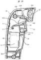
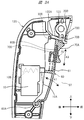
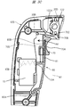
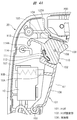
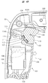
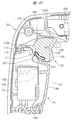
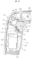
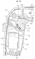
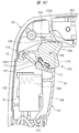
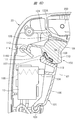
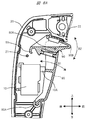
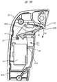
- fixed part which are provided in a power tool, and is a sectional view in which a trigger is in the 1st state. It is the specific example 3 of the trigger provided in a power tool and a trigger fixing
- FIG. 5 is a cross-sectional view showing an example of a trigger and a trigger fixing portion in a power tool that is a comparative example examined by the present applicant, and in which the trigger is in a first state.
- FIG. 1 is a cross-sectional view showing the configuration of the power tool 100.
- the power tool 100 is a hammer.
- the power tool 100 includes a main body 1, and the main body 1 includes a motor case 1A, a handle 20, a hammer case 1B, a gear case 1C, and a control case 1D.
- the motor case 1A is fixed to the gear case 1C
- the hammer case 1B is fixed to the gear case 1C.
- the control case 1D is fixed to the motor case 1A.
- the handle 20A has a first connection portion 20D and a second connection portion 20E, the first connection portion 20D is connected to the gear case 1C, and the second connection portion 20E is connected to the control case 1D.
- a space 97 is formed between the handle 20 and the motor case 1A.
- a power cable 20F is connected to the handle 20, and the power cable 20F is connected to or disconnected from the AC power supply via a plug.
- a control unit 141 is provided in the control case 1D.
- the control unit 141 is a microcomputer having a calculation unit and a storage unit.
- the electric motor 50 as a power source is provided in the motor case 1A.
- the electric motor 50 includes a rotor 50A and a stator 50B.
- the stator 50B has a coil for energization, and the coil is connected to a power source via an inverter circuit.
- the control unit 141 connects or disconnects the inverter circuit.
- the rotating shaft 51 is fixed to the rotor 50A.
- the rotation shaft 51 is rotatable around the center line D1.
- the rotational force of the rotating shaft 51 is transmitted to the crank mechanism 56 via the speed reduction mechanism 55.
- the speed reduction mechanism 55 and the crank mechanism 56 are provided in the gear case 1C.
- the crank mechanism 56 is connected to the piston 53, and the piston 53 is disposed in the cylinder 52.
- the cylinder 52 is provided in the hammer case 1B.
- the piston 53 is movable in the direction of the center line D2 of the cylinder 52.
- the crank mechanism 56 converts the rotational force of the rotating shaft 51 into the reciprocating motion force of the piston 53.
- a striker 57 is provided in the cylinder 52, and a pneumatic chamber 58 is formed between the striker 57 and the piston 53. Due to the operation of the piston 53, the pressure in the pneumatic chamber 58 rises, and the striker 57 is hit.
- a cylindrical tool holding portion 54 is provided in the hammer case 1B, and the intermediate striker 59 and the tip tool are held by the tool holding portion 54.
- the striking force of the striker 57 is transmitted to the tip tool via the intermediate striker 59, and a forward striking force is applied to the tip tool.
- the front-rear direction of the power tool 100 is a direction along the center line D2 or a direction parallel to the center line D2.
- the vertical direction of the power tool 100 is a direction along the center line D1 or a direction parallel to the center line D1.
- the center line D2 and the center line D1 are arranged so as to intersect at a right angle.
- the motor case 1A is disposed between the hammer case 1B and the handle 20 in the front-rear direction of the power tool 100, that is, in the direction of the center line D2.
- the handle 20 is disposed in a direction along the center line D1.
- a first connection portion 20 ⁇ / b> D is provided at a first end portion in the longitudinal direction of the handle 20, and a second connection portion 20 ⁇ / b> E is provided at a second end portion in the longitudinal direction of the handle 20.
- the first connection portion 20D and the second connection portion 20E are arranged with a space in the direction of the center line D1.
- the handle 20 is attached to the rear of the control case 1D and the gear case 1C in the front-rear direction of the main body 1. Specific examples of the structure inside the handle 20 will be sequentially described.
- the switch 10 is provided in the handle 20.
- the switch 10 outputs an on / off signal, and the signal of the switch 10 is input to the control unit 141.
- the control unit 141 connects an inverter circuit. Then, a voltage is applied to the electric motor 50 via the power cable 20F, and the electric motor 50 is driven, that is, rotated.
- the control unit 141 shuts off the inverter circuit. Then, no voltage is applied to the electric motor 50, and the electric motor 50 stops.
- the switch 10 includes a switch pin 10A and an elastic member 10B.
- the switch pin 10A is movable in the front-rear direction, and the elastic member 10B biases the switch pin 10A forward.
- the elastic member 10B is, for example, a metal spring.
- a trigger 30 for switching on / off of the switch 10 is provided in front of the switch 10.
- a part of the trigger 30 is disposed in the handle 20, and a part of the trigger 30 is exposed forward from the surface of the handle 20 and is located in the space 97.
- the switch 10 is turned on.
- a trigger fixing unit 40 is provided that holds the trigger 30 in a state in which the switch 10 is turned on.
- the trigger fixing portion 40 is provided on the upper side of the trigger 30 so as to be exposed forward from the surface of the handle 20 similarly to the trigger 30.
- the trigger 30 and the trigger fixing unit 40 can be operated with a finger while the user holds the handle 20 with his / her hand.
- the trigger 30 is held in the second state corresponding to the stop of the electric motor 50 when no operating force is input.
- an operating force is applied to the trigger 30, that is, when pulled backward in FIG. 2A
- the trigger 30 and the switch pin 10A of the switch 10 come into contact with each other, and the switch pin 10A is pushed rearward.
- the switch 10 is turned on.
- the switch pin 10A is urged forward, and the switch 10 is turned off when no external force is applied to the switch pin 10A.
- the position where the switch 10 is turned on at the position of the trigger 30 is the first state corresponding to the driving of the electric motor 50.
- FIG. 2A shows a state in which no external force is applied to the trigger 30 and the trigger fixing portion 40.
- the first rotation shaft 30 ⁇ / b> A is provided below the switch 10.
- the trigger 30 is rotatable with respect to the handle 20 as indicated by an arrow A1 around the first rotation shaft 30A.
- the longitudinal direction of the first rotating shaft 30A is the direction perpendicular to the paper surface in FIGS. 1, 2A, 2B, and 2C.
- the first rotation shaft 30 ⁇ / b> A may be provided on the handle 20 or may be provided on the trigger 30.
- An engagement portion 30B is provided at the end of the trigger 30 opposite to the first rotation shaft 30A. Further, the first connecting portion 20D of the handle 20 is provided with a stepped portion 122A, and the engaging portion 30B can contact and separate from the stepped portion 122A.
- the switch pin 10A is pressed against the trigger 30, and the trigger 30 is urged clockwise in FIGS. 2A, 2B, and 2C. When the user is not operating the trigger 30, the switch 10 is off, and the engagement portion 30B comes into contact with the stepped portion 122A and the trigger 30 stops. The position of the trigger 30 at which the switch 10 is turned off is the second state.
- fixed part 40 is attached to the trigger 30, and the trigger fixing
- the second rotation shaft 40A is provided between the first rotation shaft 30A and the engaging portion 30B.
- the second rotation shaft 40 ⁇ / b> A may be provided on either the trigger fixing unit 40 or the trigger 30.
- the second rotation shaft 40A is parallel to the first rotation shaft 30A.
- a hook 41 is provided at the rear end of the trigger fixing portion 40, and the handle 20 is provided with a pin 21 to which the hook 41 can be engaged and released. As shown in FIG. 2A, when the trigger 30 is held in the second state, the hook 41 is released from the pin 21.
- a spring 31 is provided between the trigger 30 and the trigger fixing portion 40.
- the spring 31 is a compression spring that expands and contracts in the front-rear direction.
- the spring 31 has a first end in the expansion / contraction direction that is in contact with the trigger 30 and a second end in the expansion / contraction direction is in contact with the trigger fixing portion 40. For this reason, the trigger fixing portion 40 is biased counterclockwise by the spring 31.
- a trigger fixing portion support portion 32 is provided on the trigger 30.
- the trigger fixing portion distal end portion 40B which is the front end portion of the trigger fixing portion 40, is engaged with the trigger fixing portion support portion 32, and the trigger fixing portion 40 is engaged. Stops with respect to the trigger 30. In this state, the trigger 30 protrudes forward from the front side of the handle 20, and the trigger fixing portion 40 protrudes further forward than the trigger 30.
- FIG. 2B shows a state where the user does not operate the trigger fixing unit 40 and operates only the trigger 30 and pulls the trigger 30 backward.
- the positional relationship of the trigger fixing portion 40 with respect to the trigger 30 does not change, and the trigger 30 rotates counterclockwise in FIG. 2A against the biasing force of the elastic member 10B.
- the fixed part 40 moves backward and tilts backward. For this reason, the hook 41 moves backward.
- the hook 41 can be engaged with the pin 21 as shown in FIG. 2B.
- the pin 21 engages with the hook 41 and the trigger fixing portion 40 is fixed, so the trigger 30 is fixed together with the trigger fixing portion 40. That is, the trigger 30 is held in the first state.
- FIG. 2C shows a state in which the trigger 30 rotates counterclockwise from the state of FIG. 2A and at the same time the trigger fixing unit 40 rotates clockwise with respect to the trigger 30.
- the state of the trigger 30 shown in FIG. 2C is the same as the state of the trigger 30 shown in FIG. 2B.
- the trigger fixing part 40 is in a state of being rotated clockwise from the state of FIG. 2A. Therefore, the position of the hook 41 shown in FIG. 2C is higher than the position of the hook 41 shown in FIG. 2B, and the hook 41 is not engaged with the pin 21. Therefore, when the user releases the trigger 30 and the trigger fixing unit 40 in the state of FIG. 2C, the switch 10 is turned off and the trigger 30 and the trigger fixing unit 40 return to the state of FIG. 2A. As described above, when the user releases the trigger 30 and the trigger fixing unit 40 in the state of FIG. 2C, the trigger 30 is switched from the first state to the second state.
- the trigger 30 When the trigger 30 is held in the first state as shown in FIG. 2B, in order to cancel the function of holding the trigger 30 in the first state, the trigger 30 is pulled backward from the state shown in FIG. It is necessary to rotate the trigger fixing part 40 clockwise.
- the switch pin 10A can be moved slightly backward, and the trigger 30 has a margin for pulling. For this reason, the trigger 30 can be pulled backward from the first state.
- the trigger fixing part 40 may be pulled backward. By this operation, the hook 41 moves rearward and upward from the state of FIG. 2B, so that the hook 41 is released from the pin 21.
- the trigger 30 and the trigger fixing unit 40 are in the state of FIG. 2A, and the switch 10 is turned off. Further, the engaging portion 30B comes into contact with the stepped portion 122A, and the trigger 30 stops in the second state.
- the hook 41 is not released from the pin 21. For this reason, the trigger 30 cannot be switched from the first state to the second state. Further, by increasing the elastic force of the spring 31 that biases the trigger fixing portion 40, the hook 41 can be prevented from being released from the pin 21 even if a weak force is applied to the trigger 30.
- the trigger 30 and the trigger fixing portion 40 are in the state shown in FIG. 2B, the trigger 41 is released from the pin 21 by operating the trigger 30 backward and simultaneously rotating the trigger fixing portion 40 clockwise. Is done. For this reason, the trigger 30 can be switched from the first state to the second state.
- the relative position of the trigger 30 and the trigger fixing portion 40 that is, the angle of the trigger fixing portion 40 around the second rotation shaft 40A is the same as in the case of FIG. It is not different from the case of FIG. 2B in which the switch 10 is on.
- the trigger 30 when the trigger 30 is in the state of FIG. 2A and the switch 10 is OFF, the trigger 30 is stopped in the second state.
- the trigger 30 when the trigger 30 is in the state of FIG. 2B and the switch 10 is turned on, the trigger 30 is held in the first state.
- the relative positions of the trigger 30 and the trigger fixing unit 40 are as follows, as shown in FIG. 2B, when the switch 10 is turned on and the trigger 30 is held in the first state, and when the switch 10 is turned on. This is different from the case of FIG. 2C in which the trigger 30 is not held in the first state.
- the trigger 30 is held in the first state when the position of the trigger fixing portion 40 with respect to the trigger 30 is in the state shown in FIG. 2B. That is, when the user does not touch the trigger fixing unit 40 and operates only the trigger 30 to turn on the switch 10, the trigger 30 is automatically fixed in the first state. On the other hand, even when the switch 10 is on, the trigger 30 is not held in the first state when the position of the trigger fixing unit 40 with respect to the trigger 30 is in the state shown in FIG. 2C.
- the trigger 30 when the user operates the trigger fixing unit 40 to turn on the switch 10 or when both the trigger fixing unit 40 and the trigger 30 are operated to turn on the switch 10, the trigger 30 is in the first state. If the user releases the trigger 30 and the trigger fixing portion 40 without being fixed to the trigger 30, the trigger 30 returns to the second state by the urging force of the elastic member 10 ⁇ / b> B.
- the trigger 30 When the hook 41 is engaged with the pin 21, the trigger 30 is held in the first state. When the hook 41 is engaged with the pin 21, the state of the trigger fixing portion 40 is a locked state. When the hook 41 is released from the pin 21, the trigger 30 can be switched between the first state and the second state. When the hook 41 is released from the pin 21, the state of the trigger fixing unit 40 is an unlocked state.
- FIGS. 3A, 3B, and 3C Specific example 2 of the structure for attaching the trigger and the trigger fixing portion to the handle is shown in FIGS. 3A, 3B, and 3C.
- the handle 120 used here is attached to the motor case 1A.
- the handle 120 is provided with the switch 10 and the trigger 60.
- the handle 120 includes a trigger fixing part support part 122 and a step part 122A.
- the trigger 60 is rotatable about the first rotation shaft 60A as indicated by an arrow A1.
- the trigger 60 has an engagement portion 30B at the end opposite to the first rotation shaft 60A in the longitudinal direction. When the trigger 60 rotates, the engaging portion 30B contacts or separates from the stepped portion 122A.
- a trigger fixing unit 70 is attached to the trigger 60.
- the trigger fixing unit 70 is attached to the trigger 60 so as to be movable in the vertical direction.
- the trigger 60 is provided with a guide rail 60 ⁇ / b> B, and the trigger fixing portion 70 is provided with a guide groove 70 ⁇ / b> D.
- the guide rail 60B is disposed in the guide groove 70D.
- the trigger fixing part 70 is movable in the direction of arrow A3 in FIG. 3A, that is, in the longitudinal direction of the trigger 60. In FIG. 3A, the trigger fixing portion 70 is movable in a direction intersecting with the front-rear direction, which is the moving direction of the trigger 60.
- a spring 61 is provided between the trigger fixing portion 70 and the trigger 60.
- the trigger fixing portion 70 is biased toward the upper side in FIG. 3A by the spring 61, that is, toward the trigger fixing portion supporting portion 122.
- fixed part 70 has 70A of trigger fixing
- the trigger fixing portion 70 has a trigger fixing portion upper surface 70B, and a stepped portion 70C that protrudes upward is connected to the rear of the trigger fixing portion upper surface 70B.
- the switch pin 10A When no operating force is applied to the trigger 60 shown in FIG. 3A, the switch pin 10A is pressed against the trigger 60, the engaging portion 30B contacts the stepped portion 122A, and the trigger 60 is stopped. That is, the switch 10 is off and the trigger 60 is held in the second state. Further, the trigger fixing portion 70 is pressed against the trigger fixing portion supporting portion 122 by the urging force of the spring 61 and is stopped.
- the trigger fixing portion upper surface 70B becomes the trigger fixing portion support portion. Move along 122.
- the switch 10 is turned on. If the step portion 70C moves to the rear of the step portion 122A in the process in which the trigger 60 rotates counterclockwise, the trigger fixing portion 70 moves upward by the biasing force of the spring 61.
- the stepped portion 70C engages with the stepped portion 122A. For this reason, the trigger 60 does not rotate clockwise from the state of FIG. 3B, and the switch 10 is maintained in the ON state. That is, the trigger 60 is held in the first state. Further, when the stepped portion 70C is engaged with the stepped portion 122A, the state of the trigger fixing portion 70 is a locked state.
- the trigger 60 When the trigger 60 is held in the first state as shown in FIG. 3B, even if only the trigger 60 is pulled backward, the trigger 60 does not switch from the first state to the second state. In contrast, when the user puts his finger on the trigger fixing portion front surface 70A and moves the trigger fixing portion 70 downward in FIG. 3B against the biasing force of the spring 61, the step portion 70C is released from the step portion 122A. Is done. When the user lifts his / her finger from the trigger fixing portion 70 and the trigger 60 with the stepped portion 70C released from the stepped portion 122A, the trigger 60 is rotated clockwise in FIG. 3B by the biasing force of the elastic member 10B. The switch 10 is turned off.
- the trigger 60 will stop in a 1st state.
- the state of the trigger fixing unit 70 is an unlocked state.
- the trigger 60 when the trigger 60 is in the state shown in FIG. 3B, the trigger 60 is urged forward by the elastic member 10B. And a frictional force arises in the contact location of level difference part 70C and level difference part 122A. As shown in FIG. 3B, a large force is required to move the trigger fixing portion 70 downward while the stepped portion 70C is locked to the stepped portion 122A. For this reason, when the force applied downward with respect to the trigger fixing
- FIG. 3A shows an example in which the user operates the trigger fixing unit 70 by placing a finger on the trigger fixing unit front surface 70A and switches the trigger 60 from the second state to the first state.
- the trigger fixing portion 70 When the user's finger is on the trigger fixing portion front surface 70 ⁇ / b> A, the trigger fixing portion 70 does not move due to the urging force of the spring 61. Then, as shown in FIG. 3C, after the switch 10 is turned on, when the user removes his / her finger from the trigger fixing portion 70 and the trigger 60 moves forward, the trigger fixing portion 70 is moved as shown in FIG. 3B. Before moving upward, the biasing force of the elastic member 10B and the positional relationship between the stepped portion 70C and the stepped portion 122A can be set so that the stepped portion 70C is positioned forward of the stepped portion 122A.
- the trigger 60 when the user removes his / her finger from the trigger fixing portion 70, the trigger 60 is rotated clockwise in FIG. 3C by the urging force of the elastic member 10B, and the switch 10 is turned off. That is, even if the user moves the trigger 60 to the first state, the trigger 60 automatically returns to the second state by the urging force of the elastic member 10B if the finger is released from the trigger fixing portion front surface 70A.
- the trigger 60 when the trigger 60 is in the first state and the trigger fixing portion 70 is in the locked state, the trigger 60 is held in the first state. Is done. On the other hand, even when the trigger 60 is in the first state, if the trigger fixing unit 70 is in the unlocked state, the trigger 60 is allowed to switch from the first state to the second state.
- the same operation as that of the power tool 100 is possible.
- the trigger 60 is fixed to the first state as shown in FIG. 3B
- the trigger 60 is pulled backward and the trigger fixing unit It is necessary to move 70 against the spring 61 downward.
- the trigger 60 is not switched from the first state to the second state to the extent that only the trigger 60 is touched or the trigger fixing portion 70 is lightly touched. Therefore, the possibility that the fixing of the trigger 60 in the first state is erroneously released can be reduced.
- the structure shown in FIGS. 3A and 3B can be realized without increasing the number of parts with a simple structure.
- the trigger fixing unit 40 is attached to the trigger 30.
- the trigger fixing portion 70 is attached to the trigger 60.
- the trigger fixing part having the above function and the trigger can be formed integrally.
- the operation for moving the trigger and the trigger are fixed in the first state.
- the operation can also be realized by a trigger alone.
- the first operation surface is a portion where an operation force is applied to rotate the trigger.
- the second operation surface is an operation-fixed operation surface for holding the trigger in a state in which the switch is turned on when no external force is applied to the trigger after the trigger is turned on.
- the operation fixing operation surface is the front surface of the trigger 30 below the trigger fixing portion 40 in FIG.
- the operation fixing operation surface is the front surface of the trigger 60 below the trigger fixing portion 70 in FIG.
- the first operation surface is a non-fixed operation surface in which the switch is turned off in a state where no external force is applied to the trigger 60 after the trigger 60 is operated backward and the switch 10 is turned on.
- the first operation surface in FIG. 2 is the front surface of the trigger fixing unit 40.
- a first operation surface in FIG. 3 is a trigger fixing portion front surface 70 ⁇ / b> A of the trigger fixing portion 70. That is, the above operation may be realized by providing such a fixed operation surface and a non-fixed operation surface in a single trigger.
- FIGS. 4A, 4B and 4C show a specific example 3 of the trigger 101 and the trigger fixing unit 102.
- the trigger 101 is rotatable about the first rotation shaft 103 with respect to the handle 20.
- the first rotation shaft 103 may be provided on either the trigger 101 or the handle 20.
- the trigger 101 is disposed between the first connecting portion 20 ⁇ / b> D of the handle 20 and the first rotation shaft 103.
- the switch pin 10A is pressed against the trigger 101 by the urging force of the elastic member 10B.
- the trigger 101 is biased clockwise in FIG. 4A about the first rotation shaft 103.
- the free end of the trigger 101 is disposed between the first connecting portion 20 ⁇ / b> D and the first rotation shaft 103, and the engaging portion 104 is provided at the free end of the trigger 101.
- the trigger 101 has a housing portion 105.
- the accommodating portion 105 is a space formed between the free end of the trigger 101 and the first rotation shaft 103.
- an operation unit 106 is formed between the storage unit 105 and the first rotation shaft 103.
- the operation unit 106 is a portion of the trigger 101 that is exposed to the space 97.
- a protruding portion 107 protruding from the inner surface of the accommodating portion 105 is provided.
- the trigger fixing portion 102 is disposed in the housing portion 105, and the trigger fixing portion 102 can be rotated around the second rotation shaft 108 or as a fulcrum.
- the second rotation shaft 108 may be provided on either the trigger fixing unit 102 or the trigger 101.
- a first sub operation unit 109 and a second sub operation unit 110 are provided in a portion of the trigger fixing unit 102 that is exposed to the space 97.
- the operation unit 106, the first sub operation unit 109, and the second sub operation unit 110 are provided in the longitudinal direction of the trigger 101.
- the second sub operation unit 110 is arranged between the operation unit 106 and the first sub operation unit 109 in the longitudinal direction of the trigger 101.
- An elastic member, for example, a metal leaf spring 111 is attached to the trigger fixing portion 102.
- the leaf spring 111 has a protruding portion 112, and the protruding portion 112 gets over the protruding portion 107 when the trigger fixing portion 102 rotates around the second rotating shaft 108.
- the trigger fixing part 102 has a hook 113.
- the hook 113 is disposed in the handle 20.
- the hook 113 is curved so as to approach the switch 10.
- a pin 114 is provided in the handle 20.
- the hook 113 is disposed between the first connecting portion 20D and the pin 114.
- the hook 113 can be engaged with and released from the pin 114.
- a stopper 114A connected to the pin 114 is provided.
- the stopper 114 ⁇ / b> A is extended toward the trigger fixing portion 102.
- the first connection portion 20D has a step portion 122A.
- the engaging portion 104 can contact and be separated from the stepped portion 122A.
- the engaging portion 104 is pressed against the step portion 122A, and the trigger 101 is stopped. Further, the switch 10 is turned off. That is, the trigger 101 is stopped in the second state.
- the trigger fixing portion 102 is stopped with respect to the trigger 101 in a state where the protruding portion 112 rides on the protruding portion 107.
- a state in which the trigger fixing unit 102 is stopped with respect to the trigger 101 in a state in which the protruding portion 112 rides on the protruding portion 107 is referred to as a standby state of the trigger fixing portion 102.
- the hook 113 is released from the pin 114.
- the tip of the hook 113 comes into contact with the stopper 114A, so the trigger fixing unit 102 moves the second rotation shaft 108.
- the rotation around the center is restricted, and the trigger fixing portion 102 is held in a standby state.
- the switch pin 10A resists the biasing force of the elastic member 10B as shown in FIG. 4B.
- the switch 10 is turned on. That is, the trigger 101 shown in FIG. 4B is in the first state.
- the trigger fixing unit 102 is stopped in a standby state.
- the trigger 101 When the trigger 101 is in the first state as shown in FIG. 4B and the operating force applied to the trigger 101 is reduced, the trigger 101 is rotated clockwise by the biasing force of the elastic member 10B, and the switch 10 is turned off. And if the engaging part 104 contacts the level
- the trigger fixing unit 102 rotates counterclockwise in FIG. 4B. Move. Then, the protruding portion 112 gets over the protruding portion 107, and the hook 113 engages with the pin 114 as shown in FIG. 4C, and the protruding portion 112 stops between the protruding portion 107 and the operating portion 106. Thus, the state in which the hook 113 is engaged with the pin 114 and the protruding portion 112 is stopped between the protruding portion 107 and the operating portion 106 is a locked state of the trigger fixing portion 102. The trigger fixing unit 102 is in a locked state. Regardless of the magnitude of the operating force applied to the trigger 101 by the user, the trigger 101 is held in the first state.
- the trigger fixing unit 102 rotates clockwise in FIG. 4C. Then, the protrusion 112 rides on the protrusion 107 as shown in FIG. 4B. Further, the hook 113 is released from the pin 114, and the trigger fixing unit 102 enters a standby state. Furthermore, when the operation force applied to the second sub operation unit 110 decreases or the operation force applied to the trigger 101 decreases, the trigger 101 rotates clockwise in FIG. 4B. Then, the switch 10 is turned off, and the engaging portion 104 comes into contact with the stepped portion 122A as shown in FIG. 4A, and the trigger 101 stops in the second state.
- the operation force applied to the trigger 101 increases.
- the trigger 101 is not erroneously switched from the first state to the second state.
- the trigger fixing portion 102 is attached to the trigger 101, it is not necessary to provide a release button exclusively. For this reason, while being able to enlarge the part which an operator grasps with a hand among handles 20, it can control that the whole power tool 100 enlarges.
- the operator can operate both the trigger 101 and the trigger fixing portion 102 with one hand without changing the handle 20, good operability can be realized.
- the trigger 101 can be switched between the first state and the second state by changing the operating force applied to the trigger 101. Therefore, the operability for the user is improved.
- FIGS. 5A, 5B and 5C show a specific example 4 of the trigger 101 and the trigger fixing unit 102.
- FIG. When the specific example 4 and the specific example 3 are compared, the trigger fixing unit 102 is different.
- the first sub operation unit 109 in the fourth specific example is provided between the second sub operation unit 110 and the operation unit 106.
- the hook 113 is curved in a direction away from the switch 10.
- the engaging portion 104 is pressed against the stepped portion 122A, and the trigger 101 is stopped. Further, the switch 10 is turned off.
- the protruding portion 112 is stopped between the protruding portion 107 and the operation portion 106.
- a state in which the protruding portion 112 is stopped between the protruding portion 107 and the operation portion 106 is referred to as a standby state of the trigger fixing portion 102.
- the hook 113 is released from the pin 114.
- the switch pin 10A resists the biasing force of the elastic member 10B as shown in FIG. 5B.
- the switch 10 is turned on. That is, the trigger 101 shown in FIG. 5B is in the first state.
- the trigger fixing unit 102 is stopped in a standby state.
- the trigger 101 When the trigger 101 is in the first state as shown in FIG. 5B and the operating force applied to the trigger 101 decreases, the trigger 101 rotates clockwise by the biasing force of the elastic member 10B, and the switch 10 is turned off. And the engaging part 104 contacts the level
- the hook 113 is released from the pin 114, the trigger 101 can be switched between the first state and the second state according to the magnitude of the operating force applied to the trigger 101.
- a state where the hook 113 is released from the pin 114 is an unlocked state of the trigger fixing unit 102.
- the trigger fixing unit 102 rotates clockwise in FIG. 5B. Then, the protrusion 112 rides on the protrusion 107 as shown in FIG. 5C, and the hook 113 engages with the pin 114. Thus, the state in which the hook 113 is engaged with the pin 114 and the protruding portion 112 has stopped over the protruding portion 107 is the locked state of the trigger fixing portion 102. The trigger fixing unit 102 is in a locked state. Regardless of the magnitude of the operating force applied to the trigger 101, the trigger 101 is held in the first state.
- the trigger fixing unit 102 rotates counterclockwise. Then, the protruding portion 112 gets over the protruding portion 107, and the trigger fixing portion 102 enters a standby state as shown in FIG. 5B. Further, the hook 113 is released from the pin 114. Furthermore, when the operation force applied to the second sub operation unit 110 decreases or the operation force applied to the trigger 101 decreases, the trigger 101 rotates clockwise in FIG. 5B. Then, the switch 10 is turned off, and the engaging portion 104 contacts the stepped portion 122A as shown in FIG. 5A, and the trigger 101 stops in the second state.
- the operation force applied to the trigger 101 increases. Even in this case, the trigger 101 is not erroneously switched from the first state to the second state. Further, since the trigger fixing portion 102 is attached to the trigger 101, it is not necessary to provide a release button exclusively. For this reason, while being able to enlarge the part which an operator grasps with a hand among handles 20, it can control that the whole power tool 100 enlarges. In addition, since the operator can operate both the trigger 101 and the trigger fixing portion 102 with one hand without changing the handle 20, good operability can be realized.
- the trigger 101 can be switched between the first state and the second state by changing the operating force applied to the trigger 101. Therefore, the operability for the user is improved.
- FIGS. 6A, 6B, 6C, and 6D show a specific example 5 of the trigger 101 and the trigger fixing unit 102.
- FIG. When the specific example 5 is compared with the specific example 3, the position of the stopper 114A is different.
- the stopper 114 ⁇ / b> A is inclined downward from the pin 114, specifically in a direction approaching the switch 10.
- the operations of the trigger 101 and the trigger fixing unit 102 in the specific example 5 are the same as the operations of the trigger 101 and the trigger fixing unit 102 in the specific example 3.
- the trigger 101 is stopped and the switch 10 is turned off. That is, the trigger 101 is stopped in the second state.
- the trigger fixing unit 102 is in a standby state.
- the trigger 101 rotates clockwise and the switch 10 is turned off, and the trigger 101 is in the second state shown in FIG. 6A. Stop at.
- the hook 113 is released from the pin 114, the trigger 101 can be switched between the first state and the second state according to the magnitude of the operating force applied to the trigger 101.
- the trigger 101 When the trigger 101 is in the first state as shown in FIG. 6B, when the user applies an operation force to the first sub operation unit 109, the trigger fixing unit 102 rotates counterclockwise, and the protrusion 112 is illustrated in FIG. Get over the protrusion 107 as in 6C. Further, the hook 113 engages with the pin 114, and the protruding portion 112 stops between the protruding portion 107 and the operation portion 106. As described above, when the hook 113 is engaged with the pin 114, the trigger 101 is held in the first state regardless of the magnitude of the operation force applied to the trigger 101.
- the trigger 101 When the trigger 101 is held in the first state as shown in FIG. 6C, when the user applies an operation force to the second sub operation unit 110, the trigger fixing unit 102 rotates clockwise. Then, the hook 113 is released from the pin 114 as shown in FIG. 6B. Further, when the operation force applied to the second sub operation unit 110 decreases or the operation force applied to the trigger 101 decreases, the trigger 101 rotates clockwise in FIG. 6B and the switch 10 is turned off. Stops in the second state shown in FIG. 6A.
- the fifth specific example of the trigger 101 and the trigger fixing unit 102 can obtain the same effect as the third specific example of the trigger 101 and the trigger fixing unit 102.
- Specific example 5 of the trigger 101 and the trigger fixing unit 102 is that when the user applies an operating force to the first sub operation unit 109 while the trigger 101 is stopped in the second state shown in FIG. 6A, the trigger fixing unit 102 rotates counterclockwise about the second rotation shaft 108. For this reason, the protrusion part 112 gets over the protrusion part 107 like FIG. 6D. Further, the tip of the hook 113 comes into contact with the stopper 114A, and the trigger fixing portion 102 stops. The trigger 101 is stopped in the second state, and the switch 10 is turned off.
- the trigger 101 rotates counterclockwise in FIG. 6D, and the switch 10 is turned on. Further, in the process in which the trigger 101 rotates counterclockwise in FIG. 6D, the hook 113 slides while being in contact with the stopper 114A. For this reason, the trigger fixing portion 102 rotates clockwise in FIG. 6D, and the hook 113 is biased in a direction away from the switch 10. By this action, the protruding portion 112 gets over the protruding portion 107 as shown in FIG. 6B, and the trigger fixing portion 102 stops.
- the trigger fixing unit 102 when the trigger fixing unit 102 is stopped as shown in FIG. 6B, the operating force applied to the trigger 101 decreases or the operating force applied to the second sub operating unit 110 decreases.
- the trigger 101 rotates clockwise in FIG. 6B, the switch 10 is turned off, and the trigger 101 stops in the second state shown in FIG. 6A.
- the trigger 101 and the trigger fixing unit 102 first, an operating force is applied to the first sub operation unit 109 of the trigger fixing unit 102, and the trigger fixing unit 102 is rotated counterclockwise in FIG. 6A.
- the trigger fixing part 102 can be brought into the state shown in FIG. 6D.
- the user can operate the trigger 101 to turn on the switch 10. Therefore, the options that can be operated by the user increase.
- the trigger fixing portion 102 has a holding hole 115, and a contactor 116 is movably provided in the holding hole 115.
- the contact 116 is movable in the radial direction around the second rotation shaft 108.
- a spring 117 is provided in the holding hole 115, and the spring 117 is a compression spring. The spring 117 urges the contact 116 toward the protruding portion 107.
- the switch 10 When the user does not operate the trigger 101 and the trigger fixing unit 102, the switch 10 is turned off and the trigger 101 is stopped in the second state.
- the trigger fixing portion 102 is stopped with respect to the trigger 101 in a state where the contactor 116 rides on the protruding portion 107.
- a state in which the trigger fixing unit 102 is stopped with respect to the trigger 101 in a state where the contactor 116 rides on the protruding portion 107 is referred to as a standby state of the trigger fixing unit 102.
- the hook 113 is released from the pin 114.
- the trigger 101 rotates clockwise, the switch 10 is turned off, and the trigger 101 stops in the second state.
- the hook 113 is released from the pin 114, the trigger 101 can be switched between the first state and the second state according to the magnitude of the operating force applied to the trigger 101.
- the trigger fixing unit 102 rotates counterclockwise. Then, the contact 116 gets over the protruding portion 107, the hook 113 engages with the pin 114, and the contact 116 stops between the protruding portion 107 and the operation portion 106.
- the state in which the hook 113 is engaged with the pin 114 and the contactor 116 is stopped between the protruding portion 107 and the operation portion 106 is a locked state of the trigger fixing portion 102.
- the trigger fixing unit 102 is in a locked state. Regardless of the magnitude of the operating force applied to the trigger 101, the trigger 101 is held in the first state.
- the trigger fixing unit 102 rotates clockwise. Then, the contact 116 gets over the protruding portion 107, the hook 113 is released from the pin 114, and the trigger fixing portion 102 enters a standby state. Further, when the operation force applied to the second sub operation unit 110 decreases or the operation force applied to the trigger 101 decreases, the trigger 101 rotates clockwise. Then, the switch 10 is turned off, and the trigger 101 stops in the second state.
- the specific example 6 of the trigger 101 and the trigger fixing unit 102 has the same effect as the specific example 3 of the trigger 101 and the trigger fixing unit 102.
- the electric motor 50 is an example of a power source
- the second rotation shafts 40A and 108 the guide rail 60B is an example of a support portion
- the first rotation shafts 30A, 60A, and 103 are rotation shafts.
- the second rotation shafts 40A and 108 are examples of support shafts.
- the power tool is not limited to the above embodiment, and can be variously changed without departing from the gist thereof.
- the power tool is an electric hammer
- the power tool includes a hammer drill, a vibration drill, a driver, and a drill.
- Tip tools that operate with the power of the power source include those that reciprocate linearly, those that rotate, those that receive a striking force in the rotational direction, and those who receive a straight striking force.
- the power source of the power tool is not limited to the electric motor, but includes an engine, a pneumatic motor, and a hydraulic motor.
- the switches that are turned on / off by the trigger include an electric switch and a mechanical switch.
- the trigger includes a trigger provided in addition to a pivotable one and a trigger provided in a reciprocating manner.
- the trigger fixing portion includes a portion provided so as to be able to reciprocate in addition to a portion provided so as to be rotatable.
Landscapes
- Engineering & Computer Science (AREA)
- Mechanical Engineering (AREA)
- Portable Power Tools In General (AREA)
Abstract
トリガをオンに固定した状態が誤って解除されることが抑制され、かつ単純な構造の動力工具を得る。動力源を収容する本体と、本体に設けられ、かつ、使用者に操作されて本体に対して移動することで、動力源の駆動に対応する第1状態と、動力源の停止に対応する第2状態とを切り替え可能なトリガ(101)と、を備えた動力工具であって、トリガ(101)を第1状態に保持するロック状態、及びトリガ(101)が第1状態と前記第2状態とで切り替わることを許容するアンロック状態を有するトリガ固定部(102)と、トリガ(101)とトリガ固定部(102)とを接続し、トリガ固定部(102)をロック状態とアンロック状態で切り替え可能に支持する支持部(108)と、を有し、トリガ固定部(102)のロック状態からアンロック状態への切り替えは、使用者がトリガ固定部(102)を操作することで行われる。
Description
本発明は、トリガを操作することによって動力源の駆動及び停止が制御される動力工具の構造に関する。
ハンマやハンマドリル等の動力工具は、本体内に設けた動力源と、動力源の動力で動作する先端工具と、動力源の駆動及び停止を切り替えるトリガと、を有する。使用者がハンドルを手で把持した状態で、ハンドルに装着されたトリガを指で操作すると、動力源を駆動及び停止可能である。動力源が駆動すると、本体の先端に設けられた作業部材を動作させることができる。トリガは、動力源を駆動させるための第1状態と、動力源を停止させるための第2状態とで切り替え可能である。使用者がトリガに操作力を加えない限り、トリガは第2状態に保持される。
一方、作業の内容によっては、動力源を長時間に亘って駆動し続ける場合がある。こうした場合のために、トリガを第1状態に固定するためのロック機構が設けられる。ロック機構を有する動力工具は、例えば、特許文献1に記載されている。
特許文献1に記載された動力工具は、トリガを操作すると、ハンドル内に設けられたスイッチがオンし、動力源が駆動する。また、ハンドルにロックレバーが設けられ、ロックレバーを操作すると、トリガに加わる操作力が解除された後も、トリガは、スイッチのオンが維持されるように、第1状態に維持される。そして、解除ボタンを押すと、ロックレバーが元の位置にもどり、スイッチがオフされ、かつ、トリガは第2状態に戻る。
また、ロック機構と、トリガと組み合わせた構成を有する動力工具のハンドルの構造を図8A、図8Bに示す。図8A、図8Bに示すハンドルの構造は、本出願人が検討した比較例である。図8Aは、使用者がトリガを操作しておらず、トリガが第2状態、つまり、スイッチがオフで停止している例を示す。図8Bは、使用者がトリガを操作して、トリガが第1状態、つまり、スイッチがオンの状態で固定されている例を示す。ここでは、前後方向に沿った断面が示されており、前後、上下方向の向きは図示されたとおりである。
ここで、本体内に、動力工具に用いられるモータが収容されている。本体の一部を構成するハンドル20内に、モータへの電力供給のオン・オフを制御するスイッチ10が設けられている。スイッチ10には、前後方向で移動可能なように前方に突出したスイッチピン10Aが設けられている。スイッチピン10Aが前方に突出した図8Aの状態が、スイッチ10のオフである。スイッチピン10Aが前方に突出せず後方にある図8Bの状態が、スイッチ10のオンである。スイッチピン10Aは、図示しないスプリングにより前方に付勢されている。スイッチピン10Aに外力が加わらない限り、スイッチピン10Aは図8Aの状態にある。
硬質の弾性材料で構成されたトリガ80は、ハンドル20においてスイッチピン10Aの右側に設けられている。スイッチ10の下側に第1の回動軸80Aが設けられている。トリガ80は、第1の回動軸80Aを中心として、図8Aで矢印B1のようにハンドル20に対して回動可能である。この際、トリガ80は、図中時計回りに付勢されている。このため、使用者がトリガ80を図中反時計回りに操作することによって、スイッチピン10Aを後方に押し込み、図8Bに示されるようにスイッチ10をオンさせることができる。トリガ80に操作力が加わらない場合は、図8Aに示されるようにスイッチ10はオフである。
ここで、トリガ80の上部には、第2の回動軸90Aを介してトリガ固定部90が取り付けられている。トリガ固定部90は、第2の回動軸90Aを中心として、図8Aに矢印B2で示されるように、トリガ80に対して回動可能である。トリガ固定部90は、図中時計回りに付勢されている。トリガ固定部90の左端にはフック91が設けられ、ハンドル20には、フック91が係合可能である。図中、紙面の垂直方向に延伸するピン21が設けられている。図8Aの状態においては、フック91はピン21に係合しておらず、ピン21から離間している。また、図8Aの状態で、トリガ80の上部はハンドル20の上部に設けられたトリガ支持部22に係止されて支持される。
図8Aの状態から、使用者がトリガ80を操作して反時計回りに回動させ、かつ、トリガ固定部90を反時計回りに回動させることによって、図8Bに示されるように、フック91をピン21に係合させることができる。このため、トリガ80は時計回りに付勢されているものの、図8Bの状態では、トリガ固定部90のフック91がピン21に係止され、トリガ80及びトリガ固定部90は固定される。これによって、使用者がトリガ80に触れない状態で、スイッチ10のオン状態を継続させることができる。すなわち、トリガ80を第1状態で固定することができる。
一方、トリガ80を第1状態から解除するためには、トリガ80を図8Bに示す状態から、図8Bにおける矢印B3に示されるように、トリガ80に力を加えればよい。トリガ80が固定された状態でも、スイッチピン10Aは後方にわずかに移動可能であり、トリガ80に引き代がある。このため、トリガ固定部90は図で左側に移動し、かつ、トリガ固定部90は時計回りに付勢され、トリガ固定部90が、図8Bに矢印B4で示されるようにトリガ80に対して時計回りに回動する。このため、フック81がピン21から解放される。この状態で使用者がトリガ80から手を離せば、トリガ80は図中時計回りに回動し、トリガ80は、再び図8Aの状態となり、スイッチ10はオフする。上記のようにトリガ80を、スイッチ10のオンに対応する第1状態で固定せずに、トリガ80から手を離してスイッチ10をオフさせる場合、使用者は、トリガ固定部90には触れずにトリガ80のみを操作すればよい。
こうした構造によって、トリガ80を操作してモータの駆動及び停止を制御する。通常は、トリガ80から手を離した場合には、スイッチ10は自動的にオフとなる。必要に応じてトリガ80から手を離した場合にも、トリガ80を、スイッチ10がオンとなる第1状態に保持することができる。
図8A、図8Bの構成において、図8Bの状態で、使用者が誤ってトリガ80に触れた場合や、トリガ80に何かの部材が接した場合、あるいは強い振動が加わった場合には、トリガ80の固定が解除され、不意にスイッチ10がオフされることがあった。一方、特許文献1に記載の構造の場合には、こうした誤作動は発生しにくいが、トリガ以外の別部品として解除ボタンが必要であり、部品点数が多くなり構造が複雑となった。
このため、トリガをオンに固定した状態から、誤って解除されることを抑制でき、かつ単純な構造の動力工具が望まれた。
本発明は、かかる問題点に鑑みてなされたものであり、上記の問題点を解決することの可能な動力工具を提供することを目的とする。
一実施形態の動力工具は、動力源を収容する本体と、前記本体に対して移動可能に設けられ、かつ、前記動力源の駆動に対応する第1状態と、前記動力源の停止に対応する第2状態とを切り替え可能なトリガと、を備えた動力工具であって、前記トリガを前記第1状態に保持するロック状態、及び前記トリガが前記第1状態と前記第2状態とで切り替わることを許容するアンロック状態を有するトリガ固定部と、前記トリガと前記トリガ固定部とを接続し、前記トリガ固定部を前記ロック状態と前記アンロック状態で切り替え可能に支持する支持部と、を有する。
一実施形態の動力工具は、トリガを第1状態に保持する機能が、誤って解除されることを抑制でき、かつ、単純な構造の動力工具を得ることができる。
本発明の一実施形態である動力工具の構成について、図面を用いて説明する。
図1は、動力工具100の構成を示す断面図である。動力工具100は、ハンマである。動力工具100は、本体1を有し、本体1は、モータケース1A、ハンドル20、ハンマケース1B、ギヤケース1C及び制御ケース1Dを有する。モータケース1Aはギヤケース1Cに固定され、ハンマケース1Bはギヤケース1Cに固定されている。制御ケース1Dはモータケース1Aに固定されている。ハンドル20Aは、第1接続部20D及び第2接続部20Eを有し、第1接続部20Dはギヤケース1Cに接続され、第2接続部20Eは、制御ケース1Dに接続されている。ハンドル20とモータケース1Aとの間に空間97が形成されている。電力ケーブル20Fがハンドル20に接続されており、電力ケーブル20Fは、プラグを介して交流電源に接続または遮断される。制御ケース1D内に制御部141が設けられている。制御部141は、演算部、記憶部を有するマイクロコンピュータである。
モータケース1A内に、動力源としての電動モータ50が設けられている。電動モータ50は、ロータ50A及びステータ50Bを有する。ステータ50Bは、通電用のコイルを有し、コイルはインバータ回路を介して電源に接続される。制御部141はインバータ回路を接続または遮断する。回転軸51がロータ50Aに固定されている。回転軸51は、中心線D1を中心として回転可能である。回転軸51の回転力は、減速機構55を介してクランク機構56に伝達される。減速機構55およびクランク機構56は、ギヤケース1C内に設けられている。クランク機構56は、ピストン53に連結され、ピストン53はシリンダ52内に配置されている。シリンダ52は、ハンマケース1B内に設けられている。ピストン53は、シリンダ52の中心線D2方向に移動可能である。クランク機構56は、回転軸51の回転力をピストン53の往復運動力に変換する。シリンダ52内に打撃子57が設けられ、打撃子57とピストン53との間に空気圧室58が形成されている。ピストン53の動作によって空気圧室58の圧力が上昇し、打撃子57が打撃される。
ハンマケース1B内に筒形状の工具保持部54が設けられ、工具保持部54により中間打撃子59及び先端工具が保持される。打撃子57の打撃力は中間打撃子59を介して先端工具に伝達され、先端工具に前方向きの打撃力が加えられる。
動力工具100の前後方向は、中心線D2に沿った方向、もしくは中心線D2と平行な方向である。動力工具100の上下方向は、中心線D1に沿った方向、もしくは中心線D1と平行な方向である。動力工具100の側面視、つまり、中心線D2を含む側面視で、中心線D2と中心線D1とが直角に交差して配置されている。動力工具100の前後方向、つまり、中心線D2方向において、モータケース1Aは、ハンマケース1Bとハンドル20との間に配置されている。
ハンドル20は中心線D1に沿った方向に配置されている。ハンドル20における長手方向の第1端部に第1接続部20Dが設けられ、ハンドル20における長手方向の第2端部に第2接続部20Eが設けられている。第1接続部20D及び第2接続部20Eは、中心線D1方向に間隔をおいて配置されている。
この動力工具100において、ハンドル20は、本体1の前後方向で制御ケース1D及びギヤケース1Cの後方に取り付けられている。ハンドル20内の構造の具体例を、順次説明する。
(具体例1)スイッチ10がハンドル20内に設けられている。スイッチ10はオン・オフ信号を出力し、スイッチ10の信号は制御部141に入力される。スイッチ10がオンされると、制御部141はインバータ回路を接続する。すると、電力ケーブル20Fを介して電動モータ50に電圧が印加され、電動モータ50が駆動、つまり回転する。スイッチ10がオフされると、制御部141はインバータ回路を遮断する。すると、電動モータ50に電圧が印加されず、電動モータ50は停止する。
図2A、図2B及び図2Cのように、スイッチ10は、スイッチピン10A及び弾性部材10Bを有する。スイッチピン10Aは、前後方向に移動可能であり、弾性部材10Bは、スイッチピン10Aを前方に付勢する。弾性部材10Bは、例えば金属製のスプリングである。
スイッチ10の前方には、このスイッチ10のオン・オフを切り替えるためのトリガ30が設けられている。トリガ30の一部はハンドル20内に配置され、トリガ30の一部は、ハンドル20の表面から前方に露出して、空間97に位置している。トリガ30に操作力を加えて後方に移動するとスイッチ10はオンとなる。トリガ30をスイッチ10がオンされた状態に保持するトリガ固定部40が設けられている。トリガ固定部40は、トリガ30の上側において、トリガ30と同様にハンドル20の表面から前方に露出するように設けられる。使用者がハンドル20を手で把持した状態において、トリガ30やトリガ固定部40を指で操作することができる。
トリガ30は、操作力が入力されていないと、電動モータ50の停止に対応する第2状態に保持される。これに対して、トリガ30に操作力が加えられる、つまり、図2Aで後方に引かれると、トリガ30とスイッチ10におけるスイッチピン10Aとが当接し、スイッチピン10Aが後方に向けて押されることによってスイッチ10がオンとなる。スイッチピン10Aは前方に向けて付勢され、スイッチピン10Aに外力が加わらない場合にはスイッチ10はオフとなる。トリガ30の位置において、スイッチ10がオンとなる位置が、電動モータ50の駆動に対応する第1状態である。
図2Aにおいては、トリガ30及びトリガ固定部40に外力が加わらない状態が示されている。第1の回動軸30Aが、スイッチ10よりも下側に設けられている。トリガ30は、第1の回動軸30Aを中心として、ハンドル20に対して矢印A1で示されるように回動可能である。第1の回動軸30Aの長手方向は、図1、図2A、図2B及び図2Cにおいて紙面の垂直方向である。第1の回動軸30Aは、ハンドル20に設けらていてもよいし、トリガ30に設けられていてもよい。
トリガ30のうち、第1の回動軸30Aとは反対の端部に係合部30Bが設けられている。また、ハンドル20の第1接続部20Dに段差部122Aが設けられており、係合部30Bは段差部122Aに接触及び離間可能である。スイッチピン10Aはトリガ30に押し付けられており、トリガ30は図2A、図2B、図2Cで時計回りに付勢される。使用者がトリガ30を操作していない場合、スイッチ10はオフであり、かつ、係合部30Bが段差部122Aに接触してトリガ30が停止する。スイッチ10がオフされるようなトリガ30の位置が、第2状態である。
また、トリガ固定部40はトリガ30に取り付けられており、トリガ固定部40は、第2の回動軸40Aを中心として矢印A2で示されるように回動可能である。第2の回動軸40Aは、第1の回動軸30Aと係合部30Bとの間に設けられている。第2の回動軸40Aは、トリガ固定部40またはトリガ30の何れに設けられていてもよい。第2の回動軸40Aは第1の回動軸30Aと平行である。
また、フック41がトリガ固定部40の後端に設けられ、ハンドル20には、フック41が係合及び解放可能なピン21が設けられている。図2Aのように、トリガ30が第2状態に保持されていると、フック41はピン21から解放されている。
さらに、トリガ30とトリガ固定部40との間にスプリング31が設けられている。スプリング31は、前後方向に伸縮する圧縮スプリングである。スプリング31は、伸縮方向の第1端部がトリガ30に接触し、伸縮方向の第2端部がトリガ固定部40に接触している。このため、トリガ固定部40は、スプリング31により反時計回りに付勢されている。トリガ30の上部にトリガ固定部支持部32が設けられている。
図2Aのようにトリガ固定部40に外力が加わらない状態では、トリガ固定部40の前端の部分であるトリガ固定部先端部40Bが、トリガ固定部支持部32に係合し、トリガ固定部40がトリガ30に対して停止する。この状態において、トリガ30はハンドル20の前面側から前方に突出し、トリガ固定部40はトリガ30よりも更に前方に突出する。
この状態で、使用者がトリガ固定部40を操作せず、トリガ30のみを操作してトリガ30を後方に引いた状態が図2Bである。トリガ30のみを操作すると、トリガ固定部40のトリガ30に対する位置関係が変わらず、かつ、トリガ30が、弾性部材10Bの付勢力に抗して図2Aで反時計回りに回動するため、トリガ固定部40は後方に移動し、かつ、後方に傾斜する。このため、フック41が後方に移動する。
この状態で使用者がトリガ30から手を離せば、図2Bに示されるように、フック41をピン21に係合させることができる。使用者がトリガ30から手を離した場合において、ピン21がフック41に係合してトリガ固定部40が固定されるため、トリガ固定部40と共にトリガ30も固定される。すなわち、トリガ30が第1状態で保持される。
一方、使用者が図2Aの状態にあるトリガ固定部40を後方に引いた場合にも、トリガ30を図2Aで反時計回りに回動させることができる。また、使用者が、トリガ30とトリガ固定部40の境界部分に触れて、トリガ30及びトリガ固定部40を同時に後方に引いた場合も、トリガ30を図2Aで反時計回りに回動させることができる。このように、トリガ30が図2Aの状態から反時計回りに回動すると同時に、トリガ固定部40がトリガ30に対して時計回りに回動した状態が、図2Cである。
図2Cに示すトリガ30の状態は、図2Bに示すトリガ30の状態と同じである。しかし、トリガ固定部40は、図2Aの状態よりも時計回りに回動した状態にある。このため、図2Cに示すフック41の位置は、図2Bに示すフック41の位置よりも上であり、フック41はピン21に係合していない。このため、使用者が、図2Cの状態にあるトリガ30及びトリガ固定部40から手を離すと、スイッチ10はオフされ、かつ、トリガ30及びトリガ固定部40は図2Aの状態に戻る。このように、使用者が、図2Cの状態にあるトリガ30及びトリガ固定部40から手を離すと、トリガ30は第1状態から第2状態に切り替わる。
なお、トリガ30が図2Bのように第1状態に保持されている際、トリガ30を第1状態に保持する機能を解除するためには、図2Bの状態からトリガ30を後方に引き、かつトリガ固定部40を時計回りに回動させることが必要である。ここで、トリガ30が第1状態に保持されている際でも、スイッチピン10Aは後方にわずかに移動可能であり、トリガ30は引き代がある。このため、トリガ30を第1状態から後方に引くことができる。また、トリガ固定部40を時計回りに回動させるためには、トリガ固定部40を後方に引けばよい。この操作によって、フック41が図2Bの状態から、後方かつ上方に移動するため、フック41がピン21から解放される。その後、使用者がトリガ30及びトリガ固定部40から手を離せば、トリガ30及びトリガ固定部40は図2Aの状態となり、スイッチ10はオフとなる。また、係合部30Bが段差部122Aに接触し、トリガ30は第2状態で停止する。
これに対して、トリガ30及びトリガ固定部40が図2Bの状態にある際に、トリガ30のみを操作しても、フック41がピン21から解放されない。このため、トリガ30を第1状態から第2状態に切り替えることはできない。また、トリガ固定部40を付勢するスプリング31の弾性力を強くすることで、トリガ30に弱い力が加わったとしても、フック41がピン21から解放されないようにすることもできる。
これに対し、トリガ30及びトリガ固定部40が図2Bの状態にある際に、トリガ30を後方に操作すると同時に、トリガ固定部40を時計回りに回動させると、フック41がピン21から解放される。このため、トリガ30を第1状態から第2状態に切り替えることができる。
上記の動作において、トリガ30とトリガ固定部40の相対的な位置、つまり、第2の回動軸40Aの周りにおけるトリガ固定部40の角度は、スイッチ10がオフである図2Aの場合と、スイッチ10がオンである図2Bの場合とで変わらない。ここで、トリガ30が図2Aの状態にあり、スイッチ10がオフである場合は、トリガ30は第2状態で停止している。これに対して、トリガ30が図2Bの状態となりスイッチ10がオンとされた場合に、トリガ30は第1状態に保持される。
一方、トリガ30とトリガ固定部40の相対的な位置は、図2Bのように、スイッチ10がオンとなり、かつ、トリガ30が第1状態に保持される場合と、スイッチ10がオンとなり、かつ、トリガ30が第1状態に保持されない図2Cの場合と、で異なる。
すなわち、この動力工具100においては、スイッチ10がオンである際、トリガ30に対するトリガ固定部40の位置が、図2Bの状態にある場合には、トリガ30は第1状態に保持される。つまり、使用者がトリガ固定部40には触れず、トリガ30のみを操作してスイッチ10をオンとした場合は、自動的にトリガ30は第1状態で固定される。こに対して、スイッチ10がオンである場合でも、トリガ30に対するトリガ固定部40の位置が図2Cの状態にある場合は、トリガ30は第1状態に保持されない。
一方、使用者がトリガ固定部40を操作してスイッチ10をオンとした場合、あるいはトリガ固定部40とトリガ30を共に操作してスイッチ10をオンとした場合には、トリガ30は第1状態に固定されず、使用者がトリガ30及びトリガ固定部40から手を離せば、トリガ30は弾性部材10Bの付勢力で第2状態に戻る。
このため、上記の動力工具100においても、トリガ30を操作し、かつ、操作を解除すると、トリガ30を自動的に第2状態に戻す動作と、トリガ30を第1状態に固定する動作とを切り替えて行わせることができる。
一方、トリガ30を第1状態から第2状態に切り替えるためには、トリガ固定部40を時計回りに回動させる、という操作が必要である。このため、トリガ30のみに触れても、トリガ30の固定は解除されず、トリガ30の固定が誤って解除される可能性が大幅に低減される。この際、トリガ固定部40はトリガ30に取り付けられており、新たなスイッチ類は追加されない。したがって、構造が単純で部品点数を増加させることなく、上記の構成を実現することができる。また、作業者がハンドル20を持ち替えたりすることなく、トリガ30及びトリガ固定部40の両方を片手で操作することができるため、良好な操作性を実現できる。
フック41がピン21に係合していると、トリガ30は第1状態に保持される。フック41がピン21に係合している際、トリガ固定部40の状態は、ロック状態である。フック41がピン21から解放されていると、トリガ30は第1状態と第2状態とで切り替わることが可能である。フック41がピン21から解放されている際、トリガ固定部40の状態は、アンロック状態である。
(具体例2)ハンドルに対するトリガ及びトリガ固定部の取り付け構造の具体例2が、図3A、図3B及び図3Cに示されている。ここで用いられるハンドル120は、モータケース1Aに取り付けられている。ハンドル120に、スイッチ10、トリガ60が設けられている。ハンドル120は、トリガ固定部支持部122及び段差部122Aを有する。トリガ60は、第1の回動軸60Aを中心として矢印A1で示されるように回動可能である。トリガ60は、長手方向で第1の回動軸60Aとは反対の端部に係合部30Bを有する。トリガ60が回動すると、係合部30Bは、段差部122Aに接触または離間する。
トリガ固定部70がトリガ60に取り付けられている。トリガ固定部70は、トリガ60に対して上下方向に移動可能に取り付けられている。トリガ60にガイドレール60Bが設けられ、トリガ固定部70にガイド溝70Dが設けられている。ガイドレール60Bはガイド溝70Dに配置されている。トリガ固定部70は、図3Aにおける矢印A3の方向、すなわち、トリガ60の長手方向に移動可能である。図3Aにおいて、トリガ60の移動方向である前後方向に対して交差する方向に、トリガ固定部70が移動可能である。
スプリング61が、トリガ固定部70とトリガ60との間に設けられている。トリガ固定部70は、スプリング61により図3Aで上側、つまり、トリガ固定部支持部122に向けて付勢される。また、トリガ固定部70は、トリガ固定部前面70Aを有し、トリガ固定部前面70Aは、指が掛かりやすいような凹形状である。トリガ固定部70は、トリガ固定部上面70Bを有し、トリガ固定部上面70Bの後方に、上側に向かって凸となる段差部70Cが接続されている。
図3Aに示すトリガ60に操作力が加えられていない場合、スイッチピン10Aがトリガ60に押し付けられ、係合部30Bが段差部122Aに接触してトリガ60が停止している。つまり、スイッチ10はオフであり、トリガ60は第2状態に保持されている。また、トリガ固定部70は、スプリング61の付勢力でトリガ固定部支持部122に押し付けられて停止している。
使用者が、図3Aに示すトリガ60に操作力を加えて、トリガ60が第1の回動軸60Aを中心として反時計回りに回動すると、トリガ固定部上面70Bは、トリガ固定部支持部122に沿って移動する。また、トリガ60が、図3Bのようにスイッチピン10Aを弾性部材10Bに抗して移動させると、スイッチ10がオンされる。トリガ60が反時計回りに回動する過程で、段差部70Cが、段差部122Aよりも後方に移動すると、トリガ固定部70はスプリング61の付勢力で上側に動作する。
ここで、使用者がトリガ60から指を離すと、段差部70Cが段差部122Aに係合する。このため、トリガ60は図3Bの状態から時計回りに回動することなく、スイッチ10はオンした状態に維持される。つまり、トリガ60は第1状態に保持される。また、段差部70Cが段差部122Aに係合している際、トリガ固定部70の状態は、ロック状態である。
トリガ60が図3Bのように第1状態に保持されている際に、トリガ60のみを後方に引いても、トリガ60は第1状態から第2状態に切り替わらない。これに対して、使用者が指をトリガ固定部前面70Aにかけ、トリガ固定部70をスプリング61の付勢力に抗して図3Bで下側に動作させると、段差部70Cが段差部122Aから解放される。段差部70Cが段差部122Aから解放された状態で、使用者がトリガ固定部70及びトリガ60から指を離すと、トリガ60は弾性部材10Bの付勢力により、図3Bで時計回りに回動し、スイッチ10がオフされる。そして、係合部30Bが図3Aのように、段差部122Aに接触すると、トリガ60は第1状態で停止する。このように、トリガ固定部70が、トリガ60が第1状態と第2状態とで切り替わることを許容する際、トリガ固定部70の状態はアンロック状態である。
ところで、トリガ60が図3Bの状態にあると、トリガ60は弾性部材10Bにより前方に付勢されている。そして、段差部70Cと段差部122Aとの接触箇所に摩擦力が生じる。図3Bに示されるように段差部70Cが段差部122Aに係止された状態で、トリガ固定部70を下側に移動させるためには、大きな力が必要である。このため、トリガ固定部70に対して下向きに加える力が小さい場合は、トリガ60は第1状態から第2状態に切り替わらない。
一方、トリガ60及びトリガ固定部70が図3Aの状態にある際に、使用者がトリガ固定部前面70Aに指をかけてトリガ固定部70を操作しても、トリガ60を第2状態から第1状態に切り替えることができる。図3Cは、使用者がトリガ固定部前面70Aに指をかけてトリガ固定部70を操作し、トリガ60を第2状態から第1状態に切り替える例を示す。
使用者の指がトリガ固定部前面70Aにかかっていると、トリガ固定部70はスプリング61の付勢力で移動しない。そして、図3Cのように、スイッチ10がオンとなった後、使用者がトリガ固定部70から指を離してトリガ60が前方に移動する際に、トリガ固定部70が、図3Bのように上側に移動する前に、段差部70Cが、段差部122Aよりも前方に位置するように、弾性部材10Bの付勢力、段差部70Cと段差部122Aとの位置関係を設定することができる。
この場合、使用者がトリガ固定部70から指を離せば、トリガ60は弾性部材10Bの付勢力で図3Cにおいて時計回りに回動し、スイッチ10はオフとなる。すなわち、使用者がトリガ60を第1状態にしても、トリガ固定部前面70Aから指を離せば、トリガ60は弾性部材10Bの付勢力で自動的に第2状態に戻る。
このように、図3A、図3B及び図3Cに示す具体例2においても、トリガ60が第1状態にあり、かつ、トリガ固定部70がロック状態にあると、トリガ60は第1状態に保持される。一方、トリガ60が第1状態にある場合でも、トリガ固定部70がアンロック状態にあると、トリガ60は第1状態から第2状態に切り替わることが許容される。
これにより、トリガ60及びトリガ固定部70が図3Aの状態にある際に、使用者がトリガ固定部70には触れず、トリガ60のみを後方に引いてスイッチ10をオンすると、トリガ60は、図3Bのように第1状態で固定される。
一方、トリガ60及びトリガ固定部70が図3Aの状態にある際、使用者がトリガ固定部70を押さえつつトリガ60を引いて図3Bの状態として、スイッチ10をオンした場合、トリガ60は第1状態に固定されない。このため、トリガ60及びトリガ固定部70が図3Bの状態にある際に、使用者がトリガ60及びトリガ固定部70から指を離すと、トリガ60は弾性部材10Bの付勢力で、第1状態から第2状態に切り替わり、トリガ60は図3Aの状態に戻る。
このように、図3A、図3Bに示す具体例2の構成においても、上記の動力工具100と同様の動作が可能である。そして、トリガ60が、図3Bに示ように第1状態に固定されている際に、トリガ60を第1状態から第2状態に切り替えるためには、トリガ60を後方に引くと共に、トリガ固定部70をスプリング61に抗して下向きに移動させる動作が必要である。このため、トリガ60のみに触れる、あるいはトリガ固定部70に軽く触れた程度では、トリガ60は第1状態から第2状態に切り替わらない。したがって、トリガ60の第1状態における固定が、誤って解除される可能性を低減できる。また、新たなスイッチ類は追加されないため、構造が単純で部品点数を増加させることなく、図3A、図3Bの構成を実現することができる。
なお、図2A、図2B及び図2Cの構成においては、トリガ固定部40がトリガ30に取り付けられている。図3A、図3B及び図3Cの構成においては、トリガ固定部70がトリガ60に取り付けられている。このようにトリガ固定部とトリガとを別部品として製造した後に、これらを組み合わせて上記のような構成を実現することができる。
しかし、トリガを弾性材料で構成した場合には、上記のような機能をもつトリガ固定部とトリガとを一体化して形成することも可能である。こうした場合には、トリガのうち、使用者により操作される箇所に、機能が異なる第1操作面及び第2操作面を設けることによって、トリガを移動する操作と、トリガを第1状態に固定する操作とを、トリガ単独で実現することも可能である。第1操作面はトリガを回動させるために操作力を加える箇所である。第2操作面は、トリガをスイッチをオンとした後、トリガに外力が加わらない状態では、トリガをスイッチがオンした状態に保持するための動作固定操作面である。動作固定操作面は、図2においてはトリガ固定部40よりも下側におけるトリガ30の前面である。動作固定操作面は、図3においてはトリガ固定部70よりも下側におけるトリガ60の前面である。第1操作面は、トリガ60を後方に操作してスイッチ10をオンした後、トリガ60に外力が加わらない状態では、スイッチがオフされるようにする非固定操作面である。図2における第1操作面は、トリガ固定部40の前面である。図3における第1操作面は、トリガ固定部70のトリガ固定部前面70Aである。すなわち、このような動作固定操作面と非固定操作面とを、単一のトリガに設けることによって、上記の動作を実現させてもよい。
(具体例3)図4A、図4B及び図4Cは、トリガ101及びトリガ固定部102の具体例3を示す。トリガ101は、ハンドル20に対して第1の回動軸103を中心として回動可能である。第1の回動軸103は、トリガ101またはハンドル20の何れに設けられていてもよい。トリガ101は、ハンドル20の第1接続部20Dと第1の回動軸103との間に配置されている。スイッチピン10Aは弾性部材10Bの付勢力でトリガ101に押し付けられている。トリガ101は第1の回動軸103を中心として、図4Aで時計回りに付勢されている。トリガ101の自由端は、第1接続部20Dと第1の回動軸103との間に配置され、トリガ101の自由端に係合部104が設けられている。
トリガ101は収容部105を有する。収容部105は、トリガ101の自由端と第1の回動軸103との間に形成された空間である。トリガ101において、収容部105と第1の回動軸103との間に、操作部106が形成されている。操作部106は、トリガ101のうち、空間97に露出する箇所である。収容部105の内面から突出した突出部107が設けられている。
トリガ固定部102は収容部105に配置されており、トリガ固定部102は第2の回動軸108を中心として、または支点として回動可能である。第2の回動軸108は、トリガ固定部102またはトリガ101の何れに設けられていてもよい。トリガ固定部102のうち、空間97に露出する箇所に第1副操作部109及び第2副操作部110が設けられている。操作部106、第1副操作部109及び第2副操作部110は、トリガ101の長手方向に設けられている。トリガ101の長手方向で、第2副操作部110は、操作部106と第1副操作部109との間に配置されている。トリガ固定部102に弾性部材、例えば、金属製のリーフスプリング111が取り付けられている。リーフスプリング111は突出部112を有し、トリガ固定部102が第2の回動軸108を中心として回動すると、突出部112は突出部107を乗り越える。
トリガ固定部102はフック113を有する。フック113は、ハンドル20内に配置されている。フック113は、スイッチ10に近づく向きで湾曲している。ハンドル20内にピン114が設けられている。フック113は、第1接続部20Dとピン114との間に配置されている。フック113はピンに114対して係合及び解放が可能である。ピン114に接続されたストッパ114Aが設けられている。ストッパ114Aは、トリガ固定部102に向けて延ばされている。第1接続部20Dは段差部122Aを有する。係合部104は、段差部122Aに対して接触及び離間が可能である。
使用者が、図4Aに示すトリガ101及びトリガ固定部102を操作していない場合、係合部104が段差部122Aに押し付けられて、トリガ101が停止している。また、スイッチ10はオフされている。つまり、トリガ101は第2状態で停止している。突出部112が突出部107に乗り上げた状態で、トリガ固定部102はトリガ101に対して停止している。突出部112が突出部107に乗り上げた状態で、トリガ固定部102がトリガ101に対して停止している状態を、トリガ固定部102の待機状態と呼ぶ。トリガ固定部102が待機状態にあると、フック113はピン114から解放されている。
ここで、使用者が、図4Aに示す第1副操作部109に操作力を加えても、フック113の先端がストッパ114Aに接触するため、トリガ固定部102は第2の回動軸108を中心とする回動が規制され、トリガ固定部102は、待機状態に保持される。
使用者が図4Aに示すトリガ101の操作部106に操作力を加え、トリガ101を反時計回りに回動させると、スイッチピン10Aは、図4Bのように弾性部材10Bの付勢力に抗して動作し、スイッチ10はオンする。つまり、図4Bに示すトリガ101は第1状態である。トリガ固定部102は待機状態で停止している。
トリガ101が図4Bのように第1状態にある際、トリガ101に加わる操作力が低下すると、トリガ101は弾性部材10Bの付勢力で時計回りに回動し、スイッチ10はオフする。そして、係合部104が図4Aのように段差部122Aに接触すると、トリガ101は第2状態で停止する。このように、フック113がピン114から解放されていると、トリガ101に加える操作力の大きさに応じて、トリガ101は第1状態と第2状態とに切り替え可能である。フック113がピン114から解放されている状態が、トリガ固定部102のアンロック状態である。
トリガ101が図4Bのように第1状態にある際に、使用者がトリガ固定部102の第1副操作部109に操作力を加えると、トリガ固定部102は図4Bで反時計回りに回動する。すると、突出部112が突出部107を乗り越え、かつ、図4Cのようにフック113がピン114に係合し、突出部112は突出部107と操作部106との間で停止する。このように、フック113がピン114に係合し、かつ、突出部112が突出部107と操作部106との間で停止している状態は、トリガ固定部102のロック状態である。トリガ固定部102がロック状態にあると。使用者がトリガ101に加える操作力の大きさに関わり無く、トリガ101は第1状態に保持される。
トリガ101が図4Cのように第1状態で保持されている際に、使用者が第2副操作部110に操作力を加えると、トリガ固定部102は図4Cで時計回りに回動する。すると、突出部112は図4Bのように突出部107に乗り上げる。また、フック113は、ピン114から解放され、トリガ固定部102は待機状態になる。さらに、第2副操作部110に加わる操作力が低下するか、または、トリガ101に加わる操作力が低下すると、トリガ101は図4Bで時計回りに回動する。すると、スイッチ10がオフし、かつ、図4Aのように係合部104が段差部122Aに接触し、トリガ101は第2状態で停止する。
このように、トリガ101及びトリガ固定部102の具体例3において、トリガ固定部102がロック状態にあり、トリガ101が第1状態に保持されていると、トリガ101に加わる操作力が増加しても、トリガ101が第1状態から第2状態に誤って切り替わることがない。また、トリガ固定部102はトリガ101に取り付けられているため、解除ボタンを専用で設けずに済む。このため、ハンドル20のうち作業者が手で把持する部分を拡大できるとともに、動力工具100の全体が大型化することを抑制できる。また、作業者がハンドル20を持ち替えたりすることなく、トリガ101及びトリガ固定部102との両方を片手で操作することができるため、良好な操作性を実現できる。
さらに、トリガ固定部102がアンロック状態にあると、トリガ101に加える操作力を変更することにより、トリガ101を第1状態と第2状態とに切り替え可能である。したがって、使用者の操作性が向上する。
(具体例4)図5A、図5B及び図5Cは、トリガ101及びトリガ固定部102の具体例4を示す。具体例4と具体例3とを比べると、トリガ固定部102が異なる。具体例4における第1副操作部109は、第2副操作部110と操作部106との間に設けられている。フック113はスイッチ10から離れる向きで湾曲している。
使用者が、図5Aに示すトリガ101及びトリガ固定部102を操作していない場合、係合部104が段差部122Aに押し付けられて、トリガ101が停止している。また、スイッチ10はオフされている。突出部112は突出部107と操作部106との間で停止している。突出部112が突出部107と操作部106との間で停止している状態を、トリガ固定部102の待機状態と呼ぶ。トリガ固定部102が待機状態にあると、フック113はピン114から解放されている。
使用者がトリガ101の操作部106に操作力を加えて、トリガ101を図5Aで反時計回りに回動させると、スイッチピン10Aは、図5Bのように弾性部材10Bの付勢力に抗して動作し、スイッチ10はオンする。つまり、図5Bに示すトリガ101は第1状態である。また、トリガ固定部102は待機状態で停止している。
トリガ101が図5Bのように第1状態にある際、トリガ101に加わる操作力が低下すると、トリガ101は弾性部材10Bの付勢力で時計回りに回動し、スイッチ10はオフする。そして、係合部104が図5Aのように段差部122Aに接触し、トリガ101は第2状態で停止する。このように、フック113がピン114から解放されていると、トリガ101に加える操作力の大きさに応じて、トリガ101を第1状態と第2状態とに切り替え可能である。フック113がピン114から解放されている状態が、トリガ固定部102のアンロック状態である。
トリガ101が図5Bのように第1状態である際に、第1副操作部109に操作力を加えると、トリガ固定部102は図5Bで時計回りに回動する。すると、突出部112が図5Cのように突出部107に乗り上げ、フック113がピン114に係合する。このように、フック113がピン114に係合し、かつ、突出部112が突出部107を乗り越えて停止している状態が、トリガ固定部102のロック状態である。トリガ固定部102がロック状態にあると。トリガ101に加わる操作力の大きさに関わり無く、トリガ101は第1状態に保持される。
トリガ101が図5Cのように第1状態で保持されている際に、使用者が第2副操作部110に操作力を加えると、トリガ固定部102は反時計回りに回動する。すると、突出部112は突出部107を乗り越え、図5Bのように、トリガ固定部102は待機状態になる。また、フック113はピン114から解放される。さらに、第2副操作部110に加わる操作力が低下するか、または、トリガ101に加わる操作力が低下すると、トリガ101は図5Bで時計回りに回動する。すると、スイッチ10がオフし、かつ、図5Aのように係合部104が段差部122Aに接触し、トリガ101は第2状態で停止する。
このように、トリガ101及びトリガ固定部102の具体例4において、トリガ固定部102がロック状態にあることにより、トリガ101が第1状態に保持されていると、トリガ101に加わる操作力が増加しても、トリガ101が第1状態から第2状態に誤って切り替わることがない。また、トリガ固定部102はトリガ101に取り付けられているため、解除ボタンを専用で設けずに済む。このため、ハンドル20のうち作業者が手で把持する部分を拡大できるとともに、動力工具100の全体が大型化することを抑制できる。また、作業者がハンドル20を持ち替えたりすることなく、トリガ101及びトリガ固定部102の両方を片手で操作することができるため、良好な操作性を実現できる。
さらに、トリガ固定部102がアンロック状態にあると、トリガ101に加える操作力を変更することにより、トリガ101を第1状態と第2状態とに切り替え可能である。したがって、使用者の操作性が向上する。
(具体例5)図6A、図6B、図6C及び図6Dは、トリガ101及びトリガ固定部102の具体例5を示す。具体例5と具体例3とを比べると、ストッパ114Aの位置が異なる。ストッパ114Aは、ピン114から下方、具体的にはスイッチ10に近づく向きで傾斜している。
具体例5におけるトリガ101及びトリガ固定部102の動作は、具体例3におけるトリガ101及びトリガ固定部102の動作と同じである。使用者が、図6Aに示すトリガ101及びトリガ固定部102を操作していない場合、トリガ101が停止し、スイッチ10はオフされている。つまり、トリガ101は第2状態で停止している。また、トリガ固定部102の待機状態にある。
使用者が、図6Aに示すトリガ101の操作部106に操作力を加えて、トリガ101を反時計回りに回動させるとスイッチ10はオンし、トリガ101は図6Bのように第1状態になる。トリガ固定部102は待機状態で停止している。
トリガ101が図6Bのように第1状態にある際、トリガ101に加わる操作力が低下すると、トリガ101は時計回りに回動してスイッチ10はオフし、トリガ101は図6Aの第2状態で停止する。このように、フック113がピン114から解放されていると、トリガ101に加える操作力の大きさに応じて、トリガ101は第1状態と第2状態とに切り替え可能である。
トリガ101が図6Bのように第1状態である際に、使用者が第1副操作部109に操作力を加えると、トリガ固定部102が反時計回りに回動し、突出部112が図6Cのように突出部107を乗り越える。また、フック113がピン114に係合し、突出部112は突出部107と操作部106との間で停止する。このように、フック113がピン114に係合すると、トリガ101に加わる操作力の大きさに関わり無く、トリガ101は第1状態に保持される。
トリガ101が図6Cのように第1状態で保持されている際に、使用者が第2副操作部110に操作力を加えると、トリガ固定部102は時計回りに回動する。すると、フック113は、図6Bのようにピン114から解放される。さらに、第2副操作部110に加わる操作力が低下するか、または、トリガ101に加わる操作力が低下すると、トリガ101は図6Bで時計回りに回動してスイッチ10がオフし、トリガ101は、図6Aに示す第2状態で停止する。
このように、トリガ101及びトリガ固定部102の具体例5は、トリガ101及びトリガ固定部102の具体例3と同様の効果を得ることができる。トリガ101及びトリガ固定部102の具体例5は、トリガ101が図6Aに示す第2状態で停止している際に、使用者が第1副操作部109に操作力を加えると、トリガ固定部102は第2の回動軸108を中心として反時計回りに回動する。このため、突出部112は図6Dのように、突出部107を乗り越える。また、フック113の先端がストッパ114Aに接触し、トリガ固定部102が停止する。なお、トリガ101は第2状態で停止しており、スイッチ10はオフされている。
そして、使用者が、図6Dに示すトリガ101に操作力を加えると、トリガ101は、図6Dで反時計回りに回動し、スイッチ10がオンされる。また、トリガ101が図6Dで反時計回りに回動する過程で、フック113はストッパ114Aに接触したまま滑る。このため、トリガ固定部102は図6Dで時計回りに回動し、フック113がスイッチ10から離れる向きに付勢される。この作用により、突出部112は、図6Bに示すように突出部107を乗り越え、トリガ固定部102が停止する。
さらに、トリガ固定部102が図6Bのように停止している状態で、第1副操作部109に操作力を加えると、トリガ固定部102が図6Bで反時計回りに回動して、フック113はピン114に係合し、トリガ101は図6Cのように第1状態で保持される。
これに対して、トリガ固定部102が図6Bのように停止している状態で、トリガ101に加えられる操作力が低下するか、または、第2副操作部110に加えられる操作力が低下すると、トリガ101が図6Bで時計回りに回動してスイッチ10がオフされ、トリガ101は、図6Aに示す第2状態で停止する。
トリガ101及びトリガ固定部102の具体例5においては、先ず、トリガ固定部102の第1副操作部109に操作力を加えて、トリガ固定部102を図6Aで反時計回りに回動させて、トリガ固定部102を図6Dに示す状態にすることが可能である。次いで、使用者がトリガ101を操作して、スイッチ10をオンすることができる。したがって、使用者が操作可能な選択肢が増える。
(具体例6)トリガ101及びトリガ固定部102の具体例6を、図7を参照して説明する。図7において、図4A、図4B及び図4Cと同じ要素について、同じ符号を付してある。トリガ固定部102は、保持孔115を有し、接触子116が保持孔115内に移動可能に設けられている。接触子116は、第2の回動軸108を中心とする径方向に移動可能である。スプリング117が保持孔115内に設けられ、スプリング117は圧縮スプリングである。スプリング117は接触子116を突出部107に向けて付勢する。
使用者が、トリガ101及びトリガ固定部102を操作していない場合、スイッチ10はオフされ、かつ、トリガ101は第2状態で停止している。また、接触子116が突出部107に乗り上げた状態で、トリガ固定部102はトリガ101に対して停止している。接触子116が突出部107に乗り上げた状態で、トリガ固定部102がトリガ101に対して停止している状態を、トリガ固定部102の待機状態と呼ぶ。トリガ固定部102が待機状態にあると、フック113はピン114から解放されている。
使用者がトリガ101の操作部106に操作力を加えて、トリガ101を図7で反時計回りに回動させると、スイッチ10がオンし、トリガ101が第1状態になる。
トリガ101が第1状態にある際、トリガ101に加わる操作力が低下すると、トリガ101は時計回りに回動してスイッチ10はオフし、トリガ101は第2状態で停止する。このように、フック113がピン114から解放されていると、トリガ101に加える操作力の大きさに応じて、トリガ101は第1状態と第2状態とに切り替え可能である。
トリガ101が第1状態である際に、第1副操作部109に操作力を加えると、トリガ固定部102は反時計回りに回動する。すると、接触子116が突出部107を乗り越え、フック113がピン114に係合し、接触子116は突出部107と操作部106との間で停止する。フック113がピン114に係合し、かつ、接触子116が突出部107と操作部106との間で停止している状態は、トリガ固定部102のロック状態である。トリガ固定部102がロック状態にあると。トリガ101に加わる操作力の大きさに関わり無く、トリガ101は第1状態に保持される。
トリガ101が第1状態で保持されている際に、使用者が第2副操作部110に操作力を加えると、トリガ固定部102は時計回りに回動する。すると、接触子116は突出部107を乗り越え、フック113はピン114から解放され、トリガ固定部102は待機状態になる。さらに、第2副操作部110に加わる操作力が低下するか、または、トリガ101に加わる操作力が低下すると、トリガ101は時計回りに回動する。すると、スイッチ10がオフし、かつ、トリガ101は第2状態で停止する。このように、トリガ101及びトリガ固定部102の具体例6は、トリガ101及びトリガ固定部102の具体例3と同様の効果を有する。
電動モータ50は、動力源の一例であり、第2の回動軸40A,108、ガイドレール60Bは、支持部の一例であり、第1の回動軸30A,60A,103は、回動軸の一例であり、第2の回動軸40A,108は、支持軸の一例である。
動力工具は、上記実施形態に限定されるものではなく、その要旨を逸脱しない範囲で種々変更可能である。例えば、動力工具が電動式のハンマであるものとしたが、動力工具は、ハンマドリル、振動ドリル、ドライバ、ドリルを含む。動力源の動力で作動する先端工具は、直線状に往復運動するもの、回転運動するもの、回転方向の打撃力を受けるもの、直線状の打撃力を受ける者を含む。
動力工具の動力源は、電動モータに限定されず、エンジン、空気圧モータ、油圧モータを含む。トリガによってオン・オフされるスイッチは、電気式スイッチ、機械式スイッチを含む。トリガは回動可能に設けられているものの他、往復動可能に設けられているものを含む。トリガ固定部は、回動可能に設けられているものの他、往復動可能に設けられているものを含む。
1…本体、21,114…ピン、30,60,101…トリガ、30A,60A,103…第1の回動軸、40,70,102…トリガ固定部、40A,108…第2の回動軸、41,113…フック、50…電動モータ、60B…ガイドレール、100…動力工具、106…操作部、109…第1副操作部、110…第2副操作部。
Claims (14)
- 動力源を収容する本体と、前記本体に設けられ、かつ、使用者に操作されて前記本体に対して移動することで、前記動力源の駆動に対応する第1状態と、前記動力源の停止に対応する第2状態とを切り替え可能なトリガと、を備えた動力工具であって、前記トリガを前記第1状態に保持するロック状態、及び前記トリガが前記第1状態と前記第2状態とで切り替わることを許容するアンロック状態を有するトリガ固定部と、前記トリガと前記トリガ固定部とを接続し、前記トリガ固定部を前記ロック状態と前記アンロック状態で切り替え可能に支持する支持部と、を有し、前記トリガ固定部の前記ロック状態から前記アンロック状態への切り替えは、使用者が前記トリガ固定部を操作することで行われる、動力工具。
- 前記トリガ固定部は、使用者の操作により前記支持部を中心として回動して、前記ロック状態と前記アンロック状態とに切り替わる、請求項1記載の動力工具。
- 前記トリガは、使用者が操作する操作部を有し、前記トリガ固定部は、前記トリガ固定部を前記ロック状態にする際に使用者が操作する第1副操作部と、前記トリガ固定部を前記ロック状態から前記アンロック状態にする際に使用者が操作する第2副操作部と、を有し、前記第2副操作部は、前記操作部と前記第1副操作部との間に配置されている、請求項1または2記載の動力工具。
- 前記トリガ固定部を使用者が操作せず、かつ、前記トリガが前記第1状態にあると、前記トリガ固定部は前記トリガを前記第1状態に保持し、前記トリガ固定部を使用者が操作し、かつ、前記トリガが前記第1状態から前記第2状態に切り替わっても、前記トリガ固定部は、前記トリガを前記第2状態に保持しない、請求項1記載の動力工具。
- 前記トリガ固定部は、前記本体に対して係合及び解放可能であり、前記トリガ固定部が前記本体に係合されて前記ロック状態にあると、前記トリガ固定部は前記トリガを前記第1状態に保持し、前記トリガ固定部が前記本体から解放されて前記アンロック状態にあると、前記トリガは前記第1状態から前記第2状態に切り替わることが可能である、請求項1記載の動力工具。
- 使用者が前記トリガ固定部を操作して前記トリガを前記第1状態にすると、前記トリガ固定部は前記アンロック状態となり、使用者が前記トリガ固定部を操作せずに前記トリガを操作して、前記トリガを前記第1状態にすると、前記トリガ固定部は前記ロック状態になる、請求項5記載の動力工具。
- 前記トリガ固定部を前記ロック状態から前記アンロック状態にすることにより、前記トリガは、前記第1状態から前記第2状態に移動可能になる、請求項5または6記載の動力工具。
- 前記本体は、前記トリガを支持する回動軸を有し、前記トリガは、前記回動軸を中心として回動することにより、前記第1状態と前記第2状態とに切り替わる、請求項1乃至7の何れか1項記載の動力工具。
- 前記トリガ固定部は、前記支持部を中心とする回動角度に応じて、前記ロック状態と前記アンロック状態とに切り替わる、請求項2記載の動力工具。
- 前記支持部は、支持軸であり、前記支持軸と前記回動軸とが平行に配置されており、前記回動軸は、前記支持軸の径方向で前記支持軸から離間して設けられている、請求項8記載の動力工具。
- 前記本体は、ピンを有し、前記トリガ固定部は、前記ピンに係合及び解放可能なフックを有し、前記トリガが前記第1状態にあり、かつ、前記フックが前記ピンと係合すると、前記トリガ固定部が前記ロック状態になる、請求項9または10記載の動力工具。
- 前記トリガ固定部の移動方向は、前記トリガが前記第1状態と前記第2状態とで切り替わる際に移動する方向に対して交差し、前記トリガ固定部の前記ロック状態及び前記アンロック状態は、前記トリガに対する前記トリガ固定部の位置に応じて定まる、請求項4乃至11の何れか1項記載の動力工具。
- 前記フックは、前記トリガ固定部の移動方向における端部に設けられている、請求項11記載の動力工具。
- 前記動力源はモータであり、前記動力源を駆動する際にオンし、かつ、前記動力源を停止する際にオフするスイッチが、前記本体に設けられ、前記トリガは、前記第1状態にあると前記スイッチをオンする、請求項1乃至13の何れか1項記載の動力工具。
Priority Applications (1)
| Application Number | Priority Date | Filing Date | Title |
|---|---|---|---|
| JP2018547525A JP6665945B2 (ja) | 2016-10-31 | 2017-10-06 | 動力工具 |
Applications Claiming Priority (4)
| Application Number | Priority Date | Filing Date | Title |
|---|---|---|---|
| JP2016-213323 | 2016-10-31 | ||
| JP2016213323 | 2016-10-31 | ||
| JP2017148567 | 2017-07-31 | ||
| JP2017-148567 | 2017-07-31 |
Publications (1)
| Publication Number | Publication Date |
|---|---|
| WO2018079232A1 true WO2018079232A1 (ja) | 2018-05-03 |
Family
ID=62023440
Family Applications (1)
| Application Number | Title | Priority Date | Filing Date |
|---|---|---|---|
| PCT/JP2017/036472 Ceased WO2018079232A1 (ja) | 2016-10-31 | 2017-10-06 | 動力工具 |
Country Status (2)
| Country | Link |
|---|---|
| JP (1) | JP6665945B2 (ja) |
| WO (1) | WO2018079232A1 (ja) |
Citations (8)
| Publication number | Priority date | Publication date | Assignee | Title |
|---|---|---|---|---|
| DE3400695A1 (de) * | 1984-01-11 | 1985-07-18 | Robert Bosch Gmbh, 7000 Stuttgart | Elektrowerkzeug |
| JPH04154016A (ja) * | 1990-10-16 | 1992-05-27 | Omron Corp | トリガースイッチ構造 |
| JPH06339875A (ja) * | 1993-06-01 | 1994-12-13 | Ryobi Motor Prod Corp | 電動工具の作動スイッチ |
| JP2000173400A (ja) * | 1998-12-04 | 2000-06-23 | Makita Corp | 電動工具のスイッチ |
| JP2005169588A (ja) * | 2003-12-12 | 2005-06-30 | Makita Corp | 電動工具 |
| JP2008119755A (ja) * | 2006-11-08 | 2008-05-29 | Makita Corp | 打撃工具 |
| JP2010158755A (ja) * | 2009-01-09 | 2010-07-22 | Makita Corp | 電動工具のスイッチ |
| JP2015164754A (ja) * | 2014-03-03 | 2015-09-17 | パナソニックIpマネジメント株式会社 | 電動工具 |
-
2017
- 2017-10-06 JP JP2018547525A patent/JP6665945B2/ja active Active
- 2017-10-06 WO PCT/JP2017/036472 patent/WO2018079232A1/ja not_active Ceased
Patent Citations (8)
| Publication number | Priority date | Publication date | Assignee | Title |
|---|---|---|---|---|
| DE3400695A1 (de) * | 1984-01-11 | 1985-07-18 | Robert Bosch Gmbh, 7000 Stuttgart | Elektrowerkzeug |
| JPH04154016A (ja) * | 1990-10-16 | 1992-05-27 | Omron Corp | トリガースイッチ構造 |
| JPH06339875A (ja) * | 1993-06-01 | 1994-12-13 | Ryobi Motor Prod Corp | 電動工具の作動スイッチ |
| JP2000173400A (ja) * | 1998-12-04 | 2000-06-23 | Makita Corp | 電動工具のスイッチ |
| JP2005169588A (ja) * | 2003-12-12 | 2005-06-30 | Makita Corp | 電動工具 |
| JP2008119755A (ja) * | 2006-11-08 | 2008-05-29 | Makita Corp | 打撃工具 |
| JP2010158755A (ja) * | 2009-01-09 | 2010-07-22 | Makita Corp | 電動工具のスイッチ |
| JP2015164754A (ja) * | 2014-03-03 | 2015-09-17 | パナソニックIpマネジメント株式会社 | 電動工具 |
Also Published As
| Publication number | Publication date |
|---|---|
| JPWO2018079232A1 (ja) | 2019-06-27 |
| JP6665945B2 (ja) | 2020-03-13 |
Similar Documents
| Publication | Publication Date | Title |
|---|---|---|
| JP5208775B2 (ja) | 電動工具のスイッチ | |
| JP5405864B2 (ja) | 打撃工具 | |
| US20100018734A1 (en) | Electric machine tool | |
| JP4605242B2 (ja) | 電動工具 | |
| US20180182577A1 (en) | Hand-held tool machine | |
| JP5465405B2 (ja) | 卓上切断機 | |
| JP6612157B2 (ja) | 補助ハンドルおよび作業工具 | |
| JP5068064B2 (ja) | 打撃工具 | |
| JP2018144150A (ja) | 作業工具 | |
| WO2007088373A1 (en) | Power tool with removable handle portion | |
| JP6170445B2 (ja) | 電動工具 | |
| JP5265397B2 (ja) | 電動工具のスイッチ | |
| JP2016068190A (ja) | 電動工具 | |
| CN112038137B (zh) | 开关组件及电动工具 | |
| JP7086801B2 (ja) | 打撃工具 | |
| US11420314B2 (en) | Impact tool | |
| WO2018079232A1 (ja) | 動力工具 | |
| US20240312738A1 (en) | Trigger switch | |
| WO2018079147A1 (ja) | 多方向入力装置 | |
| JP7596157B2 (ja) | 電動作業機器に用いられるスイッチ機構及び電動作業機器 | |
| JP4717747B2 (ja) | 自動復帰型スイッチ | |
| JP7848085B2 (ja) | ハンマドリル | |
| JPH10266663A (ja) | イグニッションスイッチ | |
| JP7836745B2 (ja) | 電動作業機 | |
| JP2016088186A (ja) | シフトレバーユニット |
Legal Events
| Date | Code | Title | Description |
|---|---|---|---|
| 121 | Ep: the epo has been informed by wipo that ep was designated in this application |
Ref document number: 17863824 Country of ref document: EP Kind code of ref document: A1 |
|
| ENP | Entry into the national phase |
Ref document number: 2018547525 Country of ref document: JP Kind code of ref document: A |
|
| NENP | Non-entry into the national phase |
Ref country code: DE |
|
| 122 | Ep: pct application non-entry in european phase |
Ref document number: 17863824 Country of ref document: EP Kind code of ref document: A1 |