WO2018079162A1 - Information processing system - Google Patents
Information processing system Download PDFInfo
- Publication number
- WO2018079162A1 WO2018079162A1 PCT/JP2017/034689 JP2017034689W WO2018079162A1 WO 2018079162 A1 WO2018079162 A1 WO 2018079162A1 JP 2017034689 W JP2017034689 W JP 2017034689W WO 2018079162 A1 WO2018079162 A1 WO 2018079162A1
- Authority
- WO
- WIPO (PCT)
- Prior art keywords
- processing
- application
- server
- application program
- management server
- Prior art date
Links
Images


Classifications
-
- G—PHYSICS
- G06—COMPUTING; CALCULATING OR COUNTING
- G06F—ELECTRIC DIGITAL DATA PROCESSING
- G06F9/00—Arrangements for program control, e.g. control units
- G06F9/06—Arrangements for program control, e.g. control units using stored programs, i.e. using an internal store of processing equipment to receive or retain programs
- G06F9/46—Multiprogramming arrangements
- G06F9/50—Allocation of resources, e.g. of the central processing unit [CPU]
Definitions
- the present invention relates to an information processing system including a plurality of servers and a control method thereof.
- Patent Document 1 provides an application resource manager that uses a cloud to predict processing demand for an application and automatically expands and reduces the resources of the cloud. .
- the load status of the application is predicted, and computer resources are quickly secured based on a specified policy, and an image is rapidly deployed (provisioned) or used. Unstapled images can be stashed to dynamically change application processing load. Thereby, the application user can use the computer resource based on the policy without determining the computer resource amount in advance.
- the policy assumed by the application resource manager is a method for securing computer resources so as to keep constant against load fluctuations when the application is continuously executed. In view of the usage pattern, cost, etc. for each execution request, no case is assumed where the computer resource amount is determined.
- an information processing system includes a plurality of processing servers including a management server and one or more processors for executing application programs.
- the management server receives the parallel degree of the application program from the user, the management server secures a computer resource necessary for executing the application program with the received parallel degree from among the usable computer resources of the plurality of processing servers.
- An application program is arranged on a processing server having a reserved computer resource, and the application program is executed in parallel.
- an application user flexibly determines the amount of computer resources required for each execution request of an application according to the processing request of the application user, and quickly performs parallel computing with the determined amount of computer resources. It becomes possible to construct a system.
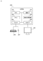
- FIG. 1 is an example of the overall configuration of the information processing system according to the first embodiment.
- the information system according to the first embodiment includes a client terminal 101, a request reception server 103 connected to the client terminal 101 via the network 102, and a data management server 104 connected to the request reception server 103 via the network 105, An application management server 110, a cluster management server 120, and a plurality of processing servers 130 are included.
- the client terminal 101 and other servers (request reception server 103, data management server 104, application management server 110, cluster management server 120, and processing server 130) are connected to different networks (102, 105).
- the information processing system may be configured such that the client terminal 101 and other servers are connected to the same network.
- the client terminal 101 is a terminal used by an application user.
- the application user creates input data to be processed by an application program (hereinafter abbreviated as “application”), and the application receives the application on the request reception server 103. Is used to transmit the processing request together with the input data.
- the client terminal 101 is, for example, a personal computer or server in a company or factory.
- the client terminal 101 may be a communication device having a communication function such as a smartphone or a tablet terminal.
- the network 102 is a wireless network or a wired network provided by a communication carrier or the like.
- the network 102 may include a network owned by an individual company or the like as a part of the network 102, or may be a network that allows a plurality of types of protocols to pass.
- the request reception server 103 receives a processing request such as an application execution request from the client terminal 101, and makes a processing request to the data management server 104, the application management server 110, the cluster management server 120, and the processing server 130 based on the received processing request.
- the server executes processing for returning the processing result to the client terminal 101.
- the data management server 104 is a server that stores data (input data) to be processed when an application is executed.
- the data management server 104 is a shared file server.
- the input data is stored as a record, a structure database server, json
- the server stores data such as an unstructured database such as a key-value store.
- the application management server 110 is a server that manages information on an application executed on the processing server 130 and calculates an estimated value of the execution processing time of the application by setting input data and computer resources.
- the application management server 110 includes an application management storage unit 111 that manages application information, and an application execution time calculation unit 112 that calculates an application execution time in advance based on input data and a computer resource amount. Details will be described with reference to FIGS.
- the cluster management server 120 is a server that manages the usage state of each processing server 130 and dynamically creates / destroys a cluster.
- the node-cluster management information storage unit 121, the cluster generation unit 122, and the cluster discard unit 123 Have.
- a set of computer resources (or a set of processing servers 130 having this computer resource) used when executing one application is called a “cluster”. Details will be described with reference to FIGS. 5, 7, and 8.
- the processing server 130 is a server for executing an application managed by the application management server 110, and includes an application management unit 131 that stores an execution code of the application, and a parallel processing management unit 132 that realizes parallel processing of the application. Have.
- a plurality of applications may be registered in the application management unit 131. When a plurality of applications are registered, a cluster is generated for each application processing request. Therefore, the processing server 130 belongs to a plurality of clusters, and application processing is performed from the processing server 130 in each cluster. Will be allocated. Details will be described with reference to FIG.
- these servers do not necessarily have to be different computers, and the functional units possessed by some of the servers described above may be implemented on a single computer.
- a single computer referred to as a “management server”.
- the functional units included in the request reception server 103, the data management server 104, the application management server 110, and the cluster management server 120 described above may be provided on the management server.
- one (or a plurality) of processing servers may be used as the management server.
- software for providing a so-called virtual computer is executed on one or a plurality of computers provided in the information processing system.
- a virtual machine that serves as a request receiving server a virtual machine that serves as a data management server
- a virtual machine that serves as an application management server a virtual machine that serves as a cluster management server
- the information processing system It may be configured.
- FIG. 2 is a diagram illustrating a physical configuration of the request reception server 103, the data management server 104, the application management server 110, the cluster management server 120, the processing server 130, and the client terminal 101 illustrated in FIG.
- a computer 200 having a processor (CPU) 201, a memory 202, an auxiliary storage device 203, and a communication interface (communication I / F) 204 is used for these servers (or client terminals).
- this computer may be a general-purpose computer such as a personal computer (PC).
- PC personal computer
- the processor 201 executes a program stored in the memory 202.
- the number of processors 201 is not necessarily one.
- the computer 200 may have a plurality of processors 201.
- the processor 201 may be a so-called multi-core processor having a plurality of processor cores.
- the memory 202 includes a ROM that is a nonvolatile storage element and a RAM that is a volatile storage element.
- the ROM stores an immutable program (for example, BIOS).
- BIOS basic BIOS
- the RAM is a high-speed and volatile storage element such as DRAM (Dynamic Random Access Memory), and temporarily stores a program executed by the processor 201 and data used when the program is executed.
- the auxiliary storage device 203 is a large-capacity non-volatile storage device such as a magnetic storage device (HDD) or a flash memory (SSD), and stores a program executed by the processor 201 and data used when the program is executed. To do. That is, the program is read from the auxiliary storage device 203, loaded into the memory 202, and executed by the processor 201.
- HDD magnetic storage device
- SSD flash memory
- the communication interface 204 is a network interface device that controls communication with other devices according to a predetermined protocol.
- the computer 200 may also include an input interface (input I / F) 205 and an output interface (output I / F) 208.
- the input interface 205 is an interface that is connected to a keyboard 206, a mouse 207, and the like and receives input from an operator.
- the output interface 208 is an interface to which a display device 209, a printer, or the like is connected, and the execution result of the program is output in a form that can be visually recognized by the operator.
- each functional unit of the application management server 110, the cluster management server 120, and the processing server 130 is implemented by software (program).
- a program for causing the application management server 110 to function as the application management storage unit 111 and the application execution time calculation unit 112 is loaded on the memory 202 of the application management server 110 (computer 200), and the processor 201. It is executed by.
- the application management server 110 operates as a device having the application management storage unit 111 and the application execution time calculation unit 112.
- the processor 201 of the computer 200 executes a program for realizing each functional unit described above.
- the cluster management server 120 and the processing server 130 operate as devices having the above-described functional units.
- the description will be made with functional units such as the application execution time calculation unit 112 and the cluster generation unit 122 as the subject. In practice, this means that the processor 201 of the computer 200 having a functional unit performs processing.
- the program executed by the processor 201 is provided to the computer 200 via a computer-readable storage medium or network, and is stored in the auxiliary storage device 203 which is a non-temporary storage medium.
- the computer-readable storage medium is a non-transitory computer-readable medium, such as a non-volatile removable medium such as a CD-ROM or flash memory.
- the computer 200 preferably has an interface for reading data from a removable medium.
- some or all of the functional units may be implemented using hardware such as FPGA or ASIC.
- FIG. 3 is a diagram outlining the mechanism when an application is executed on the processing server 130.
- the processing server 130 manages the application management unit 131 in which the application is arranged and the processing server 130 in the same cluster, and manages the parallel execution of the application while allocating the processing to each processing server 130. And a parallel processing management unit 132.
- the application management unit 131 is a functional unit that stores application programs, and holds application programs using the storage areas of the memory 202 and the auxiliary storage device 203.
- the parallel processing management unit 132 provides various functions necessary for executing applications in parallel. Prior to the description of the parallel processing management unit 132, how the application is executed in parallel on the processing server 130 will be outlined.
- an example in which an application is a program for analyzing data will be described as an example.
- the application includes program code (execution code) for executing one or more processes.
- Reference numeral 410 in FIG. 4 indicates a configuration example of the application (App A).
- App A includes a plurality of processes Aa, Ab, and Ac, and when App A is executed on the process server, the processes are executed in the order of processes Aa, Ab, and Ac.
- the process Aa is a process for normalizing input data
- the process Ab is a process for analyzing normalized data
- the process Ac is a statistical process for data analyzed in the process Ab.
- Some processes may be processed in parallel by a plurality of processing servers 130 (or a plurality of processors 201).
- a plurality of processing servers 130 or a plurality of processors 201.
- the processes Aa and Ab are processes that can be executed in parallel will be described.
- An application executes code for causing the processor 201 to execute each of these processes (Aa, Ab, Ac), and an execution code for causing the processor 201 to execute (distribute) each process server 130 to execute (distribute) each process.
- the former execution code is called an “execution unit” (312 in FIG. 3)
- the latter execution code is called a “distribution unit” (311 in FIG. 3).
- the information transmitted by the distribution unit 311 to request each processing server 130 for processing of the execution unit is referred to as a “message”.
- a plurality of processes (Aa, Ab, Ac) are executed as in App A shown in FIG. 3 or FIG.
- the execution unit 312 executes an execution code and a process Ab.
- An execution code and an execution code for performing processing Ac are included.
- the execution codes that perform the processes Aa, Ab, and Ac are referred to as “code Aa”, “code Ab”, and “code Ac”, respectively.
- the parallel processing management unit 132 of the processing server 130 manages parallel execution of applications that are separately designed and defined in the form of a distribution unit 311 and an execution unit 312.
- the parallel processing management unit 132 receives an application execution request from the outside such as the request reception server 103 and starts the execution of the application distribution unit 311 and a message generated by the distribution unit 311.
- the message distribution unit 322 transmitted to the processing server (execution) 130, the message received from the processing server (distribution) 130 are analyzed, and the execution code (code Aa, Ab, Ac) included in the target execution unit 312 is analyzed.
- the message reception unit 323 to be called executes applications in parallel.
- the parallel processing management unit 132 receives an application deployment or undeployment request from the cluster management server 120 or the like, and arranges and deletes applications in the application management unit 310, and an application management unit. Also provided is a function of a cluster information storage unit 325 that manages cluster information about a cluster to which an application arranged in 310 belongs. The cluster information will be described later.
- the parallel processing management unit 132 performs processing such as transmission / reception of this message and execution of processing by the execution unit based on the received message.
- processing such as transmission / reception of this message and execution of processing by the execution unit based on the received message.
- the flow of processing when App A310 is executed will be outlined with reference to FIG.
- N and M are both integers of 1 or more, where N and M are May be equal.
- the processing server 130 that is responsible for the distribution unit 311 that generates and distributes the message is the processing server (distribution) 130
- the processing server that is responsible for the execution unit 312 that receives the message and executes the processing. 130 is referred to as a processing server (execution) 130.
- the processing server (execution) 130 and the processing server (distribution) 130 may be the same server.
- the distribution unit 311 of the processing server (distribution) 130 first generates N messages Aa, and the intra-cluster via the message distribution unit 322 of the parallel processing management unit 132
- the message Aa is transmitted to each processing server 130.
- the distribution server 311 determines the processing server 130 that is the transmission destination of the message Aa.
- the message receiving unit 323 calls a code for executing the processing Aa in the execution unit 312 corresponding to the message Aa, and executes the processing Aa. After executing the process Aa, the message receiving unit 323 returns the process result to the process server (distribution) 130.
- the distribution unit 311 of the processing server (distribution) 130 When the distribution unit 311 of the processing server (distribution) 130 receives N processing result replies corresponding to the message Aa, it generates M messages Ab as the next processing, and the parallel processing management unit 132 similarly.
- the message Ab is transmitted to the processing server (execution) 130 in the cluster via the message distribution unit 322.
- the allocating unit 311 For each process (Aa, Ab, Ac), the allocating unit 311 transmits a message and receives a result, and when receiving a result corresponding to the message Ac, the application ends. That is, the application can be designed and defined separately for the distribution unit 311 that generates a message to be processed and the execution unit 312 that receives the message, so that the repeated processing part can be processed in parallel.
- the processing server 130 By simply placing an application on the processing server 130 by the parallel processing management unit 132 and transmitting an execution request to one of the processing servers 130 in the cluster, the processing server 130 automatically executes the processing server (translation server). Minute) 130 and processing server (execution) 130, and the processing of the application can be executed in parallel while being distributed to the processing server (execution) 130. The flow of these processes will be described later with reference to the sequence diagrams of FIGS.
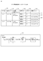
- FIG. 4 is a diagram illustrating an example of a table of the application management storage unit 111 held in the application management server 110.
- the application management storage unit 111 is a functional unit that stores execution code to be arranged as an application, processing flow information for calculating the processing time of the application, and calculation logic information for calculating the execution time for each processing. In order to store such information, the storage area of the memory 202 or the auxiliary storage device 203 is used.
- the application management storage unit 111 may be implemented using a known file system program or a program such as a database management system (DBMS). In this embodiment, an example will be described in which the application management storage unit 111 stores application execution code, processing flow, and calculation logic information in a table formed on the storage area of the memory 202 or the auxiliary storage device 203.
- DBMS database management system
- the table 400 included in the application management storage unit 111 has six columns as shown in FIG. Hereinafter, information stored in each column will be described.
- the application name 401 stores the name of the application.
- the name of an application is a name used to identify an application when an application user requests execution of the application.
- an execution code (file) of the application corresponding to the application name 401 is stored.
- the parallel degree calculation logic 403 stores a file in which logic for calculating the number of repetitions of each process of the application according to the input data amount is described. In this embodiment, the logic for calculating the number of repetitions of each process is called “parallel degree calculation logic”.
- the process flow 404 records the process execution procedure of the application.
- the parallelism 405 stores information indicating whether each process described in the process flow 404 can be executed in parallel.
- the calculation logic 406 stores a file in which calculation logic for calculating one execution time of each process in the processing flow 404 (referred to as “execution time calculation logic”) is described.
- the application stored in the first row of the table of FIG. 4 includes three processes of process Aa, process Ab, and process Ac as described in 410 of FIG. Assume that processing is performed in the order of processing Ab and processing Ac.
- the processing Aa and the processing Ab can be executed in parallel, and the number of repeated executions varies according to the amount of input data given.
- the parallelism calculation logic 403 has a file name of a file in which logic for calculating the number of times of repetition of the processing Aa and the processing Ab is calculated from the amount of input data (“AppA_message.py” in the example of FIG. 4). Is described.
- “process Aa, process Ab, process Ac” are described.
- the row in which “Processing Aa” is stored in the column of the processing flow 404 is “Row 407”
- the row in which “Processing Ab” is stored is “Row 408”
- the row in which “Processing Ac” is stored is “ Call line 409 ".
- the file describing the execution time calculation logic of process Aa is “AppA_calcAa.py”
- the file describing the execution time calculation logic of process Ab is “AppA_calcAb.py”
- the execution time calculation logic of process Ac is described. If the file is “AppA_calcAc.py”, “AppA_calcAa.py” is stored in line 407, “AppA_calcAb.py” is stored in line 408, and “AppA_calcAc.py” is stored in line 409 in the column of calculation logic 406.
- the information stored in the table of the application management storage unit 111 is registered in advance in the application management storage unit 111 by an information processing system administrator or an application user.
- the parallelism calculation logic and the execution time calculation logic are created in advance by an application developer.
- the information processing system may be provided with means for automatically creating the execution time calculation logic. For example, considering the causal relationship between the amount of data and execution time, the function that statistically processes input data and automatically creates calculation logic, and analyzes items that have a causal relationship with execution time in addition to the amount of data
- the information processing system has a function of automatically building a prediction model of calculation logic, and when the application is registered in the application management server 110, the information processing system generates an execution time calculation logic, and an application management storage unit 111 may be registered.
- the executable code and the calculation logic file name (AppA.app, etc.) are described in the columns of the execution code 402, the parallelism calculation logic 403, and the calculation logic 406 for easy understanding.
- the file entity is also stored in these columns.
- the execution code and the calculation logic file entity are stored in the application management storage unit 111 (the storage area of the auxiliary storage device 203 constituting the execution code 402), the parallelism calculation logic 403, and the calculation.
- the logic 406 column may store the path name of each file.
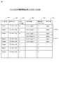
- FIG. 5 is a diagram illustrating an example of a table of the node-cluster management information storage unit 121 held in the cluster management server 120.
- the node-cluster management information storage unit 121 stores various types of information in a table formed on the storage area of the memory 202 or the auxiliary storage device 203 as in the case of the application management storage unit 111 will be described.
- the node-cluster management information storage unit 121 manages information of all processing servers 130 to which applications can be arranged, and among these processing servers 130, the same application is arranged to form a cluster. Information on the processing server 130 is also stored and managed in the table 500.
- Each row (record) of the table 500 included in the node-cluster management information storage unit 121 has six columns as shown in FIG. 5, and each record stores information about the processing server 130 in the information processing system.
- the node name 501 is a column for storing the name of the processing server 130.
- Each processing server 130 has a unique name in the information processing system, and in the present embodiment, the name is referred to as a “node name”.
- the IP address 502 stores the IP address of the processing server 130 specified by the node name 501.
- the number of CPU cores 503 stores the number of processor cores (CPU cores) that the processing server 130 has.
- the cluster name 504 stores the name of the cluster to which the processing server 130 belongs
- the assigned CPU core number 505 stores the number of processor cores assigned to the cluster. Therefore, by calculating the difference between the CPU Core number 503 and the assigned CPU Core number 505, the number of processor cores (referred to as “unused cores”) that are not yet assigned to any cluster is obtained.
- the application name 506 stores the application name of the application arranged in the processing server 130.
- the processing server 130 is described as having a so-called multi-core processor.
- the processor of the processing server 130 is a single core processor
- the CPU Core number 503 and the assigned CPU Core number 505 include a processor.
- the number of processors is stored instead of the number of cores.
- cluster information information included in the set of records having the same cluster name 504, particularly information in the columns 504 to 506 of these records, This is called “cluster information”.
- columns 504 to 506 in the rows 510-1 and 510-2 are the cluster information of the cluster “User1-AppB-1” and the cluster information of the cluster “User2-AppA-5”, respectively.
- the cluster information it is possible to know the number of processing servers 130 and CPU Cores belonging to the cluster.
- the processing server 130 to be assigned to the cluster is selected from the table 500.
- the cluster generation unit 122 stores information such as the cluster name and the number of CPU cores to be used in the columns 504 to 506 of the record corresponding to the selected processing server 130.
- a process in which the cluster generation unit 122 stores information such as a cluster name in the columns 504 to 506 is referred to as a “create cluster information” process.
- creating cluster information it means that computer resources used to execute applications are substantially reserved (reserved).
- the created cluster information is also arranged in the cluster information storage unit 325 of the processing server 130.
- the cluster discarding unit 123 deletes information such as the cluster name from the columns 504 to 506. This process is called a “deletion of cluster information” process.
- the cluster information By deleting the cluster information, the computer resources reserved for executing the application are substantially released, and the released computer resources can be used for other purposes.
- a computer resource on the cloud (not shown) is used as the processing server 130, that is, when a computer resource on the cloud is reserved and used for each cluster generation request, the node is stored each time the computer resource is reserved. -When a record is added to the table of the cluster management information storage unit 121 and the execution of the application is completed and the cluster is deleted, the record is deleted.
- the processing server 130 holds a plurality of CPU Cores and the degree of parallelism of the application is less than the number of CPU Cores of the processing server 130, a plurality of applications may be arranged on one processing server 130. possible. In that case, the processing server 130 belongs to a plurality of clusters.
- the cluster generation unit 122 (described later) of the cluster management server 120 sets the processing server 130 having an unused core as 1 or Select multiple. At that time, the cluster generation unit 122 selects the processing server 130 so that the number of unused cores included in the selected processing server 130 is four (or more).
- the processing servers 130 of Node 1 to Node 8 exist and the CPU Core of Node 1 to Node 5 has already been assigned to some application, it is not used.
- Node 5 and Node 6 may be selected as the processing server 130 having two or more cores.
- the cluster generation unit 122 may secure a computer resource (CPU Core) by adding 2 to the allocation CPU Core 505 of Node 5 and Node 6.
- one or more processing servers 130 may be selected in consideration of the amount of memory and the processing performance of the CPU.
- FIG. 6 is an example of an operation flow of the application execution time calculation unit 112 of the application management server 110.
- the application execution time calculation unit 112 receives an application execution time calculation request specifying an application name, input data, and parallelism as arguments from a request issuer (step 601).
- the request issuer of the application execution time calculation request is the request reception server 103.
- the degree of parallelism may be specified for each process constituting the application. For example, if the application is composed of processes Aa, Ab, and Ac as shown by 410 in FIG. 4 and the processes Aa and Ab are processes that can be executed in parallel, the request issuing source is the parallel degree of the process Aa and the parallel of the process Ab.
- An application execution time calculation request specifying the degree as an argument may be issued to the application execution time calculation unit 112.
- n be the degree of parallelism.
- the application execution time calculation unit 112 acquires the parallelism calculation logic 403 corresponding to the application name and the calculation logic 406 corresponding to each process in the processing flow 404 from the application management storage unit 111 (step 602). Then, the application execution time calculation unit 112 calculates the number of repetitions of each process of the application from the input data amount using the parallel degree calculation logic 403 (step 603), and then uses the calculation logic 406 of each process. The execution time when each process executes the process corresponding to the input data once is calculated (step 604).
- the application execution time calculation unit 112 uses the number of repetitions of each process obtained in step 603 and the execution time of each process obtained in step 604 to execute the application execution time (perform parallel processing). (Execution time when there is no) (step 605), and when a group of processes that can be executed in parallel is executed in parallel, the number of repetitions of each process, the execution time of each process, and the total execution time of the application are calculated, The execution result is returned to the request issuer (step 606).
- the number of repetitions and the execution time are the number of repetitions of each process obtained in step 603 and the execution time of each process obtained in step 604, respectively. determined by dividing by n).
- the application execution time calculation unit 112 executes the flow described above to instantaneously calculate the application execution time from the input data and parallelism, and presents information on the calculation time to the application user. As a result, the application user can determine the parallelism with respect to the allowable execution time by trial and error.
- FIG. 7 is an example of an operation flow of the cluster generation unit 122 of the cluster management server 120.
- the cluster generation unit 122 receives a cluster generation request issued from the request issuer (step 701).
- the request issuing source of the cluster generation request is the request receiving server 103.
- the cluster generation request includes the application name and the degree of parallelism as arguments.
- the cluster generation unit 122 looks at the node-cluster management information storage unit 121 and generates a cluster name having a name that has not yet been recorded in the node-cluster management information storage unit 121, so that A unique name is assigned (step 702).
- the cluster generation unit 122 refers to the node-cluster management information storage unit 121 to select one or a plurality of processing servers 130 having processor cores that are not yet assigned to any cluster (step 703).
- Cluster information is created in the cluster management information storage unit 121 (step 704). Since the selection method of the processing server 130 in step 703 has been described with reference to FIG. 5, description thereof is omitted here.
- the cluster generation unit 122 acquires the execution code 402 of the application corresponding to the application name from the application management server 110 in order to place the application on the selected processing server 130, and requests each processing server to place the application. (Steps 705 and 706). The processing performed by the processing server 130 for which application placement has been requested will be described later.
- the cluster generation unit 122 selects the processing server 130 to be the processing server (distribution) 130 from the processing servers 130 in which the execution code 402 of the application is arranged (Step 707), and the cluster name and the processing server ( An access URL (Uniform Resource Locator) to the (distribution) 130 is returned to the request issuer (step 708).
- the cluster name and the processing server An access URL (Uniform Resource Locator) to the (distribution) 130 is returned to the request issuer (step 708).
- FIG. 8 is an example of an operation flow of the cluster discard unit 123 of the cluster management server 120.
- the cluster discard unit 123 accepts a cluster discard request in which the cluster name is specified as an argument from the request issuer (step 801). Again, the request issuer is the request reception server 103.
- the cluster discarding unit 123 acquires information on the processing servers 130 in the cluster from the node-cluster management information storage unit 121 (Step 802), and causes each processing server 130 to delete the application (Step 803).
- the cluster discarding unit 123 deletes the cluster information in the node-cluster management information storage unit 121 (step 804), and returns a completion notification to the request issuer (step 805).
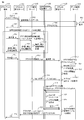
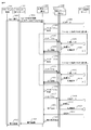
- FIG. 9 is a sequence diagram showing the flow of processing performed in each server in the information processing system when the application user requests execution of the application using the information processing system according to the present embodiment.
- FIG. 9 describes the flow of processing from when the client terminal 101 issues a request to the request reception server 103 until a cluster for executing the application is generated.
- the client terminal 101 transmits an application registration request to the request reception server 103 (901).
- This application registration request includes an application name (for example, “AppA”) and input data.
- the request reception server 103 first registers input data in the data management server 104 (902, 903).
- the data management server 104 receives the input data
- the data management server 104 returns an access URL (904) as an access method to the input data to the request reception server 103.
- the request reception server 103 Upon receiving the access URL (904), the request reception server 103 returns OK (905) to the client terminal 101.
- the request reception server 103 holds the URL to the input data and the application name in association with each other.
- the application user designates the degree of parallelism (906) using the client terminal 101.
- the request reception server 103 causes the application execution time calculation unit 112 of the application management server 110 to calculate the number of repetitions and the execution time of each process (907, 908, 909), and the result is the client terminal 101. (910).
- the processing performed by the application management server 110 in steps 907, 908, and 909 corresponds to the processing in FIG.
- the application user repeats the processing from 906 to 910 while changing the degree of parallelism until the application execution time calculated by the application execution time calculation unit 112 falls within the time desired by the application user. For example, when the execution time of an application calculated when a certain degree of parallelism (assumed to be n) is specified is longer than the execution time desired by the application user, the application user has a degree of parallelism higher than n ( For example, (n + 1) or the like may be designated and the application execution time calculation unit 112 may calculate the application execution time.
- the application user has a degree of parallelism lower than the initially specified degree of parallelism (n) (for example, (n-1), etc. ) May be designated to cause the application execution time calculation unit 112 to calculate the application execution time.
- n initially specified degree of parallelism
- the application user determines the degree of parallelism when the application is actually executed by repeating the processing of 906 to 910 described above (hereinafter, the degree of parallelism determined by the application user is referred to as “runtime parallelism”.
- the degree of parallelism designated by the application user in 906 in FIG. 9 is distinguished).
- the application user transmits a cluster generation request specifying the runtime parallelism and the application name from the client terminal 101 to the cluster management server 120 via the request reception server 103 (911, 912). ).
- a specific method for the application user to specify the degree of parallelism in this processing will be described later with reference to FIG. 12 (or FIG. 13).
- the cluster management server 120 receives the cluster generation request (912), the cluster generation unit 122 creates a cluster name (913), and secures the computer resource (CPU Core) of the processing server 130 according to the parallelism at the time of execution.
- cluster information is created in the node-cluster management information storage unit 121 (915). Processes 912 to 915 are processes corresponding to steps 701 to 704 in FIG.
- the cluster generation unit 122 acquires the execution code (916) of the application from the application management server 110 (917), and requests each processing server 130 to arrange the application (918).
- Processes 917 to 918 are processes corresponding to steps 705 to 706 in FIG.
- the cluster generation unit 122 requests the processing server 130 to place an application, the execution code of the application and cluster information are transmitted to the processing server 130.
- the processing server 130 requested to arrange the application installs the application (919) and creates cluster information in the cluster information storage unit 325 of the parallel processing management unit 132 (920).
- the cluster management server 120 includes one processing server 130 that becomes the processing server (distribution) 130 among the processing servers 130 belonging to the cluster.
- the access URL to the processing server (distribution) 130 is returned to the request receiving server 103 together with the cluster name (923).
- the request reception server 103 returns OK (924) to the client terminal 101, and the processing is completed.
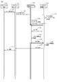
- FIG. 10 is an example of an operation sequence for executing application processing in parallel using the processing server 130 group determined by the processing in FIG. 9 following the processing in FIG. 9.
- the request reception server 103 receives input data for an access URL to the processing server (distribution) 130.
- An execution request is transmitted together with the access URL (1002).
- the request reception server 103 returns OK to the client terminal 101 (924), and then the application user issues an application execution request (1001).
- an execution request is transmitted (1002) to the processing server (distribution) 130.
- the request receiving server 103 sends a reply (924) to the client terminal 101.
- the application execution request may be transmitted (1002) to the processing server (distribution) 130.
- the application distribution unit 311 In the processing server (distribution) 130, the application distribution unit 311 generates the same number of messages Aa as the degree of parallelism (runtime parallelism) specified in 911 (1004), and each message Aa (1005) It is transmitted to the processing server (execution) 130.
- the processing server (distribution) 130 acquires the input data from the data management server 104 (1003).
- the processing server (execution) 130 When the processing server (execution) 130 receives the message Aa, the processing server (execution) 130 acquires target data (1006) necessary for the processing Aa from the input data stored in the data management server 104, and executes the processing Aa of the execution unit 312. Then, the processing result (1008) is written in the data management server 104 and a processing completion notification (1009) is returned to the processing server (distribution) 130.
- the processing server (distribution) 130 When the processing server (distribution) 130 receives completion notifications from all the processing servers (execution) 130 that transmitted the message (1009), it generates the next message (“message Ab” in the example of FIG. 10), Allocate to each processing server (execution) 130. In this way, the processing server (distribution) 130 repeats the process of generating a message, distributing the message to each processing server (execution) 130, and receiving a processing completion notification from each processing server (execution) 130. When the processing server (distribution) 130 receives a processing completion notification for the last message (“message Ac” in the example of FIG.
- the processing server (distribution) 130 acquires the final result from the data management server 104. (1022) An execution result as an application is generated (1023), and the execution result (1024, 1025) is returned to the client terminal 101 via the request reception server 103.
- FIG. 11 shows an example of processing performed after FIG. 10, that is, processing from the end of application execution until the cluster is discarded.
- the request reception server 103 receives an application execution completion notification (1101) from the client terminal 101, the request reception server 103 transmits a cluster destruction request (1102) to the cluster management server 120, and a cluster destruction unit. 123 accepts this cluster discard request.
- This process corresponds to step 801 in FIG.
- the cluster discard request includes the cluster name to be discarded.
- the cluster destruction unit 123 refers to the node-cluster management information storage unit 121 to identify the processing server 130 and the application name in the cluster (1103). This process corresponds to step 802. Then, the cluster discard unit 123 transmits an application discard request (1104) to each identified processing server 130 (a process corresponding to step 803).
- each processing server 130 Upon receiving the application discard request, each processing server 130 uninstalls the application (1105), discards the cluster information recorded in the cluster information storage unit 325 (1106), and then sends a completion notification to the cluster management server 120. Return it.
- the cluster discard unit 123 receives the completion notification (1107) from each processing server 130, the cluster information in the node-cluster management information storage unit 121 is deleted (1108), and the completion notification is sent to the client terminal 101 via the request reception server 103. (1109, 1101) is returned.
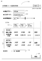
- FIG. 12 is an example of a computer resource amount setting screen image for the application user to determine the computer resource amount for each execution request.
- the request reception server 103 creates this setting screen 1200 and provides it to the client terminal 101 (displayed on the display device 209 of the client terminal 101).
- a computer other than the request reception server 103 may create the setting screen 1200.
- 1201 is an application name input box
- 1202 is a data name input box
- 1206 is a parallel degree setting column.
- the request reception server 103 performs each process in the processing flow when parallel processing is not performed first based on the application name input by the application user in the application name input box 1201 and the data name input box 1202 and the registered input data.
- the application execution time calculation unit 112 is caused to calculate the number of repetitions, the expected value of the processing time of each process, and the total execution time of each process (the process up to step 605 in FIG. 6 is performed).
- the request reception server 103 creates a screen for displaying the calculated information (1204) in association with the application processing flow (1203), and causes the display device 209 of the client terminal 101 to output this screen.
- the application management server 110 When the application user inputs the parallel degree in the parallel degree setting field 1206 based on the displayed information, the input parallel degree is transmitted to the application management server 110. As described above with reference to FIGS. 6 and 9, the application management server 110 performs the parallel processing using the passed degree of parallelism or the like, the number of repetitions of each process, the expected value of the processing time, and the application The total execution time is obtained, and a screen displaying the result in the display area (1205) is created and displayed on the client terminal 101. Therefore, the application user gradually increases the parallelism input in the parallelism setting field 1206 until the total execution time of the application displayed in the display area (1205) is within the execution time desired by the application user. It is good to repeat.
- the computer resource amount setting screen 1200 is provided with a cost display field (1208), and the request reception server 103 (or application management server 110) determines the parallelism of the application and the execution time of the application (execution time when the application is executed in parallel). ) (Information processing system usage fee) may be calculated, and the calculated cost information may be provided to the application user.
- the application user can determine the parallelism (runtime parallelism) that satisfies the current execution request while observing the balance between the execution time for completing the application and the cost required according to the parallelism.
- the request reception server 103 receives from the client terminal 101 the application name and parallelism (runtime parallelism) set by the application user in the application name input box 1201 and the parallelism setting field 1206. Then, the request reception server 103 transmits a cluster generation request specifying the execution parallelism and the application name to the cluster management server 120 (the processing of 911 and 912 in FIG. 9 is performed).
- the request reception server 103 transmits an application execution request to the processing server (distribution) 130 (FIG. 9). 10 1002).
- the information processing system includes the functions described above, thereby generating an execution environment of a parallel computing system that satisfies the execution request for each execution request, and executing the applications in parallel.
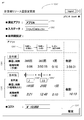
- Example 2 describes an example of an information processing system that can set the degree of parallelism for each process of an application. Since the configuration of the information processing system according to the second embodiment is the same as that described in the first embodiment, description of the configuration is omitted, and only differences from the content described in the first embodiment will be described.
- FIG. 13 shows an example of a computer resource amount setting screen 1200 'according to the second embodiment.
- the setting screen 1200 ′ in FIG. 13 differs from the setting screen 1200 described in FIG. 12 in that the setting screen 1200 ′ in FIG. 13 includes a parallel degree setting column for each process that can be executed in parallel (FIG. 13: 1206). 'And 1206' '), the application user can set the degree of parallelism for each process. Further, when the application management server 110 calculates the execution time of the application, the calculation is performed based on the degree of parallelism set for each process on the setting screen 1200 ′′.
- the parallelism can be set for each process of the application, so that when the processing time for each process is different, the application user By increasing the setting, the effect of shortening the total execution time is great, and it becomes possible to select measures that minimize the cost as much as possible.
- the degree of parallelism for each process for example, by setting the total execution time after parallelization, the degree of parallelism for each process is calculated, and the cost is set. Accordingly, a method for setting the degree of parallelism is also conceivable in which the setting of the degree of parallelism of each process is calculated so that the execution time is shortened accordingly.
- the application user can determine the amount of computer resources desired by the application user from the viewpoint of total execution time, cost, etc. It is possible to provide an execution environment of a parallel computing system in which a user can immediately execute an application in parallel.
- the method of specifying input data from the client terminal 101 when an application execution request is made has been described.
- data is registered in the data management server 104 in advance, At this time, the application user may process the input data by designating the data stored in the data management server 104 as the input data.
- 101 Client terminal, 102: Network, 103: Request reception server, 104: Data management server, 110: Application management server, 120: Cluster management server, 130: Processing server
Abstract
The purpose of the present invention is to provide a parallel computing system which is capable of determining computer resource quantities which are required for each execution request by an application user, and of securing the computer resources for each execution. An information processing system according to an embodiment of the present invention comprises a management server and a plurality of processing servers which each further comprise one or more processors for executing application programs. Upon receiving a concurrency of an application program from a user, the management server secures, from among usable computer resources which the plurality of processing servers comprises, the computer resources which are necessary to execute the application program at the received concurrency, positions the application program upon the processing server which comprises the secured computing resources, and causes the processing server to perform parallel execution of the application program.
Description
本発明は、複数のサーバを含む情報処理システム及びその制御方法に関するものである。
The present invention relates to an information processing system including a plurality of servers and a control method thereof.
近年、人工知能や機械学習などのように、大量のデータを網羅的に繰返し分析して、人が想定し得ない結果を導き出す分析アプリケーションが注目を集めている。このようなアプリケーションは、結果を導き出すまでに長時間掛かるため、繰返し処理部分に並列コンピューティングシステムを適用して、実行時間を短縮することが望まれている。しかし、アプリケーションの分析対象となるデータ量や分析パラメータ(たとえば、データの分割粒度など)により、実行時間が異なるため、アプリケーションを利用する分析者は、希望する実行時間以内に処理を完了するために、どれだけの計算機リソースを準備しておけばよいか決定することが困難である。
In recent years, analysis applications, such as artificial intelligence and machine learning, that exhaustively and repeatedly analyze large amounts of data to derive results that humans cannot expect have attracted attention. Since such an application takes a long time to derive a result, it is desired to reduce the execution time by applying a parallel computing system to the repetitive processing part. However, since the execution time varies depending on the amount of data to be analyzed by the application and the analysis parameters (for example, data division granularity), analysts using the application must complete the process within the desired execution time. It is difficult to determine how many computer resources should be prepared.
このような分野の背景技術として、特許文献1では、クラウドを活用して、アプリケーションに対する処理の需要を予測して、クラウドのリソースを自動で拡張及び縮小するアプリケーション・リソース・マネージャを提供している。
As background art of such a field, Patent Document 1 provides an application resource manager that uses a cloud to predict processing demand for an application and automatically expands and reduces the resources of the cloud. .
特許文献1に記載されたアプリケーション・リソース・マネージャを用いれば、アプリケーションの負荷状況を予測して、指定されたポリシーに基づき迅速に計算機リソースを確保すると共に、イメージを高速配備(プロビジョニング)、もしくは使用されてないイメージをスタッシュして、アプリケーションの処理負荷を動的に変更することができる。これにより、アプリケーション利用者は、事前に計算機リソース量を決定しなくても、ポリシーに基づいた計算機リソースを利用することができる。
By using the application resource manager described in Patent Document 1, the load status of the application is predicted, and computer resources are quickly secured based on a specified policy, and an image is rapidly deployed (provisioned) or used. Unstapled images can be stashed to dynamically change application processing load. Thereby, the application user can use the computer resource based on the policy without determining the computer resource amount in advance.
しかしながら、アプリケーション・リソース・マネージャで想定されているポリシーは、継続的にアプリケーションが実行されているときの負荷変動に対して、一定に保つように計算機リソースを確保する方法であり、アプリケーション利用者が、実行要求毎に利用形態やコスト等を鑑みて、計算機リソース量を決定するようなケースは想定されていない。
However, the policy assumed by the application resource manager is a method for securing computer resources so as to keep constant against load fluctuations when the application is continuously executed. In view of the usage pattern, cost, etc. for each execution request, no case is assumed where the computer resource amount is determined.
たとえば、アプリケーション利用者が、分析パラメータを試行錯誤しながら調整する利用形態を想定した場合、最初は分析粒度を粗く検証するために短実行時間であまり計算機リソースを使わず、すなわち計算機リソースにコストを掛けずに分析を行い、詳細分析をする際に、分析粒度を細かくするように分析パラメータを設定して、実行時間を短縮させるために、コストを掛けて計算機リソースを多めに利用したい、などのニーズが考えられる。このような利用形態の場合、アプリケーション利用者ごとに必要とする計算機リソース量が異なるために、特許文献1に記載の技術のように、ポリシーに基づく計算機リソースの確保を行う方法では、対応が困難である。
For example, when an application user assumes a usage pattern in which analysis parameters are adjusted through trial and error, initially, in order to verify the analysis granularity, less computer resources are used in a short execution time, that is, the computer resources are reduced in cost. If you want to use a lot of computer resources at a high cost in order to shorten the execution time by setting analysis parameters to make the analysis granularity finer when performing analysis without detailed analysis, etc. Needs are considered. In such a usage mode, the amount of computer resources required for each application user differs, so that it is difficult to cope with a method for securing computer resources based on a policy as in the technique described in Patent Document 1. It is.
上記目的を達成するために、本発明の一実施形態に係る情報処理システムは、管理サーバと、アプリケーションプログラムを実行するための1以上のプロセッサを備えた処理サーバを複数有する。管理サーバは、ユーザからアプリケーションプログラムの並列度を受領すると、複数の処理サーバの有する使用可能な計算機リソースの中から、受領した並列度でアプリケーションプログラムを実行するために必要な計算機リソースを確保し、確保された計算機リソースを有する処理サーバに、アプリケーションプログラムを配置し、アプリケーションプログラムを並列実行させる。
In order to achieve the above object, an information processing system according to an embodiment of the present invention includes a plurality of processing servers including a management server and one or more processors for executing application programs. When the management server receives the parallel degree of the application program from the user, the management server secures a computer resource necessary for executing the application program with the received parallel degree from among the usable computer resources of the plurality of processing servers. An application program is arranged on a processing server having a reserved computer resource, and the application program is executed in parallel.
本発明によれば、アプリケーション利用者が、アプリケーションの実行要求毎に必要な計算機リソース量を、アプリケーション利用者の処理要求に合わせて柔軟に決定して、決定した計算機リソース量で迅速に並列コンピューティングシステムを構築することが可能となる。
According to the present invention, an application user flexibly determines the amount of computer resources required for each execution request of an application according to the processing request of the application user, and quickly performs parallel computing with the determined amount of computer resources. It becomes possible to construct a system.
以下、各実施例における実施形態について図面を参照して説明する。なお、以下の実施例に用いる図において、同一の符号を付した部分は同一物を表し、それらの構造および動作は同じである。
Hereinafter, embodiments of each example will be described with reference to the drawings. In the drawings used in the following embodiments, the same reference numerals denote the same components, and the structure and operation thereof are the same.
図1は、実施例1に係る情報処理システムの全体構成の例である。実施例1に係る情報システムは、クライアント端末101と、クライアント端末101とネットワーク102を介して接続されるリクエスト受付サーバ103、そしてネットワーク105を介してリクエスト受付サーバ103と接続されるデータ管理サーバ104、アプリ管理サーバ110、クラスタ管理サーバ120、複数の処理サーバ130を有する。図1ではクライアント端末101とそれ以外のサーバ(リクエスト受付サーバ103、データ管理サーバ104、アプリ管理サーバ110、クラスタ管理サーバ120、処理サーバ130)が異なるネットワーク(102,105)に接続されているが、クライアント端末101とそれ以外のサーバが同一ネットワークに接続されるように、情報処理システムが構成されていてもよい。
FIG. 1 is an example of the overall configuration of the information processing system according to the first embodiment. The information system according to the first embodiment includes a client terminal 101, a request reception server 103 connected to the client terminal 101 via the network 102, and a data management server 104 connected to the request reception server 103 via the network 105, An application management server 110, a cluster management server 120, and a plurality of processing servers 130 are included. In FIG. 1, the client terminal 101 and other servers (request reception server 103, data management server 104, application management server 110, cluster management server 120, and processing server 130) are connected to different networks (102, 105). The information processing system may be configured such that the client terminal 101 and other servers are connected to the same network.
クライアント端末101は、アプリケーション利用者が使用する端末であり、アプリケーション利用者が、アプリケーションプログラム(以下、「アプリケーション」と略記する)に処理させるための入力データを作成して、リクエスト受付サーバ103にアプリケーションの処理要求を入力データとともに送信するために用いられる。クライアント端末101はたとえば、会社や工場内のパーソナルコンピュータやサーバである。あるいはクライアント端末101は、スマートフォンやタブレット端末などの、通信機能を有する通信デバイスであってもよい。
The client terminal 101 is a terminal used by an application user. The application user creates input data to be processed by an application program (hereinafter abbreviated as “application”), and the application receives the application on the request reception server 103. Is used to transmit the processing request together with the input data. The client terminal 101 is, for example, a personal computer or server in a company or factory. Alternatively, the client terminal 101 may be a communication device having a communication function such as a smartphone or a tablet terminal.
ネットワーク102は、通信キャリアなどによって提供される無線ネットワークまたは有線ネットワークである。ネットワーク102は、個別の会社などが所有するネットワークを、ネットワーク102の一部に含んでもよく、複数種類のプロトコルを通過させるネットワークであってもよい。
The network 102 is a wireless network or a wired network provided by a communication carrier or the like. The network 102 may include a network owned by an individual company or the like as a part of the network 102, or may be a network that allows a plurality of types of protocols to pass.
リクエスト受付サーバ103は、クライアント端末101からアプリ実行要求などの処理要求を受け付け、受け付けた処理要求に基づき、データ管理サーバ104、アプリ管理サーバ110、クラスタ管理サーバ120、処理サーバ130に処理依頼を行い、処理結果をクライアント端末101に返信する処理を実行するサーバである。
The request reception server 103 receives a processing request such as an application execution request from the client terminal 101, and makes a processing request to the data management server 104, the application management server 110, the cluster management server 120, and the processing server 130 based on the received processing request. The server executes processing for returning the processing result to the client terminal 101.
データ管理サーバ104は、アプリケーションの実行時に処理対象となるデータ(入力データ)を格納するサーバであり、入力データがファイルの場合は共有ファイルサーバ、レコードとして格納しておく場合は構造データベースサーバ、jsonなどの形式で格納しておく場合はキーバリューストアなどの非構造データベースなどのデータを格納するサーバである。
The data management server 104 is a server that stores data (input data) to be processed when an application is executed. When the input data is a file, the data management server 104 is a shared file server. When the input data is stored as a record, a structure database server, json For example, the server stores data such as an unstructured database such as a key-value store.
アプリ管理サーバ110は、処理サーバ130で実行されるアプリケーションの情報を管理するとともに、入力データや計算機リソースを設定することでアプリケーションの実行処理時間の見積もり値を計算するサーバである。アプリ管理サーバ110は、アプリケーションの情報を管理するアプリ管理記憶部111と、入力データと計算機リソース量に基づきアプリケーションの実行時間を事前に計算するアプリ実行時間計算部112と、を有する。詳細は、図4および図6で説明する。
The application management server 110 is a server that manages information on an application executed on the processing server 130 and calculates an estimated value of the execution processing time of the application by setting input data and computer resources. The application management server 110 includes an application management storage unit 111 that manages application information, and an application execution time calculation unit 112 that calculates an application execution time in advance based on input data and a computer resource amount. Details will be described with reference to FIGS.
クラスタ管理サーバ120は、各処理サーバ130の利用状態を管理して、クラスタの生成/破棄を動的に行うサーバであり、ノード-クラスタ管理情報記憶部121とクラスタ生成部122、クラスタ破棄部123、を有する。本実施例では、1つのアプリケーションを実行する際に使用される計算機リソースの集合(あるいはこの計算機リソースを有する処理サーバ130の集合)を「クラスタ」と呼ぶ。詳細は、図5および図7、図8で説明する。
The cluster management server 120 is a server that manages the usage state of each processing server 130 and dynamically creates / destroys a cluster. The node-cluster management information storage unit 121, the cluster generation unit 122, and the cluster discard unit 123 Have. In this embodiment, a set of computer resources (or a set of processing servers 130 having this computer resource) used when executing one application is called a “cluster”. Details will be described with reference to FIGS. 5, 7, and 8.
処理サーバ130は、アプリ管理サーバ110が管理しているアプリケーションを実行するためのサーバであり、アプリケーションの実行コードを記憶するアプリケーション管理部131と、アプリケーションの並列処理を実現する並列処理管理部132と、を有する。アプリケーション管理部131には、複数のアプリケーションが登録されてもよい。複数のアプリケーションが登録されている場合、クラスタはアプリケーションの処理要求ごとに生成されるため、処理サーバ130は複数のクラスタに属していることとなり、それぞれのクラスタ内の処理サーバ130からアプリケーションの処理を割り振られることとなる。詳細は図3で説明する。
The processing server 130 is a server for executing an application managed by the application management server 110, and includes an application management unit 131 that stores an execution code of the application, and a parallel processing management unit 132 that realizes parallel processing of the application. Have. A plurality of applications may be registered in the application management unit 131. When a plurality of applications are registered, a cluster is generated for each application processing request. Therefore, the processing server 130 belongs to a plurality of clusters, and application processing is performed from the processing server 130 in each cluster. Will be allocated. Details will be described with reference to FIG.
本実施例では、これらのサーバがそれぞれ物理的に異なる計算機である例を説明する。ただし必ずしもこれらのサーバが、異なる計算機である必要はなく、上で述べたいくつかのサーバが有する機能部が、単一の計算機上に実装されていてもよい。たとえば情報処理システム内に、上で述べたリクエスト受付サーバ103、データ管理サーバ104、アプリ管理サーバ110、クラスタ管理サーバ120に代えて、1台の計算機(仮に「管理サーバ」と呼ぶ)を設け、上で述べたリクエスト受付サーバ103、データ管理サーバ104、アプリ管理サーバ110、クラスタ管理サーバ120が有する機能部を、その管理サーバ上に設けてもよい。あるいは、処理サーバの1つ(または複数)が、管理サーバとして用いられてもよい。
In this embodiment, an example in which these servers are physically different computers will be described. However, these servers do not necessarily have to be different computers, and the functional units possessed by some of the servers described above may be implemented on a single computer. For example, in the information processing system, instead of the request reception server 103, the data management server 104, the application management server 110, and the cluster management server 120 described above, a single computer (referred to as a “management server”) is provided. The functional units included in the request reception server 103, the data management server 104, the application management server 110, and the cluster management server 120 described above may be provided on the management server. Alternatively, one (or a plurality) of processing servers may be used as the management server.
さらに別の実施形態として、情報処理システム内に設けられた1台または複数台の計算機上で、いわゆる仮想計算機を提供するためのソフトウェア(一般的にハイパーバイザと呼ばれる)を実行させ、計算機上に、リクエスト受付サーバの役割を果たす仮想計算機、データ管理サーバの役割を果たす仮想計算機、アプリ管理サーバの役割を果たす仮想計算機、クラスタ管理サーバの役割を果たす仮想計算機を定義することで、情報処理システムが構成されてもよい。
As yet another embodiment, software (generally called a hypervisor) for providing a so-called virtual computer is executed on one or a plurality of computers provided in the information processing system. By defining a virtual machine that serves as a request receiving server, a virtual machine that serves as a data management server, a virtual machine that serves as an application management server, and a virtual machine that serves as a cluster management server, the information processing system It may be configured.
図2は、図1で示したリクエスト受付サーバ103、データ管理サーバ104、アプリ管理サーバ110、クラスタ管理サーバ120、処理サーバ130、クライアント端末101の物理的な構成を示す図である。本実施例ではこれらのサーバ(またはクライアント端末)には、プロセッサ(CPU)201、メモリ202、補助記憶装置203及び通信インターフェース(通信I/F)204を有する計算機200が用いられる。この計算機は一例として、パーソナルコンピュータ(PC)等の汎用的な計算機でよい。
FIG. 2 is a diagram illustrating a physical configuration of the request reception server 103, the data management server 104, the application management server 110, the cluster management server 120, the processing server 130, and the client terminal 101 illustrated in FIG. In this embodiment, a computer 200 having a processor (CPU) 201, a memory 202, an auxiliary storage device 203, and a communication interface (communication I / F) 204 is used for these servers (or client terminals). As an example, this computer may be a general-purpose computer such as a personal computer (PC).
プロセッサ201は、メモリ202に格納されたプログラムを実行する。プロセッサ201の数は1とは限らない。計算機200は複数のプロセッサ201を有していてもよい。またプロセッサ201は複数のプロセッサコアを有する、いわゆるマルチコアプロセッサであってもよい。メモリ202は、不揮発性の記憶素子であるROM及び揮発性の記憶素子であるRAMを含む。ROMは、不変のプログラム(例えば、BIOS)などを格納する。RAMは、DRAM(Dynamic Random Access Memory)のような高速かつ揮発性の記憶素子であり、プロセッサ201が実行するプログラム及びプログラムの実行時に使用されるデータを一時的に格納する。
The processor 201 executes a program stored in the memory 202. The number of processors 201 is not necessarily one. The computer 200 may have a plurality of processors 201. The processor 201 may be a so-called multi-core processor having a plurality of processor cores. The memory 202 includes a ROM that is a nonvolatile storage element and a RAM that is a volatile storage element. The ROM stores an immutable program (for example, BIOS). The RAM is a high-speed and volatile storage element such as DRAM (Dynamic Random Access Memory), and temporarily stores a program executed by the processor 201 and data used when the program is executed.
補助記憶装置203は、例えば、磁気記憶装置(HDD)、フラッシュメモリ(SSD)等の大容量かつ不揮発性の記憶装置であり、プロセッサ201が実行するプログラム及びプログラムの実行時に使用されるデータを格納する。すなわち、プログラムは、補助記憶装置203から読み出されて、メモリ202にロードされて、プロセッサ201によって実行される。
The auxiliary storage device 203 is a large-capacity non-volatile storage device such as a magnetic storage device (HDD) or a flash memory (SSD), and stores a program executed by the processor 201 and data used when the program is executed. To do. That is, the program is read from the auxiliary storage device 203, loaded into the memory 202, and executed by the processor 201.
通信インターフェース204は、所定のプロトコルに従って、他の装置との通信を制御するネットワークインターフェース装置である。
The communication interface 204 is a network interface device that controls communication with other devices according to a predetermined protocol.
計算機200はまた、入力インターフェース(入力I/F)205及び出力インターフェース(出力I/F)208を有してもよい。入力インターフェース205は、キーボード206やマウス207などが接続され、オペレータからの入力を受けるインターフェースである。出力インターフェース208は、ディスプレイ装置209やプリンタなどが接続され、プログラムの実行結果をオペレータが視認可能な形式で出力するインターフェースである。
The computer 200 may also include an input interface (input I / F) 205 and an output interface (output I / F) 208. The input interface 205 is an interface that is connected to a keyboard 206, a mouse 207, and the like and receives input from an operator. The output interface 208 is an interface to which a display device 209, a printer, or the like is connected, and the execution result of the program is output in a form that can be visually recognized by the operator.
なお、本実施例では、アプリ管理サーバ110、クラスタ管理サーバ120、処理サーバ130の有する各機能部は、ソフトウェア(プログラム)によって実装されるものとする。たとえばアプリ管理サーバ110では、アプリ管理サーバ110をアプリ管理記憶部111とアプリ実行時間計算部112として機能させるためのプログラムが、アプリ管理サーバ110(計算機200)のメモリ202上にロードされ、プロセッサ201により実行される。これによりアプリ管理サーバ110は、アプリ管理記憶部111とアプリ実行時間計算部112を有する装置として動作する。
In this embodiment, each functional unit of the application management server 110, the cluster management server 120, and the processing server 130 is implemented by software (program). For example, in the application management server 110, a program for causing the application management server 110 to function as the application management storage unit 111 and the application execution time calculation unit 112 is loaded on the memory 202 of the application management server 110 (computer 200), and the processor 201. It is executed by. Thereby, the application management server 110 operates as a device having the application management storage unit 111 and the application execution time calculation unit 112.
クラスタ管理サーバ120や処理サーバ130でも同様に、計算機200(クラスタ管理サーバ120や処理サーバ130)のプロセッサ201で、上で述べた各機能部を実現するためのプログラムが実行される。これによってクラスタ管理サーバ120や処理サーバ130は、上で述べた各機能部を有する装置として動作する。以下では、アプリ管理サーバ110やクラスタ管理サーバ120、あるいは処理サーバ130等で実行される処理を説明する際に、アプリ実行時間計算部112やクラスタ生成部122等の機能部を主語とした説明を行うことがあるが、それは実際には、機能部を有する計算機200のプロセッサ201が処理を行うことを意味する。
Similarly, on the cluster management server 120 and the processing server 130, the processor 201 of the computer 200 (the cluster management server 120 and the processing server 130) executes a program for realizing each functional unit described above. As a result, the cluster management server 120 and the processing server 130 operate as devices having the above-described functional units. In the following, when the processing executed by the application management server 110, the cluster management server 120, the processing server 130, or the like is described, the description will be made with functional units such as the application execution time calculation unit 112 and the cluster generation unit 122 as the subject. In practice, this means that the processor 201 of the computer 200 having a functional unit performs processing.
また、プロセッサ201が実行するプログラムは、計算機が読み取り可能な記憶メディア又はネットワークを介して計算機200に提供され、非一時的記憶媒体である補助記憶装置203に格納される。計算機が読み取り可能な記憶メディアとは、非一時的なコンピュータ可読媒体で、たとえばCD-ROMやフラッシュメモリなどの、不揮発性のリムーバブルメディアである。このため計算機200は、リムーバブルメディアからデータを読み込むインターフェースを有するとよい。
Further, the program executed by the processor 201 is provided to the computer 200 via a computer-readable storage medium or network, and is stored in the auxiliary storage device 203 which is a non-temporary storage medium. The computer-readable storage medium is a non-transitory computer-readable medium, such as a non-volatile removable medium such as a CD-ROM or flash memory. For this reason, the computer 200 preferably has an interface for reading data from a removable medium.
また、別の実施形態として、各機能部の一部またはすべては、FPGAやASICなどのハードウェアを用いて実装されていてもよい。
As another embodiment, some or all of the functional units may be implemented using hardware such as FPGA or ASIC.
図3は、処理サーバ130でアプリケーションが実行される時の仕組みを概説する図である。
FIG. 3 is a diagram outlining the mechanism when an application is executed on the processing server 130.
処理サーバ130は先に述べたとおり、アプリケーションが配置されるアプリケーション管理部131と、同一クラスタ内の処理サーバ130を管理して、処理を各処理サーバ130に割り振りながらアプリケーションを並列実行することを管理する並列処理管理部132と、を有する。
As described above, the processing server 130 manages the application management unit 131 in which the application is arranged and the processing server 130 in the same cluster, and manages the parallel execution of the application while allocating the processing to each processing server 130. And a parallel processing management unit 132.
アプリケーション管理部131はアプリケーションプログラムを格納する機能部で、メモリ202や補助記憶装置203の記憶領域を用いてアプリケーションプログラムを保持する。
The application management unit 131 is a functional unit that stores application programs, and holds application programs using the storage areas of the memory 202 and the auxiliary storage device 203.
並列処理管理部132は、アプリケーションを並列実行させるために必要な、各種機能を提供する。並列処理管理部132の説明の前に、処理サーバ130でアプリケーションがどのようにして並列実行されるか、概説する。
The parallel processing management unit 132 provides various functions necessary for executing applications in parallel. Prior to the description of the parallel processing management unit 132, how the application is executed in parallel on the processing server 130 will be outlined.
本実施例では一例として、アプリケーションがデータの分析を行うためのプログラムである例を説明する。アプリケーションは、1以上の処理を実行するためのプログラムコード(実行コード)を含む。図4の410は、アプリケーション(App A)の構成例を示している。図4の410に示されているように、App Aは複数の処理Aa,Ab,Acを含んでおり、App Aが処理サーバで実行される時、処理Aa,Ab,Acの順に実行される。ここで、たとえば処理Aaは入力データの正規化を行う処理、処理Abは正規化されたデータの分析を行う処理、そして処理Acは処理Abにて分析されたデータの統計処理である。
In this embodiment, an example in which an application is a program for analyzing data will be described as an example. The application includes program code (execution code) for executing one or more processes. Reference numeral 410 in FIG. 4 indicates a configuration example of the application (App A). As indicated by 410 in FIG. 4, App A includes a plurality of processes Aa, Ab, and Ac, and when App A is executed on the process server, the processes are executed in the order of processes Aa, Ab, and Ac. . Here, for example, the process Aa is a process for normalizing input data, the process Ab is a process for analyzing normalized data, and the process Ac is a statistical process for data analyzed in the process Ab.
各処理の中には、複数の処理サーバ130(あるいは複数のプロセッサ201)で並列処理されてもよいものもある。本実施例では処理Aa,Abが、並列実行可能な処理である例を説明する。
Some processes may be processed in parallel by a plurality of processing servers 130 (or a plurality of processors 201). In this embodiment, an example in which the processes Aa and Ab are processes that can be executed in parallel will be described.
アプリケーションは、これらの各処理(Aa,Ab,Ac)をプロセッサ201に実行させるための実行コードと、各処理の実行を各処理サーバ130に依頼する(振り分ける)処理をプロセッサ201に行わせる実行コードとを有し、前者の実行コードのことを「実行部」(図3の312)と呼び、後者の実行コードのことを「振分部」(図3の311)と呼ぶ。本実施例では、振分部311が各処理サーバ130に、実行部の処理を依頼するために送信される情報のことを「メッセージ」と呼ぶ。また、図3または図4に示されたApp Aのように、複数の処理(Aa,Ab,Ac)が実行されるアプリケーションでは、実行部312には処理Aaを行う実行コード,処理Abを行う実行コード,処理Acを行う実行コードが含まれる。以下では処理Aa,Ab,Acを行う実行コードをそれぞれ、「コードAa」,「コードAb」,「コードAc」と呼ぶ。
An application executes code for causing the processor 201 to execute each of these processes (Aa, Ab, Ac), and an execution code for causing the processor 201 to execute (distribute) each process server 130 to execute (distribute) each process. The former execution code is called an “execution unit” (312 in FIG. 3), and the latter execution code is called a “distribution unit” (311 in FIG. 3). In the present embodiment, the information transmitted by the distribution unit 311 to request each processing server 130 for processing of the execution unit is referred to as a “message”. Moreover, in an application in which a plurality of processes (Aa, Ab, Ac) are executed as in App A shown in FIG. 3 or FIG. 4, the execution unit 312 executes an execution code and a process Ab. An execution code and an execution code for performing processing Ac are included. Hereinafter, the execution codes that perform the processes Aa, Ab, and Ac are referred to as “code Aa”, “code Ab”, and “code Ac”, respectively.
処理サーバ130の並列処理管理部132は、振分部311と実行部312の形で分離設計定義されたアプリケーションの並列実行の管理を行う。並列処理管理部132は、リクエスト受付サーバ103などの外部からアプリケーションの実行依頼を受け付けて、アプリケーションの振分部311の実行を開始するリクエスト受付部321と、振分部311が生成したメッセージを、処理サーバ(実行)130に送信するメッセージ振分部322、処理サーバ(振分)130から受信したメッセージを解析して、対象の実行部312に含まれる実行コード(コードAa,Ab,Ac)を呼び出すメッセージ受付部323により、アプリケーションの並列実行を行う。
The parallel processing management unit 132 of the processing server 130 manages parallel execution of applications that are separately designed and defined in the form of a distribution unit 311 and an execution unit 312. The parallel processing management unit 132 receives an application execution request from the outside such as the request reception server 103 and starts the execution of the application distribution unit 311 and a message generated by the distribution unit 311. The message distribution unit 322 transmitted to the processing server (execution) 130, the message received from the processing server (distribution) 130 are analyzed, and the execution code (code Aa, Ab, Ac) included in the target execution unit 312 is analyzed. The message reception unit 323 to be called executes applications in parallel.
また並列処理管理部132は、クラスタ管理サーバ120などからアプリケーションのデプロイまたはアンデプロイ依頼を受けとり、アプリケーション管理部310にアプリケーションの配置と削除を行うアプリ・デプロイ/アンデプロイ受付部324と、アプリケーション管理部310に配置されているアプリケーションが所属しているクラスタについてのクラスタ情報を管理するクラスタ情報記憶部325の機能も提供する。クラスタ情報については後述する。
The parallel processing management unit 132 receives an application deployment or undeployment request from the cluster management server 120 or the like, and arranges and deletes applications in the application management unit 310, and an application management unit. Also provided is a function of a cluster information storage unit 325 that manages cluster information about a cluster to which an application arranged in 310 belongs. The cluster information will be described later.
並列処理管理部132は、このメッセージの送受信や、受信したメッセージに基づいて実行部に処理を実行させる等の処理を行う。以下では図3を参照しながら、App A310が実行される時の処理の流れを概説する。
The parallel processing management unit 132 performs processing such as transmission / reception of this message and execution of processing by the execution unit based on the received message. In the following, the flow of processing when App A310 is executed will be outlined with reference to FIG.
以下では、処理AaがN個のプロセッサ201で並列処理され、処理AbがM個のプロセッサ201で並列処理される例を説明する(N,Mはいずれも1以上の整数で、NとMは等しい場合もある)。なお、アプリケーションが処理サーバ130で実行される前に、アプリケーションを実行するクラスタ内の各処理サーバ130にはアプリケーションが配布され、クラスタ内の各処理サーバ130のアプリケーション管理部131にはアプリケーションが格納された状態にある。この処理は後述する。
In the following, an example in which the process Aa is processed in parallel by the N processors 201 and the process Ab is processed in parallel by the M processors 201 (N and M are both integers of 1 or more, where N and M are May be equal). Before the application is executed on the processing server 130, the application is distributed to each processing server 130 in the cluster that executes the application, and the application is stored in the application management unit 131 of each processing server 130 in the cluster. It is in the state. This process will be described later.
ここで、処理サーバ130のうち、メッセージを生成して振り分ける振分部311を担当する処理サーバ130を処理サーバ(振分)130、メッセージを受け取り、処理を実行する実行部312を担当する処理サーバ130を処理サーバ(実行)130と呼ぶ。処理サーバ(実行)130と処理サーバ(振分)130は同一サーバであってもよい。
Here, among the processing servers 130, the processing server 130 that is responsible for the distribution unit 311 that generates and distributes the message is the processing server (distribution) 130, and the processing server that is responsible for the execution unit 312 that receives the message and executes the processing. 130 is referred to as a processing server (execution) 130. The processing server (execution) 130 and the processing server (distribution) 130 may be the same server.
アプリケーションAppA310の実行が開始されると、処理サーバ(振分)130の振分部311はまずメッセージAaをN個生成して、並列処理管理部132のメッセージ振分部322を介して、クラスタ内の各処理サーバ130にメッセージAaを送信する。メッセージAaの送信先となる処理サーバ130は、振分部311により決定される。メッセージAaを送信された処理サーバ130(実行)では、メッセージ受付部323がメッセージAaに対応した実行部312内の処理Aaを実行するコードを呼び出して、処理Aaを実行させる。処理Aaの実行後、メッセージ受付部323は処理サーバ(振分)130に、処理結果を返信する。
When the execution of the application AppA 310 is started, the distribution unit 311 of the processing server (distribution) 130 first generates N messages Aa, and the intra-cluster via the message distribution unit 322 of the parallel processing management unit 132 The message Aa is transmitted to each processing server 130. The distribution server 311 determines the processing server 130 that is the transmission destination of the message Aa. In the processing server 130 (execution) to which the message Aa is transmitted, the message receiving unit 323 calls a code for executing the processing Aa in the execution unit 312 corresponding to the message Aa, and executes the processing Aa. After executing the process Aa, the message receiving unit 323 returns the process result to the process server (distribution) 130.
処理サーバ(振分)130の振分部311は、メッセージAaに対応する処理結果の返信をN個分受け取ると、次の処理としてメッセージAbをM個生成して、同様に並列処理管理部132のメッセージ振分部322を介して、メッセージAbをクラスタ内の処理サーバ(実行)130に送信する。振分部311は、各処理(Aa,Ab,Ac)について、メッセージの送信及び結果の受信を行い、メッセージAcに対応する結果を受信し終えると、アプリケーションは終了する。つまり、アプリケーションを、処理依頼となるメッセージを生成する振分部311と、メッセージを受け取る実行部312に分けて設計定義しておくことで、繰り返し処理部分を並列に処理させることができる。
When the distribution unit 311 of the processing server (distribution) 130 receives N processing result replies corresponding to the message Aa, it generates M messages Ab as the next processing, and the parallel processing management unit 132 similarly. The message Ab is transmitted to the processing server (execution) 130 in the cluster via the message distribution unit 322. For each process (Aa, Ab, Ac), the allocating unit 311 transmits a message and receives a result, and when receiving a result corresponding to the message Ac, the application ends. That is, the application can be designed and defined separately for the distribution unit 311 that generates a message to be processed and the execution unit 312 that receives the message, so that the repeated processing part can be processed in parallel.
並列処理管理部132により、処理サーバ130にアプリケーションを配置するだけで、クラスタ内の処理サーバ130のどれか1つに対して実行依頼を送信することで、処理サーバ130が自動で処理サーバ(振分)130と処理サーバ(実行)130に分かれて、アプリケーションの処理を処理サーバ(実行)130に振り分けながら並列に処理を実行することができる。これらの処理の流れについては、後で図9から図11のシーケンス図を用いて説明する。
By simply placing an application on the processing server 130 by the parallel processing management unit 132 and transmitting an execution request to one of the processing servers 130 in the cluster, the processing server 130 automatically executes the processing server (translation server). Minute) 130 and processing server (execution) 130, and the processing of the application can be executed in parallel while being distributed to the processing server (execution) 130. The flow of these processes will be described later with reference to the sequence diagrams of FIGS.
図4は、アプリ管理サーバ110内に保持されているアプリ管理記憶部111のテーブルの例を示す図である。
FIG. 4 is a diagram illustrating an example of a table of the application management storage unit 111 held in the application management server 110.
アプリ管理記憶部111は、アプリケーションとして配置する実行コードや、アプリケーションの処理時間を計算するための処理フローの情報や、処理ごとの実行時間を計算するための計算ロジックの情報を格納する機能部で、これらの情報を格納するために、メモリ202や補助記憶装置203の記憶領域を用いる。アプリ管理記憶部111は一例として、公知のファイルシステムプログラムまたはデータベース管理システム(DBMS)のようなプログラムを用いて実装されて良い。本実施例ではアプリ管理記憶部111は、アプリケーションの実行コードや処理フローや計算ロジックの情報を、メモリ202や補助記憶装置203の記憶領域上に形成されたテーブルに記憶させる例を説明する。
The application management storage unit 111 is a functional unit that stores execution code to be arranged as an application, processing flow information for calculating the processing time of the application, and calculation logic information for calculating the execution time for each processing. In order to store such information, the storage area of the memory 202 or the auxiliary storage device 203 is used. For example, the application management storage unit 111 may be implemented using a known file system program or a program such as a database management system (DBMS). In this embodiment, an example will be described in which the application management storage unit 111 stores application execution code, processing flow, and calculation logic information in a table formed on the storage area of the memory 202 or the auxiliary storage device 203.
アプリ管理記憶部111が有するテーブル400は、図4に示されるように6つのカラムを有する。以下、各カラムに格納される情報について説明する。アプリ名401には、アプリケーションの名称が格納される。アプリケーションの名称とは、アプリケーション利用者が、アプリケーションの実行を依頼する際に、アプリケーションを特定するために用いる名称である。実行コード402には、アプリ名401に対応したアプリケーションの実行コード(のファイル)が格納される。
The table 400 included in the application management storage unit 111 has six columns as shown in FIG. Hereinafter, information stored in each column will be described. The application name 401 stores the name of the application. The name of an application is a name used to identify an application when an application user requests execution of the application. In the execution code 402, an execution code (file) of the application corresponding to the application name 401 is stored.
並列度計算ロジック403には、入力データ量に応じてアプリケーションの各処理の繰り返し回数を算出するためのロジックが記述されたファイルが格納される。本実施例では、各処理の繰り返し回数を算出するためのロジックを「並列度計算ロジック」と呼ぶ。処理フロー404には、アプリケーションの処理実行手順が記録される。並列性405には、処理フロー404に記述されている各処理が、並列実行が可能か否かを表す情報が格納される。計算ロジック406には、処理フロー404内の各処理の1回の実行時間を算出するための計算ロジック(これを「実行時間計算ロジック」と呼ぶ)が記述されたファイルが格納される。
The parallel degree calculation logic 403 stores a file in which logic for calculating the number of repetitions of each process of the application according to the input data amount is described. In this embodiment, the logic for calculating the number of repetitions of each process is called “parallel degree calculation logic”. The process flow 404 records the process execution procedure of the application. The parallelism 405 stores information indicating whether each process described in the process flow 404 can be executed in parallel. The calculation logic 406 stores a file in which calculation logic for calculating one execution time of each process in the processing flow 404 (referred to as “execution time calculation logic”) is described.
たとえば図4を参照しながら、各カラムに格納される情報の具体例を説明する。図4のテーブルの先頭行に格納されているアプリケーション(AppAと呼ぶ)が、図4の410に記述されているように、処理Aa、処理Ab、処理Acの3つの処理を含み、処理Aa、処理Ab、処理Acの順で処理を行うものとする。また処理Aa及び処理Abは並列実行可能で、与えられた入力データの量に応じて、繰り返し実行される回数が変動する処理とする。
For example, a specific example of information stored in each column will be described with reference to FIG. The application (referred to as AppA) stored in the first row of the table of FIG. 4 includes three processes of process Aa, process Ab, and process Ac as described in 410 of FIG. Assume that processing is performed in the order of processing Ab and processing Ac. The processing Aa and the processing Ab can be executed in parallel, and the number of repeated executions varies according to the amount of input data given.
この時並列度計算ロジック403には、入力データの量から処理Aa及び処理Abの繰り返し実行回数を算出するためのロジックが記述されたファイルのファイル名(図4の例では“AppA_message.py”)が記述される。また処理フロー404には“処理Aa,処理Ab,処理Ac”が記述される。以下では、処理フロー404のカラムに“処理Aa”が格納された行を“行407”,“処理Ab”が格納された行を“行408”,“処理Ac” が格納された行を“行409”と呼ぶ。
At this time, the parallelism calculation logic 403 has a file name of a file in which logic for calculating the number of times of repetition of the processing Aa and the processing Ab is calculated from the amount of input data (“AppA_message.py” in the example of FIG. 4). Is described. In the process flow 404, “process Aa, process Ab, process Ac” are described. In the following, the row in which “Processing Aa” is stored in the column of the processing flow 404 is “Row 407”, the row in which “Processing Ab” is stored is “Row 408”, and the row in which “Processing Ac” is stored is “ Call line 409 ".
並列性405の欄には、行407及び行408には“○”が格納され、処理Aa及び処理Abは並列実行可能であることを表す。一方、行409には“×”、つまり処理Acは並列実行可能でないことを表す情報が格納される。
In the column of parallelism 405, “◯” is stored in the rows 407 and 408, indicating that the processing Aa and the processing Ab can be executed in parallel. On the other hand, the row 409 stores “x”, that is, information indicating that the processing Ac cannot be executed in parallel.
そして、処理Aaの実行時間計算ロジックが記述されたファイルが“AppA_calcAa.py”、処理Abの実行時間計算ロジックが記述されたファイルが“AppA_calcAb.py”、処理Acの実行時間計算ロジックが記述されたファイルが“AppA_calcAc.py”の場合、計算ロジック406の欄には、行407に“AppA_calcAa.py”、行408に“AppA_calcAb.py”、行409に“AppA_calcAc.py”が格納される。
The file describing the execution time calculation logic of process Aa is “AppA_calcAa.py”, the file describing the execution time calculation logic of process Ab is “AppA_calcAb.py”, and the execution time calculation logic of process Ac is described. If the file is “AppA_calcAc.py”, “AppA_calcAa.py” is stored in line 407, “AppA_calcAb.py” is stored in line 408, and “AppA_calcAc.py” is stored in line 409 in the column of calculation logic 406.
アプリ管理記憶部111のテーブルに格納されるこれらの情報は、あらかじめ情報処理システムの管理者、またはアプリケーションの利用者によって、アプリ管理記憶部111に登録される。また並列度計算ロジックや実行時間計算ロジックは、あらかじめアプリケーションの開発者によって作成されたものである。
The information stored in the table of the application management storage unit 111 is registered in advance in the application management storage unit 111 by an information processing system administrator or an application user. The parallelism calculation logic and the execution time calculation logic are created in advance by an application developer.
ただし別の実施形態として、実行時間計算ロジックを情報処理システムが自動作成する手段を備えていてもよい。たとえばデータ量と実行時間の因果関係を考慮して、入力データを統計的に処理して自動で計算ロジックを作成する機能,またデータ量以外に実行時間との因果関係のある項目を分析して自動で計算ロジックの予測モデルを構築する機能を、情報処理システムが備えており、アプリケーションがアプリ管理サーバ110に登録された時に、情報処理システムが実行時間計算ロジックを生成して、アプリ管理記憶部111に登録してもよい。
However, as another embodiment, the information processing system may be provided with means for automatically creating the execution time calculation logic. For example, considering the causal relationship between the amount of data and execution time, the function that statistically processes input data and automatically creates calculation logic, and analyzes items that have a causal relationship with execution time in addition to the amount of data The information processing system has a function of automatically building a prediction model of calculation logic, and when the application is registered in the application management server 110, the information processing system generates an execution time calculation logic, and an application management storage unit 111 may be registered.
なお、図4では説明を分かりやすくするために、実行コード402、並列度計算ロジック403、計算ロジック406のカラムには、実行コードや計算ロジックのファイル名(AppA.appなど)のみが記載されているが、これらのカラムにファイルの実体も格納される。あるいは別の実施形態として、実行コードや計算ロジックのファイルの実体は、アプリ管理記憶部111(を構成する補助記憶装置203の記憶領域)に格納され、実行コード402、並列度計算ロジック403、計算ロジック406のカラムには、各ファイルのパス名が格納される形態であってもよい。
In FIG. 4, only the executable code and the calculation logic file name (AppA.app, etc.) are described in the columns of the execution code 402, the parallelism calculation logic 403, and the calculation logic 406 for easy understanding. However, the file entity is also stored in these columns. Alternatively, as another embodiment, the execution code and the calculation logic file entity are stored in the application management storage unit 111 (the storage area of the auxiliary storage device 203 constituting the execution code 402), the parallelism calculation logic 403, and the calculation. The logic 406 column may store the path name of each file.
図5は、クラスタ管理サーバ120内に保持されているノード-クラスタ管理情報記憶部121のテーブルの例を示す図である。本実施例ではノード-クラスタ管理情報記憶部121はアプリ管理記憶部111と同様に、メモリ202や補助記憶装置203の記憶領域上に形成されたテーブルに、各種情報を記憶させる例を説明する。
FIG. 5 is a diagram illustrating an example of a table of the node-cluster management information storage unit 121 held in the cluster management server 120. In this embodiment, an example in which the node-cluster management information storage unit 121 stores various types of information in a table formed on the storage area of the memory 202 or the auxiliary storage device 203 as in the case of the application management storage unit 111 will be described.
ノード-クラスタ管理情報記憶部121は、アプリケーションを配置可能な全ての処理サーバ130の情報を管理しており、またこれらの処理サーバ130のうち、同一アプリケーションが配置されて、クラスタを形成している処理サーバ130の情報もテーブル500に格納して管理している。
The node-cluster management information storage unit 121 manages information of all processing servers 130 to which applications can be arranged, and among these processing servers 130, the same application is arranged to form a cluster. Information on the processing server 130 is also stored and managed in the table 500.
ノード-クラスタ管理情報記憶部121が有するテーブル500の各行(レコード)は、図5に示す、6つのカラムを有し、各レコードには情報処理システム内の処理サーバ130についての情報が格納される。ノード名501には、処理サーバ130の名称を格納するための欄である。各処理サーバ130は情報処理システム内で一意な名称を有しており、本実施例ではその名称を「ノード名」と呼ぶ。IPアドレス502には、ノード名501で特定される処理サーバ130のIPアドレスが格納される。CPU Core数503には、処理サーバ130の有するプロセッサコア(CPU Core)の数が格納される。
Each row (record) of the table 500 included in the node-cluster management information storage unit 121 has six columns as shown in FIG. 5, and each record stores information about the processing server 130 in the information processing system. . The node name 501 is a column for storing the name of the processing server 130. Each processing server 130 has a unique name in the information processing system, and in the present embodiment, the name is referred to as a “node name”. The IP address 502 stores the IP address of the processing server 130 specified by the node name 501. The number of CPU cores 503 stores the number of processor cores (CPU cores) that the processing server 130 has.
クラスタ名504には、処理サーバ130がクラスタに属している場合、所属しているクラスタの名称が格納され、割り当てCPU Core数505には、クラスタに割り当てられているプロセッサコア数が格納される。そのため、CPU Core数503と割り当てCPU Core数505の差を算出することで、まだいずれのクラスタにも割り当てられていないプロセッサコア(「未使用コア」と呼ぶ)の数が求められる。またアプリ名506には、処理サーバ130に配置されているアプリケーションのアプリ名が格納される。
When the processing server 130 belongs to a cluster, the cluster name 504 stores the name of the cluster to which the processing server 130 belongs, and the assigned CPU core number 505 stores the number of processor cores assigned to the cluster. Therefore, by calculating the difference between the CPU Core number 503 and the assigned CPU Core number 505, the number of processor cores (referred to as “unused cores”) that are not yet assigned to any cluster is obtained. The application name 506 stores the application name of the application arranged in the processing server 130.
なお本実施例では、処理サーバ130がいわゆるマルチコアプロセッサを有する前提で説明しているが、処理サーバ130の有するプロセッサがシングルコアプロセッサの場合、CPU Core数503や割り当てCPU Core数505には、プロセッサコア数に代えてプロセッサ数が格納される。
In this embodiment, the processing server 130 is described as having a so-called multi-core processor. However, when the processor of the processing server 130 is a single core processor, the CPU Core number 503 and the assigned CPU Core number 505 include a processor. The number of processors is stored instead of the number of cores.
また本実施例では、ノード-クラスタ管理情報記憶部121が有するテーブル500の各レコードのうち、クラスタ名504が同じレコードの集合に含まれる情報、特にこれらのレコードのカラム504~506の情報を、「クラスタ情報」と呼ぶ。図5において、行510-1と行510-2のカラム504~506がそれぞれ、クラスタ“User1-AppB-1”のクラスタ情報、クラスタ“User2-AppA-5”のクラスタ情報である。クラスタ情報を参照することで、クラスタに所属している処理サーバ130、CPU Core数を知ることができる。
In this embodiment, among the records in the table 500 of the node-cluster management information storage unit 121, information included in the set of records having the same cluster name 504, particularly information in the columns 504 to 506 of these records, This is called “cluster information”. In FIG. 5, columns 504 to 506 in the rows 510-1 and 510-2 are the cluster information of the cluster “User1-AppB-1” and the cluster information of the cluster “User2-AppA-5”, respectively. By referring to the cluster information, it is possible to know the number of processing servers 130 and CPU Cores belonging to the cluster.
後述するクラスタ管理サーバ120のクラスタ生成部122がクラスタを生成(定義)するとき、クラスタに所属させる処理サーバ130をテーブル500の中から選択する。そしてクラスタ生成部122は、選択された処理サーバ130に対応するレコードのカラム504~506に、クラスタ名や使用するCPU Core数などの情報を格納する。本実施例ではクラスタ生成部122が、カラム504~506に、クラスタ名等の情報を格納する処理を「クラスタ情報を作成する」処理と呼ぶ。クラスタ情報が作成されることにより、アプリケーションの実行に使用される計算機リソースが実質的に確保(予約)されることを意味する。また、クラスタ情報が作成されると、処理サーバ130のクラスタ情報記憶部325にも作成されたクラスタ情報が配置される。
When the cluster generation unit 122 of the cluster management server 120 described later generates (defines) a cluster, the processing server 130 to be assigned to the cluster is selected from the table 500. The cluster generation unit 122 stores information such as the cluster name and the number of CPU cores to be used in the columns 504 to 506 of the record corresponding to the selected processing server 130. In the present embodiment, a process in which the cluster generation unit 122 stores information such as a cluster name in the columns 504 to 506 is referred to as a “create cluster information” process. By creating cluster information, it means that computer resources used to execute applications are substantially reserved (reserved). When the cluster information is created, the created cluster information is also arranged in the cluster information storage unit 325 of the processing server 130.
逆に定義されたクラスタにおけるアプリケーションの実行が終了すると、クラスタ破棄部123がカラム504~506からクラスタ名等の情報を削除する。この処理は「クラスタ情報を削除する」処理と呼ばれる。クラスタ情報の削除により、アプリケーションの実行のために確保されていた計算機リソースが実質的に解放され、解放された計算機リソースを他の用途に使用することができるようになる。
Conversely, when the execution of the application in the defined cluster ends, the cluster discarding unit 123 deletes information such as the cluster name from the columns 504 to 506. This process is called a “deletion of cluster information” process. By deleting the cluster information, the computer resources reserved for executing the application are substantially released, and the released computer resources can be used for other purposes.
ここで、処理サーバ130としてクラウド(非図示)上の計算機リソースを使う場合、つまりクラスタ生成の要求ごとにクラウド上の計算機リソースを確保して使用する場合は、計算機リソースが確保されるたびにノード-クラスタ管理情報記憶部121のテーブルにレコードが追加され、アプリケーションの実行が終了してクラスタを削除すると、そのレコードが削除される。
Here, when a computer resource on the cloud (not shown) is used as the processing server 130, that is, when a computer resource on the cloud is reserved and used for each cluster generation request, the node is stored each time the computer resource is reserved. -When a record is added to the table of the cluster management information storage unit 121 and the execution of the application is completed and the cluster is deleted, the record is deleted.
また、処理サーバ130が複数のCPU Coreを保持しており、アプリケーションの並列度が、処理サーバ130の有するCPU Core数より少ない場合は、1つの処理サーバ130に複数のアプリケーションが配置されることもあり得る。その場合は、処理サーバ130は複数のクラスタに所属することになる。
Further, when the processing server 130 holds a plurality of CPU Cores and the degree of parallelism of the application is less than the number of CPU Cores of the processing server 130, a plurality of applications may be arranged on one processing server 130. possible. In that case, the processing server 130 belongs to a plurality of clusters.
また、本実施例では、処理サーバ130がn個のCPU Coreを有している場合、アプリケーションの実行コードをn個並列実行可能という前提で、計算機リソースの確保が行われる。そのため、アプリケーションの並列度が4の場合(アプリケーション利用者がアプリケーションを4並列実行させたい場合)、クラスタ管理サーバ120のクラスタ生成部122(後述)は、未使用コアを有する処理サーバ130を1または複数選択する。その際クラスタ生成部122は、選択された処理サーバ130が有する未使用コアの数が4つ(以上)になるように、処理サーバ130を選択する。
Further, in this embodiment, when the processing server 130 has n CPU Cores, computer resources are secured on the premise that n execution codes of an application can be executed in parallel. Therefore, when the degree of parallelism of the application is 4 (when the application user wants to execute the application in parallel 4), the cluster generation unit 122 (described later) of the cluster management server 120 sets the processing server 130 having an unused core as 1 or Select multiple. At that time, the cluster generation unit 122 selects the processing server 130 so that the number of unused cores included in the selected processing server 130 is four (or more).
たとえば情報処理システム内に、図5のテーブル500に示されているように、Node1~Node8の処理サーバ130が存在し、Node1~Node5のCPU Coreが既に何らかのアプリケーションに割り当てられている場合、未使用コアを2以上有する処理サーバ130としてNode5,Node6が選択されるとよい。そしてこの場合、クラスタ生成部122はNode5とNode6の割り当てCPU Core505に2を加算することで、計算機リソース(CPU Core)を確保するとよい。
For example, in the information processing system, as shown in the table 500 of FIG. 5, when the processing servers 130 of Node 1 to Node 8 exist and the CPU Core of Node 1 to Node 5 has already been assigned to some application, it is not used. Node 5 and Node 6 may be selected as the processing server 130 having two or more cores. In this case, the cluster generation unit 122 may secure a computer resource (CPU Core) by adding 2 to the allocation CPU Core 505 of Node 5 and Node 6.
ただし、アプリケーションの特性によっては、CPU Coreの数以外に、メモリ量やCPUの処理性能を考慮して、1または複数の処理サーバ130が選択されてもよい。
However, depending on the characteristics of the application, in addition to the number of CPU Cores, one or more processing servers 130 may be selected in consideration of the amount of memory and the processing performance of the CPU.
図6は、アプリ管理サーバ110のアプリ実行時間計算部112の動作フローの例である。まず、アプリ実行時間計算部112は要求発行元から、アプリ名、入力データ、並列度を引数として指定した、アプリ実行時間計算依頼を受け付ける(ステップ601)。本実施例ではアプリ実行時間計算依頼の要求発行元は、リクエスト受付サーバ103とする。また並列度は、アプリケーションを構成する処理毎に指定されてもよい。たとえばアプリケーションが図4の410のように処理Aa,Ab,Acから構成されており、処理Aa,Abがそれぞれ並列実行可能な処理の場合、要求発行元は処理Aaの並列度と処理Abの並列度を引数として指定したアプリ実行時間計算依頼を、アプリ実行時間計算部112に発行してもよい。ただし以下の説明では、特に断りのない限り、並列度が1つだけ指定される例(並列実行可能な各処理がいずれも、同じ並列度で実行される例)を説明し、またここで指定される並列度をnとする。
FIG. 6 is an example of an operation flow of the application execution time calculation unit 112 of the application management server 110. First, the application execution time calculation unit 112 receives an application execution time calculation request specifying an application name, input data, and parallelism as arguments from a request issuer (step 601). In this embodiment, the request issuer of the application execution time calculation request is the request reception server 103. The degree of parallelism may be specified for each process constituting the application. For example, if the application is composed of processes Aa, Ab, and Ac as shown by 410 in FIG. 4 and the processes Aa and Ab are processes that can be executed in parallel, the request issuing source is the parallel degree of the process Aa and the parallel of the process Ab. An application execution time calculation request specifying the degree as an argument may be issued to the application execution time calculation unit 112. However, in the following description, unless otherwise specified, an example in which only one degree of parallelism is specified (an example in which each process that can be executed in parallel is executed with the same degree of parallelism) is described and specified here. Let n be the degree of parallelism.
次にアプリ実行時間計算部112は、アプリ管理記憶部111から、アプリ名に対応した並列度計算ロジック403と処理フロー404内の各処理に対応する計算ロジック406を取得する(ステップ602)。そしてアプリ実行時間計算部112は、並列度計算ロジック403を利用して、入力データ量からアプリケーションの各処理の繰り返し数を算出し(ステップ603)、次に各処理の計算ロジック406を利用して、各処理が入力データに対応した処理を1回実行する時の実行時間を算出する(ステップ604)。
Next, the application execution time calculation unit 112 acquires the parallelism calculation logic 403 corresponding to the application name and the calculation logic 406 corresponding to each process in the processing flow 404 from the application management storage unit 111 (step 602). Then, the application execution time calculation unit 112 calculates the number of repetitions of each process of the application from the input data amount using the parallel degree calculation logic 403 (step 603), and then uses the calculation logic 406 of each process. The execution time when each process executes the process corresponding to the input data once is calculated (step 604).
次にアプリ実行時間計算部112は、ステップ603で求められた各処理の繰り返し数と、ステップ604で求められた各処理の1回の実行時間を用いて、アプリケーションの実行時間(並列処理を行わない場合の実行時間)を計算し(ステップ605)、さらに並列実行可能な処理群が並列実行された場合の、各処理の繰り返し回数、各処理の実行時間、アプリケーションの合計実行時間を算出し、実行結果を要求発行元に返信する(ステップ606)。各処理が並列実行される場合の、繰り返し回数や実行時間は、ステップ603で求められた各処理の繰り返し数と、ステップ604で求められた各処理の1回の実行時間をそれぞれ、並列度(n)で除算することにより求められる。
Next, the application execution time calculation unit 112 uses the number of repetitions of each process obtained in step 603 and the execution time of each process obtained in step 604 to execute the application execution time (perform parallel processing). (Execution time when there is no) (step 605), and when a group of processes that can be executed in parallel is executed in parallel, the number of repetitions of each process, the execution time of each process, and the total execution time of the application are calculated, The execution result is returned to the request issuer (step 606). When each process is executed in parallel, the number of repetitions and the execution time are the number of repetitions of each process obtained in step 603 and the execution time of each process obtained in step 604, respectively. determined by dividing by n).
アプリ実行時間計算部112は上に述べたフローを実行することで、アプリケーションの実行時間を入力データと並列度から瞬時に計算して、アプリケーション利用者に対して計算時間に対する情報を提示する。これによりアプリケーション利用者は、許容可能な実行時間に対する並列度を試行錯誤しながら決定することができる。
The application execution time calculation unit 112 executes the flow described above to instantaneously calculate the application execution time from the input data and parallelism, and presents information on the calculation time to the application user. As a result, the application user can determine the parallelism with respect to the allowable execution time by trial and error.
図7は、クラスタ管理サーバ120のクラスタ生成部122の動作フローの例である。まず、クラスタ生成部122は要求発行元から発行されたクラスタ生成依頼を受け付ける(ステップ701)。本実施例では、クラスタ生成依頼の要求発行元は、リクエスト受付サーバ103とする。またクラスタ生成依頼には、アプリ名と並列度が引数として含まれている。
FIG. 7 is an example of an operation flow of the cluster generation unit 122 of the cluster management server 120. First, the cluster generation unit 122 receives a cluster generation request issued from the request issuer (step 701). In this embodiment, the request issuing source of the cluster generation request is the request receiving server 103. The cluster generation request includes the application name and the degree of parallelism as arguments.
次にクラスタ生成部122は、ノード-クラスタ管理情報記憶部121を見て、まだノード-クラスタ管理情報記憶部121に記録されていない名称のクラスタ名を生成することで、今回生成されるクラスタに一意な名称を付す(ステップ702)。そしてクラスタ生成部122はノード-クラスタ管理情報記憶部121を参照することで、まだどのクラスタにも割り当てられていないプロセッサコアを有する処理サーバ130を1または複数選択して(ステップ703)、ノード-クラスタ管理情報記憶部121にクラスタ情報を作成する(ステップ704)。ステップ703における処理サーバ130の選択方法は、図5の説明で述べたため、ここでの説明は略す。
Next, the cluster generation unit 122 looks at the node-cluster management information storage unit 121 and generates a cluster name having a name that has not yet been recorded in the node-cluster management information storage unit 121, so that A unique name is assigned (step 702). The cluster generation unit 122 refers to the node-cluster management information storage unit 121 to select one or a plurality of processing servers 130 having processor cores that are not yet assigned to any cluster (step 703). Cluster information is created in the cluster management information storage unit 121 (step 704). Since the selection method of the processing server 130 in step 703 has been described with reference to FIG. 5, description thereof is omitted here.
次にクラスタ生成部122は、選定した処理サーバ130にアプリケーションを配置するために、アプリ管理サーバ110からアプリ名に対応するアプリケーションの実行コード402を取得して、各処理サーバにアプリケーションの配置を依頼する(ステップ705、706)。アプリケーションの配置を依頼された処理サーバ130で行われる処理については、後で説明する。
Next, the cluster generation unit 122 acquires the execution code 402 of the application corresponding to the application name from the application management server 110 in order to place the application on the selected processing server 130, and requests each processing server to place the application. (Steps 705 and 706). The processing performed by the processing server 130 for which application placement has been requested will be described later.
続いてクラスタ生成部122は、アプリケーションの実行コード402を配置した処理サーバ130の中から、処理サーバ(振分)130となる処理サーバ130を選択して(ステップ707)、クラスタ名と処理サーバ(振分)130へのアクセスURL(Uniform Resource Locator)を、要求発行元に返信する(ステップ708)。
Subsequently, the cluster generation unit 122 selects the processing server 130 to be the processing server (distribution) 130 from the processing servers 130 in which the execution code 402 of the application is arranged (Step 707), and the cluster name and the processing server ( An access URL (Uniform Resource Locator) to the (distribution) 130 is returned to the request issuer (step 708).
図8は、クラスタ管理サーバ120のクラスタ破棄部123の動作フローの例である。まず、クラスタ破棄部123は要求発行元から、クラスタ名が引数に指定されたクラスタ破棄依頼を受け付ける(ステップ801)。ここでも要求発行元はリクエスト受付サーバ103とする。次にクラスタ破棄部123は、ノード-クラスタ管理情報記憶部121からクラスタ内の処理サーバ130の情報を取得して(ステップ802)、各処理サーバ130にアプリケーションを削除させる(ステップ803)。削除が完了すると、クラスタ破棄部123はノード-クラスタ管理情報記憶部121のクラスタ情報を削除して(ステップ804)、完了通知を要求発行元に返信する(ステップ805)。
FIG. 8 is an example of an operation flow of the cluster discard unit 123 of the cluster management server 120. First, the cluster discard unit 123 accepts a cluster discard request in which the cluster name is specified as an argument from the request issuer (step 801). Again, the request issuer is the request reception server 103. Next, the cluster discarding unit 123 acquires information on the processing servers 130 in the cluster from the node-cluster management information storage unit 121 (Step 802), and causes each processing server 130 to delete the application (Step 803). When the deletion is completed, the cluster discarding unit 123 deletes the cluster information in the node-cluster management information storage unit 121 (step 804), and returns a completion notification to the request issuer (step 805).
図9は、アプリケーション利用者が、本実施例に係る情報処理システムを用いてアプリケーションの実行を要求した時に、情報処理システム内の各サーバで行われる処理の流れを表したシーケンス図である。図9では、クライアント端末101がリクエスト受付サーバ103に要求を発行し、アプリケーションを実行するクラスタが生成されるまでの処理の流れが記述されている。
FIG. 9 is a sequence diagram showing the flow of processing performed in each server in the information processing system when the application user requests execution of the application using the information processing system according to the present embodiment. FIG. 9 describes the flow of processing from when the client terminal 101 issues a request to the request reception server 103 until a cluster for executing the application is generated.
まずクライアント端末101はアプリケーション利用者から、アプリケーション利用者が利用するアプリケーションのアプリ名と入力データを受け付けると、リクエスト受付サーバ103にアプリケーションの登録依頼を送信する(901)。このアプリケーションの登録依頼には、アプリケーション名(たとえば“AppA”など)と入力データが含まれる。リクエスト受付サーバ103はこの登録依頼に応じて、まず入力データをデータ管理サーバ104に登録する(902、903)。データ管理サーバ104は入力データを受領すると、入力データへのアクセス方法であるアクセスURL(904)をリクエスト受付サーバ103に返送する。リクエスト受付サーバ103はアクセスURL(904)を受け取ると、クライアント端末101にOK(905)を返信する。この時、リクエスト受付サーバ103は、入力データへのURLとアプリ名とを対応付けて保持する。
First, when receiving the application name and input data of the application used by the application user from the application user, the client terminal 101 transmits an application registration request to the request reception server 103 (901). This application registration request includes an application name (for example, “AppA”) and input data. In response to this registration request, the request reception server 103 first registers input data in the data management server 104 (902, 903). When the data management server 104 receives the input data, the data management server 104 returns an access URL (904) as an access method to the input data to the request reception server 103. Upon receiving the access URL (904), the request reception server 103 returns OK (905) to the client terminal 101. At this time, the request reception server 103 holds the URL to the input data and the application name in association with each other.
次にアプリケーション利用者は、クライアント端末101を用いて並列度(906)を指定する。リクエスト受付サーバ103は並列度を受け取ると、アプリ管理サーバ110のアプリ実行時間計算部112に、繰り返し数と各処理の実行時間を計算させて(907、908、909)、その結果をクライアント端末101に返信する(910)。907、908、909でアプリ管理サーバ110で行われる処理は、図6の処理に相当する。
Next, the application user designates the degree of parallelism (906) using the client terminal 101. Upon receiving the parallel degree, the request reception server 103 causes the application execution time calculation unit 112 of the application management server 110 to calculate the number of repetitions and the execution time of each process (907, 908, 909), and the result is the client terminal 101. (910). The processing performed by the application management server 110 in steps 907, 908, and 909 corresponds to the processing in FIG.
アプリケーション利用者は、アプリ実行時間計算部112によって算出されるアプリケーションの実行時間が、アプリケーション利用者の希望する時間に収まるようになるまで、並列度を変更しながら、906~910の処理を繰り返す。たとえばある並列度(nとする)が指定された時に算出されたアプリケーションの実行時間が、アプリケーション利用者の希望する実行時間より長かった場合には、アプリケーション利用者は、nよりも高い並列度(たとえば(n+1)等)を指定して、アプリ実行時間計算部112にアプリケーションの実行時間を算出させるとよい。逆に算出されたアプリケーションの実行時間が、アプリケーション利用者の希望する時間よりも短かった場合、アプリケーション利用者は最初に指定した並列度(n)よりも低い並列度(たとえば(n-1)等)を指定して、アプリ実行時間計算部112にアプリケーションの実行時間を算出させてもよい。
The application user repeats the processing from 906 to 910 while changing the degree of parallelism until the application execution time calculated by the application execution time calculation unit 112 falls within the time desired by the application user. For example, when the execution time of an application calculated when a certain degree of parallelism (assumed to be n) is specified is longer than the execution time desired by the application user, the application user has a degree of parallelism higher than n ( For example, (n + 1) or the like may be designated and the application execution time calculation unit 112 may calculate the application execution time. On the other hand, when the calculated execution time of the application is shorter than the time desired by the application user, the application user has a degree of parallelism lower than the initially specified degree of parallelism (n) (for example, (n-1), etc. ) May be designated to cause the application execution time calculation unit 112 to calculate the application execution time.
アプリケーション利用者は上に述べた906~910の処理を繰り返すことで、実際にアプリケーションを実行する時の並列度を決定する(以下では、ここでアプリケーション利用者が決定した並列度を「実行時並列度」と呼び、図9の906でアプリケーション利用者が指定する並列度とを区別する)。実行時並列度が決定されると、アプリケーション利用者はクライアント端末101から、実行時並列度とアプリケーション名を指定したクラスタ生成依頼をリクエスト受付サーバ103経由でクラスタ管理サーバ120に送信する(911,912)。ここの処理でアプリケーション利用者が並列度等を指定するための具体的な方法については、後で図12(または図13)を用いて説明する。
The application user determines the degree of parallelism when the application is actually executed by repeating the processing of 906 to 910 described above (hereinafter, the degree of parallelism determined by the application user is referred to as “runtime parallelism”. The degree of parallelism designated by the application user in 906 in FIG. 9 is distinguished). When the runtime parallelism is determined, the application user transmits a cluster generation request specifying the runtime parallelism and the application name from the client terminal 101 to the cluster management server 120 via the request reception server 103 (911, 912). ). A specific method for the application user to specify the degree of parallelism in this processing will be described later with reference to FIG. 12 (or FIG. 13).
クラスタ管理サーバ120はクラスタ生成依頼(912)を受け取ると、クラスタ生成部122により、クラスタ名を作成し(913)、実行時並列度に応じた処理サーバ130の計算機リソース(CPU Core)の確保を行い(914)、ノード-クラスタ管理情報記憶部121にクラスタ情報を作成する(915)。912~915の処理はそれぞれ、図7のステップ701~704に相当する処理である。
When the cluster management server 120 receives the cluster generation request (912), the cluster generation unit 122 creates a cluster name (913), and secures the computer resource (CPU Core) of the processing server 130 according to the parallelism at the time of execution. In step 914, cluster information is created in the node-cluster management information storage unit 121 (915). Processes 912 to 915 are processes corresponding to steps 701 to 704 in FIG.
続いてクラスタ生成部122は、アプリ管理サーバ110からアプリケーションの実行コード(916)を取得して(917)、各処理サーバ130にアプリケーションの配置を依頼する(918)。917~918の処理はそれぞれ、図7のステップ705~706に相当する処理である。クラスタ生成部122が処理サーバ130にアプリケーションの配置を依頼する際、アプリケーションの実行コード、そしてクラスタ情報を処理サーバ130に送信する。
Subsequently, the cluster generation unit 122 acquires the execution code (916) of the application from the application management server 110 (917), and requests each processing server 130 to arrange the application (918). Processes 917 to 918 are processes corresponding to steps 705 to 706 in FIG. When the cluster generation unit 122 requests the processing server 130 to place an application, the execution code of the application and cluster information are transmitted to the processing server 130.
アプリケーションの配置を依頼された処理サーバ130は、アプリケーションをインストールするとともに(919)、並列処理管理部132のクラスタ情報記憶部325にクラスタ情報を作成する(920)。クラスタに属する各処理サーバ130へのアプリケーションの配置が完了すると(921)、クラスタ管理サーバ120はクラスタに属する各処理サーバ130の中から、処理サーバ(振分)130となる処理サーバ130を1台選定して、リクエスト受付サーバ103にクラスタ名とともに、処理サーバ(振分)130へのアクセスURLを返信する(923)。
The processing server 130 requested to arrange the application installs the application (919) and creates cluster information in the cluster information storage unit 325 of the parallel processing management unit 132 (920). When the arrangement of the application to each processing server 130 belonging to the cluster is completed (921), the cluster management server 120 includes one processing server 130 that becomes the processing server (distribution) 130 among the processing servers 130 belonging to the cluster. After selecting, the access URL to the processing server (distribution) 130 is returned to the request receiving server 103 together with the cluster name (923).
リクエスト受付サーバ103はクライアント端末101にOK(924)を返信して、処理が完了する。
The request reception server 103 returns OK (924) to the client terminal 101, and the processing is completed.
図10は、図9の処理の続きで、図9の処理によって決定された処理サーバ130群を利用して、アプリケーションの処理を並列に実行する動作シーケンスの例である。
FIG. 10 is an example of an operation sequence for executing application processing in parallel using the processing server 130 group determined by the processing in FIG. 9 following the processing in FIG. 9.
まず、アプリケーション利用者がクライアント端末101を用いてアプリケーション実行要求(1001)をリクエスト受付サーバ103に発行すると、リクエスト受付サーバ103は、処理サーバ(振分)130へのアクセスURLに対して、入力データのアクセスURLと合わせて実行依頼を送信する(1002)。
First, when an application user issues an application execution request (1001) to the request reception server 103 using the client terminal 101, the request reception server 103 receives input data for an access URL to the processing server (distribution) 130. An execution request is transmitted together with the access URL (1002).
なお、図9(及び図10)のシーケンス図には、リクエスト受付サーバ103はクライアント端末101にOKを返送し(924)、その後アプリケーション利用者がアプリケーション実行要求(1001)を発行したことを契機に、処理サーバ(振分)130に実行依頼を送信(1002)する例を示している。ただし別の実施形態として、リクエスト受付サーバ103がクラスタ管理サーバ120から処理サーバ(振分)130へのアクセスURLを受領(923)した後、リクエスト受付サーバ103はクライアント端末101に返信(924)を行うことなく、処理サーバ(振分)130にアプリケーションの実行依頼を送信(1002)してもよい。
In the sequence diagram of FIG. 9 (and FIG. 10), the request reception server 103 returns OK to the client terminal 101 (924), and then the application user issues an application execution request (1001). In this example, an execution request is transmitted (1002) to the processing server (distribution) 130. However, as another embodiment, after the request receiving server 103 receives an access URL (923) from the cluster management server 120 to the processing server (distribution) 130, the request receiving server 103 sends a reply (924) to the client terminal 101. Instead, the application execution request may be transmitted (1002) to the processing server (distribution) 130.
処理サーバ(振分)130では、アプリケーションの振分部311が、911で指定された並列度(実行時並列度)と同数のメッセージAaを生成して(1004)、メッセージAa(1005)を各処理サーバ(実行)130に送信する。メッセージAaを生成する際に、入力データを利用する場合は、処理サーバ(振分)130はデータ管理サーバ104から入力データを取得する(1003)。
In the processing server (distribution) 130, the application distribution unit 311 generates the same number of messages Aa as the degree of parallelism (runtime parallelism) specified in 911 (1004), and each message Aa (1005) It is transmitted to the processing server (execution) 130. When the input data is used when generating the message Aa, the processing server (distribution) 130 acquires the input data from the data management server 104 (1003).
処理サーバ(実行)130はメッセージAaを受け取ると、データ管理サーバ104に格納されている入力データの中から処理Aaに必要な対象データ(1006)を取得して、実行部312の処理Aaを実行して(1007)、処理結果(1008)をデータ管理サーバ104に書き込むとともに、処理の完了通知(1009)を処理サーバ(振分)130に返信する。
When the processing server (execution) 130 receives the message Aa, the processing server (execution) 130 acquires target data (1006) necessary for the processing Aa from the input data stored in the data management server 104, and executes the processing Aa of the execution unit 312. Then, the processing result (1008) is written in the data management server 104 and a processing completion notification (1009) is returned to the processing server (distribution) 130.
処理サーバ(振分)130は、メッセージを送信した全ての処理サーバ(実行)130から完了通知を受領すると(1009)、次のメッセージ(図10の例では“メッセージAb”)を生成して、各処理サーバ(実行)130に振り分ける。処理サーバ(振分)130はこのように、メッセージを生成して各処理サーバ(実行)130にメッセージを振り分け、各処理サーバ(実行)130から処理の完了通知を受領する、という処理を繰り返す。そして処理サーバ(振分)130は、最後のメッセージ(図10の例では“メッセージAc”)に対する処理の完了通知を処理サーバ(実行)139から受け取ると、最終結果をデータ管理サーバ104から取得し(1022)、アプリケーションとしての実行結果を生成して(1023)、リクエスト受付サーバ103経由で実行結果(1024,1025)をクライアント端末101に返信する。
When the processing server (distribution) 130 receives completion notifications from all the processing servers (execution) 130 that transmitted the message (1009), it generates the next message (“message Ab” in the example of FIG. 10), Allocate to each processing server (execution) 130. In this way, the processing server (distribution) 130 repeats the process of generating a message, distributing the message to each processing server (execution) 130, and receiving a processing completion notification from each processing server (execution) 130. When the processing server (distribution) 130 receives a processing completion notification for the last message (“message Ac” in the example of FIG. 10) from the processing server (execution) 139, the processing server (distribution) 130 acquires the final result from the data management server 104. (1022) An execution result as an application is generated (1023), and the execution result (1024, 1025) is returned to the client terminal 101 via the request reception server 103.
図11は、図10の後に行われる処理、つまりアプリケーションの実行が終わってから、クラスタを破棄するまでの処理の例である。
FIG. 11 shows an example of processing performed after FIG. 10, that is, processing from the end of application execution until the cluster is discarded.
まず、クライアント端末101からアプリケーションの実行完了通知(1101)をリクエスト受付サーバ103が受け取ると、リクエスト受付サーバ103は、クラスタ管理サーバ120に対して、クラスタ破棄依頼(1102)を送信し、クラスタ破棄部123はこのクラスタ破棄依頼を受け付ける。この処理は図8のステップ801に相当する処理である。先に述べたとおり、クラスタ破棄依頼には、破棄対象のクラスタ名が含まれている。
First, when the request reception server 103 receives an application execution completion notification (1101) from the client terminal 101, the request reception server 103 transmits a cluster destruction request (1102) to the cluster management server 120, and a cluster destruction unit. 123 accepts this cluster discard request. This process corresponds to step 801 in FIG. As described above, the cluster discard request includes the cluster name to be discarded.
クラスタ破棄依頼を受け取ったクラスタ管理サーバ120では、クラスタ破棄部123がノード-クラスタ管理情報記憶部121を参照することで、クラスタ内の処理サーバ130とアプリ名を特定する(1103)。この処理はステップ802に相当する処理である。そしてクラスタ破棄部123は、特定された各処理サーバ130にアプリケーション破棄依頼(1104)を送信する(ステップ803に相当する処理である)。
In the cluster management server 120 that has received the cluster destruction request, the cluster destruction unit 123 refers to the node-cluster management information storage unit 121 to identify the processing server 130 and the application name in the cluster (1103). This process corresponds to step 802. Then, the cluster discard unit 123 transmits an application discard request (1104) to each identified processing server 130 (a process corresponding to step 803).
アプリケーション破棄依頼を受領した各処理サーバ130は、アプリケーションのアンインストール(1105)、クラスタ情報記憶部325に記録されていたクラスタ情報の破棄(1106)を実施した後、完了通知をクラスタ管理サーバ120に返送する。クラスタ破棄部123が各処理サーバ130から完了通知(1107)を受け取ると、ノード-クラスタ管理情報記憶部121のクラスタ情報を削除して(1108)、リクエスト受付サーバ103経由でクライアント端末101に完了通知(1109,1101)を返信する。
Upon receiving the application discard request, each processing server 130 uninstalls the application (1105), discards the cluster information recorded in the cluster information storage unit 325 (1106), and then sends a completion notification to the cluster management server 120. Return it. When the cluster discard unit 123 receives the completion notification (1107) from each processing server 130, the cluster information in the node-cluster management information storage unit 121 is deleted (1108), and the completion notification is sent to the client terminal 101 via the request reception server 103. (1109, 1101) is returned.
図12は、アプリケーション利用者が実行要求毎に計算機リソース量を決定するための計算機リソース量設定画面イメージの例である。本実施例では、リクエスト受付サーバ103がこの設定画面1200を作成してクライアント端末101に提供する(クライアント端末101のディスプレイ装置209に表示させる)例を説明する。ただし、リクエスト受付サーバ103以外の計算機が、この設定画面1200を作成してもよい。
FIG. 12 is an example of a computer resource amount setting screen image for the application user to determine the computer resource amount for each execution request. In this embodiment, an example will be described in which the request reception server 103 creates this setting screen 1200 and provides it to the client terminal 101 (displayed on the display device 209 of the client terminal 101). However, a computer other than the request reception server 103 may create the setting screen 1200.
図12において、1201はアプリ名入力ボックス、1202はデータ名入力ボックス、1206は並列度設定欄である。アプリケーション利用者がアプリ名入力ボックス1201とデータ名入力ボックス1202のそれぞれに、アプリケーションの名称及び入力データの名称(ファイル名)を入力することで、リクエスト受付サーバ103は図9の901~905を実行する。
12, 1201 is an application name input box, 1202 is a data name input box, and 1206 is a parallel degree setting column. When the application user inputs the name of the application and the name of the input data (file name) in the application name input box 1201 and the data name input box 1202, the request reception server 103 executes 901 to 905 in FIG. To do.
その後リクエスト受付サーバ103は、アプリケーション利用者がアプリ名入力ボックス1201とデータ名入力ボックス1202に入力したアプリ名と登録した入力データを基に、まず並列処理を行わない場合の処理フロー内の各処理の繰り返し数、各処理の処理時間の予想値、各処理のトータルの実行時間の算出をアプリ実行時間計算部112に行わせる(図6のステップ605までの処理が行われる)。そしてリクエスト受付サーバ103は、算出されたこれらの情報(1204)をアプリケーションの処理フロー(1203)と対応付けて表示する画面を作成し、この画面をクライアント端末101のディスプレイ装置209に出力させる。
Thereafter, the request reception server 103 performs each process in the processing flow when parallel processing is not performed first based on the application name input by the application user in the application name input box 1201 and the data name input box 1202 and the registered input data. The application execution time calculation unit 112 is caused to calculate the number of repetitions, the expected value of the processing time of each process, and the total execution time of each process (the process up to step 605 in FIG. 6 is performed). Then, the request reception server 103 creates a screen for displaying the calculated information (1204) in association with the application processing flow (1203), and causes the display device 209 of the client terminal 101 to output this screen.
アプリケーション利用者が、この表示された情報を基に、並列度設定欄1206に並列度を入力すると、入力された並列度はアプリ管理サーバ110に送信される。先に図6や図9を用いて説明したとおり、アプリ管理サーバ110は、渡された並列度等を用いて並列処理を行った場合の、各処理の繰り返し数と処理時間の予想値およびアプリケーションの合計実行時間を求め、その結果を表示領域(1205)に表示した画面を作成し、クライアント端末101に表示させる。そのためアプリケーション利用者は、表示領域(1205)に表示されるアプリケーションの合計実行時間が、アプリケーション利用者の希望する実行時間以内になるまで、並列度設定欄1206に入力する並列度を少しずつ増やすことを繰り返すとよい。
When the application user inputs the parallel degree in the parallel degree setting field 1206 based on the displayed information, the input parallel degree is transmitted to the application management server 110. As described above with reference to FIGS. 6 and 9, the application management server 110 performs the parallel processing using the passed degree of parallelism or the like, the number of repetitions of each process, the expected value of the processing time, and the application The total execution time is obtained, and a screen displaying the result in the display area (1205) is created and displayed on the client terminal 101. Therefore, the application user gradually increases the parallelism input in the parallelism setting field 1206 until the total execution time of the application displayed in the display area (1205) is within the execution time desired by the application user. It is good to repeat.
また、使用する計算機リソースの量と計算機リソースの使用時間に応じて、アプリケーション利用者が情報処理システムの管理者(または所有者)に使用料金を支払うように、情報処理システムが運営されている場合、計算機リソース量の設定画面1200にコスト表示欄(1208)を設け、リクエスト受付サーバ103(またはアプリ管理サーバ110)はアプリケーションの並列度とアプリケーションの実行時間(アプリケーションが並列実行される場合の実行時間)に応じたコスト(情報処理システムの使用料金)を算出し、算出されたコストの情報をアプリケーション利用者に対して提供してもよい。これによりアプリケーション利用者は、アプリケーションを完了させたい実行時間と並列度に応じて掛かるコストのバランスを見ながら、今回の実行要求を満たす並列度(実行時並列度)を決定することができる。
Also, when the information processing system is operated so that the application user pays the usage fee to the administrator (or owner) of the information processing system according to the amount of computer resources used and the usage time of the computer resources The computer resource amount setting screen 1200 is provided with a cost display field (1208), and the request reception server 103 (or application management server 110) determines the parallelism of the application and the execution time of the application (execution time when the application is executed in parallel). ) (Information processing system usage fee) may be calculated, and the calculated cost information may be provided to the application user. Thus, the application user can determine the parallelism (runtime parallelism) that satisfies the current execution request while observing the balance between the execution time for completing the application and the cost required according to the parallelism.
アプリケーション利用者が実行時並列度を決定した後確定ボタン(1207)を押すと、図9の911,912の処理が行われる。つまりリクエスト受付サーバ103はクライアント端末101から、アプリケーション利用者がアプリ名入力ボックス1201と並列度設定欄1206に設定したアプリケーション名称と並列度(実行時並列度)とを受け取る。そしてリクエスト受付サーバ103はクラスタ管理サーバ120に対して、実行時並列度とアプリケーション名を指定したクラスタ生成依頼を送信する(図9の911,912の処理が行われる)。クラスタの生成が完了し、リクエスト受付サーバ103がクラスタ管理サーバ120からの返答を受領すると(図9 923)、リクエスト受付サーバ103は処理サーバ(振分)130にアプリケーションの実行依頼を送信する(図10 1002)。
When the application user presses the confirm button (1207) after determining the parallel degree at the time of execution, the processes of 911 and 912 in FIG. 9 are performed. That is, the request reception server 103 receives from the client terminal 101 the application name and parallelism (runtime parallelism) set by the application user in the application name input box 1201 and the parallelism setting field 1206. Then, the request reception server 103 transmits a cluster generation request specifying the execution parallelism and the application name to the cluster management server 120 (the processing of 911 and 912 in FIG. 9 is performed). When the generation of the cluster is completed and the request reception server 103 receives a response from the cluster management server 120 (923 in FIG. 9), the request reception server 103 transmits an application execution request to the processing server (distribution) 130 (FIG. 9). 10 1002).
本実施例に係る情報処理システムは、上で述べた機能を備えることにより、実行要求を満たす並列コンピューティングシステムの実行環境を実行要求毎に生成し、アプリケーションを並列実行させることができる。
The information processing system according to the present embodiment includes the functions described above, thereby generating an execution environment of a parallel computing system that satisfies the execution request for each execution request, and executing the applications in parallel.
実施例2では、アプリケーションの処理ごとに並列度を設定できる情報処理システムの例を説明する。実施例2に係る情報処理システムの構成は実施例1で説明したものと同じなので、構成の説明は略し、実施例1で説明した内容と異なる点についてのみ説明する。
Example 2 describes an example of an information processing system that can set the degree of parallelism for each process of an application. Since the configuration of the information processing system according to the second embodiment is the same as that described in the first embodiment, description of the configuration is omitted, and only differences from the content described in the first embodiment will be described.
図13は、実施例2に係る計算機リソース量の設定画面1200’の例を示している。図13の設定画面1200’と図12で説明した設定画面1200との違いは、図13の設定画面1200’では並列実行可能な処理毎に、並列度設定欄が設けられており(図13 1206’及び1206’’)、アプリケーション利用者は処理毎に並列度を設定可能である。また、アプリ管理サーバ110がアプリケーションの実行時間を計算する際には、設定画面1200’’で処理毎に設定された並列度に基づいて計算を行う。
FIG. 13 shows an example of a computer resource amount setting screen 1200 'according to the second embodiment. The setting screen 1200 ′ in FIG. 13 differs from the setting screen 1200 described in FIG. 12 in that the setting screen 1200 ′ in FIG. 13 includes a parallel degree setting column for each process that can be executed in parallel (FIG. 13: 1206). 'And 1206' '), the application user can set the degree of parallelism for each process. Further, when the application management server 110 calculates the execution time of the application, the calculation is performed based on the degree of parallelism set for each process on the setting screen 1200 ″.
実施例2に係る情報処理システムでは、アプリケーションの処理ごとに並列度を設定できることで、各処理の1回あたりの処理時間が異なる場合に、アプリケーション利用者は処理時間がより大きい処理の並列度の設定を大きくするなどして、トータルの実行時間の短縮の効果が大きく、コストをできるだけ小さくするような施策を選択することができるようになる。
In the information processing system according to the second embodiment, the parallelism can be set for each process of the application, so that when the processing time for each process is different, the application user By increasing the setting, the effect of shortening the total execution time is great, and it becomes possible to select measures that minimize the cost as much as possible.
このように、各処理に並列度を設定させることで、たとえば、並列後のトータルの実行時間を指定することで、各処理の並列度を算出する、といった並列度の設定方法や、コストを設定して、それに応じてもっとも実行時間が短くなるような各処理の並列度の設定を算出する、といった並列度の設定方法も考えられる。
In this way, by setting the degree of parallelism for each process, for example, by setting the total execution time after parallelization, the degree of parallelism for each process is calculated, and the cost is set. Accordingly, a method for setting the degree of parallelism is also conceivable in which the setting of the degree of parallelism of each process is calculated so that the execution time is shortened accordingly.
以上により、アプリケーション利用者がアプリケーションの実行要求毎に、トータルの実行時間やコストなどの観点から、アプリケーション利用者の希望する計算機リソース量を決定でき、決定した計算機リソースを自動で確保して、アプリケーション利用者がすぐにアプリケーションを並列実行させる並列コンピューティングシステムの実行環境を提供することができる。
As described above, for each application execution request, the application user can determine the amount of computer resources desired by the application user from the viewpoint of total execution time, cost, etc. It is possible to provide an execution environment of a parallel computing system in which a user can immediately execute an application in parallel.
なお、上で説明した実施例では、アプリケーションの実行要求の際にクライアント端末101から入力データが指定される方法を説明したが、事前にデータ管理サーバ104にデータを登録しておき、実行要求の際に、アプリケーション利用者がデータ管理サーバ104に蓄積されているデータを入力データとして指定することで、入力データを処理してもよい。
In the above-described embodiment, the method of specifying input data from the client terminal 101 when an application execution request is made has been described. However, data is registered in the data management server 104 in advance, At this time, the application user may process the input data by designating the data stored in the data management server 104 as the input data.
101:クライアント端末、102:ネットワーク、103:リクエスト受付サーバ、104:データ管理サーバ、110:アプリ管理サーバ、120:クラスタ管理サーバ、130:処理サーバ
101: Client terminal, 102: Network, 103: Request reception server, 104: Data management server, 110: Application management server, 120: Cluster management server, 130: Processing server
Claims (13)
- 管理サーバと、複数の処理サーバを有する情報処理システムであって、
前記処理サーバはそれぞれ、アプリケーションプログラムを実行するための1以上のプロセッサを有し、
前記管理サーバは、それぞれの前記処理サーバが有する計算機リソースの使用状態を管理しており、
前記管理サーバは、ユーザから前記アプリケーションプログラムの並列度を受領すると、
複数の前記処理サーバの有する使用可能な計算機リソースの中から、前記並列度で前記アプリケーションプログラムを実行するために必要な計算機リソースを確保し、
前記確保された計算機リソースを有する前記処理サーバに、前記アプリケーションプログラムを配置し、前記アプリケーションプログラムを並列実行させる、
ことを特徴とする情報処理システム。 An information processing system having a management server and a plurality of processing servers,
Each of the processing servers has one or more processors for executing application programs;
The management server manages the usage state of the computer resources of each processing server,
When the management server receives the degree of parallelism of the application program from the user,
Secure computer resources necessary for executing the application program with the parallel degree from among the available computer resources of the plurality of processing servers,
Placing the application program on the processing server having the reserved computer resources, and executing the application program in parallel;
An information processing system characterized by this. - 前記管理サーバは、前記アプリケーションプログラムを並列実行させる時、
前記確保された計算機リソースを有する前記処理サーバのうち1つを選定し、
選定された前記処理サーバに対して、前記アプリケーションプログラムの実行を依頼する、
ことを特徴とする、請求項1に記載の情報処理システム。 When the management server executes the application program in parallel,
Selecting one of the processing servers having the reserved computer resources;
Request the selected processing server to execute the application program;
The information processing system according to claim 1, wherein: - 前記アプリケーションプログラムは前記プロセッサに、前記ユーザから受領した入力データの処理を行わせるためのプログラムであって、
前記管理サーバは、前記ユーザから前記入力データと並列度(n)を受け取ると、1つの前記プロセッサが前記アプリケーションプログラムを実行することによって前記入力データに係る処理を実行した場合の実行時間と、n個の前記プロセッサで前記入力データに係る処理を並列実行した場合の実行時間と、を算出して前記ユーザに提示する、
ことを特徴とする、請求項2に記載の情報処理システム。 The application program is a program for causing the processor to process input data received from the user,
When the management server receives the input data and parallelism (n) from the user, an execution time when one processor executes a process related to the input data by executing the application program, and n An execution time when processing related to the input data is executed in parallel by the plurality of processors is calculated and presented to the user;
The information processing system according to claim 2, wherein: - 前記管理サーバは、前記プロセッサが前記アプリケーションプログラムを実行することによって前記入力データに係る処理を実行した場合の実行時間を算出するための計算ロジックを、前記アプリケーションプログラムごとに保持している、
ことを特徴とする、請求項3に記載の情報処理システム。 The management server holds, for each application program, calculation logic for calculating an execution time when the processor executes the application program to execute processing related to the input data.
The information processing system according to claim 3, wherein: - 前記入力データに係る処理は、第1の処理と第2の処理を含んでおり、
前記計算ロジックは、前記第1の処理の実行時間を算出するための第1の計算ロジックと前記第2の処理の実行時間を算出するための第2の計算ロジックとを含んでいる、
ことを特徴とする、請求項4に記載の情報処理システム。 The process related to the input data includes a first process and a second process,
The calculation logic includes a first calculation logic for calculating an execution time of the first process and a second calculation logic for calculating an execution time of the second process.
The information processing system according to claim 4, wherein: - 前記管理サーバは、前記第1の処理の並列度と前記第2の処理の並列度とを受け付け可能に構成されており、
前記管理サーバは、前記第1の処理の並列度(N)と前記第2の処理の並列度(M)とを受け取ると、前記計算ロジックを用いて、
N個の前記プロセッサで前記第1の処理を実行した場合の第1実行時間と、M個の前記プロセッサで前記第2の処理を実行した場合の第2実行時間と、前記第1実行時間と前記第2実行時間の合計と、を算出して前記ユーザに提示する、
ことを特徴とする、請求項5に記載の情報処理システム。 The management server is configured to accept the parallelism of the first process and the parallelism of the second process,
When the management server receives the parallelism (N) of the first process and the parallelism (M) of the second process, the management server uses the calculation logic,
A first execution time when the first processing is executed by N processors, a second execution time when the second processing is executed by M processors, and the first execution time. Calculating the total of the second execution time and presenting it to the user;
The information processing system according to claim 5, wherein: - 前記管理サーバは、前記並列度と、前記入力データに係る処理を並列実行した場合の実行時間とから、前記情報処理システムの使用料金を算出して前記ユーザに提示する、
ことを特徴とする、請求項3に記載の情報処理システム。 The management server calculates a usage fee for the information processing system and presents it to the user from the degree of parallelism and an execution time when processing related to the input data is executed in parallel.
The information processing system according to claim 3, wherein: - 前記管理サーバは、前記計算機リソースの使用状態を管理するための管理情報記憶部を有し、
前記管理サーバは前記管理情報記憶部に、それぞれの前記処理サーバが有するプロセッサ数と、前記プロセッサのうち前記アプリケーションプログラムの実行で使用中のプロセッサ数とを保持しており、
前記管理サーバは、前記アプリケーションプログラムの並列度を受領すると、
前記管理情報記憶部を参照することで、複数の前記処理サーバの中から未使用の前記プロセッサを有する前記処理サーバを、前記並列度を充足するために必要な数だけ確保し、前記管理情報記憶部に、前記アプリケーションプログラムの実行で使用する前記処理サーバと前記プロセッサの数についての情報を、前記アプリケーションプログラムの名称と対応付けて記録し、
前記確保された前記処理サーバに、前記アプリケーションプログラムの実行を依頼する、
ことを特徴とする、請求項2に記載の情報処理システム。 The management server has a management information storage unit for managing the usage state of the computer resource,
The management server holds, in the management information storage unit, the number of processors that each of the processing servers has, and the number of processors in use in the execution of the application program among the processors,
When the management server receives the parallelism of the application program,
By referring to the management information storage unit, the number of the processing servers having the unused processors among the plurality of processing servers is secured as many as necessary to satisfy the parallelism, and the management information storage Information on the number of the processing server and the processor used in the execution of the application program in association with the name of the application program,
Requesting the reserved processing server to execute the application program;
The information processing system according to claim 2, wherein: - 前記管理サーバは、前記処理サーバから前記アプリケーションプログラムの実行が終了した旨を受領すると、
前記アプリケーションプログラムを実行していた各処理サーバに、前記アプリケーションプログラムのアンインストールを実行させ、
前記アプリケーションプログラムの実行に使用していた前記処理サーバと前記プロセッサの数についての情報を前記管理情報記憶部から削除する、
ことを特徴とする、請求項8に記載の情報処理システム。 When the management server receives from the processing server that the execution of the application program has ended,
Cause each processing server that was executing the application program to perform uninstallation of the application program,
Deleting information about the number of the processing servers and the processors used for executing the application program from the management information storage unit;
The information processing system according to claim 8, wherein: - 前記アプリケーションプログラムは、
入力データに係る処理を前記プロセッサに実行させるプログラムコードである実行部と、
複数の前記プロセッサに前記実行部の実行を指示させるためのプログラムコードである振分部と、を有し、
前記選定された前記処理サーバのプロセッサは前記振分部を実行することで、前記複数の前記処理サーバに、前記実行部を実行させるためのメッセージを発行し、
前記メッセージを受領したそれぞれの前記処理サーバが前記実行部を実行することで、並列に前記入力データに係る処理を実行する、
ことを特徴とする、請求項2に記載の情報処理システム。 The application program is
An execution unit that is a program code for causing the processor to execute processing related to input data;
A distribution unit that is a program code for instructing a plurality of processors to execute the execution unit,
The processor of the selected processing server issues a message for causing the plurality of processing servers to execute the execution unit by executing the distribution unit,
Each of the processing servers that have received the message executes the execution unit to execute the processing related to the input data in parallel.
The information processing system according to claim 2, wherein: - 管理サーバと、アプリケーションプログラムを実行するための1以上のプロセッサを備えた処理サーバを複数有する情報処理システムの制御方法であって、
a) ユーザが前記管理サーバに、入力データと、前記アプリケーションプログラムの並列度(n)を送信する工程と、
b) 前記管理サーバが、1つの前記プロセッサが前記アプリケーションプログラムを実行することによって前記入力データに係る処理を実行した場合の実行時間と、n個の前記プロセッサで前記アプリケーションプログラムを実行することによって前記入力データに係る処理を並列実行した場合の実行時間である並列処理実行時間と、を算出して前記ユーザに提示する工程と、
c) 前記ユーザが、前記並列処理実行時間に基づいて、前記アプリケーションプログラムを実行させる時の並列度である実行時並列度を決定する工程と、
d) 前記管理サーバが前記ユーザから、前記実行時並列度を受領する工程と、
e) 前記管理サーバが、複数の前記処理サーバの有する使用可能な計算機リソースの中から、前記実行時並列度で前記アプリケーションプログラムを実行するために必要な計算機リソースを確保する工程と、
f) 前記管理サーバが、前記確保された計算機リソースを有する前記処理サーバに前記アプリケーションプログラムを配置する工程と、
g) 前記管理サーバが前記処理サーバに、前記アプリケーションプログラムを並列実行させる工程と、
を実行することを特徴とする情報処理システムの制御方法。 A control method of an information processing system having a plurality of processing servers including a management server and one or more processors for executing application programs,
a) a user transmitting input data and parallelism (n) of the application program to the management server;
b) Execution time when the management server executes processing related to the input data by executing the application program by one processor, and executing the application program by n processors. Calculating a parallel processing execution time that is an execution time when processing related to input data is executed in parallel, and presenting it to the user;
c) determining a run-time parallelism that is a parallelism when the user executes the application program based on the parallel processing execution time;
d) the management server receiving the runtime parallelism from the user;
e) securing the computer resources necessary for the management server to execute the application program at the runtime parallelism from among the available computer resources of the plurality of processing servers;
f) the management server placing the application program on the processing server having the reserved computer resources;
g) causing the management server to cause the processing server to execute the application program in parallel;
The control method of the information processing system characterized by performing this. - 前記工程g)は、
前記確保された計算機リソースを有する前記処理サーバのうち1つを選定する工程と、
選定された前記処理サーバに対して、前記管理サーバが前記アプリケーションプログラムの実行を依頼する工程と、
を含むことを特徴とする、請求項11に記載の情報処理システムの制御方法。 Said step g)
Selecting one of the processing servers having the reserved computer resources;
The management server requesting the execution of the application program to the selected processing server;
The information processing system control method according to claim 11, comprising: - 前記方法はさらに、
h) 前記処理サーバでの前記アプリケーションプログラムの実行が終了すると、前記アプリケーションプログラムを実行していた各処理サーバに、前記アプリケーションプログラムのアンインストールを実行させる工程、
を含むことを特徴とする、請求項11に記載の情報処理システムの制御方法。 The method further comprises:
h) When the execution of the application program on the processing server is finished, causing each processing server that has executed the application program to uninstall the application program;
The information processing system control method according to claim 11, comprising:
Applications Claiming Priority (2)
| Application Number | Priority Date | Filing Date | Title |
|---|---|---|---|
| JP2016-208345 | 2016-10-25 | ||
| JP2016208345A JP6796994B2 (en) | 2016-10-25 | 2016-10-25 | Information processing system |
Publications (1)
| Publication Number | Publication Date |
|---|---|
| WO2018079162A1 true WO2018079162A1 (en) | 2018-05-03 |
Family
ID=62024696
Family Applications (1)
| Application Number | Title | Priority Date | Filing Date |
|---|---|---|---|
| PCT/JP2017/034689 WO2018079162A1 (en) | 2016-10-25 | 2017-09-26 | Information processing system |
Country Status (2)
| Country | Link |
|---|---|
| JP (1) | JP6796994B2 (en) |
| WO (1) | WO2018079162A1 (en) |
Families Citing this family (3)
| Publication number | Priority date | Publication date | Assignee | Title |
|---|---|---|---|---|
| JP7340663B1 (en) | 2022-07-13 | 2023-09-07 | 株式会社三菱Ufj銀行 | Resource application system |
| JP7421606B1 (en) | 2022-07-13 | 2024-01-24 | 株式会社三菱Ufj銀行 | Resource application system |
| JP7318084B1 (en) * | 2022-09-20 | 2023-07-31 | 株式会社三井E&S | Control device and control program |
Citations (2)
| Publication number | Priority date | Publication date | Assignee | Title |
|---|---|---|---|---|
| JP2015146154A (en) * | 2014-02-04 | 2015-08-13 | 富士通株式会社 | Job scheduling apparatus, job scheduling method and job scheduling program |
| WO2016079802A1 (en) * | 2014-11-18 | 2016-05-26 | 株式会社日立製作所 | Batch processing system and control method therefor |
-
2016
- 2016-10-25 JP JP2016208345A patent/JP6796994B2/en active Active
-
2017
- 2017-09-26 WO PCT/JP2017/034689 patent/WO2018079162A1/en active Application Filing
Patent Citations (2)
| Publication number | Priority date | Publication date | Assignee | Title |
|---|---|---|---|---|
| JP2015146154A (en) * | 2014-02-04 | 2015-08-13 | 富士通株式会社 | Job scheduling apparatus, job scheduling method and job scheduling program |
| WO2016079802A1 (en) * | 2014-11-18 | 2016-05-26 | 株式会社日立製作所 | Batch processing system and control method therefor |
Also Published As
| Publication number | Publication date |
|---|---|
| JP2018072907A (en) | 2018-05-10 |
| JP6796994B2 (en) | 2020-12-09 |
Similar Documents
| Publication | Publication Date | Title |
|---|---|---|
| JP7092736B2 (en) | Dynamic routing using container orchestration services | |
| US9871697B2 (en) | Dynamic definition for concurrent computing environments | |
| US9348709B2 (en) | Managing nodes in a distributed computing environment | |
| US8910128B2 (en) | Methods and apparatus for application performance and capacity analysis | |
| US20170123777A1 (en) | Deploying applications on application platforms | |
| US11467874B2 (en) | System and method for resource management | |
| CN105786603B (en) | Distributed high-concurrency service processing system and method | |
| US10331488B2 (en) | Multilayered resource scheduling | |
| US9342369B2 (en) | System and method for increasing throughput of a PaaS system | |
| US11068317B2 (en) | Information processing system and resource allocation method | |
| WO2018079162A1 (en) | Information processing system | |
| CN113382077B (en) | Micro-service scheduling method, micro-service scheduling device, computer equipment and storage medium | |
| US8027817B2 (en) | Simulation management within a grid infrastructure | |
| US20190056942A1 (en) | Method and apparatus for hardware acceleration in heterogeneous distributed computing | |
| CN112241316A (en) | Method and device for distributed scheduling application | |
| Sundas et al. | An introduction of CloudSim simulation tool for modelling and scheduling | |
| JP2016115065A (en) | Information processor, information processing system, task processing method, and program | |
| KR102519721B1 (en) | Apparatus and method for managing computing resource | |
| US10853137B2 (en) | Efficient resource allocation for concurrent graph workloads | |
| US20180316572A1 (en) | Cloud lifecycle managment | |
| JP2017191387A (en) | Data processing program, data processing method and data processing device | |
| TWI492155B (en) | Methods and systems for executing applications on mobile devices using cloud services | |
| Nino-Ruiz et al. | Elastic scaling of e-infrastructures to support data-intensive research collaborations | |
| CN112219190A (en) | Dynamic computing resource assignment and scalable computing environment generation for real-time environments | |
| Mosa et al. | Towards a cloud native big data platform using micado |
Legal Events
| Date | Code | Title | Description |
|---|---|---|---|
| 121 | Ep: the epo has been informed by wipo that ep was designated in this application |
Ref document number: 17864754 Country of ref document: EP Kind code of ref document: A1 |
|
| NENP | Non-entry into the national phase |
Ref country code: DE |
|
| 122 | Ep: pct application non-entry in european phase |
Ref document number: 17864754 Country of ref document: EP Kind code of ref document: A1 |