WO2018079162A1 - Système de traitement d'informations - Google Patents
Système de traitement d'informations Download PDFInfo
- Publication number
- WO2018079162A1 WO2018079162A1 PCT/JP2017/034689 JP2017034689W WO2018079162A1 WO 2018079162 A1 WO2018079162 A1 WO 2018079162A1 JP 2017034689 W JP2017034689 W JP 2017034689W WO 2018079162 A1 WO2018079162 A1 WO 2018079162A1
- Authority
- WO
- WIPO (PCT)
- Prior art keywords
- processing
- application
- server
- application program
- management server
- Prior art date
Links
Images


Classifications
-
- G—PHYSICS
- G06—COMPUTING; CALCULATING OR COUNTING
- G06F—ELECTRIC DIGITAL DATA PROCESSING
- G06F9/00—Arrangements for program control, e.g. control units
- G06F9/06—Arrangements for program control, e.g. control units using stored programs, i.e. using an internal store of processing equipment to receive or retain programs
- G06F9/46—Multiprogramming arrangements
- G06F9/50—Allocation of resources, e.g. of the central processing unit [CPU]
Definitions
- the present invention relates to an information processing system including a plurality of servers and a control method thereof.
- Patent Document 1 provides an application resource manager that uses a cloud to predict processing demand for an application and automatically expands and reduces the resources of the cloud. .
- the load status of the application is predicted, and computer resources are quickly secured based on a specified policy, and an image is rapidly deployed (provisioned) or used. Unstapled images can be stashed to dynamically change application processing load. Thereby, the application user can use the computer resource based on the policy without determining the computer resource amount in advance.
- the policy assumed by the application resource manager is a method for securing computer resources so as to keep constant against load fluctuations when the application is continuously executed. In view of the usage pattern, cost, etc. for each execution request, no case is assumed where the computer resource amount is determined.
- an information processing system includes a plurality of processing servers including a management server and one or more processors for executing application programs.
- the management server receives the parallel degree of the application program from the user, the management server secures a computer resource necessary for executing the application program with the received parallel degree from among the usable computer resources of the plurality of processing servers.
- An application program is arranged on a processing server having a reserved computer resource, and the application program is executed in parallel.
- an application user flexibly determines the amount of computer resources required for each execution request of an application according to the processing request of the application user, and quickly performs parallel computing with the determined amount of computer resources. It becomes possible to construct a system.
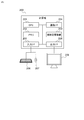
- FIG. 1 is an example of the overall configuration of the information processing system according to the first embodiment.
- the information system according to the first embodiment includes a client terminal 101, a request reception server 103 connected to the client terminal 101 via the network 102, and a data management server 104 connected to the request reception server 103 via the network 105, An application management server 110, a cluster management server 120, and a plurality of processing servers 130 are included.
- the client terminal 101 and other servers (request reception server 103, data management server 104, application management server 110, cluster management server 120, and processing server 130) are connected to different networks (102, 105).
- the information processing system may be configured such that the client terminal 101 and other servers are connected to the same network.
- the client terminal 101 is a terminal used by an application user.
- the application user creates input data to be processed by an application program (hereinafter abbreviated as “application”), and the application receives the application on the request reception server 103. Is used to transmit the processing request together with the input data.
- the client terminal 101 is, for example, a personal computer or server in a company or factory.
- the client terminal 101 may be a communication device having a communication function such as a smartphone or a tablet terminal.
- the network 102 is a wireless network or a wired network provided by a communication carrier or the like.
- the network 102 may include a network owned by an individual company or the like as a part of the network 102, or may be a network that allows a plurality of types of protocols to pass.
- the request reception server 103 receives a processing request such as an application execution request from the client terminal 101, and makes a processing request to the data management server 104, the application management server 110, the cluster management server 120, and the processing server 130 based on the received processing request.
- the server executes processing for returning the processing result to the client terminal 101.
- the data management server 104 is a server that stores data (input data) to be processed when an application is executed.
- the data management server 104 is a shared file server.
- the input data is stored as a record, a structure database server, json
- the server stores data such as an unstructured database such as a key-value store.
- the application management server 110 is a server that manages information on an application executed on the processing server 130 and calculates an estimated value of the execution processing time of the application by setting input data and computer resources.
- the application management server 110 includes an application management storage unit 111 that manages application information, and an application execution time calculation unit 112 that calculates an application execution time in advance based on input data and a computer resource amount. Details will be described with reference to FIGS.
- the cluster management server 120 is a server that manages the usage state of each processing server 130 and dynamically creates / destroys a cluster.
- the node-cluster management information storage unit 121, the cluster generation unit 122, and the cluster discard unit 123 Have.
- a set of computer resources (or a set of processing servers 130 having this computer resource) used when executing one application is called a “cluster”. Details will be described with reference to FIGS. 5, 7, and 8.
- the processing server 130 is a server for executing an application managed by the application management server 110, and includes an application management unit 131 that stores an execution code of the application, and a parallel processing management unit 132 that realizes parallel processing of the application. Have.
- a plurality of applications may be registered in the application management unit 131. When a plurality of applications are registered, a cluster is generated for each application processing request. Therefore, the processing server 130 belongs to a plurality of clusters, and application processing is performed from the processing server 130 in each cluster. Will be allocated. Details will be described with reference to FIG.
- these servers do not necessarily have to be different computers, and the functional units possessed by some of the servers described above may be implemented on a single computer.
- a single computer referred to as a “management server”.
- the functional units included in the request reception server 103, the data management server 104, the application management server 110, and the cluster management server 120 described above may be provided on the management server.
- one (or a plurality) of processing servers may be used as the management server.
- software for providing a so-called virtual computer is executed on one or a plurality of computers provided in the information processing system.
- a virtual machine that serves as a request receiving server a virtual machine that serves as a data management server
- a virtual machine that serves as an application management server a virtual machine that serves as a cluster management server
- the information processing system It may be configured.
- FIG. 2 is a diagram illustrating a physical configuration of the request reception server 103, the data management server 104, the application management server 110, the cluster management server 120, the processing server 130, and the client terminal 101 illustrated in FIG.
- a computer 200 having a processor (CPU) 201, a memory 202, an auxiliary storage device 203, and a communication interface (communication I / F) 204 is used for these servers (or client terminals).
- this computer may be a general-purpose computer such as a personal computer (PC).
- PC personal computer
- the processor 201 executes a program stored in the memory 202.
- the number of processors 201 is not necessarily one.
- the computer 200 may have a plurality of processors 201.
- the processor 201 may be a so-called multi-core processor having a plurality of processor cores.
- the memory 202 includes a ROM that is a nonvolatile storage element and a RAM that is a volatile storage element.
- the ROM stores an immutable program (for example, BIOS).
- BIOS basic BIOS
- the RAM is a high-speed and volatile storage element such as DRAM (Dynamic Random Access Memory), and temporarily stores a program executed by the processor 201 and data used when the program is executed.
- the auxiliary storage device 203 is a large-capacity non-volatile storage device such as a magnetic storage device (HDD) or a flash memory (SSD), and stores a program executed by the processor 201 and data used when the program is executed. To do. That is, the program is read from the auxiliary storage device 203, loaded into the memory 202, and executed by the processor 201.
- HDD magnetic storage device
- SSD flash memory
- the communication interface 204 is a network interface device that controls communication with other devices according to a predetermined protocol.
- the computer 200 may also include an input interface (input I / F) 205 and an output interface (output I / F) 208.
- the input interface 205 is an interface that is connected to a keyboard 206, a mouse 207, and the like and receives input from an operator.
- the output interface 208 is an interface to which a display device 209, a printer, or the like is connected, and the execution result of the program is output in a form that can be visually recognized by the operator.
- each functional unit of the application management server 110, the cluster management server 120, and the processing server 130 is implemented by software (program).
- a program for causing the application management server 110 to function as the application management storage unit 111 and the application execution time calculation unit 112 is loaded on the memory 202 of the application management server 110 (computer 200), and the processor 201. It is executed by.
- the application management server 110 operates as a device having the application management storage unit 111 and the application execution time calculation unit 112.
- the processor 201 of the computer 200 executes a program for realizing each functional unit described above.
- the cluster management server 120 and the processing server 130 operate as devices having the above-described functional units.
- the description will be made with functional units such as the application execution time calculation unit 112 and the cluster generation unit 122 as the subject. In practice, this means that the processor 201 of the computer 200 having a functional unit performs processing.
- the program executed by the processor 201 is provided to the computer 200 via a computer-readable storage medium or network, and is stored in the auxiliary storage device 203 which is a non-temporary storage medium.
- the computer-readable storage medium is a non-transitory computer-readable medium, such as a non-volatile removable medium such as a CD-ROM or flash memory.
- the computer 200 preferably has an interface for reading data from a removable medium.
- some or all of the functional units may be implemented using hardware such as FPGA or ASIC.
- FIG. 3 is a diagram outlining the mechanism when an application is executed on the processing server 130.
- the processing server 130 manages the application management unit 131 in which the application is arranged and the processing server 130 in the same cluster, and manages the parallel execution of the application while allocating the processing to each processing server 130. And a parallel processing management unit 132.
- the application management unit 131 is a functional unit that stores application programs, and holds application programs using the storage areas of the memory 202 and the auxiliary storage device 203.
- the parallel processing management unit 132 provides various functions necessary for executing applications in parallel. Prior to the description of the parallel processing management unit 132, how the application is executed in parallel on the processing server 130 will be outlined.
- an example in which an application is a program for analyzing data will be described as an example.
- the application includes program code (execution code) for executing one or more processes.
- Reference numeral 410 in FIG. 4 indicates a configuration example of the application (App A).
- App A includes a plurality of processes Aa, Ab, and Ac, and when App A is executed on the process server, the processes are executed in the order of processes Aa, Ab, and Ac.
- the process Aa is a process for normalizing input data
- the process Ab is a process for analyzing normalized data
- the process Ac is a statistical process for data analyzed in the process Ab.
- Some processes may be processed in parallel by a plurality of processing servers 130 (or a plurality of processors 201).
- a plurality of processing servers 130 or a plurality of processors 201.
- the processes Aa and Ab are processes that can be executed in parallel will be described.
- An application executes code for causing the processor 201 to execute each of these processes (Aa, Ab, Ac), and an execution code for causing the processor 201 to execute (distribute) each process server 130 to execute (distribute) each process.
- the former execution code is called an “execution unit” (312 in FIG. 3)
- the latter execution code is called a “distribution unit” (311 in FIG. 3).
- the information transmitted by the distribution unit 311 to request each processing server 130 for processing of the execution unit is referred to as a “message”.
- a plurality of processes (Aa, Ab, Ac) are executed as in App A shown in FIG. 3 or FIG.
- the execution unit 312 executes an execution code and a process Ab.
- An execution code and an execution code for performing processing Ac are included.
- the execution codes that perform the processes Aa, Ab, and Ac are referred to as “code Aa”, “code Ab”, and “code Ac”, respectively.
- the parallel processing management unit 132 of the processing server 130 manages parallel execution of applications that are separately designed and defined in the form of a distribution unit 311 and an execution unit 312.
- the parallel processing management unit 132 receives an application execution request from the outside such as the request reception server 103 and starts the execution of the application distribution unit 311 and a message generated by the distribution unit 311.
- the message distribution unit 322 transmitted to the processing server (execution) 130, the message received from the processing server (distribution) 130 are analyzed, and the execution code (code Aa, Ab, Ac) included in the target execution unit 312 is analyzed.
- the message reception unit 323 to be called executes applications in parallel.
- the parallel processing management unit 132 receives an application deployment or undeployment request from the cluster management server 120 or the like, and arranges and deletes applications in the application management unit 310, and an application management unit. Also provided is a function of a cluster information storage unit 325 that manages cluster information about a cluster to which an application arranged in 310 belongs. The cluster information will be described later.
- the parallel processing management unit 132 performs processing such as transmission / reception of this message and execution of processing by the execution unit based on the received message.
- processing such as transmission / reception of this message and execution of processing by the execution unit based on the received message.
- the flow of processing when App A310 is executed will be outlined with reference to FIG.
- N and M are both integers of 1 or more, where N and M are May be equal.
- the processing server 130 that is responsible for the distribution unit 311 that generates and distributes the message is the processing server (distribution) 130
- the processing server that is responsible for the execution unit 312 that receives the message and executes the processing. 130 is referred to as a processing server (execution) 130.
- the processing server (execution) 130 and the processing server (distribution) 130 may be the same server.
- the distribution unit 311 of the processing server (distribution) 130 first generates N messages Aa, and the intra-cluster via the message distribution unit 322 of the parallel processing management unit 132
- the message Aa is transmitted to each processing server 130.
- the distribution server 311 determines the processing server 130 that is the transmission destination of the message Aa.
- the message receiving unit 323 calls a code for executing the processing Aa in the execution unit 312 corresponding to the message Aa, and executes the processing Aa. After executing the process Aa, the message receiving unit 323 returns the process result to the process server (distribution) 130.
- the distribution unit 311 of the processing server (distribution) 130 When the distribution unit 311 of the processing server (distribution) 130 receives N processing result replies corresponding to the message Aa, it generates M messages Ab as the next processing, and the parallel processing management unit 132 similarly.
- the message Ab is transmitted to the processing server (execution) 130 in the cluster via the message distribution unit 322.
- the allocating unit 311 For each process (Aa, Ab, Ac), the allocating unit 311 transmits a message and receives a result, and when receiving a result corresponding to the message Ac, the application ends. That is, the application can be designed and defined separately for the distribution unit 311 that generates a message to be processed and the execution unit 312 that receives the message, so that the repeated processing part can be processed in parallel.
- the processing server 130 By simply placing an application on the processing server 130 by the parallel processing management unit 132 and transmitting an execution request to one of the processing servers 130 in the cluster, the processing server 130 automatically executes the processing server (translation server). Minute) 130 and processing server (execution) 130, and the processing of the application can be executed in parallel while being distributed to the processing server (execution) 130. The flow of these processes will be described later with reference to the sequence diagrams of FIGS.
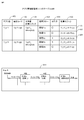
- FIG. 4 is a diagram illustrating an example of a table of the application management storage unit 111 held in the application management server 110.
- the application management storage unit 111 is a functional unit that stores execution code to be arranged as an application, processing flow information for calculating the processing time of the application, and calculation logic information for calculating the execution time for each processing. In order to store such information, the storage area of the memory 202 or the auxiliary storage device 203 is used.
- the application management storage unit 111 may be implemented using a known file system program or a program such as a database management system (DBMS). In this embodiment, an example will be described in which the application management storage unit 111 stores application execution code, processing flow, and calculation logic information in a table formed on the storage area of the memory 202 or the auxiliary storage device 203.
- DBMS database management system
- the table 400 included in the application management storage unit 111 has six columns as shown in FIG. Hereinafter, information stored in each column will be described.
- the application name 401 stores the name of the application.
- the name of an application is a name used to identify an application when an application user requests execution of the application.
- an execution code (file) of the application corresponding to the application name 401 is stored.
- the parallel degree calculation logic 403 stores a file in which logic for calculating the number of repetitions of each process of the application according to the input data amount is described. In this embodiment, the logic for calculating the number of repetitions of each process is called “parallel degree calculation logic”.
- the process flow 404 records the process execution procedure of the application.
- the parallelism 405 stores information indicating whether each process described in the process flow 404 can be executed in parallel.
- the calculation logic 406 stores a file in which calculation logic for calculating one execution time of each process in the processing flow 404 (referred to as “execution time calculation logic”) is described.
- the application stored in the first row of the table of FIG. 4 includes three processes of process Aa, process Ab, and process Ac as described in 410 of FIG. Assume that processing is performed in the order of processing Ab and processing Ac.
- the processing Aa and the processing Ab can be executed in parallel, and the number of repeated executions varies according to the amount of input data given.
- the parallelism calculation logic 403 has a file name of a file in which logic for calculating the number of times of repetition of the processing Aa and the processing Ab is calculated from the amount of input data (“AppA_message.py” in the example of FIG. 4). Is described.
- “process Aa, process Ab, process Ac” are described.
- the row in which “Processing Aa” is stored in the column of the processing flow 404 is “Row 407”
- the row in which “Processing Ab” is stored is “Row 408”
- the row in which “Processing Ac” is stored is “ Call line 409 ".
- the file describing the execution time calculation logic of process Aa is “AppA_calcAa.py”
- the file describing the execution time calculation logic of process Ab is “AppA_calcAb.py”
- the execution time calculation logic of process Ac is described. If the file is “AppA_calcAc.py”, “AppA_calcAa.py” is stored in line 407, “AppA_calcAb.py” is stored in line 408, and “AppA_calcAc.py” is stored in line 409 in the column of calculation logic 406.
- the information stored in the table of the application management storage unit 111 is registered in advance in the application management storage unit 111 by an information processing system administrator or an application user.
- the parallelism calculation logic and the execution time calculation logic are created in advance by an application developer.
- the information processing system may be provided with means for automatically creating the execution time calculation logic. For example, considering the causal relationship between the amount of data and execution time, the function that statistically processes input data and automatically creates calculation logic, and analyzes items that have a causal relationship with execution time in addition to the amount of data
- the information processing system has a function of automatically building a prediction model of calculation logic, and when the application is registered in the application management server 110, the information processing system generates an execution time calculation logic, and an application management storage unit 111 may be registered.
- the executable code and the calculation logic file name (AppA.app, etc.) are described in the columns of the execution code 402, the parallelism calculation logic 403, and the calculation logic 406 for easy understanding.
- the file entity is also stored in these columns.
- the execution code and the calculation logic file entity are stored in the application management storage unit 111 (the storage area of the auxiliary storage device 203 constituting the execution code 402), the parallelism calculation logic 403, and the calculation.
- the logic 406 column may store the path name of each file.
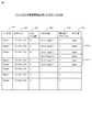
- FIG. 5 is a diagram illustrating an example of a table of the node-cluster management information storage unit 121 held in the cluster management server 120.
- the node-cluster management information storage unit 121 stores various types of information in a table formed on the storage area of the memory 202 or the auxiliary storage device 203 as in the case of the application management storage unit 111 will be described.
- the node-cluster management information storage unit 121 manages information of all processing servers 130 to which applications can be arranged, and among these processing servers 130, the same application is arranged to form a cluster. Information on the processing server 130 is also stored and managed in the table 500.
- Each row (record) of the table 500 included in the node-cluster management information storage unit 121 has six columns as shown in FIG. 5, and each record stores information about the processing server 130 in the information processing system.
- the node name 501 is a column for storing the name of the processing server 130.
- Each processing server 130 has a unique name in the information processing system, and in the present embodiment, the name is referred to as a “node name”.
- the IP address 502 stores the IP address of the processing server 130 specified by the node name 501.
- the number of CPU cores 503 stores the number of processor cores (CPU cores) that the processing server 130 has.
- the cluster name 504 stores the name of the cluster to which the processing server 130 belongs
- the assigned CPU core number 505 stores the number of processor cores assigned to the cluster. Therefore, by calculating the difference between the CPU Core number 503 and the assigned CPU Core number 505, the number of processor cores (referred to as “unused cores”) that are not yet assigned to any cluster is obtained.
- the application name 506 stores the application name of the application arranged in the processing server 130.
- the processing server 130 is described as having a so-called multi-core processor.
- the processor of the processing server 130 is a single core processor
- the CPU Core number 503 and the assigned CPU Core number 505 include a processor.
- the number of processors is stored instead of the number of cores.
- cluster information information included in the set of records having the same cluster name 504, particularly information in the columns 504 to 506 of these records, This is called “cluster information”.
- columns 504 to 506 in the rows 510-1 and 510-2 are the cluster information of the cluster “User1-AppB-1” and the cluster information of the cluster “User2-AppA-5”, respectively.
- the cluster information it is possible to know the number of processing servers 130 and CPU Cores belonging to the cluster.
- the processing server 130 to be assigned to the cluster is selected from the table 500.
- the cluster generation unit 122 stores information such as the cluster name and the number of CPU cores to be used in the columns 504 to 506 of the record corresponding to the selected processing server 130.
- a process in which the cluster generation unit 122 stores information such as a cluster name in the columns 504 to 506 is referred to as a “create cluster information” process.
- creating cluster information it means that computer resources used to execute applications are substantially reserved (reserved).
- the created cluster information is also arranged in the cluster information storage unit 325 of the processing server 130.
- the cluster discarding unit 123 deletes information such as the cluster name from the columns 504 to 506. This process is called a “deletion of cluster information” process.
- the cluster information By deleting the cluster information, the computer resources reserved for executing the application are substantially released, and the released computer resources can be used for other purposes.
- a computer resource on the cloud (not shown) is used as the processing server 130, that is, when a computer resource on the cloud is reserved and used for each cluster generation request, the node is stored each time the computer resource is reserved. -When a record is added to the table of the cluster management information storage unit 121 and the execution of the application is completed and the cluster is deleted, the record is deleted.
- the processing server 130 holds a plurality of CPU Cores and the degree of parallelism of the application is less than the number of CPU Cores of the processing server 130, a plurality of applications may be arranged on one processing server 130. possible. In that case, the processing server 130 belongs to a plurality of clusters.
- the cluster generation unit 122 (described later) of the cluster management server 120 sets the processing server 130 having an unused core as 1 or Select multiple. At that time, the cluster generation unit 122 selects the processing server 130 so that the number of unused cores included in the selected processing server 130 is four (or more).
- the processing servers 130 of Node 1 to Node 8 exist and the CPU Core of Node 1 to Node 5 has already been assigned to some application, it is not used.
- Node 5 and Node 6 may be selected as the processing server 130 having two or more cores.
- the cluster generation unit 122 may secure a computer resource (CPU Core) by adding 2 to the allocation CPU Core 505 of Node 5 and Node 6.
- one or more processing servers 130 may be selected in consideration of the amount of memory and the processing performance of the CPU.
- FIG. 6 is an example of an operation flow of the application execution time calculation unit 112 of the application management server 110.
- the application execution time calculation unit 112 receives an application execution time calculation request specifying an application name, input data, and parallelism as arguments from a request issuer (step 601).
- the request issuer of the application execution time calculation request is the request reception server 103.
- the degree of parallelism may be specified for each process constituting the application. For example, if the application is composed of processes Aa, Ab, and Ac as shown by 410 in FIG. 4 and the processes Aa and Ab are processes that can be executed in parallel, the request issuing source is the parallel degree of the process Aa and the parallel of the process Ab.
- An application execution time calculation request specifying the degree as an argument may be issued to the application execution time calculation unit 112.
- n be the degree of parallelism.
- the application execution time calculation unit 112 acquires the parallelism calculation logic 403 corresponding to the application name and the calculation logic 406 corresponding to each process in the processing flow 404 from the application management storage unit 111 (step 602). Then, the application execution time calculation unit 112 calculates the number of repetitions of each process of the application from the input data amount using the parallel degree calculation logic 403 (step 603), and then uses the calculation logic 406 of each process. The execution time when each process executes the process corresponding to the input data once is calculated (step 604).
- the application execution time calculation unit 112 uses the number of repetitions of each process obtained in step 603 and the execution time of each process obtained in step 604 to execute the application execution time (perform parallel processing). (Execution time when there is no) (step 605), and when a group of processes that can be executed in parallel is executed in parallel, the number of repetitions of each process, the execution time of each process, and the total execution time of the application are calculated, The execution result is returned to the request issuer (step 606).
- the number of repetitions and the execution time are the number of repetitions of each process obtained in step 603 and the execution time of each process obtained in step 604, respectively. determined by dividing by n).
- the application execution time calculation unit 112 executes the flow described above to instantaneously calculate the application execution time from the input data and parallelism, and presents information on the calculation time to the application user. As a result, the application user can determine the parallelism with respect to the allowable execution time by trial and error.
- FIG. 7 is an example of an operation flow of the cluster generation unit 122 of the cluster management server 120.
- the cluster generation unit 122 receives a cluster generation request issued from the request issuer (step 701).
- the request issuing source of the cluster generation request is the request receiving server 103.
- the cluster generation request includes the application name and the degree of parallelism as arguments.
- the cluster generation unit 122 looks at the node-cluster management information storage unit 121 and generates a cluster name having a name that has not yet been recorded in the node-cluster management information storage unit 121, so that A unique name is assigned (step 702).
- the cluster generation unit 122 refers to the node-cluster management information storage unit 121 to select one or a plurality of processing servers 130 having processor cores that are not yet assigned to any cluster (step 703).
- Cluster information is created in the cluster management information storage unit 121 (step 704). Since the selection method of the processing server 130 in step 703 has been described with reference to FIG. 5, description thereof is omitted here.
- the cluster generation unit 122 acquires the execution code 402 of the application corresponding to the application name from the application management server 110 in order to place the application on the selected processing server 130, and requests each processing server to place the application. (Steps 705 and 706). The processing performed by the processing server 130 for which application placement has been requested will be described later.
- the cluster generation unit 122 selects the processing server 130 to be the processing server (distribution) 130 from the processing servers 130 in which the execution code 402 of the application is arranged (Step 707), and the cluster name and the processing server ( An access URL (Uniform Resource Locator) to the (distribution) 130 is returned to the request issuer (step 708).
- the cluster name and the processing server An access URL (Uniform Resource Locator) to the (distribution) 130 is returned to the request issuer (step 708).
- FIG. 8 is an example of an operation flow of the cluster discard unit 123 of the cluster management server 120.
- the cluster discard unit 123 accepts a cluster discard request in which the cluster name is specified as an argument from the request issuer (step 801). Again, the request issuer is the request reception server 103.
- the cluster discarding unit 123 acquires information on the processing servers 130 in the cluster from the node-cluster management information storage unit 121 (Step 802), and causes each processing server 130 to delete the application (Step 803).
- the cluster discarding unit 123 deletes the cluster information in the node-cluster management information storage unit 121 (step 804), and returns a completion notification to the request issuer (step 805).
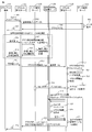
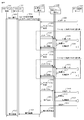
- FIG. 9 is a sequence diagram showing the flow of processing performed in each server in the information processing system when the application user requests execution of the application using the information processing system according to the present embodiment.
- FIG. 9 describes the flow of processing from when the client terminal 101 issues a request to the request reception server 103 until a cluster for executing the application is generated.
- the client terminal 101 transmits an application registration request to the request reception server 103 (901).
- This application registration request includes an application name (for example, “AppA”) and input data.
- the request reception server 103 first registers input data in the data management server 104 (902, 903).
- the data management server 104 receives the input data
- the data management server 104 returns an access URL (904) as an access method to the input data to the request reception server 103.
- the request reception server 103 Upon receiving the access URL (904), the request reception server 103 returns OK (905) to the client terminal 101.
- the request reception server 103 holds the URL to the input data and the application name in association with each other.
- the application user designates the degree of parallelism (906) using the client terminal 101.
- the request reception server 103 causes the application execution time calculation unit 112 of the application management server 110 to calculate the number of repetitions and the execution time of each process (907, 908, 909), and the result is the client terminal 101. (910).
- the processing performed by the application management server 110 in steps 907, 908, and 909 corresponds to the processing in FIG.
- the application user repeats the processing from 906 to 910 while changing the degree of parallelism until the application execution time calculated by the application execution time calculation unit 112 falls within the time desired by the application user. For example, when the execution time of an application calculated when a certain degree of parallelism (assumed to be n) is specified is longer than the execution time desired by the application user, the application user has a degree of parallelism higher than n ( For example, (n + 1) or the like may be designated and the application execution time calculation unit 112 may calculate the application execution time.
- the application user has a degree of parallelism lower than the initially specified degree of parallelism (n) (for example, (n-1), etc. ) May be designated to cause the application execution time calculation unit 112 to calculate the application execution time.
- n initially specified degree of parallelism
- the application user determines the degree of parallelism when the application is actually executed by repeating the processing of 906 to 910 described above (hereinafter, the degree of parallelism determined by the application user is referred to as “runtime parallelism”.
- the degree of parallelism designated by the application user in 906 in FIG. 9 is distinguished).
- the application user transmits a cluster generation request specifying the runtime parallelism and the application name from the client terminal 101 to the cluster management server 120 via the request reception server 103 (911, 912). ).
- a specific method for the application user to specify the degree of parallelism in this processing will be described later with reference to FIG. 12 (or FIG. 13).
- the cluster management server 120 receives the cluster generation request (912), the cluster generation unit 122 creates a cluster name (913), and secures the computer resource (CPU Core) of the processing server 130 according to the parallelism at the time of execution.
- cluster information is created in the node-cluster management information storage unit 121 (915). Processes 912 to 915 are processes corresponding to steps 701 to 704 in FIG.
- the cluster generation unit 122 acquires the execution code (916) of the application from the application management server 110 (917), and requests each processing server 130 to arrange the application (918).
- Processes 917 to 918 are processes corresponding to steps 705 to 706 in FIG.
- the cluster generation unit 122 requests the processing server 130 to place an application, the execution code of the application and cluster information are transmitted to the processing server 130.
- the processing server 130 requested to arrange the application installs the application (919) and creates cluster information in the cluster information storage unit 325 of the parallel processing management unit 132 (920).
- the cluster management server 120 includes one processing server 130 that becomes the processing server (distribution) 130 among the processing servers 130 belonging to the cluster.
- the access URL to the processing server (distribution) 130 is returned to the request receiving server 103 together with the cluster name (923).
- the request reception server 103 returns OK (924) to the client terminal 101, and the processing is completed.
- FIG. 10 is an example of an operation sequence for executing application processing in parallel using the processing server 130 group determined by the processing in FIG. 9 following the processing in FIG. 9.
- the request reception server 103 receives input data for an access URL to the processing server (distribution) 130.
- An execution request is transmitted together with the access URL (1002).
- the request reception server 103 returns OK to the client terminal 101 (924), and then the application user issues an application execution request (1001).
- an execution request is transmitted (1002) to the processing server (distribution) 130.
- the request receiving server 103 sends a reply (924) to the client terminal 101.
- the application execution request may be transmitted (1002) to the processing server (distribution) 130.
- the application distribution unit 311 In the processing server (distribution) 130, the application distribution unit 311 generates the same number of messages Aa as the degree of parallelism (runtime parallelism) specified in 911 (1004), and each message Aa (1005) It is transmitted to the processing server (execution) 130.
- the processing server (distribution) 130 acquires the input data from the data management server 104 (1003).
- the processing server (execution) 130 When the processing server (execution) 130 receives the message Aa, the processing server (execution) 130 acquires target data (1006) necessary for the processing Aa from the input data stored in the data management server 104, and executes the processing Aa of the execution unit 312. Then, the processing result (1008) is written in the data management server 104 and a processing completion notification (1009) is returned to the processing server (distribution) 130.
- the processing server (distribution) 130 When the processing server (distribution) 130 receives completion notifications from all the processing servers (execution) 130 that transmitted the message (1009), it generates the next message (“message Ab” in the example of FIG. 10), Allocate to each processing server (execution) 130. In this way, the processing server (distribution) 130 repeats the process of generating a message, distributing the message to each processing server (execution) 130, and receiving a processing completion notification from each processing server (execution) 130. When the processing server (distribution) 130 receives a processing completion notification for the last message (“message Ac” in the example of FIG.
- the processing server (distribution) 130 acquires the final result from the data management server 104. (1022) An execution result as an application is generated (1023), and the execution result (1024, 1025) is returned to the client terminal 101 via the request reception server 103.
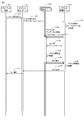
- FIG. 11 shows an example of processing performed after FIG. 10, that is, processing from the end of application execution until the cluster is discarded.
- the request reception server 103 receives an application execution completion notification (1101) from the client terminal 101, the request reception server 103 transmits a cluster destruction request (1102) to the cluster management server 120, and a cluster destruction unit. 123 accepts this cluster discard request.
- This process corresponds to step 801 in FIG.
- the cluster discard request includes the cluster name to be discarded.
- the cluster destruction unit 123 refers to the node-cluster management information storage unit 121 to identify the processing server 130 and the application name in the cluster (1103). This process corresponds to step 802. Then, the cluster discard unit 123 transmits an application discard request (1104) to each identified processing server 130 (a process corresponding to step 803).
- each processing server 130 Upon receiving the application discard request, each processing server 130 uninstalls the application (1105), discards the cluster information recorded in the cluster information storage unit 325 (1106), and then sends a completion notification to the cluster management server 120. Return it.
- the cluster discard unit 123 receives the completion notification (1107) from each processing server 130, the cluster information in the node-cluster management information storage unit 121 is deleted (1108), and the completion notification is sent to the client terminal 101 via the request reception server 103. (1109, 1101) is returned.
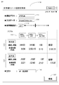
- FIG. 12 is an example of a computer resource amount setting screen image for the application user to determine the computer resource amount for each execution request.
- the request reception server 103 creates this setting screen 1200 and provides it to the client terminal 101 (displayed on the display device 209 of the client terminal 101).
- a computer other than the request reception server 103 may create the setting screen 1200.
- 1201 is an application name input box
- 1202 is a data name input box
- 1206 is a parallel degree setting column.
- the request reception server 103 performs each process in the processing flow when parallel processing is not performed first based on the application name input by the application user in the application name input box 1201 and the data name input box 1202 and the registered input data.
- the application execution time calculation unit 112 is caused to calculate the number of repetitions, the expected value of the processing time of each process, and the total execution time of each process (the process up to step 605 in FIG. 6 is performed).
- the request reception server 103 creates a screen for displaying the calculated information (1204) in association with the application processing flow (1203), and causes the display device 209 of the client terminal 101 to output this screen.
- the application management server 110 When the application user inputs the parallel degree in the parallel degree setting field 1206 based on the displayed information, the input parallel degree is transmitted to the application management server 110. As described above with reference to FIGS. 6 and 9, the application management server 110 performs the parallel processing using the passed degree of parallelism or the like, the number of repetitions of each process, the expected value of the processing time, and the application The total execution time is obtained, and a screen displaying the result in the display area (1205) is created and displayed on the client terminal 101. Therefore, the application user gradually increases the parallelism input in the parallelism setting field 1206 until the total execution time of the application displayed in the display area (1205) is within the execution time desired by the application user. It is good to repeat.
- the computer resource amount setting screen 1200 is provided with a cost display field (1208), and the request reception server 103 (or application management server 110) determines the parallelism of the application and the execution time of the application (execution time when the application is executed in parallel). ) (Information processing system usage fee) may be calculated, and the calculated cost information may be provided to the application user.
- the application user can determine the parallelism (runtime parallelism) that satisfies the current execution request while observing the balance between the execution time for completing the application and the cost required according to the parallelism.
- the request reception server 103 receives from the client terminal 101 the application name and parallelism (runtime parallelism) set by the application user in the application name input box 1201 and the parallelism setting field 1206. Then, the request reception server 103 transmits a cluster generation request specifying the execution parallelism and the application name to the cluster management server 120 (the processing of 911 and 912 in FIG. 9 is performed).
- the request reception server 103 transmits an application execution request to the processing server (distribution) 130 (FIG. 9). 10 1002).
- the information processing system includes the functions described above, thereby generating an execution environment of a parallel computing system that satisfies the execution request for each execution request, and executing the applications in parallel.
- Example 2 describes an example of an information processing system that can set the degree of parallelism for each process of an application. Since the configuration of the information processing system according to the second embodiment is the same as that described in the first embodiment, description of the configuration is omitted, and only differences from the content described in the first embodiment will be described.
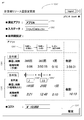
- FIG. 13 shows an example of a computer resource amount setting screen 1200 'according to the second embodiment.
- the setting screen 1200 ′ in FIG. 13 differs from the setting screen 1200 described in FIG. 12 in that the setting screen 1200 ′ in FIG. 13 includes a parallel degree setting column for each process that can be executed in parallel (FIG. 13: 1206). 'And 1206' '), the application user can set the degree of parallelism for each process. Further, when the application management server 110 calculates the execution time of the application, the calculation is performed based on the degree of parallelism set for each process on the setting screen 1200 ′′.
- the parallelism can be set for each process of the application, so that when the processing time for each process is different, the application user By increasing the setting, the effect of shortening the total execution time is great, and it becomes possible to select measures that minimize the cost as much as possible.
- the degree of parallelism for each process for example, by setting the total execution time after parallelization, the degree of parallelism for each process is calculated, and the cost is set. Accordingly, a method for setting the degree of parallelism is also conceivable in which the setting of the degree of parallelism of each process is calculated so that the execution time is shortened accordingly.
- the application user can determine the amount of computer resources desired by the application user from the viewpoint of total execution time, cost, etc. It is possible to provide an execution environment of a parallel computing system in which a user can immediately execute an application in parallel.
- the method of specifying input data from the client terminal 101 when an application execution request is made has been described.
- data is registered in the data management server 104 in advance, At this time, the application user may process the input data by designating the data stored in the data management server 104 as the input data.
- 101 Client terminal, 102: Network, 103: Request reception server, 104: Data management server, 110: Application management server, 120: Cluster management server, 130: Processing server
Abstract
Le but de la présente invention est de fournir un système informatique parallèle qui est apte à déterminer des quantités de ressources informatiques qui sont requises pour chaque demande d'exécution par un utilisateur d'application, et à sécuriser les ressources informatiques pour chaque exécution. Un système de traitement d'informations selon un mode de réalisation de la présente invention comprend un serveur de gestion et une pluralité de serveurs de traitement qui comprennent chacun en outre un ou plusieurs processeurs pour exécuter des programmes d'application. Lors de la réception d'une simultanéité d'un programme d'application provenant d'un utilisateur, le serveur de gestion sécurise, parmi les ressources informatiques utilisables que la pluralité de serveurs de traitement comprend, les ressources informatiques qui sont nécessaires pour exécuter le programme d'application au niveau de la simultanéité reçue, positionne le programme d'application sur le serveur de traitement qui comprend les ressources informatiques sécurisées, et amène le serveur de traitement à effectuer une exécution parallèle du programme d'application.
Applications Claiming Priority (2)
| Application Number | Priority Date | Filing Date | Title |
|---|---|---|---|
| JP2016-208345 | 2016-10-25 | ||
| JP2016208345A JP6796994B2 (ja) | 2016-10-25 | 2016-10-25 | 情報処理システム |
Publications (1)
| Publication Number | Publication Date |
|---|---|
| WO2018079162A1 true WO2018079162A1 (fr) | 2018-05-03 |
Family
ID=62024696
Family Applications (1)
| Application Number | Title | Priority Date | Filing Date |
|---|---|---|---|
| PCT/JP2017/034689 WO2018079162A1 (fr) | 2016-10-25 | 2017-09-26 | Système de traitement d'informations |
Country Status (2)
| Country | Link |
|---|---|
| JP (1) | JP6796994B2 (fr) |
| WO (1) | WO2018079162A1 (fr) |
Families Citing this family (4)
| Publication number | Priority date | Publication date | Assignee | Title |
|---|---|---|---|---|
| JP7471091B2 (ja) | 2020-01-22 | 2024-04-19 | 株式会社日立製作所 | ジョブ実行支援システム、及びジョブ実行支援方法 |
| JP7340663B1 (ja) | 2022-07-13 | 2023-09-07 | 株式会社三菱Ufj銀行 | リソース申請システム |
| JP7421606B1 (ja) | 2022-07-13 | 2024-01-24 | 株式会社三菱Ufj銀行 | リソース申請システム |
| JP7318084B1 (ja) | 2022-09-20 | 2023-07-31 | 株式会社三井E&S | 統括装置及び統括プログラム |
Citations (2)
| Publication number | Priority date | Publication date | Assignee | Title |
|---|---|---|---|---|
| JP2015146154A (ja) * | 2014-02-04 | 2015-08-13 | 富士通株式会社 | ジョブスケジューリング装置、ジョブスケジューリング方法、およびジョブスケジューリングプログラム |
| WO2016079802A1 (fr) * | 2014-11-18 | 2016-05-26 | 株式会社日立製作所 | Système de traitement par lots, et procédé de commande correspondant |
-
2016
- 2016-10-25 JP JP2016208345A patent/JP6796994B2/ja active Active
-
2017
- 2017-09-26 WO PCT/JP2017/034689 patent/WO2018079162A1/fr active Application Filing
Patent Citations (2)
| Publication number | Priority date | Publication date | Assignee | Title |
|---|---|---|---|---|
| JP2015146154A (ja) * | 2014-02-04 | 2015-08-13 | 富士通株式会社 | ジョブスケジューリング装置、ジョブスケジューリング方法、およびジョブスケジューリングプログラム |
| WO2016079802A1 (fr) * | 2014-11-18 | 2016-05-26 | 株式会社日立製作所 | Système de traitement par lots, et procédé de commande correspondant |
Also Published As
| Publication number | Publication date |
|---|---|
| JP2018072907A (ja) | 2018-05-10 |
| JP6796994B2 (ja) | 2020-12-09 |
Similar Documents
| Publication | Publication Date | Title |
|---|---|---|
| JP7092736B2 (ja) | コンテナオーケストレーションサービスを使用した動的ルーティング | |
| US9348709B2 (en) | Managing nodes in a distributed computing environment | |
| WO2018079162A1 (fr) | Système de traitement d'informations | |
| US8910128B2 (en) | Methods and apparatus for application performance and capacity analysis | |
| US20170123777A1 (en) | Deploying applications on application platforms | |
| US11467874B2 (en) | System and method for resource management | |
| Lin et al. | ABS-YARN: A formal framework for modeling Hadoop YARN clusters | |
| CN105786603B (zh) | 一种基于分布式的高并发业务处理系统及方法 | |
| US10331488B2 (en) | Multilayered resource scheduling | |
| US11068317B2 (en) | Information processing system and resource allocation method | |
| CN113382077B (zh) | 微服务调度方法、装置、计算机设备和存储介质 | |
| US8027817B2 (en) | Simulation management within a grid infrastructure | |
| US20190056942A1 (en) | Method and apparatus for hardware acceleration in heterogeneous distributed computing | |
| CN112241316A (zh) | 一种分布式调度应用的方法以及装置 | |
| Sundas et al. | An introduction of CloudSim simulation tool for modelling and scheduling | |
| JP2016115065A (ja) | 情報処理装置、情報処理システム、タスク処理方法、及び、プログラム | |
| US20180316572A1 (en) | Cloud lifecycle managment | |
| KR102519721B1 (ko) | 컴퓨팅 자원 관리 장치 및 방법 | |
| US10853137B2 (en) | Efficient resource allocation for concurrent graph workloads | |
| JP2017191387A (ja) | データ処理プログラム、データ処理方法およびデータ処理装置 | |
| TWI492155B (zh) | 利用雲端服務在行動裝置上執行應用的方法與系統 | |
| Nino-Ruiz et al. | Elastic scaling of e-infrastructures to support data-intensive research collaborations | |
| CN112219190A (zh) | 用于实时环境的动态计算资源指派和可扩展计算环境生成 | |
| Mosa et al. | Towards a cloud native big data platform using micado | |
| Yi et al. | MRM: mobile resource management scheme on mobile cloud computing |
Legal Events
| Date | Code | Title | Description |
|---|---|---|---|
| 121 | Ep: the epo has been informed by wipo that ep was designated in this application |
Ref document number: 17864754 Country of ref document: EP Kind code of ref document: A1 |
|
| NENP | Non-entry into the national phase |
Ref country code: DE |
|
| 122 | Ep: pct application non-entry in european phase |
Ref document number: 17864754 Country of ref document: EP Kind code of ref document: A1 |