WO2018076469A1 - 无人机及其电池组件、电池外壳 - Google Patents
无人机及其电池组件、电池外壳 Download PDFInfo
- Publication number
- WO2018076469A1 WO2018076469A1 PCT/CN2016/109002 CN2016109002W WO2018076469A1 WO 2018076469 A1 WO2018076469 A1 WO 2018076469A1 CN 2016109002 W CN2016109002 W CN 2016109002W WO 2018076469 A1 WO2018076469 A1 WO 2018076469A1
- Authority
- WO
- WIPO (PCT)
- Prior art keywords
- end cover
- battery
- casing
- limiting plate
- hole
- Prior art date
- Legal status (The legal status is an assumption and is not a legal conclusion. Google has not performed a legal analysis and makes no representation as to the accuracy of the status listed.)
- Ceased
Links
Images



Classifications
-
- H—ELECTRICITY
- H01—ELECTRIC ELEMENTS
- H01M—PROCESSES OR MEANS, e.g. BATTERIES, FOR THE DIRECT CONVERSION OF CHEMICAL ENERGY INTO ELECTRICAL ENERGY
- H01M50/00—Constructional details or processes of manufacture of the non-active parts of electrochemical cells other than fuel cells, e.g. hybrid cells
- H01M50/20—Mountings; Secondary casings or frames; Racks, modules or packs; Suspension devices; Shock absorbers; Transport or carrying devices; Holders
- H01M50/202—Casings or frames around the primary casing of a single cell or a single battery
-
- B—PERFORMING OPERATIONS; TRANSPORTING
- B64—AIRCRAFT; AVIATION; COSMONAUTICS
- B64D—EQUIPMENT FOR FITTING IN OR TO AIRCRAFT; FLIGHT SUITS; PARACHUTES; ARRANGEMENT OR MOUNTING OF POWER PLANTS OR PROPULSION TRANSMISSIONS IN AIRCRAFT
- B64D47/00—Equipment not otherwise provided for
-
- H—ELECTRICITY
- H01—ELECTRIC ELEMENTS
- H01M—PROCESSES OR MEANS, e.g. BATTERIES, FOR THE DIRECT CONVERSION OF CHEMICAL ENERGY INTO ELECTRICAL ENERGY
- H01M50/00—Constructional details or processes of manufacture of the non-active parts of electrochemical cells other than fuel cells, e.g. hybrid cells
- H01M50/20—Mountings; Secondary casings or frames; Racks, modules or packs; Suspension devices; Shock absorbers; Transport or carrying devices; Holders
- H01M50/262—Mountings; Secondary casings or frames; Racks, modules or packs; Suspension devices; Shock absorbers; Transport or carrying devices; Holders with fastening means, e.g. locks
-
- H—ELECTRICITY
- H01—ELECTRIC ELEMENTS
- H01M—PROCESSES OR MEANS, e.g. BATTERIES, FOR THE DIRECT CONVERSION OF CHEMICAL ENERGY INTO ELECTRICAL ENERGY
- H01M50/00—Constructional details or processes of manufacture of the non-active parts of electrochemical cells other than fuel cells, e.g. hybrid cells
- H01M50/20—Mountings; Secondary casings or frames; Racks, modules or packs; Suspension devices; Shock absorbers; Transport or carrying devices; Holders
- H01M50/271—Lids or covers for the racks or secondary casings
-
- Y—GENERAL TAGGING OF NEW TECHNOLOGICAL DEVELOPMENTS; GENERAL TAGGING OF CROSS-SECTIONAL TECHNOLOGIES SPANNING OVER SEVERAL SECTIONS OF THE IPC; TECHNICAL SUBJECTS COVERED BY FORMER USPC CROSS-REFERENCE ART COLLECTIONS [XRACs] AND DIGESTS
- Y02—TECHNOLOGIES OR APPLICATIONS FOR MITIGATION OR ADAPTATION AGAINST CLIMATE CHANGE
- Y02E—REDUCTION OF GREENHOUSE GAS [GHG] EMISSIONS, RELATED TO ENERGY GENERATION, TRANSMISSION OR DISTRIBUTION
- Y02E60/00—Enabling technologies; Technologies with a potential or indirect contribution to GHG emissions mitigation
- Y02E60/10—Energy storage using batteries
Definitions
- the invention relates to the technical field of a battery structure of a drone, in particular to a drone, a battery assembly thereof and a battery casing.
- the battery casing is used as a fixing and protection structure of the battery.
- the parts of the battery casing (generally the end cover and the main body portion) are generally connected by a snap and glue.
- the snap-fit protrusions on the end cover of the battery case are engaged with the card slots formed in the main body of the battery case, and then glued at the joint portion by glue.
- this type of connection is combined with a non-replaceable structure, and even if the glue is not used, the engagement of the snap projection and the card slot is a form that is difficult to disassemble.
- This type of structure is a very inconvenient and limited configuration of a structural connection for some cases where the DIY and the different colors of the whole machine need to be installed with the same battery.
- the invention provides a drone, a battery assembly thereof and a battery casing, which can solve the technical problem that the battery casing is inconveniently disassembled in the prior art.
- the present invention provides a battery case including a main case and an end cover; the main case is for accommodating and fixing a battery, and the end cover is disposed on the main case At one end, the end cover and the main housing are detachably connected by a connecting member.
- At least one side wall of the end cover is provided with a first through hole
- the main housing is provided with a fixing plate at one end of the end cover, the fixing plate a threaded hole is provided, the connecting member is configured to pass through the first through hole on the side wall of the end cover and to be solid
- the threaded holes on the plate cooperate to achieve a detachable connection between the end cap and the main housing.
- At least one side wall of the end cover is provided with a first through hole
- the main housing is provided with a fixing plate at one end of the end cover, the fixing plate Providing a second through hole
- the connecting member is configured to pass through the first through hole and the second through hole and cooperate with a threaded hole on the auxiliary fixing member to realize the end cover and the main case A fixed connection between the bodies.
- the main housing is provided with a first limiting card slot at one end of the end cover, and the auxiliary fixing member is installed in the first limiting card slot.
- the main housing is provided with a first limiting plate at one end of the end cover, and the first limiting plate is inserted along the connecting direction of the connecting member and the fixing
- the plates are spaced apart and located on the inner side of the fixing plate, and the first limiting card slot is formed between the first limiting plate and the fixing plate.
- the fixing plate that cooperates with the first through hole is two pieces, and the two pieces of fixing plate are overlapped and disposed along the insertion direction of the connecting member, and the first limiting plate is located at The first limit card slot is formed between the inner fixing plates.
- the first limiting plate is two pieces, and the two first limiting plates are arranged side by side in the vertical direction of the insertion direction of the connecting member.
- At least one of the first limiting plates and the fixing plate are connected by a connecting wall; at least one side of the auxiliary fixing member extends with a limited position, the limit A projection is provided on the top of the connecting wall.
- the top of the inner side of the end cover is provided with a second limiting plate, and the second limiting plate is used for holding the end cover in cooperation with the main casing.
- the top of the fixing plate is further arranged such that the first through hole on the end cover and the threaded hole or the second through hole on the fixing plate are aligned in the mounting direction.
- the connector is a screw.
- the end cover is respectively provided with the first through holes on the opposite side walls
- the main housing is respectively provided at one end of the end cover a first through hole mating fixing plate, and further between the opposite sides of the end cover and the main housing Line detachable connection.
- the end cover and the main housing are respectively disposed with a third limiting plate and a fourth limiting plate, and the third limiting plate and the fourth limiting plate are disposed at When the end cover covers the main casing, they cooperate with each other to prevent relative rotation of the end cover and the main casing about the connecting member.
- one of the third limiting plate and the fourth limiting plate is provided with a second limiting card slot, when the end cover is disposed on the main casing, The free end of the other of the third limiting plate and the fourth limiting plate is inserted into the second limiting card slot.
- the present invention also provides a battery assembly comprising the battery case of any of the above embodiments and a battery housed in the main case of the battery case.
- the present invention further provides an unmanned aerial vehicle comprising the battery assembly described in the above embodiments.
- the unmanned aerial vehicle, the battery assembly and the battery casing provided by the invention are convenient to disassemble and replace the battery casing by designing a detachable battery casing structure with simple structure, which can satisfy the user's personality on the battery casing. demand.
- FIG. 1 is a schematic structural disassembly of a first embodiment of a battery case of the present invention
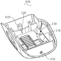
- Figure 2 is a schematic view showing the internal structure of the end cover of the embodiment of Figure 1;
- Figure 3 is a partially enlarged schematic view showing the top end of the main casing in the embodiment of Figure 1;
- FIG 4 is a schematic structural view of the fixing member in the embodiment of Figure 1;
- Figure 5 is a schematic view showing the structure disassembly of the second embodiment of the battery case of the present invention.
- Figure 6 is a partially enlarged plan view showing the top end of the main casing in the embodiment of Figure 5.
- FIG. 1 is a schematic structural diagram of a first embodiment of a battery case of the present invention.
- the battery case includes, but is not limited to, the following structural components: an end cover 100 and a main housing 200.
- the main housing 200 is for accommodating and fixing a battery (not shown), and the battery is disposed inside the main housing 200.
- the end cover 100 is disposed at one end of the main housing 200, and the end cover 100 and the main housing 200 are detachably connected by the connecting member 300.
- FIG. 2 is a schematic view showing the internal structure of the end cap in the embodiment of FIG. 1.
- FIG. 3 is a partially enlarged schematic view showing the top end of the main casing in the embodiment of FIG. 1.
- the connecting member The detachable connection between the end cap 100 and the main housing 200 is achieved by the auxiliary fixture 400.
- the first through holes 110 are disposed on the opposite side walls of the end cover 100.
- the main housing 200 is provided with a fixing plate 210 at one end of the end cover 100.
- the fixing plate 210 is disposed.
- a second through hole 211 is defined, and the connecting member 300 passes through the first through hole 110 and the second through hole 211 and cooperates with the threaded hole 410 on the auxiliary fixing member 400 to realize the end cover 100 and the main housing 200.
- the connector 300 in this embodiment may be a screw.
- the end cover 100 may further be provided with a first through hole 110 on one side wall or a plurality of side walls, correspondingly corresponding to the number and position of the second through hole 211 and the auxiliary fixing member 400.
- the connecting member 300 can also pass through the first through hole 110 and the second through hole 211 and cooperate with the threaded hole 410 on the auxiliary fixing member 400 to achieve a fixed connection between the end cover 100 and the main housing 200.
- the main housing 200 is further provided with a first limiting plate 220 at an end of the end cover 100 .
- the first limiting plate 220 is along the insertion direction of the connecting member 300 and the fixing plate 210 . Interposed and located on the inner side of the fixed plate 210, where "inside" means close
- the main casing 200 is provided with a center position side of the fixing plate 210 and the end surface of one side of the first limiting plate 220, that is, a side closer to the insertion end of the connecting member 300.
- a first limiting slot 201 is formed between the first limiting plate 220 and the fixing plate 210.
- the auxiliary fixing component 400 is mounted in the first limiting slot 201.
- the fixing plates 210 engaged with each of the first through holes 110 are two pieces, and the two fixing plates 210 are overlapped in the insertion direction of the connecting member 300, and the first limiting plate 220 and the fixing plate located on the inner side A first limit card slot 201 is formed between 210.
- “inside” herein also refers to the side of the center position near the end surface of the main casing 200 where the fixing plate 210 and the first limiting plate 220 are disposed, that is, the side closer to the insertion end of the connecting member 300.
- the first limiting plate 220 that cooperates with each of the first through holes 110 is also preferably two pieces, and the two first limiting plates 220 are arranged side by side in the vertical direction of the insertion direction of the connecting member 300. Further, one of the two first limiting plates 220 in the embodiment is connected to the fixing plate 210 through the connecting wall 202.
- FIG. 4 is a schematic structural view of the fixing member in the embodiment of FIG. 1.
- the limiting protrusion 420 is used for the connection.
- the top of the wall 202 is used to define the position of the fixture 400 within the first limit card slot 201.
- the two first limiting plates 220 and the inner fixing plate 210 can be connected by a connecting wall, and correspondingly, both sides of the auxiliary fixing member 400 are extended with a finite position, and With regard to this part of the technical features, those skilled in the art can select the design according to the actual needs, and will not be detailed here.
- the fixing plate 210 and the first limiting plate 220 in the embodiment of the present invention may be integrally formed with the end surface of the main casing 200 covered by the end cover 100, and in a direction perpendicular to the end surface. extend.
- a second limiting plate 120 is further disposed on the inner side of the end cover 100 , and the second limiting plate 120 is configured to be mounted when the end cover 100 is assembled with the main housing 200 .
- the first through hole 110 on the end cover 100 and the second through hole 211 on the fixing plate 210 are aligned in the mounting direction.
- the second limiting plate 120 can be disposed opposite to the first through hole 110 , and the second limiting plate 120 can be integrated with the inner sidewall of the end cover 100 .
- end cover 100 and the main housing 200 may also be respectively provided with the third limiting plate 130 and the fourth limiting plate 230, and the third limiting plate 130 and the fourth limiting plate 230 are covered by the end cover 100. When they are disposed on the main casing 200, they cooperate with each other, thereby preventing relative rotation of the end cover 100 and the main casing 200 about the connecting member 300.
- the third limiting plate 130 is provided with a second limiting slot 131.
- the free end (ie, the top end) of the fourth limiting plate 230 is inserted into the second In the limit card slot 131, the card positioning is achieved.
- it can also be configured as a structure of a limited position card slot on the fourth limiting plate 230, or other mutual matching structure, as long as the structure capable of preventing the relative rotation of the end cover 100 and the main casing 200 around the connecting member 300 can be satisfied. Yes, it is not listed here.
- FIG. 5 is a schematic exploded view of the second embodiment of the battery case of the present invention
- FIG. 6 is a partially enlarged schematic view of the top end of the main case of the embodiment of FIG.
- the connecting member 300 is no longer connected to the auxiliary fixing member, but the fixing plate 210 is directly provided with a threaded hole 212 for connecting through the side wall of the end cover 100.
- the first through hole 110 and the threaded hole 212 on the fixing plate 210 cooperate to realize the detachable connection between the end cover 100 and the main housing 200.
- the connector 300 in this embodiment is also preferably a screw.
- the fixing plates 210 that cooperate with each of the first through holes 110 are also two pieces, and the two pieces of fixing plates 210 are overlapped in the insertion direction of the connecting member 300.
- the fixing plate 210 in the embodiment of the present invention may be integrally formed with the end surface of the main casing 200 covered by the end cover 100 and extend in a direction perpendicular to the end surface. Since the auxiliary fixing member is no longer provided in the embodiment, it is no longer necessary to provide a structure such as the first limiting plate.
- the second limiting plate 120 can also be disposed on the inner side of the inner cover 100.
- the second limiting plate 120 is used to hold the top cover 100 on the top of the fixing plate 210 when the end cover 100 is fitted with the main housing 200.
- the first through hole 110 on the 100 and the threaded hole 212 in the fixing plate 210 are aligned in the mounting direction.
- the second limiting plate 120 can be disposed opposite to the first through hole 110 , and the second limiting plate 120 can be integrated with the inner sidewall of the end cover 100 .
- end cover 100 and the main housing 200 may also be respectively provided with a third limiting plate 130 and a fourth limiting plate 230 that cooperate with each other, and the third limiting plate 130 and the fourth limiting plate 230 are at the end cover 100. When they are placed on the main casing 200, they cooperate with each other, thereby preventing relative rotation of the end cover 100 and the main casing 200 about the connecting member 300.
- the third limiting plate 130 is provided with a second limiting slot 131.
- the free end (ie, the top end) of the fourth limiting plate 230 is inserted into the second In the limit card slot 131, the card positioning is achieved.
- it can also be configured as a structure of a limited position card slot on the fourth limiting plate 230, or other mutual matching structure, as long as the structure capable of preventing the relative rotation of the end cover 100 and the main casing 200 around the connecting member 300 can be satisfied. Yes, it is not listed here.
- the battery casing provided by the present invention can easily disassemble and replace the battery casing by designing a detachable battery casing structure with simple structure, which can meet the user's individual needs for the battery casing.
- an embodiment of the present invention further provides a drone, which may be a structure such as a rotor drone or a fixed-wing drone, and the drone includes a battery component for The machine is powered.
- the battery pack then includes the battery case in the above embodiment and a battery housed in the main case of the battery case.
- the structural features of other parts of the drone those skilled in the art will not repeat them here.
Landscapes
- Chemical & Material Sciences (AREA)
- Chemical Kinetics & Catalysis (AREA)
- Electrochemistry (AREA)
- General Chemical & Material Sciences (AREA)
- Engineering & Computer Science (AREA)
- Aviation & Aerospace Engineering (AREA)
- Battery Mounting, Suspending (AREA)
Abstract
一种无人机及其电池组件、电池外壳,该电池外壳包括主壳体(200)以及端盖(100);主壳体(200)用于容置并固定电池,端盖(100)盖设于主壳体(200)一端,端盖(100)与主壳体(200)之间通过连接件(300)可拆卸连接。相对于现有技术,该无人机及其电池组件、电池外壳,通过设计结构简单的可拆卸的电池壳结构,方便对电池外壳进行拆卸和更换,可满足用户对电池外壳的个性需求。
Description
本发明涉及无人机电池结构的技术领域,特别涉及一种无人机及其电池组件、电池外壳。
电池外壳作为电池的一种固定和保护结构,现有技术中的电池外壳的各部分(一般是端盖与主体部)之间一般采用卡扣加胶水的配合连接形式。
具体地,通过电池壳端盖上的卡接凸起与电池壳主体部上开设的卡槽配合卡接,然后再利用胶水在连接部位进行粘接。很显然,这种连接形式配合为不可更换的结构形式,即使不使用胶水粘接,卡接凸起与卡槽的配合也是较难拆卸的结构形式。
这种结构形式对一些喜欢自己DIY以及不同颜色整机需要安装同一块电池的情况而言,是很不方便的而且很受限的一种结构连接设计方式。
发明内容
本发明提供一种无人机及其电池组件、电池外壳,能够解决现有技术中电池壳拆卸不便的技术问题。
为解决上述问题,本发明提供一种电池外壳,所述电池外壳包括主壳体以及端盖;所述主壳体用于容置并固定电池,所述端盖盖设于所述主壳体一端,所述端盖与所述主壳体之间通过连接件可拆卸连接。
根据本发明一优选实施例,所述端盖的至少一个侧壁上设有第一通孔,所述主壳体在所述端盖所盖设的一端设有固定板,所述固定板上设有螺纹孔,所述连接件用于穿过所述端盖侧壁上的第一通孔并与所述固
定板上的螺纹孔配合,进而实现所述端盖与所述主壳体之间的可拆卸连接。
根据本发明一优选实施例,所述端盖的至少一个侧壁上设有第一通孔,所述主壳体在所述端盖所盖设的一端设有固定板,所述固定板上设有第二通孔,所述连接件用于穿过所述第一通孔和所述第二通孔并通过与辅助固定件上的螺纹孔配合,实现所述端盖与所述主壳体之间的固定连接。
根据本发明一优选实施例,所述主壳体在所述端盖所盖设的一端设有第一限位卡槽,所述辅助固定件安装于所述第一限位卡槽内。
根据本发明一优选实施例,所述主壳体在所述端盖所盖设的一端设有第一限位板,所述第一限位板沿所述连接件的插入方向与所述固定板间隔设置且位于所述固定板的内侧,进而在所述第一限位板与所述固定板之间形成所述第一限位卡槽。
根据本发明一优选实施例,与所述第一通孔配合的固定板为两片,所述两片固定板沿所述连接件的插入方向叠合设置,所述第一限位板与位于内侧的固定板之间形成所述第一限位卡槽。
根据本发明一优选实施例,所述第一限位板为两片,所述两片第一限位板在所述连接件的插入方向的垂直方向上并排设置。
根据本发明一优选实施例,至少一片所述第一限位板与所述固定板之间通过连接壁连接;所述辅助固定件的至少一侧边延伸设置有限位凸起,所述限位凸起用于卡设在所述连接壁的顶部。
根据本发明一优选实施例,所述端盖内侧顶部设有第二限位板,所述第二限位板用于在所述端盖与所述主壳体配合安装时,顶持在所述固定板的顶部,进而使所述端盖上的第一通孔和所述固定板上的螺纹孔或第二通孔在安装方向上位置对准。
根据本发明一优选实施例,所述连接件为螺钉。
根据本发明一优选实施例,所述端盖在相对的两个侧壁上分别设有所述第一通孔,所述主壳体在所述端盖所盖设的一端分别设有与所述第一通孔配合的固定板,进而从所述端盖的相对两侧与所述主壳体之间进
行可拆卸连接。
根据本发明一优选实施例,所述端盖和所述主壳体分别设置有彼此配合第三限位板和第四限位板,所述第三限位板和第四限位板在所述端盖盖设于所述主壳体上时彼此配合,进而防止所述端盖和所述主壳体绕所述连接件的相对转动。
根据本发明一优选实施例,所述第三限位板和第四限位板中的一个上设置有第二限位卡槽,在所述端盖盖设于所述主壳体上时,所述第三限位板和第四限位板中的另一个的自由端插入所述第二限位卡槽。
为解决上述技术问题,本发明还提供一种电池组件,所述电池组件包括上述实施例中任一项所述的电池外壳以及容置于所述电池外壳的主壳体内的电池。
进一步地,本发明又提供一种无人机,所述无人机包括上述实施例中所述的电池组件。
相对于现有技术,本发明提供的无人机及其电池组件、电池外壳,通过设计结构简单的可拆卸的电池壳结构,方便对电池外壳进行拆卸和更换,可满足用户对电池外壳的个性需求。
为了更清楚地说明本发明实施例中的技术方案,下面将对实施例描述中所需要使用的附图作简单地介绍,显而易见地,下面描述中的附图仅仅是本发明的一些实施例,对于本领域普通技术人员来讲,在不付出创造性劳动的前提下,还可以根据这些附图获得其他的附图。
图1是本发明电池外壳第一实施例的结构拆解示意图;
图2是图1实施例中端盖的内部结构示意图;
图3是图1实施例中主壳体顶端的局部放大示意图;
图4是图1实施例中固定件的结构示意图;
图5是本发明电池外壳第二实施例的结构拆解示意图;以及
图6是图5实施例中主壳体顶端的局部放大示意图。
下面将结合本发明实施例中的附图,对本发明实施例中的技术方案进行清楚、完整地描述,显然,所描述的实施例仅是本发明的一部分实施例,而不是全部的实施例。基于本发明中的实施例,本领域普通技术人员在没有做出创造性劳动前提下所获得的所有其他实施例,都属于本发明保护的范围。
电池外壳实施例1
请参阅图1,图1是本发明电池外壳第一实施例的结构拆解示意图,该电池外壳包括但不限于以下结构组成:端盖100以及主壳体200。其中,主壳体200用于容置并固定电池(图中未示),电池设于主壳体200的内部。端盖100盖设于主壳体200的一端,端盖100与主壳体200之间通过连接件300可拆卸连接。
请一并参阅图2和图3,图2是图1实施例中端盖的内部结构示意图,图3是图1实施例中主壳体顶端的局部放大示意图,在本实施例中,连接件300通过辅助固定件400实现端盖100与主壳体200之间可拆卸连接。
具体而言,本实施例中端盖100的相对两个侧壁上设有第一通孔110;而主壳体200在端盖100所盖设的一端相应设有固定板210,固定板210上设有第二通孔211,连接件300穿过第一通孔110和第二通孔211并通过与辅助固定件400上的螺纹孔410配合,实现端盖100与主壳体200之间的固定连接。优选地,本实施例中的连接件300可以为螺钉。
另外,在其他实施例中,端盖100的还可以为在一个侧壁或者多个侧壁上设置第一通孔110,相应的设置对应数量和位置的第二通孔211以及辅助固定件400,连接件300同样可以为穿过第一通孔110和第二通孔211并通过与辅助固定件400上的螺纹孔410配合,实现端盖100与主壳体200之间的固定连接,这部分技术特征在本领域技术人员的理解范围内,此处不再赘述。
优选地,请继续参阅图3,主壳体200在端盖100所盖设的一端还设有第一限位板220,该第一限位板220沿连接件300的插入方向与固定板210间隔设置且位于固定板210的内侧,此处的“内侧”是指靠近
主壳体200设置固定板210和第一限位板220一侧端面的中心位置一侧,也即更靠近连接件300插入端的一侧。该第一限位板220与固定板210之间形成第一限位卡槽201,辅助固定件400安装于该第一限位卡槽201内。
进一步优选地,与每一个第一通孔110配合的固定板210均为两片,两片固定板210沿连接件300的插入方向叠合设置,第一限位板220与位于内侧的固定板210之间形成第一限位卡槽201。同样的,此处的“内侧”也是指靠近主壳体200设置固定板210和第一限位板220一侧端面的中心位置一侧,也即更靠近连接件300插入端的一侧。
而与每一个第一通孔110配合的第一限位板220也优选为两片,两片第一限位板220在连接件300插入方向的垂直方向上并排设置。进一步地,本实施例中的两片第一限位板220中的一片与固定板210之间通过连接壁202连接。
相应的,辅助固定件400的一侧边延伸设置有限位凸起420,请参阅图4,图4是图1实施例中固定件的结构示意图,该限位凸起420用于卡设在连接壁202的顶部,用以限定固定件400在第一限位卡槽201内的位置。当然,在其他实施例中,两片第一限位板220与内侧固定板210之间均可以通过连接壁连接,相应的,辅助固定件400的两侧边延伸均设置有限位凸起,而关于这部分技术特征,在本发明的启发下,本领域技术人员可以根据实际需求自行选取设计,此处亦不再详述。
需要说明的是,本发明实施例中的固定板210以及第一限位板220均可以为与主壳体200在端盖100所盖设的端面一体结构设置,且沿垂直于该端面的方向延伸。
进一步优选地,请继续参阅图2,该端盖100内侧顶部还设有第二限位板120,该第二限位板120用于在端盖100与主壳体200配合安装时,顶持在固定板210的顶部,进而使端盖100上的第一通孔110和固定板210上的第二通孔211在安装方向上位置对准。其中,该第二限位板120可以与第一通孔110正对设置,且该第二限位板120可以与端盖100的内侧壁为一体结构。
进一步地,端盖100和主壳体200还可以分别设置有彼此配合第三限位板130和第四限位板230,第三限位板130和第四限位板230在端盖100盖设于主壳体200上时彼此配合,进而防止端盖100和主壳体200绕连接件300的相对转动。
具体地,第三限位板130上设置有第二限位卡槽131,在端盖100盖设于主壳体200上时,第四限位板230的自由端(即顶端)插入第二限位卡槽131内,实现卡接定位。当然,也可以设置为第四限位板230上有限位卡槽的结构形式,或者其他的彼此配合结构,只要能满足可以防止端盖100和主壳体200绕连接件300的相对转动的结构均可,此处不再一一列举。
电池外壳实施例2
请一并参阅图2以及图5和图6,图5是本发明电池外壳第二实施例的结构拆解示意图,图6是图5实施例中主壳体顶端的局部放大示意图。与上一实施例不同的是,该实施例中连接件300不再与辅助固定件连接,而是固定板210上直接设有螺纹孔212,连接件300用于穿过端盖100侧壁上的第一通孔110并与固定板210上的螺纹孔212配合,即可实现端盖100与主壳体200之间的可拆卸连接。同样的,本实施例中的连接件300也优选为螺钉。
本实施例中与每一个第一通孔110配合的固定板210也均为两片,两片固定板210沿连接件300的插入方向叠合设置。同样的,本发明实施例中的固定板210可以为与主壳体200在端盖100所盖设的端面一体结构设置,且沿垂直于该端面的方向延伸。由于本实施例中不再设置辅助固定件,因此也不再需要设置第一限位板等结构。
端盖100内侧顶部同样可以设有第二限位板120,第二限位板120用于在端盖100与主壳体200配合安装时,顶持在固定板210的顶部,进而使端盖100上的第一通孔110和固定板210上的螺纹孔212在安装方向上位置对准。其中,该第二限位板120可以与第一通孔110正对设置,且该第二限位板120可以与端盖100的内侧壁为一体结构。
进一步地,端盖100和主壳体200也可以分别设置有彼此配合的第三限位板130和第四限位板230,第三限位板130和第四限位板230在端盖100盖设于主壳体200上时彼此配合,进而防止端盖100和主壳体200绕连接件300的相对转动。
具体地,第三限位板130上设置有第二限位卡槽131,在端盖100盖设于主壳体200上时,第四限位板230的自由端(即顶端)插入第二限位卡槽131内,实现卡接定位。当然,也可以设置为第四限位板230上有限位卡槽的结构形式,或者其他的彼此配合结构,只要能满足可以防止端盖100和主壳体200绕连接件300的相对转动的结构均可,此处不再一一列举。
相对于现有技术,本发明提供的电池外壳,通过设计结构简单的可拆卸电池壳结构,方便对电池外壳进行拆卸和更换,可满足用户对电池外壳的个性需求。
另外,本发明实施例还提供一种无人机,该无人机可以为旋翼无人机或者固定翼无人机等结构,该无人机包括一电池组件,该电池组件用于对无人机进行供电。电池组件则包括上述实施例中的电池外壳以及容置于电池外壳的主壳体内的电池。关于无人机其他部分的结构特征,在本领域技术人员的理解范围内,此处不再赘述。
以上所述仅为本发明的部分实施例,并非因此限制本发明的保护范围,凡是利用本发明说明书及附图内容所作的等效装置或等效流程变换,或直接或间接运用在其他相关的技术领域,均同理包括在本发明的专利保护范围内。
Claims (15)
- 一种电池外壳,其特征在于,所述电池外壳包括主壳体以及端盖;所述主壳体用于容置并固定电池,所述端盖盖设于所述主壳体一端,所述端盖与所述主壳体之间通过连接件可拆卸连接。
- 根据权利要求1所述的电池外壳,其特征在于,所述端盖的至少一个侧壁上设有第一通孔,所述主壳体在所述端盖所盖设的一端设有固定板,所述固定板上设有螺纹孔,所述连接件用于穿过所述端盖侧壁上的第一通孔并与所述固定板上的螺纹孔配合,进而实现所述端盖与所述主壳体之间的可拆卸连接。
- 根据权利要求1所述的电池外壳,其特征在于,所述端盖的至少一个侧壁上设有第一通孔,所述主壳体在所述端盖所盖设的一端设有固定板,所述固定板上设有第二通孔,所述连接件用于穿过所述第一通孔和所述第二通孔并通过与辅助固定件上的螺纹孔配合,实现所述端盖与所述主壳体之间的固定连接。
- 根据权利要求3所述的电池外壳,其特征在于,所述主壳体在所述端盖所盖设的一端设有第一限位卡槽,所述辅助固定件安装于所述第一限位卡槽内。
- 根据权利要求4所述的电池外壳,其特征在于,所述主壳体在所述端盖所盖设的一端设有第一限位板,所述第一限位板沿所述连接件的插入方向与所述固定板间隔设置且位于所述固定板的内侧,进而在所述第一限位板与所述固定板之间形成所述第一限位卡槽。
- 根据权利要求5所述的电池外壳,其特征在于,与所述第一通孔配合的固定板为两片,所述两片固定板沿所述连接件的插入方向叠合设置,所述第一限位板与位于内侧的固定板之间形成所述第一限位卡槽。
- 根据权利要求5所述的电池外壳,其特征在于,所述第一限位板为两片,所述两片第一限位板在所述连接件的插入方向的垂直方向上并排设置。
- 根据权利要求7所述的电池外壳,其特征在于,至少一片所述第一限位板与所述固定板之间通过连接壁连接;所述辅助固定件的至少一侧边延伸设置有限位凸起,所述限位凸起用于卡设在所述连接壁的顶部。
- 根据权利要求2-8任一项所述的电池外壳,其特征在于,所述端盖内侧顶部设有第二限位板,所述第二限位板用于在所述端盖与所述主壳体配合安装时,顶持在所述固定板的顶部,进而使所述端盖上的第一通孔和所述固定板上的螺纹孔或第二通孔在安装方向上位置对准。
- 根据权利要求2-8任一项所述的电池外壳,其特征在于,所述连接件为螺钉。
- 根据权利要求2-8任一项所述的电池外壳,其特征在于,所述端盖在相对的两个侧壁上分别设有所述第一通孔,所述主壳体在所述端盖所盖设的一端分别设有与所述第一通孔配合的固定板,进而从所述端盖的相对两侧与所述主壳体之间进行可拆卸连接。
- 根据权利要求2-8任一项所述的电池外壳,其特征在于,所述端盖和所述主壳体分别设置有彼此配合第三限位板和第四限位板,所述第三限位板和第四限位板在所述端盖盖设于所述主壳体上时彼此配合,进而防止所述端盖和所述主壳体绕所述连接件的相对转动。
- 根据权利要求12所述的电池外壳,其特征在于,所述第三限位板和第四限位板中的一个上设置有第二限位卡槽,在所述端盖盖设于所述主壳体上时,所述第三限位板和第四限位板中的另一个的自由端插入所述第二限位卡槽。
- 一种电池组件,其特征在于,所述电池组件包括权利要求1-13任一项所述的电池外壳以及容置于所述电池外壳的主壳体内的电池。
- 一种无人机,其特征在于,所述无人机包括权利要求14所述的电池组件。
Priority Applications (1)
| Application Number | Priority Date | Filing Date | Title |
|---|---|---|---|
| CN201680088838.8A CN109643774B (zh) | 2016-10-27 | 2016-12-08 | 无人机及其电池组件、电池外壳 |
Applications Claiming Priority (2)
| Application Number | Priority Date | Filing Date | Title |
|---|---|---|---|
| CN201621182419.4U CN206401391U (zh) | 2016-10-27 | 2016-10-27 | 无人机及其电池组件、电池外壳 |
| CN201621182419.4 | 2016-10-27 |
Publications (1)
| Publication Number | Publication Date |
|---|---|
| WO2018076469A1 true WO2018076469A1 (zh) | 2018-05-03 |
Family
ID=59506842
Family Applications (1)
| Application Number | Title | Priority Date | Filing Date |
|---|---|---|---|
| PCT/CN2016/109002 Ceased WO2018076469A1 (zh) | 2016-10-27 | 2016-12-08 | 无人机及其电池组件、电池外壳 |
Country Status (2)
| Country | Link |
|---|---|
| CN (2) | CN206401391U (zh) |
| WO (1) | WO2018076469A1 (zh) |
Cited By (2)
| Publication number | Priority date | Publication date | Assignee | Title |
|---|---|---|---|---|
| CN112896497A (zh) * | 2021-03-23 | 2021-06-04 | 珠海紫燕无人飞行器有限公司 | 一种无人直升机 |
| CN114784413A (zh) * | 2022-04-26 | 2022-07-22 | 深圳市思肯三维科技发展有限公司 | 一种用于手持移动式美肤仪的电池模块 |
Families Citing this family (1)
| Publication number | Priority date | Publication date | Assignee | Title |
|---|---|---|---|---|
| CN206401391U (zh) * | 2016-10-27 | 2017-08-11 | 深圳市大疆创新科技有限公司 | 无人机及其电池组件、电池外壳 |
Citations (6)
| Publication number | Priority date | Publication date | Assignee | Title |
|---|---|---|---|---|
| US20080266764A1 (en) * | 2007-04-30 | 2008-10-30 | Asustek Computer Inc. | Casing and mobile communication apparatus |
| CN204333074U (zh) * | 2014-12-30 | 2015-05-13 | 河南鸿马实业有限公司 | 一种电动汽车的电池箱 |
| CN105449138A (zh) * | 2015-12-28 | 2016-03-30 | 天津力神特种电源科技股份公司 | 一种圆柱形锂离子电池组的外壳 |
| CN205231145U (zh) * | 2015-12-28 | 2016-05-11 | 天津力神特种电源科技股份公司 | 一种圆柱形锂离子电池组的外壳 |
| CN205542983U (zh) * | 2016-04-12 | 2016-08-31 | 洛阳鑫光锂电科技有限公司 | 一种动力电池箱 |
| CN106031318A (zh) * | 2015-09-08 | 2016-10-12 | 深圳市大疆创新科技有限公司 | 移动装置及其电池模组和锁定装置 |
Family Cites Families (6)
| Publication number | Priority date | Publication date | Assignee | Title |
|---|---|---|---|---|
| JP2005203698A (ja) * | 2004-01-19 | 2005-07-28 | Hitachi Communication Technologies Ltd | 電気機器の筐体構造 |
| CN200983709Y (zh) * | 2006-12-21 | 2007-11-28 | 刘齐璋 | 一种电子镇流器外壳 |
| CN203871949U (zh) * | 2014-03-19 | 2014-10-08 | 常州市长昊机械有限公司 | 方便安装的电机外壳 |
| CN104902706A (zh) * | 2015-06-08 | 2015-09-09 | 廖婕 | 一种高精度装配壳体 |
| CN106058114B (zh) * | 2016-08-15 | 2018-08-21 | 贵州众智达系统新能源股份有限公司 | 一种高密封性的电池包箱体 |
| CN206401391U (zh) * | 2016-10-27 | 2017-08-11 | 深圳市大疆创新科技有限公司 | 无人机及其电池组件、电池外壳 |
-
2016
- 2016-10-27 CN CN201621182419.4U patent/CN206401391U/zh not_active Expired - Fee Related
- 2016-12-08 WO PCT/CN2016/109002 patent/WO2018076469A1/zh not_active Ceased
- 2016-12-08 CN CN201680088838.8A patent/CN109643774B/zh not_active Expired - Fee Related
Patent Citations (6)
| Publication number | Priority date | Publication date | Assignee | Title |
|---|---|---|---|---|
| US20080266764A1 (en) * | 2007-04-30 | 2008-10-30 | Asustek Computer Inc. | Casing and mobile communication apparatus |
| CN204333074U (zh) * | 2014-12-30 | 2015-05-13 | 河南鸿马实业有限公司 | 一种电动汽车的电池箱 |
| CN106031318A (zh) * | 2015-09-08 | 2016-10-12 | 深圳市大疆创新科技有限公司 | 移动装置及其电池模组和锁定装置 |
| CN105449138A (zh) * | 2015-12-28 | 2016-03-30 | 天津力神特种电源科技股份公司 | 一种圆柱形锂离子电池组的外壳 |
| CN205231145U (zh) * | 2015-12-28 | 2016-05-11 | 天津力神特种电源科技股份公司 | 一种圆柱形锂离子电池组的外壳 |
| CN205542983U (zh) * | 2016-04-12 | 2016-08-31 | 洛阳鑫光锂电科技有限公司 | 一种动力电池箱 |
Cited By (3)
| Publication number | Priority date | Publication date | Assignee | Title |
|---|---|---|---|---|
| CN112896497A (zh) * | 2021-03-23 | 2021-06-04 | 珠海紫燕无人飞行器有限公司 | 一种无人直升机 |
| CN114784413A (zh) * | 2022-04-26 | 2022-07-22 | 深圳市思肯三维科技发展有限公司 | 一种用于手持移动式美肤仪的电池模块 |
| CN114784413B (zh) * | 2022-04-26 | 2023-01-31 | 深圳市思肯三维科技发展有限公司 | 一种用于手持移动式美肤仪的电池模块 |
Also Published As
| Publication number | Publication date |
|---|---|
| CN109643774A (zh) | 2019-04-16 |
| CN109643774B (zh) | 2021-12-07 |
| CN206401391U (zh) | 2017-08-11 |
Similar Documents
| Publication | Publication Date | Title |
|---|---|---|
| CN111133607B (zh) | 电源装置 | |
| WO2018076469A1 (zh) | 无人机及其电池组件、电池外壳 | |
| TWI546007B (zh) | 電子裝置 | |
| CN101315512A (zh) | 色轮组件及色轮 | |
| TWI485955B (zh) | 音圈馬達 | |
| US20120120620A1 (en) | Waterproof element and electronic device having the waterproof element | |
| TW201517741A (zh) | 電路板固定結構 | |
| CN111164784B (zh) | 电源装置 | |
| CN207441824U (zh) | 电池包壳体 | |
| WO2017206434A1 (zh) | 保护壳、电子装置、电子调速器及无人机 | |
| TWM520409U (zh) | 過濾裝置 | |
| JP2014010157A (ja) | 光ループバックコネクタ | |
| WO2019019677A1 (zh) | 箱子 | |
| WO2013073108A1 (ja) | 携帯端末 | |
| CN215411082U (zh) | 拆装组件和安装装置 | |
| TW201426118A (zh) | 顯示裝置 | |
| CN204787561U (zh) | 一种用于冰箱的箱壳内部拐角处的拐角紧固件 | |
| TWM558301U (zh) | 可拆卸風扇模組 | |
| JP2014155362A (ja) | 電気接続箱及び電気接続箱の組立方法 | |
| JP5719962B1 (ja) | 結合具および容器 | |
| CN223942518U (zh) | 一种电动折叠器的电机防护外壳结构 | |
| CN216123313U (zh) | 散热扇固定结构、散热扇组件及电子设备 | |
| CN108082469A (zh) | 螺旋桨、螺旋桨组件及无人机 | |
| KR200482662Y1 (ko) | 실외 전등의 소켓 결합구조 | |
| KR200476142Y1 (ko) | 커튼용 구동 조립체 |
Legal Events
| Date | Code | Title | Description |
|---|---|---|---|
| 121 | Ep: the epo has been informed by wipo that ep was designated in this application |
Ref document number: 16919966 Country of ref document: EP Kind code of ref document: A1 |
|
| NENP | Non-entry into the national phase |
Ref country code: DE |
|
| 122 | Ep: pct application non-entry in european phase |
Ref document number: 16919966 Country of ref document: EP Kind code of ref document: A1 |