WO2018074833A1 - 다중 파장 내시경 시스템 및 이를 이용한 영상 처리 방법 - Google Patents
다중 파장 내시경 시스템 및 이를 이용한 영상 처리 방법 Download PDFInfo
- Publication number
- WO2018074833A1 WO2018074833A1 PCT/KR2017/011522 KR2017011522W WO2018074833A1 WO 2018074833 A1 WO2018074833 A1 WO 2018074833A1 KR 2017011522 W KR2017011522 W KR 2017011522W WO 2018074833 A1 WO2018074833 A1 WO 2018074833A1
- Authority
- WO
- WIPO (PCT)
- Prior art keywords
- image data
- light
- wavelength
- fluorescent materials
- fluorescent
- Prior art date
- Legal status (The legal status is an assumption and is not a legal conclusion. Google has not performed a legal analysis and makes no representation as to the accuracy of the status listed.)
- Ceased
Links
Images




Classifications
-
- A—HUMAN NECESSITIES
- A61—MEDICAL OR VETERINARY SCIENCE; HYGIENE
- A61B—DIAGNOSIS; SURGERY; IDENTIFICATION
- A61B1/00—Instruments for performing medical examinations of the interior of cavities or tubes of the body by visual or photographical inspection, e.g. endoscopes; Illuminating arrangements therefor
- A61B1/06—Instruments for performing medical examinations of the interior of cavities or tubes of the body by visual or photographical inspection, e.g. endoscopes; Illuminating arrangements therefor with illuminating arrangements
-
- A—HUMAN NECESSITIES
- A61—MEDICAL OR VETERINARY SCIENCE; HYGIENE
- A61B—DIAGNOSIS; SURGERY; IDENTIFICATION
- A61B1/00—Instruments for performing medical examinations of the interior of cavities or tubes of the body by visual or photographical inspection, e.g. endoscopes; Illuminating arrangements therefor
- A61B1/06—Instruments for performing medical examinations of the interior of cavities or tubes of the body by visual or photographical inspection, e.g. endoscopes; Illuminating arrangements therefor with illuminating arrangements
- A61B1/0638—Instruments for performing medical examinations of the interior of cavities or tubes of the body by visual or photographical inspection, e.g. endoscopes; Illuminating arrangements therefor with illuminating arrangements providing two or more wavelengths
-
- A—HUMAN NECESSITIES
- A61—MEDICAL OR VETERINARY SCIENCE; HYGIENE
- A61B—DIAGNOSIS; SURGERY; IDENTIFICATION
- A61B1/00—Instruments for performing medical examinations of the interior of cavities or tubes of the body by visual or photographical inspection, e.g. endoscopes; Illuminating arrangements therefor
-
- A—HUMAN NECESSITIES
- A61—MEDICAL OR VETERINARY SCIENCE; HYGIENE
- A61B—DIAGNOSIS; SURGERY; IDENTIFICATION
- A61B1/00—Instruments for performing medical examinations of the interior of cavities or tubes of the body by visual or photographical inspection, e.g. endoscopes; Illuminating arrangements therefor
- A61B1/00002—Operational features of endoscopes
- A61B1/00004—Operational features of endoscopes characterised by electronic signal processing
- A61B1/00009—Operational features of endoscopes characterised by electronic signal processing of image signals during a use of endoscope
-
- A—HUMAN NECESSITIES
- A61—MEDICAL OR VETERINARY SCIENCE; HYGIENE
- A61B—DIAGNOSIS; SURGERY; IDENTIFICATION
- A61B1/00—Instruments for performing medical examinations of the interior of cavities or tubes of the body by visual or photographical inspection, e.g. endoscopes; Illuminating arrangements therefor
- A61B1/00163—Optical arrangements
- A61B1/00186—Optical arrangements with imaging filters
-
- A—HUMAN NECESSITIES
- A61—MEDICAL OR VETERINARY SCIENCE; HYGIENE
- A61B—DIAGNOSIS; SURGERY; IDENTIFICATION
- A61B1/00—Instruments for performing medical examinations of the interior of cavities or tubes of the body by visual or photographical inspection, e.g. endoscopes; Illuminating arrangements therefor
- A61B1/04—Instruments for performing medical examinations of the interior of cavities or tubes of the body by visual or photographical inspection, e.g. endoscopes; Illuminating arrangements therefor combined with photographic or television appliances
-
- A—HUMAN NECESSITIES
- A61—MEDICAL OR VETERINARY SCIENCE; HYGIENE
- A61B—DIAGNOSIS; SURGERY; IDENTIFICATION
- A61B1/00—Instruments for performing medical examinations of the interior of cavities or tubes of the body by visual or photographical inspection, e.g. endoscopes; Illuminating arrangements therefor
- A61B1/04—Instruments for performing medical examinations of the interior of cavities or tubes of the body by visual or photographical inspection, e.g. endoscopes; Illuminating arrangements therefor combined with photographic or television appliances
- A61B1/042—Instruments for performing medical examinations of the interior of cavities or tubes of the body by visual or photographical inspection, e.g. endoscopes; Illuminating arrangements therefor combined with photographic or television appliances characterised by a proximal camera, e.g. a CCD camera
-
- A—HUMAN NECESSITIES
- A61—MEDICAL OR VETERINARY SCIENCE; HYGIENE
- A61B—DIAGNOSIS; SURGERY; IDENTIFICATION
- A61B1/00—Instruments for performing medical examinations of the interior of cavities or tubes of the body by visual or photographical inspection, e.g. endoscopes; Illuminating arrangements therefor
- A61B1/04—Instruments for performing medical examinations of the interior of cavities or tubes of the body by visual or photographical inspection, e.g. endoscopes; Illuminating arrangements therefor combined with photographic or television appliances
- A61B1/043—Instruments for performing medical examinations of the interior of cavities or tubes of the body by visual or photographical inspection, e.g. endoscopes; Illuminating arrangements therefor combined with photographic or television appliances for fluorescence imaging
-
- A—HUMAN NECESSITIES
- A61—MEDICAL OR VETERINARY SCIENCE; HYGIENE
- A61B—DIAGNOSIS; SURGERY; IDENTIFICATION
- A61B1/00—Instruments for performing medical examinations of the interior of cavities or tubes of the body by visual or photographical inspection, e.g. endoscopes; Illuminating arrangements therefor
- A61B1/06—Instruments for performing medical examinations of the interior of cavities or tubes of the body by visual or photographical inspection, e.g. endoscopes; Illuminating arrangements therefor with illuminating arrangements
- A61B1/0661—Endoscope light sources
-
- A—HUMAN NECESSITIES
- A61—MEDICAL OR VETERINARY SCIENCE; HYGIENE
- A61B—DIAGNOSIS; SURGERY; IDENTIFICATION
- A61B1/00—Instruments for performing medical examinations of the interior of cavities or tubes of the body by visual or photographical inspection, e.g. endoscopes; Illuminating arrangements therefor
- A61B1/31—Instruments for performing medical examinations of the interior of cavities or tubes of the body by visual or photographical inspection, e.g. endoscopes; Illuminating arrangements therefor for the rectum, e.g. proctoscopes, sigmoidoscopes, colonoscopes
-
- A—HUMAN NECESSITIES
- A61—MEDICAL OR VETERINARY SCIENCE; HYGIENE
- A61B—DIAGNOSIS; SURGERY; IDENTIFICATION
- A61B5/00—Measuring for diagnostic purposes; Identification of persons
- A61B5/0033—Features or image-related aspects of imaging apparatus, e.g. for MRI, optical tomography or impedance tomography apparatus; Arrangements of imaging apparatus in a room
- A61B5/0036—Features or image-related aspects of imaging apparatus, e.g. for MRI, optical tomography or impedance tomography apparatus; Arrangements of imaging apparatus in a room including treatment, e.g., using an implantable medical device, ablating, ventilating
-
- A—HUMAN NECESSITIES
- A61—MEDICAL OR VETERINARY SCIENCE; HYGIENE
- A61B—DIAGNOSIS; SURGERY; IDENTIFICATION
- A61B5/00—Measuring for diagnostic purposes; Identification of persons
- A61B5/0059—Measuring for diagnostic purposes; Identification of persons using light, e.g. diagnosis by transillumination, diascopy, fluorescence
- A61B5/0071—Measuring for diagnostic purposes; Identification of persons using light, e.g. diagnosis by transillumination, diascopy, fluorescence by measuring fluorescence emission
-
- A—HUMAN NECESSITIES
- A61—MEDICAL OR VETERINARY SCIENCE; HYGIENE
- A61B—DIAGNOSIS; SURGERY; IDENTIFICATION
- A61B5/00—Measuring for diagnostic purposes; Identification of persons
- A61B5/0059—Measuring for diagnostic purposes; Identification of persons using light, e.g. diagnosis by transillumination, diascopy, fluorescence
- A61B5/0075—Measuring for diagnostic purposes; Identification of persons using light, e.g. diagnosis by transillumination, diascopy, fluorescence by spectroscopy, i.e. measuring spectra, e.g. Raman spectroscopy, infrared absorption spectroscopy
-
- A—HUMAN NECESSITIES
- A61—MEDICAL OR VETERINARY SCIENCE; HYGIENE
- A61B—DIAGNOSIS; SURGERY; IDENTIFICATION
- A61B5/00—Measuring for diagnostic purposes; Identification of persons
- A61B5/0059—Measuring for diagnostic purposes; Identification of persons using light, e.g. diagnosis by transillumination, diascopy, fluorescence
- A61B5/0082—Measuring for diagnostic purposes; Identification of persons using light, e.g. diagnosis by transillumination, diascopy, fluorescence adapted for particular medical purposes
- A61B5/0084—Measuring for diagnostic purposes; Identification of persons using light, e.g. diagnosis by transillumination, diascopy, fluorescence adapted for particular medical purposes for introduction into the body, e.g. by catheters
-
- G—PHYSICS
- G01—MEASURING; TESTING
- G01N—INVESTIGATING OR ANALYSING MATERIALS BY DETERMINING THEIR CHEMICAL OR PHYSICAL PROPERTIES
- G01N21/00—Investigating or analysing materials by the use of optical means, i.e. using sub-millimetre waves, infrared, visible or ultraviolet light
- G01N21/62—Systems in which the material investigated is excited whereby it emits light or causes a change in wavelength of the incident light
- G01N21/63—Systems in which the material investigated is excited whereby it emits light or causes a change in wavelength of the incident light optically excited
- G01N21/64—Fluorescence; Phosphorescence
- G01N21/645—Specially adapted constructive features of fluorimeters
- G01N21/6456—Spatial resolved fluorescence measurements; Imaging
-
- G—PHYSICS
- G01—MEASURING; TESTING
- G01N—INVESTIGATING OR ANALYSING MATERIALS BY DETERMINING THEIR CHEMICAL OR PHYSICAL PROPERTIES
- G01N21/00—Investigating or analysing materials by the use of optical means, i.e. using sub-millimetre waves, infrared, visible or ultraviolet light
- G01N21/62—Systems in which the material investigated is excited whereby it emits light or causes a change in wavelength of the incident light
- G01N21/63—Systems in which the material investigated is excited whereby it emits light or causes a change in wavelength of the incident light optically excited
- G01N21/64—Fluorescence; Phosphorescence
- G01N2021/6417—Spectrofluorimetric devices
- G01N2021/6421—Measuring at two or more wavelengths
Definitions
- the present invention relates to a multi-wavelength endoscope system and an image processing method using the same.
- the probability of detection is further lowered.
- the Goetz group has developed a probe that can identify the Epidermal Growth Factor Receptor (EGFR), and attempts to image it using a special endoscope called Confocal Endomicroscopy.
- EGFR Epidermal Growth Factor Receptor
- An object of the present invention is to provide a multi-wavelength endoscope system and an image processing method using the same, which can provide image diagnosis by processing image data photographing a labeled observation site using a plurality of probes for a complex target. will be.
- a multi-wavelength endoscope system for photographing an observation part labeled with a plurality of fluorescent materials having different colors may include incident light reflected from the observation part in a first direction and a second perpendicular to the first direction.
- a polarization direction a photographing unit for dividing the spectral regions polarized in the first direction and the second direction into a plurality of spectral channels, and measuring image intensity of each of the plurality of spectral channels to obtain image data;
- the photographing unit is a beam splitter that polarizes the incident light in the first direction and the second direction perpendicular to the first direction, and is positioned in a path of light separated in the first direction and passes a light having a predetermined range.
- the computing unit may store the unprocessed fluorescence spectrum extracted from the unprocessed image data obtained by photographing the observation portion that does not process the fluorescence material.
- the computing unit may perform a correction to remove the self-fluorescence component included in the image data photographed by the photographing unit by using the unprocessed fluorescence spectrum.
- a multi-wavelength endoscope system for photographing an observation site labeled with a plurality of fluorescent materials having different colors according to an embodiment of the present invention, wherein the incident light reflected from the observation site is perpendicular to the first direction and the first direction.
- a beam splitter for polarizing in two directions, a first region filter positioned in a path of light separated in the first direction, a first region filter passing a light in a set range, and a light in a set range located in a path of light separated in the second direction
- a second region filter for passing the light, a first region camera for measuring the intensity of light passing through the first region filter, a second region camera for measuring the intensity of light passing through the second region filter, and the first Image data obtained by using the intensity of light passing through an area filter and the intensity of light passing through the second area filter is obtained by fluorescence of one of the plurality of fluorescent materials. It includes a computing unit for separating and outputting so that only the material is displayed.
- the computing unit stores a single fluorescence spectrum extracted from sample image data photographing an observation portion in which the plurality of fluorescent materials are individually processed, and stores the plurality of image data photographed by the imaging unit using the single fluorescence spectrum. Only one fluorescent material of the fluorescent material can be separated so that each is displayed.
- the computing unit may store the unprocessed fluorescence spectrum extracted from the unprocessed image data obtained by photographing the observation portion that does not process the fluorescence material.
- a method for processing an image by a multi-wavelength endoscope system comprising: irradiating a light source to an observation site labeled with a plurality of fluorescent materials having different colors, and transmitting light reflected from the observation site Receiving image data, separating the image data such that only one fluorescent material of the plurality of fluorescent materials is displayed, and outputting the image data separated according to the wavelength band.
- the image processing method may further include extracting a single fluorescence spectrum from image data obtained by photographing an observation part of each of the plurality of fluorescent materials.
- the image processing method may further include extracting an unprocessed fluorescence spectrum from unprocessed image data obtained by photographing an observation portion that does not process the fluorescent material.
- the image processing method may further include performing correction to remove an autofluorescence component included in the image data by using the unprocessed fluorescence spectrum.
- Multi-wavelength endoscope system by using a plurality of probes to output the labeled observation site according to a predetermined wavelength band, it is possible to accurately identify the disease occurrence site.
- the multi-wavelength endoscope system can reduce false positive errors by reducing the self-fluorescence component included in the image data photographing the observation site, thereby reducing the possibility of misdiagnosis.
- FIG. 1 is a block diagram of a multi-wavelength automatic analysis system according to an embodiment of the present invention.
- FIG. 2 is a diagram illustrating a structure of a photographing unit according to an exemplary embodiment of the present invention.
- FIG. 3 is a diagram illustrating a photographing unit according to an embodiment of the present invention.
- FIG. 4 is a diagram illustrating driving results of a variable liquid crystal filter according to an exemplary embodiment of the present invention.
- FIG. 5 is a diagram illustrating a flow of an image processing method using a multi-wavelength automatic analysis endoscope system according to an exemplary embodiment of the present invention.
- 6A to 6D are graphs showing a simulation apparatus and simulation results therefor for evaluating the performance of a multi-wavelength autoanalysis endoscope system according to an embodiment of the present invention.
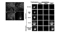
- FIG. 7 illustrates image results obtained from an untreated tissue sample and a single fluorescence treated tissue sample by the multi-wavelength autoanalysis endoscope system according to an exemplary embodiment of the present invention.
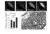
- FIG. 8 is a diagram illustrating an endoscopic imaging image of a tissue sample treated with a plurality of fluorescent materials using a multi-wavelength autoanalysis endoscope system according to an exemplary embodiment of the present invention.
- FIG. 9 is a diagram illustrating an endoscopic imaging image of a living colorectal cancer model mouse using a multi-wavelength automatic analysis endoscope system according to an exemplary embodiment of the present invention.
- FIG. 10 is a diagram illustrating an endoscope photographing image of a living colorectal cancer model pig using a multi-wavelength automatic analysis endoscope system according to an exemplary embodiment of the present invention.
- FIG. 1 is a block diagram of a multi-wavelength automatic analysis system according to an embodiment of the present invention
- Figure 2 is a view showing the structure of a photographing unit according to an embodiment of the present invention
- Figure 3 is a view of the present invention Exemplary drawing showing a photographing unit according to an embodiment.
- the multi-wavelength endoscope system 100 is a system using a camera that allows a human to observe a target and a filter that enables multiple fluorescence imaging. Obtain the hyperspectral radiant luminance of the channel.
- the channel is a unit band for measuring the wavelength, it is possible to obtain a spectral image of each channel by adjusting the filter.
- the endoscope refers to a machine that observes the inside of the body, and includes a bronchoscope, a gastroscope, a laparoscope, and an anal palate.
- the multi-wavelength endoscope system 100 includes a photographing unit 200 and a computing unit 300.
- the photographing unit 200 includes the objective lens 210, the relay lens 220, the beam splitter 230, the first area lens 240, the first area filter 242, the first area camera 244, and the second area.
- An area lens 250, a second area filter 252, and a second area camera 254 are included.
- the light source 400 shown in FIG. 2 positioned outside the multi-wavelength endoscope system 100 emits light to excite the photographed portion.
- the light source 400 may include two or more light sources having different wavelengths in order to photograph an observation target labeled with fluorescent samples having different wavelengths.
- the object to be observed is a marker expressed in cancer, and in this example, the marker may be prepared by using a probe having various wavelength regions and labeled using different fluorescent dyes.
- the objective lens 210 is a lens to which incident light enters.
- the objective lens 210 may provide a focused image regardless of the wavelength in the spectral region of the multi-wavelength endoscope system 100.
- the relay lens 220 is a lens for advancing incident light along the optical axis and outputs light in parallel.
- the relay lens 220 may be a triplet lens having a predetermined focal length.
- the relay lens 220 may be connected to a light source 400 that irradiates light for exciting the photographed portion.
- the relay lens 220 may be positioned inside the endoscope inserted into the body in order to photograph the subject.
- the beam splitter 230 splits parallel light in two directions.
- the beam splitter 230 is a polarization-based beam splitter that processes incident light in the broadband spectrum.
- the beam splitter 230 may cover the spectrum within the visible light region.
- p-polarized light means that it is parallel to the slit direction of the polarizing plate
- s-polarized light means that it is perpendicular to the slit direction of the polarizing plate.
- the first area lens 240 and the second area lens 250 are positioned in the path of the light split from the beam splitter 230, respectively. At this time, in order to adjust the light split from the beam splitter 230 at a predetermined magnification, the first area lens 240 and the second area lens 250 are disposed perpendicular to each other and separated from the beam splitter 230. Can be obtained.
- the first area lens 240 and the second area lens 250 adjust the light split from the beam splitter 230 at an appropriate magnification, and adjust the adjusted light to the first area filter 242 and the second area filter 252. ) Can be delivered.
- the first region filter 242 and the second region filter 252 may pass light in a specified spectral region among the light passing through the first region lens 240 and the second region lens 250, respectively.
- the first region filter 242 and the second region filter 252 may be, for example, a Liquid Crystal Tunable Filter (LCTF), which is a local band pass filter that passes light in a specified spectral region.
- LCTF Liquid Crystal Tunable Filter
- variable liquid crystal filter that passes a channel having a specific wavelength band in the spectral region (for example, 440 nm to 720 nm), it may be controlled to pass light at 10 nm intervals, for example. .
- variable liquid crystal filter is electronically convertible in wavelength, allowing fast wavelength selection.
- variable liquid crystal filter (www.perkinelmer.co.kr) may be controlled to pass light at predetermined intervals, and thus has an effect of putting dozens or hundreds of filters into one filter. This enables multi-wavelength imaging in vivid and diverse colors.
- the first region camera 244 and the second region camera 254 are respectively disposed at the end of the optical path, and pass through the first region filter 242 and the second region filter 252. Measure the light intensity.
- the first area camera 244 and the second area camera 254 may be monochrome cameras. In this case, the first area camera 244 and the second area camera 254 may obtain the intensity of the focused image through a positive triple lens having a predetermined focal length, respectively.
- the computing unit 300 may align the spectral images of each channel acquired by the photographing unit 200 and output radiant luminance according to the wavelength.
- the multispectral image may be composed of a combination of spectroscopic images taken for a plurality of channels.
- the computing unit 300 separates and outputs the multispectral image photographed by the photographing unit 200 according to the wavelength band.
- the site to be photographed may be labeled by fluorescent materials having different wavelengths.
- the spectral image of the capturing region labeled by the capturing unit 200 with the fluorescent material having different wavelengths may display a fluorescent signal having different wavelength ranges.
- a material other than a label labeled with a fluorescent material on the photographing site may receive excitation light emitted from the light source 400 to emit unique light.
- collagen, elastin, keratin, NADH, flavin, porphyrin, etc. contained in biological tissues, which are observed at the site of observation, may cause autofluorescence to reflect light by excitation light. May occur.
- the computing unit 300 of the multi-wavelength endoscope system predetermined the photographing result obtained by the photographing unit 200 so that the user can make an accurate diagnosis using the multispectral image that is the photographing result.
- Each of the fluorescent material is configured to be separated according to the wavelength band of the output.
- the computing unit 300 may extract an autofluorescence spectrum result indicating light intensity according to a wavelength band from a self-fluorescence image of a tissue sample that has not been treated with a fluorescent material (non-treat) in advance.
- the computing unit 300 may extract a single fluorescence spectrum result indicating the intensity of light according to the wavelength band from a plurality of single processed image images of tissue samples each having a single treated treated fluorescent material.
- the computing unit 300 extracts an image spectrum result indicating the light intensity according to the wavelength band from the image data photographed by the photographing unit 200, and the light intensity according to each wavelength band according to the spectrum of the self-fluorescence image.
- the correction is performed by attenuating by as much as possible and deleting the autofluorescence portion.
- the computing unit 300 may calculate a normalization value indicating the intensity of light according to the wavelength band from the single fluorescence spectrum.
- the intensity of light according to the wavelength band may be set to 100, and the ratio of the intensity of light according to each wavelength band may be calculated.
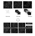
- the computing unit 300 unmixes the observation site labeled with a plurality of fluorescent materials by unmixing the light intensity according to each wavelength band according to a normalization value calculated from a single fluorescence spectrum in the image spectrum result of the image data.
- the photographed video image may be divided into a plurality of video images and displayed to display only the fluorescent material.
- the computing unit 300 performs correction to remove the autofluorescence component from the multispectral image in order to reduce the probability of misdiagnosis when diagnosing a disease according to the photographing result. Only labeled markers can be displayed.
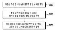
- FIG. 5 is a flowchart illustrating an image processing method using a multi-wavelength automatic analysis endoscope system according to an exemplary embodiment of the present invention.
- a portion to be photographed is labeled with fluorescent materials of various wavelength regions (S110).
- the site to be photographed in the present experimental example may be internal tissues for cancer screening, and the markers expressed in the cancer may be labeled by using a probe labeled with fluorescent materials of various wavelengths in the present embodiment. .
- Table 1 shows the probes of various zones for multiple wavelength detection.
- Probe Name Marker Labeling substance Wavelength range (nm) HMRG g-Glutamyl transpeptidase Rhodamine 501/524 Cetuximab EGFR receptor Flamma553 553/570 Herceptin Her-2 receptor Flamma675 675/700
- the probe may be an antibody probe.
- the antibody probe may be Cetuximab and Herceptin, which are target antibodies to EGFR and HER2, which are highly expressed in tumor and colorectal cancer cells.
- Cetuximab and Herceptin were labeled with the fluorescent materials Flamma-553 and Flamma-675, respectively.
- the probe may be an active probe.
- the active probe may be gGlu-HMRG that exhibits fluorescence activity by meeting GGT ( ⁇ -glutamyltranspeptidase), which shows much expression in tumor cells and colon cancer cells.
- GGT ⁇ -glutamyltranspeptidase
- the HMRG may be labeled with Rhodamine.
- the antibody probe may be administered intravenously to the tail of the mouse 48 hours before the multiwavelength detection endoscope image acquisition, and the active probe may be applied and administered to the large intestine 10 minutes before the multiwavelength detection endoscope is performed.
- the excitation light source is irradiated to the photographing part, and the reflected light is received to obtain a photographed image (S120).
- the light source entered through the endoscope end excites the observation object, and the light reflected from the observation object is transmitted to the first area camera 244 and the second area camera 254 through the relay lens 220. .
- the light source 400 may include two or more light sources having different wavelengths in order to photograph an observation target labeled with fluorescent samples having different wavelengths.
- the first area camera 244 and the second area camera 254 each comprise a first area filter 242 and a second area filter 252, which are variable bandpass filters for passing light in a specified spectral region. It may be implemented as a liquid crystal filter.
- the self-fluorescence part included in the next photographed image is removed and separated according to a predetermined wavelength band and output (S130).
- the fluorescence spectral data obtained through the endoscope outputs a result obtained by dividing the wavelength band through the dividing operation of the computing unit 300, and the self-fluorescence part is removed to finally obtain an image of the wavelength region to be obtained from the observation target. Can be.
- the multi-wavelength endoscope system 100 may store autofluorescence spectra and single fluorescence spectral results indicating the intensity of light according to the wavelength band of a previously stored untreated tissue sample image and a tissue sample image in which a single fluorescent substance is processed.
- a normalization value representing the intensity of light according to the wavelength band calculated from the autofluorescence spectrum and the single fluorescence spectrum may be further stored.
- the multi-wavelength endoscope system 100 corrects the autofluorescence part by attenuating the autofluorescence spectral normalization value in the spectrum of the image data of the observation region labeled with the plurality of fluorescent substances.
- the multi-wavelength endoscope system 100 unmixes the light intensity according to each wavelength band according to a normalization value calculated from a single fluorescence spectrum in the image spectrum result of the image data, and observes the images labeled with a plurality of fluorescent materials.
- the image image of the site may be divided and displayed as a plurality of image images so that only each fluorescent substance appears.
- the disease regions are labeled by using a complex probe labeled with fluorescent materials having different wavelengths. Other probes can be supplemented to accurately image disease sites.
- the computing unit 300 is corrected to remove the autofluorescence component from the multispectral image in order to reduce the probability of misdiagnosis when diagnosing a disease according to the imaging result, and labeled with a fluorescent material Only one marker can be displayed.
- 6A to 6C are graphs illustrating a simulation apparatus for evaluating the performance of the multi-wavelength autoanalytical endoscope system and the simulation results thereof according to an embodiment of the present invention.
- a polyethylene tube (0.28 mm inner diameter, PE-10) of about 15 mm length was prepared to evaluate the performance of a multi-wavelength autoanalytical endoscope system according to an embodiment of the present invention. Fluorescent dye was injected.
- the fluorescent dye used used a plurality of dyes having different colors in the visible light range and includes wavelength ranges close to each other.
- the set wavelength range read by the multi-wavelength endoscope system 100 according to the present embodiment may be 420 nm to 620 nm.
- the computing unit 300 obtains a completed image image file through a decomposition process according to a single fluorescence spectrum result.
- FIG. 7 illustrates image results obtained from an untreated tissue sample and a single fluorescence treated tissue sample by a multi-wavelength autoanalysis endoscope system according to an exemplary embodiment of the present invention
- FIG. 8 illustrates an embodiment of the present invention.
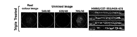
- the multi-wavelength automatic analysis endoscope system according to the endoscope imaging image results of taking a tissue sample treated with a plurality of fluorescent materials.
- the active probe (HMRG) is injected through topical application, antibody probes (Cetuximab-Flamma553, Herceptin-Flamma675) are injected by intravenous injection, and then colonic tissues are extracted using a multi-wavelength autoanalytical endoscopy system. Images for each wavelength were obtained.
- a single probe-treated tissue sample was taken at the observation site, and a single fluorescence spectral result representing light intensity according to the wavelength band was extracted from the captured image data.
- a composite probe labeled with fluorescent materials having different wavelengths is used, and each fluorescent material is labeled according to a single fluorescence spectrum result from image data of a tissue sample labeled with the composite probe.
- FIG. 9 is a diagram illustrating an endoscopic imaging image of a living colorectal cancer model mouse using a multi-wavelength automatic analysis endoscope system according to an exemplary embodiment of the present invention.
- HMRG active probe
- FIG. 10 is a diagram illustrating an endoscopic imaging image of a living colorectal cancer model pig using a multi-wavelength automatic analysis endoscope system according to an exemplary embodiment of the present invention.
- the human-like pigs were injected with an active probe (HMRG) and an antibody probe (Cetuximab-Flamma553, Herceptin-Flamma675), and a multi-wavelength autoanalytical endoscope system was obtained for each wavelength through colonoscopy.
- HMRG active probe
- antibody probe Cetuximab-Flamma553, Herceptin-Flamma675
- the embodiments of the present invention described above are not only implemented through the apparatus and the method, but may be implemented through a program for realizing a function corresponding to the configuration of the embodiments of the present invention or a recording medium on which the program is recorded.
Landscapes
- Health & Medical Sciences (AREA)
- Life Sciences & Earth Sciences (AREA)
- Surgery (AREA)
- Physics & Mathematics (AREA)
- Engineering & Computer Science (AREA)
- General Health & Medical Sciences (AREA)
- Pathology (AREA)
- Medical Informatics (AREA)
- Biophysics (AREA)
- Veterinary Medicine (AREA)
- Biomedical Technology (AREA)
- Heart & Thoracic Surgery (AREA)
- Public Health (AREA)
- Molecular Biology (AREA)
- Animal Behavior & Ethology (AREA)
- Nuclear Medicine, Radiotherapy & Molecular Imaging (AREA)
- Radiology & Medical Imaging (AREA)
- Optics & Photonics (AREA)
- Signal Processing (AREA)
- Spectroscopy & Molecular Physics (AREA)
- Chemical & Material Sciences (AREA)
- Analytical Chemistry (AREA)
- Biochemistry (AREA)
- General Physics & Mathematics (AREA)
- Immunology (AREA)
- Endoscopes (AREA)
Abstract
Description
| 프로브 명칭 | 표지자 | 표지물질 | 파장 영역 (nm) |
| HMRG | g-Glutamyl transpeptidase | Rhodamine | 501/524 |
| Cetuximab | EGFR receptor | Flamma553 | 553/570 |
| Herceptin | Her-2 receptor | Flamma675 | 675/700 |
Claims (13)
- 서로 다른 색을 갖는 복수 개의 형광 물질로 표지한 관찰 부위를 촬영하는 다중 파장 내시경 시스템으로서,상기 관찰 부위에서 반사된 입사광을 제 1 방향과 상기 제 1 방향에 수직인 제 2 방향으로 편광시키고, 상기 제 1 방향과 상기 제 2 방향으로 편광된 상기 입사광의 스펙트럼 영역을 복수의 스펙트럼 채널로 구분하고, 상기 복수의 스펙트럼 채널 각각의 빛의 세기를 측정하여 영상 데이터를 획득하는 촬영부와,상기 관찰 부위를 각각의 상기 형광 물질로 단일 처리하여 촬영한 샘플 영상 데이터로부터 추출된 단일 형광 스펙트럼을 저장하고,상기 단일 형광 스펙트럼을 이용하여 상기 촬영부에서 촬영된 상기 영상 데이터를 상기 복수 개의 형광 물질 중 하나의 형광 물질만이 각각 표시되도록 분리하여 출력하는 컴퓨팅부를 포함하는 다중 파장 내시경 시스템.
- 제 1 항에서,상기 촬영부는상기 입사광을 상기 제 1 방향과 상기 제 1 방향에 수직인 상기 제 2 방향으로 편광시키는 빔 스플리터와,상기 제 1 방향으로 분리된 빛의 경로에 위치하고, 설정된 범위의 빛을 통과 시키는 제 1 영역 필터와,상기 제 2 방향으로 분리된 빛의 경로에 위치하고, 설정된 범위의 빛을 통과 시키는 제 2 영역 필터와,상기 제 1 영역 필터를 통과한 빛의 세기를 측정하는 제 1 영역 카메라와,상기 제 2 영역 필터를 통과한 빛의 세기를 측정하는 제 2 영역 카메라를 포함하는 다중 파장 내시경 시스템.
- 제 2 항에서,상기 컴퓨팅부는상기 형광 물질을 처리하지 않은 상기 관찰 부위를 촬영한 미처리 영상 데이터로부터 추출된 미처리 형광 스펙트럼을 저장하는 다중 파장 내시경 시스템.
- 제 3 항에서,상기 컴퓨팅부는상기 미처리 형광 스펙트럼을 이용하여 상기 촬영부에서 촬영된 상기 영상 데이터에 포함된 자가 형광 성분을 제거하는 보정을 수행하는 다중 파장 내시경 시스템.
- 서로 다른 색을 갖는 복수 개의 형광 물질로 표지한 관찰 부위를 촬영하는 다중 파장 내시경 시스템으로서,상기 관찰 부위에서 반사된 입사광을 제 1 방향과 상기 제 1 방향에 수직인 제 2 방향으로 편광시키는 빔 스플리터와,상기 제 1 방향으로 분리된 빛의 경로에 위치하고, 설정된 범위의 빛을 통과 시키는 제 1 영역 필터와,상기 제 2 방향으로 분리된 빛의 경로에 위치하고, 설정된 범위의 빛을 통과 시키는 제 2 영역 필터와,상기 제 1 영역 필터를 통과한 빛의 세기를 측정하는 제 1 영역 카메라와,상기 제 2 영역 필터를 통과한 빛의 세기를 측정하는 제 2 영역 카메라와,상기 제 1 영역 필터를 통과한 빛의 세기와 상기 제 2 영역 필터를 통과한 빛의 세기를 이용하여 획득한 영상 데이터를 상기 복수 개의 형광 물질 중 하나의 형광 물질만이 표시되도록 분리하여 출력하는 컴퓨팅부를 포함하는 다중 파장 내시경 시스템.
- 제 5 항에서,상기 컴퓨팅부는상기 관찰 부위를 각각의 상기 형광 물질로 단일 처리하여 촬영한 샘플 영상 데이터로부터 추출된 단일 형광 스펙트럼을 저장하고,상기 단일 형광 스펙트럼을 이용하여 상기 영상 데이터를 상기 복수 개의 형광 물질 중 하나의 형광 물질만이 각각 표시되도록 분리하는 다중 파장 내시경 시스템.
- 제 6 항에서,상기 컴퓨팅부는상기 형광 물질을 처리하지 않은 상기 관찰 부위를 촬영한 미처리 영상 데이터로부터 추출된 미처리 형광 스펙트럼을 저장하는 다중 파장 내시경 시스템.
- 제 7 항에서,상기 컴퓨팅부는상기 미처리 형광 스펙트럼을 이용하여 상기 영상 데이터에 포함된 자가 형광 성분을 제거하는 보정을 수행하는 다중 파장 내시경 시스템.
- 다중 파장 내시경 시스템이 영상을 처리하는 방법으로서,서로 다른 색을 갖는 복수 개의 형광 물질로 표지한 관찰 부위에 광원을 조사하는 단계와,상기 관찰 부위로부터 반사한 빛을 전달받아 영상 데이터를 획득하는 단계와,상기 영상 데이터를 상기 복수 개의 형광 물질 중 하나의 형광 물질만이 표시되도록 분리하는 단계와,상기 파장 대역에 따라 분리된 상기 영상 데이터를 출력하는 단계를 포함하는 영상 처리 방법.
- 제 9 항에서,상기 관찰 부위를 각각의 상기 형광 물질로 단일 처리하여 촬영한 샘플 영상 데이터로부터 단일 형광 스펙트럼을 추출하는 단계를 더 포함하는 영상 처리 방법.
- 제 10 항에서,상기 영상 데이터를 상기 복수 개의 형광 물질 중 하나의 형광 물질만이 표시되도록 분리하는 상기 단계는상기 단일 형광 스펙트럼을 이용하여 상기 영상 데이터를 상기 복수 개의 형광 물질 중 하나의 형광 물질만이 각각 표시되도록 분리하는 영상 처리 방법.
- 제 9 항에서,상기 형광 물질을 처리하지 않은 관찰 부위를 촬영한 미처리 영상 데이터로부터 미처리 형광 스펙트럼을 추출하는 단계를 더 포함하는 영상 처리 방법.
- 제 12 항에서,상기 미처리 형광 스펙트럼을 이용하여 상기 영상 데이터에 포함된 자가 형광 성분을 제거하는 보정을 수행하는 단계를 더 포함하는 영상 처리 방법.
Priority Applications (5)
| Application Number | Priority Date | Filing Date | Title |
|---|---|---|---|
| AU2017346249A AU2017346249B2 (en) | 2015-11-02 | 2017-10-18 | Multi-wavelength endoscopic system and image processing method using same |
| US16/342,900 US10610088B2 (en) | 2016-10-18 | 2017-10-18 | Multi-wavelength endoscopic system and image processing method using same |
| RU2019112728A RU2716680C1 (ru) | 2016-10-18 | 2017-10-18 | Многоволновая эндоскопическая система и способ обработки изображений с её использованием |
| CA3040851A CA3040851A1 (en) | 2015-11-02 | 2017-10-18 | Multi-wavelength endoscopic system and image processing method using same |
| SG11201902989YA SG11201902989YA (en) | 2015-11-02 | 2017-10-18 | Multi-wavelength endoscopic system and image processing method using same |
Applications Claiming Priority (3)
| Application Number | Priority Date | Filing Date | Title |
|---|---|---|---|
| KR20150153144 | 2015-11-02 | ||
| KR10-2016-0135305 | 2016-10-18 | ||
| KR1020160135305A KR101978838B1 (ko) | 2015-11-02 | 2016-10-18 | 다중 파장 내시경 시스템 및 이를 이용한 영상 처리 방법 |
Publications (1)
| Publication Number | Publication Date |
|---|---|
| WO2018074833A1 true WO2018074833A1 (ko) | 2018-04-26 |
Family
ID=66674216
Family Applications (1)
| Application Number | Title | Priority Date | Filing Date |
|---|---|---|---|
| PCT/KR2017/011522 Ceased WO2018074833A1 (ko) | 2015-11-02 | 2017-10-18 | 다중 파장 내시경 시스템 및 이를 이용한 영상 처리 방법 |
Country Status (5)
| Country | Link |
|---|---|
| KR (1) | KR101978838B1 (ko) |
| AU (1) | AU2017346249B2 (ko) |
| CA (1) | CA3040851A1 (ko) |
| SG (1) | SG11201902989YA (ko) |
| WO (1) | WO2018074833A1 (ko) |
Cited By (1)
| Publication number | Priority date | Publication date | Assignee | Title |
|---|---|---|---|---|
| US20210153808A1 (en) * | 2018-06-22 | 2021-05-27 | Ai Medical Service Inc. | Diagnostic assistance method, diagnostic assistance system, diagnostic assistance program, and computer-readable recording medium storing therein diagnostic assistance program for disease based on endoscopic image of digestive organ |
Families Citing this family (5)
| Publication number | Priority date | Publication date | Assignee | Title |
|---|---|---|---|---|
| US12292564B2 (en) | 2019-04-08 | 2025-05-06 | Activ Surgical, Inc. | Systems and methods for medical imaging |
| KR102282179B1 (ko) * | 2019-04-30 | 2021-07-27 | 을지대학교 산학협력단 | 손잡이형 수술용 프로브 |
| CN114599263A (zh) | 2019-08-21 | 2022-06-07 | 艾科缇弗外科公司 | 用于医疗成像的系统和方法 |
| CN115389254A (zh) * | 2022-07-13 | 2022-11-25 | 北京市轨道交通学会 | 一种用于城市轨道交通隧道结构的微创探查方法及装置 |
| DE102023135636A1 (de) * | 2023-12-18 | 2025-06-18 | Karl Storz Se & Co. Kg | Bildgebungsvorrichtung, insbesondere endoskopische, exoskopische und/oder mikroskopische Bildgebungsvorrichtung |
Citations (5)
| Publication number | Priority date | Publication date | Assignee | Title |
|---|---|---|---|---|
| JP2003339623A (ja) * | 2002-05-27 | 2003-12-02 | Fuji Photo Film Co Ltd | 蛍光診断情報生成方法および装置 |
| KR20070054761A (ko) * | 2003-10-28 | 2007-05-29 | 베라라이트, 인코오포레이티드 | 조직 형광을 이용한, 당화 최종산물 또는 질병 상태 측정의판정방법 |
| JP4954699B2 (ja) * | 2006-12-28 | 2012-06-20 | オリンパス株式会社 | 蛍光内視鏡システム |
| KR101243183B1 (ko) * | 2011-04-08 | 2013-03-14 | 한국전기연구원 | 최종당화산물의 자가형광 측정 장치 |
| KR20160117440A (ko) * | 2013-12-31 | 2016-10-10 | 메모리얼 슬로안-케터링 캔서 센터 | 실시간 형광 소스들의 다채널 이미징을 위한 시스템들, 방법들 및 장치 |
Family Cites Families (4)
| Publication number | Priority date | Publication date | Assignee | Title |
|---|---|---|---|---|
| KR100411631B1 (ko) * | 2001-10-18 | 2003-12-18 | 주식회사 메디미르 | 형광 내시경 장치 및 그 장치를 이용한 진단부위 조상 방법 |
| US20090131800A1 (en) * | 2007-11-15 | 2009-05-21 | Carestream Health, Inc. | Multimodal imaging system for tissue imaging |
| JP5506472B2 (ja) * | 2010-03-12 | 2014-05-28 | オリンパス株式会社 | 蛍光内視鏡装置 |
| KR102028199B1 (ko) * | 2012-08-28 | 2019-10-04 | 한국전자통신연구원 | 의료 진단장치 및 그 조작방법 |
-
2016
- 2016-10-18 KR KR1020160135305A patent/KR101978838B1/ko not_active Expired - Fee Related
-
2017
- 2017-10-18 WO PCT/KR2017/011522 patent/WO2018074833A1/ko not_active Ceased
- 2017-10-18 AU AU2017346249A patent/AU2017346249B2/en not_active Ceased
- 2017-10-18 SG SG11201902989YA patent/SG11201902989YA/en unknown
- 2017-10-18 CA CA3040851A patent/CA3040851A1/en not_active Abandoned
Patent Citations (5)
| Publication number | Priority date | Publication date | Assignee | Title |
|---|---|---|---|---|
| JP2003339623A (ja) * | 2002-05-27 | 2003-12-02 | Fuji Photo Film Co Ltd | 蛍光診断情報生成方法および装置 |
| KR20070054761A (ko) * | 2003-10-28 | 2007-05-29 | 베라라이트, 인코오포레이티드 | 조직 형광을 이용한, 당화 최종산물 또는 질병 상태 측정의판정방법 |
| JP4954699B2 (ja) * | 2006-12-28 | 2012-06-20 | オリンパス株式会社 | 蛍光内視鏡システム |
| KR101243183B1 (ko) * | 2011-04-08 | 2013-03-14 | 한국전기연구원 | 최종당화산물의 자가형광 측정 장치 |
| KR20160117440A (ko) * | 2013-12-31 | 2016-10-10 | 메모리얼 슬로안-케터링 캔서 센터 | 실시간 형광 소스들의 다채널 이미징을 위한 시스템들, 방법들 및 장치 |
Cited By (2)
| Publication number | Priority date | Publication date | Assignee | Title |
|---|---|---|---|---|
| US20210153808A1 (en) * | 2018-06-22 | 2021-05-27 | Ai Medical Service Inc. | Diagnostic assistance method, diagnostic assistance system, diagnostic assistance program, and computer-readable recording medium storing therein diagnostic assistance program for disease based on endoscopic image of digestive organ |
| US12048413B2 (en) * | 2018-06-22 | 2024-07-30 | Ai Medical Service Inc. | Diagnostic assistance method, diagnostic assistance system, diagnostic assistance program, and computer-readable recording medium storing therein diagnostic assistance program for disease based on endoscopic image of digestive organ |
Also Published As
| Publication number | Publication date |
|---|---|
| SG11201902989YA (en) | 2019-05-30 |
| KR20170051264A (ko) | 2017-05-11 |
| CA3040851A1 (en) | 2018-04-26 |
| AU2017346249A1 (en) | 2019-04-18 |
| KR101978838B1 (ko) | 2019-05-16 |
| AU2017346249B2 (en) | 2019-11-21 |
Similar Documents
| Publication | Publication Date | Title |
|---|---|---|
| WO2018074833A1 (ko) | 다중 파장 내시경 시스템 및 이를 이용한 영상 처리 방법 | |
| CN1802560B (zh) | 使用多激发-发射对和同时多信道图像检测进行荧光成像的方法和装置 | |
| US8285015B2 (en) | Simultaneous acquisition of differing image types | |
| US5833617A (en) | Fluorescence detecting apparatus | |
| JP2001017379A (ja) | 蛍光診断装置 | |
| JPH11326050A (ja) | 画像分析装置 | |
| JPH10325798A (ja) | 顕微鏡装置 | |
| JP2006296635A (ja) | 内視鏡装置 | |
| Yoon et al. | First experience in clinical application of hyperspectral endoscopy for evaluation of colonic polyps | |
| WO2019100450A1 (zh) | 一种多功能内窥镜系统 | |
| JPH0970384A (ja) | 蛍光診断用電子内視鏡装置 | |
| JP6404687B2 (ja) | 蛍光イメージング装置及び蛍光イメージング方法 | |
| WO2023013860A1 (ko) | 멀티스펙트럼 내시경 및 이를 포함하는 내시경 시스템 | |
| JP2007528505A (ja) | マルチチャンネル光学画像法 | |
| US10610088B2 (en) | Multi-wavelength endoscopic system and image processing method using same | |
| CN114947696A (zh) | 一种白光-窄带-荧光一体化内窥镜及其使用方法 | |
| JP4495513B2 (ja) | 蛍光内視鏡装置 | |
| KR20180066645A (ko) | 형광 내시경 시스템 | |
| SE1351503A1 (sv) | System och metod för fluorescensmikroskopi med detektering av ljusemission från multipla fluorokromer | |
| JP2007313171A (ja) | 内視鏡システム | |
| Andersson-Engels et al. | Multicolor fluorescence imaging system for tissue diagnostics | |
| JPS63252134A (ja) | 螢光検出を利用したがん診断装置 | |
| Papayan et al. | Video-endoscopy system for photodynamic theranostics of central lung cancer | |
| JP3810337B2 (ja) | 撮像装置 | |
| WO2021033787A1 (ko) | 단일 컬러 카메라를 이용하고 가시광선 및 근적외선 영상 동시 획득이 가능한 가시광선 및 근적외선 영상 제공 시스템 및 방법 |
Legal Events
| Date | Code | Title | Description |
|---|---|---|---|
| 121 | Ep: the epo has been informed by wipo that ep was designated in this application |
Ref document number: 17862272 Country of ref document: EP Kind code of ref document: A1 |
|
| ENP | Entry into the national phase |
Ref document number: 3040851 Country of ref document: CA |
|
| ENP | Entry into the national phase |
Ref document number: 2017346249 Country of ref document: AU Date of ref document: 20171018 Kind code of ref document: A |
|
| NENP | Non-entry into the national phase |
Ref country code: DE |
|
| 122 | Ep: pct application non-entry in european phase |
Ref document number: 17862272 Country of ref document: EP Kind code of ref document: A1 |