WO2018074459A1 - 画像処理装置、画像処理方法及び画像処理プログラム - Google Patents
画像処理装置、画像処理方法及び画像処理プログラム Download PDFInfo
- Publication number
- WO2018074459A1 WO2018074459A1 PCT/JP2017/037500 JP2017037500W WO2018074459A1 WO 2018074459 A1 WO2018074459 A1 WO 2018074459A1 JP 2017037500 W JP2017037500 W JP 2017037500W WO 2018074459 A1 WO2018074459 A1 WO 2018074459A1
- Authority
- WO
- WIPO (PCT)
- Prior art keywords
- image
- adjacent pixels
- pixel
- value
- image processing
- Prior art date
- Legal status (The legal status is an assumption and is not a legal conclusion. Google has not performed a legal analysis and makes no representation as to the accuracy of the status listed.)
- Ceased
Links
Images






Classifications
-
- G—PHYSICS
- G06—COMPUTING OR CALCULATING; COUNTING
- G06T—IMAGE DATA PROCESSING OR GENERATION, IN GENERAL
- G06T5/00—Image enhancement or restoration
- G06T5/70—Denoising; Smoothing
-
- G—PHYSICS
- G06—COMPUTING OR CALCULATING; COUNTING
- G06T—IMAGE DATA PROCESSING OR GENERATION, IN GENERAL
- G06T2207/00—Indexing scheme for image analysis or image enhancement
- G06T2207/10—Image acquisition modality
- G06T2207/10072—Tomographic images
- G06T2207/10101—Optical tomography; Optical coherence tomography [OCT]
Definitions
- the present invention relates to an image processing apparatus, an image processing method, and an image processing program for processing an image including noise to generate an image with reduced noise.
- An image with a poor signal-to-noise ratio contains a lot of noise consisting of white points and black points. These noises can cause incorrect analysis / analysis results or increase the variation in the results obtained during image processing to analyze / analyze images to obtain some information. It becomes.
- S / N signal-to-noise ratio
- a structure to be considered as abnormal is very small, unclear, or narrow.
- the noise point is mistakenly extracted as the target structure of interest, or the noise component breaks down the structure of interest, so that the structure that was originally a single structure is divided into a plurality of structures. It may cause you to recognize it as a structure. Therefore, how to remove noise has become a very important issue in the process of image processing.
- the present invention has been made in view of the above points, and an image processing apparatus, an image processing method, and an image processing program capable of reducing noise in an image while maintaining the characteristics of a structure in the image.
- the purpose is to provide.
- the present invention includes a calculation unit for calculating a difference value between a luminance value of a target pixel and each of a plurality of adjacent pixels located around the target pixel; Counting means for counting the number of the adjacent pixels whose calculated difference value is equal to or less than a predetermined threshold as the number of non-corresponding adjacent pixels, and when the number of non-corresponding adjacent pixels is equal to or less than a predetermined number,
- An image processing apparatus is provided that includes a replacement unit that replaces the luminance value of the target pixel with an average value of luminance values of adjacent pixels (Invention 1).
- the luminance value of the target pixel is not simply averaged using the luminance values of the peripheral pixels (adjacent pixels located around the target pixel). Only when the pixel of interest is clearly brighter or darker than the surrounding pixel based on the difference value from the luminance value of the surrounding pixel, and only when the pixel of interest is determined to be noise consisting of a white point or a black point Since the luminance value of the target pixel is replaced with the average value of the luminance values of the peripheral pixels, only noise in the image can be removed. As a result, noise reduction processing can be performed without impairing features such as the shape, brightness, and color of characteristic structures present in the image.
- the said calculation means calculates
- the average value of the luminance values of all the plurality of adjacent pixels is used.
- Brightness of target pixel It may be replaced by the (invention 2).
- the image in which the target image exists is one tomographic image among a plurality of continuous tomographic images
- the plurality of adjacent pixels are the one tomographic image and tomographic images before and after the tomographic image. It may be a plurality of adjacent pixels spatially located around the pixel of interest in the image (Invention 3).
- the characteristics of the structure of interest are not impaired even when consecutive tomographic images are handled, and the structures included in the preceding and following tomographic images are reflected in the tomographic image of interest after processing. Therefore, noise reduction processing can be performed.
- the present invention provides a calculation step of calculating a difference value between the luminance value of the target pixel and each of the luminance values of a plurality of adjacent pixels located around the target pixel, and the calculated difference value is a predetermined value.
- a replacement step for replacing the luminance value of the pixel of interest (invention 4).
- the luminance value of the target pixel is not simply averaged using the luminance values of the peripheral pixels (adjacent pixels located around the target pixel). Only when the pixel of interest is clearly brighter or darker than the surrounding pixel based on the difference value from the luminance value of the surrounding pixel, and only when the pixel of interest is determined to be noise consisting of a white point or a black point Since the luminance value of the target pixel is replaced with the average value of the luminance values of the peripheral pixels, only noise in the image can be removed. As a result, noise reduction processing can be performed without impairing features such as the shape, brightness, and color of characteristic structures present in the image.
- the counting step the number of the adjacent pixels whose first difference value is equal to or less than a predetermined first threshold While counting as the number of corresponding adjacent pixels, the number of the adjacent pixels whose second difference value is equal to or smaller than a predetermined second threshold is counted as a second number of non-corresponding adjacent pixels.
- the average value of the luminance values of all the plurality of adjacent pixels is obtained. It may be replaced with the luminance value of the serial pixel of interest (invention 5).
- the image in which the target image exists is one tomographic image among a plurality of continuous tomographic images
- the plurality of adjacent images are the one tomographic image and tomographic images before and after the tomographic image.
- a plurality of adjacent pixels spatially located around the pixel of interest in an image may be used (invention 6).
- the characteristics of the structure of interest are not impaired even when consecutive tomographic images are handled, and the structures included in the preceding and following tomographic images are reflected in the tomographic image of interest after processing. Therefore, noise reduction processing can be performed.
- the present invention is for causing a computer to function as an image processing apparatus according to any one of inventions 1 to 3, or for causing a computer to execute the image processing method according to any one of inventions 4 to 6.
- An image processing program is provided (Invention 7).
- the image processing apparatus According to the image processing apparatus, the image processing method, and the image processing program of the present invention, it is possible to reduce noise in the image while maintaining the characteristics of the structure in the image.
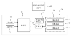
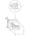
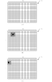
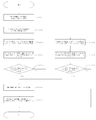
- FIG. 1 is a block diagram illustrating an overall configuration of an image processing apparatus according to an embodiment of the present invention. It is explanatory drawing which shows the state which acquires a fundus tomographic image by scanning a fundus. It is explanatory drawing which shows typically the relationship between the attention pixel and adjacent pixel in the case of processing a single image with the image processing apparatus which concerns on this embodiment. It is a flowchart which shows the flow of the image processing in this embodiment. It is explanatory drawing (the 1) which shows typically the relationship between the attention pixel and adjacent pixel in the case of processing several continuous tomographic images with the image processing apparatus which concerns on this embodiment.
- FIG. 1 is a block diagram showing the entire system for acquiring and processing a tomographic image of the fundus of the eye to be examined.
- the tomographic imaging apparatus 10 is an apparatus (OCT: Optical Coherence Tomography) that captures a tomographic image of the fundus of the subject's eye and operates, for example, in the Fourier domain method. Since the tomographic imaging apparatus 10 is known, detailed description thereof is omitted, but the tomographic imaging apparatus 10 is provided with a low coherence light source, and light from the low coherence light source is divided into reference light and signal light.
- the signal light is raster scanned on the fundus oculi E, for example, in the X and Y directions.
- the signal light scanned and reflected by the fundus E is superimposed on the reference light reflected by the reference mirror to generate interference light, and an OCT signal indicating information in the depth direction (Z direction) of the fundus is generated based on the interference light.
- OCT Optical Coherence
- the image processing apparatus 20 includes a control unit 21 realized by a computer including a CPU, a RAM, a ROM, and the like, and the control unit 21 controls the entire image processing by executing an image processing program.
- the image processing apparatus 20 is provided with a tomographic image forming unit 22.
- the tomographic image forming unit 22 is realized by a dedicated electronic circuit that executes a known analysis method such as a Fourier domain method, or an image processing program executed by the CPU, and an OCT signal generated by the tomographic imaging apparatus 10. Based on the above, a tomographic image of the fundus of the eye to be examined is formed.
- the tomographic image B N is an image having a size of m ⁇ n pixels and is also called a B scan image. .
- the t pieces of tomographic images B N formed by the tomographic image forming unit 22 or the three-dimensional volume image constructed from these t pieces of tomographic images B N are, for example, a storage unit configured by a semiconductor memory, a hard disk device, or the like. 23.
- the storage unit 23 further stores the above-described image processing program and the like.
- the image processing device 20 is provided with an image processing unit 30.
- the image processing unit 30 includes a calculation unit 31, a counting unit 32, and a replacement unit 33.
- the calculation unit 31 calculates difference values between the luminance value of the target pixel in the image to be processed and the luminance values of each of a plurality of adjacent pixels located around the target pixel, and counts them.
- the means 32 counts the number of adjacent pixels whose calculated difference value is equal to or less than a predetermined threshold (luminance difference threshold) as the number of non-applicable adjacent pixels, and the replacement means 33 counts the number of non-applicable adjacent pixels to a predetermined number (non-applicable) If it is equal to or less than the permissible number), the luminance value of the target pixel is replaced with the average value of the luminance values of a plurality of adjacent pixels.
- a predetermined threshold luminance difference threshold
- the display unit 24 is configured by a display device such as an LCD, for example, and displays accompanying information such as a tomographic image stored in the storage unit 23, an image generated or processed by the image processing device 20, information about a subject, and the like. .
- the operation unit 25 includes, for example, a mouse, a keyboard, an operation pen, a pointer, an operation panel, and the like.
- the operation unit 25 is used to select an image displayed on the display unit 24 or to give an instruction to the image processing apparatus 20 or the like. It is done.
- a tomographic image of the fundus of the eye E is photographed by the tomographic imaging apparatus 10, and noise in the tomographic image of the fundus of the eye to be examined generated by the tomographic image forming unit 22 based on the photographed tomographic image is subjected to image processing.
- a flow of removal by image processing by the unit 30 will be described.
- the processing target image B T a piece of the resulting t tomographic image B N, describing the flow to remove noise from the single processing target image B T.
- the processing target image BT is an image having a size of m ⁇ n pixels, as shown in FIG. It shows a flow for removing noise from the processed image B T in FIG.
- s101 to s107 in FIG. 4 correspond to steps 101 to 107 in the description of the flow described below.
- calculation means 31 first is to set one pixel of interest in the target image B T as a target pixel P, pixels positioned around the target pixel P, i.e. the upper and lower pixel P
- FIG. 3 (B) showing the fourth column from the left of the target image B T, the pixel of interest P set in the third row from the top, eight relationship adjacent pixels p i located therearound.
- adjacent pixels is eight set in the case of setting the end portion of the target image P in the processing target image B T, if the pixel of interest P is set to the end in the processing target image B T
- the adjacent pixels may be appropriately set within 8 according to the position of the target pixel. For example the first column the pixel of interest from the left of the processing target image B T, when it is set in the third row from the top, as shown in FIG. 3 (C), on the pixel of interest P, down, right, right Five pixels located diagonally above and diagonally below right are set as adjacent pixels.
- pixels located above, below, left, and right of the target pixel may be set as adjacent pixels, In addition to eight pixels positioned so as to be in contact with the four corners of the pixel of interest, 24 pixels including 16 pixels positioned further outside are set as adjacent pixels. You may change suitably.
- the calculation means 31 After obtaining the luminance value D of the pixel of interest P and the luminance value d i of the adjacent pixel p i , the calculation means 31 first subtracts the luminance value d i of each adjacent pixel p i from the luminance value D of the pixel of interest P. A difference value is calculated for each of the eight adjacent pixels p i (step 103a). This first difference value is calculated by the number of adjacent pixels, and is used to estimate whether the pixel of interest P is white point noise.
- the counting means 32 compares whether or not the calculated first difference value is equal to or less than the first luminance difference threshold value PKT stored in the storage unit 23 in advance, and the first luminance difference threshold value PKT.
- the number of adjacent pixels that was below is counted as the first non-applicable number of adjacent pixels (step 104a). That is, the number of adjacent pixels satisfying the conditional expression: the luminance value D of the target pixel P ⁇ the luminance value d i ⁇ PKT of the adjacent pixel p i is the first non-applicable adjacent pixel number.
- the replacement unit 33 determines whether the first non-applicable adjacent pixel number is equal to or less than the first non-applicable allowable number PFT stored in the storage unit 23 in advance. (Step 105a). If the number of first non-applicable adjacent pixels is equal to or less than the first non-applicable permissible number PFT, the target pixel P is determined to be white point noise.
- the calculation unit 31 obtains a second value obtained by subtracting the luminance value D of the target pixel P from the luminance value d i of each adjacent pixel p i .
- a difference value is calculated for each of the eight adjacent pixels p i (step 103b). Similar to the first difference value, this second difference value is also calculated by the number of adjacent pixels, and is used to estimate whether the pixel of interest P is black point noise.
- the counting means 32 compares whether or not the calculated second difference value is equal to or less than the second luminance difference threshold value HLT stored in the storage unit 23 in advance, and the second luminance difference threshold value HLT is compared.
- the number of adjacent pixels that was below is counted as the second non-applicable number of adjacent pixels (step 104b). That is, the conditional expression: the luminance value d i adjacent pixels p i - the number of neighboring pixels satisfying the luminance value D ⁇ HLT of the pixel of interest P becomes the second non-relevant number of adjacent pixels.
- the replacement unit 33 determines whether the second non-applicable adjacent pixel number is equal to or less than the second non-applicable allowable number HFT stored in the storage unit 23 in advance. (Step 105b). If the number of second non-applicable adjacent pixels is equal to or less than the second non-applicable allowable number HFT, the target pixel P is determined to be black point noise.
- the replacement unit 33 calculates the average value of the luminance values d i of the adjacent pixels p i. Calculate (step 106). Then, an image in which the luminance value of the target pixel P is replaced with the calculated average value is generated (step 107) and stored in the storage unit 23.
- the first non-applicable adjacent pixel number is not less than or equal to the first non-applicable allowable number PFT, and as a result of the determination in step 105b, the second non-applicable adjacent pixel number is equal to or less than the second non-applicable allowable number HFT. Otherwise, the luminance value of the target pixel P is left as it is without being replaced with the average value.
- the present invention compares the pixel of interest in the image to be processed with the adjacent pixels located around it, and when the luminance value of the pixel of interest is brighter than the adjacent pixel by a predetermined value, Alternatively, in the case of darkness, the average value of adjacent pixels is replaced.
- Increasing the luminance difference between the adjacent pixel used for replacement and the target pixel that is, setting the first luminance difference threshold and the second luminance difference threshold described above to be large reduces the number of target pixels to be replaced, and conversely setting it to be small. The number of target pixels to be replaced increases.
- the most strict determination formula is used to determine whether the target pixel is brighter than a predetermined value than all adjacent pixels, or whether the target pixel is darker than a predetermined value than all adjacent pixels. It can also be used. In this case, by setting the first non-applicable permissible number and the second non-applicable permissible number to 0, the target pixel is brighter than a predetermined value than all the adjacent pixels, or the target pixel is more than all the adjacent pixels. Only when the brightness is darker than the predetermined value, the process of replacing the luminance value of the target pixel with the average value of the luminance values of the adjacent pixels is performed.
- the number of target pixels replaced with the average value decreases, and the replacement is performed as the first non-applicable permissible number or the second non-applicable permissible number is increased.
- the number of pixels of interest increases.
- the same value may be used for the first luminance difference threshold and the second luminance difference threshold, or different numerical values may be set individually. Moreover, the same value may be used for the first non-applicable allowable number and the second non-applicable allowable number, or different numerical values may be set individually. For these condition values stored in advance in the storage unit 23, optimum values should be examined in advance according to the quality of the image and the properties of the structure to be extracted (shape, brightness, size, etc.). Can do.
- the image processing device and the image processing method instead of simply averaging the luminance value of the target pixel using the luminance values of the peripheral pixels (adjacent pixels positioned around the target pixel), Based on the difference between the luminance value of the pixel of interest and the luminance value of the surrounding pixels, it is determined whether the pixel of interest is clearly brighter or darker than the surrounding pixels, and the pixel of interest is noise consisting of a white point or a black point. Only when it is determined that the luminance value of the target pixel is replaced with the average value of the luminance values of the surrounding pixels, only noise in the image can be removed. As a result, noise reduction processing can be performed without impairing features such as the shape, brightness, and color of characteristic structures present in the image.
- one of the tomographic images B N acquired by the tomographic imaging apparatus 10 is used as the processing target image B T , but the fundus plane acquired by a scanning laser ophthalmoscope (SLO) is used. It is also possible to remove the noise by performing the same image processing as heretofore with the image as the processing target image.
- SLO scanning laser ophthalmoscope
- a tomographic image of t Like obtained from the place which is spatially continuous, as shown in FIG. 2 B N
- a method of setting a pixel of interest and an adjacent pixel using one of the images as a processing target image B T and using the tomographic image B T-1 and the tomographic image B T + 1 before and after the processing target image B T will be described.
- the tomographic image B T-1 and the tomographic image B T + 1 are tomographic images continuous to the processing target image B T in the Y direction shown in FIG. 2, and have a size of m ⁇ n pixels as in the processing target image B T. It is an image that has.
- the tomographic imaging apparatus 10 and the image processing apparatus 20 used for image processing in this modification have the same configuration as described above, detailed description is omitted, but the tomographic image B T-1 and the processing target image B are omitted. Both T and tomographic image B T + 1 are stored in the storage unit 23.
- one pixel of interest in the processing target image B T is set as a target pixel Q, and the processing target image B T and the tomographic images B T-1 and B T + 1 before and after the processing target image B T are spatially
- the adjacent pixel q i in this modification example includes a total of eight pixels, that is, a pixel located at the top, bottom, left, and right of the target pixel Q in the processing target image B T and a pixel located so as to be in contact with the four corners of the target pixel.
- FIG. 6 shows a state in which only the target pixel Q and the adjacent pixel q i are cut out from the state in which the processing target image B T and the tomographic images B T ⁇ 1 and the tomographic image B T + 1 before and after the processing target image B T are arranged.
- adjacent pixels is 26 set in the case of setting the end portion of the pixel of interest Q in the processing target image B T, when the target pixel Q is set to end the process target image B T
- the adjacent pixels may be appropriately set within 26 in accordance with the position of the target pixel. Even when there are no continuous tomographic images before and after, adjacent pixels may be appropriately set within 26 according to the position of the target pixel.
- the method for setting adjacent pixels may be appropriately changed according to the type of image to be processed, the purpose of noise removal, and the like.
- Image processing flow is omitted because it is similar to the flow that removes noise from a single processed image B T.
- OCT angiography the front image of the (OCTA Optical Coherence Tomography Angiography) Retinal vascular generated using (En Face image) It is also possible to perform image processing on the image and remove noise from the image.
- the OCT angiography generates an angiographic image without using a fluorescent agent, and the same portion of the fundus E of the eye to be examined is continuously detected using the tomographic imaging apparatus 10 described in the above embodiment.
- a plurality of images are taken and a change in the acquired time difference tomographic image (B scan image) of several ms is regarded as a blood flow change to generate a front image.
- a known change detection method such as an OMAG (Optical Microangiography) method, an SSADA (Split-spectrum Amplitude-) is applied to a group of B scan images obtained by continuously capturing a plurality of identical portions of the fundus E of the eye to be examined.
- decorrelation (Angiography) method is applied to generate one blood flow tomographic image. This is repeated while changing the scan position in the Y direction with respect to the observation target region, and one three-dimensional data set is generated from a plurality of continuous blood flow tomographic images obtained. That is, the three-dimensional data set is data in which the observation target region of the fundus E of the eye to be examined is three-dimensionally modeled.
- each B scan image constituting the B scan image group is a tomographic image on the XZ plane in FIG. 2
- the blood flow tomographic image generated from the B scan image group is also an XZ plane tomographic image.
- a blood flow tomographic image is generated as a plurality of XY plane tomographic images continuous in the Z direction from the data set.
- a front image of a retinal blood vessel is generated by overlaying a plurality of XY plane blood flow tomographic images continuous in the Z direction.
- the images are the tomographic image B T-1 and the tomographic image B T + 1
- the same image processing method as that described in the first modified example is applied to the front image of the retinal blood vessel generated by OCT angiography. And only noise in the front image can be removed.
- FIG. 7 is an explanatory diagram prepared for comparing the average value method and the median value method, which are conventional methods for removing noise in an image, and the image processing method of the present invention.
- FIG. 7A shows a test image including a simple square target structure in order to compare the effect of the present invention with a general noise removal method.
- 255 and gray have a luminance value of 128.
- Three square structures of interest are lined up from the top of the image, each with a white, gray, and black background. When the background is white, the black noise point is displayed. When the background is black, the white noise point is displayed. If the background is gray, the same number of white and black noise points are included.
- the pixel of interest was moved in the horizontal direction from the upper left for each pixel of the image, and the following image processing was performed on all the pixels until it reached the lower right.
- the first method is to obtain an average value of 8 neighboring 9 pixels including the target pixel and replace the average value with the target pixel, which is called an average value method.
- the second is a method of rearranging 8 neighboring 9 pixels including the target pixel in ascending order from the lowest luminance, and replacing the fifth pixel with the target pixel, which is called a median method.
- the third is the image processing method of the present invention, that is, when the target pixel and the adjacent eight pixels are compared, and the luminance value of the target pixel is larger than a predetermined value compared to the luminance value of the adjacent pixel, or In this case, an average value of adjacent 8 pixels is obtained when the pixel is small, and is replaced with the pixel of interest.
- noise points are averaged and blurred by surrounding pixels, so that a large luminance difference from the originally existing surrounding pixels is reduced, but the pixels around the noise points are reduced. The value was changed and changed.
- the contour of the target shape is also blurred, it cannot be used for the purpose of maintaining the shape of the structure of interest and reducing noise.
- the median method has an excellent effect in removing noise points, the vertex portion of the target shape is lost. This is because the pixel derived from the structure occupying 9 pixels in the vicinity of 8 in the corner or the tip of the structure of interest becomes a minority, and the non-structure pixel occupying the majority is selected as the median value. It is.
- the first luminance difference threshold is set to 48 and the first non-applicable permissible number is set to 1 for white point detection, and the second luminance difference threshold is set to 6 for black point detection. 2
- the non-applicable allowable number is set to 4 and the image processing result is evaluated, as shown in FIG. 7D, the image processing method of the present invention completely removes noise and maintains the shape accurately. We were able to.
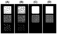
- FIG. 8 is a diagram for comparing the effect of processing by the average value method and the median value method and the image processing method of the present invention on an image including a complex shape, assuming a target structure in the image. It is explanatory drawing prepared, (A) shows the test image containing a complicated shape, (B) shows the average value method, (C) shows the median method, (D) shows the image processed by the method of this invention. .
- complex shapes there are a structure with high and low brightness (A-upper), a structure with thin lines combined (A-middle), and a structure with protrusions (A-lower). These shapes did not include noise points, and the purpose was to clarify how each noise removal method affects the shape of the structure.
- the outline was blurred in any shape, and the luminance of the shape was greatly reduced.
- the adjacent pixels occupy a large number of low-luminance background pixels around the structure, and the information on the structure is greatly impaired by averaging. It was.
- FIG. 8C although the contour of the shape was not blurred or the luminance was not lowered by the median method, the thin line-shaped portion and the tip portion in the structure in the shape were completely extracted. The shape did not remain the prototype of the test image. In the structure (A-middle) to which the thin lines are combined and the structure with protrusions (A-bottom), these portions were not extracted, and thus were extracted as a plurality of fragments.
- the image processing method of the present invention when the luminance difference threshold and the non-applicable allowable number determined by preliminary examination in Example 1 are used, as shown in FIG. Although the extraction omission was observed, the structure could be extracted while maintaining the shape higher than other methods. That is, when considered in conjunction with Example 1, it is shown that the image processing method of the present invention can perform noise removal while maintaining the shape of the structure to be extracted high.
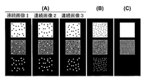
- FIG. 9 compares the effect of the processing by the moving average method and the processing to which the image processing method of the present invention is applied with three images obtained from spatially continuous positions as shown in FIG. The result is shown.
- (A) is three continuous images to be tested, one of which is a processing target, and the other images are also used for processing. That is, the continuous image 1 in FIG. 9 corresponds to the tomographic image B T ⁇ 1 , the continuous image 2 corresponds to the tomographic image B T , and the continuous image 3 corresponds to the tomographic image B T + 1 .
- (B) is an image obtained as a result of processing the continuous image 2 by the moving average method, and
- (C) is an image obtained as a result of processing the continuous image 2 by the image processing method of the present invention.
- Object (1 ') a structure that exists in all images and does not change in size, shape, or position (2), a structure that exists in all images, does not change in size or shape, but changes in position
- a moving average method that is, an average of luminance values of a total of three pixels, that is, a pixel of interest in a continuous image 2 and pixels in both adjacent continuous images 1 and 3 corresponding to the position of three consecutive images.
- a method of replacing the value with the luminance value of the target pixel was used.
- the advantage of the moving average method is that when the shape, size, and position of a structure are substantially the same in three consecutive images, only the noise can be removed while the structure of interest is maintained correctly.
- the problem is when at least one of the shape, size, brightness, and position changes in three consecutive images of the structure of interest, with particular attention only to the image of interest.
- the present example applies the image processing method of the present invention to three consecutive images, and the 26 pixels adjacent to the target pixel.
- the application of the present invention is extended from a plane to a space. Since the number of target adjacent pixels increases, the conditions of the luminance difference threshold and the non-applicable allowable number different from those in the first and second embodiments are determined and used in advance. Specifically, the image processing result was evaluated using 32 as the luminance difference threshold and 3 as the non-applicable allowable number.
- FIG. 9B the above-mentioned problems, that is, the occurrence of blur and the reflection of phantom were observed as expected in the moving average method.
- FIG. 9C the same structure as the structure in the image of interest was extracted without being affected by the structure of the adjacent image.
- FIG. 10 shows the results of comparing the effects of processing by the moving average method and processing to which the image processing method of the present invention is applied by preparing three consecutive images.
- (B) is an image obtained by processing the continuous image 2 by the moving average method
- (C) is an image obtained by processing the continuous image 2 by the image processing method of the present invention.
- the three continuous images there are structures having the same shape, size, color, and position, but the positions of the noise points are different in each image.
- the noise point is averaged with the value of the pixel at the same position in the other two images, the difference from the brightness of the structure is reduced, but the noise can be completely removed However, it remained as an identifiable noise point.
- FIG. 11 shows the effect when the image processing method of the present invention is applied to a single fundus optical coherence tomographic image (OCT image).
- 3 is an explanatory diagram prepared for comparing the method and the image processing method of the present invention.
- (A) is a pseudo-illustration image of a tomographic image to be processed
- (B) is an average value method
- (C) is a median method
- (D) is an image subjected to noise removal processing by the method of the present invention. Show.
- the tomographic image (A) several small structures with high brightness (white) are seen, and some noise points including white points and black points are scattered throughout the image.
- Examples 1 to 4 the principle and effect of the present invention have been described using relatively simple images.
- the OCT of the fundus of the eye to be examined is assumed as one of the actual uses of the present invention. Since there is an analysis of a high-intensity microstructure that uses a tomographic image as an application target, an image similar to that situation was created to confirm the effect of the image processing method of the present invention. Note that the high-luminance microstructure corresponds to a cross section of a blood vessel, a foreign body, or a cell containing a large amount of melanin.
- noise removal processing is performed on the single tomographic image as shown in FIG. 11A by the average value method, as shown in FIG. 11B, the luminance of the target structure is reduced or the contour is shifted (blurred). ) Occurs.
- noise removal processing by the median method is effective for noise removal (because taking the median makes it easier to take the same value as the adjacent pixel). ) Uniformity of luminance was observed, which influenced the shape of the structure of interest.
- noise removal processing is performed using the image processing method of the present invention, as shown in FIG. 11D, noise consisting of white points and black points is removed while maintaining the shape and brightness of the structure. I was able to. This reduces the possibility of misidentifying a white point as a structure and reduces the possibility of misidentifying the size and number of structures due to the division of the structure caused by the black spots generated in the structure. I can expect.
- the luminance difference threshold and the non-applicable allowable number are examined in advance so that noise can be appropriately removed, and the first luminance difference threshold and the second luminance difference threshold are set to 24, and the first non-applicable allowable number is set. 1 and the second non-applicable allowable number was 4.
- FIG. 12 is a pseudo image of three fundus optical coherence tomograms (OCT images) obtained from spatially continuous positions as shown in FIG. 2, and the effects of noise removal processing by the moving average method are shown.
- FIG. 10 is an explanatory diagram showing a result of comparing the effects of noise removal processing by the image processing method of the present invention.
- (A) is three continuous images to be processed. One of the images is a processing target, and other images are also used for processing. That is, the tomographic image 1 in FIG. 12A corresponds to the tomographic image B T-1 described above, the tomographic image 2 corresponds to the tomographic image B T , and the tomographic image 3 corresponds to the tomographic image B T + 1 .
- (B) shows a moving average method
- (C) shows an image resulting from noise removal processing of the pseudo image of (A) by the method of the present invention.
- some small structures with high brightness (white) are found, and some noise points including white points and black points are scattered throughout the image.
- noise removal processing is performed using the image processing method of the present invention, as shown in FIG. 12 (C), noise consisting of white points and black points is not changed without changing the shape and brightness of the structure of interest. It was possible to remove it efficiently.
- the luminance difference threshold value and the non-applicable allowable number were determined in advance so that noise can be appropriately removed.
- the same 24 as in the fifth embodiment is used as the first luminance difference threshold and the second luminance difference threshold.
- the first non-applicable allowable number is set to 3, 2 The permissible number is 12.
- the determination conditions (the luminance difference threshold and the non-applicable allowable number) applied in each embodiment described above vary depending on the type of image, the measurement condition, and the like, and thus must not necessarily be the numerical values shown in each embodiment. It is not a matter of necessity, but can be determined and determined in advance by appropriate examination.
- a luminance difference threshold and a non-applicable allowable number that are automatically applied based on an image to be processed may be calculated.
- a non-applicable allowable number may be determined in advance.
- the present invention can be used as a method for efficiently removing noise in image diagnosis using an image with a poor signal to noise ratio (S / N).
- S / N signal to noise ratio
- the shape and number of minute structures in an image with a poor S / N are not diagnosed.
- the present invention can be expected to be used as a powerful image noise removal method.
Landscapes
- Physics & Mathematics (AREA)
- General Physics & Mathematics (AREA)
- Engineering & Computer Science (AREA)
- Theoretical Computer Science (AREA)
- Image Processing (AREA)
- Image Analysis (AREA)
- Eye Examination Apparatus (AREA)
- Facsimile Image Signal Circuits (AREA)
Abstract
本発明の画像処理装置20は、注目画素の輝度値と、注目画素の周囲に位置する複数の隣接画素それぞれの輝度値との差分値をそれぞれ算出する算出手段31と、算出された差分値が所定の閾値以下である隣接画素の数を非該当隣接画素数としてカウントする計数手段32と、非該当隣接画素数が所定数以下である場合には、複数の隣接画素の輝度値の平均値をもって注目画素の輝度値を置き換える置換手段33と、を備える。本発明の画像処理装置、画像処理方法及び画像処理プログラムによれば、画像中の構造物の特徴を維持したまま、画像中のノイズを低減することができる。
Description
本発明は、ノイズを含む画像を処理してノイズを低減した画像を生成するための画像処理装置、画像処理方法及び画像処理プログラムに関する。
シグナルとノイズの比(S/N)が良好でない画像には白色点や黒色点からなるノイズが多く含まれる。これらのノイズは、例えば画像を分析・解析して何らかの情報を得るために行う画像処理の過程において、間違った分析・解析結果が導かれる原因となったり、得られた結果のばらつきを増大させる原因となったりする。特に医療分野において、観察部位の二次元画像や断層画像を得て画像診断を行う場合、異常とみなす注目する構造物は非常に小さかったり、不鮮明であったり、あるいは、幅が狭かったりする。そのような場合、ノイズ点が間違って着目する対象の構造物として抽出されてしまったり、ノイズ成分が着目する構造物を分断してしまうことにより、本来一つの構造物であったものを複数の構造物として認識させてしまったりする原因となる。そのため、いかにしてノイズを除去するかは画像処理の過程において非常に重要な課題となっている。
従来、単一の画像に対してノイズを低減すべく行う処理としては、注目画素周辺の画素に着目して平均値をとったり、あるいは、中央値をとったりする方法が広く用いられている。これは、これらの処理により白色点や黒色点の寄与が薄まり、結果的にその領域の平均値から大きく外れるノイズが除去されることになるためである。また、連続する複数枚の画像を処理する分野、例えば眼底断層画像を扱う分野においては、例えば特許文献1に開示されているように、隣接する二枚以上の画像間において同様に画素の平均値や中央値を用いて移動平均をとることによりノイズを低減する方法がとられてきた。
しかしながら、従来のこれらの方法では、画像中の注目画素の周辺情報を一律に平均化することから、画像中の構造物の輪郭をぼかしてしまったり、構造物の輝度を下げてしまったりする結果となり、注目する構造物と背景とのコントラストを下げてしまうばかりか、構造物の形、明るさ、色などの特徴そのものを損なってしまうという問題点があった。
また、断層画像などを扱う分野においては、上述のように注目する構造物の特徴を損なってしまうという問題点に加え、さらに次のような問題点もある。すなわち、連続する断層画像間の移動平均をとる方法では、複数の画像の画素を平均化することによりノイズと判断される画素を容易に除去することができ、滑らかな連続断層像を生成することはできるものの、連続する画像間で平均化処理をすることにより、注目する断層画像には含まれないがその前後の断層画像に含まれている構造物が処理後の注目する断層画像に映りこんでしまうという問題点があった。
本発明は、このような点に鑑みてなされたものであり、画像中の構造物の特徴を維持したまま、画像中のノイズを低減することができる画像処理装置、画像処理方法及び画像処理プログラムを提供することを目的とする。
上記目的を達成するために、第一に本発明は、注目画素の輝度値と、前記注目画素の周囲に位置する複数の隣接画素それぞれの輝度値との差分値をそれぞれ算出する算出手段と、算出された前記差分値が所定の閾値以下である前記隣接画素の数を非該当隣接画素数としてカウントする計数手段と、前記非該当隣接画素数が所定数以下である場合には、前記複数の隣接画素の輝度値の平均値をもって前記注目画素の輝度値を置き換える置換手段と、を備える画像処理装置を提供する(発明1)。
上記発明(発明1)によれば、単純に注目画素の輝度値を周辺画素(注目画素の周囲に位置する隣接画素)の輝度値を用いて平均化するのではなく、注目画素の輝度値と周辺画素の輝度値との差分値に基づいて注目画素が周辺画素よりも明らかに明るいか、又は暗いかを判定し、注目画素が白色点や黒色点からなるノイズであると判断される場合のみ、周辺画素の輝度値の平均値で注目画素の輝度値を置き換えるため、画像中のノイズのみを除去することができる。その結果、画像中に存在する特徴的な構造物の形、明るさ、色などの特徴を損なうことなく、ノイズの低減処理を行うことができる。
上記発明(発明1)においては、前記算出手段が、前記注目画素の輝度値から前記複数の隣接画素それぞれの輝度値を差し引いて求められる第1差分値と、前記複数の隣接画素それぞれの輝度値から前記注目画素の輝度値を差し引いて求められる第2差分値とをそれぞれ算出し、前記計数手段が、前記第1差分値が所定の第1閾値以下である前記隣接画素の数を第1非該当隣接画素数としてカウントするとともに、前記第2差分値が所定の第2閾値以下である前記隣接画素の数を第2非該当隣接画素数としてカウントし、前記置換手段が、前記第1非該当隣接画素数が第1の所定数以下であるか、または前記第2非該当隣接画素数が第2の所定数以下である場合には、前記複数の隣接画素全ての輝度値の平均値をもって前記注目画素の輝度値を置き換えてもよい(発明2)。
上記発明(1,2)においては、前記注目画像の存する画像が連続する複数の断層画像のうちの一の断層画像であり、前記複数の隣接画素が、前記一の断層画像及びその前後の断層画像において空間的に前記注目画素の周囲に位置する複数の隣接画素であってもよい(発明3)
上記発明(発明3)によれば、連続する断層画像を扱う場合においても注目する構造物の特徴を損なわず、かつ前後の断層画像中に含まれる構造物が処理後の注目する断層画像に映り込むこともなく、ノイズ低減処理を行うことができる。
第二に本発明は、注目画素の輝度値と、該注目画素の周囲に位置する複数の隣接画素それぞれの輝度値との差分値をそれぞれ算出する算出工程と、算出された前記差分値が所定の閾値以下である前記隣接画素の数を非該当隣接画素数としてカウントする計数工程と、前記非該当隣接画素数が所定数以下である場合には、前記複数の隣接画素の輝度値の平均値をもって前記注目画素の輝度値を置き換える置換工程と、を備える画像処理方法を提供する(発明4)。
上記発明(発明4)によれば、単純に注目画素の輝度値を周辺画素(注目画素の周囲に位置する隣接画素)の輝度値を用いて平均化するのではなく、注目画素の輝度値と周辺画素の輝度値との差分値に基づいて注目画素が周辺画素よりも明らかに明るいか、又は暗いかを判定し、注目画素が白色点や黒色点からなるノイズであると判断される場合のみ、周辺画素の輝度値の平均値で注目画素の輝度値を置き換えるため、画像中のノイズのみを除去することができる。その結果、画像中に存在する特徴的な構造物の形、明るさ、色などの特徴を損なうことなく、ノイズの低減処理を行うことができる。
上記発明(発明4)においては、前記算出工程において、前記注目画素の輝度値から前記複数の隣接画素それぞれの輝度値を差し引いて求められる第1差分値と、前記複数の隣接画素それぞれの輝度値から前記注目画素の輝度値を差し引いて求められる第2差分値とをそれぞれ算出し、前記計数工程において、前記第1差分値が所定の第1閾値以下である前記隣接画素の数を第1非該当隣接画素数としてカウントするとともに、前記第2差分値が所定の第2閾値以下である前記隣接画素の数を第2非該当隣接画素数としてカウントし、前記置換工程において、前記第1非該当隣接画素数が第1の所定数以下であるか、または前記第2非該当隣接画素数が第2の所定数以下である場合には、前記複数の隣接画素全ての輝度値の平均値をもって前記注目画素の輝度値を置き換えてもよい(発明5)。
上記発明(4,5)においては、前記注目画像の存する画像が連続する複数の断層画像のうちの一の断層画像であり、前記複数の隣接画像が、前記一の断層画像及びその前後の断層画像において空間的に前記注目画素の周囲に位置する複数の隣接画素であってもよい(発明6)。
上記発明(発明6)によれば、連続する断層画像を扱う場合においても注目する構造物の特徴を損なわず、かつ前後の断層画像中に含まれる構造物が処理後の注目する断層画像に映り込むこともなく、ノイズ低減処理を行うことができる。
第三に本発明は、コンピュータを発明1~3のいずれか1つに係る画像処理装置として機能させるための、あるいはコンピュータに発明4~6のいずれか1つに係る画像処理方法を実行させるための画像処理プログラムを提供する(発明7)。
本発明の画像処理装置、画像処理方法及び画像処理プログラムによれば、画像中の構造物の特徴を維持したまま、画像中のノイズを低減することができる。
以下、本発明の本実施形態を図面に基づいて詳細に説明する。ここでは、断層像差撮影装置により被検眼の眼底Eの断層画像を取得し、この断層画像からノイズを除去する例について説明するが、本発明における処理の対象となる画像は眼底断層画像に限定されるものでなく、他の種類の装置で他の対象を撮影した場合にも適用することができる。
図1は、被検眼眼底の断層画像を取得して画像処理するシステム全体を示すブロック図である。断層像撮影装置10は、被検眼の眼底の断層像を撮影する装置(OCT:Optical Coherence Tomography)であり、例えばフーリエドメイン方式で動作する。断層像撮影装置10は公知であるので、その詳細な説明は省略するが、断層像撮影装置10には、低コヒーレンス光源が設けられ、低コヒーレンス光源からの光が参照光と信号光に分割される。信号光は、図2に図示したように、眼底E上で、例えばX、Y方向にラスタースキャンされる。眼底Eで走査され反射された信号光は、参照ミラーで反射した参照光と重畳され干渉光を発生し、該干渉光に基づいて眼底の深度方向(Z方向)の情報を示すOCT信号が発生する。
画像処理装置20は、CPU、RAM、ROMなどで構成されたコンピュータで実現される制御部21を有し、制御部21は画像処理プログラムを実行することにより全体の画像処理を制御する。また、画像処理装置20には、断層画像形成部22が設けられる。
断層画像形成部22は、フーリエドメイン方式などの公知の解析方法を実行する専用の電子回路、または、前述のCPUが実行する画像処理プログラムにより実現され、断層像撮影装置10で生成されたOCT信号に基づいて、被検眼眼底の断層画像を形成する。
例えば、図2に示したように、眼底EがY方向にyN(N=1、2、・・・・・、n)の位置で、X方向にスキャンされた場合、当該スキャン時に複数回(m回)サンプリングが行われる。このX方向の各サンプリング時点でそれぞれZ方向の断層画像(Aスキャン画像)Ah(h=1、2、・・・・・、m)が取得され、これらのAスキャン画像Ahから断層画像BN(N=1、2、・・・・・、t)が形成される。Aスキャン画像は、例えば、X方向に1画素幅、Z方向にn画素の長さで格納されるので、断層画像BNはm×n画素の大きさをもつ画像となり、Bスキャン画像とも呼ばれる。
断層画像形成部22で形成されたt枚の断層画像BN、あるいはこれらt枚の断層画像BNから構築される3次元のボリューム画像は、例えば半導体メモリ、ハードディスク装置等により構成された記憶部23に格納される。記憶部23は、さらに上述した画像処理プログラムなども格納する。
画像処理装置20には、画像処理部30が設けられる。画像処理部30は、算出手段31、計数手段32、置換手段33を備えている。後述するように、算出手段31は、処理対象となる画像中の注目画素の輝度値と、当該注目画素の周囲に位置する複数の隣接画素それぞれの輝度値との差分値をそれぞれ算出し、計数手段32は、算出された差分値が所定の閾値(輝度差閾値)以下である隣接画素の数を非該当隣接画素数としてカウントし、置換手段33は、非該当隣接画素数が所定数(非該当許容数)以下である場合には、複数の隣接画素の輝度値の平均値をもって注目画素の輝度値を置き換える。画像処理部30における各手段あるいは各画像処理は、専用の電子回路を用いることにより、あるいは画像処理プログラムを実行することに実現される。
表示部24は、例えば、LCDなどのディスプレイ装置によって構成され、記憶部23に格納された断層画像、画像処理装置20で生成あるいは処理された画像、被験者に関する情報などの付随する情報などを表示する。
操作部25は、例えば、マウスやキーボード、操作ペン、ポインター、操作パネル等を有し、表示部24に表示された画像の選択、あるいは操作者が画像処理装置20などに指示を与えるために用いられる。
続いて、断層像撮影装置10により被検眼Eの眼底の断層像を撮影し、撮影した断層像を元に断層画像形成部22によって生成された被検眼眼底の断層画像中のノイズを、画像処理部30による画像処理により除去する流れを説明する。まず、得られたt枚の断層画像BNのうちの一枚を処理対象画像BTとして、この単一の処理対象画像BTからノイズを除去する流れを説明する。
処理対象画像BTは、図3の(A)に示すように、m×n画素の大きさをもつ画像である。この処理対象画像BTからノイズを除去する流れを図4に示す。なお、図4中のs101~s107が以下に述べる流れの説明におけるステップ101~107に相当する。図4に示す流れにおいて、まず算出手段31は、この処理対象画像BTにおいて注目する画素を注目画素Pとして一つ設定し、その注目画素Pの周囲に位置する画素、すなわち注目画素Pの上下左右に位置する画素と注目画素Pの四隅に接するように位置する画素の合計8個の画素を隣接画素pi(i=1~8)として設定する(ステップ101)。図3(B)に、処理対象画像BTの左から4列目、上から3行目に設定された注目画素Pと、その周囲に位置する8個の隣接画素piの関係を示す。
なお、処理対象画像BTにおいて注目画像Pを端部に設定する場合には必ずしも隣接画素が8個設定されるわけではなく、注目画素Pが処理対象画像BTにおいて端部に設定される場合、隣接画素はその注目画素の位置に合わせて適宜8個以内で設定されてよい。例えば注目画素が処理対象画像BTの左から1列目、上から3行目に設定された場合には、図3(C)に示すように、注目画素Pの上、下、右、右斜め上、右斜め下に位置する5個の画素が隣接画素として設定される。
また、処理する画像の種類やノイズ除去の目的等に応じて注目画素の上下左右に位置する4個のみを隣接画素として設定するようにしてもよいし、注目画素の上下左右に位置する画素と注目画素の四隅に接するように位置する8個の画素に加えて、更にその外側に位置する16個の画素を併せた24個の画素を隣接画素として設定する等、隣接画素の設定の方法を適宜変更してもよい。
続いて算出手段31は、注目画素Pの輝度値Dと、8つの隣接画素piの輝度値di(i=1~8)を処理対象画像BTの原画像データから取得する(ステップ102)。
注目画素Pの輝度値D及び隣接画素piの輝度値diを取得した後、算出手段31は、注目画素Pの輝度値Dから各隣接画素piの輝度値diを差し引いた第1差分値を、8個の隣接画素piのそれぞれについて算出する(ステップ103a)。この第1差分値は隣接画素の数だけ算出され、注目画素Pが白色点ノイズであるかどうかを推定するために用いられる。
続いて注目画素Pの白色点判定を行う。具体的には、計数手段32が、算出された第1差分値が、あらかじめ記憶部23に保存しておいた第1輝度差閾値PKT以下であるかどうかを比較し、第1輝度差閾値PKT以下であった隣接画素の数を第1非該当隣接画素数としてカウントする(ステップ104a)。すなわち、条件式:注目画素Pの輝度値D-隣接画素piの輝度値di≦PKTを満たす隣接画素の数が第1非該当隣接画素数となる。
第1非該当隣接画素数をカウントした後、置換手段33が、その第1非該当隣接画素数があらかじめ記憶部23に保存しておいた第1非該当許容数PFT以下であるかどうかを判定する(ステップ105a)。第1非該当隣接画素数が第1非該当許容数PFT以下であれば、注目画素Pは白色点ノイズであると判断される。
一方、第1非該当隣接画素数が第1非該当許容数PFT以下でなければ、算出手段31は、各隣接画素piの輝度値diから注目画素Pの輝度値Dを差し引いた第2差分値を、8個の隣接画素piのそれぞれについて算出する(ステップ103b)。この第2差分値も第1差分値同様に隣接画素の数だけ算出され、注目画素Pが黒色点ノイズであるかどうかを推定するために用いられる。
続いて注目画素Pの黒色点判定を行う。具体的には、計数手段32が、算出された第2差分値が、あらかじめ記憶部23に保存しておいた第2輝度差閾値HLT以下であるかどうかを比較し、第2輝度差閾値HLT以下であった隣接画素の数を第2非該当隣接画素数としてカウントする(ステップ104b)。すなわち、条件式:隣接画素piの輝度値di-注目画素Pの輝度値D≦HLTを満たす隣接画素の数が第2非該当隣接画素数となる。
第2非該当隣接画素数をカウントした後、置換手段33が、その第2非該当隣接画素数があらかじめ記憶部23に保存しておいた第2非該当許容数HFT以下であるかどうかを判定する(ステップ105b)。第2非該当隣接画素数が第2非該当許容数HFT以下であれば、注目画素Pは黒色点ノイズであると判断される。
ステップ105a及び105bの判定の結果、注目画素Pが白色点ノイズであると判断された場合(第1非該当隣接画素数が第1非該当許容数PFT以下である場合)及び注目画素Pが黒色点ノイズであると判断された場合(第2非該当隣接画素数が第2非該当許容数HFT以下である場合)、置換手段33は、各隣接画素piの輝度値diの平均値を算出する(ステップ106)。そして、算出した平均値をもって注目画素Pの輝度値を置き換えた画像を生成し(ステップ107)、記憶部23に保存する。ステップ105aの判定の結果、第1非該当隣接画素数が第1非該当許容数PFT以下ではなく、かつステップ105bの判定の結果、第2非該当隣接画素数が第2非該当許容数HFT以下ではない場合、注目画素Pの輝度値は平均値に置き換えることなく、そのままとする。
上述の処理を、処理対象画像BTにおいて、例えば左上端の画素から順に全ての画素を注目画素として設定しながら繰り返し、最終的に処理対象画像BTの全体においてノイズ除去処理を行った画像が生成される。
このように本発明は、処理対象となる画像中の注目する画素と、その周囲に位置する隣接画素とを比較して、注目画素の輝度値が隣接画素よりも所定の値以上に明るい場合、あるいは暗い場合には隣接画素の平均値と置き換えるものである。置き換えに用いる隣接画素と注目画素の輝度の差を大きくする、すなわち上述した第1輝度差閾値及び第2輝度差閾値を大きく設定すれば置き換えられる注目画素の数は減り、逆に小さく設定すれば置き換えられる注目画素の数が増加する。
一方、置き換えの判定において、注目画素が全ての隣接画素よりも所定値以上に明るいかどうか、あるいは、注目画素が全ての隣接画素よりも所定値以上に暗いかどうかという、最も厳格な判定式を用いることもできる。この場合、上述の第1非該当許容数や第2非該当許容数を0とすることにより、注目画素が全ての隣接画素よりも所定値以上に明るい、あるいは、注目画素が全ての隣接画素よりも所定値以上に暗い場合にのみ、注目画素の輝度値を隣接画素の輝度値の平均値で置き換えるという処理を行うことになる。第1非該当許容数や第2非該当許容数を小さくするほど平均値に置換される注目画素の個数は減り、第1非該当許容数や第2非該当許容数を増やすにしたがって置換される注目画素の数が増加する。
第1輝度差閾値及び第2輝度差閾値は同じ値を用いてもよいし、個別に異なる数値を設定してもよい。また、第1非該当許容数及び第2非該当許容数も同じ値を用いてもよいし、個別に異なる数値を設定してもよい。これらのあらかじめ記憶部23に保存しておく条件値は、画像の質や抽出したい構造物の性状(形、明るさ、大きさ等)によって、最適な値をあらかじめ検討しておいて適用させることができる。
本実施形態に係る画像処理装置及び画像処理方法によれば、単純に注目画素の輝度値を周辺画素(注目画素の周囲に位置する隣接画素)の輝度値を用いて平均化するのではなく、注目画素の輝度値と周辺画素の輝度値との差分値に基づいて注目画素が周辺画素よりも明らかに明るいか、又は暗いかを判定し、注目画素が白色点や黒色点からなるノイズであると判断される場合のみ、周辺画素の輝度値の平均値で注目画素の輝度値を置き換えるため、画像中のノイズのみを除去することができる。その結果、画像中に存在する特徴的な構造物の形、明るさ、色などの特徴を損なうことなく、ノイズの低減処理を行うことができる。
なお、本実施形態では断層像撮影装置10により取得した断層画像BNのうちの一枚を処理対象画像BTとしたが、走査型レーザー検眼鏡(SLO:Scanning Laser Ophthalmoscope)により取得した眼底平面画像を処理対象画像としてここまでと同様の画像処理を行い、ノイズを除去することもできる。
<第1変形例>
ここまで単一の処理対象画像BTからノイズを除去する流れを説明したが、以下においては、図2に示すように空間的に連続しているところから得られたt枚の断層画像BNのうちの一枚を処理対象画像BTとして、その前後の断層画像BT-1及び断層画像BT+1も併せて用いて、注目画素及び隣接画素を設定する方法を説明する。断層画像BT-1及び断層画像BT+1は、図2に示したY方向において処理対象画像BTに連続する断層画像であり、処理対象画像BTと同様にm×n画素の大きさをもつ画像である。本変形例における画像処理に用いられる断層像撮影装置10や画像処理装置20は、前述のものと同じ構成を有するため、詳細な説明は省略するが、断層画像BT-1、処理対象画像BT及び断層画像BT+1はいずれも記憶部23に格納されている。
ここまで単一の処理対象画像BTからノイズを除去する流れを説明したが、以下においては、図2に示すように空間的に連続しているところから得られたt枚の断層画像BNのうちの一枚を処理対象画像BTとして、その前後の断層画像BT-1及び断層画像BT+1も併せて用いて、注目画素及び隣接画素を設定する方法を説明する。断層画像BT-1及び断層画像BT+1は、図2に示したY方向において処理対象画像BTに連続する断層画像であり、処理対象画像BTと同様にm×n画素の大きさをもつ画像である。本変形例における画像処理に用いられる断層像撮影装置10や画像処理装置20は、前述のものと同じ構成を有するため、詳細な説明は省略するが、断層画像BT-1、処理対象画像BT及び断層画像BT+1はいずれも記憶部23に格納されている。
本変形例においては、処理対象画像BTにおいて注目する画素を注目画素Qとして一つ設定し、当該処理対象画像BT及びその前後の断層画像BT-1及び断層画像BT+1において空間的に注目画素の周囲に位置する合計26個の画素を隣接画素qi(i=1~26)として設定する。
すなわち、本変形例における隣接画素qiは、処理対象画像BTにおいて注目画素Qの上下左右に位置する画素及び注目画素の四隅に接するように位置する画素の合計8個の画素に加え、断層画像BT-1及び断層画像BT+1を処理対象画像BTに並べたときに空間的に注目画素Qの周囲に位置することとなる合計18個の画素を含めた合計26個の画素である。図5に、処理対象画像BTの左から4列目、上から3行目に設定された注目画素Qと、当該処理対象画像BT及びその前後の断層画像BT-1及び断層画像BT+1において空間的に注目画素Qの周囲に位置する26個の隣接画素qiの関係を示す。また、処理対象画像BT及びその前後の断層画像BT-1及び断層画像BT+1を並べた状態から注目画素Qと隣接画素qiだけを切り出した状態を図6に示す。
なお、処理対象画像BTにおいて注目画素Qを端部に設定する場合には必ずしも隣接画素が26個設定されるわけではなく、注目画素Qが処理対象画像BTにおいて端部に設定される場合、隣接画素はその注目画素の位置に合わせて適宜26個以内で設定されてよい。また、前後に連続する断層画像が存在しない場合も隣接画素はその注目画素の位置に合わせて適宜26個以内で設定されてよい。さらに、処理する画像の種類やノイズ除去の目的等に応じて隣接画素の設定の方法を適宜変更してもよい。
このように注目画素Qと隣接画素qiを設定した場合にも、図4に示した流れに沿って、画像処理部30による画像処理によりノイズを除去することができる。画像処理の流れは単一の処理対象画像BTからノイズを除去する流れと同様であるため省略する。
このように連続する断層画像を扱う場合においても、本実施形態に係る画像処理装置及び画像処理方法を適用することにより、画像中のノイズのみを除去することができる。その結果、画像中に存在する特徴的な構造物の形、明るさ、色などの特徴を損なうことなく、かつ前後の断層画像中に含まれる構造物が処理後の注目する断層画像に映り込むこともなく、ノイズ低減処理を行うことができる。
<第2変形例>
ここまでは断層像撮影装置10により取得した断層画像BNを処理対象としてきたが、OCTアンギオグラフィ(OCTA:Optical Coherence Tomography Angiography)を用いて生成された網膜血管の正面画像(En Face画像)に対して画像処理を行ない、当該画像からノイズを除去することもできる。OCTアンギオグラフィは、蛍光剤を使用せずに血管造影のような画像を生成するものであり、上記実施形態において説明した断層像撮影装置10を用いて被検眼の眼底Eの同一箇所を連続で複数枚撮影し、取得された数msの時間差断層画像(Bスキャン画像)における変化を血流変化とみなして正面画像を生成する。
ここまでは断層像撮影装置10により取得した断層画像BNを処理対象としてきたが、OCTアンギオグラフィ(OCTA:Optical Coherence Tomography Angiography)を用いて生成された網膜血管の正面画像(En Face画像)に対して画像処理を行ない、当該画像からノイズを除去することもできる。OCTアンギオグラフィは、蛍光剤を使用せずに血管造影のような画像を生成するものであり、上記実施形態において説明した断層像撮影装置10を用いて被検眼の眼底Eの同一箇所を連続で複数枚撮影し、取得された数msの時間差断層画像(Bスキャン画像)における変化を血流変化とみなして正面画像を生成する。
具体的には、被検眼の眼底Eの同一箇所を連続で複数枚撮影したBスキャン画像群に対し、公知の変化検出方法、例えば、OMAG(Optical Microangiography)法や、SSADA(Split-spectrum Amplitude-decorrelation Angiography)法等を適用して一の血流断層画像を生成する。これを観察対象領域に対してY方向にスキャン位置を変えながら繰り返し、得られた連続する複数の血流断層画像から一つの三次元データセットを生成する。すなわち、三次元データセットは被検眼の眼底Eの観察対象領域を立体的にモデル化したデータである。
Bスキャン画像群を構成するそれぞれのBスキャン画像が図2におけるXZ平面の断層画像である場合、当該Bスキャン画像群から生成される血流断層画像もXZ平面の断層画像となるが、三次元データセットから今度はZ方向に連続する複数のXY平面の断層画像として血流断層画像を生成する。このZ方向に連続する複数のXY平面の血流断層画像を重層することにより網膜血管の正面画像が生成される。
重層される複数のXY平面の血流断層画像のうちの一枚の血流断層画像を第1変形例における処理対象画像BTとし、その血流断層画像を挟むように重なる前後の血流断層画像を断層画像BT-1及び断層画像BT+1とすれば、前述の第1変形例において説明したものと同様の画像処理方法をOCTアンギオグラフィにより生成された網膜血管の正面画像に適用することができ、当該正面画像中のノイズのみを除去することができる。
以上、本発明に係る画像処理装置及び画像処理方法について図面に基づいて説明してきたが、本発明は上記実施形態に限定されることはなく、種々の変更実施が可能である。
本発明に係る画像処理装置及び画像処理方法の利点をよりわかりやすく説明すべく、上記本発明の実施形態に示した画像処理装置及び画像処理方法を実際の画像に適用した実施例を従来法によるノイズ除去と比較しながら以下に説明する。
<実施例1>
図7は、画像中のノイズを除去する従来法である平均値法及び中央値法と、本発明の画像処理方法とを比較するために用意した説明図であり、(A)はノイズ点を含む簡単な構造物の図、(B)は平均値法、(C)は中央値法、(D)は本発明の方法でノイズ除去処理した画像を示す。
図7は、画像中のノイズを除去する従来法である平均値法及び中央値法と、本発明の画像処理方法とを比較するために用意した説明図であり、(A)はノイズ点を含む簡単な構造物の図、(B)は平均値法、(C)は中央値法、(D)は本発明の方法でノイズ除去処理した画像を示す。
図7(A)は本発明の効果を一般的なノイズ除去方法と比較するために、簡単な正方形の注目構造を含む試験画像を用意したものであり、画像の画素は黒色が0、白色が255、灰色は128という輝度値を持つようにしてある。正方形の注目構造は画像の上から三つ並んでおり、それぞれ白色、灰色、黒色の背景を持たせ、背景が白色の場合は黒色のノイズ点が、背景が黒色の場合は白色のノイズ点が、背景が灰色の場合は同数の白色と黒色のノイズ点が含まれている。画像の各画素について左上から水平方向に注目画素を移動していき、右下に到達するまで全ての画素に対して次のような画像処理を施した。
一つ目は、注目画素を含む8近傍9画素の平均値を求め、その平均値を注目画素と置き換える方法であり、平均値法と呼ぶ。二つ目は、注目画素を含む8近傍9画素を輝度の小さい方から昇順に並べ替え、5番目の輝度を持つ画素を注目画素と置き換える方法であり、中央値法と呼ぶ。三つ目は、本発明の画像処理方法であり、すなわち、注目画素と隣接8画素を比較し、注目画素の輝度値が隣接画素の輝度値に比べて既定の値以上に大きい場合、あるいは、小さい場合に隣接8画素の平均値を求め、注目画素と置き換える方法である。
図7(B)に示すように、平均値法ではノイズ点を周辺画素と平均化してぼかすため、当初存在していた周辺画素との大きな輝度の差は減少したものの、ノイズ点周辺の画素の値に影響して変化させてしまった。また同様に、対象形状の輪郭もぼかしてしまうため、注目する構造物の形状を維持し、且つ、ノイズを低減するという目的には使用することができなかった。一方、図7(C)に示すように、中央値法ではノイズ点を除去する点では優れた効果があるものの、対象形状の頂点部分を欠損してしまっている。これは、注目する構造物の角や先端部分では8近傍9画素に占める構造物由来の画素は少数派になってしまい、大多数を占める非構造物の画素が中央値として選定されてしまうためである。
続いて、本発明の画像処理方法において白色点検出用に第1輝度差閾値を48、第1非該当許容数を1と設定するとともに、黒色点検出用に第2輝度差閾値を6、第2非該当許容数を4と設定して画像処理結果を評価したところ、図7(D)に示すように、本発明の画像処理方法では完全にノイズを除去し、且つ、形状を正確に維持することができた。
<実施例2>
図8は、画像中での着目構造物を想定して、複雑な形状を含む画像に対して平均値法及び中央値法と、本発明の画像処理方法とによる処理の効果を比較するために用意した説明図であり、(A)は複雑な形状を含む試験画像、(B)は平均値法、(C)は中央値法、(D)は本発明の方法で画像処理した画像を示す。複雑形状としては輝度に濃淡がある構造物(A-上)、細線を結合させた構造物(A-中)、ならびに、突起がある構造物である(A-下)。これらの形状にはノイズ点は含まれておらず、それぞれのノイズ除去法がどのように構造物の形状に影響を与えるかを明らかにすることを目的とした。
図8は、画像中での着目構造物を想定して、複雑な形状を含む画像に対して平均値法及び中央値法と、本発明の画像処理方法とによる処理の効果を比較するために用意した説明図であり、(A)は複雑な形状を含む試験画像、(B)は平均値法、(C)は中央値法、(D)は本発明の方法で画像処理した画像を示す。複雑形状としては輝度に濃淡がある構造物(A-上)、細線を結合させた構造物(A-中)、ならびに、突起がある構造物である(A-下)。これらの形状にはノイズ点は含まれておらず、それぞれのノイズ除去法がどのように構造物の形状に影響を与えるかを明らかにすることを目的とした。
図8(B)に示すように、平均値法ではいずれの形状においても輪郭がぼやけ、形状の輝度が大幅に低下した。特に構造物中の細線状部位、あるいは、先端部位において注目画素を設定すると、その隣接画素においては構造物周辺の低輝度背景画素が多数を占めるため、平均化により構造物の情報が大きく損なわれた。一方、図8(C)に示すように、中央値法では形状の輪郭がぼやけることや、輝度が低下することはなかったものの、形状中の構造物中の細線状部位や先端部位は全く抽出されず、形状は試験画像の原型をとどめていなかった。細線を結合させた構造物(A-中)や突起がある構造物である(A-下)では、これらの部分が抽出されないことにより、複数の分断物として抽出された。
これに対して本発明の画像処理方法では、実施例1で予備検討して決定した輝度差閾値及び非該当許容数を用いた場合、図8(D)に示すように、先端構造部分で若干の抽出漏れが観察されたものの、他の方法と比べて形状を高く維持したまま構造物を抽出することができた。すなわち、実施例1と併せて考えると、本発明の画像処理方法によれば、抽出したい構造物の形状を高く維持したまま、ノイズ除去を行えることが示されている。
<実施例3>
図9は、図2に示すように空間的に連続しているところから得られた3枚の画像で、移動平均法による処理と本発明の画像処理方法を適用した処理との効果を比較した結果を示すものである。(A)は試験対象とする3枚の連続画像で、そのうちの一枚の画像を処理対象として、その他の画像も併せて用いて処理する。つまり、図9の連続画像1が前述の断層画像BT-1に相当し、連続画像2が断層画像BT、連続画像3が断層画像BT+1にそれぞれ相当する。(B)は移動平均法で連続画像2を処理した結果の画像、(C)は本発明の画像処理方法で連続画像2を処理した結果の画像である。
図9は、図2に示すように空間的に連続しているところから得られた3枚の画像で、移動平均法による処理と本発明の画像処理方法を適用した処理との効果を比較した結果を示すものである。(A)は試験対象とする3枚の連続画像で、そのうちの一枚の画像を処理対象として、その他の画像も併せて用いて処理する。つまり、図9の連続画像1が前述の断層画像BT-1に相当し、連続画像2が断層画像BT、連続画像3が断層画像BT+1にそれぞれ相当する。(B)は移動平均法で連続画像2を処理した結果の画像、(C)は本発明の画像処理方法で連続画像2を処理した結果の画像である。
3枚の連続画像においては、連続画像1にのみに存在し、連続画像2には含まれていない構造物(1)、連続画像3にのみ存在し、連続画像2には含まれていない構造物(1’)、全ての画像中に存在し、大きさ、形、位置ともに変化しない構造物(2)、全ての画像中に存在し、大きさ及び形は変化しないが位置が変化する構造物(3)、全ての画像中に存在し、中心座標は変化しないが大きさが変化する構造物(4)が含まれている。ノイズ点は含まれていない。
まず、従来法として移動平均法、すなわち、連続する三つの画像について、連続画像2中の注目画素とその位置に相当する両隣の連続画像1及び3中の画素、合計3画素の輝度値の平均値を注目画素の輝度値として置き換える方法を用いた。移動平均法の利点は連続する三つの画像で構造物の形、大きさ、位置がほぼ同じ場合、注目する構造物が正しく維持されつつ、ノイズのみが除去できることである。一方、問題となるのは、注目する構造物が連続する3画像中で、形、大きさ、輝度、位置の少なくとも1つ以上が変化する場合であり、特に、注目する画像にのみ着目している構造物がある場合や、構造物の大きさが変化する場合、構造物の位置が移動する場合には、隣接画像との平均化により構造物が重ならない部分での輝度の大幅な低下や構造のボケが発生する。また、注目している画像中には存在しない構造物が隣接する他の少なくとも一枚の画像中に存在する場合、本来、注目している画像中には観察されないはずの構造物が他の画像から影(ファントム)として映り込んでしまい、間違った構造物識別につながるおそれがある。
平面を対象として注目画素の隣接8画素を対象としていた実施例1及び2と異なり、本実施例では本発明の画像処理方法を三枚の連続する画像に適用して、注目画素の隣接26画素と注目画素とを比較する方法としており、すなわち本発明の適用を平面から空間へと拡張している。対象とする隣接画素数が増加するため、あらかじめ実施例1及び2とは異なった輝度差閾値及び非該当許容数の条件を決定して用いた。具体的には、輝度差閾値として32を用い、非該当許容数を3として画像処理結果を評価した。
図9(B)に示すように、移動平均法では予期していたように前述の問題点、つまりボケの発生とファントムの映り込みが見受けられたが、本発明の画像処理方法では、図9(C)に示すように、隣接する画像の構造物の影響を受けることなく、注目する画像中の構造物と同一のものが抽出された。
<実施例4>
図10は、連続する3枚の画像を用意して、移動平均法による処理と本発明の画像処理方法を適用した処理との効果を比較した結果を示すものであり、(A)は試験対象とする3枚の連続画像、(B)は移動平均法で連続画像2を処理した結果の画像、(C)は本発明の画像処理方法で連続画像2を処理した結果の画像である。3枚の連続画像においては、形、大きさ、色、ならびに、位置が同一の構造物が存在しているが、それぞれの画像でノイズ点の位置が異なっている。
図10は、連続する3枚の画像を用意して、移動平均法による処理と本発明の画像処理方法を適用した処理との効果を比較した結果を示すものであり、(A)は試験対象とする3枚の連続画像、(B)は移動平均法で連続画像2を処理した結果の画像、(C)は本発明の画像処理方法で連続画像2を処理した結果の画像である。3枚の連続画像においては、形、大きさ、色、ならびに、位置が同一の構造物が存在しているが、それぞれの画像でノイズ点の位置が異なっている。
構造物の形、輝度、位置が3枚の連続画像において共通であるため、移動平均法を適用した場合においても、図10(B)に示すように、構造物そのもののボケやファントムの映り込みは発生しなかったが、ノイズ点は他の2枚の画像の同一位置の画素の値と平均化されるため、構造物が持つ輝度との差は縮まったものの完全にノイズが除去するには至らず、識別可能なノイズ点として残存した。
これに対し、実施例1の条件値を用いて本発明の画像処理方法を適用したところ、図10(C)に示すように、ノイズのほぼ全てを構造物の輝度と識別が困難な程度に減弱することができた。
<実施例5>
図11は、1枚の眼底光干渉断層像(OCT像)に本発明の画像処理方法を適用した場合の効果を示すため、画像中のノイズを除去する従来法である平均値法及び中央値法と、本発明の画像処理方法とを比較するために用意した説明図である。(A)は処理対象とする断層画像を擬似的にイラスト化した画像、(B)は平均値法、(C)は中央値法、(D)は本発明の方法でノイズ除去処理した画像を示す。(A)の断層画像には輝度が高い(白色の)小さな構造物がいくつか見受けられるとともに、白色点や黒色点からなるノイズ点が画像全体にわたっていくつか散見される。
図11は、1枚の眼底光干渉断層像(OCT像)に本発明の画像処理方法を適用した場合の効果を示すため、画像中のノイズを除去する従来法である平均値法及び中央値法と、本発明の画像処理方法とを比較するために用意した説明図である。(A)は処理対象とする断層画像を擬似的にイラスト化した画像、(B)は平均値法、(C)は中央値法、(D)は本発明の方法でノイズ除去処理した画像を示す。(A)の断層画像には輝度が高い(白色の)小さな構造物がいくつか見受けられるとともに、白色点や黒色点からなるノイズ点が画像全体にわたっていくつか散見される。
実施例1~4においては比較的簡単な画像を用いて本発明の原理と効果を説明してきたが、本実施例においては本発明の実際の用途の一つとして想定される被検眼眼底のOCT断層画像を適用対象とした高輝度微小構造物の解析があるので、その状況に似た画像を作成して本発明の画像処理方法の効果を確認した。なお、高輝度の微小構造物は血管の断面であったり、異物であったり、あるいは、メラニンを多く含む細胞がこれに該当する。
図11(A)に示すような単一の断層画像に対して平均値法によりノイズ除去処理をすると、図11(B)に示すように、注目構造物の輝度の低下や輪郭のズレ(ボケ)が発生する。また、図11(C)に示すように、中央値法によりノイズ除去処理をすると、ノイズ除去には効果が認められるものの、(中央値をとることにより隣接画素と同じ値をとりやすくなるために)輝度の画一化が認められ、それに起因して注目構造物の形状に影響を与えた。
一方、本発明の画像処理方法を用いてノイズ除去処理をすると、図11(D)に示すように、構造物の形状及び輝度を維持したまま、白色点や黒色点からなるノイズを除去することができた。これにより、白色点を構造物と誤認する可能性を低下させ、構造物中に発生した黒色点がもたらす構造物の分断により構造物の大きさや数を誤認してしまう可能性を低下させることが期待できる。
なお、本実施例においては、適切にノイズが除去できるようにあらかじめ輝度差閾値及び非該当許容数を検討し、第1輝度差閾値及び第2輝度差閾値を24、第1非該当許容数を1、第2非該当許容数を4とした。
<実施例6>
図12は、図2に示すように空間的に連続しているところから得られた3枚の眼底光干渉断層像(OCT像)の擬似画像であり、移動平均法によるノイズ除去処理の効果と、本発明の画像処理方法によるノイズ除去処理の効果を比較した結果を示す説明図である。(A)は処理対象とする3枚の連続画像で、そのうちの一枚の画像を処理対象として、その他の画像も併せて用いて処理する。つまり、図12(A)の断層画像1が前述の断層画像BT-1に相当し、断層画像2が断層画像BT、断層画像3が断層画像BT+1にそれぞれ相当する。(B)は移動平均法、(C)は本発明の方法で(A)の擬似画像をノイズ除去処理した結果の画像を示す。(A)の3枚の断層画像には輝度が高い(白色の)小さな構造物がいくつか見受けられるとともに、白色点や黒色点からなるノイズ点が画像全体にわたっていくつか散見される。
図12は、図2に示すように空間的に連続しているところから得られた3枚の眼底光干渉断層像(OCT像)の擬似画像であり、移動平均法によるノイズ除去処理の効果と、本発明の画像処理方法によるノイズ除去処理の効果を比較した結果を示す説明図である。(A)は処理対象とする3枚の連続画像で、そのうちの一枚の画像を処理対象として、その他の画像も併せて用いて処理する。つまり、図12(A)の断層画像1が前述の断層画像BT-1に相当し、断層画像2が断層画像BT、断層画像3が断層画像BT+1にそれぞれ相当する。(B)は移動平均法、(C)は本発明の方法で(A)の擬似画像をノイズ除去処理した結果の画像を示す。(A)の3枚の断層画像には輝度が高い(白色の)小さな構造物がいくつか見受けられるとともに、白色点や黒色点からなるノイズ点が画像全体にわたっていくつか散見される。
図12(A)に示すような連続した3枚の画像に対して移動平均法でノイズ除去処理をすると、図12(B)に示すように、構造物のボケやファントムの映り込みが発生していることが確認できた。
一方、本発明の画像処理方法を用いてノイズ除去処理をすると、図12(C)に示すように、注目する構造物の形や輝度を変化させることなく、白色点や黒色点からなるノイズを効率よく除去することが可能であった。
なお、本実施例においては、連続する3枚の画像を対象として空間座標における隣接する画素(3×3×3-1=26画素)の輝度値から注目画素がノイズであるかどうかを判定しており、実施例5と同様に、適切にノイズが除去できるようにあらかじめ輝度差閾値及び非該当許容数を検討して決定した。具体的には、第1輝度差閾値及び第2輝度差閾値には実施例5と同じ24を用いたが、対象とする隣接画素の数が増えるため、第1非該当許容数を3、第2非該当許容数を12とした。
以上説明した各実施例において適用した本発明の判定条件(輝度差閾値及び非該当許容数)は、画像の種類や測定条件などによって異なってくるため、必ずしも各実施例において示された数値でなければならないというものではなく、あらかじめ適切な検討により決定して決めることができる。また、処理対象の画像に基づいて自動的に適用する輝度差閾値及び非該当許容数を算出するようにしてもよいし、画像処理装置の特性を考慮して、装置毎に異なる輝度差閾値及び非該当許容数をあらかじめ定めておいてもよい。
本発明はシグナルとノイズの比(S/N)が良好でない画像を用いる画像診断においてノイズを効率よく除去する方法として利用することが可能である。特に、強力な光源を照明光として利用することが困難な眼底画像診断、および、眼底断層像診断においてはS/Nが不良の画像中の微小な構造物の形状、ならびに、個数を診断しなくてはならないケースが多いため、本発明は強力な画像ノイズ除去法として利用できることが期待できる。
10 断層像撮影装置
20 画像処理装置
21 制御部
22 断層画像形成部
23 記憶部
24 表示部
25 操作部
30 画像処理部
31 算出手段
32 計数手段
33 置換手段
20 画像処理装置
21 制御部
22 断層画像形成部
23 記憶部
24 表示部
25 操作部
30 画像処理部
31 算出手段
32 計数手段
33 置換手段
Claims (7)
- 注目画素の輝度値と、前記注目画素の周囲に位置する複数の隣接画素それぞれの輝度値との差分値をそれぞれ算出する算出手段と、
算出された前記差分値が所定の閾値以下である前記隣接画素の数を非該当隣接画素数としてカウントする計数手段と、
前記非該当隣接画素数が所定数以下である場合には、前記複数の隣接画素の輝度値の平均値をもって前記注目画素の輝度値を置き換える置換手段と、を備える画像処理装置。 - 前記算出手段が、前記注目画素の輝度値から前記複数の隣接画素それぞれの輝度値を差し引いて求められる第1差分値と、前記複数の隣接画素それぞれの輝度値から前記注目画素の輝度値を差し引いて求められる第2差分値とをそれぞれ算出し、
前記計数手段が、前記第1差分値が所定の第1閾値以下である前記隣接画素の数を第1非該当隣接画素数としてカウントするとともに、前記第2差分値が所定の第2閾値以下である前記隣接画素の数を第2非該当隣接画素数としてカウントし、
前記置換手段が、前記第1非該当隣接画素数が第1の所定数以下であるか、または前記第2非該当隣接画素数が第2の所定数以下である場合には、前記複数の隣接画素全ての輝度値の平均値をもって前記注目画素の輝度値を置き換えることを特徴とする、請求項1に記載の画像処理装置。 - 前記注目画像の存する画像が連続する複数の断層画像のうちの一の断層画像であり、
前記複数の隣接画素が、前記一の断層画像及びその前後の断層画像において空間的に前記注目画素の周囲に位置する複数の隣接画素であることを特徴とする、請求項1又は2に記載の画像処理装置。 - 注目画素の輝度値と、該注目画素の周囲に位置する複数の隣接画素それぞれの輝度値との差分値をそれぞれ算出する算出工程と、
算出された前記差分値が所定の閾値以下である前記隣接画素の数を非該当隣接画素数としてカウントする計数工程と、
前記非該当隣接画素数が所定数以下である場合には、前記複数の隣接画素の輝度値の平均値をもって前記注目画素の輝度値を置き換える置換工程と、を備える画像処理方法。 - 前記算出工程において、前記注目画素の輝度値から前記複数の隣接画素それぞれの輝度値を差し引いて求められる第1差分値と、前記複数の隣接画素それぞれの輝度値から前記注目画素の輝度値を差し引いて求められる第2差分値とをそれぞれ算出し、
前記計数工程において、前記第1差分値が所定の第1閾値以下である前記隣接画素の数を第1非該当隣接画素数としてカウントするとともに、前記第2差分値が所定の第2閾値以下である前記隣接画素の数を第2非該当隣接画素数としてカウントし、
前記置換工程において、前記第1非該当隣接画素数が第1の所定数以下であるか、または前記第2非該当隣接画素数が第2の所定数以下である場合には、前記複数の隣接画素全ての輝度値の平均値をもって前記注目画素の輝度値を置き換えることを特徴とする、請求項4に記載の画像処理方法。 - 前記注目画像の存する画像が連続する複数の断層画像のうちの一の断層画像であり、
前記複数の隣接画素が、前記一の断層画像及びその前後の断層画像において空間的に前記注目画素の周囲に位置する複数の隣接画素であることを特徴とする、請求項4又は5に記載の画像処理方法。 - コンピュータを請求項1~3のいずれか1項に記載の画像処理装置として機能させるための、あるいはコンピュータに請求項4~6のいずれか1項に記載の画像処理方法を実行させるための画像処理プログラム。
Priority Applications (1)
| Application Number | Priority Date | Filing Date | Title |
|---|---|---|---|
| JP2018546351A JPWO2018074459A1 (ja) | 2016-10-18 | 2017-10-17 | 画像処理装置、画像処理方法及び画像処理プログラム |
Applications Claiming Priority (2)
| Application Number | Priority Date | Filing Date | Title |
|---|---|---|---|
| JP2016-204643 | 2016-10-18 | ||
| JP2016204643 | 2016-10-18 |
Publications (1)
| Publication Number | Publication Date |
|---|---|
| WO2018074459A1 true WO2018074459A1 (ja) | 2018-04-26 |
Family
ID=62018744
Family Applications (1)
| Application Number | Title | Priority Date | Filing Date |
|---|---|---|---|
| PCT/JP2017/037500 Ceased WO2018074459A1 (ja) | 2016-10-18 | 2017-10-17 | 画像処理装置、画像処理方法及び画像処理プログラム |
Country Status (2)
| Country | Link |
|---|---|
| JP (1) | JPWO2018074459A1 (ja) |
| WO (1) | WO2018074459A1 (ja) |
Cited By (3)
| Publication number | Priority date | Publication date | Assignee | Title |
|---|---|---|---|---|
| CN112401913A (zh) * | 2019-08-21 | 2021-02-26 | 株式会社日立制作所 | 医用图像处理装置以及医用图像处理方法 |
| CN114387174A (zh) * | 2021-12-02 | 2022-04-22 | 广东唯仁医疗科技有限公司 | 一种octa图像降噪方法、电子设备及存储介质 |
| EP4283558A4 (en) * | 2021-01-22 | 2025-04-16 | Logic and Design Co., Ltd. | IMAGE PROCESSING METHODS |
Citations (3)
| Publication number | Priority date | Publication date | Assignee | Title |
|---|---|---|---|---|
| JP2006280682A (ja) * | 2005-04-01 | 2006-10-19 | Hitachi Omron Terminal Solutions Corp | ノイズ検出機能を備えた画像診断支援方法 |
| WO2014112611A1 (ja) * | 2013-01-21 | 2014-07-24 | 興和株式会社 | 画像処理装置、画像処理方法、画像処理プログラム及びそのプログラムを格納した記録媒体 |
| JP2015198757A (ja) * | 2014-04-08 | 2015-11-12 | 株式会社トーメーコーポレーション | 断層撮影装置 |
-
2017
- 2017-10-17 WO PCT/JP2017/037500 patent/WO2018074459A1/ja not_active Ceased
- 2017-10-17 JP JP2018546351A patent/JPWO2018074459A1/ja active Pending
Patent Citations (3)
| Publication number | Priority date | Publication date | Assignee | Title |
|---|---|---|---|---|
| JP2006280682A (ja) * | 2005-04-01 | 2006-10-19 | Hitachi Omron Terminal Solutions Corp | ノイズ検出機能を備えた画像診断支援方法 |
| WO2014112611A1 (ja) * | 2013-01-21 | 2014-07-24 | 興和株式会社 | 画像処理装置、画像処理方法、画像処理プログラム及びそのプログラムを格納した記録媒体 |
| JP2015198757A (ja) * | 2014-04-08 | 2015-11-12 | 株式会社トーメーコーポレーション | 断層撮影装置 |
Non-Patent Citations (1)
| Title |
|---|
| TAGUCHI AKIRA ET AL.: "Removal of Impulse Noise from Highly Corrupted images by using Impulse Noise", THE TRANSACTIONS OF THE INSTITUTE OF ELECTRONICS- INFORMATION AND COMMUNICATION ENGINEERS, vol. J83-A, no. 2, 25 February 2000 (2000-02-25), pages 208 - 216 * |
Cited By (4)
| Publication number | Priority date | Publication date | Assignee | Title |
|---|---|---|---|---|
| CN112401913A (zh) * | 2019-08-21 | 2021-02-26 | 株式会社日立制作所 | 医用图像处理装置以及医用图像处理方法 |
| CN112401913B (zh) * | 2019-08-21 | 2023-10-13 | 富士胶片医疗健康株式会社 | 医用图像处理装置以及医用图像处理方法 |
| EP4283558A4 (en) * | 2021-01-22 | 2025-04-16 | Logic and Design Co., Ltd. | IMAGE PROCESSING METHODS |
| CN114387174A (zh) * | 2021-12-02 | 2022-04-22 | 广东唯仁医疗科技有限公司 | 一种octa图像降噪方法、电子设备及存储介质 |
Also Published As
| Publication number | Publication date |
|---|---|
| JPWO2018074459A1 (ja) | 2019-08-08 |
Similar Documents
| Publication | Publication Date | Title |
|---|---|---|
| US9872614B2 (en) | Image processing apparatus, method for image processing, image pickup system, and computer-readable storage medium | |
| JP6416582B2 (ja) | 医用画像における金属アーチファクト除去のための方法および装置 | |
| JP6478136B1 (ja) | 内視鏡システム、内視鏡システムの作動方法 | |
| JP2016202900A (ja) | 最適な信号処理によるoct血管造影法 | |
| US10102621B2 (en) | Apparatus, method, and program for processing image | |
| JP6775331B2 (ja) | 人工的ノイズのない伝送画像を作成する処理 | |
| JP7195745B2 (ja) | 画像処理装置、画像処理方法及びプログラム | |
| EP3453312B1 (en) | Image processing apparatus, image processing method, and program | |
| JPWO2014112611A1 (ja) | 画像処理装置、画像処理方法、画像処理プログラム及びそのプログラムを格納した記録媒体 | |
| JP5864005B1 (ja) | 画像処理方法、対象物の寿命評価方法及び画像処理システム | |
| WO2018074459A1 (ja) | 画像処理装置、画像処理方法及び画像処理プログラム | |
| EP3453315B1 (en) | Image processing apparatus, alignment method and program | |
| EP3453313A1 (en) | Image processing apparatus, alignment method and program | |
| JP7284103B2 (ja) | 画像処理装置、画像処理方法及び画像処理プログラム | |
| JP2009036582A (ja) | 平面表示パネルの検査方法、検査装置及び検査プログラム | |
| US20200305828A1 (en) | Radiation Image Processing Apparatus and Radiation Image Processing Method | |
| EP3453314A1 (en) | Image processing apparatus, alignment method and program | |
| JP2014135007A (ja) | フラットパネルディスプレイの自動ムラ検出装置および自動ムラ検出方法 | |
| JP6677263B2 (ja) | X線撮影装置 | |
| CN111199526A (zh) | 一种医学图像的降噪方法及系统 | |
| JP6593593B2 (ja) | 画像処理装置、画像処理方法、診断システム及びプログラム | |
| JP2022033290A (ja) | 情報処理装置、情報処理方法およびプログラム | |
| HK40037196A (en) | Image processing device, image processing method, and image processing program | |
| WO2019156139A1 (ja) | 画像処理装置、画像処理方法及び画像処理プログラム | |
| US8967805B2 (en) | Ophthalmology apparatus |
Legal Events
| Date | Code | Title | Description |
|---|---|---|---|
| 121 | Ep: the epo has been informed by wipo that ep was designated in this application |
Ref document number: 17862840 Country of ref document: EP Kind code of ref document: A1 |
|
| ENP | Entry into the national phase |
Ref document number: 2018546351 Country of ref document: JP Kind code of ref document: A |
|
| NENP | Non-entry into the national phase |
Ref country code: DE |
|
| 122 | Ep: pct application non-entry in european phase |
Ref document number: 17862840 Country of ref document: EP Kind code of ref document: A1 |