WO2018073996A1 - 蒸気タービンシステム - Google Patents
蒸気タービンシステム Download PDFInfo
- Publication number
- WO2018073996A1 WO2018073996A1 PCT/JP2017/016325 JP2017016325W WO2018073996A1 WO 2018073996 A1 WO2018073996 A1 WO 2018073996A1 JP 2017016325 W JP2017016325 W JP 2017016325W WO 2018073996 A1 WO2018073996 A1 WO 2018073996A1
- Authority
- WO
- WIPO (PCT)
- Prior art keywords
- anchor member
- outer casing
- steam turbine
- fixed
- turbine system
- Prior art date
- Legal status (The legal status is an assumption and is not a legal conclusion. Google has not performed a legal analysis and makes no representation as to the accuracy of the status listed.)
- Ceased
Links
Images


Classifications
-
- F—MECHANICAL ENGINEERING; LIGHTING; HEATING; WEAPONS; BLASTING
- F01—MACHINES OR ENGINES IN GENERAL; ENGINE PLANTS IN GENERAL; STEAM ENGINES
- F01D—NON-POSITIVE DISPLACEMENT MACHINES OR ENGINES, e.g. STEAM TURBINES
- F01D25/00—Component parts, details, or accessories, not provided for in, or of interest apart from, other groups
- F01D25/24—Casings; Casing parts, e.g. diaphragms, casing fastenings
- F01D25/26—Double casings; Measures against temperature strain in casings
Definitions
- the present invention relates to a steam turbine system.
- a steam turbine system is used in a power plant.
- the steam turbine includes a turbine rotor, an inner casing that accommodates the turbine rotor, and an outer casing that accommodates the inner casing.
- a side condenser type steam turbine system in which a condenser is disposed in a lateral direction of an outer casing is known.
- the steam that has worked in the steam turbine is discharged laterally from the outer casing and supplied to the condenser.
- the steam turbine that discharges steam in the lateral direction can reduce the height of the building and the foundation as compared with the steam turbine that discharges the steam in the downward direction, and can contribute to cost reduction.
- the outer casing when the inner space of the outer casing is evacuated, the outer casing may be displaced laterally so that it is attracted to the capacitor due to the pressure difference between the inner space and the outer space of the outer casing. There is. As the outer casing is displaced, the inner casing is also displaced laterally, and if the relative position between the turbine rotor and the inner casing changes, the turbine rotor and the inner casing contact each other, and the performance of the steam turbine decreases. May cause malfunctions.
- An object of an aspect of the present invention is to provide a steam turbine system that can suppress a decrease in performance.
- An aspect of the present invention includes a turbine rotor that rotates about a rotating shaft that extends in the axial direction, an inner casing that houses the turbine rotor, and an outer casing that houses the inner casing and has an exhaust port in the lateral direction.
- a steam turbine having a lateral direction of the outer casing, a condenser to which steam from the exhaust port is supplied, a turbine mount that supports the outer casing, and at least a part of the surface of the outer casing
- a steam turbine system comprising: a fixed first anchor member; and a second anchor member that is fixed to at least a part of the turbine mount and that contacts the first anchor member to suppress lateral displacement of the outer casing. I will provide a.
- At least a part of the first anchor member may be disposed at the same position as the rotation shaft.
- the outer casing has an outer surface intersecting a first axis parallel to the rotation axis, and a surface of the outer casing to which the first anchor member is fixed includes the outer surface. But you can.
- an opening in which at least a part of the turbine rotor is disposed is provided in the outer surface, and the outer surface includes a cone portion that is disposed around the opening and is recessed toward the inner space side of the outer casing.
- the first anchor member may be fixed to the cone portion.
- a support member fixed to the cone portion may be provided, and the first anchor member may be fixed to an end portion of the support member in the axial direction.
- the support member may have a plate shape that is long in the lateral direction.
- the support member may have a recess at the end in the axial direction, and the first anchor member may be fixed to the inner surface of the recess.
- the dimension of the first anchor member in the axial direction may be smaller than the dimension of the first anchor member in the lateral direction.
- the outer casing may have a lower surface, and a surface of the outer casing to which the first anchor member is fixed may include the lower surface.
- a plurality of the first anchor members may be provided in the axial direction.
- the outer casing has a bottom surface facing the inner casing, a third anchor member fixed to at least a part of the bottom of the outer casing, and at least a portion of the inner casing. And a fourth anchor member that contacts the third anchor member and suppresses the lateral displacement of the inner casing.
- the third anchor member includes the rib and the reinforcing plate. Each of them may be fixed.
- the first anchor member and the third anchor member may be arranged at the same position in the axial direction and the lateral direction.
- a steam turbine system capable of suppressing a decrease in performance.
- FIG. 1 is a schematic configuration diagram illustrating an example of a steam turbine system according to the first embodiment.
- FIG. 2 is a cross-sectional view illustrating an example of the low-pressure steam turbine according to the first embodiment.
- FIG. 3 is a side view showing a part of the steam turbine system according to the first embodiment.
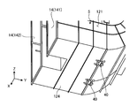
- FIG. 4 is an exploded perspective view schematically showing a part of the steam turbine system according to the first embodiment.
- FIG. 5 is a perspective view schematically showing an example of the outer compartment according to the first embodiment.
- FIG. 6 is an enlarged perspective view of a part of the outer casing according to the first embodiment.
- FIG. 7 is a diagram schematically illustrating the relationship between the first anchor member and the second anchor member according to the first embodiment.
- FIG. 8 is a cross-sectional view showing the vicinity of the upper surface of the support member according to the first embodiment.
- FIG. 9 is a diagram schematically illustrating a lateral displacement distribution of the outer casing according to the first embodiment.
- FIG. 10 is a diagram schematically illustrating a lateral displacement distribution of the outer casing according to the first embodiment.
- FIG. 11 is a cross-sectional view illustrating an example of a steam turbine system according to the second embodiment.
- FIG. 12 is a perspective view of the outer casing according to the second embodiment as viewed from the lower surface side.
- FIG. 13 is a perspective view showing the inside of the outer casing according to the second embodiment.
- FIG. 14 is a schematic diagram illustrating a relationship among the rib, the reinforcing plate, and the third anchor member according to the second embodiment.
- an XYZ orthogonal coordinate system is set, and the positional relationship of each part will be described with reference to this XYZ orthogonal coordinate system.
- the direction parallel to the X axis (first axis) in the horizontal plane is the X axis direction
- the direction parallel to the Y axis (second axis) orthogonal to the X axis in the horizontal plane is the Y axis direction
- the Z axis is orthogonal to the horizontal plane
- a direction parallel to the third axis) is taken as a Z-axis direction.
- the rotation or tilt directions around the X axis, the Y axis, and the Z axis are the ⁇ X, ⁇ Y, and ⁇ Z directions, respectively.
- the XY plane is parallel to the horizontal plane.
- FIG. 1 is a schematic configuration diagram illustrating an example of a steam turbine system 1 according to the present embodiment.
- a steam turbine system 1 includes a steam generator 2 that generates high-pressure steam, a high-pressure steam turbine 3 that is supplied with high-pressure steam from the steam generator 2, a steam generator 2, and a high-pressure A moisture separation heater 4 that separates and heats the moisture of the steam from the steam turbine 3, a low pressure steam turbine 5 that is supplied with low pressure steam from the moisture separation heater 4, a high pressure steam turbine 3, and a low pressure A generator 6 that generates electric power by the operation of the steam turbine 5, a high-pressure steam turbine 3, a low-pressure steam turbine 5, a turbine mount 7 that supports the generator 6, and a turbine rotor 8 are provided.
- the turbine mount 7 is fixed to a support surface FL such as a floor surface of a building, for example.
- the high pressure steam turbine 3 and the low pressure steam turbine 5 are connected via a turbine rotor 8.
- the generator 6 generates power by the rotational energy of the turbine rotor 8.
- FIG. 2 is a cross-sectional view showing an example of the low-pressure steam turbine 5 according to the present embodiment.
- the low-pressure steam turbine 5 includes a turbine rotor 8, an inner casing 11 that houses the turbine rotor 8, and an outer casing 12 that houses the inner casing 11.
- the turbine rotor 8 is rotatably supported by a rotor bearing disposed outside the outer casing 12.
- the turbine rotor 8 rotates around a rotation axis AX extending in the X-axis direction.
- the rotation axis AX and the X axis are parallel.
- the X-axis direction is appropriately referred to as an axial direction
- the Y-axis direction is appropriately referred to as a lateral direction
- the Z-axis direction is appropriately referred to as a vertical direction.
- the outer casing 12 has a steam inlet 13 into which steam from the moisture separator / heater 4 is introduced.
- the steam inlet 13 is provided in the upper part of the outer casing 12. Steam from the moisture separator / heater 4 is introduced into the outer casing 12 and the inner casing 11 through the steam inlet 13.
- the turbine rotor 8 has multistage blade rows 15 along the X-axis direction.
- the cascade 15 is disposed in the internal space of the inner casing 11. In the internal space of the inner casing 11, the steam is divided into one side and the other side in the X-axis direction.
- the low pressure steam turbine 5 is a double flow system (double flow system) steam turbine that diverts the steam that has flowed into the inner casing 11 to one side and the other side in the X-axis direction.
- An exhaust chamber 19 in which steam (exhaust gas) that has passed through the blade row 15 is discharged is provided in the inner space of the outer casing 12. During normal operation, the exhaust chamber 19 is maintained in a vacuum state. The steam that has worked in the low-pressure steam turbine 5 is exhausted from the outer casing 12 through the exhaust chamber 19.
- the outer casing 12 has an outer surface 121 that intersects the X axis.
- An opening 122 in which at least a part of the turbine rotor 8 is disposed is provided in the outer surface 121.
- the outer side surface 121 has a cone portion 123 disposed around the opening 122.
- the cone portion 123 has a conical surface that is recessed toward the inner space of the outer casing 12.
- the rotor bearing that rotatably supports the turbine rotor 8 is disposed in the vicinity of the cone portion 123.
- FIG. 3 is a side view showing a part of the steam turbine system 1 according to the present embodiment.
- illustration of the high pressure steam turbine 3 and the generator 6 is abbreviate
- the steam turbine system 1 includes a low-pressure steam turbine 5, an intermediate body 9, and a condenser 10.
- the outer casing 12 of the low-pressure steam turbine 5 has an exhaust port 14 for discharging steam that has worked in the low-pressure steam turbine 5.
- the exhaust port 14 is provided in the lateral direction of the outer casing 12. In the present embodiment, the exhaust port 14 is provided on the ⁇ Y side of the outer casing 12.
- the steam that has worked in the low-pressure steam turbine 5 is discharged laterally from the exhaust port 14 through the exhaust chamber 19 of the outer casing 12. That is, in this embodiment, the outer casing 12 discharges steam from the exhaust port 14 by a side exhaust system.
- the steam discharged from the exhaust port 14 is supplied to the capacitor 10 through the intermediate cylinder 9.
- the intermediate cylinder 9 is disposed between the low-pressure steam turbine 5 and the condenser 10.
- the intermediate body 9 is connected to each of the low-pressure steam turbine 5 and the condenser 10.
- the condenser 10 is connected to the low-pressure steam turbine 5 through the intermediate body 9.
- the intermediate cylinder 9 has an inlet 91 connected to the low-pressure steam turbine 5, an outlet 92 connected to the condenser 10, and a flow path 90 provided between the inlet 91 and the outlet 92.
- a telescopic member 16 is provided between the low pressure steam turbine 5 and the intermediate body 9.
- the steam discharged from the exhaust port 14 of the low-pressure steam turbine 5 passes through the flow path of the expansion and contraction member 16 and then flows into the flow path 90 of the intermediate cylinder 9 through the inflow port 91.
- the steam that has flowed through the flow path 90 is supplied to the condenser 10 via the outlet 92.
- the condenser 10 is disposed in the lateral direction of the outer casing 12 of the low-pressure steam turbine 5.
- the condenser 10 is disposed in the ⁇ Y direction of the low-pressure steam turbine 5. That is, in the present embodiment, the steam turbine system 1 is a side condenser type in which the condenser 10 is disposed in the lateral direction ( ⁇ Y direction) of the outer casing 12.
- the capacitor 10 may be disposed on each side of the outer casing 12 in the lateral direction (+ Y direction and ⁇ Y direction).
- the steam discharged from the exhaust port 14 of the low-pressure steam turbine 5 is supplied to the condenser 10 through the intermediate cylinder 9.
- the condenser 10 takes heat from the steam discharged from the low-pressure steam turbine 5 and liquefies the steam.
- the water generated in the condenser 10 is returned to the steam generator 2.
- the turbine mount 7 supports the outer casing 12 of the low-pressure steam turbine 5.
- the turbine mount 7 is made of concrete or reinforced concrete. Note that at least a part of the turbine mount 7 may be made of steel.
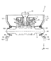
- FIG. 4 is an exploded perspective view schematically showing a part of the steam turbine system 1 according to the present embodiment.
- the high-pressure steam turbine 3 and the generator 6 are not shown.
- the outer casing 12 of the low-pressure steam turbine 5 has an outer surface 121 that intersects the X axis and a lower surface 124 that intersects the Z axis.
- the outer side surface 121 includes a first outer side surface 121 facing the + X direction and a second outer side surface 121 facing the ⁇ X direction.
- the exhaust port 14 of the outer casing 12 includes a first exhaust port 141 and a second exhaust port 142.
- the first exhaust port 141 and the second exhaust port 142 are disposed apart from each other in the X-axis direction.
- the inflow port 91 of the intermediate cylinder 9 includes a first inflow port 911 connected to the first exhaust port 141 and a second inflow port 912 connected to the second exhaust port 142.
- each of an installation position 3P of the high-pressure steam turbine 3, an installation position 5P of the low-pressure steam turbine 5, and an installation position 6P of the generator 6 is defined in the turbine mount 7.
- the turbine mount 7 has a support surface 72 that faces the lower surface 124 of the outer casing 12 and an opposing surface 73 that faces the outer surface 121 of the outer casing 12.
- the turbine mount 7 has a support member 70 that supports at least a part of the inner casing 11 via the outer casing 12.
- the support member 70 protrudes upward from the support surface 72.
- the support member 70 is disposed between the outer casing 12 and the intermediate body 9.
- the support member 70 is disposed so as to support the central portions of the inner casing 11 and the outer casing 12 in the X-axis direction.
- the support member 70 has an upper surface 71 facing the + Z direction.
- the support member 70 supports the inner casing 11 on the upper surface 71.
- the upper surface 71 of the support member 70 that supports the inner casing 11 is disposed above the support surface 72.
- the steam turbine system 1 is fixed to at least a part of the first anchor member 40 fixed to at least a part of the surface of the outer casing 12 and the turbine mount 7.
- a second anchor member 50 that contacts the first anchor member 40 and suppresses lateral displacement of the outer casing 12 is provided.
- the first anchor member 40 protrudes from the surface of the outer casing 12.
- the first anchor member 40 is fixed to at least a part of the surface of the outer casing 12.
- the surface of the outer casing 12 to which the first anchor member 40 is fixed includes the outer side surface 121 of the outer casing 12. That is, in the present embodiment, the first anchor member 40 is fixed to the outer side surface 121 that intersects the X axis among the surface of the outer casing 12.
- the outer surface 121 includes a first outer surface 121 facing the + X direction and a second outer surface 121 facing the ⁇ X direction.
- the first anchor member 40 is fixed to each of the first outer surface 121 and the second outer surface 121.
- the turbine mount 7 has a facing surface 73 that faces the outer surface 121.
- the second anchor member 50 protrudes from the facing surface 73 of the turbine mount 7 and is fixed to the facing surface 73 of the turbine mount 7.
- the second anchor member 50 includes a second anchor member 501 disposed on the + Y side of the first anchor member 40 and a second anchor member 502 disposed on the ⁇ Y side of the first anchor member 40.
- the second anchor member 50 comes into contact with the first anchor member 40 and suppresses the lateral displacement of the outer casing 12.
- the displacement of the outer casing 12 in the + Y direction is suppressed.
- the displacement of the outer casing 12 in the ⁇ Y direction is suppressed.
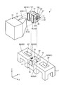
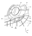
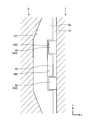
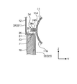
- FIG. 5 is a perspective view schematically showing an example of the outer compartment 12 according to the present embodiment.
- FIG. 6 is an enlarged perspective view of a part of the outer casing 12 according to the present embodiment.
- FIG. 7 is a view schematically showing the relationship between the first anchor member 40 and the second anchor member 50 according to the present embodiment.
- the first anchor member 40 is fixed to the cone portion 123 of the outer side surface 121 of the outer casing 12.
- the support member 60 is fixed to the cone portion 123.
- the first anchor member 40 is fixed to the support member 60.
- the first anchor member 40 is fixed to the cone portion 123 via the support member 60.
- the first anchor member 40 In the horizontal direction (Y-axis direction), at least a part of the first anchor member 40 is disposed at the same position as the rotation axis AX. That is, the Y coordinate of the rotation axis AX and the Y coordinate of at least a part of the first anchor member 40 are the same. In the present embodiment, the center of the first anchor member 40 and the rotation axis AX are disposed at the same position in the lateral direction.
- the first anchor member 40 is a rectangular parallelepiped member.
- the dimension of the first anchor member 40 in the X-axis direction is smaller than the dimension of the first anchor member 40 in the Y-axis direction.
- the dimension of the first anchor member 40 in the Z-axis direction is larger than the dimension of the first anchor member 40 in the X-axis direction. That is, in the present embodiment, the first anchor member 40 is a thin plate member.
- the support member 60 is a plate-like member that is long in the lateral direction (Y-axis direction).
- the support member 60 has an end surface 601 that is fixed to the surface of the cone portion 123 and a support surface 602 to which the first anchor member 40 is fixed.
- the first anchor member 40 is fixed to a support surface 602 that is one end portion of the support member 60 in the axial direction (X-axis direction) (the end portion on the + X side in FIG. 6).
- the first anchor member 40 is fixed to the cone portion 123 via the support member 60 so as to be separated from the outer side surface 121 of the outer casing 12.
- the support member 60 has a recess 603 at one end in the axial direction.
- the support surface 602 is the inner surface of the recess 603.
- the first anchor member 40 is fixed to a support surface 602 that is the inner surface of the recess 603.
- the upper end portion of the first anchor member 40 and the support member 60 are fixed.
- the center part of the 1st anchor member 40 and the support member 60 may be fixed, and the lower end part of the 1st anchor member 40 and the support member 60 may be fixed.
- the number of support members 60 is one, but a plurality of support members 60 may be fixed to the cone portion 123 and the first anchor member 40 may be fixed to the plurality of support members 60.
- the second anchor member 50 (501, 502) is disposed in the lateral direction of the first anchor member 40.
- the first anchor member 40 is disposed between one second anchor member 501 and the other second anchor member 502.
- the outer compartment 12 is divided into two parts in the vertical direction, and has an upper half part 12A and a lower half part 12B. Steam is introduced into the inner compartment 11 from the steam inlet 13 of the upper half 12A. The upper half 12A and the lower half 12B are joined together.
- the outer vehicle compartment 12 has an exhaust port 14 provided on the -Y side and an exhaust passage 30 connected to the exhaust port 14.
- the exhaust passage 30 extends in the Y-axis direction.
- the exhaust port 14 is disposed at the end of the exhaust passage 30 on the ⁇ Y side.
- the steam in the exhaust chamber 19 is exhausted from the exhaust port 14 after flowing through the exhaust passage 30.
- the exhaust port 14 includes a first exhaust port 141 and a second exhaust port 142.
- the first exhaust port 141 and the second exhaust port 142 are arranged apart from each other in the X-axis direction.
- the first exhaust port 141 is disposed on the ⁇ X side with respect to the second exhaust port 142.
- the exhaust passage 30 includes a first exhaust passage 301 connected to the first exhaust port 141 and a second exhaust passage 302 connected to the second exhaust port 142.
- the first exhaust passage 301 and the second exhaust passage 302 are arranged apart from each other in the X-axis direction.
- the first exhaust passage 301 is disposed on the ⁇ X side with respect to the second exhaust passage 302.
- the turbine mount 7 has a support member 70 that supports at least a part of the inner casing 11 through the outer casing 12 outside the exhaust passage 30.
- the support member 70 is disposed between the outer casing 12 and the intermediate body 9.
- the support member 70 is disposed so as to support the central portions of the inner casing 11 and the outer casing 12 in the X-axis direction.
- FIG. 8 is a cross-sectional view showing the vicinity of the upper surface 71 of the support member 70 according to the present embodiment.
- the outer casing 12 has a lower surface 23 that can face the upper surface 71 of the support member 70.
- the lower surface 23 faces the ⁇ Z direction.
- the support member 70 supports the outer casing 12 by bringing the upper surface 71 and the lower surface 23 into contact with each other.
- the end surface 32 of the outer casing 12 includes a first end surface 321 and a second end surface 322 disposed on the ⁇ Z side with respect to the first end surface 321 and disposed on the + X side with respect to the first end surface 321.
- a step portion is provided between the first end surface 321 and the second end surface 322.
- the lower surface 23 is disposed between the first end surface 321 and the second end surface 322.
- the support member 70 faces the second end surface 322 in a state where the upper surface 71 and the lower surface 23 are in contact with each other.
- the inner compartment 11 has a flange portion 24.
- the inner compartment 11 is divided into two parts in the vertical direction, and has an upper half part 11A and a lower half part 11B.
- the flange portion 24A is formed by joining the flange portion 24A of the upper half portion 11A and the flange portion 24B of the lower half portion 11B.
- the outer casing 12 has an upper surface 26 facing in the direction opposite to the lower surface 23.
- the upper surface 26 and the lower surface 23 are provided on the plate portion 27 of the outer casing 12.
- a plate member 25 is disposed between the upper surface 26 and the flange portion 24.
- the support member 70 supports the inner casing 11 (the flange portion 24) via the plate portion 27 of the outer casing 12 and the plate member 25 disposed inside the outer casing 12.
- the plate member 25 may be omitted.
- the low-pressure steam turbine 5 is a double flow system, and the steam introduced into the inner casing 11 flows into the central portion of the inner casing 11 in the X-axis direction.
- the steam that has flowed into the inner casing 11 flows to one side and the other side in the X-axis direction.
- the steam that has worked in the low-pressure steam turbine 5 flows through the exhaust chamber 19 and then through the first exhaust passage 301 and the second exhaust passage 302.
- the steam that flows from the center of the inner casing 11 to the ⁇ X side flows exclusively through the first exhaust passage 301 and flows from the center of the inner casing 11 to the + X side.
- the steam that has flowed through the first exhaust passage 301 is discharged from the first exhaust port 141 and flows into the flow path 90 through the first inflow port 911 of the intermediate cylinder 9.
- the steam flowing through the second exhaust passage 302 is discharged from the second exhaust port 142 and flows into the flow path 90 through the second inlet 912 of the intermediate cylinder 9.
- the steam in the flow path 90 flows out of the intermediate cylinder 9 and is then supplied to the capacitor 10.
- a side capacitor system in which the capacitor 10 is arranged in the lateral direction of the outer casing 12 is employed. Since the exhaust port 14 is provided in the side part of the outer casing 12 and the exhaust port 14 and the condenser 10 are connected via the intermediate body 9, the steam discharged from the low-pressure steam turbine 5 is smoothly supplied to the condenser 10. To be supplied.
- the exhaust chamber 19 which is the internal space of the outer casing 12 is maintained in a vacuum state.
- the external space of the outer compartment 12 is in an atmospheric pressure state.
- the outer casing 12 approaches the capacitor 10 in the lateral direction ( ⁇ ) due to the pressure difference between the inner space of the outer casing 12 and the outer space. There is a possibility of displacement in the Y direction).
- the first anchor member 40 is fixed to at least a part of the surface of the outer casing 12, and the second anchor member 50 is fixed to at least a part of the turbine mount 7.
- the first anchor member 40 and the second anchor member 50 are arranged in the lateral direction (Y-axis direction). Moreover, the 1st anchor member 40 and the 2nd anchor member 50 are arrange
- the turbine mount 7 is fixed to the support surface FL. Therefore, even if the outer casing 12 is about to be displaced in the lateral direction, the lateral displacement of the outer casing 12 is suppressed by the first anchor member 40 and the second anchor member 50 coming into contact with each other.
- the first anchor member 40 is provided in the outer casing 12, and the second anchor member 50 is provided in the turbine mount 7. Therefore, in the side condenser system, even if the outer casing 12 is displaced laterally so as to be attracted to the capacitor 10 due to the pressure difference between the inner space and the outer space of the outer casing 12, the displacement of the outer casing 12 is increased. Is suppressed by the first anchor member 40 and the second anchor member 50. Thereby, the fluctuation
- the first anchor member 40 is disposed at the same position as the rotation axis AX in the lateral direction. Therefore, the relative position between the turbine rotor 8 and the first anchor member 40 can be grasped smoothly. Therefore, for example, the assembly work of arranging the first anchor member 40 between the pair of second anchor members 50 is smoothly performed.
- the first anchor member 40 is fixed to the outer side surface 121 of the outer casing 12. Thereby, the positioning operation
- the first anchor member 40 is fixed to the cone portion 123 of the outer casing 12.
- the first anchor member 40 is preferably provided in the upper part of the outer casing 12 as much as possible.
- the outer surface 121 of the lower half 12B of the outer casing 12 faces the facing surface 73 of the turbine mount 7, and the upper half 12A of the outer casing 12 does not face the turbine mount 7.
- the first anchor member 40 is fixed to the uppermost cone portion 123 of the outer surface 121 of the lower half portion 12B, so that the lateral displacement of the outer casing 12 is effectively suppressed.
- the support member 60 is fixed to the cone portion 123, and the first anchor member 40 is fixed to the end portion of the support member 60 in the axial direction. Accordingly, the first anchor member 40 can be separated from the cone portion 123 in the cone portion 123 that is recessed toward the inner space side of the outer casing 12. Therefore, the assembling work for arranging the first anchor member 40 between the pair of second anchor members 50 is smoothly performed.
- the support member 60 has a plate shape that is long in the lateral direction. Thereby, the lateral displacement and deformation of the outer casing 12 are effectively suppressed by the support member 60.
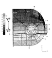
- FIGS. 9 and 10 are diagrams schematically showing a displacement distribution in the lateral direction of the outer casing 12 according to the present embodiment.
- 9 and 10 nine regions (region A to region I) having different amounts of displacement in the horizontal direction are shown.
- the first region A shows a portion of the outer casing 12 that is displaced in a direction away from the capacitor 10 (+ Y direction).
- the second region B shows a portion of the outer casing 12 that has the smallest displacement.
- the third region C to the ninth region I indicate a portion of the outer casing 12 that is displaced in a direction approaching the capacitor 10 ( ⁇ Y direction).
- the displacement of the portion of the ninth region I is the largest, and the displacement of the portion of the third region C is the smallest.
- FIG. 9 shows a lateral displacement distribution of the outer casing 12 in which the first anchor member 40 is provided but the support member 60 is not provided.
- FIG. 10 shows a lateral displacement distribution of the outer casing 12 in which the support member 60 is provided and the first anchor member 40 is fixed via the support member 60.
- FIG. 9 it is visually recognized that the displacement of the outer casing 12 in the ⁇ Y direction is suppressed by providing the first anchor member 40.
- FIG. 10 it is visually recognized that the support member 60 is provided in addition to the first anchor member 40 to further effectively suppress the displacement of the outer casing 12 in the ⁇ Y direction.
- the support member 60 has a recess 603 at the end in the axial direction, and the first anchor member 40 is fixed to the support surface 602 that is the inner surface of the recess 603. Thereby, the positioning operation of the first anchor member 40 and the second anchor member 50 is smoothly performed by inserting the second anchor member 50 into the recess 603.
- the dimension of the first anchor member 40 in the axial direction is smaller than the dimension of the first anchor member 40 in the lateral direction (Y-axis direction). Therefore, the dimension of the low-pressure steam turbine 5 is suppressed from increasing in the axial direction.
- FIG. 11 is a cross-sectional view showing an example of the steam turbine system 1 according to the present embodiment.
- the first anchor member 40 is fixed to the lower surface 124 of the outer casing 12.
- the first anchor member 40 protrudes downward from the lower surface 124 of the outer casing 12.
- the second anchor member 50 is provided on the support surface 72 of the turbine mount 7.
- the second anchor member 50 may be omitted, and the first anchor member 40 may be fitted into a recess formed in the support surface 72 of the turbine mount 7.
- the outer casing 12 has a bottom surface 125 that faces the lower surface of the inner casing 11.
- the third anchor member 55 is fixed to at least a part of the bottom surface 125 of the outer casing 12.
- the third anchor member 55 protrudes upward from the bottom surface 125 of the outer casing 12.
- the fourth anchor member 58 is fixed to at least a part of the lower surface of the inner casing 11.
- the fourth anchor member 58 is in contact with the third anchor member 55 and suppresses the lateral displacement of the inner casing 11. Note that the fourth anchor member 58 may be omitted, and the third anchor member 55 may be fitted into a recess formed in the lower surface of the inner casing 11.
- the first anchor member 40 and the third anchor member 55 are disposed at the same position in the axial direction (X-axis direction) and the lateral direction (Y-axis direction).
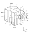
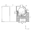
- FIG. 12 is a perspective view of the outer casing 12 according to the present embodiment as viewed from the lower surface 124 side.
- FIG. 13 is a perspective view showing the inside of the outer casing 12 according to the present embodiment.
- the first anchor member 40 is provided on the lower surface 124 of the outer casing 12.
- a plurality of first anchor members 40 are provided in the axial direction.
- two first anchor members 40 are provided in the axial direction.
- the first anchor member 40 may be provided in any number of three or more in the axial direction.
- the rib 17 is fixed to the bottom surface 125 of the outer casing 12. Further, the reinforcing plate 18 is fixed to the bottom surface 125.
- the third anchor member 55 is fixed to each of the rib 17 and the reinforcing plate 18.
- FIG. 14 is a schematic diagram showing the relationship among the rib 17, the reinforcing plate 18, and the third anchor member 55 according to the present embodiment. As shown in FIG. 14, the rib 17 and the reinforcing plate 18 are fixed to the bottom surface 125. The reinforcing plate 18 faces the rib 17 with a gap. The third anchor member 55 is fixed to each of the rib 17 and the reinforcing plate 18.
- the first anchor member 40 is fixed to the lower surface 124 of the outer casing 12. Also in this embodiment, the lateral displacement of the outer casing 12 is suppressed. Further, by providing a plurality of first anchor members 40 in the axial direction, not only the lateral displacement (Y-axis direction) of the outer casing 12 but also the displacement (rotation) in the ⁇ Z direction is suppressed.
- the third anchor member 55 is provided on the bottom surface 125 of the outer casing 12. Thereby, the displacement of the inner casing 11 in the lateral direction is suppressed, and the deterioration of the performance of the low-pressure steam turbine 5 is suppressed.
- the rib 17 is provided on the bottom surface 125, so that the rigidity of the outer casing 12 is ensured.
- the rib 17 and the reinforcing plate 18 are provided on the bottom surface 125, and the third anchor member 55 is fixed to each of the rib 17 and the reinforcing plate 18, so that sufficient rigidity of the outer casing 12 is ensured.
- the first anchor member 40 and the third anchor member 55 are arranged at the same position in the axial direction and the lateral direction. Therefore, the displacement of the outer casing 12 and the inner casing 11 is effectively suppressed.
Landscapes
- Engineering & Computer Science (AREA)
- Mechanical Engineering (AREA)
- General Engineering & Computer Science (AREA)
- Turbine Rotor Nozzle Sealing (AREA)
- Engine Equipment That Uses Special Cycles (AREA)
Applications Claiming Priority (2)
| Application Number | Priority Date | Filing Date | Title |
|---|---|---|---|
| JP2016204650A JP6701052B2 (ja) | 2016-10-18 | 2016-10-18 | 蒸気タービンシステム |
| JP2016-204650 | 2016-10-18 |
Publications (1)
| Publication Number | Publication Date |
|---|---|
| WO2018073996A1 true WO2018073996A1 (ja) | 2018-04-26 |
Family
ID=62018360
Family Applications (1)
| Application Number | Title | Priority Date | Filing Date |
|---|---|---|---|
| PCT/JP2017/016325 Ceased WO2018073996A1 (ja) | 2016-10-18 | 2017-04-25 | 蒸気タービンシステム |
Country Status (2)
| Country | Link |
|---|---|
| JP (1) | JP6701052B2 (enExample) |
| WO (1) | WO2018073996A1 (enExample) |
Families Citing this family (2)
| Publication number | Priority date | Publication date | Assignee | Title |
|---|---|---|---|---|
| JP6833745B2 (ja) * | 2018-03-06 | 2021-02-24 | 株式会社東芝 | 蒸気タービン |
| JP7199248B2 (ja) | 2019-02-22 | 2023-01-05 | 三菱重工業株式会社 | 車室、及び蒸気タービン |
Citations (5)
| Publication number | Priority date | Publication date | Assignee | Title |
|---|---|---|---|---|
| JP2001082108A (ja) * | 1999-09-09 | 2001-03-27 | Mitsubishi Heavy Ind Ltd | 復水器一体型低圧タービン |
| JP2011043103A (ja) * | 2009-08-21 | 2011-03-03 | Mitsubishi Heavy Ind Ltd | 蒸気タービン車室、これを備えた蒸気タービンおよびこれを備えた原子力発電プラントならびに蒸気タービン車室の組立方法 |
| JP2012112254A (ja) * | 2010-11-19 | 2012-06-14 | Mitsubishi Heavy Ind Ltd | 低圧蒸気タービンの車室構造 |
| JP2013104297A (ja) * | 2011-11-10 | 2013-05-30 | Mitsubishi Heavy Ind Ltd | 蒸気タービン低圧車室 |
| JP2014163368A (ja) * | 2013-02-28 | 2014-09-08 | Hitachi Ltd | 軸流蒸気タービン、および軸流蒸気タービンの改造方法 |
Family Cites Families (3)
| Publication number | Priority date | Publication date | Assignee | Title |
|---|---|---|---|---|
| JPS59133701U (ja) * | 1983-02-28 | 1984-09-07 | 三菱重工業株式会社 | タ−ビン車室据付調整装置 |
| JP5374454B2 (ja) * | 2010-07-16 | 2013-12-25 | 三菱重工業株式会社 | 軸受箱固定方法及び装置 |
| JP6087803B2 (ja) * | 2013-12-25 | 2017-03-01 | 三菱重工業株式会社 | 蒸気タービン |
-
2016
- 2016-10-18 JP JP2016204650A patent/JP6701052B2/ja active Active
-
2017
- 2017-04-25 WO PCT/JP2017/016325 patent/WO2018073996A1/ja not_active Ceased
Patent Citations (5)
| Publication number | Priority date | Publication date | Assignee | Title |
|---|---|---|---|---|
| JP2001082108A (ja) * | 1999-09-09 | 2001-03-27 | Mitsubishi Heavy Ind Ltd | 復水器一体型低圧タービン |
| JP2011043103A (ja) * | 2009-08-21 | 2011-03-03 | Mitsubishi Heavy Ind Ltd | 蒸気タービン車室、これを備えた蒸気タービンおよびこれを備えた原子力発電プラントならびに蒸気タービン車室の組立方法 |
| JP2012112254A (ja) * | 2010-11-19 | 2012-06-14 | Mitsubishi Heavy Ind Ltd | 低圧蒸気タービンの車室構造 |
| JP2013104297A (ja) * | 2011-11-10 | 2013-05-30 | Mitsubishi Heavy Ind Ltd | 蒸気タービン低圧車室 |
| JP2014163368A (ja) * | 2013-02-28 | 2014-09-08 | Hitachi Ltd | 軸流蒸気タービン、および軸流蒸気タービンの改造方法 |
Also Published As
| Publication number | Publication date |
|---|---|
| JP2018066303A (ja) | 2018-04-26 |
| JP6701052B2 (ja) | 2020-05-27 |
Similar Documents
| Publication | Publication Date | Title |
|---|---|---|
| JP5180652B2 (ja) | 蒸気タービンの車室構造 | |
| US9388701B2 (en) | Turbine | |
| KR100628907B1 (ko) | 조립식 노즐 다이어프램 | |
| JP7213141B2 (ja) | 両吸込渦巻ポンプ | |
| KR20210031507A (ko) | 증기 터빈의 배기실, 증기 터빈 및 증기 터빈의 교환 장착 방법 | |
| WO2018073996A1 (ja) | 蒸気タービンシステム | |
| JP6087803B2 (ja) | 蒸気タービン | |
| CN106640741B (zh) | 密封件及压缩机及空调器 | |
| US10851706B2 (en) | Variable nozzle mechanism and variable displacement type exhaust turbocharger | |
| CN113840984B (zh) | 真空泵及真空泵构成零件 | |
| CN103174667A (zh) | 蜂窝密封件和方法 | |
| CN101096919A (zh) | 涡轮机 | |
| JP6049582B2 (ja) | 蒸気タービン | |
| US10662817B2 (en) | Steam turbine | |
| EP2829736B1 (en) | Electric air blower | |
| US20180142574A1 (en) | Steam turbine | |
| JP7001161B2 (ja) | 過給機 | |
| JP6833745B2 (ja) | 蒸気タービン | |
| US20080304985A1 (en) | Turbo-molecular pump | |
| JP2020125695A (ja) | ターボ式流体機械 | |
| US8142151B2 (en) | Intermediate housing floor for a fluid kinetic machine | |
| US9790813B2 (en) | Twist prevention for turbomachinery | |
| JP5966417B2 (ja) | 過給機 | |
| JP2015081607A (ja) | ターボ機械 | |
| JP2016089650A (ja) | ロータリ圧縮機 |
Legal Events
| Date | Code | Title | Description |
|---|---|---|---|
| 121 | Ep: the epo has been informed by wipo that ep was designated in this application |
Ref document number: 17861309 Country of ref document: EP Kind code of ref document: A1 |
|
| NENP | Non-entry into the national phase |
Ref country code: DE |
|
| 122 | Ep: pct application non-entry in european phase |
Ref document number: 17861309 Country of ref document: EP Kind code of ref document: A1 |