WO2018070339A1 - リニアモータ制御装置及びこれを搭載した圧縮機 - Google Patents
リニアモータ制御装置及びこれを搭載した圧縮機 Download PDFInfo
- Publication number
- WO2018070339A1 WO2018070339A1 PCT/JP2017/036319 JP2017036319W WO2018070339A1 WO 2018070339 A1 WO2018070339 A1 WO 2018070339A1 JP 2017036319 W JP2017036319 W JP 2017036319W WO 2018070339 A1 WO2018070339 A1 WO 2018070339A1
- Authority
- WO
- WIPO (PCT)
- Prior art keywords
- mover
- voltage
- linear motor
- frequency
- load
- Prior art date
- Legal status (The legal status is an assumption and is not a legal conclusion. Google has not performed a legal analysis and makes no representation as to the accuracy of the status listed.)
- Ceased
Links
Images








Classifications
-
- H—ELECTRICITY
- H02—GENERATION; CONVERSION OR DISTRIBUTION OF ELECTRIC POWER
- H02P—CONTROL OR REGULATION OF ELECTRIC MOTORS, ELECTRIC GENERATORS OR DYNAMO-ELECTRIC CONVERTERS; CONTROLLING TRANSFORMERS, REACTORS OR CHOKE COILS
- H02P6/00—Arrangements for controlling synchronous motors or other dynamo-electric motors using electronic commutation dependent on the rotor position; Electronic commutators therefor
- H02P6/20—Arrangements for starting
-
- F—MECHANICAL ENGINEERING; LIGHTING; HEATING; WEAPONS; BLASTING
- F04—POSITIVE - DISPLACEMENT MACHINES FOR LIQUIDS; PUMPS FOR LIQUIDS OR ELASTIC FLUIDS
- F04B—POSITIVE-DISPLACEMENT MACHINES FOR LIQUIDS; PUMPS
- F04B35/00—Piston pumps specially adapted for elastic fluids and characterised by the driving means to their working members, or by combination with, or adaptation to, specific driving engines or motors, not otherwise provided for
- F04B35/04—Piston pumps specially adapted for elastic fluids and characterised by the driving means to their working members, or by combination with, or adaptation to, specific driving engines or motors, not otherwise provided for the means being electric
-
- H—ELECTRICITY
- H02—GENERATION; CONVERSION OR DISTRIBUTION OF ELECTRIC POWER
- H02K—DYNAMO-ELECTRIC MACHINES
- H02K41/00—Propulsion systems in which a rigid body is moved along a path due to dynamo-electric interaction between the body and a magnetic field travelling along the path
- H02K41/02—Linear motors; Sectional motors
- H02K41/03—Synchronous motors; Motors moving step by step; Reluctance motors
- H02K41/031—Synchronous motors; Motors moving step by step; Reluctance motors of the permanent magnet type
- H02K41/033—Synchronous motors; Motors moving step by step; Reluctance motors of the permanent magnet type with armature and magnets on one member, the other member being a flux distributor
-
- H—ELECTRICITY
- H02—GENERATION; CONVERSION OR DISTRIBUTION OF ELECTRIC POWER
- H02P—CONTROL OR REGULATION OF ELECTRIC MOTORS, ELECTRIC GENERATORS OR DYNAMO-ELECTRIC CONVERTERS; CONTROLLING TRANSFORMERS, REACTORS OR CHOKE COILS
- H02P25/00—Arrangements or methods for the control of AC motors characterised by the kind of AC motor or by structural details
- H02P25/02—Arrangements or methods for the control of AC motors characterised by the kind of AC motor or by structural details characterised by the kind of motor
- H02P25/032—Reciprocating, oscillating or vibrating motors
-
- H—ELECTRICITY
- H02—GENERATION; CONVERSION OR DISTRIBUTION OF ELECTRIC POWER
- H02P—CONTROL OR REGULATION OF ELECTRIC MOTORS, ELECTRIC GENERATORS OR DYNAMO-ELECTRIC CONVERTERS; CONTROLLING TRANSFORMERS, REACTORS OR CHOKE COILS
- H02P25/00—Arrangements or methods for the control of AC motors characterised by the kind of AC motor or by structural details
- H02P25/02—Arrangements or methods for the control of AC motors characterised by the kind of AC motor or by structural details characterised by the kind of motor
- H02P25/06—Linear motors
- H02P25/064—Linear motors of the synchronous type
- H02P25/066—Linear motors of the synchronous type of the stepping type
-
- F—MECHANICAL ENGINEERING; LIGHTING; HEATING; WEAPONS; BLASTING
- F04—POSITIVE - DISPLACEMENT MACHINES FOR LIQUIDS; PUMPS FOR LIQUIDS OR ELASTIC FLUIDS
- F04B—POSITIVE-DISPLACEMENT MACHINES FOR LIQUIDS; PUMPS
- F04B2203/00—Motor parameters
- F04B2203/04—Motor parameters of linear electric motors
- F04B2203/0401—Current
-
- F—MECHANICAL ENGINEERING; LIGHTING; HEATING; WEAPONS; BLASTING
- F04—POSITIVE - DISPLACEMENT MACHINES FOR LIQUIDS; PUMPS FOR LIQUIDS OR ELASTIC FLUIDS
- F04B—POSITIVE-DISPLACEMENT MACHINES FOR LIQUIDS; PUMPS
- F04B2203/00—Motor parameters
- F04B2203/04—Motor parameters of linear electric motors
- F04B2203/0402—Voltage
-
- F—MECHANICAL ENGINEERING; LIGHTING; HEATING; WEAPONS; BLASTING
- F04—POSITIVE - DISPLACEMENT MACHINES FOR LIQUIDS; PUMPS FOR LIQUIDS OR ELASTIC FLUIDS
- F04B—POSITIVE-DISPLACEMENT MACHINES FOR LIQUIDS; PUMPS
- F04B2203/00—Motor parameters
- F04B2203/04—Motor parameters of linear electric motors
- F04B2203/0404—Frequency of the electric current
-
- F—MECHANICAL ENGINEERING; LIGHTING; HEATING; WEAPONS; BLASTING
- F25—REFRIGERATION OR COOLING; COMBINED HEATING AND REFRIGERATION SYSTEMS; HEAT PUMP SYSTEMS; MANUFACTURE OR STORAGE OF ICE; LIQUEFACTION SOLIDIFICATION OF GASES
- F25B—REFRIGERATION MACHINES, PLANTS OR SYSTEMS; COMBINED HEATING AND REFRIGERATION SYSTEMS; HEAT PUMP SYSTEMS
- F25B2400/00—Component parts or details not otherwise provided for in this subclass
- F25B2400/07—Details of compressors or related parts
- F25B2400/073—Linear compressors
Definitions
- the present invention relates to a linear motor control device and a compressor equipped with the same.
- Patent Document 1 discloses a configuration in which a phase of an induced voltage from a search coil is detected, a phase difference with a current phase flowing through a linear motor is detected, and the resonance frequency of the piston is matched according to the phase difference. Yes. Patent Document 1 describes a configuration in which the piston stroke is kept constant by correcting the voltage value of the output voltage by a value corresponding to the frequency of the output voltage.
- a search coil is provided in the winding of the linear compressor to detect the phase of the induced voltage.
- the search coil is used, not only the wiring becomes complicated, but also it is easily affected by noise, so it is not easy to control the resonance frequency with high accuracy.
- no consideration is given to the control suitable for ensuring the mover amplitude at an early stage and starting the linear motor, such as during startup.
- the present invention provides a linear motor control device capable of improving the estimation accuracy of the resonance frequency immediately after startup, and a compressor equipped with the linear motor control device.
- a linear motor control device of the present invention is a linear motor control device including a winding to which an AC voltage is applied and a mover to which an elastic body is connected, and the frequency of the AC voltage.
- the operation mode (1) for monotonously increasing the amplitude of the AC voltage while maintaining the constant voltage
- the operation mode (2) for changing the frequency of the AC voltage while maintaining the amplitude of the AC voltage substantially constant. And the operation mode (1) and the operation mode (2) are executed in this order.
- the compressor of the present invention is a compressor having a linear motor control device including a winding to which an alternating voltage is applied and a mover to which an elastic body is connected, and the linear motor control device includes: An operation mode (1) for monotonously increasing the amplitude of the AC voltage while keeping the frequency of the AC voltage substantially constant, and an operation mode (2) for changing the frequency of the AC voltage while keeping the amplitude of the AC voltage substantially constant. ) And executing in the order of the operation mode (1) and the operation mode (2), and estimating the position of the mover using the voltage and current values of the windings.
- FIG. 1 is an overall schematic configuration diagram of a linear motor system according to a first embodiment of the present invention. It is a perspective view of the structural example of an armature. It is a schematic diagram which shows the longitudinal cross-section of a magnetic pole, and the flow of magnetic flux. It is explanatory drawing of the polarity which generate
- FIG. 4 is an explanatory diagram illustrating a configuration example of a voltage command value generator 103.
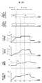
- FIG. It is explanatory drawing of a starting sequence. It is a figure explaining the time change of the main command value in each mode.
- It is explanatory drawing of the structural example of a phase difference detector, and the relationship between a drive frequency and a phase difference detector output.
- 5 is an explanatory diagram illustrating a configuration example of a drive frequency adjuster 131.
- FIG. It is explanatory drawing which shows the structural example of the stroke instruction
- FIG. It is explanatory drawing which shows the structural example of the stroke detector 152.
- FIG. FIG. 6 is an explanatory diagram showing a configuration example of a stroke controller 153.
- FIG. 6 is an explanatory diagram illustrating a configuration example of a phase difference detector according to a second embodiment. It is explanatory drawing of the relationship between the drive frequency of Example 2, and a phase difference detector output. It is explanatory drawing which shows the structural example of a position estimation part. It is a longitudinal cross-sectional view of the hermetic compressor of Example 3 which concerns on the other Example of this invention. It is a whole schematic block diagram of the linear motor system of Example 3.
- FIG. 10 is an explanatory diagram of a startup sequence according to the third embodiment. It is explanatory drawing which shows the structural example of the stroke controller 353 of Example 3.
- FIG. 10 is an explanatory diagram of a startup sequence according to the third embodiment. It is explanatory drawing which shows the structural example of the stroke controller 353 of Example 3.
- a plurality of components are formed as a single member, and a single component is formed of a plurality of members. It is allowed that a certain component is a part of another component, a part of a certain component overlaps a part of another component, and the like.
- front-rear direction, left-right direction, and up-down direction that are orthogonal to each other are used, but the gravitational direction is not necessarily parallel to the lower direction, and the front-rear direction, left-right direction, up-down direction, or It can be parallel to other directions.
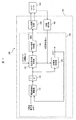
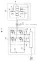
- FIG. 1 is an overall schematic configuration diagram of a linear motor system 100 according to a first embodiment of the present invention.
- the linear motor system 100 includes a linear motor driving device 101 and a linear motor 104.
- the linear motor 104 has an armature 9 and a mover 6 that move relative to each other.
- the linear motor drive device 101 includes a position detection unit 106, a control unit 102, and a power conversion circuit 105.
- the position detector 106 detects the relative position (mover position) of the mover 6 with respect to the armature 9.
- the mover 6 moves in the vertical direction, but the armature 9 and the mover 6 (field element) may move relative to each other, and the armature 9 may move in the vertical direction.
- the movable element 6 reciprocates in the vertical direction will be described as an example, but the direction of reciprocation is not limited to the vertical direction.
- the movable element 6 may be configured to reciprocate in the horizontal direction, or the movable element 6 may be configured to reciprocate in a direction having an arbitrary angle with respect to the vertical direction.
- the control unit 102 outputs an output voltage command value to the power conversion circuit 105 or a drive signal (pulse signal) for driving the power conversion circuit 105 according to the detection result of the position detection unit 106.
- the power conversion circuit 105 is an example of a power conversion unit that converts the voltage of the DC voltage source 120 and outputs an AC voltage. Note that a DC current source may be used instead of the DC voltage source 120.
- FIG. 2 is a perspective view of the linear motor 104 (a perspective view of a configuration example of the armature).
- the linear motor 104 of the present embodiment has a mover 6 that can move relative to the armature 9 in the direction (front-rear direction) in which the permanent magnets 2 (2a, 2b) are arranged.
- the armature 9 has two magnetic poles 7 that face each other in the vertical direction through a gap, and a winding 8 wound around the magnetic pole 7.
- the mover 6 is disposed in this gap.
- the magnetic pole 7 has magnetic pole teeth 70 as an end face facing the mover 6.
- the armature 9 can apply a force in the front-rear direction (hereinafter referred to as thrust) to the mover 6.
- the thrust can be controlled so that the mover 6 reciprocates in the front-rear direction.
- the mover 6 includes two flat permanent magnets 2 (2a, 2b) magnetized in the vertical direction.
- the rear permanent magnet 2a and the front permanent magnet 2b are magnetized in opposite directions.
- the rear permanent magnet 2a has an N pole on the upper side
- the front permanent magnet 2b has an S pole on the upper side.
- the permanent magnets 2a and 2b are shown, but the mover 6 is not shown.
- a flat plate with a flat permanent magnet 2 fixed can be adopted.
- the control unit 102 outputs a drive signal so that the mover 6 reciprocates in a range where the permanent magnets 2 a and 2 b face the armature 9.
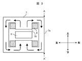
- FIG. 3 is a cross-sectional view taken along a line A-A ′ in FIG. 2 (A-A ′ cross-sectional view).
- the arrow lines in FIG. 3 show an example of magnetic flux lines when current is passed through the two windings 8.
- the direction of the flow of magnetic flux is not limited to that shown in the figure because it can be reversed depending on the direction of the current flowing through the winding 8.
- the magnetic pole teeth 70 are magnetized by the magnetic flux lines.
- FIG. 4 is a diagram for explaining the thrust received by the mover 6 due to the magnetization of the magnetic pole teeth 70.
- the polarities of the magnetic pole teeth 70 generated by the current flowing in the winding 8 are represented by “N” and “S” attached in the vicinity of the magnetic pole teeth 70 in the drawing. Further, in FIG. 4, the white arrow indicates the direction of the current flowing through the winding 8.
- the left diagram of FIG. 4 shows that the upper magnetic pole tooth 70a is magnetized to “S” and the lower magnetic pole tooth 70b is magnetized to “N” by the current flowing through the winding 8, so that the movable element 6 exerts a force in the forward direction. An example is shown in which the mover 6 has moved forward.
- magnetic flux is supplied to the magnetic circuit including the two magnetic poles 7, and the two opposing magnetic pole teeth 70 (magnetic pole tooth set) can be magnetized.
- an alternating voltage or current such as a sine wave or rectangular wave (square wave) as the voltage or current, a thrust for reciprocating the mover 6 can be applied. Thereby, the movement of the mover 6 can be controlled.
- the thrust applied to the mover 6 can be changed by changing the amplitude of the applied alternating current or alternating voltage. Further, the displacement of the mover 6 can be changed as desired by appropriately changing the thrust applied to the mover 6 using a known method.
- the mover 6 reciprocates (for example, a movement that occurs in the mover 6 by sequentially repeating the magnetization of the magnetic pole teeth 70 as shown in the left and right diagrams of FIG. 4), it changes in an alternating waveform.
- the amount of change in the displacement of the mover 6 is called a stroke. Since the magnetic pole teeth 70 are magnetic bodies, a magnetic attractive force that attracts the permanent magnet 2 acts. In the present embodiment, since the two magnetic pole teeth 70 are opposed to each other with a gap so as to sandwich the mover 6, the resultant magnetic attraction force acting on the mover 6 can be reduced.
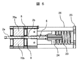
- FIG. 5 is an explanatory diagram of an external mechanism connected to the mover 6.
- an external mechanism constituted by a resonance spring 23 that is a coil spring is connected to one end of the mover 6, and the mover 6 is driven by the spring force. It is a figure explaining the mechanism in which the is returned.
- One end of the resonance spring 23 is connected to the mover 6 via the intermediate portion 24, and the other end is fixed to the base portion 25.
- a side portion 26 that extends substantially parallel to the extending direction of the resonance spring 23 and guides or supports the resonance spring 23 is provided.
- the movable element 6 (field element 6) is configured as a movable element (field element) moving type that moves in the vertical direction, but an elastic body is connected to the armature 9 instead of the movable element 6.
- the armature 9 may be configured as an armature moving type that moves the armature 9 in the vertical direction.
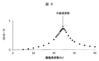
- FIG. 6 is an explanatory diagram of the relationship between the driving frequency and the stroke, and shows the relationship between the driving frequency of the AC voltage on the horizontal axis and the stroke of the mover 6 on the vertical axis.
- the amplitude of the AC voltage at each drive frequency is the same.
- the stroke of the mover 6 increases sharply near the resonance frequency, and the stroke decreases as the distance from the resonance frequency decreases.
- the resonance frequency is given by the square root of the value obtained by dividing the spring constant k of the resonance spring 23 by the mass m of the mover 6, but this value is an approximate value depending on the system of the linear motor 104.
- FIG. 7 is an explanatory diagram of the phase relationship between the position of the mover and the speed of the mover, and the phase relationship between the applied voltage and the current.
- the upper diagram in FIG. 7 shows the temporal change in the position and speed of the mover 6
- FIG. 7 shows the relationship between the applied voltage waveform and the temporal change in the current flowing through the linear motor 104.
- FIG. 8 is a diagram showing the AC waveform of FIG. 7 as a vector. It can be seen that the speed of the mover 6, the applied voltage, and the motor current are substantially in phase.
- the phase of the position of the mover 6 is the winding 8. It is known that there is a phase difference of 90 degrees with respect to the applied voltage Vm, the motor current Im, and the phase of the speed of the mover 6. That is, when any of these relationships is established, it can be estimated that the drive is performed at the resonance frequency.
- the resonance frequency changes. Moreover, when it starts from the state in which the resonant frequency changed, the stroke of the needle
- a startup sequence and a method for detecting or estimating a resonance frequency will be described.
- the control unit 102 and the like will be described with reference to FIG.
- the position detection value xm obtained by the position detection unit 106 is input to the control unit 102.
- the input position detection value xm is input to the phase difference detector 130 together with the phase command value ⁇ * generated by the control unit 102, and the phase difference estimated value dlt ⁇ ⁇ is output.
- the deviation between the phase difference command value dlt ⁇ * , which is the target value, and the phase difference estimated value dlt ⁇ ⁇ is input to the drive frequency adjuster 131.
- the drive frequency adjuster 131 outputs a frequency command value ⁇ * .
- An applied voltage based on the frequency command value ⁇ * is output to the linear motor 104.
- the position detection unit 106 As the position detection unit 106, a position sensor that detects the relative position of the mover 6 and the armature 9, a calculation unit that estimates the relative position using the applied voltage Vm, the motor current Im, or the like can be used. That is, the position detection value xm may be a detection value by the position sensor, but may also be an estimated value obtained using the applied voltage Vm or the motor current Im.
- FIG. 9 is an explanatory diagram showing the configuration of the voltage command value generator 103.
- a voltage command value generator 103 receives a phase command value ⁇ * , which will be described later, a stroke target value lref output from a host controller (not shown), and the like, and a position detection value xm.
- the command value Vm * is output. Detailed descriptions of some of the components will be described later.
- the voltage Vm * applied to the linear motor 104 can be adjusted by changing any one of the stroke command value l * , the phase command value ⁇ * , and the speed command value vm * . That is, by adjusting the amplitude and frequency of the applied voltage, the drive frequency can be controlled to the resonance frequency and the stroke can be controlled.
- a value obtained by multiplying a target value lref output from a host controller (not shown) or the like by a sine (sin ⁇ * ) of the reference phase ⁇ * is set as a position command value xm * of the mover 6.
- the phase command value ⁇ * is input to the cosine calculator 82b (the cosine of the input value is output) to obtain the cosine (cos ⁇ * ) with respect to the phase command value ⁇ * .
- the cosine, the stroke command value l *, and the frequency command value ⁇ * are multiplied by a multiplier 92d. By doing so, it is possible to obtain the speed command value vm * of the mover 6 without performing a differentiation operation.
- one of the position command value xm * and the speed command value vm * can be a sine and the other can be a cosine. Depending on the combination, it is necessary to add a negative sign, which is obvious to those skilled in the art.
- the speed command value vm * of the mover 6 is multiplied by the induced voltage constant Ke * by the multiplier 92e to obtain a single-phase AC voltage command value Vm * .
- a known synchronous motor drive voltage command method can be applied to the voltage command value generator 103.
- the stroke command generator 151, the stroke detector 152, and the stroke controller 153 will be described later.
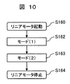
- FIG. 10 is a diagram for explaining an activation sequence when the linear motor 104 according to the present embodiment is activated.
- the activation sequence of the present embodiment includes two modes, mode (1) step S162 and mode (2) step S163.
- mode (1) control is performed so that the stroke gradually increases from substantially zero while making the drive frequency substantially constant. Thereby, it can suppress that the needle
- mode (2) first, control is performed to change the drive frequency while keeping the amplitude of the voltage substantially constant.
- the resonance frequency value fluctuates because the friction loss amount of the mover 6 fluctuates. Therefore, the fluctuation of the amplitude of the voltage can be suppressed to suppress the fluctuation of the stroke, and the resonance frequency can be easily searched.
- mode (2) control for changing the drive frequency while increasing the amplitude of the voltage is executed.
- the drive frequency can be approximated to the resonance frequency. Therefore, if the amplitude of the voltage is increased thereafter, it is easy to follow some fluctuations in the resonance frequency.
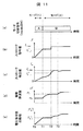
- FIG. 11 is a diagram for explaining temporal changes in main command values in each mode.
- the linear motor 104 is activated at time T0, mode (1) is activated from time T0 to time T1, and mode (2) is activated after time T1.
- the horizontal axis represents time
- the vertical axis represents the stroke command value l * , the stroke detection value lm, the applied voltage frequency (drive frequency) ⁇ * , and the applied voltage amplitude (voltage). Amplitude of command value)
- step S162 When a start command for the linear motor 104 is received from a host controller (not shown) or the like, the linear motor 104 transits to mode (1) step S162.
- the stroke command l * is monotonously increased (for example, linearly increased).
- the stroke command value l * may deviate from the stroke detection value lm depending on whether or not the drive frequency ⁇ * substantially matches the resonance frequency.
- the linear motor 104 increases the amplitude
- the drive frequency command value ⁇ * is maintained at a substantially constant value ⁇ 0.
- the initial value ( ⁇ 0) of the drive frequency output from the control unit 102 is preferably set so as to substantially match the resonance frequency of the mass spring system including the resonance spring 23, but the resonance frequency is estimated with high accuracy. Is not easy.
- the stroke command value l * is likely to deviate from the stroke detection value lm, particularly immediately after activation.
- the stroke lm of the actual mover 6 shown in FIG. 11C tends to be smaller than the stroke command l * shown in FIG. 11B.
- the load fluctuates, It can suppress that stroke lm becomes large too much.
- the amplitude of the stroke command l * or voltage command value is increased and the fluctuation of the drive frequency command value ⁇ * is suppressed immediately after startup, the initial value of the drive frequency ⁇ * matches the resonance frequency. Even if not, the actual stroke lm can be prevented from becoming excessively large.
- the stroke command l * in the mode (1) step S162 is a value ls * _1 smaller than the maximum stroke length ls_max (for example, the maximum movable length of the mover 6). This is because even when the stroke of the mover 6 becomes larger than expected, it is possible to prevent the mover 6 and the load element added to the mover 6 from being damaged.
- is, reaches the predetermined value (mode shift voltage command value Vm * 1), a transition to mode (2) Step S163.
- the time when the mode transition voltage command value Vm * 1 is reached is defined as T1.
- the mode transition voltage command value Vm * 1 can be determined as a value greater than or equal to the voltage command value that enables detection or estimation of the resonance frequency. This is because it is difficult to estimate the resonance frequency of the mover 6 unless the amplitude and speed of the mover 6 are increased to some extent.
- the mode transition voltage command value Vm * 1 can be determined by acquiring in advance the relationship between the frequency and amplitude of the voltage applied to the linear motor 104 and whether the resonance frequency can be detected or estimated. .
- step S163 the resonance frequency is detected or estimated, and the drive frequency is controlled so as to coincide with the resonance frequency.
- Stroke command value l * is maintained substantially constant.
- the stroke detection value lm is controlled to approach the stroke command value (ls * _1).
- T2 the linear motor driving apparatus 101 increases the stroke command value l * , for example, changes to the maximum stroke length ls_max.
- the stroke detection value is controlled to approach the stroke command value (ls_max).
- the stroke command value (ls_max)
- the stroke command value (ls_max)
- the load element added to the mover 6 does not change and the resonance frequency does not change
- the drive frequency can be maintained at the resonance frequency. I won't let you.
- the load element varies. In such a case, it is preferable to execute the control at the following time T3.
- the resonance frequency is detected or estimated, and the drive frequency is controlled so as to match the resonance frequency. Therefore, the drive frequency ⁇ * is controlled so as to approach the resonance frequency ⁇ res (> ⁇ 1) (the drive frequency is increased). At this time, the amplitude
- the control unit 102 illustrated in FIG. 1 uses the phase difference detector 130, the output dlt ⁇ ⁇ of the phase difference detector 130, and the phase difference command value dlt ⁇ * as the phase difference estimated value dlt ⁇ ⁇ as the phase difference command value dlt ⁇ *.
- a drive frequency adjuster 131 that adjusts the drive frequency command value ⁇ * so as to follow, an integrator 140 that integrates the drive frequency command value ⁇ * to create a phase command value ⁇ * , a phase command value ⁇ *, and
- the voltage command value generator 103 that outputs the voltage command value V * based on the stroke command value l * (stroke target value Iref) of the mover 6 is compared with the voltage command value V * and the triangular wave carrier signal.
- the PWM signal generator 133 is configured to output a drive signal for driving the output power conversion circuit 105.
- the power conversion circuit 105 may be configured to output current. In this case, a current command value generator may be provided instead of the voltage command value generator 103.
- ⁇ Reference phase generator> As for obtaining information on the relative position xm of the mover 6 and the armature 9, when using a position sensor, the output of the position sensor may be used. Therefore, a known position sensor may be used as appropriate.
- the configuration for estimating the resonance frequency from the phase difference between the phase of the mover 6 and the voltage Vm or the motor current Im applied to the winding 8 will be described.
- the reference phase reference of the mover 6 (Phase) will be described.
- the reference phase (phase command value ⁇ * ) of this embodiment is obtained by integrating the drive frequency command value ⁇ * , which is the output of the drive frequency adjuster 131 in FIG. 1, by the integrator 140 as a reference phase generator. That is, the reference phase is a phase ⁇ * of each wave having a drive frequency command value ⁇ * corresponding to the target frequency of the applied voltage Vm ( ⁇ * ).
- the integrated value of the drive frequency command value ⁇ * of the drive frequency adjuster 131 is used as the reference phase ⁇ * .
- the integrated value of the mechanical resonance frequency of the vibrating body including the mover 6 is used. It may be fixed.
- the reference phase ⁇ * can also be applied when detecting or estimating the position of the mover 6. While the drive frequency command value ⁇ * is constant, the reference phase ⁇ * is, for example, a sawtooth wave having a range of [ ⁇ , ⁇ ], [0, 2 ⁇ ] or a wider range for each time. Or may increase linearly with respect to time. As will be described later, when the drive frequency command value ⁇ * changes, the sawtooth wave and the linear increase shape change accordingly (the inclination changes).
- the reference phase ⁇ * may be obtained using the position detection value xm by the position detection unit 106.
- the position detection value xm for example, the total movement length of one-cycle displacement in which the mover 6 reciprocates is 360 °, and the reference position (for example, the midpoint of the reciprocation, the maximum or minimum position of the reciprocation)
- ⁇ Phase difference detector 130> When the mover 6 is reciprocating, the position xm of the mover 6 is a periodic function. Since the periodic function can be expressed by a Fourier series, if the position xm of the movable element 6 is expressed using a Fourier transform equation, it can be defined as the following equation (1).
- x 0 is the DC offset value
- a n and b n are the Fourier coefficients of the order n is obtained by the following formula (2) and (3).
- T 0 is the period of the fundamental wave (period in which the movable element 6 reciprocates), that is, the reciprocal of the primary frequency (drive frequency).
- the high-order component is not important, and it is only necessary to focus on the primary component, that is, the drive frequency component.
- the phase of the primary frequency component (drive frequency component) at the position xm of the mover 6 is important.
- the position xm of the mover 6 with respect to the sinusoidal applied voltage V can be obtained by the following equation (4) by the arc tangent of the first-order Fourier coefficient.
- the integration range is -2 ⁇ to 0. This is because when the phase difference detector 130 is realized by a semiconductor integrated circuit such as a microcomputer or a DSP (Digital Signal Processor), only past information can be acquired.
- a semiconductor integrated circuit such as a microcomputer or a DSP (Digital Signal Processor)
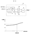
- FIG. 12 is an explanatory diagram of a configuration example of the phase difference detector and a relationship between the driving frequency and the phase difference detector output
- the upper diagram of FIG. 12 is an explanatory diagram when Expression (4) is shown in a block diagram.
- 12 is an explanatory diagram of the relationship between the drive frequency and the output of the phase difference detector 130.
- the phase command value ⁇ * is input to the sine calculator 81 (outputs the sine of the input value) and the cosine calculator 82 (outputs the cosine of the input value), respectively, to obtain the sine and cosine for the phase command value ⁇ * .
- a value obtained by multiplying each of the sine and cosine by the position xm of the mover 6 is output from the multiplier 92.
- the outputs of the integrators 94 a and 94 b are input to the arc tangent device 86.
- the arc tangent unit 86 outputs an arc tangent value based on the input sine and cosine components.
- the arc tangent unit 86 of this embodiment outputs an arc tangent value of the phase with the numerator as the output of the integrator 94a and the denominator as the output of the integrator 94b, but even if a value obtained by reversing the numerator and denominator is output. good.
- FIG. 12 is a diagram showing the relationship between the frequency of the AC voltage (horizontal axis) and the output value (phase difference dlt ⁇ ⁇ ) (vertical axis) of the arc tangent device 86.
- 90 ° is output from the arc tangent device 86 when the drive frequency matches the resonance frequency.
- the value output from the arc tangent device 86 is greater than 90 ° when the drive frequency is higher than the resonance frequency, and less than 90 ° when the drive frequency is lower than the resonance frequency.
- the phase difference dlt ⁇ ⁇ of the primary frequency component of the AC signal input to the phase difference detector 130 with respect to the reference phase ⁇ * (in this embodiment, the position xm of the mover 6) can be obtained.
- Estimation is possible. For example, when the phase difference dlt ⁇ ⁇ exceeds 90 °, the phase difference dlt ⁇ ⁇ is controlled so as to decrease, and when it is less than 90 °, the control may be performed so as to increase. It is preferable to control the phase difference dlt ⁇ ⁇ when the reference phase ⁇ * and the fundamental frequency ⁇ have the same value as the target value dlt ⁇ * .
- An incomplete integrator can be used in place of the integrators 94a and 94b.
- the incomplete integrator is a kind of low-pass filter and can be configured similarly to the first-order lag filter.
- a high-pass filter (not shown) can be provided before the integrators 94a and 94b (or the incomplete integrator).
- the cutoff frequency of the high-pass filter can be set to 10 or 5 Hz or less, for example.
- the phase difference detector 130 uses the arc tangent of the ratio of the first-order Fourier coefficient of the drive frequency component to determine the phase ⁇ of the position xm of the mover 6 with respect to the AC voltage command value V * .
- Only the primary frequency component of the AC signal input to the detector 130 has high sensitivity. That is, for example, even when a DC offset or higher-order noise is superimposed on the position xm of the mover 6, the phase dlt ⁇ of the primary frequency component of the AC signal input to the phase difference detector 130 with respect to the reference phase ⁇ * . Is required more accurately.
- the high-pass filter is provided as described above, it can be configured to be robust with respect to a frequency smaller than the drive frequency ⁇ .
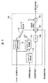
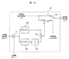
- FIG. 13 is a diagram illustrating a configuration example of the drive frequency adjuster 131.
- the frequency command switch 155 switches between the two inputs according to a mode switching signal (modeSW) that is a command for switching between the mode (1) and the mode (2).
- mode (1) step S162 the value input to the A side of the frequency command switch 155 is output. That is, the initial value ( ⁇ 0 ) of the drive frequency command is output as it is as the frequency command value ⁇ * .
- mode (2) step S163 the value input to the B side of the frequency command switch 155 is output. The value input to the B side is determined as follows.
- the drive frequency adjuster 131 obtains a difference between the phase difference command value dlt ⁇ * (for example, 90 °) and the phase difference dlt ⁇ ⁇ obtained by the phase difference detector 130 by the subtractor 91, and a multiplier 92b supplies the difference to the proportional gain Kp_adtr. Is multiplied by the integration gain Ki_adtr by the multiplier 92c, and the result of integration control by integrating the result by the integrator 94c is added by the adder 90 to obtain the drive frequency command value ⁇ * . Output.
- the phase difference command value dlt ⁇ * may be obtained from a host controller (not shown in the present embodiment), or may be set to 90 ° in advance as in the present embodiment.
- the drive frequency adjuster 131 of the present embodiment has a configuration of proportional integral control, but other control configurations such as proportional control and integral control can also be applied.
- phase difference detector 130 and the drive frequency adjuster 131 when the linear motor 104 is driven at a mechanical resonance frequency determined from the mass of the mover 6 and the spring constant will be described.
- the actual resonance frequency is lower than the design value. That is, when the initial value of the drive frequency is determined using the mass design value of the mover 6 (when the initial value of the drive frequency command value ⁇ * is determined using the design value), the actual resonance frequency is used. Drive at a high frequency. At this time, the phase difference dlt ⁇ ⁇ obtained by the phase difference detector 130 is larger than the phase difference command value dlt ⁇ * .
- the drive frequency adjuster 131 executes control to decrease the drive frequency command value ⁇ *, and as a result, the drive frequency command value ⁇ * matches the actual resonance frequency. Therefore, the velocity energy of the mover 6 can be effectively used, and the linear motor 104 can be driven with high efficiency.
- the voltage command value generator 103 receives the phase command value ⁇ * and the stroke command value l * , and outputs a single-phase AC voltage command value Vm * . Details will be described below.
- the stroke command switch 150 switches between the two inputs in accordance with the mode switching signal (modeSW) shown in FIG.
- the voltage applied to the linear motor 104 can be adjusted by changing any one of the stroke command value l * , the phase command value ⁇ * , and the speed command value vm * . That is, by adjusting the amplitude and frequency of the applied voltage, the drive frequency can be controlled to the resonance frequency and the stroke can be controlled.
- step S162 the output value of the stroke command generator 151 input to the A side of the stroke command switch 150 (see FIG. 9 etc.) is output.
- FIG. 14 is a diagram illustrating the configuration of the stroke command generator 151.
- start signal start signal (MtrStart)
- the output of the start signal switch 160 changes from 0 to 1 according to the start command.
- the output of the start signal switch 160 is divided by the stroke increase rate calculator 161 by the arrival time (T_inc) to the stroke target value Iref, multiplied by the stroke target value Iref by the multiplier 162, and the multiplied value is multiplied by the integrator 163. Integrate.
- a signal having an inclination of Iref / T_inc is obtained.
- the limiter 164 limits the value to the limit value input (stroke target value Iref in the example of FIG. 14), and obtains the stroke command value l * _A.
- the output value of the stroke controller 153 input to the B side of the stroke command switch 150 (FIG. 9) is output.
- the stroke controller 153 receives the output of the stroke detector 152 and the like.
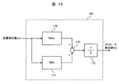
- FIG. 15 is a diagram illustrating a configuration example of the stroke detector 152.
- the maximum value detector 170 and the minimum value detector 171 are the maximum values of input values (in the example of FIG. 15, position detection value xm) in a predetermined period (for example, [0, 2 ⁇ ] period of the reference phase ⁇ * ). And the minimum value is output. After adding both by the adder 172, the multiplier 173 multiplies by 1/2, and the stroke detection value lm is obtained.
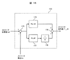
- FIG. 16 is a diagram illustrating a configuration example of the stroke controller 153.
- the stroke controller 153 obtains a difference between the stroke target value lref and the stroke detection value lm obtained by the stroke detector 152 by a subtractor 175, and multiplies the result by a proportional gain Kp_stl by a multiplier 176,
- the multiplier 177 multiplies the integral gain Ki_stl and integrates the result by the integrator 178, and the result of integration control is added by the adder 179, and the stroke command value l * _B is output.
- the PWM signal generator 133 generates a drive signal corresponding to the voltage command value Vm * using known pulse width modulation by comparing the triangular wave carrier signal and the voltage command value Vm * .
- FIG. 17 is a diagram illustrating a configuration example including the power conversion circuit 105.
- the full bridge circuit 126 switches the DC voltage source 120 according to the drive signal input from the control unit 102 and outputs a voltage to the linear motor 104.
- the full bridge circuit 126 includes four switching elements 122, a first upper and lower arm (hereinafter referred to as U phase) having switching elements 122a and 122b connected in series, and a second upper and lower arm having switching elements 122c and 122d. Arm (hereinafter referred to as V phase).
- the switching element 122 can perform a switching operation according to a pulsed gate signal (124a to 124d) output from the gate driver circuit 123 based on a voltage command value generated by the control unit 102 or a drive signal by pulse width modulation. By controlling the conduction state (ON / OFF) of the switching element 122, a voltage corresponding to the AC voltage of the DC voltage source 120 can be output to the winding 8. Note that a DC current source may be used instead of the DC voltage source 120.
- a semiconductor switching element such as IGBT or MOS-FET can be employed.
- the linear motor 104 is connected between the switching elements 122 a and 122 b of the first upper and lower arms and between the switching elements 122 c and 122 d of the second upper and lower arms of the power conversion circuit 105.
- FIG. 17 shows an example in which the windings 8 of the upper and lower armatures 9 are connected in parallel, the windings 8 can also be connected in series.
- a current detector 107 such as a CT (current transformer) can be provided on the U-phase lower arm and the V-phase lower arm. Thereby, the current Im flowing through the winding of the linear motor 104 can be detected.
- a phase shunt current method is adopted in which a shunt resistor 125 is added to the lower arm of the power conversion circuit 105 and the current flowing to the linear motor 104 is detected from the current flowing to the shunt resistor 125. it can.
- a single shunt current detection method for detecting the current on the AC side of the power conversion circuit 105 from the DC current flowing through the shunt resistor 125 added to the DC side of the power conversion circuit 105 is used. It may be adopted.
- the single shunt current detection method utilizes the fact that the current flowing through the shunt resistor 125 changes with time depending on the energization state of the switching element 122 constituting the power conversion circuit 105.
- the mode transition voltage command value Vm * 1 is a value obtained by multiplying a ratio in the DC voltage source 120 of the power conversion circuit, a ratio between the induced voltage of the linear motor 104 and the DC voltage source 120 of the power conversion circuit, or Further, it can be determined by the ratio of the position xm of the movable element 6 to the maximum stroke length of the movable element 6.
- the operation mode (1) in which the frequency of the AC voltage is kept substantially constant and the amplitude is monotonously increased, and the phase difference between the AC voltage of the mover and the mover position is obtained.
- the operation mode (2) for changing the frequency of the AC voltage so that the phase difference becomes a predetermined value while keeping the stroke of the stroke constant is desired, so that the stroke of the mover 6 is desired regardless of the load at the time of startup. Stable start-up can be achieved by controlling the stroke. Since the present embodiment can produce an effect corresponding to a mass deviation or the like of a mover or the like, it is effective even when the load does not fluctuate.
- the configuration of the present embodiment can be the same as that of the first embodiment except for the following points.
- the resonance frequency is estimated using the motor current Im
- the relative position is estimated using the applied voltage Vm, the motor current Im, and the like.
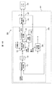
- FIG. 18 is an overall schematic configuration diagram of a linear motor system 200 of Example 2 according to another example of the present invention.
- the linear motor system 200 includes a linear motor driving device 201 and a linear motor 104.
- the linear motor driving device 201 includes at least a control unit 202 having a position estimation unit 208 and a phase difference detector 230, a current detector 207, and a power conversion circuit 105.
- FIG. 19 is an explanatory diagram illustrating a configuration example of the phase difference detector 230 of the present embodiment.
- the phase command value ⁇ * (reference phase ⁇ * ) is input to the sine calculator 81 (outputs the sine of the input value) and the cosine calculator 82 (outputs the cosine of the input value), respectively, and the phase command value ⁇ * (reference phase) Obtain the sine and cosine for ⁇ * ).
- a value obtained by multiplying each of the sine and cosine by the motor current Im is output from the multiplier 92.
- first-order lag filters 141a and 141b which are examples of lag filters
- first-order Fourier coefficients of sine and cosine are obtained. That is, since higher-order frequency components can be eliminated from the drive frequency ⁇ of the Fourier expansion, it can be configured robustly against higher-order noise.
- the outputs of the first-order lag filters 141 a and 141 b are input to the arc tangent device 86.
- the arc tangent unit 86 outputs an arc tangent value based on the input sine and cosine components.
- the arc tangent unit 86 of this embodiment outputs an arc tangent value of the phase with the numerator as the negative value of the output of the first order lag filter 141a and the denominator as the output of the first order lag filter 141b.
- a value obtained by inverting the numerator and the denominator may be output.
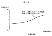
- FIG. 20 is a diagram showing the relationship between the drive frequency (horizontal axis) of the AC voltage and the output value (phase difference dlt ⁇ ) (vertical axis) of the arc tangent device 86.
- the drive frequency when the drive frequency is the resonance frequency, 0 ° is output from the arc tangent device 86.
- the value output from the arc tangent device 86 is greater than 0 ° when the drive frequency is higher than the resonance frequency, and less than 0 ° when the drive frequency is lower than the resonance frequency.
- phase difference dlt ⁇ of the primary frequency component of the AC signal input to the phase difference detector 230 with respect to the reference phase ⁇ * (in this embodiment, the position xm of the mover 6) can be obtained, and the resonance frequency is estimated. Is possible.
- the position estimation unit 208 estimates the position of the mover 6. For example, using the voltage Vm applied to the linear motor 104 and the current Im flowing through the linear motor 104, for example, the position estimated value xm ⁇ is obtained by the following equation (5).
- Vm * is a voltage command value Vm * applied to the linear motor 104.
- FIG. 21 is an explanatory diagram illustrating a configuration example of the position estimation unit 208, and is an explanatory diagram when Expression (5) is illustrated in a block diagram.
- a known synchronous motor position estimation method can be applied to the position estimation unit 208. If the estimated position value xm ⁇ is input to the stroke detector 152 of FIG. 15, the desired stroke can be controlled.
- the position of the mover 6 is estimated from the voltage applied to the linear motor 104 and the current flowing through the linear motor 104, and the resonance frequency is detected with high accuracy based on the estimated position value.
- high-efficiency linear motor driving can be provided by estimation.
- the operation mode (1) in which the frequency of the AC voltage is kept constant and the amplitude is monotonously increased, the phase difference between the AC voltage of the mover and the mover position is obtained, and the phase difference is maintained while keeping the stroke of the mover constant.
- the operation mode (2) for changing the frequency of the AC voltage so that the value becomes a predetermined value, the 6 strokes of the mover are controlled to a desired stroke regardless of the load at the time of startup, and stable startup is achieved.
- Realizable linear motor drive can be realized.
- the configuration of this embodiment can be the same as that of Embodiment 1 or 2 except for the following points.
- the present embodiment relates to a hermetic compressor 50 as an example of a device on which the linear motor system 100 is mounted.
- the device it is possible to use a device that applies a load that varies according to the phase ⁇ or the driving frequency ⁇ to the reciprocating vibrating body (movable element 6).
- FIG. 22 is a longitudinal sectional view of a hermetic compressor according to a third embodiment of the present invention, and is an example of a longitudinal sectional view of a hermetic compressor 50 having a linear motor 104.
- the hermetic compressor 50 is a reciprocating compressor in which the compression element 20 and the electric element 30 are arranged in the hermetic container 3.
- the compression element 20 and the electric element 30 are elastically supported in the sealed container 3 by a support spring 49.
- the electric element 30 includes a mover 6 and an armature 9.
- the compression element 20 includes a cylinder block 1 that forms a cylinder 1a, a cylinder head 16 that is assembled to an end face of the cylinder block 1, and a head cover 17 that forms a discharge chamber space.
- the working fluid supplied into the cylinder 1a is compressed by the reciprocating motion of the piston 4, and the compressed working fluid is sent to a discharge pipe (not shown) communicating with the outside of the compressor.
- a piston 4 is attached to one end of the mover 6.
- the movable body 6 and the piston 4 reciprocate to compress and expand the working fluid. This corresponds to a load in which work required for compression and expansion fluctuates.
- a compression element 20 is disposed at one end of the electric element 30.
- the cylinder block 1 has a guide rod that guides the reciprocating motion of the mover 6 along the front-rear direction.
- the linear motor system 300 (FIG. 23) of the present embodiment estimates the position of the mover 6 from the voltage Vm applied to the linear motor 104 and the motor current Im flowing through the linear motor 104, and obtains the position estimated value xm ⁇ . Based on this, the resonance frequency is detected or estimated with high accuracy to provide a highly efficient linear motor drive.
- the resonance frequency is a mechanical resonance determined from the mass of the mover 6 and the spring constant. Close to frequency. If the resonance frequency is estimated without considering the pressure in the cylinder 1a, the stroke of the mover 6 becomes larger than expected, and the piston 4 may collide with the cylinder head 16. When the piston 4 collides with the cylinder head 16, it not only makes noise, but in the worst case, the piston 4 and the cylinder head 16 may be damaged. For this reason, it is desirable to appropriately control the stroke even during a transition such as startup.
- the linear motor system 300 of the present embodiment estimates the position of the mover 6 from the voltage applied to the linear motor 104 and the current flowing through the linear motor 104, and based on the estimated position value. It is possible to detect or estimate the resonance frequency with high accuracy and realize a highly efficient linear motor drive.
- the position of the mover 6 can be estimated based on the applied voltage Vm and the motor current Im, it is possible to reduce the necessity of arranging a position sensor in the sealed container 3 that is a high temperature and high pressure environment. Also, no load (suction pressure and discharge pressure of the pressure element 20) can be obtained by appropriately switching the control gain according to the load of the linear motor 104 (eg, proportional to the difference between the suction pressure and the discharge pressure of the pressure element 20). Linear motor drive that can be stably started and driven even under a wide range of load conditions such as (equal pressure state) to heavy load.
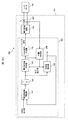
- FIG. 23 is an overall schematic configuration diagram of the linear motor system 300 of the present embodiment.
- the linear motor system 300 includes a linear motor driving device 301 and a linear motor 104.
- the linear motor driving device 301 includes at least a control unit 302 having a position estimation unit 308 and a phase difference detector 330, a current detector 307, and a power conversion circuit 105.
- FIG. 24 is a diagram for explaining temporal changes in main command values in each activation sequence.
- a gain switching signal (gainSW) is added compared to FIG.
- the gain switching signal (gainSW) switches the control gain of each controller (for example, the stroke controller 353 shown in FIG. 25) according to the state (H or L).
- the control gain in state H is greater than the control gain in state L.
- the state at heavy load can be set to state H and the state at no load or light load can be set to state L.
- the light load may be set to focus on short-term fluctuations in which the working fluid expands lightly and the working fluid compresses heavily, or the load is relatively light and the load is relatively heavy It may be a setting that pays attention to long-term fluctuation with a heavy load.
- the determination of light load and heavy load can be made by obtaining in advance information on the resonance frequency when the hermetic compressor 50 is unloaded and comparing it. Specifically, since the resonance frequency decreases when the load is large, the weight of the load can be estimated by examining how much the resonance frequency is different from the resonance frequency at the time of no load.
- the resonance frequency be controlled in a short time when starting up.
- the control gain for example, the proportional gain Kp_stl shown in FIG. 25
- the control gain is increased more than necessary, there is a problem that it becomes oscillating in a steady state (a state where the difference from the command value is small).
- FIG. 25 is a diagram illustrating the configuration of the stroke controller 353 of the present embodiment.
- the gain switch 360 switches the control gains (proportional gain Kp_stl and integral gain Ki_stl) of the multiplier 376 and the multiplier 377 according to the state (H or L) of the gain switch signal (gainSW).
- the state H immediately after activation is set to the state H, and the change rate (time differential value) of the voltage amplitude is increased. Therefore, the mode (1) is easily executed and the mode (2) is easily changed.
- the gain switching signal is switched from H to L at time T2 during execution of mode (2). In the initial start up to time T2, depending on the condition of the compression element 20, the difference between the drive frequency and the resonance frequency is large.
- the required flow rate of the compression element 20 (determined by the product of the stroke and the drive frequency) is changed (decreased) from the host controller (not shown) or the like, and the stroke command value l * decreases. It is the moment that was done. In this case, after the stroke detection value lm reaches the stroke command value (ls * _2), the resonance frequency starts to be affected by the compression element 20, and the resonance frequency is lowered. In this case, if the drive frequency is increased by the drive frequency adjuster 131 more than necessary, the drive frequency may not be stabilized. Therefore, similarly, the drive frequency adjuster 131 is also configured with a gain switch 360 (see FIG. 25, etc.), which is shown in FIG.
- the position of the mover 6 is estimated from the voltage applied to the linear motor 104 and the current flowing through the linear motor 104, and the resonance frequency is detected with high accuracy based on the estimated position value.
- highly efficient linear motor driving can be realized by estimation.
- the operation mode (1) in which the frequency of the AC voltage is kept constant and the amplitude is monotonously increased, the phase difference between the AC voltage of the mover and the mover position is obtained, and the phase difference is maintained while keeping the stroke of the mover constant.
- the stroke of the mover 6 is controlled to a desired stroke regardless of the load at the time of startup, and stable startup is realized.
- a linear motor drive can be provided. Also, no load (suction pressure and discharge pressure of the pressure element 20) can be obtained by appropriately switching the control gain according to the load of the linear motor 104 (eg, proportional to the difference between the suction pressure and the discharge pressure of the pressure element 20).
- Linear motor drive that can be stably started and driven even under a wide range of load conditions such as a pressure equalization state) to a heavy load.
- the compressor shown in this embodiment can be applied to a compressor for pumping refrigerant in an air conditioner including a heat exchanger functioning as a condenser or an evaporator.
- the linear motor driving device that controls the driving of the compressor the linear motor driving device shown in the first embodiment or the second embodiment described above can be employed.
- the compressor shown in the present embodiment can be applied to a compressor that compresses a working fluid in order to adjust the vehicle height in an air suspension.
- the linear motor driving device that controls the driving of the compressor the linear motor driving device shown in the first embodiment or the second embodiment described above can be employed.
- the compressor shown in the present embodiment can also be applied to a compressor that pumps liquid refrigerant in a refrigerator having a condenser and an evaporator.
- the linear motor driving device that controls the driving of the compressor the linear motor driving device shown in the first embodiment or the second embodiment described above can be employed.
- the present invention is not limited to the above-described embodiments, and includes various modifications.
- the above-described embodiments have been described in detail for easy understanding of the present invention, and are not necessarily limited to those having all the configurations described.
- Each of the above-described configurations, functions, processing units, processing procedures, and the like may be realized by hardware by designing a part or all of them with, for example, an integrated circuit.
- Each of the above-described configurations, functions, and the like may be realized by software by interpreting and executing a program that realizes each function by the processor.
Landscapes
- Engineering & Computer Science (AREA)
- Power Engineering (AREA)
- Physics & Mathematics (AREA)
- Chemical & Material Sciences (AREA)
- Combustion & Propulsion (AREA)
- Electromagnetism (AREA)
- Mechanical Engineering (AREA)
- General Engineering & Computer Science (AREA)
- Control Of Linear Motors (AREA)
- Compressors, Vaccum Pumps And Other Relevant Systems (AREA)
- Linear Motors (AREA)
Abstract
起動直後の共振周波数の推定精度を向上し得るリニアモータ制御装置及びこれを搭載した圧縮機を提供する。交流電圧が印加される巻線と、弾性体が接続する可動子と、を備えるリニアモータ制御装置であって、交流電圧の周波数を略一定に保ちつつ交流電圧の振幅を単調増加させる運転モード(1)と、交流電圧の振幅を略一定に保ちつつ、交流電圧の周波数を変化させる運転モード(2)と、を有し、運転モード(1)、運転モード(2)の順で実行する。
Description
本発明は、リニアモータ制御装置及びこれを搭載した圧縮機に関する。
弾性体を接続させた可動子を、弾性体及び可動子の系における機械的な共振周波数で駆動させるリニアモータが知られている。機械的な共振周波数は、可動子の摩擦や、可動子に接続する負荷に応じて変動するため、共振周波数を効果的に推定することが望まれる。
例えば、特許文献1は、サーチコイルからの誘起電圧の位相を検出し、リニアモータに流れる電流位相との位相差を検出し、位相差に応じてピストンの共振周波数に一致させる構成が開示されている。また、特許文献1には、出力電圧の周波数に応じた値だけ出力電圧の電圧値を補正してピストンのストロークを一定に保持する構成が記載されている。
例えば、特許文献1は、サーチコイルからの誘起電圧の位相を検出し、リニアモータに流れる電流位相との位相差を検出し、位相差に応じてピストンの共振周波数に一致させる構成が開示されている。また、特許文献1には、出力電圧の周波数に応じた値だけ出力電圧の電圧値を補正してピストンのストロークを一定に保持する構成が記載されている。
特許文献1は、リニアコンプレッサーの巻線にサーチコイルを具備し、誘起電圧の位相を検出している。しかしながら、サーチコイルを用いると配線が煩雑になるだけでなく、ノイズの影響を受けやすくなるため、高精度に共振周波数に制御することは容易ではない。また、起動時のように、早期に可動子振幅を確保してリニアモータの立ち上がりを行わせるのに適した制御については何ら考慮されていない。
そこで、本発明は、起動直後の共振周波数の推定精度を向上し得るリニアモータ制御装置及びこれを搭載した圧縮機を提供する。
上記課題を解決するため、本発明のリニアモータ制御装置は、交流電圧が印加される巻線と、弾性体が接続する可動子と、を備えるリニアモータ制御装置であって、前記交流電圧の周波数を略一定に保ちつつ前記交流電圧の振幅を単調増加させる運転モード(1)と、前記交流電圧の振幅を略一定に保ちつつ、前記交流電圧の周波数を変化させる運転モード(2)と、を有し、前記運転モード(1)、前記運転モード(2)の順で実行することを特徴とする。
また、本発明の圧縮機は、交流電圧が印加される巻線と、弾性体が接続する可動子と、を備えるリニアモータ制御装置を有する圧縮機であって、前記リニアモータ制御装置は、前記交流電圧の周波数を略一定に保ちつつ前記交流電圧の振幅を単調増加させる運転モード(1)と、前記交流電圧の振幅を略一定に保ちつつ、前記交流電圧の周波数を変化させる運転モード(2)と、を有し、前記運転モード(1)、前記運転モード(2)の順で実行すると共に、前記可動子の位置を、前記巻線の電圧及び電流値を利用して推定することを特徴とする。
また、本発明の圧縮機は、交流電圧が印加される巻線と、弾性体が接続する可動子と、を備えるリニアモータ制御装置を有する圧縮機であって、前記リニアモータ制御装置は、前記交流電圧の周波数を略一定に保ちつつ前記交流電圧の振幅を単調増加させる運転モード(1)と、前記交流電圧の振幅を略一定に保ちつつ、前記交流電圧の周波数を変化させる運転モード(2)と、を有し、前記運転モード(1)、前記運転モード(2)の順で実行すると共に、前記可動子の位置を、前記巻線の電圧及び電流値を利用して推定することを特徴とする。
本発明によれば、起動直後の共振周波数の推定精度を向上し得るリニアモータ制御装置及びこれを搭載した圧縮機を提供することが可能となる。
上記した以外の課題、構成及び効果は、以下の実施形態の説明により明らかにされる。
上記した以外の課題、構成及び効果は、以下の実施形態の説明により明らかにされる。
以下、添付の図面を参照しつつ本発明の実施例を詳細に説明する。同様の構成要素には同様の符号を付し、重複する説明を省略する。
本発明の各種の構成要素は、必ずしも個々に独立した存在である必要はなく、複数の構成要素が一個の部材として形成されていること、一つの構成要素が複数の部材で形成されていること、或る構成要素が他の構成要素の一部であること、或る構成要素の一部と他の構成要素の一部とが重複していること、等を許容する。
本発明の各種の構成要素は、必ずしも個々に独立した存在である必要はなく、複数の構成要素が一個の部材として形成されていること、一つの構成要素が複数の部材で形成されていること、或る構成要素が他の構成要素の一部であること、或る構成要素の一部と他の構成要素の一部とが重複していること、等を許容する。
本実施例では、説明の便宜上、互いに直交する前後方向、左右方向、及び上下方向という語を用いるが、重力方向は必ずしも下方向に平行である必要はなく、前後方向、左右方向、上下方向又はそれ以外の方向に平行にすることができる。
<リニアモータ駆動装置101>
図1は、本発明の一実施例に係る実施例1のリニアモータシステム100の全体概略構成図である。リニアモータシステム100は、リニアモータ駆動装置101と、リニアモータ104とから構成される。後述するようにリニアモータ104は、相対移動する電機子9及び可動子6を有する。
リニアモータ駆動装置101は、位置検出部106と、制御部102と、電力変換回路105を有する。
位置検出部106は、電機子9に対する可動子6の相対位置(可動子位置)を検出する。本実施例では、可動子6が鉛直方向に移動するが、電機子9及び可動子6(界磁子)が相対移動すれば良く、電機子9が鉛直方向に移動する態様でも良い。なお、以下では、可動子6が鉛直方向に往復運動する場合を一例として説明するが、往復運動の方向は鉛直方向に限られるものではない。例えば、可動子6が水平方向に往復運動するよう構成しても良く、また、鉛直方向に対し任意の角度を有する方向に可動子6が往復運動する構成としても良い。また、これらは、電機子9につても同様である。
制御部102は、位置検出部106の検出結果に応じて、電力変換回路105への出力電圧指令値、又は電力変換回路105を駆動するドライブ信号(パルス信号)を出力する。
詳細は後述するが、電力変換回路105は、直流電圧源120の電圧を変換して交流電圧を出力する電力変換部の一例である。なお、直流電圧源120に代えて直流電流源を用いても良い。
<リニアモータ104>
図2はリニアモータ104の斜視図(電機子の構成例の斜視図)である。本実施例のリニアモータ104は、電機子9に対して、永久磁石2(2a,2b)が並んだ方向(前後方向)に相対移動可能な可動子6を有する。電機子9は空隙を介して上下方向に対向する2つの磁極7と、磁極7に捲回された巻線8とを有している。可動子6は、この空隙に配置されている。磁極7は、可動子6に対向する端面としての磁極歯70を有している。
電機子9は、可動子6に対して前後方向の力(以下、推力と称する)を付与できる。例えば、後述するように、可動子6が前後方向に往復運動するように推力を制御できる。
可動子6は、上下方向に磁化した2つの平板状の永久磁石2(2a,2b)を有している。後側の永久磁石2a及び前側の永久磁石2bは、互いに反対方向に磁化されている。本実施例では、後側の永久磁石2aは上側にN極を有し、前側の永久磁石2bは上側にS極を有している。図2では、永久磁石2a,2bは図示しているが、可動子6は図示していない。可動子6としては、例えば、平板状の永久磁石2を固定した平板状のものを採用できる。
制御部102は、可動子6を永久磁石2a,2bが電機子9に対向する範囲で往復運動させるようにドライブ信号を出力する。
図3は、図2のA-A’線に沿った平面での断面図である(A―A’断面矢視図)。図3の矢印線は、2つの巻線8に電流を流したときの磁束線の一例を示している。磁束の流れの向きは、巻線8に流れる電流の向きにより逆方向になり得るため、図に示す限りではない。この磁束線により、磁極歯70が磁化される。
[可動子6に付与する推力]
図4は磁極歯70の磁化により、可動子6が受ける推力を説明する図である。巻線8に流れる電流により生じる磁極歯70の極性を、図中の磁極歯70近傍に付した「N」、「S」で表している。また、図4において白抜き矢印は巻線8を流れる電流の向きを示している。図4の左図は、巻線8を流れる電流により、上側の磁極歯70aが「S」、下部の磁極歯70bが「N」に磁化されることにより、可動子6が前方向に力を受け、可動子6が前に移動した例を示している。図4の右図は、巻線8を流れる電流により、上部の磁極歯70aが「N」、下部の磁極歯70bが「S」に磁化されることにより、可動子6が後ろ方向に力を受け、可動子6が後ろに移動した例を示している。
図4は磁極歯70の磁化により、可動子6が受ける推力を説明する図である。巻線8に流れる電流により生じる磁極歯70の極性を、図中の磁極歯70近傍に付した「N」、「S」で表している。また、図4において白抜き矢印は巻線8を流れる電流の向きを示している。図4の左図は、巻線8を流れる電流により、上側の磁極歯70aが「S」、下部の磁極歯70bが「N」に磁化されることにより、可動子6が前方向に力を受け、可動子6が前に移動した例を示している。図4の右図は、巻線8を流れる電流により、上部の磁極歯70aが「N」、下部の磁極歯70bが「S」に磁化されることにより、可動子6が後ろ方向に力を受け、可動子6が後ろに移動した例を示している。
このように、巻線8に電圧や電流を印加することで、2つの磁極7を含む磁気回路に磁束を供給して、対向する2つの磁極歯70(磁極歯組)を磁化できる。電圧や電流として、例えば正弦波や矩形波(方形波)といった交流の電圧や電流を与えることで、可動子6を往復運動させる推力を与えることができる。これにより可動子6の運動を制御できる。
なお、可動子6に付与する推力は、印加する交流電流や交流電圧の振幅を変更することで変えられる。また、可動子6に付与する推力を公知の方法を用いて適切に変更することで、可動子6の変位を所望に変えられる。ここで、可動子6が往復運動(例えば、図4の左図及び右図のような磁極歯70の磁化を順次繰り返すことで可動子6に生じる運動)をする場合、交流波形的に変化する可動子6の変位の変化量をストロークと呼ぶ。
磁極歯70は磁性体であるため、永久磁石2を吸引する磁気吸引力が作用する。本実施例では可動子6を挟むよう間隙を介して2つの磁極歯70を対向配置しているため、可動子6に作用する磁気吸引力の合力を低減できる。
磁極歯70は磁性体であるため、永久磁石2を吸引する磁気吸引力が作用する。本実施例では可動子6を挟むよう間隙を介して2つの磁極歯70を対向配置しているため、可動子6に作用する磁気吸引力の合力を低減できる。
[可動子6外部の機構]
図5は、可動子6に接続される外部機構の説明図であり、例えば、コイルバネである共振バネ23によって構成される外部機構を可動子6の一端に接続し、そのバネ力により可動子6が戻される機構を説明する図である。共振バネ23は、一端が中間部24を介して可動子6に接続し、他端が基部25に固定されている。また、共振バネ23の延在方向と略平行に延在し、共振バネ23を案内又は支持する側部26が設けられている。リニアモータ104を往復運動させる場合、可動子6の運動方向が変わる度に、加速と減速を繰り返す。減速時は、可動子6の速度エネルギーが電気エネルギーに変換される(回生動作)が、リニアモータ104への配線の抵抗によって損失が生じる。一方、図5のように、可動子6に共振バネ23(アシストバネ)を付加し、可動子6の質量とバネ定数から決まる機械的な共振周波数で、可動子6を往復運動させる場合、可動子6の速度エネルギーを有効活用でき、高効率なリニアモータ駆動システムを構成することができる。共振バネ23に代えて、公知の弾性体を用いてもよい。このように構成すると、可動子6(界磁子6)が鉛直方向に移動する可動子(界磁子)移動型として構成されるが、可動子6に代えて電機子9に弾性体を接続して電機子9を鉛直方向に移動させる電機子移動型として構成しても良い。
図5は、可動子6に接続される外部機構の説明図であり、例えば、コイルバネである共振バネ23によって構成される外部機構を可動子6の一端に接続し、そのバネ力により可動子6が戻される機構を説明する図である。共振バネ23は、一端が中間部24を介して可動子6に接続し、他端が基部25に固定されている。また、共振バネ23の延在方向と略平行に延在し、共振バネ23を案内又は支持する側部26が設けられている。リニアモータ104を往復運動させる場合、可動子6の運動方向が変わる度に、加速と減速を繰り返す。減速時は、可動子6の速度エネルギーが電気エネルギーに変換される(回生動作)が、リニアモータ104への配線の抵抗によって損失が生じる。一方、図5のように、可動子6に共振バネ23(アシストバネ)を付加し、可動子6の質量とバネ定数から決まる機械的な共振周波数で、可動子6を往復運動させる場合、可動子6の速度エネルギーを有効活用でき、高効率なリニアモータ駆動システムを構成することができる。共振バネ23に代えて、公知の弾性体を用いてもよい。このように構成すると、可動子6(界磁子6)が鉛直方向に移動する可動子(界磁子)移動型として構成されるが、可動子6に代えて電機子9に弾性体を接続して電機子9を鉛直方向に移動させる電機子移動型として構成しても良い。
図6は、駆動周波数とストロークの関係の説明図であり、交流電圧の駆動周波数を横軸に、可動子6のストロークを縦軸にとり、これらの関係を示す図である。各駆動周波数における交流電圧の振幅は同一である。図6から分かるように、共振周波数付近で可動子6のストロークが急峻に大きくなり、共振周波数から離れるとストロークが小さくなる特性を示す。共振周波数は、共振バネ23のバネ定数kを可動子6の質量mで除した値の平方根で与えられるが、リニアモータ104の系によっては、この値は近似値となる。
このように、共振周波数又はこの近傍の駆動周波数の交流電圧を印加することで、大きなストローク(大きなエネルギー)で振動させることができる。つまり、可動子6に共振バネ23等の弾性体を付加したリニアモータ104を制御する場合には、可動子6の共振周波数を検出あるいは推定することが重要である。可動子6のストロークを所望に制御する場合においても可動子6の共振周波数を検出あるいは推定することが重要である。
このように、共振周波数又はこの近傍の駆動周波数の交流電圧を印加することで、大きなストローク(大きなエネルギー)で振動させることができる。つまり、可動子6に共振バネ23等の弾性体を付加したリニアモータ104を制御する場合には、可動子6の共振周波数を検出あるいは推定することが重要である。可動子6のストロークを所望に制御する場合においても可動子6の共振周波数を検出あるいは推定することが重要である。
[駆動時の位相関係]
図7は、可動子の位置と可動子の速度との位相関係、及び印加電圧と電流の位相関係の説明図である。リニアモータ104を駆動した際の、図7の上図に可動子6の位置と速度の時間変化、図7に下図に印加電圧波形とリニアモータ104に流れる電流の時間変化の関係を示している。図8は、図7の交流波形をベクトルとして示した図である。可動子6の速度、印加電圧、およびモータ電流はほぼ同位相であることがわかる。
また、可動子6に共振バネ23を付加し、可動子6の質量とバネ定数から定まる機械的な共振周波数で可動子6を往復運動させる場合、可動子6の位置の位相は、巻線8への印加電圧Vm、モータ電流Im、及び可動子6の速度の位相それぞれに対して90度の位相差となることが知られている。すなわち、これらの何れかの関係が成立している時は、共振周波数で駆動していると推定できる。
製造バラつきによって可動子6の質量が想定からずれている場合や、可動子6に付加された負荷要素によって、共振バネ23に接続される質量が変化する場合は、共振周波数が変化してしまう。また、共振周波数が変化した状態から起動した場合、想定以上に可動子6のストロークが大きくなり、異音や振動が発生する場合がある。このような場合においても所望のストロークを得るためには、条件によって変化する共振周波数を高精度に検出あるいは推定することが好ましい。また、起動時等の過渡状態においても、所望のストロークの範囲に収めることが好ましい。以下、起動シーケンス、および共振周波数の検出又は推定方法について説明する。
<制御部102の概要>
図1等を参照して制御部102等について説明する。制御部102には、位置検出部106による位置検出値xmを入力する。入力された位置検出値xmは、制御部102が生成する位相指令値θ*と併せて位相差検出器130に入力されて、位相差推定値dltθ^が出力される。目標値である位相差指令値dltθ*と位相差推定値dltθ^との偏差が駆動周波数調整器131に入力される。駆動周波数調整器131は周波数指令値ω*を出力する。周波数指令値ω*に基づく印加電圧が、リニアモータ104へ出力される。位置検出部106としては、可動子6及び電機子9の相対位置を検出する位置センサ、印加電圧Vmやモータ電流Im等を利用して相対位置を推定する演算部等を採用できる。すなわち、位置検出値xmは、位置センサによる検出値としても良いが、印加電圧Vmやモータ電流Imを利用して得る推定値にもし得る。
図1等を参照して制御部102等について説明する。制御部102には、位置検出部106による位置検出値xmを入力する。入力された位置検出値xmは、制御部102が生成する位相指令値θ*と併せて位相差検出器130に入力されて、位相差推定値dltθ^が出力される。目標値である位相差指令値dltθ*と位相差推定値dltθ^との偏差が駆動周波数調整器131に入力される。駆動周波数調整器131は周波数指令値ω*を出力する。周波数指令値ω*に基づく印加電圧が、リニアモータ104へ出力される。位置検出部106としては、可動子6及び電機子9の相対位置を検出する位置センサ、印加電圧Vmやモータ電流Im等を利用して相対位置を推定する演算部等を採用できる。すなわち、位置検出値xmは、位置センサによる検出値としても良いが、印加電圧Vmやモータ電流Imを利用して得る推定値にもし得る。
<電圧指令値作成器103>
図9は、電圧指令値作成器103の構成を示す説明図である。電圧指令値作成器103には、後述する位相指令値θ*と、上位制御器(図示せず)などから出力されるストローク目標値lrefと、位置検出値xmが入力され、単相の交流電圧指令値Vm*が出力される。一部の構成要素の詳細な説明は後述する。ストローク指令値l*、位相指令値θ*、速度指令値vm*のいずれかを変更することにより、リニアモータ104に印加する電圧Vm*を調整することができる。つまり、印加電圧の振幅及び周波数を調整することで、駆動周波数を共振周波数に制御することやストロークを制御することが可能となる。
図9は、電圧指令値作成器103の構成を示す説明図である。電圧指令値作成器103には、後述する位相指令値θ*と、上位制御器(図示せず)などから出力されるストローク目標値lrefと、位置検出値xmが入力され、単相の交流電圧指令値Vm*が出力される。一部の構成要素の詳細な説明は後述する。ストローク指令値l*、位相指令値θ*、速度指令値vm*のいずれかを変更することにより、リニアモータ104に印加する電圧Vm*を調整することができる。つまり、印加電圧の振幅及び周波数を調整することで、駆動周波数を共振周波数に制御することやストロークを制御することが可能となる。
本実施例では、上位制御器(図示せず)などから出力される目標値lrefに基準位相θ*の正弦(sinθ*)を乗じた値を、可動子6の位置指令値xm*とする。まず、位相指令値θ*を余弦演算器82b(入力値の余弦を出力)に入力し、位相指令値θ*に対する余弦(cosθ*)を得る。この余弦とストローク指令値l*と周波数指令値ω*とを乗算器92dで乗じる。こうすることで、微分演算を行わずに可動子6の速度指令値vm*を得ることができる。一般には、位置指令値xm*及び速度指令値vm*の一方を正弦、他方を余弦にすることができる。なお、組み合わせによっては、負号を付加する必要があるが、これは当業者には明らかである。
さらに、可動子6の速度指令値vm*を乗算器92eで誘起電圧定数Ke*と乗じ、単相の交流電圧指令値Vm*を得る。
なお、電圧指令値作成器103には、上記以外にも公知の同期式モータの駆動電圧指令方法を適用することができる。ストローク指令作成器151、ストローク検出器152、及びストローク制御器153については後述する。
なお、電圧指令値作成器103には、上記以外にも公知の同期式モータの駆動電圧指令方法を適用することができる。ストローク指令作成器151、ストローク検出器152、及びストローク制御器153については後述する。
[起動シーケンス]
図10は、本実施例のリニアモータ104を起動する時の起動シーケンスを説明する図である。本実施例の起動シーケンスは、モード(1)ステップS162とモード(2)ステップS163の2つを含む。モード(1)では、駆動周波数を略一定にしつつ、ストロークが略ゼロから漸増するように制御する。これにより、可動子6が急激に動いてしまって他部材に衝突することを抑制できる。モード(2)では、まず、電圧の振幅を略一定に保ちつつ駆動周波数を変化させる制御を実行する。ストロークが変動すると、可動子6の摩擦損失量が変動することで共振周波数値が変動するため、電圧の振幅の変動を抑制することでストローク変動を抑制し、共振周波数の探索を行いやすくできる。次にモード(2)では、電圧の振幅を増加させつつ駆動周波数を変化させる制御を実行する。モード(2)の序盤の制御により、概ね駆動周波数を共振周波数に近づけることができるため、その後に電圧の振幅を増加させれば、多少の共振周波数の変動にも追随しやすい。
図10は、本実施例のリニアモータ104を起動する時の起動シーケンスを説明する図である。本実施例の起動シーケンスは、モード(1)ステップS162とモード(2)ステップS163の2つを含む。モード(1)では、駆動周波数を略一定にしつつ、ストロークが略ゼロから漸増するように制御する。これにより、可動子6が急激に動いてしまって他部材に衝突することを抑制できる。モード(2)では、まず、電圧の振幅を略一定に保ちつつ駆動周波数を変化させる制御を実行する。ストロークが変動すると、可動子6の摩擦損失量が変動することで共振周波数値が変動するため、電圧の振幅の変動を抑制することでストローク変動を抑制し、共振周波数の探索を行いやすくできる。次にモード(2)では、電圧の振幅を増加させつつ駆動周波数を変化させる制御を実行する。モード(2)の序盤の制御により、概ね駆動周波数を共振周波数に近づけることができるため、その後に電圧の振幅を増加させれば、多少の共振周波数の変動にも追随しやすい。
図11は、各モードにおける主要な指令値の時間変化を説明する図である。図11の(a)に示すように、時刻T0でリニアモータ104が起動、時刻T0から時刻T1にかけてモード(1)、時刻T1以降がモード(2)となって起動している。図11の(b)~(e)は横軸を時間とし、縦軸をそれぞれストローク指令値l*、ストロークの検出値lm、印加電圧の周波数(駆動周波数)ω*、印加電圧の振幅(電圧指令値の振幅)|Vm*|、としている。
上位制御器(図示せず)等からリニアモータ104の起動指令があった場合、リニアモータ104はモード(1)ステップS162に遷移する。モード(1)ステップS162では、ストローク指令l*を単調増加(例えば、線形増加)させる。ストローク指令値l*は、駆動周波数ω*が共振周波数に略一致しているかいないかで、ストローク検出値lmから乖離し得る。ストローク指令l*を増加させると、リニアモータ104は、印加する電圧の振幅|Vm*|を増加させる。それにつれて可動子6のストロークlmも増加する。モード(1)ステップS162では、駆動周波数指令値ω*は略一定値ω0に維持される。
ストローク指令l*をゼロから単調増加させることにより、リニアモータ104の可動子6が急激に動き始めることを抑制でき、振動や騒音を低減できる。仮にストローク指令l*の初期値を非ゼロとした場合に、駆動周波数ω*の起動直後の値が共振周波数に略一致していると、可動子6の振幅が過度に大きくなってしまう恐れがある。
制御部102から出力される駆動周波数の初期値(ω0)は、共振バネ23を含むマスバネ系の共振周波数に略一致するように設定されることが好ましいが、共振周波数を高精度に推定することは容易ではない。例えば、可動子6の質量若しくは共振バネ23のバネ定数の偏差、又は可動子6に取付けられ得る負荷の変動等に起因して、推定値とは通常異なる。そのため、ストローク指令値l*は、ストローク検出値lmに対して、特に起動直後は乖離し易い。
制御部102から出力される駆動周波数の初期値(ω0)は、共振バネ23を含むマスバネ系の共振周波数に略一致するように設定されることが好ましいが、共振周波数を高精度に推定することは容易ではない。例えば、可動子6の質量若しくは共振バネ23のバネ定数の偏差、又は可動子6に取付けられ得る負荷の変動等に起因して、推定値とは通常異なる。そのため、ストローク指令値l*は、ストローク検出値lmに対して、特に起動直後は乖離し易い。
したがって、図11の(b)に示すストローク指令l*に対し、図11の(c)に示す実際の可動子6のストロークlmの方が小さい値となりやすく、例えば負荷が変動した際等に、ストロークlmが過度に大きくなることを抑制できる。また、ストローク指令l*又は電圧指令値の振幅を増加させつつも駆動周波数指令値ω*の変動を起動直後から抑えておくことで、駆動周波数ω*の初期値と共振周波数とが一致した場合もしていない場合も、実際のストロークlmが過度に大きくなってしまうことを抑制できる。
モード(1)ステップS162におけるストローク指令l*は、最大ストローク長ls_max(例えば、可動子6の最大可動長)よりも小さい値ls*_1である。仮に、想定以上に可動子6のストロークが大きくなった場合においても、可動子6や可動子6に付加された負荷要素が破損するのを避けることができるためである。
モード(1)ステップS162におけるストローク指令l*は、最大ストローク長ls_max(例えば、可動子6の最大可動長)よりも小さい値ls*_1である。仮に、想定以上に可動子6のストロークが大きくなった場合においても、可動子6や可動子6に付加された負荷要素が破損するのを避けることができるためである。
電圧指令値Vm*の振幅|Vm*|が、所定の値(モード遷移電圧指令値Vm*1)に達したら、モード(2)ステップS163に遷移する。モード遷移電圧指令値Vm*1に達した時刻をT1とする。モード遷移電圧指令値Vm*1は、共振周波数の検出又は推定が可能となる電圧指令値以上の値として決定することができる。これは、或る程度可動子6の振幅や速度が大きくないと、可動子6の共振周波数を推定することが困難であるためである。具体的には、リニアモータ104に印加する電圧の周波数や振幅と、共振周波数の検出又は推定の可否との関係性を予め取得しておくことで、モード遷移電圧指令値Vm*1を決定できる。
モード(2)ステップS163は、共振周波数の検出又は推定をすると共に、その共振周波数に一致させるように、駆動周波数を制御する。ストローク指令値l*は略一定に維持される。時間T1から時間T2までの期間は、駆動周波数ω*が共振周波数ωres=ω1に近づく様に制御されると共に、ストローク検出値lmがストローク指令値(ls*_1)に近づく様に制御される。ストローク指令値l*とストローク検出値lmとが略一致する時間をT2とする。
時間T2に達すると、リニアモータ駆動装置101は、ストローク指令値l*を増加させる、例えば最大ストローク長ls_maxに変更する。それに応じて、電圧指令値Vm*の振幅|Vm*|を制御する(増加させる)ことにより、ストローク検出値が、ストローク指令値(ls_max)に近づくように制御する。なお、時間T2と時間T3の期間では、可動子6に付加された負荷要素に変動が生じず、共振周波数に変化は無いと仮定しているため、駆動周波数は共振周波数を維持できるため、変化させない。尤も、負荷要素に変動が生じる場合も想定される。このような場合は、以下の時間T3での制御を実行することが好ましい。
時間T2に達すると、リニアモータ駆動装置101は、ストローク指令値l*を増加させる、例えば最大ストローク長ls_maxに変更する。それに応じて、電圧指令値Vm*の振幅|Vm*|を制御する(増加させる)ことにより、ストローク検出値が、ストローク指令値(ls_max)に近づくように制御する。なお、時間T2と時間T3の期間では、可動子6に付加された負荷要素に変動が生じず、共振周波数に変化は無いと仮定しているため、駆動周波数は共振周波数を維持できるため、変化させない。尤も、負荷要素に変動が生じる場合も想定される。このような場合は、以下の時間T3での制御を実行することが好ましい。
時間T3の時点で、例えば、可動子6に付加された負荷要素によって、共振バネ23に接続される質量が変化した(軽くなった)とする。共振バネ23に接続される質量が軽くなると、共振バネ23のバネ定数kを可動子6の質量mで除した値の平方根が大きくなり、共振周波数ωresは増加する。このように、駆動周波数が共振周波数からズレてしまうと、図6の関係から分かるように、同一の電圧振幅を印加している状態では、ストロークが減少してしまう。
モード(2)ステップS163の期間では、上述のように、共振周波数を検出又は推定すると共に、その共振周波数に一致させるように、駆動周波数を制御する。そのため、駆動周波数ω*が共振周波数ωres(>ω1)に近づく様に制御される(駆動周波数を高くする)。このとき、好ましくはストローク検出値lmがストローク指令値(ls_max)に近づく様に、電圧指令値Vm*の振幅|Vm*|を増加させる。
他方、負荷要素が重くなった場合は、駆動周波数ω*を低くする。なお、負荷要素としては、単に質量でも良いし、リニアモータ104に接続させられて仕事を受けるものでもよい。なお、駆動周波数が共振周波数に一致しているかズレているかは、例えば電流値を観測して判定するなど、種々公知の方法で判定できる。リニアモータ104のバネ定数は変動しないため、共振周波数の変動に応じて質量が変動したものと検出することができる。
他方、負荷要素が重くなった場合は、駆動周波数ω*を低くする。なお、負荷要素としては、単に質量でも良いし、リニアモータ104に接続させられて仕事を受けるものでもよい。なお、駆動周波数が共振周波数に一致しているかズレているかは、例えば電流値を観測して判定するなど、種々公知の方法で判定できる。リニアモータ104のバネ定数は変動しないため、共振周波数の変動に応じて質量が変動したものと検出することができる。
<制御部102の詳細>
図1に例示する制御部102は、位相差検出器130と、位相差検出器130の出力dltθ^及び位相差指令値dltθ*を基に、位相差推定値dltθ^が位相差指令値dltθ*に追従するように駆動周波数指令値ω*を調整する駆動周波数調整器131と、駆動周波数指令値ω*を積分して位相指令値θ*を作成する積分器140と、位相指令値θ*及び可動子6のストローク指令値l*(ストローク目標値Iref)を基に電圧指令値V*を出力する電圧指令値作成器103と、電圧指令値V*と三角波キャリア信号を比較して、電圧を出力する電力変換回路105を駆動するドライブ信号を出力するPWM信号生成器133から構成される。なお、電力変換回路105は、電流を出力する態様であってもよい。この場合は、電圧指令値作成器103に代えて電流指令値作成器を設ければよい。
図1に例示する制御部102は、位相差検出器130と、位相差検出器130の出力dltθ^及び位相差指令値dltθ*を基に、位相差推定値dltθ^が位相差指令値dltθ*に追従するように駆動周波数指令値ω*を調整する駆動周波数調整器131と、駆動周波数指令値ω*を積分して位相指令値θ*を作成する積分器140と、位相指令値θ*及び可動子6のストローク指令値l*(ストローク目標値Iref)を基に電圧指令値V*を出力する電圧指令値作成器103と、電圧指令値V*と三角波キャリア信号を比較して、電圧を出力する電力変換回路105を駆動するドライブ信号を出力するPWM信号生成器133から構成される。なお、電力変換回路105は、電流を出力する態様であってもよい。この場合は、電圧指令値作成器103に代えて電流指令値作成器を設ければよい。
<基準位相作成器>
可動子6及び電機子9の相対位置xmの情報を得ることについて、位置センサを用いる場合はその出力を利用すれば良いため、適宜公知の位置センサを用いればよい。可動子6の位置の位相と、巻線8への印加電圧Vmまたはモータ電流Imとの位相差から共振周波数を推定する構成について説明するが、まずは位相の基準となる基準位相(可動子6の位相)について説明する。
可動子6及び電機子9の相対位置xmの情報を得ることについて、位置センサを用いる場合はその出力を利用すれば良いため、適宜公知の位置センサを用いればよい。可動子6の位置の位相と、巻線8への印加電圧Vmまたはモータ電流Imとの位相差から共振周波数を推定する構成について説明するが、まずは位相の基準となる基準位相(可動子6の位相)について説明する。
本実施例の基準位相(位相指令値θ*)は、図1の駆動周波数調整器131の出力である駆動周波数指令値ω*を基準位相作成器としての積分器140で積分することで得る。すなわち、基準位相は、印加電圧Vm(θ*)の目標周波数に相当する駆動周波数指令値ω*を持つ波動の各時刻の位相θ*である。このように本実施例では、基準位相θ*として駆動周波数調整器131の駆動周波数指令値ω*の積分値を用いているが、例えば可動子6を含む振動体の機械共振周波数の積分値に固定してもよい。
印加電圧Vmの位相として基準位相θ*を用いることで、例えば、可動子6の位置を検出あるいは推定する際にも基準位相θ*を適用できる。基準位相θ*は、駆動周波数指令値ω*が一定の間は、例えば、各時刻に対して[-π,π]、[0,2π]、又はこれより広い範囲を値域とする、のこぎり波としたり、時刻に対して線形に増加するようにしてもよい。後述するように駆動周波数指令値ω*が変動した場合は、これに応じてのこぎり波や線形な増加の形状が変動する(傾きが変化する)。
印加電圧Vmの位相として基準位相θ*を用いることで、例えば、可動子6の位置を検出あるいは推定する際にも基準位相θ*を適用できる。基準位相θ*は、駆動周波数指令値ω*が一定の間は、例えば、各時刻に対して[-π,π]、[0,2π]、又はこれより広い範囲を値域とする、のこぎり波としたり、時刻に対して線形に増加するようにしてもよい。後述するように駆動周波数指令値ω*が変動した場合は、これに応じてのこぎり波や線形な増加の形状が変動する(傾きが変化する)。
もちろん、位置検出部106による位置検出値xmを用いて基準位相θ*を得ても良い。位置検出値xmを用いる場合は、例えば、可動子6が往復運動する一周期の変位の総移動長を360°とし、基準位置(例えば、往復運動の中間点、往復運動の最大や最小の位置)からの可動子6の位置(=変位)と、総移動長に相当する長さとの比から、基準位相θ*を求めることができる。
<位相差検出器130>
可動子6が往復運動している場合、可動子6の位置xmは周期関数となる。周期関数はフーリエ級数で表せるため、フーリエ変換式を用いて可動子6の位置xmを表すと、次式(1)のように定義できる。
可動子6が往復運動している場合、可動子6の位置xmは周期関数となる。周期関数はフーリエ級数で表せるため、フーリエ変換式を用いて可動子6の位置xmを表すと、次式(1)のように定義できる。

ここで、x0は直流オフセット値、anおよびbnはn次のフーリエ係数であり、次式(2)及び式(3)で求められる。
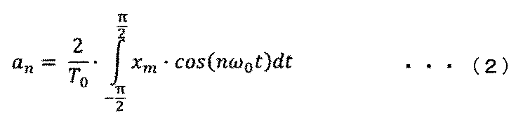
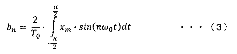
ここで、T0は基本波の周期(可動子6の往復運動する周期)、つまり1次周波数(駆動周波数)の逆数である。
可動子6を共振周波数で駆動させようと制御する場合、高次成分は重要ではなく、1次成分、つまり駆動周波数成分に注目すればよい。特に、可動子6の位置xmの1次周波数成分(駆動周波数成分)の位相が重要である。1次のフーリエ係数の逆正接により、正弦波状の印加電圧Vに対する可動子6の位置xmを次式(4)で求めることができる。

式(4)では、積分範囲を-2π~0としている。これは、位相差検出器130をマイコンやDSP(Digital Signal Processor)等の半導体集積回路等で実現する場合に、過去の情報しか取得できないためである。
図12は、位相差検出器の構成例及び駆動周波数と位相差検出器出力の関係の説明図であり、図12の上図は式(4)をブロック図で示した場合の説明図、図12の下図は駆動周波数と位相差検出器130の出力の関係の説明図である。位相指令値θ*を正弦演算器81(入力値の正弦を出力)と余弦演算器82(入力値の余弦を出力)それぞれに入力し、位相指令値θ*に対する正弦および余弦を得る。正弦および余弦それぞれを可動子6の位置xmと乗算した値が乗算器92から出力される。その出力をそれぞれ積分器94a,94bで積分すると、正弦および余弦それぞれの1次のフーリエ係数を得る。すなわち、フーリエ展開の駆動周波数ωより高次の周波数成分を消去できるので、高次のノイズに対してロバストに構成できる。
積分器94a,94bの出力を逆正接器86に入力する。逆正接器86は、入力された正弦および余弦成分を基に逆正接値を出力する。本実施例の逆正接器86は、分子を積分器94aの出力、分母を積分器94bの出力とした位相の逆正接値を出力するが、分子と分母を逆にした値を出力しても良い。図12の下図は、交流電圧の周波数(横軸)と、逆正接器86の出力値(位相差dltθ^)(縦軸)の関係を示す図である。図12の下図から分かるように、本実施例では、駆動周波数が共振周波数に一致する場合、90°が逆正接器86から出力される。逆正接器86から出力される値は、駆動周波数が共振周波数より高い場合は90°より大きく、駆動周波数が共振周波数より低い場合は、90°より小さい。これにより、基準位相θ*に対する位相差検出器130への入力交流信号(本実施例では、可動子6の位置xm)の1次周波数成分の位相差dltθ^を求めることができ、共振周波数の推定が可能になる。そして例えば、位相差dltθ^が90°超の場合は、位相差dltθ^が低下するように制御し、90°未満の場合は、増加するように制御すればよい。基準位相θ*と基本周波数θとが同値となるときの位相差dltθ^を目標値dltθ*として制御することが好ましい。
なお、積分器94a、94bに代えて、不完全積分器を用いることができる。不完全積分器はローパスフィルタの一種で、1次遅れフィルタと同様の構成にできる。その他、不完全積分器に代えて又は追加して、積分器94a,94b(又は不完全積分器)より前段に、ハイパスフィルタ(図示せず)を設けることができる。ハイパスフィルタの遮断周波数としては、例えば10又は5Hz以下にすることができる。
なお、積分器94a、94bに代えて、不完全積分器を用いることができる。不完全積分器はローパスフィルタの一種で、1次遅れフィルタと同様の構成にできる。その他、不完全積分器に代えて又は追加して、積分器94a,94b(又は不完全積分器)より前段に、ハイパスフィルタ(図示せず)を設けることができる。ハイパスフィルタの遮断周波数としては、例えば10又は5Hz以下にすることができる。
このように、位相差検出器130は、駆動周波数成分の1次のフーリエ係数の比の逆正接を用い、交流電圧指令値V*に対する可動子6の位置xmの位相θを求めるとき、位相差検出器130への入力交流信号の1次周波数成分のみに大きな感度を有する。つまり、例えば、可動子6の位置xmに、直流オフセットや高次のノイズが重畳された場合においても、基準位相θ*に対する位相差検出器130への入力交流信号の1次周波数成分の位相dltθをより正確に求められる。また、ハイパスフィルタを上記のように設ける場合は、さらに駆動周波数ωより小さな周波数に対してもロバストに構成できる。
したがって、可動子6の位置検出方法として、ノイズが重畳され易いシステム、例えばインダクタンスの可動子位置依存性が大きいシステムや、近傍に別の機器が存在するシステムを採用する場合に、特に有効な制御を実現できる。このように、高精度に共振周波数を検出あるいは推定し、高効率なリニアモータ駆動を実現することができる。
したがって、可動子6の位置検出方法として、ノイズが重畳され易いシステム、例えばインダクタンスの可動子位置依存性が大きいシステムや、近傍に別の機器が存在するシステムを採用する場合に、特に有効な制御を実現できる。このように、高精度に共振周波数を検出あるいは推定し、高効率なリニアモータ駆動を実現することができる。
<駆動周波数調整器131>
図13は、駆動周波数調整器131の構成例を説明する図である。周波数指令切替器155は、モード(1)とモード(2)とを切り替える指令であるモード切替信号(modeSW)に従って、2つの入力を切り替える。モード(1)ステップS162(図10)においては、周波数指令切替器155のA側に入力されている値を出力する。つまり、駆動周波数指令の初期値(ω0)がそのまま周波数指令値ω*として出力される。モード(2)ステップS163(図10)においては、周波数指令切替器155のB側に入力されている値を出力する。B側に入力されている値は次のように決定される。
図13は、駆動周波数調整器131の構成例を説明する図である。周波数指令切替器155は、モード(1)とモード(2)とを切り替える指令であるモード切替信号(modeSW)に従って、2つの入力を切り替える。モード(1)ステップS162(図10)においては、周波数指令切替器155のA側に入力されている値を出力する。つまり、駆動周波数指令の初期値(ω0)がそのまま周波数指令値ω*として出力される。モード(2)ステップS163(図10)においては、周波数指令切替器155のB側に入力されている値を出力する。B側に入力されている値は次のように決定される。
駆動周波数調整器131は、位相差指令値dltθ*(例えば、90°)と位相差検出器130で求めた位相差dltθ^の差を減算器91で求め、これに乗算器92bで比例ゲインKp_adtrを乗じて比例制御した演算結果と、乗算器92cで積分ゲインKi_adtrを乗じ、その結果を積分器94cで積分する積分制御した演算結果とを加算器90で加算し、駆動周波数指令値ω*を出力する。
なお、位相差指令値dltθ*は、上位の制御器(本実施例では示していない)から得ても良いし、本実施例のように予め例えば90°と設定しても良い。また、本実施例の駆動周波数調整器131は、比例積分制御の構成であるが、比例制御や積分制御など、他の制御構成も適用できる。
[高効率駆動の実現]
リニアモータ104を可動子6の質量とバネ定数から定まる機械的な共振周波数で駆動する場合の位相差検出器130と駆動周波数調整器131の動作を説明する。
例えば、可動子6の質量が設計値よりも重かった場合、実際の共振周波数は、設計値よりも低くなる。つまり、可動子6の質量設計値を用いて駆動周波数の初期値を決めた場合(設計値を利用して駆動周波数指令値ω*の初期値を決めた場合)には、実際の共振周波数よりも高い周波数で駆動することになる。この時、位相差検出器130で求めた位相差dltθ^は、位相差指令値dltθ*よりも大きい値となる。そのため、駆動周波数調整器131は、駆動周波数指令値ω*を減少させる制御を実行し、その結果、駆動周波数指令値ω*が実際の共振周波数に一致する。したがって、可動子6の速度エネルギーを有効活用でき、高効率にリニアモータ104を駆動することができる。
<電圧指令値作成器103>
図9を参照しつつ説明したように、電圧指令値作成器103には位相指令値θ*とストローク指令値l*が入力され、単相の交流電圧指令値Vm*が出力される。詳細について以下説明する。
ストローク指令切替器150は、図13に示したモード切替信号(modeSW)に従って、2つの入力を切り替える。ストローク指令値l*、位相指令値θ*、速度指令値vm*のいずれかを変更することにより、リニアモータ104に印加する電圧を調整することができる。つまり、印加電圧の振幅及び周波数を調整することで、駆動周波数を共振周波数に制御することやストロークを制御することが可能となる。
図9を参照しつつ説明したように、電圧指令値作成器103には位相指令値θ*とストローク指令値l*が入力され、単相の交流電圧指令値Vm*が出力される。詳細について以下説明する。
ストローク指令切替器150は、図13に示したモード切替信号(modeSW)に従って、2つの入力を切り替える。ストローク指令値l*、位相指令値θ*、速度指令値vm*のいずれかを変更することにより、リニアモータ104に印加する電圧を調整することができる。つまり、印加電圧の振幅及び周波数を調整することで、駆動周波数を共振周波数に制御することやストロークを制御することが可能となる。
モード(1)ステップS162(図10)においては、ストローク指令切替器150(図9等参照)のA側に入力されているストローク指令作成器151の出力値を出力する。
図14は、ストローク指令作成器151の構成を説明する図である。上位制御器(図示せず)等からリニアモータ104の起動指令(起動信号(MtrStart))が入力されると、起動信号切替器160の出力が起動指令に応じて0から1に変わる。起動信号切替器160の出力をストローク増加レート演算器161でストローク目標値Irefへの到達時間(T_inc)で除し、乗算器162でストローク目標値Irefと乗算し、乗じた値を積分器163で、積分する。これにより、傾きがIref/T_incの信号が得られる。次に、制限器164で、制限値入力(図14の例では、ストローク目標値Iref)の値に制限され、ストローク指令値l*_Aを得る。
モード(2)ステップ163(図10)においては、ストローク指令切替器150(図9)のB側に入力されているストローク制御器153の出力値を出力する。ストローク制御器153には、ストローク検出器152の出力等が入力される。
モード(2)ステップ163(図10)においては、ストローク指令切替器150(図9)のB側に入力されているストローク制御器153の出力値を出力する。ストローク制御器153には、ストローク検出器152の出力等が入力される。
図15は、ストローク検出器152の構成例を説明する図である。最大値検出器170および最小値検出器171は、所定の期間(例えば、基準位相θ*の[0,2π]期間)における、入力値(図15の例では、位置検出値xm)の最大値および最小値を出力する。両者を加算器172で加算した後、乗算器173で1/2を乗ずることにより、ストローク検出値lmを得る。
図16は、ストローク制御器153の構成例を説明する図である。ストローク制御器153は、ストローク目標値lrefとストローク検出器152で求めたストローク検出値lmの差を減算器175で求め、これに乗算器176で比例ゲインKp_stlを乗じて比例制御した演算結果と、乗算器177で積分ゲインKi_stlを乗じ、その結果を積分器178で積分する積分制御した演算結果とを加算器179で加算し、ストローク指令値l*_Bを出力する。
<PWM信号作成器133>
PWM信号作成器133には、三角波のキャリア信号と電圧指令値Vm*を比較することによる公知のパルス幅変調を用い、電圧指令値Vm*に応じたドライブ信号が生成される。
PWM信号作成器133には、三角波のキャリア信号と電圧指令値Vm*を比較することによる公知のパルス幅変調を用い、電圧指令値Vm*に応じたドライブ信号が生成される。
<電力変換回路105>
図17は、電力変換回路105を含む構成例を説明する図である。フルブリッジ回路126は、制御部102より入力されたドライブ信号に応じて直流電圧源120をスイッチングして、リニアモータ104に電圧を出力する。フルブリッジ回路126は4つのスイッチング素子122を備えており、直列接続されたスイッチング素子122a,122bを持つ第一上下アーム(以下、U相という。)と、スイッチング素子122c,122dを持つ第二上下アーム(以下、V相という。)と、を構成している。スイッチング素子122は、制御部102で生成される電圧指令値やパルス幅変調によるドライブ信号を基に、ゲートドライバ回路123が出力するパルス状のゲート信号(124a~124d)に応じてスイッチング動作できる。
スイッチング素子122の導通状態(オン/オフ)を制御することにより、直流電圧源120の直流電圧を交流電圧に相当する電圧を巻線8に出力できる。なお、直流電圧源120に代えて直流電流源を用いても良い。スイッチング素子122としては、例えば、IGBTやMOS-FETなどの半導体スイッチング素子を採用できる。
[リニアモータ104との結線]
電力変換回路105の第一上下アームのスイッチング素子122a,122b間および第二上下アームのスイッチング素子122c,122d間それぞれが、リニアモータ104に接続されている。図17では、上側および下側の電機子9の巻線8が並列に接続されている例を示しているが、巻線8を直列に接続することもできる。
電力変換回路105の第一上下アームのスイッチング素子122a,122b間および第二上下アームのスイッチング素子122c,122d間それぞれが、リニアモータ104に接続されている。図17では、上側および下側の電機子9の巻線8が並列に接続されている例を示しているが、巻線8を直列に接続することもできる。
[電流検出手段107]
U相下アームとV相下アームには、例えばCT(カレントトランス)等の電流検出器107を設けることができる。これにより、リニアモータ104の巻線に流れる電流Imを検出できる。
電流検出器107として、たとえば、CTに代えて、電力変換回路105の下アームにシャント抵抗125を付加し、シャント抵抗125に流れる電流からリニアモータ104に流れる電流を検出する相シャント電流方式を採用できる。電流検出手段107に代えて又は追加して、電力変換回路105の直流側に付加されたシャント抵抗125に流れる直流電流から、電力変換回路105の交流側の電流を検出するシングルシャント電流検出方式を採用しても良い。シングルシャント電流検出方式は、電力変換回路105を構成するスイッチング素子122の通電状態によって、シャント抵抗125に流れる電流が時間的に変化することを利用している。
なお、モード遷移電圧指令値Vm*1は、電力変換回路の直流電圧源120にある比率を乗じて求めた値や、リニアモータ104の誘起電圧と電力変換回路の直流電圧源120の比率、または、可動子6の最大ストローク長に対する可動子6の位置xmの比率などによっても決定することができる。
以上のように、本実施例によれば、交流電圧の周波数を略一定に保ち振幅を単調増加させる運転モード(1)と、可動子の交流電圧と可動子位置の位相差を求め、可動子のストロークを一定に保ちつつ、その位相差が所定値となるように、交流電圧の周波数を変化させる運転モード(2)を備えることにより、起動時の負荷によらず可動子6のストロークを所望のストロークに制御し、安定な起動を実現できる。
本実施例は、可動子等の質量の偏差等に対応した効果を奏し得るため、負荷が変動しない場合でも有効である。
本実施例は、可動子等の質量の偏差等に対応した効果を奏し得るため、負荷が変動しない場合でも有効である。
本実施例の構成は、下記の点を除き実施例1と同様にできる。本実施例は、モータ電流Imを利用して共振周波数を推定すると共に、印加電圧Vmやモータ電流Im等を利用して相対位置を推定する。
<リニアモータ駆動装置201>
図18は、本発明の他の実施例に係る実施例2のリニアモータシステム200の全体概略構成図である。リニアモータシステム200は、リニアモータ駆動装置201と、リニアモータ104から構成される。
図18は、本発明の他の実施例に係る実施例2のリニアモータシステム200の全体概略構成図である。リニアモータシステム200は、リニアモータ駆動装置201と、リニアモータ104から構成される。
リニアモータ駆動装置201は、少なくとも位置推定部208と位相差検出器230を有する制御部202と、電流検出器207と、電力変換回路105を有する。
<位相差検出器230>
図19は、本実施例の位相差検出器230の構成例を示す説明図である。位相指令値θ*(基準位相θ*)を正弦演算器81(入力値の正弦を出力)と余弦演算器82(入力値の余弦を出力)それぞれに入力し、位相指令値θ*(基準位相θ*)に対する正弦および余弦を得る。正弦および余弦それぞれをモータ電流Imと乗算した値が乗算器92から出力される。その出力をそれぞれ、遅れフィルタの一例である一次遅れフィルタ141a,141bで演算すると、正弦および余弦それぞれの1次のフーリエ係数を得る。すなわち、フーリエ展開の駆動周波数ωより高次の周波数成分を消去できるので、高次のノイズに対してロバストに構成できる。
一次遅れフィルタ141a,141bの出力を逆正接器86に入力する。逆正接器86は、入力された正弦および余弦成分を基に逆正接値を出力する。本実施例の逆正接器86は、分子を一次遅れフィルタ141aの出力の負値、分母を一次遅れフィルタ141bの出力とした位相の逆正接値を出力する。もちろん、実施例1で説明したように、分子と分母を逆にした値を出力しても良い。
図20は、交流電圧の駆動周波数(横軸)と、逆正接器86の出力値(位相差dltθ)(縦軸)の関係を示す図である。本実施例では、駆動周波数が共振周波数である場合、0°が逆正接器86から出力される。逆正接器86から出力される値は、駆動周波数が共振周波数より高い場合は0°より大きく、駆動周波数が共振周波数より低い場合は、0°より小さい。これにより、基準位相θ*に対する位相差検出器230への入力交流信号(本実施例では、可動子6の位置xm)の1次周波数成分の位相差dltθを求めることができ、共振周波数の推定が可能になる。
<位置推定手段208>
位置推定部208は、可動子6の位置を推定する。例えばリニアモータ104に印加する電圧Vmと、リニアモータ104に流れる電流Imを利用して、例えば次式(5)で位置推定値xm^を求める。
位置推定部208は、可動子6の位置を推定する。例えばリニアモータ104に印加する電圧Vmと、リニアモータ104に流れる電流Imを利用して、例えば次式(5)で位置推定値xm^を求める。

式中、Vm*はリニアモータ104に印加する電圧指令値Vm*である。
図21は、位置推定部208の構成例を示す説明図であり、式(5)をブロック図で示した場合の説明図である。なお、位置推定部208には、上記以外にも公知の同期式モータの位置推定方法を適用することができる。位置推定値xm^を図15のストローク検出器152に入力すれば、所望のストロークに制御することができる。
このように、本実施例によれば、リニアモータ104に印加する電圧と、リニアモータ104に流れる電流から可動子6の位置を推定し、位置推定値を基に、高精度に共振周波数を検出あるいは推定することで高効率なリニアモータ駆動を提供することができる。さらに、交流電圧の周波数を一定に保ち振幅を単調増加させる運転モード(1)と、可動子の交流電圧と可動子位置の位相差を求め、可動子のストロークを一定に保ちつつ、その位相差が所定値となるように、交流電圧の周波数を変化させる運転モード(2)を備えることにより、起動時の負荷によらず可動子の6のストロークを所望のストロークに制御し、安定な起動を実現できるリニアモータ駆動を実現することができる。
本実施例の構成は、下記の点を除き実施例1又は2と同様にできる。本実施例は、リニアモータシステム100を搭載した機器の一例としての密閉型圧縮機50に関する。機器としては、往復運動する振動体(可動子6)に対して、その位相θや駆動周波数ωに応じて変動する負荷を与えるもの等を用いることができる。
<密閉型圧縮機50>
図22は、本発明の他の実施例に係る実施例3の密閉型圧縮機の縦断面図であり、リニアモータ104を有する密閉型圧縮機50の縦断面図の一例である。密閉型圧縮機50は、圧縮要素20と電動要素30とが密閉容器3内に配置されたレシプロ圧縮機である。圧縮要素20及び電動要素30は支持バネ49によって密閉容器3内に弾性的に支持されている。電動要素30は、可動子6及び電機子9を含む。
図22は、本発明の他の実施例に係る実施例3の密閉型圧縮機の縦断面図であり、リニアモータ104を有する密閉型圧縮機50の縦断面図の一例である。密閉型圧縮機50は、圧縮要素20と電動要素30とが密閉容器3内に配置されたレシプロ圧縮機である。圧縮要素20及び電動要素30は支持バネ49によって密閉容器3内に弾性的に支持されている。電動要素30は、可動子6及び電機子9を含む。
圧縮要素20はシリンダ1aを形成するシリンダブロック1と、シリンダブロック1の端面に組み立てられるシリンダヘッド16と、吐出室空間を形成するヘッドカバー17とを備えている。シリンダ1a内に供給された作動流体はピストン4の往復動によって圧縮され、圧縮された作動流体は圧縮機外部に連通する吐出管(図示せず)へと送られる。
可動子6の一端にはピストン4が取り付けられている。本実施例では、可動子6及びピストン4が往復運動することで、作動流体を圧縮及び膨張させる。この圧縮及び膨張に要する仕事等が変動する負荷に相当する。電動要素30の片端には圧縮要素20を配置してある。シリンダブロック1は、可動子6の往復動を案内するガイドロッドを前後方向に沿って有している。
可動子6の一端にはピストン4が取り付けられている。本実施例では、可動子6及びピストン4が往復運動することで、作動流体を圧縮及び膨張させる。この圧縮及び膨張に要する仕事等が変動する負荷に相当する。電動要素30の片端には圧縮要素20を配置してある。シリンダブロック1は、可動子6の往復動を案内するガイドロッドを前後方向に沿って有している。
密閉容器3にリニアモータ104を設置する場合は、ハーメチックコネクタやハーメチックシールと呼ばれる、気密性を持ったコネクタが用いられることがある。気密性を保つためには、コネクタの数は最小限にするのが望ましい。そのため、本実施例のリニアモータシステム300(図23)は、リニアモータ104に印加する電圧Vmと、リニアモータ104に流れるモータ電流Imから可動子6の位置を推定し、位置推定値xm^を基に、高精度に共振周波数を検出あるいは推定し、高効率なリニアモータ駆動を提供する。
可動子6に弾性体である共振バネ23(図22中では図示せず)を付加し、可動子6の質量とバネ定数から定まる機械的な共振周波数で可動子6を往復運動させる場合、圧縮要素20による共振周波数への影響も考慮する必要がある。すなわち、吐出空間の圧力によって、作動流体のバネ的な作用が加わるため、共振状態となる周波数が変化する。つまり、シリンダ1a内の圧力が高い場合には、可動子6に付加された共振バネ23のバネ定数が高いのと等価であり、共振周波数は高くなる。反対に、シリンダ1a内の圧力が低い場合には、可動子6に付加された共振バネ23のバネ定数が支配的となり、共振周波数は、可動子6の質量とバネ定数から定まる機械的な共振周波数に近い。
また、シリンダ1a内の圧力を考慮せずに共振周波数を推定すると、想定以上に可動子6のストロークが大きくなり、ピストン4がシリンダヘッド16に衝突する恐れがある。ピストン4がシリンダヘッド16に衝突すると、騒音となるだけでなく、最悪の場合、ピストン4やシリンダヘッド16が破損し得る。そのため、起動時等の過渡時においても適切にストロークを制御することが望ましい。
また、シリンダ1a内の圧力を考慮せずに共振周波数を推定すると、想定以上に可動子6のストロークが大きくなり、ピストン4がシリンダヘッド16に衝突する恐れがある。ピストン4がシリンダヘッド16に衝突すると、騒音となるだけでなく、最悪の場合、ピストン4やシリンダヘッド16が破損し得る。そのため、起動時等の過渡時においても適切にストロークを制御することが望ましい。
このように、リニアモータ104を圧縮要素20の動力とする場合は、圧縮要素20の条件によって共振周波数が変化してしまう。このような場合においても所望のストロークを得るためには、条件によって変化する共振周波数を高精度に検出あるいは推定することが必要である。そのため、図23に示すように、本実施例のリニアモータシステム300は、リニアモータ104に印加する電圧と、リニアモータ104に流れる電流から可動子6の位置を推定し、位置推定値を基に、高精度に共振周波数を検出あるいは推定し、高効率なリニアモータ駆動を実現できる。印加電圧Vmやモータ電流Imに基づいて可動子6の位置を推定できるため、高温高圧環境となる密閉容器3内に位置センサを配する必要性を低減できる。また、リニアモータ104の負荷(例えば、圧力要素20の吸込圧力と吐出圧力の差に比例する)に応じて、制御ゲインを適切に切り替えることにより、無負荷(圧力要素20の吸込圧力と吐出圧力が均圧状態)から重負荷といった、幅広い負荷条件においても安定に起動および駆動できるリニアモータ駆動を実現できる。
<リニアモータ駆動装置301による起動制御等>
図23は、本実施例のリニアモータシステム300の全体概略構成図である。リニアモータシステム300は、リニアモータ駆動装置301と、リニアモータ104から構成される。
リニアモータ駆動装置301は、少なくとも位置推定部308と位相差検出器330を有する制御部302と、電流検出器307と、電力変換回路105を有する。
図23は、本実施例のリニアモータシステム300の全体概略構成図である。リニアモータシステム300は、リニアモータ駆動装置301と、リニアモータ104から構成される。
リニアモータ駆動装置301は、少なくとも位置推定部308と位相差検出器330を有する制御部302と、電流検出器307と、電力変換回路105を有する。
図24は、各起動シーケンスにおける主要な指令値の時間変化を説明する図である。図24には、図11に比べ、ゲイン切替信号(gainSW)が追加されている。ゲイン切替信号(gainSW)は、その状態(HまたはL)に応じて、各制御器(例えば、図25に示すストローク制御器353)の制御ゲインを切り替える。状態Hの制御ゲインは、状態Lの制御ゲインより大きい。
状態H,Lの設定としては、例えば、重負荷時を状態Hに、無負荷又は軽負荷時を状態Lにできる。負荷の軽重は、作動流体の膨張を軽負荷、作動流体の圧縮を重負荷とする短時間の変動に注目した設定でも良いし、流量が比較的少ない時間帯を軽負荷、比較的多い時間帯を重負荷とする長時間の変動に注目した設定でも良い。
なお、軽負荷、重負荷の判定(負荷の軽重の判定)は、密閉型圧縮機50が無負荷のときの共振周波数の情報を予め得ておき、これと比較することで可能である。具体的には、負荷が大きいと共振周波数が減少していくため、どの程度無負荷時の共振周波数と異なる値で共振するかを検討することで、負荷の軽重を推定できる。
なお、軽負荷、重負荷の判定(負荷の軽重の判定)は、密閉型圧縮機50が無負荷のときの共振周波数の情報を予め得ておき、これと比較することで可能である。具体的には、負荷が大きいと共振周波数が減少していくため、どの程度無負荷時の共振周波数と異なる値で共振するかを検討することで、負荷の軽重を推定できる。
密閉型圧縮機50を駆動する場合、起動時は、短時間で共振周波数に制御されることが望ましい。制御器の応答時間を短くするためには、制御ゲイン(例えば、図25に示す比例ゲインKp_stl)を大きくすれば良い。しかし、必要以上に制御ゲインを大きくすると、定常状態(指令値との差が小さい状態)では、振動的になるという課題がある。
図25は、本実施例のストローク制御器353の構成を説明する図である。ゲイン切替器360は、ゲイン切替信号(gainSW)の状態(HまたはL)に応じて、乗算器376および乗算器377の制御ゲイン(比例ゲインKp_stlおよび積分ゲインKi_stl)を切り替える。
本実施例では、起動直後を状態Hとしており、電圧の振幅の変化速度(時間微分値)を大きくしているため、高速でモード(1)を実行してモード(2)に遷移しやすい。そして、モード(2)実行中の時間T2でゲイン切替信号がHからLに切り替わるものとする。時間T2までの起動初期においては、圧縮要素20の条件によっては、駆動周波数と共振周波数の乖離が大きい。このような状態で、短時間で高精度に共振周波数を検出あるいは推定することで高効率なリニアモータ駆動を実現すると共に、起動時の負荷によらず可動子6のストロークを所望のストロークに制御し、安定な起動を実現するために、制御ゲインを大きくしている。
一方、駆動周波数が共振周波数と略一致したならば、この時間をT2として制御ゲインを小さくする。駆動周波数と共振周波数とが略一致した状態では、電動要素30の電気時定数に対し、圧縮要素20の機械時定数のほうが長い。つまり、圧縮要素20の条件による共振周波数の変化は、各制御器の応答時間よりも十分長い。そのため、制御ゲインを小さくする。
図24の時間T4は、上位制御器(図示せず)などから、圧縮要素20の必要流量(ストロークと駆動周波数の積で求められる)が変更になり(少なく)、ストローク指令値l*が減少された瞬間である。この場合、ストローク検出値lmが、ストローク指令値(ls*_2)に達した後、圧縮要素20による共振周波数への影響が出始め、共振周波数が低下している。この場合、必要以上に、駆動周波数調整器131により駆動周波数を上げると、駆動周波数が安定しない恐れがある。そのため、同様に、駆動周波数調整器131にもゲイン切替器360(図25等参照)を構成し、ゲイン切替信号(gainSW)の状態(HまたはL)に応じて、上述の図13に示した、駆動周波数調整器131を構成する、乗算器92bおよび乗算器92cの制御ゲイン(比例ゲインKp_adtrおよび積分ゲインKi_adtr)を切り替える。
このように、本実施例によれば、リニアモータ104に印加する電圧と、リニアモータ104に流れる電流から可動子6の位置を推定し、位置推定値を基に、高精度に共振周波数を検出あるいは推定することで高効率なリニアモータ駆動を実現することができる。さらに、交流電圧の周波数を一定に保ち振幅を単調増加させる運転モード(1)と、可動子の交流電圧と可動子位置の位相差を求め、可動子のストロークを一定に保ちつつ、その位相差が所定値となるように、交流電圧の周波数を変化させる運転モード(2)を備えることにより、起動時の負荷によらず可動子6のストロークを所望のストロークに制御し、安定な起動を実現できるリニアモータ駆動を提供することができる。また、リニアモータ104の負荷(例えば、圧力要素20の吸込圧力と吐出圧力の差に比例する)に応じて、制御ゲインを適切に切り替えることにより、無負荷(圧力要素20の吸込圧力と吐出圧力が均圧状態)から重負荷といった、幅広い負荷条件においても安定に起動および駆動できるリニアモータ駆動を実現することができる。
なお、本実施例に示した圧縮機は、凝縮器又は蒸発器として機能する熱交換器を備える空気調和器において、冷媒を圧送するための圧縮機に適用できる。また、圧縮機の駆動を制御するリニアモータ駆動装置として、上述の実施例1又は実施例2に示したリニアモータ駆動装置を採用することができる。
また、本実施例に示した圧縮機は、エアサスペンションにおいて車高を調整するために作動流体を圧縮する圧縮機に適用できる。また、圧縮機の駆動を制御するリニアモータ駆動装置として、上述の実施例1又は実施例2に示したリニアモータ駆動装置を採用することができる。
更にまた、本実施例に示した圧縮機は、凝縮器及び蒸発器を有する冷蔵庫において、液冷媒を圧送する圧縮機にも適用可能である。また、圧縮機の駆動を制御するリニアモータ駆動装置として、上述の実施例1又は実施例2に示したリニアモータ駆動装置を採用することができる。
また、本実施例に示した圧縮機は、エアサスペンションにおいて車高を調整するために作動流体を圧縮する圧縮機に適用できる。また、圧縮機の駆動を制御するリニアモータ駆動装置として、上述の実施例1又は実施例2に示したリニアモータ駆動装置を採用することができる。
更にまた、本実施例に示した圧縮機は、凝縮器及び蒸発器を有する冷蔵庫において、液冷媒を圧送する圧縮機にも適用可能である。また、圧縮機の駆動を制御するリニアモータ駆動装置として、上述の実施例1又は実施例2に示したリニアモータ駆動装置を採用することができる。
本発明は上記した実施例に限定されるものではなく、様々な変形例が含まれる。例えば、上記した実施例は本発明を分かりやすく説明するために詳細に説明したものであり、必ずしも説明した全ての構成を備えるものに限定されるものではない。
また、上記の各構成、機能、処理部、処理手続き等は、それらの一部または全部を、例えば集積回路で設計する等によりハードウェアで実現しても良い。また、上記の各構成や機能等は、プロセッサがそれぞれの機能を実現するプログラムを解釈し、実行することによりソフトウェアで実現しても良い。
また、上記の各構成、機能、処理部、処理手続き等は、それらの一部または全部を、例えば集積回路で設計する等によりハードウェアで実現しても良い。また、上記の各構成や機能等は、プロセッサがそれぞれの機能を実現するプログラムを解釈し、実行することによりソフトウェアで実現しても良い。
1…シリンダブロック,1a…シリンダ,2…永久磁石,3…密閉容器,4…ピストン,6…可動子,7…磁極,8…巻線,9…電機子,16…シリンダヘッド,17…ヘッドカバー,20…圧縮要素,23…共振バネ(アシストバネ),30…電動要素,50…密閉型圧縮機,100,200,300…リニアモータシステム,101,201,301…リニアモータ駆動装置,102,202,302…制御部,103…電圧指令値作成器,104…リニアモータ,105…電力変換回路,107…電流検出器,122…スイッチング素子,126…フルブリッジ回路,130,230,330…位相差検出器,131…駆動周波数調整器,133…PWM信号作成器
Claims (18)
- 交流電圧が印加される巻線と、
弾性体が接続する可動子と、を備えるリニアモータ制御装置であって、
前記交流電圧の周波数を略一定に保ちつつ前記交流電圧の振幅を単調増加させる運転モード(1)と、
前記交流電圧の振幅を略一定に保ちつつ、前記交流電圧の周波数を変化させる運転モード(2)と、を有し、
前記運転モード(1)、前記運転モード(2)の順で実行することを特徴とするリニアモータ制御装置。 - 前記運転モード(1)を、リニアモータの起動直後に実行し、
前記運転モード(1)で前記可動子の振幅を所定以上に大きくした後に、前記可動子の位置推定及び/又は前記可動子の共振周波数の推定を行うことを特徴とする請求項1に記載のリニアモータ制御装置。 - 前記運転モード(2)では、前記交流電圧の振幅を略一定に保ちつつ、周波数を変化させる制御を実行し、その後、前記交流電圧の振幅を増加させる制御を実行することを特徴とする請求項2に記載のリニアモータ制御装置。
- 前記可動子に接続した負荷を有し、
前記交流電圧の周波数と、検出又は推定した前記可動子の共振周波数と、の差から前記負荷が変動したことを推定し、
前記交流電圧の振幅、前記交流電圧の周波数、又は前記可動子の振幅のうち、1つ、2つ又は3つの時間微分値は、前記負荷が軽負荷の場合より重負荷の場合の方が大きいことを特徴とする請求項1に記載のリニアモータ制御装置。 - 前記可動子に接続した負荷を有し、
前記交流電圧の周波数と、検出又は推定した前記可動子の共振周波数と、の差から前記負荷が変動したことを推定し、
前記交流電圧の振幅、前記交流電圧の周波数、又は前記可動子の振幅のうち、1つ、2つ又は3つの時間微分値は、前記負荷が軽負荷の場合より重負荷の場合の方が大きいことを特徴とする請求項2に記載のリニアモータ制御装置。 - 前記可動子に接続した負荷を有し、
前記交流電圧の周波数と、検出又は推定した前記可動子の共振周波数と、の差から前記負荷が変動したことを推定し、
前記交流電圧の振幅、前記交流電圧の周波数、又は前記可動子の振幅のうち、1つ、2つ又は3つの時間微分値は、前記負荷が軽負荷の場合より重負荷の場合の方が大きいことを特徴とする請求項3に記載のリニアモータ制御装置。 - 前記可動子に接続した負荷を有し、
前記交流電圧の周波数と、検出又は推定した前記可動子の共振周波数と、の差から前記負荷が変動したことを推定し、
前記負荷に応じて、前記可動子のストローク、前記巻線に流れる電流、又は前記可動子の速度に対する制御ゲイン又は制御時定数を変化させることを特徴とする請求項1に記載のリニアモータ制御装置。 - 前記可動子に接続した負荷を有し、
前記交流電圧の周波数と、検出又は推定した前記可動子の共振周波数と、の差から前記負荷が変動したことを推定し、
前記負荷に応じて、前記可動子のストローク、前記巻線に流れる電流、又は前記可動子の速度に対する制御ゲイン又は制御時定数を変化させることを特徴とする請求項2に記載のリニアモータ制御装置。 - 前記可動子に接続した負荷を有し、
前記交流電圧の周波数と、検出又は推定した前記可動子の共振周波数と、の差から前記負荷が変動したことを推定し、
前記負荷に応じて、前記可動子のストローク、前記巻線に流れる電流、又は前記可動子の速度に対する制御ゲイン又は制御時定数を変化させることを特徴とする請求項3に記載のリニアモータ制御装置。 - 請求項1に記載のリニアモータ制御装置を有する圧縮機であって、
前記可動子の位置を、前記巻線の電圧及び電流値を利用して推定することを特徴とする圧縮機。 - 請求項2に記載のリニアモータ制御装置を有する圧縮機であって、
前記可動子の位置を、前記巻線の電圧及び電流値を利用して推定することを特徴とする圧縮機。 - 請求項3に記載のリニアモータ制御装置を有する圧縮機であって、
前記可動子の位置を、前記巻線の電圧及び電流値を利用して推定することを特徴とする圧縮機。 - 請求項4に記載のリニアモータ制御装置を有する圧縮機であって、
前記可動子の位置を、前記巻線の電圧及び電流値を利用して推定することを特徴とする圧縮機。 - 請求項5に記載のリニアモータ制御装置を有する圧縮機であって、
前記可動子の位置を、前記巻線の電圧及び電流値を利用して推定することを特徴とする圧縮機。 - 請求項6に記載のリニアモータ制御装置を有する圧縮機であって、
前記可動子の位置を、前記巻線の電圧及び電流値を利用して推定することを特徴とする圧縮機。 - 請求項7に記載のリニアモータ制御装置を有する圧縮機であって、
前記可動子の位置を、前記巻線の電圧及び電流値を利用して推定することを特徴とする圧縮機。 - 請求項8に記載のリニアモータ制御装置を有する圧縮機であって、
前記可動子の位置を、前記巻線の電圧及び電流値を利用して推定することを特徴とする圧縮機。 - 請求項9に記載のリニアモータ制御装置を有する圧縮機であって、
前記可動子の位置を、前記巻線の電圧及び電流値を利用して推定することを特徴とする圧縮機。
Priority Applications (3)
| Application Number | Priority Date | Filing Date | Title |
|---|---|---|---|
| DE112017004451.0T DE112017004451T5 (de) | 2016-10-13 | 2017-10-05 | Linearmotorsteuervorrichtung und damit ausgestatteter Verdichter |
| CN201780061850.4A CN109792224B (zh) | 2016-10-13 | 2017-10-05 | 线性马达控制装置以及搭载有线性马达控制装置的压缩机 |
| US16/341,177 US11329541B2 (en) | 2016-10-13 | 2017-10-05 | Linear motor control apparatus and compressor equipped with the same |
Applications Claiming Priority (2)
| Application Number | Priority Date | Filing Date | Title |
|---|---|---|---|
| JP2016-201511 | 2016-10-13 | ||
| JP2016201511A JP6749205B2 (ja) | 2016-10-13 | 2016-10-13 | リニアモータ制御装置及びこれを搭載した圧縮機 |
Publications (1)
| Publication Number | Publication Date |
|---|---|
| WO2018070339A1 true WO2018070339A1 (ja) | 2018-04-19 |
Family
ID=61905633
Family Applications (1)
| Application Number | Title | Priority Date | Filing Date |
|---|---|---|---|
| PCT/JP2017/036319 Ceased WO2018070339A1 (ja) | 2016-10-13 | 2017-10-05 | リニアモータ制御装置及びこれを搭載した圧縮機 |
Country Status (5)
| Country | Link |
|---|---|
| US (1) | US11329541B2 (ja) |
| JP (1) | JP6749205B2 (ja) |
| CN (1) | CN109792224B (ja) |
| DE (1) | DE112017004451T5 (ja) |
| WO (1) | WO2018070339A1 (ja) |
Families Citing this family (8)
| Publication number | Priority date | Publication date | Assignee | Title |
|---|---|---|---|---|
| KR20200068436A (ko) | 2018-12-05 | 2020-06-15 | 엘지전자 주식회사 | 리니어 압축기 및 리니어 압축기의 제어 방법 |
| CN111555690B (zh) * | 2019-12-27 | 2022-04-05 | 瑞声科技(新加坡)有限公司 | 马达振动位移的控制方法、存储介质及电子设备 |
| US12101044B2 (en) * | 2020-05-13 | 2024-09-24 | Mitsubishi Electric Corporation | Linear motor system |
| JP7258242B2 (ja) * | 2020-08-19 | 2023-04-14 | 三菱電機株式会社 | 電源変調装置、電源変調方法及びドハティ増幅器 |
| CN112012915B (zh) * | 2020-08-31 | 2022-04-29 | 扬州大学 | 一种活塞式线性压缩机行程控制装置及其控制方法 |
| CN114509156B (zh) * | 2020-11-16 | 2023-10-20 | 深圳市万普拉斯科技有限公司 | 一种线性马达的校准方法、电子装置及存储介质 |
| CN117678155A (zh) * | 2021-09-03 | 2024-03-08 | 发那科株式会社 | 频率特性预测装置及频率特性预测方法 |
| WO2026095112A1 (ko) * | 2024-10-30 | 2026-05-07 | 엘지전자 주식회사 | 리니어 압축기의 제어 장치 |
Citations (3)
| Publication number | Priority date | Publication date | Assignee | Title |
|---|---|---|---|---|
| JP2004218461A (ja) * | 2003-01-10 | 2004-08-05 | Fuji Electric Systems Co Ltd | 振動型圧縮機 |
| JP2005054768A (ja) * | 2003-08-04 | 2005-03-03 | Samsung Electronics Co Ltd | リニア圧縮機及びその制御装置 |
| JP2015231284A (ja) * | 2014-06-04 | 2015-12-21 | ミネベア株式会社 | 振動発生器の制御方法および振動発生器 |
Family Cites Families (20)
| Publication number | Priority date | Publication date | Assignee | Title |
|---|---|---|---|---|
| GB8805420D0 (en) * | 1988-03-08 | 1988-04-07 | Framo Dev Ltd | Electrically powered pump unit |
| GB9119448D0 (en) * | 1991-09-12 | 1991-10-23 | Vickers Systems Ltd | System controls |
| US5980211A (en) * | 1996-04-22 | 1999-11-09 | Sanyo Electric Co., Ltd. | Circuit arrangement for driving a reciprocating piston in a cylinder of a linear compressor for generating compressed gas with a linear motor |
| KR100504319B1 (ko) * | 1996-07-09 | 2005-09-26 | 산요덴키가부시키가이샤 | 선형압축기 |
| JP3674216B2 (ja) * | 1997-02-25 | 2005-07-20 | 松下電工株式会社 | リニア振動モータの駆動制御方法 |
| TW353707B (en) * | 1997-09-26 | 1999-03-01 | Nat Science Council | Control device for linear compressor |
| JPH11351143A (ja) | 1998-06-10 | 1999-12-21 | Matsushita Electric Ind Co Ltd | リニアコンプレッサーの駆動装置 |
| FR2801645B1 (fr) * | 1999-11-30 | 2005-09-23 | Matsushita Electric Industrial Co Ltd | Dispositif d'entrainement d'un compresseur lineaire, support et ensemble d'informations |
| JP3511018B2 (ja) * | 2001-05-18 | 2004-03-29 | 松下電器産業株式会社 | リニアコンプレッサ駆動装置 |
| JP2003339188A (ja) * | 2002-05-21 | 2003-11-28 | Matsushita Electric Ind Co Ltd | リニアモータの駆動装置 |
| JP3540311B2 (ja) * | 2002-05-31 | 2004-07-07 | 松下電器産業株式会社 | モータ駆動制御装置 |
| EP1509994B1 (en) * | 2002-07-16 | 2006-08-30 | Matsushita Electric Industrial Co., Ltd. | Control system for a linear vibration motor |
| US20040123195A1 (en) * | 2002-12-20 | 2004-06-24 | Rohrbaugh John G. | Systems and methods for testing tri-state bus drivers |
| CN1780138A (zh) * | 2004-11-18 | 2006-05-31 | 乐金电子(天津)电器有限公司 | 线性压缩机的驱动装置及其驱动方法 |
| US7408310B2 (en) * | 2005-04-08 | 2008-08-05 | Lg Electronics Inc. | Apparatus for controlling driving of reciprocating compressor and method thereof |
| KR100739165B1 (ko) * | 2006-04-13 | 2007-07-13 | 엘지전자 주식회사 | 리니어 압축기의 운전제어장치 및 방법 |
| KR101415058B1 (ko) * | 2007-12-11 | 2014-07-04 | 엘지전자 주식회사 | 인버터 리니어 압축기 제어 장치 및 방법 |
| KR101838633B1 (ko) * | 2011-07-22 | 2018-03-14 | 엘지전자 주식회사 | 이동 단말기 및 그의 진동력 제어방법 |
| US11466678B2 (en) * | 2013-11-07 | 2022-10-11 | Gas Technology Institute | Free piston linear motor compressor and associated systems of operation |
| JP6667220B2 (ja) * | 2015-07-14 | 2020-03-18 | キヤノン株式会社 | 振動型アクチュエータの制御装置とその制御方法、駆動装置、撮像装置、及び自動ステージ |
-
2016
- 2016-10-13 JP JP2016201511A patent/JP6749205B2/ja active Active
-
2017
- 2017-10-05 DE DE112017004451.0T patent/DE112017004451T5/de active Pending
- 2017-10-05 CN CN201780061850.4A patent/CN109792224B/zh active Active
- 2017-10-05 WO PCT/JP2017/036319 patent/WO2018070339A1/ja not_active Ceased
- 2017-10-05 US US16/341,177 patent/US11329541B2/en active Active
Patent Citations (3)
| Publication number | Priority date | Publication date | Assignee | Title |
|---|---|---|---|---|
| JP2004218461A (ja) * | 2003-01-10 | 2004-08-05 | Fuji Electric Systems Co Ltd | 振動型圧縮機 |
| JP2005054768A (ja) * | 2003-08-04 | 2005-03-03 | Samsung Electronics Co Ltd | リニア圧縮機及びその制御装置 |
| JP2015231284A (ja) * | 2014-06-04 | 2015-12-21 | ミネベア株式会社 | 振動発生器の制御方法および振動発生器 |
Also Published As
| Publication number | Publication date |
|---|---|
| DE112017004451T5 (de) | 2019-07-11 |
| US20200195119A1 (en) | 2020-06-18 |
| JP2018064379A (ja) | 2018-04-19 |
| CN109792224A (zh) | 2019-05-21 |
| US11329541B2 (en) | 2022-05-10 |
| JP6749205B2 (ja) | 2020-09-02 |
| CN109792224B (zh) | 2022-09-27 |
Similar Documents
| Publication | Publication Date | Title |
|---|---|---|
| JP6749205B2 (ja) | リニアモータ制御装置及びこれを搭載した圧縮機 | |
| CN101390277B (zh) | 预测控制的直线型驱动器或直线型压缩机及预测控制方法 | |
| JP3554269B2 (ja) | リニアモータ駆動装置、媒体、および情報集合体 | |
| KR20030091716A (ko) | 리니어 모터의 구동장치 | |
| WO2002095923A1 (en) | Linear compressor drive device | |
| JP6899720B2 (ja) | リニアモータシステム及びそれを有する圧縮機 | |
| EP1724914A2 (en) | System and method for controlling linear compressor | |
| WO2017006744A1 (ja) | モータシステム及びこれを備える機器 | |
| JP2003199388A (ja) | モータ駆動装置 | |
| US11401924B2 (en) | Linear compressor and linear compressor control system | |
| Suzuki et al. | Position sensor-less resonant frequency estimation method for linear compressor with assist springs | |
| JP6965048B2 (ja) | リニアモータシステム | |
| JP6591668B2 (ja) | リニアモータシステム及び圧縮機 | |
| JP6916053B2 (ja) | リニアモータシステム | |
| WO2019154092A1 (zh) | 一种用于线性压缩机的行程估算方法和装置 | |
| JP2019193408A (ja) | 振動抑制装置及びリニアモータ制御装置 | |
| Suzuki et al. | Resonant frequency tracking control for a linear compressor with assist springs | |
| JP2009017755A (ja) | リニアモータ制御装置およびスターリング機関 | |
| Benecke et al. | Design and control of a linear reluctance motor for a vacuum diaphragm pump | |
| KR101403007B1 (ko) | 리니어 압축기 및 그 제어 방법 | |
| CN121569110A (zh) | 家用电器的线性压缩机的运行 | |
| Xue et al. | A controller for linear compressors propelled by linear switched reluctance actuators | |
| WO2014125771A1 (ja) | リニアアクチュエーター |
Legal Events
| Date | Code | Title | Description |
|---|---|---|---|
| 121 | Ep: the epo has been informed by wipo that ep was designated in this application |
Ref document number: 17859486 Country of ref document: EP Kind code of ref document: A1 |
|
| 122 | Ep: pct application non-entry in european phase |
Ref document number: 17859486 Country of ref document: EP Kind code of ref document: A1 |