WO2018066719A1 - 画像形成装置 - Google Patents
画像形成装置 Download PDFInfo
- Publication number
- WO2018066719A1 WO2018066719A1 PCT/JP2017/037094 JP2017037094W WO2018066719A1 WO 2018066719 A1 WO2018066719 A1 WO 2018066719A1 JP 2017037094 W JP2017037094 W JP 2017037094W WO 2018066719 A1 WO2018066719 A1 WO 2018066719A1
- Authority
- WO
- WIPO (PCT)
- Prior art keywords
- image
- toner
- developer
- amount
- ratio
- Prior art date
- Legal status (The legal status is an assumption and is not a legal conclusion. Google has not performed a legal analysis and makes no representation as to the accuracy of the status listed.)
- Ceased
Links
Images



Classifications
-
- G—PHYSICS
- G03—PHOTOGRAPHY; CINEMATOGRAPHY; ANALOGOUS TECHNIQUES USING WAVES OTHER THAN OPTICAL WAVES; ELECTROGRAPHY; HOLOGRAPHY
- G03G—ELECTROGRAPHY; ELECTROPHOTOGRAPHY; MAGNETOGRAPHY
- G03G15/00—Apparatus for electrographic processes using a charge pattern
- G03G15/06—Apparatus for electrographic processes using a charge pattern for developing
- G03G15/08—Apparatus for electrographic processes using a charge pattern for developing using a solid developer, e.g. powder developer
- G03G15/0822—Arrangements for preparing, mixing, supplying or dispensing developer
- G03G15/0848—Arrangements for testing or measuring developer properties or quality, e.g. charge, size, flowability
- G03G15/0856—Detection or control means for the developer level
-
- G—PHYSICS
- G03—PHOTOGRAPHY; CINEMATOGRAPHY; ANALOGOUS TECHNIQUES USING WAVES OTHER THAN OPTICAL WAVES; ELECTROGRAPHY; HOLOGRAPHY
- G03G—ELECTROGRAPHY; ELECTROPHOTOGRAPHY; MAGNETOGRAPHY
- G03G15/00—Apparatus for electrographic processes using a charge pattern
- G03G15/06—Apparatus for electrographic processes using a charge pattern for developing
- G03G15/08—Apparatus for electrographic processes using a charge pattern for developing using a solid developer, e.g. powder developer
- G03G15/0822—Arrangements for preparing, mixing, supplying or dispensing developer
- G03G15/0865—Arrangements for supplying new developer
Definitions
- the present invention relates to an image forming apparatus including a developing device that develops an electrostatic latent image formed on an image carrier such as an electrophotographic copying machine or a laser beam printer into a toner image.
- An image forming apparatus that develops an electrostatic image written on a photosensitive member into a toner image using a developer (two-component developer) mainly composed of toner (non-magnetic) and carrier (magnetic) is widely used. Yes.
- a toner charge amount is constant by adjusting a toner concentration in the developer so that an electrostatic image formed under a predetermined charging / exposure condition is developed with a predetermined amount of applied toner. It keeps in.
- the toner replenishment control increases the toner ratio and reduces the chance of developer friction, thereby reducing the toner charge amount. It is decreasing.
- Japanese Patent Laid-Open No. 05-027527 discloses video count means for counting and integrating the number of development dots of the entire binary-modulated image supplied to the light source of the exposure apparatus as video count control. It is. This is because the amount of toner consumed when developing one image is processed by processing image data and exposure signals to be formed, and an amount of replenishment developer corresponding to the amount of toner consumed is calculated. Replenishment suppresses fluctuations in the proportion of toner in the developer.
- Japanese Patent Application Laid-Open No. 01-182750 discloses a method of outputting a signal corresponding to the toner concentration by utilizing the fact that the permeability of the developer (two-component developer) increases as the carrier ratio increases as inductance control.
- a detection unit using a magnetic sensor (inductance sensor) is shown.
- Japanese Patent Laid-Open No. 06-149057 discloses patch image control by irradiating a patch image formed at an image interval during continuous image formation with LED light and detecting the amount of specular reflection. An optical sensor that outputs a signal corresponding to the amount of applied toner is shown. This is because the replenishment developer is replenished to the developer container so that the applied toner amount of the patch image formed under a predetermined charging / exposure condition converges to a predetermined value, and the toner concentration of the developer (two-component developer) Is something that changes. This is so-called patch detection ATR (AutoToner Replenishing).
- patch detection ATR AutoToner Replenishing
- Japanese Patent Application Laid-Open No. 2011-48118 discloses toner replenishment control that stabilizes output image density in a well-balanced manner using video count control, inductance control, and patch detection ATR control as triple control.
- the toner replenishment amount corresponding to the expected toner consumption amount is calculated by feed-forward using the video counting means, and control for correcting the deviation of the toner density from the reference value by the inductance control unit is performed by feedback. ing.
- the toner replenishment amount of the large frame is determined by the video count information and corrected by the inductance information.
- the carrier charging performance is lowered due to the toner adhering to the carrier surface, etc., and the toner charging amount is gradually lowered with the endurance. Therefore, it is preferable to change the toner density target value by inductance control by the low frequency patch detection ATR.
- the triple control makes it possible to stabilize the output image density without significantly reducing the productivity even in cases where the toner consumption is large or the carrier charging performance changes with durability. Yes.
- the target toner concentration of the inductance control unit is set high by the patch detection ATR executed at a low frequency.
- An object of the present invention is to provide an image forming apparatus capable of suppressing image density fluctuation that may occur when switching from a low printing rate image to a high printing rate image without significantly reducing productivity.
- an image carrier a developer carrier that carries a developer including a toner and a carrier and develops an electrostatic image formed on the image carrier, and the developer carrier.
- a developer container for containing the developer to be supplied to the developer
- a detection unit for detecting the toner concentration with respect to the developer in the developer container
- a supply device for supplying toner to the developer container, and Based on the first toner supply amount acquired based on the image ratio of the image to be acquired and the second toner supply amount acquired based on the output of the detection unit so that the toner density becomes the target value.
- a control unit that controls the amount of toner replenished from the supply device to the developing container, and the control unit has a higher image ratio of a plurality of consecutive images than an image ratio of a predetermined number of consecutive images. , against the image ratio of a predetermined number of consecutive images When the variation in the image ratio of a plurality of consecutive images becomes larger than a predetermined value, the second toner replenishment is more than the second toner replenishment amount when the variation is smaller than the predetermined value.
- an image forming apparatus for controlling the second toner replenishment amount so as to reduce the amount.
- an image carrier a developer carrier that carries a developer containing toner and a carrier and develops an electrostatic image formed on the image carrier, and the developer carrier Formed on the image carrier, a developer container for containing a developer to be supplied to the body, a detection unit for detecting a toner concentration with respect to the developer in the developer container, a supply device for supplying toner to the developer container, and Based on the first toner replenishment amount acquired based on the image ratio of the image to be processed and the second toner replenishment amount acquired so that the toner density becomes a target value based on the output of the detection unit.
- a controller for controlling the amount of toner replenished from the supply device to the developer container, wherein the controller continuously sets a number of images having a first image ratio of 5% or less. Continuous image with a second image ratio of 30% or more after formation The amount of toner to be replenished after starting image formation is controlled so that the amount of toner with a second image ratio of 30% or more is less than the amount of toner to be replenished after forming the preset number of images.
- a forming apparatus is provided.
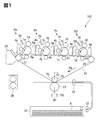
- FIG. 1 is an explanatory diagram of a configuration of an image forming apparatus according to an embodiment of the present invention.
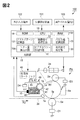
- FIG. 2 is an explanatory diagram of a configuration of a yellow image forming unit in the image forming apparatus according to the embodiment of the present invention.
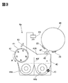
- FIG. 3 is an explanatory diagram of the configuration of the developing device in the image forming apparatus according to the embodiment of the present invention.
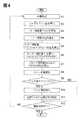
- FIG. 4 is a flowchart of conventional toner replenishment control.
- FIG. 5 is an explanatory diagram of a conversion table for the difference in TD ratio and the necessary toner replenishment amount.
- FIG. 6 is an explanatory diagram of a conversion table for video count values and toner consumption.
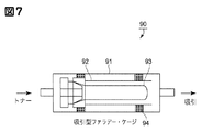
- FIG. 7 is an explanatory diagram of the configuration of a Faraday gauge for measuring the toner charge amount.
- FIG. 8 is a flowchart of toner replenishment control according to the embodiment of the present invention.
- FIG. 1 is an explanatory diagram of the configuration of the image forming apparatus according to the present embodiment.
- FIG. 2 is an explanatory diagram of the configuration of the yellow image forming unit.
- the image forming apparatus 100 is a tandem intermediate transfer type full color printer in which image forming portions Pa, Pb, Pc, and Pd of yellow, magenta, cyan, and black are arranged along an intermediate transfer belt 24. is there.
- image forming portion Pa a yellow toner image is formed on the photosensitive drum 1 a and is primarily transferred to the intermediate transfer belt 24.
- a magenta toner image is formed on the photosensitive drum 1 b and is primarily transferred to the yellow toner image on the intermediate transfer belt 24.
- a cyan toner image and a black toner image are formed on the photosensitive drums 1c and 1d, respectively, and are sequentially transferred onto the intermediate transfer belt 24 in order to be primarily transferred.
- the four-color toner images primarily transferred to the intermediate transfer belt 24 are conveyed to the secondary transfer portion T2 and secondarily transferred to the recording material P all at once.
- the recording material P drawn from the recording material cassette 20 is separated one by one by the separation roller 21 and sent to the registration roller 22.
- the registration roller 22 receives and waits for the recording material P in a stopped state, and sends the recording material P to the secondary transfer portion T2 in time with the toner image on the intermediate transfer belt 24.
- the recording material P onto which the four-color toner images have been secondarily transferred is heated and pressed by the fixing device 26 to fix the toner images on the surface, and then discharged to the outside of the machine body.
- the image forming portions Pa, Pb, Pc, and Pd are substantially the same except that the color of the toner used in the developing devices 4a, 4b, 4c, and 4d is different from yellow, magenta, cyan, and black.
- the image forming unit Pa will be described, and the image forming units Pb, Pc, and Pd will be described by replacing “a” at the end of the reference numerals attached to the components of the image forming unit Pa with “b”, “c”, and “d”. To do.
- the intermediate transfer belt 24 is supported around a tension roller 27, a drive roller 28, and a counter roller 25, and is driven by the drive roller 28 to rotate in the direction of arrow R2 at a process speed of 300 mm / sec.
- the secondary transfer roller 23 is in contact with the intermediate transfer belt 24 whose inner surface is supported by the counter roller 25 to form a secondary transfer portion T2.
- the belt cleaning device 29 rubs the intermediate transfer belt 24 with a cleaning blade, escapes the transfer to the recording material P, passes through the secondary transfer portion T2, and collects the transfer residual toner remaining on the intermediate transfer belt 24. .
- the document reading apparatus 101 includes a photoelectric conversion element that converts a document image such as a CCD into an electrical signal, and corresponds to yellow image information, magenta image information, cyan image information, and black image information of a document to be copied. Output image signal.
- the image forming unit Pa is provided around a photosensitive drum 1a, which is an example of a photoconductor as an image carrier, around a charging roller 2a, an exposure device 3a, a developing device 4a, a primary transfer roller 5a, and a cleaning device. 6a is arranged.
- the photosensitive drum 1a has a negatively charged photosensitive layer formed on the outer peripheral surface of an aluminum cylinder, and rotates in the direction of arrow R1 at a process speed of 300 mm / sec.
- the charging roller 2a is driven to rotate in contact with the photosensitive drum 1a, and an oscillating voltage obtained by superimposing an AC voltage on a DC voltage is applied from the power source D3, whereby the surface of the photosensitive drum 1a has a uniform negative polarity dark potential. Charge to VD.
- the exposure device 3a scans the scanning line image data obtained by developing the yellow separated color image with a rotating mirror, and writes an electrostatic image of the image on the surface of the charged photosensitive drum 1a.
- the developing device 4a uses a two-component developer to attach toner to the electrostatic image (exposed portion) of the photosensitive drum 1a, and reversely develops the toner image.
- the primary transfer roller 5 a presses the inner surface of the intermediate transfer belt 24 to form a primary transfer portion Ta between the photosensitive drum 1 a and the intermediate transfer belt 24.
- the cleaning device 6 a slides the cleaning blade on the photosensitive drum 1 a and collects the transfer residual toner remaining on the photosensitive drum 1 a by escaping from the transfer to the intermediate transfer belt 24.
- FIG. 3 is an explanatory diagram of the configuration of the developing device.
- the developing device 4a carries a developer on a developing sleeve 41, which is an example of a developer carrying member, and develops an electrostatic image on the photoreceptor (1a).
- the developer is stirred and charged by the pair of conveying screw members 44 a and 44 b and is carried on the developing sleeve 41.
- a developer cartridge 46 which is an example of a supply device, supplies a replenishment developer containing toner to the developer container 40.
- a toner concentration sensor 10 which is an example of a toner concentration detection unit, detects the developer circulating in the developing container 40 and outputs a signal corresponding to the proportion of toner in the developer.
- the developer container 40 contains a developer mainly composed of toner and carrier, and the ratio (toner concentration, TD ratio) expressed by the weight of the toner in the developer in the initial state is 8%.
- the TD ratio is not limited to 8% because it should be appropriately adjusted depending on the toner charge amount, the carrier particle size, the structure of the developing device 4a, and the like.
- a developing region facing the photosensitive drum 1a is opened, and a developing sleeve 41 made of a nonmagnetic material is rotatably disposed so as to be partially exposed from the opening.
- the magnet 42 which is a magnetic field generating means is constituted by a fixed cylindrical magnet having a plurality of magnetic poles of a predetermined pattern along the circumference of the developing sleeve 41.
- the carrier having the toner adsorbed on the surface by frictional charging is restrained on the developing sleeve 41 by the magnetic field generated by the magnet 42.
- the developing sleeve 41 rotates in the direction of arrow A (FIG. 3) during the developing operation, holds the developer in the developing container 40 in a layered state, carries and transports the developer, and supplies the developer to the developing region facing the photosensitive drum 1a. .
- the layer thickness of the developer carried on the developing sleeve 41 is regulated by a regulating member 43 provided in close proximity to the developing sleeve 41.
- the power source D4 applies to the developing sleeve 41 an oscillating voltage obtained by superimposing an AC voltage on a negative DC voltage Vdc.
- the developing sleeve 41 to which the negative DC voltage Vdc is applied is more negative than the electrostatic image (exposed portion) formed on the photosensitive drum (1a), and is charged to the negative polarity in the developer.
- the transferred toner is transferred from the developing sleeve 41 to the photosensitive drum 1a.
- the remaining developer that has developed the electrostatic image on the developing sleeve 41 is collected in the developing container 40 according to the rotation of the developing sleeve 41 and mixed with the developer conveyed by the conveying agitating screw 44a.
- conveying and agitating screws 44a and 44b which are examples of an agitating and conveying member that conveys the developer while stirring, are disposed in parallel with the developing sleeve 41.
- the developing sleeve 41 and the conveyance stirring screws 44a and 44b are connected to each other by a gear mechanism (not shown) outside the developing container 40, and are integrally rotated by a common driving motor.
- the space in the developing container 40 is divided into two spaces by a partition wall 40F, and a transport stirring screw 44a is disposed in the space on the developing sleeve 41 side, and a transport stirring screw 44b is disposed in the space on the developer cartridge 46 side. Openings (not shown) are formed at both ends in the longitudinal direction of the partition wall 40F in order to deliver the developer between the two spaces and circulate it in the developing container 40.
- the conveyance agitating screw 44a supplies the developer to the developing sleeve 41 while conveying the developer from the back side to the front side of the sheet.
- the conveyance agitation screw 44b mixes the replenishment developer supplied from the developer cartridge 46 with the circulating developer while conveying the developer from the near side to the far side of the sheet. In this way, the conveying and agitating screws 44a and 44b circulate the developer in the developing container 40, and agitate and charge the toner and the carrier by friction. (Two-component developer)
- a colored resin particle containing a binder resin, a colorant, and other additives as necessary, and an external additive such as colloidal silica fine powder are externally added.
- the toner is a negatively chargeable polyester resin produced by a pulverization method, and the volume average particle diameter is preferably 4 ⁇ m or more and 8 ⁇ m or less. In this embodiment, it was 5.5 ⁇ m.
- a Coulter counter TA-II type (manufactured by Coulter, Inc.) was used for measuring the volume average particle diameter of the toner. Then, an interface (manufactured by Nikka) and a CX-I personal computer (manufactured by Canon) for outputting the number average distribution and the volume average distribution from the measurement results were used.
- a 1% NaCl aqueous solution prepared using primary sodium chloride was used as the electrolytic aqueous solution for the measurement sample.
- a surfactant preferably an alkylbenzene sulfonate
- 0.5 to 50 mg of a measurement sample was added.
- the electrolytic aqueous solution in which the measurement sample was suspended was subjected to a dispersion treatment with an ultrasonic disperser for about 1 to 3 minutes, and then set in a Coulter counter TA-II type.
- a particle size distribution of 2 to 40 ⁇ m was measured using a 100 ⁇ m aperture as an aperture to obtain a volume average distribution. From the volume average distribution thus obtained, a volume average particle size was obtained.
- the carrier magnetic particles such as surface oxidized or unoxidized iron, nickel, cobalt, manganese, chromium, rare earth, and alloys thereof, or oxide ferrite can be used.
- the carrier has a volume average particle size of 20 to 50 ⁇ m, preferably 30 to 40 ⁇ m, and a resistivity of 1 ⁇ 10 7 ⁇ cm or more, preferably 1 ⁇ 10 8 ⁇ cm or more.
- the volume average particle diameter of the carrier is ⁇ 40 ⁇ m and the resistivity is 5 ⁇ 10 8 ⁇ cm.
- the volume average particle size of the carrier was measured using a laser diffraction particle size distribution measuring device HEROS (manufactured by JEOL Ltd.) in a logarithmic range of 0.5 to 350 ⁇ m on a volume basis. Then, from the result of counting the number of particles in each channel, the median diameter of 50% volume was defined as the volume average particle diameter.
- HEROS laser diffraction particle size distribution measuring device
- a sandwich type cell having a measurement electrode area of 4 cm and an electrode interval of 0.4 cm was used. Under pressure of 1 kg, an applied voltage E (V / cm) was applied between the electrodes of the cell, and the resistivity of the carrier was measured from the current flowing in the circuit.
- a resin carrier having a low specific gravity a resin carrier produced by mixing a phenolic binder resin with a magnetic metal oxide and a nonmagnetic metal oxide at a predetermined ratio and using a polymerization method can be used.
- a resin carrier has a volume average particle size of 35 ⁇ m, a true density of 3.6 to 3.7 (g / cm 3 ), and a magnetization of 53 (A ⁇ m 2 / kg).
- the amount of magnetization (A ⁇ m 2 / kg) of the magnetic carrier was measured using an oscillating magnetic field type magnetic property automatic recording apparatus manufactured by Riken Denshi Co., Ltd.
- the carrier packed in a cylindrical shape was determined by measuring the strength of magnetization of the carrier in an external magnetic field of 79.6 kA / m (1000 oersted).
- the two-component development method has advantages such as stability of image quality and durability of the apparatus as compared with other development methods.
- the mixing ratio (toner concentration: TD ratio) of the non-magnetic toner and the carrier in the developing container changes, and as a result, the toner charge amount (tribo) changes, thereby developing characteristics. Changes and the output image density changes. For this reason, in order to maintain a constant image formed image density, a toner replenishment control technique for accurately detecting the TD ratio of the developer and the image density and replenishing toner without excess or deficiency has been put into practical use. Yes. (Toner supply control)
- the two-component development method has advantages such as stability of image quality and durability of the apparatus as compared with other development methods.
- the mixing ratio of the non-magnetic toner and the carrier in the developing container toner concentration, hereinafter also referred to as TD ratio
- TD ratio the mixing ratio of the non-magnetic toner and the carrier in the developing container
- the toner charge amount changes, thereby developing characteristics.
- Changes and the output image density changes.
- the above-described control technology for toner replenishment that accurately detects the TD ratio of the developer and the image density and replenishes toner without excess or deficiency is put into practical use. Has been. 1) Video count control
- a video count detection unit (video count measurement means), which is an image ratio calculation unit for calculating an image ratio, counts the video count number of the density signal of the image information signal for each pixel, and is predicted based on the video count number
- the replenishment developer for consumption is replenished.
- video count control alone, there is no problem with short-term replenishment because there are fluctuations in toner supply replenishment and supply capacity variations of the replenishment developer supply device. There is an inconvenience that the TD ratio shifts due to the accumulation of. 2) Inductance control
- the TD ratio as the mixing ratio (toner concentration) of the nonmagnetic toner and the carrier is determined, and the replenishment developer is replenished.
- a patch image is formed during non-image formation of image formation, and the image density is measured by an image density detection sensor. Then, the density of the initial patch image obtained in advance and the density of the formed patch image are compared, and when a decrease in density is detected, the replenishment developer is replenished. 4) Triple control
- a triple control method using video count + inductance + patch detection ATR control is adopted to stabilize the output image density in a well-balanced manner. That is, the toner consumption amount is predicted and toner supply for the consumption amount is performed by feedforward, and the deviation of the supply amount from the reference value of the toner density is corrected by feedback by inductance control.
- the toner density may decrease more than expected due to the detection delay due to the time difference until the toner replenished by inductance control arrives after toner replenishment. Therefore, it is preferable from the viewpoint of improving the accuracy of toner replenishment that the toner consumption amount of the large frame is determined by the video count information and corrected by the inductance information.
- the target value of the toner density in the inductance control is appropriately changed according to the patch image density obtained by the patch detection ATR control. This is because it is well known that the carrier charging performance deteriorates due to toner adhesion to the carrier surface even at the same toner concentration, and the toner charge amount gradually decreases with durability. is there. (Basic principle and operation of toner replenishment in this embodiment)
- a device that uses a video count to calculate a toner replenishment amount corresponding to an expected toner consumption amount by feedforward and corrects a deviation of the toner density from a reference value by feedback.
- the toner in the developing device is hardly replaced, so that the toner is excessively agitated and the toner charge amount increases.
- the toner charge amount is lowered by increasing the toner density and reducing the developer friction machine.
- FIG. 4 is a flowchart of the conventional control
- FIG. 8 is a flowchart of the control of the present embodiment improved based on the flowchart of the conventional control.
- FIG. 5 is an explanatory diagram of a conversion table for the difference in TD ratio and the necessary toner replenishment amount for inductance control.
- FIG. 6 is an explanatory diagram of a conversion table of the video count value and the toner consumption amount regarding the video count control.
- the image forming apparatus 100 employs triple control type replenishment control based on video count control, inductance control, and patch image control for the toner replenishment amount.
- the patch image control frequency is increased to reduce the patch image formation frequency.
- the target value of the TD ratio in the developing device 4a is changed according to the patch image density detected by the patch image control (patch detection ATR control).
- the supply amount F (TD) of the supply developer is calculated (acquired) so that the TD ratio in the developing device 4a measured using the toner density sensor 10 becomes the target value of the changed TD ratio. To do. Then, the actual supply amount (final toner supply amount) is calculated by adding the toner consumption amount predicted (acquired) from the video count value to the calculated supply amount.
- the developer cartridge 46 as a replenishing developer supply device is substantially cylindrical for yellow, magenta, cyan, and black, and is attached to the image forming apparatus 100. It can be easily detached through the portion 20.
- a developer replenishing port 45 is provided on the upper wall 40A of the developing container 40 in the vicinity of the conveyance stirring screw 44b of the developing device 4a.
- the developer supply port 45 is provided with a developer supply screw 47 for conveying the supply developer.
- an amount of replenishment developer corresponding to the amount of toner consumed by image formation is supplied from the developer cartridge 46 through the developer replenishment port 45 by the rotational force and gravity of the developer replenishment screw 47 to the developer container. 40 is supplied.
- a replenishment method a known block replenishment method is adopted.
- toner is replenished to a preset one block toner replenishment amount (200 mg in the present embodiment) instead of replenishing an arbitrary toner replenishment amount as needed.
- This is a control for replenishment by rotating once. Since the toner replenishment amount increases or decreases within one cycle depending on the screw phase of the replenishment screw, in order to obtain a stable replenishment amount, a block replenishment method in which replenishment is always performed every cycle is preferable.
- the maximum number of replenishment per sheet is set to supply 2 blocks for A4 size and 4 blocks for A3 size.
- the toner supply control (toner replenishment control) of the control unit 15 (FIG. 2) for the developer cartridge 46 as a replenishment developer supply device uses the following three toner replenishment amount control units in combination. Is used.
- the output image density can be stabilized in the present embodiment.
- First control unit consumption replenishment control (video count control) for setting the toner replenishment amount to match the toner consumption amount for each image detected using the video count processing circuit 11 (FIG. 2)
- the video count processing circuit 11 processes the exposure signal (or the density signal of the image information signal) of the image being formed, and performs video count detection replenishment control for obtaining the toner consumption amount for each image.
- Second control unit toner density control (inductance control) for setting the toner replenishment amount so as to keep the TD ratio detected using the toner density sensor 10 (FIG. 2) constant.
- an inductance detection sensor that detects an apparent permeability change in the developer that decreases as the TD ratio increases is used to calculate the TD ratio.
- the toner density sensor 10 decreases in output when the TD ratio is high and carriers are relatively decreased, and the output is increased when the TD ratio is low and carriers are relatively increased.
- the TD ratio of the developer in the developing container 40 is detected by the toner density sensor 10, the density signal is compared with an initial reference signal stored in advance, and the TD ratio detection replenishment is performed based on the comparison result.
- toner charge amount control patch image control
- toner replenishment amount so as to keep the patch image detected using the image density sensor 7a (FIG. 2) constant.
- the image density sensor 7a detects a patch image formed on the photoconductor 1a under predetermined image forming conditions and outputs a signal corresponding to the amount of applied toner.
- the image density sensor 7a is a specular reflection type optical sensor that is disposed to face the photosensitive drum 1a and detects regular reflection from the surface of the photosensitive drum 1a by irradiating LED light. As the toner particles on the surface of the photosensitive drum 1a increase, the scattered reflected light increases and the regular reflected light decreases, so that an output signal corresponding to the amount of toner on the patch image can be obtained.
- the image density sensor 7a detects a density signal corresponding to the amount of applied toner of the patch image. Then, the density signal and the initial reference signal stored in advance are compared, and patch detection replenishment control is performed based on the comparison result.
- This patch detection replenishment control is executed to periodically correct the initial reference signal (Vtrg in FIG. 8) used in the TD ratio detection replenishment control which is the second control unit.
- the patch density formed on the photosensitive drum 1a is detected by the image density sensor 7a at the time of predetermined non-image formation at a predetermined number of intervals during continuous image formation, and the development characteristics are predicted.
- the target TD ratio of the developer in 4a (initial reference signal Vtrg in FIG. 8) is changed.
- the output Vsig of the detection unit (toner density sensor 10) in the second control unit is set so that the ratio of the toner in the developer converges on the target TD ratio Vtrg as the target ratio.
- the supply device (46) is controlled based on the above. (Conventional flowchart)
- the video count processing circuit 11 calculates a video count value during image formation (S2).
- the video count value is a count number obtained by counting the H level of the output signal obtained by pulse width modulation of the output of the image signal processing circuit 12 (FIG. 2) by the pulse width modulation circuit 13 (FIG. 2) for each pixel.
- the conversion table in FIG. 6 is a video count-replenishment amount conversion table, in which the horizontal axis represents the video count number N per document and the vertical axis represents the necessary toner replenishment amount F (V).
- the density signal Vsig of the TD ratio of the developer is detected using the toner density sensor 10 (FIG. 2) provided in the developing device 4a (S4).
- the target TD ratio Vtrg already obtained and recorded in the memory is compared with the density signal Vsig to obtain a difference ( ⁇ TD) (S5).
- ⁇ TD Vtrg ⁇ Vsig>0
- F toner replenishment amount
- the horizontal axis is a value obtained by multiplying the difference ⁇ TD of the actual signal value by an adjustment coefficient (correction coefficient) ⁇ such as the TD ratio sensitivity, and the positive direction on the vertical axis indicates the necessary toner supply amount and the negative direction. Is the excessive toner amount. Therefore, when ⁇ TD ⁇ 0, the replenishment toner amount F (TD) is calculated as ⁇ .
- B (C) F / 1 block supply amount (200 mg)
- B (C)> 1 replenishment control is performed for the number of blocks corresponding to an integer number (S8). At this time, the replenishment amount less than the one block replenishment amount is carried over to the next replenishment timing as F (REMAIN).
- a patch image is formed at an image interval (during non-image formation) on the photosensitive drum 1a at a predetermined interval during continuous image formation, patch detection replenishment control is executed, and TD is determined according to the measurement result of the patch image.
- the target TD ratio Vtrg of the ratio detection replenishment control is changed. Specifically, patch detection / replenishment control is executed if the timing determined for every 200 sheets of A4 landscape image formation is satisfied (YES in S9). However, if it is not the timing, image formation is continued (S9 ⁇ S1).
- an electrostatic latent image of a reference toner image (patch image) having a certain area is formed on the photosensitive drum 1a, and this is developed with a predetermined development contrast voltage. Then, the patch image is detected by the image density sensor 7a, and the density signal SigD is acquired (S10). Then, the target TD ratio Vtrg is calculated and set by comparing the obtained density signal SigD with the initial reference signal SigDref previously recorded in the memory (S11). This will be described in detail below.
- the target TD ratio (Vtrg) necessary for returning from the difference ⁇ OD to the initial density is calculated by the following equation. In the following equation, correction is performed by multiplying the actual signal value (SigD-SigDref) by the adjustment factor ⁇ such as the TD ratio sensitivity.
- Vtrg Vtrg + ⁇ * ⁇ OD
- Vtrg Vtrg + ⁇ * ⁇ OD
- Vtrg Vtrg + ⁇ * ⁇ OD If printing is to be continued after executing the patch detection ATR, the process returns to S1 to continue image formation (S12).
- the target TD ratio Vtrg of the inductance control unit is set to be high by the patch detection ATR executed at a low frequency. In this situation, when continuous printing of a high printing rate image is performed, toner replenishment with a large amount of toner consumption is frequently performed. descend.
- the printing rate is calculated from the video count value for each image forming sheet, and has a means for storing the 1000 most recent prints, and V1 (printing rate before 1 sheet) and V2 (printing before 2 sheets), respectively. Rate)... And stored as V1000 (printing rate before 1000 sheets). Then, an average printing rate for 10 prints (hereinafter referred to as S-DUTY) is calculated by averaging the latest printing rates V1 to V10 for each image formation. Similarly, an average printing rate for 1000 prints (hereinafter referred to as L-DUTY) is calculated by averaging the printing rates V1 to V1000 stored for each image formation (S13). 2) Calculation (acquisition) of rate of change of printing rate (variation of printing rate)
- the change rate ⁇ V of the print rate represented by the following equation is obtained as the change in the print rate by the following ratio calculation (S14). ).
- the change rate (variation amount) ⁇ V of the printing rate is measured for each image formation, and the adjustment coefficient (correction coefficient) ⁇ such as the TD ratio sensitivity related to the inductance control in the above-described triple control method is set as the printing rate. Control that changes based on the rate of change ⁇ V was used.
- the change rate ⁇ V of the print rate is compared with a preset change rate threshold value (threshold value) 10 (S15) and is greater than or equal to a predetermined amount (threshold value 10 or more), the image print rate is changed from a low print rate to a high print rate.
- the correction coefficient ⁇ is set to 0.1 (S16).
- the correction coefficient ⁇ is set to 0.7 (S17).
- the correction coefficient ⁇ is a coefficient that is multiplied by the difference ⁇ TD of the density signal Vsig with respect to the target TD ratio Vtrg. Therefore, increasing ⁇ increases the replenishment amount with respect to the deviation from the target value.
- ⁇ is too large, the ripple of the actual TD ratio tends to increase around the target TD ratio Vtrg, which is not preferable. This ripple is not detected as an increase in toner density until the replenished toner is transported to the toner density sensor position, and is further supplied during that time, resulting in a toner density exceeding the target toner density. The ratio tends to increase.
- the toner concentration in the developing unit naturally decreases by the amount that is less than the replenishment amount obtained from the difference ⁇ between Vtrg and Vsig, As a result, an effect of suppressing a decrease in toner charge amount can be obtained.
- control is performed so that ⁇ is returned to the normal value of 0.7 except during switching.
- ⁇ V ⁇ 10 when ⁇ V ⁇ 1 is detected, that is, when the average printing rate starts to return from a high printing rate to a low printing rate (S18), or patch detection ATR.
- S18 high printing rate to a low printing rate
- S19 control is performed to return ⁇ to 0.7 (S19).
- an upper limit and a lower limit may be provided for the toner density. Good. That is, it is determined whether or not the concentration signal Vsig is within the “lower limit TD ratio (VLlmt) and upper limit TD ratio (VHlmt) allowable in the system” recorded in the memory in advance (S20). As shown in FIG.
- the lower limit TD ratio (VLlmt) is calculated from the limit of image defects (white images due to carrier adhesion in this embodiment) that occur at the time of a low TD ratio. Specifically, the lower limit TD ratio (VLlmt) is lower than the initial TD ratio of 9%. The TD ratio was set to 4%.
- the upper limit TD ratio (VHlmt) is calculated from the limit of image defects that occur at the time of a high TD ratio (in this embodiment, so-called fog in which toner is developed on a white background), and specifically, the initial TD ratio is 9%. On the other hand, the lower limit TD ratio was set to 12%. (Evaluation results)
- FIG. 7 is an explanatory diagram of the configuration of a Faraday gauge capable of measuring the toner charge amount.
- the toner charge amount Q / M is measured using a Faraday gauge as shown in FIG.
- the Faraday gauge includes a double cylinder in which metal cylinders having different shaft diameters are arranged coaxially, and a toner collecting filter (filter) 93 for further taking toner into the inner cylinder of the double cylinder. Yes. If the inner cylinder 92 and the outer cylinder 91 of a double cylinder are insulated by an insulating member 94, and charged particles having a charge amount q are put into the inner cylinder 92, a metal cylinder having an amount of electricity q is as if due to electrostatic induction. It will be the same as it exists.
- the correction coefficients are ⁇ 0.7 ( ⁇ V ⁇ 10) and ⁇ 0.1 ( ⁇ V ⁇ 10), but the present invention is not limited to this.
- the target TD ratio Vtrg may be changed to a value smaller than the target TD ratio Vtrg before switching without changing the correction coefficient.
- a configuration in which a target TD ratio Vtrg of 10% before switching is reduced by 3% to 7% may be used.
- the toner density which is a factor of image density fluctuation with respect to the video count amount control replenishment amount F (V) at the time of switching from the low printing rate image to the high printing rate image.
- the video count amount control replenishment amount F (V) when the fluctuation of the printing rate during printing increases from the first value to the second value which is a predetermined value or a value exceeding this value.
- the ratio of the toner density control replenishment amount F (Td) is reduced.
- the present invention is not limited to this, and when the fluctuation of the printing rate during printing increases from the first value to the second value which is a variable value, the video count amount control replenishment amount F (V)
- the ratio of the toner density control replenishment amount F (Td) may be reduced.
- the toner density control supply amount F (Td) for the high printing rate image is smaller than the toner density control supply amount F (Td) for the low printing rate image. To be.
- an image forming apparatus capable of suppressing image density fluctuation that may occur when switching from a low printing rate image to a high printing rate image without significantly reducing productivity.
- Photosensitive drum 10 ... Toner density sensor 11 ... Video count processing circuit 15 ... Control unit 40 ; Developing container 41 ... Developing sleeve 46 ... Developer cartridge
Landscapes
- Physics & Mathematics (AREA)
- General Physics & Mathematics (AREA)
- Control Or Security For Electrophotography (AREA)
- Dry Development In Electrophotography (AREA)
Abstract
トナーとキャリアを含む現像剤を担持し感光体の静電像を現像する現像剤担持体と、現像剤を帯電させ現像剤担持体に担持させる現像容器と、トナーの濃度を検出する検出部と、画像全体の現像ドット数をカウントして積算するビデオカウント手段と、トナーの消費量に応じて補給用の現像剤を現像容器に供給する供給装置と、を備え、第1及び第2のトナー補給量をビデオカウント手段及び検出部の出力に基づき取得し、第1及び第2のトナー補給量に基づき決定される最終トナー補給量につき、プリント中の印字率の変動が第1の値から第2の値へ上昇する場合に、第1のトナー補給量に対する第2のトナー補給量の比を小さくする。
Description
本発明は、電子写真複写機やレーザービームプリンタ等の像担持体上に形成された静電潜像をトナー像に現像する現像装置を備えた画像形成装置に関するものである。
トナー(非磁性)とキャリア(磁性)を主成分とする現像剤(二成分現像剤)を用いて、感光体に書き込まれた静電像をトナー像に現像する画像形成装置が広く用いられている。二成分現像剤を用いる現像装置では、所定の帯電/露光条件で形成した静電像が所定のトナー載り量で現像されるように、現像剤に占めるトナー濃度を調整してトナー帯電量を一定に保っている。
トナー帯電量を一定に保つ制御では、トナー帯電量が減少すると、同じ静電像でもトナー載り量が増えて画像濃度が高まるため、トナー補給制御としてトナーの割合を減らして、現像剤の摩擦機会を増すことにより、トナー帯電量を高めている。一方、トナーの帯電量が増加すると同じ静電像でもトナー載り量が減って画像濃度が下がるため、トナー補給制御としてトナーの割合を増やして現像剤の摩擦機会を減らすことにより、トナー帯電量を低下させている。
トナー補給制御に関し、特開平05−027527号公報には、ビデオカウント制御として、露光装置の光源に供給される二値変調された画像全体の現像ドット数をカウントして積算するビデオカウント手段が示される。これは、画像形成される画像データや露光信号を処理して、1枚の画像を現像する際に消費されるトナー量を計算し、消費されるトナー量に見合った量の補給用現像剤を補給することにより、現像剤に占めるトナーの割合の変動を抑制するものである。
また、特開平01−182750号公報には、インダクタンス制御として、キャリアの比率が高まると現像剤(二成分現像剤)の透磁率が高まることを利用してトナー濃度に応じた信号を出力する透磁率センサ(インダクタンスセンサ)を用いた検出部が示される。
また、特開平06−149057号公報には、パッチ画像制御として、連続画像形成中の画像間隔に形成したパッチ画像に、LED光を照射して、正反射光量を検出することにより、パッチ画像のトナー載り量に応じた信号を出力する光学センサが示される。これは、所定の帯電/露光条件で形成したパッチ画像のトナー載り量が所定値に収束するように、補給用現像剤を現像容器に補給して、現像剤(二成分現像剤)のトナー濃度を変化させるものである。いわゆる、パッチ検ATR(AutoTonerReplenishing)と言われるものである。
さらに、特開2011−48118号公報には、トリプル制御として、ビデオカウント制御とインダクタンス制御とパッチ検ATR制御を用いて、バランス良く出力画像濃度を安定化するトナー補給制御が示される。ここでは、ビデオカウント手段を用いて予想トナー消費量に相当するトナー補給量をフィードフォワードで算出し、またインダクタンス制御部によってトナー濃度が基準値に対してのズレをフィードバックで補正する制御が為されている。
トリプル制御に関し、トナー消費量が多いケースにおいてインダクタンス制御のみを用いると、トナー補給後にインダクタンス制御により補給するトナーが到達するまでの時間差による検知遅れで、トナー濃度が予想以上に低下する場合がある。従って、大枠のトナー補給量をビデオカウント情報で決定し、インダクタンス情報によって補正することが、トナー補給の精度向上の観点で好ましい。
また、同一トナー濃度であってもキャリア表面へのトナー付着などにより、キャリア帯電性能が低下して、耐久に伴い緩やかにトナー帯電量が低下することが良く知られている。従って、低頻度のパッチ検ATRによって、インダクタンス制御によるトナー濃度目標値を変更することが好ましい。
このように、トリプル制御で、トナー消費量が多い使用ケースや、耐久に伴ってキャリア帯電性能の変化する場合でも、著しく生産性を落とすことなく出力画像濃度を安定化させることが可能になっている。
しかしながら、特開2011−48118号公報の制御を用いても出力画像濃度が変動する場合があった。具体的には、印字率の低い画像(以下、低印字率画像と呼ぶ)を連続してプリントした直後に、印字率の高い画像(以下、高印字率画像と呼ぶ)を連続してプリントする場合である。
すなわち、低印字率画像を連続してプリントした場合、現像器内のトナー入れ替えが少ないためにトナーとキャリアの摩擦帯電が過剰になされトナー帯電量が高くなる傾向がある。従って、これを抑制するために、特開2011−48118号公報の制御の場合、低頻度で実行されるパッチ検ATRによって、インダクタンス制御部の目標トナー濃度を高く設定する。
この状況で、次に高印字率画像の連続プリントを実行した場合、多量のトナー消費に伴うトナー補給が高頻度で実行されることで、攪拌時間が短くなることでトナー帯電量が急速に低下する。この急速なトナー帯電量の低下に対して、特開2011−48118号公報の制御の場合、パッチ検ATR制御の頻度が低いとき、インダクタンス制御によるトナー濃度の目標値変更が追従できずトナー帯電量が低下しつづけ、結果として画像濃度上昇が生じることがある。
そして、特開2011−48118号公報の制御の場合、低印字率連続時にインダクタンス制御部の目標トナー濃度を高く設定しているため、高印字率連続時のトナー帯電量の低下は、攪拌時間不足とトナー濃度設定高の2重要因で顕著になる。これに対して、トナー帯電量低下に追従するようパッチ検ATR制御を高頻度実行した場合は、生産性低下が生じることとなり好ましくない。
本発明の目的は、低印字率画像から高印字率画像への切り替え時に発生し得る画像濃度変動を、生産性を著しく落とすことなく抑制できる画像形成装置を提供することにある。
本発明の一態様によれば、像担持体と、トナーとキャリアを含む現像剤を担持して前記像担持体に形成された静電像を現像する現像剤担持体と、前記現像剤担持体に供給する現像剤を収容する現像容器と、前記現像容器内の現像剤に対するトナーの濃度を検出する検出部と、前記現像容器にトナーを供給する供給装置と、前記像担持体上に形成される画像の画像比率に基づいて取得される第1のトナー補給量と、前記検出部の出力に基づきトナーの濃度が目標値になるように取得される第2のトナー補給量と、に基づいて前記供給装置から前記現像容器に補給するトナー量を制御する制御部と、を有し、前記制御部は、連続した所定数の画像の画像比率に対して連続した複数の画像の画像比率が高く、連続した所定数の画像の画像比率に対して連続した複数の画像の画像比率の変動が所定値よりも大きくなった場合には、前記変動が所定値よりも小さい場合の前記第2のトナー補給量に比べてより前記第2のトナー補給量が少なくなるように前記第2のトナー補給量を制御する画像形成装置が提供される。
本発明の他の態様によれば、像担持体と、トナーとキャリアを含む現像剤を担持して前記像担持体に形成された静電像を現像する現像剤担持体と、前記現像剤担持体に供給する現像剤を収容する現像容器と、前記現像容器内の現像剤に対するトナーの濃度を検出する検出部と、前記現像容器にトナーを供給する供給装置と、前記像担持体上に形成される画像の画像比率に基づいて取得される第1のトナー補給量と、前記検出部の出力に基づきトナーの濃度が目標値になるように取得される第2のトナー補給量と、に基づいて前記供給装置から前記現像容器に補給するトナー量を制御する制御部と、を有し、前記制御部は、5%以下の第一の画像比率の画像を連続して予め設定した数の画像形成後に30%以上の第二の画像比率の画像を連続して画像形成を開始した後に補給するトナー量は、30%以上の第二の画像比率の画像を前記予め設定した数の画像形成後に補給するトナー量よりも少なくなるようにトナー量を制御する画像形成装置が提供される。
本発明によれば、低印字率画像から高印字率画像への切り替え時に発生し得る画像濃度変動を、生産性を著しく落とすことなく、抑制できる。
図1は本発明の実施形態に係る画像形成装置の構成の説明図である。
図2は本発明の実施形態に係る画像形成装置におけるイエローの画像形成部の構成の説明図である。
図3は本発明の実施形態に係る画像形成装置における現像装置の構成の説明図である。
図4は従来例のトナー補給制御のフローチャートである。
図5はTD比の差分と必要トナー補給量の換算テーブルの説明図である。
図6はビデオカウント値とトナー消費量の換算テーブルの説明図である。
図7はトナー帯電量を測定するファラデー・ゲージの構成の説明図である。
図8は本発明の実施形態に係るトナー補給制御のフローチャートである。
以下、本発明の実施の形態について図面を用いて説明する。
《第1の実施形態》
(画像形成装置)
《第1の実施形態》
(画像形成装置)
図1は、本実施形態に係る画像形成装置の構成の説明図である。図2は、イエローの画像形成部の構成の説明図である。図1に示すように、画像形成装置100は、中間転写ベルト24に沿ってイエロー、マゼンタ、シアン、ブラックの画像形成部Pa、Pb、Pc、Pdを配列したタンデム型中間転写方式のフルカラープリンタである。画像形成部Paでは、感光ドラム1aにイエロートナー像が形成されて中間転写ベルト24に一次転写される。
画像形成部Pbでは、感光ドラム1bにマゼンタトナー像が形成されて中間転写ベルト24のイエロートナー像に重ねて一次転写される。画像形成部Pc、Pdでは、それぞれ感光ドラム1c、1dにシアントナー像、ブラックトナー像が形成されて同様に中間転写ベルト24に順次重ねて一次転写される。
中間転写ベルト24に一次転写された四色のトナー像は、二次転写部T2へ搬送されて記録材Pへ一括して二次転写される。記録材カセット20から引き出された記録材Pは、分離ローラ21で1枚ずつに分離してレジストローラ22へ送り出される。レジストローラ22は、停止状態で記録材Pを受け入れて待機させ、中間転写ベルト24のトナー像にタイミングを合わせて記録材Pを二次転写部T2へ送り込む。そして、四色のトナー像を二次転写された記録材Pは、定着装置26で加熱加圧を受けて表面にトナー像を定着された後に、機体外部へ排出される。
画像形成部Pa、Pb、Pc、Pdは、現像装置4a、4b、4c、4dで用いるトナーの色がイエロー、マゼンタ、シアン、ブラックと異なる以外は、実質的にほぼ同一に構成される。以下では、画像形成部Paについて説明し、画像形成部Pb、Pc、Pdについては、画像形成部Paの構成部材に付した符号末尾のaをb、c、dに読み替えて説明されるものとする。
中間転写ベルト24は、テンションローラ27、駆動ローラ28、及び対向ローラ25に掛け渡して支持され、駆動ローラ28に駆動されて300mm/secのプロセススピードで矢印R2方向に回転する。二次転写ローラ23は、対向ローラ25に内側面を支持された中間転写ベルト24に当接して二次転写部T2を形成する。二次転写ローラ23に電源D2から直流電圧が印加されることによって、中間転写ベルト24に担持されたトナー像が記録材Pへ二次転写される。
ベルトクリーニング装置29は、中間転写ベルト24にクリーニングブレードを摺擦させて、記録材Pへの転写を逃れて二次転写部T2を通過して中間転写ベルト24に残った転写残トナーを回収する。
図2に示すように、被複写原稿は、原稿読取装置101で読み取られる。原稿読取装置101は、CCD等の原稿画像を電気信号に変換する光電変換素子を有しており、被複写原稿のイエロー画像情報、マゼンタ画像情報、シアン画像情報、ブラック画像情報に、それぞれ対応した画像信号を出力する。
画像形成部Paは、図1に示すように、像担持体である感光体の一例である感光ドラム1aの周囲に、帯電ローラ2a、露光装置3a、現像装置4a、一次転写ローラ5a、クリーニング装置6aを配置している。感光ドラム1aは、アルミニウムシリンダの外周面に負極性の帯電極性の感光層が形成され、300mm/secのプロセススピードで矢印R1方向に回転する。
帯電ローラ2aは、感光ドラム1aに当接して従動回転し、直流電圧に交流電圧を重畳した振動電圧を電源D3から印加されることにより、感光ドラム1aの表面を一様な負極性の暗部電位VDに帯電させる。露光装置3aは、イエローの分解色画像を展開した走査線画像データをON−OFF変調したレーザービームを回転ミラーで走査して、帯電した感光ドラム1aの表面に画像の静電像を書き込む。現像装置4aは、後述するように、二成分現像剤を用いて、感光ドラム1aの静電像(露光部)にトナーを付着させて、トナー像を反転現像する。
一次転写ローラ5aは、中間転写ベルト24の内側面を押圧して、感光ドラム1aと中間転写ベルト24との間に一次転写部Taを形成する。電源D1から一次転写ローラ5aへ正極性の直流電圧が印加されることにより、感光ドラム1aに担持されたトナー像が、一次転写部Taを通過する中間転写ベルト24へ一次転写される。クリーニング装置6aは、感光ドラム1aにクリーニングブレードを摺擦させて、中間転写ベルト24への転写を逃れて感光ドラム1aに残った転写残トナーを回収する。
(現像装置)
(現像装置)
図3は、現像装置の構成の説明図である。図3に示すように、現像装置4aは、現像剤担持体の一例である現像スリーブ41に現像剤を担持して感光体(1a)の静電像を現像する。現像容器40は、一対の搬送スクリュー部材44a、44bによって現像剤を攪拌、帯電させて現像スリーブ41に担持させる。供給装置の一例である現像剤カートリッジ46は、トナーを含む補給用現像剤を現像容器40に供給する。トナー濃度検出部の一例であるトナー濃度センサ10は、現像容器40内を循環する現像剤を検出して現像剤に占めるトナーの割合に応じた信号を出力する。
現像容器40には、トナーとキャリアを主成分とする現像剤が収容されており、初期状態の現像剤に占めるトナーの重量で示した割合(トナー濃度、TD比)は8%である。なお、TD比は、トナー帯電量、キャリア粒径、現像装置4aの構造等で適正に調整されるべきものであるから、8%に限定されるものではない。
現像装置4aは、感光ドラム1aに対向した現像領域が開口しており、この開口部から一部露出させて、非磁性材料で構成される現像スリーブ41が回転可能に配置されている。磁界発生手段であるマグネット42は、現像スリーブ41の円周に沿って、所定のパターンの複数の磁極を有する固定の円柱状マグネットで構成される。摩擦帯電によって表面にトナーを吸着したキャリアは、マグネット42が発生する磁界によって現像スリーブ41上に拘束される。
現像スリーブ41は、現像動作時には矢印A方向(図3)に回転し、現像容器40内の現像剤を層状に保持して担持搬送し、感光ドラム1aと対向する現像領域に現像剤を供給する。現像スリーブ41に担持する現像剤の層厚は、現像スリーブ41と近接対向して設けられた規制部材43によって規制される。
電源D4は、負極性の直流電圧Vdcに交流電圧を重畳した振動電圧を現像スリーブ41に印加する。負極性の直流電圧Vdcが印加された現像スリーブ41は、感光ドラム(1a)に形成されている静電像(露光部)よりも相対的に負極性になり、現像剤中の負極性に帯電したトナーが現像スリーブ41から感光ドラム1aへ移転する。現像スリーブ41上の静電像を現像した残りの現像剤は、現像スリーブ41の回転に従って現像容器40内に回収され、搬送攪拌スクリュー44aによって搬送される現像剤に混合される。
現像容器40内には、現像剤を攪拌しながら搬送する攪拌搬送部材の一例である搬送攪拌スクリュー44a、44bが現像スリーブ41と平行に配設される。現像スリーブ41及び搬送攪拌スクリュー44a、44bは、現像容器40の外側で、図示しないギア機構によって連結され、共通の駆動モータによって一体に回転駆動される。
現像容器40内の空間は、仕切壁40Fによって2つの空間に仕切られ、現像スリーブ41側の空間に搬送攪拌スクリュー44a、現像剤カートリッジ46側の空間に搬送攪拌スクリュー44bが配設されている。仕切壁40Fの長手方向の両端部には、2つの空間の間で現像剤を受け渡して現像容器40内で循環させるため、不図示の開口部が形成されている。
搬送攪拌スクリュー44aは、紙面の奥側から手前側に向かって現像剤を搬送しつつ、現像スリーブ41に現像剤を供給する。搬送攪拌スクリュー44bは、逆に、紙面の手前側から奥側に向かって現像剤を搬送しつつ、現像剤カートリッジ46から供給された補給用現像剤を循環する現像剤に混合する。このようにして、搬送攪拌スクリュー44a、44bは、現像剤を現像容器40内で循環させるとともに、トナーとキャリアとを攪拌して摩擦帯電させる。
(二成分現像剤)
(二成分現像剤)
本実施形態における二成分現像剤のトナーは、結着樹脂、着色剤、そして、必要に応じてその他の添加剤を含む着色樹脂粒子と、コロイダルシリカ微粉末のような外添剤が外添されている着色粒子とを有している。そして、トナーは、粉砕法により製造した負帯電性のポリエステル系樹脂であり、体積平均粒径は4μm以上、8μm以下が好ましい。本実施形態では5.5μmであった。
トナーの体積平均粒径の測定には、コールターカウンターTA−II型(コールター社製)を用いた。そして、測定結果から個数平均分布、体積平均分布を出力するためのインターフェース(日科機製)及びCX−Iパーソナルコンピュータ(キヤノン製)を使用した。
測定試料の電解水溶液として、一級塩化ナトリウムを用いて調製した1%NaCl水溶液を使用した。電解水溶液100~150ml中に分散剤として界面活性剤、好ましくはアルキルベンゼンスルホン酸塩を0.1ml加え、測定試料を0.5~50mg加えた。測定試料を懸濁した電解水溶液は、超音波分散器で約1~3分間分散処理を行なった後にコールターカウンターTA−II型にセットした。
コールターカウンターTA−II型では、アパーチャーとして100μmアパーチャーを用いて2~40μmの粒子の粒度分布を測定して体積平均分布を求めた。こうして求めた体積平均分布より、体積平均粒径を得た。
キャリアは、表面酸化又は未酸化の鉄、ニッケル、コバルト、マンガン、クロム、希土類などの金属、及びそれらの合金、或は酸化物フェライトなどの磁性粒子が使用可能であり、磁性粒子の製造法は特に制限されない。キャリアは、体積平均粒径が20~50μm、好ましくは30~40μmであり、抵抗率が1×10⁷Ωcm以上、好ましくは1×10⁸Ωcm以上である。本実施形態では、キャリアの体積平均粒径はφ40μm、抵抗率が5×10⁸Ωcmである。
キャリアの体積平均粒径は、レーザー回折式粒度分布測定装置HEROS(日本電子製)を用いて、体積基準で粒径0.5~350μmの範囲を32対数分割して測定した。そして、それぞれのチャンネルにおける粒子数をカウントした結果から体積50%のメジアン径をもって体積平均粒径とした。
キャリアの抵抗率は、測定電極面積4cm、電極間隔0.4cmのサンドイッチタイプのセルを用いた。1kgの重量の加圧下で、セルの両電極間に印加電圧E(V/cm)を印加して、回路に流れた電流からキャリアの抵抗率を測定した。
更に、低比重のキャリアとして、フェノール系のバインダー樹脂に磁性金属酸化物及び非磁性金属酸化物と所定の比で混合し、重合法により製造した樹脂キャリアを使用することができる。このような樹脂キャリアの体積平均粒径は35μm、真密度は3.6~3.7(g/cm3)、磁化量は53(A・m2/kg)である。
磁性キャリアの磁化量(A・m2/kg)は、キャリアの磁気特性を理研電子(株)製の振動磁場型磁気特性自動記録装置を用いて測定した。円筒状にパッキングしたキャリアを79.6kA/m(1000エルステッド)の外部磁場中において、キャリアの磁化の強さを測定することにより求めた。
二成分現像方式は、他の現像方式と比較して、画質の安定性、装置の耐久性などの長所を備えている。一方、トナーが消費されることにより、現像容器内の非磁性トナーとキャリアの混合比(トナー濃度:TD比)が変化し、その結果、トナー帯電量(トリボ)が変化することで、現像特性が変化して出力画像濃度が変化する問題がある。このため、画像形成された画像濃度を一定に維持するために、現像剤のTD比や画像濃度を正確に検出して、過不足の無いトナーを補給するトナー補給の制御技術が実用化されている。
(トナー補給制御)
(トナー補給制御)
二成分現像方式は、他の現像方式と比較して、画質の安定性、装置の耐久性などの長所を備えている。一方、トナーが消費されることにより、現像容器内の非磁性トナーとキャリアの混合比(トナー濃度、以降TD比とも呼ぶ)が変化し、その結果、トナー帯電量が変化することで、現像特性が変化して出力画像濃度が変化する問題がある。このため、画像形成された画像濃度を一定に維持するために、現像剤のTD比や画像濃度を正確に検出して、過不足の無いトナーを補給するトナー補給の上述した制御技術が実用化されている。
1)ビデオカウント制御
1)ビデオカウント制御
画像比率を算出する画像比率算出部であるビデオカウント検知部(ビデオカウント計測手段)が、画素ごとの画像情報信号の濃度信号のビデオカウント数をカウントし、ビデオカウント数に基づいて予測されたトナー消費量分の補給用現像剤が補給される。しかし、ビデオカウント制御のみでは、消費トナーの補給変動や、補給用現像剤の供給装置の供給能力バラツキが有るため、短期的な補給に対しては問題ないが、長期間の変動の変動もしくはばらつきの蓄積で、TD比がずれていくという不都合がある。
2)インダクタンス制御
2)インダクタンス制御
低下する現像剤の見かけの透磁率変化を検知(インダクタンス検知)することで、非磁性トナーとキャリアの混合比(トナー濃度)としてのTD比を判別して、補給用現像剤が補給される。
3)パッチ画像制御
3)パッチ画像制御
画像形成の非画像形成時にパッチ画像を作像して、画像濃度検知センサにより画像濃度を測定する。そして、予め求めた初期パッチ画像と作像したパッチ画像の濃度を比較し、濃度低下を検知したら補給用現像剤を補給し、濃度上昇を検知したら補給停止を繰り返す。
4)トリプル制御
4)トリプル制御
本実施形態では、ビデオカウント+インダクタンス+パッチ検ATR制御によるトリプル制御方式を採用して、バランス良く出力画像濃度を安定化させる。すなわち、トナー消費量を予測してフィードフォアードで消費分のトナー補給を実施しつつ、補給量バラツキをインダクタンス制御によってトナー濃度の基準値に対してのズレをフィードバックで補正する。
インダクタンス制御のみでは、たとえば、トナー消費量が多いケースで、トナー補給後にインダクタンス制御で補給したトナーが到達するまでの時間差による検知遅れでトナー濃度が予想以上に低下する場合がある。従って、大枠のトナー消費量をビデオカウント情報で決定し、インダクタンス情報によって補正することが、トナー補給の精度向上の観点で好ましい。
また、パッチ検ATR制御によって求められたパッチ画像濃度に応じて、インダクタンス制御におけるトナー濃度の目標値を適宜変更する。これは、同一トナー濃度であってもキャリア表面へのトナー付着などにより、キャリア帯電性能が低下して、耐久に伴い緩やかにトナー帯電量が低下することが良く知られ、これに対処するためである。
(本実施形態におけるトナー補給の基本的な原理・作用)
(本実施形態におけるトナー補給の基本的な原理・作用)
ビデオカウントを用い予想トナー消費量に相当するトナー補給量をフィードフォワードで算出し、トナーの濃度の基準値に対するズレをフィードバックで補正する装置を前提とする。そして、低印字率画像を連続してプリントするときは、現像器内のトナーの入れ替わりが少ないため、トナーが過剰撹拌されてトナー帯電量が増大する。このトナー帯電量の増大を抑制するため、トナー濃度を増やして現像剤の摩擦機械を減らすことでトナー帯電量を低下させる。
ここで、低印字率画像をプリントした直後に高印字率画像、画像比率をプリントする場合、低印字率画像に対して設定された高い状態のトナー濃度という点、かつ多量のトナー補給がされる高印字率画像のプリントという点で、トナー帯電量が急激に低下する。
一方、ATRパッチ制御は、生産性を考慮して低頻度実施としているため目標トナー濃度を下げることができないため、トナー帯電量が低いままプリントされ、画像濃度が濃い(高い)方向に変動する(色味変動を生ずる)。
そこで、本実施形態では、低印字率画像をプリントした直後に高印字率画像をプリントする場合、インダクタンス制御に従うとトナー補給がされ続けるためトナー帯電量が低下してしまうこととなるため、インダクタンス補給係数を小さくする。すなわち、実質的にビデオカウントを用いたトナー補給制御のみとする。
(従来例に対する本実施形態のフローチャート)
(従来例に対する本実施形態のフローチャート)
図4は従来制御のフローチャート、図8は従来制御のフローチャートを基に改善された本実施形態の制御のフローチャートである。図5は、インダクタンス制御に関しTD比の差分と必要トナー補給量の換算テーブルの説明図である。図6は、ビデオカウント制御に関しビデオカウント値とトナー消費量の換算テーブルの説明図である。
図1に示す本実施形態の画像形成装置100では、トナー補給量に関しビデオカウント制御、インダクタンス制御、パッチ画像制御によるトリプル制御方式の補給制御を採用している。そして、生産性を著しく落すことがないように、パッチ画像制御の実行間隔を長くとってパッチ画像の形成頻度を低くしている。更に、本実施形態では、パッチ画像制御(パッチ検ATR制御)で検出したパッチ画像濃度に応じて現像装置4a内のTD比の目標値を変更している。
これにより、トナー濃度センサ10を用いて測定した現像装置4a内のTD比が、変更されたTD比の目標値になるように、補給用現像剤の補給量F(TD)を算出(取得)する。そして、算出された補給量に対して、ビデオカウント値から予測(取得)されるトナー消費量分を加算することで、実補給量(最終トナー補給量)を算出する。
さて、図3に示すように、補給用の現像剤供給装置としての現像剤カートリッジ46は、イエロー、マゼンタ、シアン、ブラック用全てが略円筒形であり、画像形成装置100に対しては、装着部20を介して容易に脱着可能とされている。
図3で、現像装置4aの搬送攪拌スクリュー44bの近傍の現像容器40の上壁40Aには、現像剤補給口45が設けられている。現像剤補給口45には、補給用現像剤を搬送するための現像剤補給スクリュー47が設けられている。現像装置4aにおいては、画像形成によって消費されたトナー量に相当する量の補給用現像剤は、現像剤補給スクリュー47の回転力と重力によって、現像剤カートリッジ46から現像剤補給口45を通して現像容器40内に供給される。なお、補給方法としては、公知のブロック補給方式を採用している。
ブロック補給方式とは、任意のトナー補給量を随時補給でなく、予め設定した1ブロックトナー補給量(本実施形態では200mg)までトナー補給をため込み、1ブロック補給量200mg毎に補給スクリュー32を1周回転することで補給する制御である。補給スクリューのスクリュー位相によって1周期内でトナー補給量が増減するために、安定した補給量を得るためには常に1周期毎に補給するブロック補給方式が好ましい。本実施形態では、A4サイズで2ブロック補給、A3サイズで4ブロック補給を1枚当たりに補給する最大補給数と設定している。
本実施形態において、補給用の現像剤供給装置としての現像剤カートリッジ46に対する制御部15(図2)のトナー供給制御(トナー補給制御)は、以下の3つのトナー補給量制御部を併用する方式を用いている。このように、第1、第2、そして第3制御部を組み合わせることで、本実施形態では、出力画像濃度を安定化させることが可能となる。
1)第1制御部部:ビデオカウント処理回路11(図2)を用いて検出した画像ごとのトナー消費量に見合うようにトナー補給量を設定する消費量補充制御(ビデオカウント制御)
1)第1制御部部:ビデオカウント処理回路11(図2)を用いて検出した画像ごとのトナー消費量に見合うようにトナー補給量を設定する消費量補充制御(ビデオカウント制御)
本制御部では、画像形成中の画像の露光信号(又は画像情報信号の濃度信号)をビデオカウント処理回路11が処理して画像ごとのトナー消費量を求めるビデオカウント検知補給制御を行う。
2)第2制御部:トナー濃度センサ10(図2)を用いて検出されるTD比を一定に保つようにトナー補給量を設定するトナー濃度制御(インダクタンス制御)
2)第2制御部:トナー濃度センサ10(図2)を用いて検出されるTD比を一定に保つようにトナー補給量を設定するトナー濃度制御(インダクタンス制御)
トナー濃度センサ10として、TD比が高くなることで低下する現像剤中の見かけの透磁率変化を検知してTD比を算出するインダクタンス検知センサを採用した。トナー濃度センサ10は、TD比が高くなってキャリアが相対的に減ると出力が低下し、TD比が低くなってキャリアが相対的に増えると出力が上昇する。
本制御部では、現像容器40内の現像剤のTD比をトナー濃度センサ10で検出し、この濃度信号と予め記憶された初期基準信号とを比較し、その比較結果に基づいてTD比検知補給制御を行う。
3)第3制御部:画像濃度センサ7a(図2)を用いて検出されるパッチ画像を一定に保つようにトナー補給量を設定するトナー帯電量制御(パッチ画像制御)
3)第3制御部:画像濃度センサ7a(図2)を用いて検出されるパッチ画像を一定に保つようにトナー補給量を設定するトナー帯電量制御(パッチ画像制御)
画像濃度センサ7aは、感光体1aに所定の画像形成条件で形成されたパッチ画像を検出してトナー載り量に応じた信号を出力する。画像濃度センサ7aは感光ドラム1aに対向配置され、LED光を照射して感光ドラム1a表面からの正反射を検出する正反射型の光学センサである。感光ドラム1aの表面のトナー粒子が増えると、散乱反射光が増えて正反射光が減少するため、パッチ画像のトナー載り量に応じた出力信号が得られる。
本制御部に関しては、感光ドラム1a上に所定の画像形成条件で中間階調のパッチ画像を形成した後、パッチ画像のトナー載り量に対応する濃度信号を画像濃度センサ7aで検出する。そして、濃度信号と予め記憶された初期基準信号とを比較し、その比較結果に基づいてパッチ検知補給制御を行う。
このパッチ検知補給制御は、第2制御部であるTD比検知補給制御で用いる初期基準信号(図8のVtrg)を定期的に補正するために実行される。このような本制御は、連続画像形成中の所定枚数間隔で所定の非画像形成時に、感光ドラム1a上に作像したパッチ画像を画像濃度センサ7aで検出して現像特性を予測し、現像装置4a内の現像剤の目標TD比(図8の初期基準信号Vtrg)を変更していく。
そして、このような目標割合の設定後は、現像剤に占めるトナーの割合が目標割合としての目標TD比Vtrgに収束するように、第2制御部における検出部(トナー濃度センサ10)の出力Vsigに基づいて供給装置(46)を制御する。
(従来例のフローチャート)
(従来例のフローチャート)
本実施形態のフローチャートを説明する前に、本実施形態のフローチャートの前提となる従来例のフローチャートを説明する。図4において、画像形成が開始すると(S1)、ビデオカウント処理回路11(図2)が画像形成中のビデオカウント値を算出する(S2)。ビデオカウント値は、画像信号処理回路12(図2)の出力をパルス幅変調回路13(図2)がパルス幅変調した出力信号のHレベルを画素毎にカウントしたカウント数である。
このカウント数を原稿紙サイズ全体で積算することにより、原稿1枚当たりの画像全体の現像ドット数に対応するビデオカウント数Nが算出される。また、ビデオカウント数からプリントの印字率が求められ、本従来例においてはある1色についてA4サイズ用紙片面の全面ベタ画像(印字率100%の画像)のビデオカウント数N=512とする。例えば、ビデオカウント=26の場合の印字率は、比率計算で5%と求めている。
その後、算出されたビデオカウント数Nで図6の換算テーブルを参照して、トナー消費量、つまり必要トナー補給量F(V)(以下、ビデオカウントによる制御補給量と呼ぶ)を算出する(S2)。図6の換算テーブルは、ビデオカウント—補給量変換テーブルであって、横軸が原稿1枚当たりのビデオカウント数Nであり、縦軸が必要トナー補給量F(V)である。
ここで、現像装置4a内に備えたトナー濃度センサ10(図2)を用いて現像剤のTD比の濃度信号Vsigを検知する(S4)。次に、既に求められてメモリに記録されている目標TD比Vtrgと濃度信号Vsigとが比較されて、差分(ΔTD)が求められる(S5)。
更に詳述すると、ΔTD=Vtrg−Vsig>0の場合、目標TD比に対して実際のTD比が低いと判断し、図5の換算テーブルをΔTDで参照して、トナー補給量F(TD)(以下、トナー濃度制御補給量と呼ぶ)を算出する。一方、ΔTD=Vtrg−Vsig≦0の場合、目標TD比に対して実際のTD比が高いと判断し、図5の換算テーブルをΔTDで参照して、以下に示すF(TD)を算出する。
図5の換算テーブルは、横軸が実信号値の差分ΔTDにTD比感度等の調整係数(補正係数)αを掛け合わせた値であり、縦軸の正方向が必要トナー補給量、負方向が過剰トナー量である。従ってΔTD<0の場合は、補給トナー量F(TD)は−として算出する。
F(TD)=α×ΔTD=α×(Vtrg−Vsig)
さて、図4において、次に、実際に補給する実トナー補給量Fを次式により決定する(S6)。なお、F(REMAIN)は前回補給制御の余りであり、後述する。
さて、図4において、次に、実際に補給する実トナー補給量Fを次式により決定する(S6)。なお、F(REMAIN)は前回補給制御の余りであり、後述する。
F=F(TD)+F(V)+F(REMAIN)
そして、上記補給量Fを1ブロック補給量で割ることで、必要ブロック補給数B(C)が得られる(S7)。
そして、上記補給量Fを1ブロック補給量で割ることで、必要ブロック補給数B(C)が得られる(S7)。
B(C)=F/1ブロック補給量(200mg)
整数分:補給
余り:F(REMAIN)
B(C)>1のとき、整数分のブロック数分補給制御を実施する(S8)。またこの際、1ブロック補給量に満たない補給量分はF(REMAIN)として次回補給タイミングに持越しされる。
整数分:補給
余り:F(REMAIN)
B(C)>1のとき、整数分のブロック数分補給制御を実施する(S8)。またこの際、1ブロック補給量に満たない補給量分はF(REMAIN)として次回補給タイミングに持越しされる。
ここで、連続画像形成中の所定枚数間隔で感光ドラム1a上の画像間隔(非画像形成時)にパッチ画像を作像してパッチ検知補給制御を実行し、パッチ画像の測定結果に応じてTD比検知補給制御の目標TD比Vtrgを変更していく。具体的には、A4横送りの画像形成200枚ごとに定めたタイミングに該当する場合(S9のYES)、パッチ検補給制御を実行する。しかし、そのタイミングでない場合は、画像形成を続ける(S9→S1)。
パッチ検補給制御では、感光ドラム1a上に一定面積を有する基準トナー像(パッチ画像)の静電潜像を形成し、これを所定の現像コントラスト電圧によって現像する。そして、画像濃度センサ7aでパッチ画像を検出して、濃度信号SigDを取得する(S10)。そして、得られた濃度信号SigDと予めメモリに記録されている初期基準信号SigDrefとを比較することで、目標TD比Vtrgを算出し設定を行う(S11)。これについて、以下に詳述する。
すなわち、差分ΔOD=SigD−SigDref≧0の場合、パッチ画像の濃度が低いと判断されるため、目標TD比を高める方向に修正して、画像濃度を高める必要がある。差分ΔODから初期濃度に戻すために必要な目標TD比(Vtrg)は、次式により算出される。次式では、実信号値(SigD−SigDref)にTD比感度等調整係数βを掛け合わせて補正を行っている。
Vtrg = Vtrg + β*ΔOD
一方、差分ΔOD=SigD−SigDref<0の場合、パッチ画像の濃度が高いと判断されるため、目標TD比を下げる方向に修正して、画像濃度を下げる必要がある。差分ΔODから初期濃度に戻すために必要な目標TD比(Vtrg)は、次式により算出される。
一方、差分ΔOD=SigD−SigDref<0の場合、パッチ画像の濃度が高いと判断されるため、目標TD比を下げる方向に修正して、画像濃度を下げる必要がある。差分ΔODから初期濃度に戻すために必要な目標TD比(Vtrg)は、次式により算出される。
Vtrg = Vtrg + β*ΔOD
上記パッチ検ATRを実行後、プリント継続の場合は、S1に戻り画像形成を継続する(S12)。
上記パッチ検ATRを実行後、プリント継続の場合は、S1に戻り画像形成を継続する(S12)。
さて、従来例においては、上述したトリプル制御方式の補給制御を行うことで、バランス良く出力画像濃度を安定化することが可能である。しかしながら、低印字率画像のプリント直後に高印字率画像を連続プリントした場合に、上記トリプル制御を実施しても画像濃度が許容レベル以上に変動する場合があった。
低印字率画像を連続してプリントした場合、現像器内のトナー入れ替えが少ないためにトナーとキャリアの摩擦帯電が過剰になされトナー帯電量が高くなる傾向がある。従って、低頻度で実行されるパッチ検ATRによってインダクタンス制御部の目標TD比Vtrgは高く設定される。この状況で、高印字率画像の連続プリントを実行した場合、多量のトナー消費に伴うトナー補給が高頻度で実行されるため、上記とは逆に攪拌時間が短くなるためトナー帯電量が急速に低下する。
このトナー帯電量の低下速度に対して、パッチ検ATR制御頻度が低い場合、インダクタンス制御による目標TD比Vtrgの変更が追従できずトナー帯電量が低下しつづけ、結果として画像濃度上昇が生じる場合がある。更には、低印字率画像の連続プリント時にトナー濃度を高め設定に変更されている状態であるため、高印字率画像の連続プリント時のトナー帯電量低下は、攪拌時間不足とトナー濃度設定高の2重要因で厳しくなる。
(本実施形態のフローチャート)
(本実施形態のフローチャート)
本実施形態においては、プリント画像が低印字率画像(本実施例では5%以下)から高印字率画像(本実施例では30%以上)へ切り替わった場合に、上記トリプル制御に以下に述べる制御を加えることで画像濃度変動を抑制している。以下に、図8を用いて本実施形態のフローチャートを詳述する。なお、本実施形態におけるS1~S12は、図4(従来例)におけるS1~S12と同様に実施されるものであり、詳細な説明を割愛する。
1)印字率の算出(取得)
1)印字率の算出(取得)
本実施形態では、画像形成1枚毎にビデオカウント値から印字率の算出を行い、直近プリント1000枚分記憶する手段を持ち、其々V1(1枚前印字率)、V2(2枚前印字率)・・・・V1000(1000枚前印字率)として記憶する。そして、画像形成毎に直近印字率V1~V10を平均化することで10枚プリント分の平均印字率(以下、S−DUTYと呼ぶ)を算出する。また同様に、画像形成毎に記憶した印字率V1~V1000を平均化することで1000枚プリント分の平均印字率(以下、L−DUTYと呼ぶ)を算出する(S13)。
2)印字率変化率(印字率の変動)の算出(取得)
2)印字率変化率(印字率の変動)の算出(取得)
次に、本実施形態では、画像形成毎に算出するS−DUTYとL−DUTYから、以下の比率計算によって、印字率の変動として以下の式で表わされる印字率の変化率ΔVを求める(S14)。
ΔV=S−DUTY/L−DUTY
これにより、本実施形態では、低印字率画像の連続プリントから高印字率画像のプリントに切り替えた場合は、上記計算によって印字率変化率ΔVは高く算出(取得)されることになる。
3)補正係数αの変更制御
これにより、本実施形態では、低印字率画像の連続プリントから高印字率画像のプリントに切り替えた場合は、上記計算によって印字率変化率ΔVは高く算出(取得)されることになる。
3)補正係数αの変更制御
本実施形態においては、印字率の変化率(変動量)ΔVを画像形成毎に計測し、上述したトリプル制御方式におけるインダクタンス制御に係るTD比感度等の調整係数(補正係数)αを印字率の変化率ΔVに基づいて変更する制御を用いた。
すなわち、印字率の変化率ΔVが予め設定している変化率閾値(閾値)10と比較し(S15)、所定量以上(閾値10以上)の場合、画像印字率が低印字率から高印字率へ急激に切り替わったと判断し、補正係数α=0.1と設定する(S16)。印字率の変化率ΔVが閾値10未満の場合は補正係数α=0.7と設定する(S17)。
さて、上述したように補正係数αは、目標TD比Vtrgに対する濃度信号Vsigの差ΔTDに掛けあわせる係数である。従って、αを大きくする方が目標値からのズレに対して補給量が大きくなる。ここで、αを大きくしすぎた場合、目標TD比Vtrgを中心に実TD比のリップルが大きくなる傾向があり好ましくない。このリップルは、補給トナーがトナー濃度センサ位置に搬送されるまでトナー濃度上昇として検出されず、その間に更にトナー補給され、目標トナー濃度以上のトナー濃度に達するということで発生し、αを大きくするとその割合が増加する傾向にある。
一方、補正係数αを小さくすると、トナー補給量F(TD)が小さくなるため、合算されるトナー補給量F=F(TD)+F(V)において、相対的にビデオカウントから算出するF(V)の比率が増加する。ビデオカウントから算出するトナー消費量(トナー補給量)は予想量であるため、αを小さくしすぎると予想量からの誤差の影響が増えて所望トナー濃度との乖離が発生し易くなるため好ましくない。
従って、本実施形態では、上記に鑑み、印字率変化率ΔV<10の場合は、α=0.7に設定する。そして、印字率変化率ΔV≧10の場合、すなわちプリント印字率が低印字率から高印字率に切り替え傾向が大きい場合、α=0.7よりも小さいα=0.1に設定している。
さて、既述したように、低印字率画像の連続プリント時、現像器内のトナー入れ替えが少ないためにトナーとキャリアの摩擦帯電が過剰になされ、トナー帯電量が高くなる傾向がある。そして、トナー帯電量が高くなった分、パッチ検ATR制御の実施時にパッチ画像の濃度が低く検出され、目標TD比Vtrgを高める方向に制御される。この状況で、もしα=0.7の係数のまま高印字率画像の連続プリントを実行した場合、以下の現象が発生する。
1)多量トナーが消費された分だけ、ビデオカウント制御によるトナー補給量F(V)が増加する。
2)現像剤のトナー帯電量がやや低下する。
3)トナー帯電量の低下分、次の高印字率画像の画像濃度が微増加する。
4)1)に加えて、画像濃度の増加分の濃度信号Vsigが低下する。目標TD比Vtrgがパッチ検ATR制御実施まで低印字率連続プリント時で設定したVtrgのまま変化しない前提があるため、インダクタンス制御による補給量F(TD)=α×ΔTD=α×(Vtrg−Vsig)が増加する。
5)1)+4)で更にトナー消費量が増加する。
このように、高印字率画像を連続してプリントし続けると、上記1)~5)の機序に従い雪だるま式にトナー消費量の増加、トナー帯電量の減少が繰り返され、画像濃度が許容外に高まってしまう。これに対し、本実施形態では、低印字率画像から高印字率画像のプリントに切り替わった状態を印字率変化ΔVによって判断し、α=0.1と小さく値に変更することで、上記4)における不必要なトナー補給を0.1/0.7すなわち1/7に抑制できる。
また、本実施形態では、αを0.1と小さく設定することで、VtrgとVsigの差分Δから求められる補給量より少なめの補給になる分、現像器内のトナー濃度は自然に低下し、その結果、トナー帯電量の低下を抑制する効果も得られる。
ここで、上述したように、そもそもαを小さくしすぎるとビデオカウント補給量の誤差の影響があり永続的に0.1にしておくのは好ましくないため、低印字率から高印字率画像への切り替え時以外はαを通常の0.7に戻すよう制御している。本実施形態においては、一度ΔV≧10を検知した後は、ΔV<1の検知時すなわち平均的な印字率が高印字率から低印字率に戻り始めの検知時(S18)、もしくはパッチ検ATR実施時にα=0.7に戻す制御を実施している(S19)。
すなわち、ΔV≧10を検知した後のα=0.1設定となる最大枚数はパッチ検ATR間隔200枚以内になっているため、上記ビデオカウント量の誤差の影響が積みあがってもトナー濃度として許容外に至らないよう設定している。なおα=0.1からα=0.7に戻す際に、一旦VtrgをVsigの値に設定し直す制御を実施している。その理由は、α=0.1の間はトナー濃度制御補給量F(TD)を制限しているため目標TD比Vtrgに対してVsigが乖離しており、α=0.7に戻った際に急激なトナー補給が発生し、画像濃度変動を発生させる可能性があるためである。
ここで、さらにビデオカウント量と実消費量との乖離が何らかの理由で大きくなった場合に、濃度信号Vsigが許容外にまで至ることを防止するため、例えばトナー濃度に上限、下限を設けてもよい。すなわち、濃度信号Vsigが、予めメモリに記録されている「システムとして許容できる下限TD比(VLlmt)、上限TD比(VHlmt)内かどうかを判断する(S20)。YESの場合は、上述のS5の通りトナー補給量Fを算出するフローに移行する。
一方、濃度信号Vsigが、予めメモリに記録された「システムとして許容できる下限TD比(VLlmt)」を下回ると判断した場合(S21のNO)、F(V)、F(TD)にかかわらず強制的にF=最大補給量(強制補給)を実施する(S22)。ここで、下限TD比(VLlmt)は、低TD比時に発生する画像不良(本実施形態ではキャリア付着による白抜け画像)限界から算出し、具体的には初期TD比9%に対して、下限TD比は4%に設定にした。
また同様に、濃度信号Vsigが、予めメモリに記録された「システムとして許容できる下限TD比(VHlmt)」を割り込んでいるかを判断した場合(S21のYES)、F(V)、F(TD)にかかわらず強制的にF=0(補給停止)とする(S23)。ここで、上限TD比(VHlmt)は、高TD比時に発生する画像不良(本実施形態では白地部にトナーが現像される所謂かぶり)限界から算出し、具体的には初期TD比9%に対して、下限TD比は12%に設定にした。
(評価結果)
(評価結果)
上述したトナー補給制御を用いて、1%印字率画像の連続1000枚プリント後に、30%印字率画像を100枚プリントした際の画像濃度変動を評価した。その結果、従来のトリプル制御では画像濃度中心1.45から30%印字率連続時に最大1.75まで濃度変動があったものが、本実施系制御では最大濃度1.50まで抑制することが確認できた。
(トナー帯電量の測定)
(トナー帯電量の測定)
図7は、トナー帯電量の測定が可能なファラデー・ゲージの構成の説明図である。本実施形態では、トナー帯電量Q/Mは、図7に示すように、ファラデー・ゲージ(Faraday−Cage)を用いて測定した。ファラデー・ゲージは、軸径の異なる金属筒を同軸になるように配置した二重筒を備え、二重筒の内筒内にさらにトナーを取り入れるためのトナー捕集ろ紙(フィルター)93を備えている。二重筒の内筒92と外筒91は絶縁部材94によって絶縁されていて、内筒92の中に電荷量qの帯電粒子を入れたとすると、静電誘導によりあたかも電気量qの金属円筒が存在するのと同様になる。
そして、二重筒に誘起された電荷量をKEITHLEY 616DIGITAL ELECTROMETERで測定し、測定された電荷量を内筒中のトナー重量で割ったものをトナー帯電量Q/Mとした。
(変形例)
(変形例)
上述した実施形態では、本発明の好ましい実施形態を説明したが、本発明はこれに限定されず、本発明の範囲内で種々の変形が可能である。
(変形例1)
(変形例1)
上述した実施形態では、補正係数をα0.7(ΔV<10)及びα0.1(ΔV≧10)としたが、本発明はこれに限定されるものではない。たとえば、低印字率画像から高印字率画像への切り替え時に、補正係数を変えずに目標TD比Vtrgを切り換え前の目標TD比Vtrgよりも小さい値に変更する構成であってもいい。具体的には、切り換え前の目標TD比Vtrg10%だったものを、3%減らした7%構成する構成であってもいい。更に、補正係数を小さくすること以外であっても、低印字率画像から高印字率画像への切り替え時に、ビデオカウント量制御補給量F(V)に対し、画像濃度変動の要因であるトナー濃度制御補給量F(Td)の比を小さくする制御を行うものであれば良い。低印字率画像から高印字率画像への切り替え時に、高印字率画像のときのトナー濃度制御補給量F(Td)が低印字率画像のときのトナー濃度制御補給量F(Td)よりも小さくなるようにする。
(変形例2)
(変形例2)
また、上述した実施形態では、プリント中の印字率の変動が第1の値から所定値である第2の値もしくはこれを超える値へ上昇する場合に、ビデオカウント量制御補給量F(V)に対し、トナー濃度制御補給量F(Td)の比を小さくするものであった。しかし、本発明はこれに限られず、プリント中の印字率の変動が第1の値から可変値である第2の値へ上昇する場合に、ビデオカウント量制御補給量F(V)に対し、トナー濃度制御補給量F(Td)の比を小さくするものであっても良い。低印字率画像から高印字率画像への切り替え時に、高印字率画像のときのトナー濃度制御補給量F(Td)が低印字率画像のときのトナー濃度制御補給量F(Td)よりも小さくなるようにする。
すなわち、印字率変化率ΔVの値に応じて、例えばΔV>5でα=0.3、ΔV>10でα=0.1、ΔV>20でα=0のように、印字率変化率ΔVが段階的に上昇する程度に従い、段階的に補正係数αを小さくすることで対応できる。この場合、印字率変化率ΔVが大きくなるほど、トナー濃度制御補給量F(TD)による不要な補給量が増加傾向になるため、増加傾向を打ち消すようにαを段階的に小さくすることで、トナー帯電量がより安定する効果が得られる。
本発明によれば、低印字率画像から高印字率画像への切り替え時に発生し得る画像濃度変動を、生産性を著しく落とすことなく、抑制できる画像形成装置が提供される。
1・・感光ドラム、10・・トナー濃度センサ、11・・ビデオカウント処理回路、15・・制御部、40・・現像容器、41・・現像スリーブ、46・・現像剤カートリッジ
Claims (12)
- 像担持体と、
トナーとキャリアを含む現像剤を担持して前記像担持体に形成された静電像を現像する現像剤担持体と、
前記現像剤担持体に供給する現像剤を収容する現像容器と、
前記現像容器内の現像剤に対するトナーの濃度を検出する検出部と、
前記現像容器にトナーを供給する供給装置と、
前記像担持体上に形成される画像の画像比率に基づいて取得される第1のトナー補給量と、前記検出部の出力に基づきトナーの濃度が目標値になるように取得される第2のトナー補給量と、に基づいて前記供給装置から前記現像容器に補給するトナー量を制御する制御部と、を有し、
前記制御部は、連続した所定数の画像の画像比率に対して連続した複数の画像の画像比率が高く、連続した所定数の画像の画像比率に対して連続した複数の画像の画像比率の変動が所定値よりも大きくなった場合には、前記変動が所定値よりも小さい場合の前記第2のトナー補給量に比べてより前記第2のトナー補給量が少なくなるように前記第2のトナー補給量を制御する画像形成装置。 - 前記制御部は、連続した第一の画像形成数の画像比率の平均に対する第一の画像形成数よりも小さい連続した第二の画像形成数の画像比率の割合が所定値よりも大きい場合には、前記変動が所定値よりも小さい場合の前記第2のトナー補給量に比べてより前記第2のトナー補給量が少なくなるように前記第2のトナー補給量を制御する請求項1に記載の画像形成装置。
- 前記制御部は、前記像担持体上に形成される画像の画像比率に基づいて取得される第1のトナー補給量と前記検出部の出力に基づきトナーの濃度が目標値になるように取得される第2のトナー補給量とを加算して、前記供給装置から前記現像容器に補給するトナー量を決定する請求項1また請求項2に記載の画像形成装置。
- 前記第2のトナー補給量は、前記検出部で検出される前記トナーの濃度と目標値との差分に補正係数を掛け合わせて取得され、
前記制御部は、変動が所定値よりも大きくなった場合には、前記補正係数を小さくする請求項1乃至3のいずれか1項に記載の画像形成装置。 - 前記制御部は、連続した第一の画像形成数の画像比率の平均に対する第一の画像形成数よりも小さい連続した第二の画像形成数の画像比率の割合が所定値よりも大きい状態から所定値よりも小さい状態に切り替わったら、前記第2のトナー補給量を少なくする制御を停止する請求項1乃至4のいずれか1項に記載の画像形成装置。
- 画像の画素ごとの画像情報信号の濃度信号のビデオカウント数をカウントするビデオカウント手段を有し、前記ビデオカウント手段は画像比率を算出する請求項1乃至5のいずれか1項に記載の画像形成装置。
- 前記現像剤担持体に現像された画像の濃度を検知する画像濃度センサを有し、前記画像濃度センサの出力に基づき目標値を設定する請求項1乃至6のいずれか1項に記載の画像形成装置。
- 前記第2のトナー補給量は、前記検出部で検出される前記トナーの濃度と目標値との差分に補正係数を掛け合わせて取得され、
前記制御部は、変動が所定値よりも大きくなった場合には、前記目標値を小さくする請求項1乃至3のいずれか1項に記載の画像形成装置。 - 像担持体と、
トナーとキャリアを含む現像剤を担持して前記像担持体に形成された静電像を現像する現像剤担持体と、
前記現像剤担持体に供給する現像剤を収容する現像容器と、
前記現像容器内の現像剤に対するトナーの濃度を検出する検出部と、
前記現像容器にトナーを供給する供給装置と、
前記像担持体上に形成される画像の画像比率に基づいて取得される第1のトナー補給量と、前記検出部の出力に基づきトナーの濃度が目標値になるように取得される第2のトナー補給量と、に基づいて前記供給装置から前記現像容器に補給するトナー量を制御する制御部と、を有し、
前記制御部は、5%以下の第一の画像比率の画像を連続して予め設定した数の画像形成後に30%以上の第二の画像比率の画像を連続して画像形成を開始した後に補給するトナー量は、30%以上の第二の画像比率の画像を前記予め設定した数の画像形成後に補給するトナー量よりも少なくなるようにトナー量を制御する画像形成装置。 - 予め設定した数は1000以上である請求項1に記載の画像形成装置。
- 画像の画素ごとの画像情報信号の濃度信号のビデオカウント数をカウントするビデオカウント手段を有し、前記ビデオカウント手段は画像比率を算出する請求項9または10のいずれか1項に記載の画像形成装置。
- 前記現像剤担持体に現像された画像の濃度を検知する画像濃度センサを有し、前記画像濃度センサの出力に基づき目標値を設定する請求項9乃至11のいずれか1項に記載の画像形成装置。
Priority Applications (1)
| Application Number | Priority Date | Filing Date | Title |
|---|---|---|---|
| US16/374,889 US20190227458A1 (en) | 2016-10-05 | 2019-04-04 | Image forming apparatus |
Applications Claiming Priority (2)
| Application Number | Priority Date | Filing Date | Title |
|---|---|---|---|
| JP2016-197043 | 2016-10-05 | ||
| JP2016197043A JP2018060046A (ja) | 2016-10-05 | 2016-10-05 | 画像形成装置 |
Related Child Applications (1)
| Application Number | Title | Priority Date | Filing Date |
|---|---|---|---|
| US16/374,889 Continuation US20190227458A1 (en) | 2016-10-05 | 2019-04-04 | Image forming apparatus |
Publications (1)
| Publication Number | Publication Date |
|---|---|
| WO2018066719A1 true WO2018066719A1 (ja) | 2018-04-12 |
Family
ID=61831508
Family Applications (1)
| Application Number | Title | Priority Date | Filing Date |
|---|---|---|---|
| PCT/JP2017/037094 Ceased WO2018066719A1 (ja) | 2016-10-05 | 2017-10-05 | 画像形成装置 |
Country Status (3)
| Country | Link |
|---|---|
| US (1) | US20190227458A1 (ja) |
| JP (1) | JP2018060046A (ja) |
| WO (1) | WO2018066719A1 (ja) |
Families Citing this family (1)
| Publication number | Priority date | Publication date | Assignee | Title |
|---|---|---|---|---|
| JP2020154135A (ja) * | 2019-03-20 | 2020-09-24 | 富士ゼロックス株式会社 | 画像形成装置 |
Citations (4)
| Publication number | Priority date | Publication date | Assignee | Title |
|---|---|---|---|---|
| JPH0850407A (ja) * | 1994-08-05 | 1996-02-20 | Ricoh Co Ltd | 画像形成装置 |
| JP2011048118A (ja) * | 2009-08-26 | 2011-03-10 | Canon Inc | 画像形成装置 |
| JP2015114572A (ja) * | 2013-12-13 | 2015-06-22 | 京セラドキュメントソリューションズ株式会社 | 画像形成装置、現像装置のトナー補給方法、及びプログラム |
| JP2016018074A (ja) * | 2014-07-08 | 2016-02-01 | 株式会社リコー | 画像形成装置及びトナー飛散量推定方法 |
Family Cites Families (1)
| Publication number | Priority date | Publication date | Assignee | Title |
|---|---|---|---|---|
| JP6818455B2 (ja) * | 2016-07-13 | 2021-01-20 | キヤノン株式会社 | 画像形成装置 |
-
2016
- 2016-10-05 JP JP2016197043A patent/JP2018060046A/ja active Pending
-
2017
- 2017-10-05 WO PCT/JP2017/037094 patent/WO2018066719A1/ja not_active Ceased
-
2019
- 2019-04-04 US US16/374,889 patent/US20190227458A1/en not_active Abandoned
Patent Citations (4)
| Publication number | Priority date | Publication date | Assignee | Title |
|---|---|---|---|---|
| JPH0850407A (ja) * | 1994-08-05 | 1996-02-20 | Ricoh Co Ltd | 画像形成装置 |
| JP2011048118A (ja) * | 2009-08-26 | 2011-03-10 | Canon Inc | 画像形成装置 |
| JP2015114572A (ja) * | 2013-12-13 | 2015-06-22 | 京セラドキュメントソリューションズ株式会社 | 画像形成装置、現像装置のトナー補給方法、及びプログラム |
| JP2016018074A (ja) * | 2014-07-08 | 2016-02-01 | 株式会社リコー | 画像形成装置及びトナー飛散量推定方法 |
Also Published As
| Publication number | Publication date |
|---|---|
| JP2018060046A (ja) | 2018-04-12 |
| US20190227458A1 (en) | 2019-07-25 |
Similar Documents
| Publication | Publication Date | Title |
|---|---|---|
| JP5473481B2 (ja) | 画像形成装置 | |
| JP4906895B2 (ja) | 画像形成装置 | |
| US10345750B2 (en) | Image forming apparatus | |
| US9354577B2 (en) | Image forming apparatus | |
| JP4659560B2 (ja) | 画像形成装置 | |
| JP2005283685A (ja) | 画像形成装置 | |
| US10108106B2 (en) | Image forming apparatus with toner discharge operation | |
| JP4827544B2 (ja) | 画像形成装置 | |
| US9557683B2 (en) | Image forming apparatus with forced supply mode for forcedly supplying toner | |
| JP2010091804A (ja) | 画像形成装置における現像方法と装置 | |
| US10394176B2 (en) | Image forming apparatus with adjustment of toner content in developer | |
| JP5300567B2 (ja) | 画像形成装置 | |
| WO2018066719A1 (ja) | 画像形成装置 | |
| JP4937573B2 (ja) | 電子写真画像形成装置 | |
| JP2010197922A (ja) | 画像形成装置 | |
| JP4822822B2 (ja) | 画像形成装置 | |
| US10248068B2 (en) | Image forming apparatus | |
| JP7362362B2 (ja) | 画像形成装置 | |
| JP2023077254A (ja) | 画像形成装置 | |
| US20190011877A1 (en) | Image forming apparatus | |
| JP2010091803A (ja) | 画像形成装置における現像方法と装置 | |
| JP2004101923A (ja) | 画像形成装置及びそのニア−エンド及び/又はトナーエンド時間の設定方法 | |
| JP2010060660A (ja) | 画像形成装置 |
Legal Events
| Date | Code | Title | Description |
|---|---|---|---|
| 121 | Ep: the epo has been informed by wipo that ep was designated in this application |
Ref document number: 17858554 Country of ref document: EP Kind code of ref document: A1 |
|
| NENP | Non-entry into the national phase |
Ref country code: DE |
|
| 122 | Ep: pct application non-entry in european phase |
Ref document number: 17858554 Country of ref document: EP Kind code of ref document: A1 |