WO2018066529A1 - トルクセンサ - Google Patents
トルクセンサ Download PDFInfo
- Publication number
- WO2018066529A1 WO2018066529A1 PCT/JP2017/035883 JP2017035883W WO2018066529A1 WO 2018066529 A1 WO2018066529 A1 WO 2018066529A1 JP 2017035883 W JP2017035883 W JP 2017035883W WO 2018066529 A1 WO2018066529 A1 WO 2018066529A1
- Authority
- WO
- WIPO (PCT)
- Prior art keywords
- housing
- magnetic
- substrate
- connector
- torque sensor
- Prior art date
- Legal status (The legal status is an assumption and is not a legal conclusion. Google has not performed a legal analysis and makes no representation as to the accuracy of the status listed.)
- Ceased
Links
Images




Classifications
-
- G—PHYSICS
- G01—MEASURING; TESTING
- G01L—MEASURING FORCE, STRESS, TORQUE, WORK, MECHANICAL POWER, MECHANICAL EFFICIENCY, OR FLUID PRESSURE
- G01L3/00—Measuring torque, work, mechanical power, or mechanical efficiency, in general
- G01L3/02—Rotary-transmission dynamometers
- G01L3/04—Rotary-transmission dynamometers wherein the torque-transmitting element comprises a torsionally-flexible shaft
- G01L3/10—Rotary-transmission dynamometers wherein the torque-transmitting element comprises a torsionally-flexible shaft involving electric or magnetic means for indicating
- G01L3/101—Rotary-transmission dynamometers wherein the torque-transmitting element comprises a torsionally-flexible shaft involving electric or magnetic means for indicating involving magnetic or electromagnetic means
-
- G—PHYSICS
- G01—MEASURING; TESTING
- G01L—MEASURING FORCE, STRESS, TORQUE, WORK, MECHANICAL POWER, MECHANICAL EFFICIENCY, OR FLUID PRESSURE
- G01L3/00—Measuring torque, work, mechanical power, or mechanical efficiency, in general
- G01L3/02—Rotary-transmission dynamometers
- G01L3/04—Rotary-transmission dynamometers wherein the torque-transmitting element comprises a torsionally-flexible shaft
- G01L3/10—Rotary-transmission dynamometers wherein the torque-transmitting element comprises a torsionally-flexible shaft involving electric or magnetic means for indicating
- G01L3/101—Rotary-transmission dynamometers wherein the torque-transmitting element comprises a torsionally-flexible shaft involving electric or magnetic means for indicating involving magnetic or electromagnetic means
- G01L3/104—Rotary-transmission dynamometers wherein the torque-transmitting element comprises a torsionally-flexible shaft involving electric or magnetic means for indicating involving magnetic or electromagnetic means involving permanent magnets
-
- B—PERFORMING OPERATIONS; TRANSPORTING
- B62—LAND VEHICLES FOR TRAVELLING OTHERWISE THAN ON RAILS
- B62D—MOTOR VEHICLES; TRAILERS
- B62D6/00—Arrangements for automatically controlling steering depending on driving conditions sensed and responded to, e.g. control circuits
- B62D6/08—Arrangements for automatically controlling steering depending on driving conditions sensed and responded to, e.g. control circuits responsive only to driver input torque
- B62D6/10—Arrangements for automatically controlling steering depending on driving conditions sensed and responded to, e.g. control circuits responsive only to driver input torque characterised by means for sensing or determining torque
-
- G—PHYSICS
- G01—MEASURING; TESTING
- G01L—MEASURING FORCE, STRESS, TORQUE, WORK, MECHANICAL POWER, MECHANICAL EFFICIENCY, OR FLUID PRESSURE
- G01L3/00—Measuring torque, work, mechanical power, or mechanical efficiency, in general
- G01L3/02—Rotary-transmission dynamometers
- G01L3/04—Rotary-transmission dynamometers wherein the torque-transmitting element comprises a torsionally-flexible shaft
- G01L3/10—Rotary-transmission dynamometers wherein the torque-transmitting element comprises a torsionally-flexible shaft involving electric or magnetic means for indicating
Definitions
- the present invention relates to a torque sensor.
- JP 2011-257225 A discloses a non-contact type sensor that detects a steering torque acting on a steering shaft by a magnetic force, as a torque sensor provided in an electric power steering device of a vehicle.
- the torque sensor disclosed in Japanese Patent Application Laid-Open No. 2011-257225 has a sensor holder that accommodates a magnetic sensor and a substrate, and the sensor holder is provided with a connector for connecting the substrate and an external controller (Japanese Patent Application Laid-Open No. 2011-257225). (Refer FIG. 3 and FIG. 4 (a) of 2011-257225 gazette).
- the connector provided on the sensor holder extends in a direction parallel to the substrate and extends from the sensor holder, so that the entire sensor holder increases in size. .
- the sensor holder may interfere with the parts on the vehicle side.
- the mountability of the electric power steering device on the vehicle is deteriorated.
- An object of the present invention is to improve the mountability of an electric power steering device to a vehicle.
- a torque sensor that detects a torque acting on a torsion bar that connects a first shaft and a second shaft that are rotatably supported in a housing.
- a detection unit assembly that detects the magnetic flux density guided from the magnetism generation unit through the rotating magnetic circuit unit, and the detection unit assembly accommodates the magnetic detector and the substrate, and is a nonmagnetic case attached to the housing, Holding a pin connected to the board, and a connector formed integrally with the case, the case is fitted into an opening formed in the housing, and the central axis extends in the radial direction of the torsion bar
- the connector includes a flange portion extending in a direction perpendicular to the outer peripheral surface of the fitting portion and fastened to the housing.
- the connector has a central axis that is the central axis of the fitting portion. Together are formed offset in the radial direction of the torsion bar, the end face opposite to the connecting port to be connected to a mating connector is formed by an offset on the housing side from the contact surface of the housing at the flange portion.
- FIG. 1 is a cross-sectional view of an electric power steering apparatus to which a torque sensor according to an embodiment of the present invention is applied. It is a perspective view of a rotating magnetic circuit part. It is a perspective view of a detection part assembly. It is a perspective view of a detection part assembly, and is a figure which omitted illustration of a case and a connector. It is a figure which shows the positional relationship of a magnetism collection yoke and a magnetic sensor. It is a front view of the 1st housing. It is a front view of a 1st housing, and is a figure which abbreviate
- the electric power steering device 1 is a device that is mounted on a vehicle and assists steering of a steering wheel by a driver.
- the electric power steering apparatus 1 includes a steering shaft 2 that is connected to the steering wheel and rotates according to the rotation of the steering wheel, and a rack shaft that steers the wheel according to the rotation of the steering shaft 2.
- a pinion gear that meshes with a rack gear formed on the rack shaft is formed below the output shaft 4.
- the steering shaft 2 rotates, the rotation is converted into a linear motion of the rack shaft by the pinion gear and the rack gear, and the wheels are steered through the knuckle arm.
- the structure which connects the pinion shaft and the output shaft 4 which mesh with a rack shaft via an intermediate shaft may be sufficient.
- the electric power steering apparatus 1 includes a worm wheel coupled to the output shaft 4, a worm shaft meshing with the worm wheel, and an electric motor that rotationally drives the worm shaft as an assist mechanism that assists the driver in steering.
- the electric power steering device 1 applies steering assist torque to the output shaft 4 by an electric motor.
- the input shaft 3 is rotatably supported by the metal first housing 11 via the rolling bearing 13.
- the output shaft 4 is rotatably supported by the metal second housing 12 via a rolling bearing 14.
- a slide bearing 15 is interposed between the lower end side of the input shaft 3 and the upper end side of the output shaft 4.
- the input shaft 3 and the output shaft 4 are supported by the first and second housings 11 and 12 so as to be rotatable on the same axis.
- the first housing 11 and the second housing 12 are fastened via bolts 16.
- the input shaft 3 is formed in a cylindrical shape, and a torsion bar 5 is accommodated coaxially inside the input shaft 3.
- the upper end portion of the torsion bar 5 is connected to the upper end portion of the input shaft 3 via a pin 17.
- the lower end portion of the torsion bar 5 protrudes from the lower end opening portion of the input shaft 3, and is connected to the output shaft 4 via a serration 5a.
- the torsion bar 5 transmits the steering torque input to the input shaft 3 to the output shaft 4 via the steering wheel, and is torsionally deformed about the axis according to the steering torque.
- the electric power steering apparatus 1 is provided with a non-contact type torque sensor 100 that detects a steering torque applied to the torsion bar 5 based on a difference in rotation angle between the input shaft 3 and the output shaft 4.
- a non-contact type torque sensor 100 that detects a steering torque applied to the torsion bar 5 based on a difference in rotation angle between the input shaft 3 and the output shaft 4.
- the torque sensor 100 includes a magnetism generating unit 20 that is fixed to the input shaft 3 and rotates with the input shaft 3, a rotating magnetic circuit unit 30 that is fixed to the output shaft 4 and rotates with the output shaft 4, A fixed magnetic circuit unit 40 fixed to one housing 11 and a magnetic detector for detecting a magnetic flux density guided from the magnetism generating unit 20 to the fixed magnetic circuit unit 40 through the rotating magnetic circuit unit 30 in accordance with torsional deformation of the torsion bar 5 A first magnetic sensor 48 and a second magnetic sensor 49 (see FIG. 4). The torque sensor 100 detects the steering torque that acts on the torsion bar 5 based on the outputs of the first magnetic sensor 48 and the second magnetic sensor 49.
- the magnetism generating unit 20 may be fixed to the output shaft 4 so as to rotate with the output shaft 4, and the rotating magnetic circuit unit 30 may be fixed to the input shaft 3 so as to rotate with the input shaft 3. Good.
- the magnetism generator 20 includes an annular back yoke 21 that is press-fitted into the input shaft 3, and an annular ring magnet 22 that is coupled to the lower end surface of the back yoke 21.
- the ring magnet 22 is a permanent magnet that generates magnetism in the rotation axis direction of the input shaft 3.
- the ring magnet 22 is a multipolar magnet formed by magnetizing a hard magnetic material in the rotation axis direction, and has twelve magnetic poles formed with an equal width in the circumferential direction. That is, six N poles and six S poles are alternately arranged in the circumferential direction on the upper end surface and the lower end surface of the ring magnet 22.
- the number of magnetic poles formed on the end face of the ring magnet 22 is arbitrarily set within a range of 2 or more.
- the upper magnetic pole surface which is the upper end surface of the ring magnet 22 is fixed to the lower end surface of the back yoke 21 with an adhesive. Since the back yoke 24 is formed of a soft magnetic material, it is magnetized by the magnetic field exerted by the ring magnet 22 and is attracted to the ring magnet 22. Thus, the back yoke 21 and the ring magnet 22 are coupled by the adhesive force and magnetic force of the adhesive.
- the back yoke 21 has a function as a connecting member for connecting the ring magnet 22 to the input shaft 3 and a function as a yoke for connecting magnetic poles adjacent to the ring magnet 22 to guide the magnetic flux.
- the magnetic force is concentrated on the lower magnetic pole surface which is the end face.
- the rotating magnetic circuit unit 30 includes a first soft magnetic ring 31 and a second soft magnetic ring 32 to which a magnetic flux generated from the ring magnet 22 is guided, and an attachment member attached to the output shaft 4. 33 and a molding resin 34 for fixing the first soft magnetic ring 31 and the second soft magnetic ring 32 to the mounting member 33.
- the first soft magnetic ring 31 includes an annular first magnetic path ring portion 31C, six first magnetic path column portions 31B protruding downward from the first magnetic path ring portion 31C, and each first magnetic path column portion.
- a first magnetic path tip portion 31A that refracts inward from the lower end of 31B and faces the lower end surface of the ring magnet 22;
- the second soft magnetic ring 32 includes an annular second magnetic path ring portion 32C, six second magnetic path column portions 32B protruding upward from the second magnetic path ring portion 32C, and each second magnetic path column portion.
- a second magnetic path tip 32A that refracts inward from the upper end of 32B and faces the lower end surface of the ring magnet 22;
- the first soft magnetic ring 31 and the second soft magnetic ring 32 are formed by pressing.
- the first soft magnetic ring 31 and the second soft magnetic ring 32 are not limited to pressing, and may be formed by casting, sintering, or the like.
- the first magnetic path tip 31A and the second magnetic path tip 32A are formed in a flat plate shape.
- the first magnetic path tip 31A and the second magnetic path tip 32A are arranged on the same plane perpendicular to the rotation axis of the torsion bar 5 at equal intervals alternately in the circumferential direction around the rotation axis. .
- the first magnetic path tip portion 31A and the second magnetic path tip portion 32A are in a neutral state where no torque acts on the torsion bar 5, and the respective center lines extending in the radial direction of the torsion bar 5 are the ring magnets 22. It arrange
- the first magnetic path column portion 31B and the second magnetic path column portion 32B are each formed in a flat plate shape and extend in the direction of the rotation axis of the torsion bar 5.
- the first magnetic path column portion 31B is disposed so as to surround the outer peripheral surface of the ring magnet 22 with a predetermined gap.
- the first magnetic path column portion 31 ⁇ / b> B is provided so as not to short-circuit the magnetic flux of the ring magnet 22.
- the second magnetic path column portion 32 ⁇ / b> B extends in the direction opposite to the first magnetic path column portion 31 ⁇ / b> B along the rotation axis of the torsion bar 5.
- the first magnetic path ring portion 31C and the second magnetic path ring portion 32C are arranged on a plane orthogonal to the rotation axis of the torsion bar 5, and are formed in an annular shape with the entire circumference connected.
- the first magnetic path ring portion 31 ⁇ / b> C and the second magnetic path ring portion 32 ⁇ / b> C are not limited to this shape, and may be a C shape in which a slit is partially formed.
- the first magnetic path ring portion 31 ⁇ / b> C is disposed above the lower end surface of the ring magnet 22, and the second magnetic path ring portion 32 ⁇ / b> C is disposed below the ring magnet 22. That is, the ring magnet 22 is disposed between the first magnetic path ring portion 31C and the second magnetic path ring portion 32C in the rotation axis direction of the torsion bar 5.
- the fixed magnetic circuit unit 40 includes an annular first magnetic flux collecting ring 41 provided along the outer periphery of the first magnetic path ring portion 31 ⁇ / b> C of the first soft magnetic ring 31, and a second soft magnetic material.
- An annular second magnetic flux collecting ring 42 provided along the outer circumference of the second magnetic path ring portion 32C of the ring 32, and a first magnetic flux collecting yoke 51 disposed in contact with the outer circumferential surface of the first magnetic flux collecting ring 41. (See FIGS. 4 and 5) and a second magnetism collecting yoke 52 (see FIGS. 4 and 5) disposed in contact with the outer peripheral surface of the second magnetism collecting ring 42.
- the first magnetism collecting ring 41 and the second magnetism collecting ring 42 have a C shape in which slits are partially formed, and are caulked and fixed to the inner peripheral surface of the first housing 11.
- the inner peripheral surface of the first magnetic flux collecting ring 41 faces the first magnetic path ring portion 31C of the first soft magnetic ring 31, and the inner peripheral surface of the second magnetic flux collecting ring 42 is the second magnetic field of the second soft magnetic ring 32. It faces the road ring portion 32C.
- the first magnetism collecting ring 41 and the second magnetism collecting ring 42 are arranged on the outer periphery of the rotating magnetic circuit unit 30 to alleviate the influence of the rotational shake and eccentricity of the rotating magnetic circuit unit 30 and thereby the first magnetic sensor. 48 and a function of guiding the magnetic flux to the second magnetic sensor 49 side.
- first magnetism collecting ring 41 and the second magnetism collecting ring 42 are not essential components and may be omitted.
- the first magnetic flux collecting yoke 51 is disposed along the first magnetic path ring portion 31C of the first soft magnetic ring 31
- the second magnetic flux collecting yoke 52 is the second soft magnetic ring 32 of the second soft magnetic ring 32. Arranged along the magnetic path ring portion 32C.
- the first magnetism collecting yoke 51 and the second magnetism collecting yoke 52 are provided in the case 60 together with the first magnetic sensor 48 and the second magnetic sensor 49 to constitute the detection unit assembly 101 shown in FIG.
- the detection unit assembly 101 will be described in detail with reference to FIGS.
- the substrate 50 and the pin 70 show a projection plane, not a cross section.
- the detection unit assembly 101 detects the magnetic flux density guided from the ring magnet 22 through the rotating magnetic circuit unit 30 in accordance with the torsional deformation of the torsion bar 5, and is attached to the first housing 11. 1 and 7 show a state in which the detection unit assembly 101 is not attached.
- the detection unit assembly 101 includes a first magnetic sensor 48 and a second magnetic sensor 49 that detect magnetic flux density, and a substrate 50 to which the first magnetic sensor 48 and the second magnetic sensor 49 are connected.
- a resin case 60 that accommodates the magnetic sensors 48 and 49 and the substrate 50 and is attached to the first housing 11, and a connector 80 that holds the pins 70 connected to the substrate 50.
- the first magnetic sensor 48 and the second magnetic sensor 49 are connected to the substrate 50 via pins 59 extending vertically from the surface 50a of the substrate 50, and are arranged at a predetermined interval.
- Hall elements are used for the magnetic sensors 48 and 49.
- the hall element outputs a voltage corresponding to the magnetic flux density passing therethrough as a signal.
- the magnetic sensors 48 and 49 output a voltage corresponding to the magnitude and direction of the magnetic flux density to the EPS controller that controls the driving of the electric power steering apparatus 1 through the substrate 50.
- the reason why the two magnetic sensors 48 and 49 are provided in the torque sensor 100 is to perform a failure diagnosis of the torque sensor 100 by comparing the output voltages of the two.
- the number of magnetic sensors may be one.
- the first magnetism collecting yoke 51 and the second magnetism collecting yoke 52 have the same shape. As shown in FIGS. 4 and 5, the first magnetism collecting yoke 51 includes a yoke body 53 whose inner circumferential surface is in contact with the outer circumferential surface of the first magnetism collecting ring 41, and a pair of legs formed protruding from the yoke body 53. Part 54. Similarly, the second magnetism collecting yoke 52 includes a yoke body 56 whose inner circumferential surface is in contact with the outer circumferential surface of the second magnetism collecting ring 42, and a pair of leg portions 57 formed to protrude from the yoke body 56.
- the first magnetism collecting yoke 51 and the second magnetism collecting yoke 52 are integrally formed with the case 60 by injection molding.
- the yoke main body 53 and the yoke main body 56 are arranged in parallel to each other with a predetermined interval in the axial direction of the torsion bar 5.
- the pair of leg portions 54 of the first magnetism collecting yoke 51 and the pair of leg portions 57 of the second magnetism collecting yoke 52 are arranged at a predetermined interval in the circumferential direction of the rotating magnetic circuit unit 30.
- the leg portion 54 and the leg portion 57 are formed so as to extend from the mutually opposing end surfaces of the yoke bodies 53 and 56 in a direction approaching each other, and the tip portion of the leg portion 54 and the tip portion of the leg portion 57 are a predetermined gap. Opposing each other with a magnetic gap. That is, a pair of magnetic gaps arranged in the circumferential direction is formed between the first magnetism collecting yoke 51 and the second magnetism collecting yoke 52.
- a first magnetic sensor 48 and a second magnetic sensor 49 are disposed in the pair of magnetic gaps, respectively.
- the magnetic flux collecting yokes 51 and 52 have a function of collecting the magnetic flux from the rotating magnetic circuit unit 30 to the magnetic sensors 48 and 49.
- the pin 70 is for outputting the result of arithmetic processing in the circuit on the substrate 50 to the outside. As shown in FIGS. 4 and 9, one end side of the pin 70 is connected to the surface 50 a of the substrate 50, and the other end side of the pin 70 is held by the connector 80.
- the pin 70 is integrally formed with the case 60 and the connector 80 by injection molding.
- the case 60 is disposed to be fitted to an opening 11a (see FIGS. 1 and 7) formed in the first housing 11 and exposed from the first housing 11, and the substrate 50 is accommodated therein.
- the connector 80 is for electrically connecting the substrate 50 and the EPS controller, and is formed integrally with the case 60.
- the case 60 and the connector 80 are made of resin, but are not limited to resin, and may be formed of a nonmagnetic material.
- a mounting base 6 to which the detection unit assembly 101 is mounted is formed on the outer peripheral surface of the first housing 11.
- the mounting base 6 is formed with a planar mounting surface 6a to which the flange portion 64 of the case 60 comes into contact and fastened, and an opening 11a that opens in a circular shape on the mounting surface 6a.
- the opening 11 a is formed through the mounting base 6 and the first housing 11.
- the magnetism collecting rings 41 and 42 provided in the first housing 11 face the opening 11a.
- the fitting portion 61 is formed in a columnar shape, and the outer peripheral surface is fitted to the inner peripheral surface of the opening 11a (see FIG. 9). In a state where the fitting part 61 is fitted into the opening 11 a, the central axis of the fitting part 61 extends in the radial direction of the torsion bar 5.
- An O-ring 18 (see FIGS. 1 and 9) that seals between the outer peripheral surface of the fitting portion 61 is provided on the inner peripheral surface of the opening 11a. This prevents muddy water and the like from entering the first housing 11 from the outside through between the opening 11 a and the fitting portion 61.
- the inner peripheral surfaces of the yoke main bodies 53 and 56 of the magnetic flux collecting yokes 51 and 52 are disposed on the surface of the fitting portion 61 facing the first housing 11, that is, the front end surface 61 a of the fitting portion 61. (See FIG. 9). Therefore, in a state where the fitting portion 61 is fitted in the opening portion 11a, the yoke main bodies 53 and 56 come into contact with the outer peripheral surfaces of the magnetic flux collecting rings 41 and 42 disposed in the first housing 11, and the magnetic flux collecting ring 41 , 42 and the magnetic collecting yokes 51, 52 are formed.
- the substrate accommodating portion 62 has a space 62b in which the substrate 50 is accommodated.
- the substrate 50 is accommodated in the space 62b through the opening 62a.
- the substrate 50 is fixed in the space 62b by heat caulking and an adhesive.
- the outer shape of the substrate housing portion 62 is formed in a rectangular shape following the shape of the substrate 50.
- the flange portion 64 extends in a direction perpendicular to the outer peripheral surface of the fitting portion 61 and has a contact surface 64 a that contacts the mounting surface 6 a of the mounting base 6.
- the flange portion 64 is formed with a pair of bolt insertion holes 64b through which the fastening bolts 65 are inserted.
- the pair of bolt insertion holes 64 b are formed at symmetrical positions around the central axis of the fitting portion 61.
- the mounting base 6 is formed with a screw hole 6b (see FIG. 7) into which the bolt 65 is screwed at a position corresponding to the pair of bolt insertion holes 64b.
- the connector 80 is formed in a bottomed cylindrical shape having a bottom portion 81 and a cylindrical portion 82.
- the cylindrical portion 82 is longer in the axial direction than the diameter.
- a part of the pin 70 is held by the bottom portion 81 and extends in the axial direction of the cylindrical portion 82 in the cylindrical portion 82.
- the connector 80 is a male connector and is connected to a female connector. By connecting the connector 80 and the counterpart connector, the board 50 and the EPS controller are electrically connected.
- the connector 80 is formed integrally with the side portion of the case 60 with its center axis C ⁇ b> 1 offset from the center axis C ⁇ b> 2 of the fitting portion 61. That is, the central axis C1 of the connector 80 and the central axis C2 of the fitting portion 61 are formed so as to be shifted from each other. Specifically, the connector 80 is formed by offsetting the central axis C1 from the central axis C2 of the fitting portion 61 in the radial direction of the torsion bar 5.
- the central axis C1 of the connector 80 is offset from the central axis C2 of the fitting portion 61, and the central axis C1 of the connector 80 and the central axis C2 of the fitting portion 61 extend in parallel. Therefore, as compared with the shape in which the connector 80 is integrally formed with the case 60 so that the central axis C1 is perpendicular to the central axis C2 of the fitting portion 61, the detection unit assembly 101 is small in width and compact. That is, in the width direction of the case 60 (direction perpendicular to the central axis C ⁇ b> 2 of the fitting portion 61), the connector 80 is formed without projecting greatly from the case 60.
- the central axis C1 of the connector 80 does not have to be completely parallel to the central axis C2 of the fitting portion 61, and may be offset in a state of being inclined with respect to the central axis C2.
- the configuration in which the central axis C1 is offset in parallel from the central axis C2 is preferable because the detection unit assembly 101 can be configured compactly.
- the connector 80 is formed integrally with the case 60 so that the connection port 80a connected to the mating connector does not face the outer peripheral surface of the first housing 11, and is an end surface opposite to the connection port 80a.
- the bottom surface 80b is formed offset from the contact surface 64a of the flange portion 64 toward the first housing 11 side.
- the contact surface 64a of the flange portion 64 and the bottom surface 80b of the connector 80 are not formed on the same surface but are formed in a step shape.
- a partially cutout portion 6 c is formed in a portion of the mounting base 6 that faces the bottom surface 80 b of the connector 80. Therefore, even if the contact surface 64 a of the flange portion 64 and the bottom surface 80 b of the connector 80 are formed in a step shape, the bottom surface 80 b of the connector 80 does not interfere with the mounting base 6.
- the bottom surface 80b of the connector 80 is offset from the contact surface 64a of the flange portion 64 toward the first housing 11, so that the cylindrical portion 82 of the connector 80 is disposed along the side surface 6d (see FIG. 9) of the mounting base 6.
- the bottom surface 80 b of the connector 80 is disposed close to the outer peripheral surface of the first housing 11.
- the offset amount (shift amount) of the bottom surface 80 b of the connector 80 with respect to the contact surface 64 a of the flange portion 64 can be increased to a position where the bottom surface 80 b does not interfere with the outer peripheral surface of the first housing 11.
- the connector 80 can be disposed as close as possible to the first housing 11. Therefore, since the protrusion of the connector 80 to the back side of the case 60 can be suppressed, the detection unit assembly 101 is attached to the first housing 11 in a compact manner.
- the pin 70 includes a first parallel part 70 a formed in parallel with the substrate 50, a first vertical part 70 b formed perpendicular to the substrate 50 and extending toward the first housing 11, A second parallel portion 70 c formed in parallel with the substrate 50 and extending in a direction away from the substrate 50, and a second vertical portion 70 d formed in a direction perpendicular to the substrate 50 and extending in a direction away from the first housing 11 are included.
- a part of the pin 70 has a bent portion that is bent toward the first housing 11.
- the second vertical portion 70d is formed to protrude from the bottom portion 81 of the connector 80, and extends in the cylindrical portion 82 toward the connection port 80a.
- the second parallel part 70 c is located closer to the first housing 11 than the contact surface 64 a of the flange part 64. That is, a part of the pin 70 is located closer to the first housing 11 than the contact surface 64 a of the flange portion 64. In this way, since a part of the pin 70 is located closer to the first housing 11 than the contact surface 64a of the flange portion 64, the bottom surface 80b of the connector 80 is offset from the contact surface 64a of the flange portion 64 to the first housing 11 side. It becomes possible to make it.
- the detection unit assembly 101 configured as described above is attached to the first housing 11 by fitting the fitting part 61 of the case 60 into the opening part 11a of the attachment base 6 and attaching the contact surface 64a of the flange part 64. This is performed by fastening the bolt 65 across the bolt insertion hole 64b and the screw hole 6b in a state of surface contact with the mounting surface 6a of the base 6.
- the first One housing 11 can be attached.
- the position of the connector 80 is on the opposite side across the fitting portion 61.
- the position of the connector 80 can be selected according to the layout of components on the vehicle side.
- only one notch 6c of the mounting base 6 is formed in FIGS. 6 and 7, but a pair of notches 6c are formed at symmetrical positions around the central axis of the opening 11a.
- the cutout unit 6c is used to prevent erroneous assembly of the detection unit assembly 101. It can. That is, when the position of the connector 80 is restricted by the layout of the parts on the vehicle side, if only one notch 6c is formed in accordance with the position of the connector 80, erroneous assembly of the detection unit assembly 101 can be prevented. Can do.
- the first magnetic path tip portion 31 A of the first soft magnetic ring 31 and the second magnetic path tip portion 32 A of the second soft magnetic ring 32 are each N of the ring magnet 22. Opposite the pole and the S pole with the same area and magnetically short-circuit both. Therefore, the magnetic flux is not guided to the rotating magnetic circuit unit 30 and the fixed magnetic circuit unit 40.
- the torsion bar 5 When a torque in a specific direction acts on the torsion bar 5 by the steering wheel operation by the driver, the torsion bar 5 is twisted and deformed according to the direction of the torque.
- the first magnetic path tip 31A faces the N pole with a larger area than the S pole, while the second magnetic path tip 32A has the S pole larger than the N pole. Confront.
- the magnetic flux from the ring magnet 22 is guided to the fixed magnetic circuit unit 40 through the rotating magnetic circuit unit 30.
- the first soft magnetic ring 31, the first magnetic flux collecting ring 41, the first magnetic flux collecting yoke 51, the second magnetic flux collecting yoke 52, the second magnetic flux collecting ring 42, and the second soft magnetic ring 32 are arranged from the N pole. This is a route to the S pole via The first magnetic sensor 48 and the second magnetic sensor 49 installed in the magnetic gap between the first magnetic collecting yoke 51 and the second magnetic collecting yoke 52 output voltage values corresponding to the magnitude and direction of the magnetic flux.
- the torsion bar 5 when a torque in the direction opposite to the above acts on the torsion bar 5 by the operation of the steering wheel by the driver, the torsion bar 5 is twisted and deformed in the reverse direction according to the direction of the torque.
- the first magnetic path tip 31A confronts with a larger area than the N pole in the S pole, while the second magnetic path tip 32A has a larger area in the N pole than the S pole. Confront.
- the magnetic flux from the ring magnet 22 is guided to the fixed magnetic circuit unit 40 through the rotating magnetic circuit unit 30, but the path is opposite to the above.
- the second soft magnetic ring 32, the second magnetic flux collecting ring 42, the second magnetic flux collecting yoke 52, the first magnetic flux collecting yoke 51, the first magnetic flux collecting ring 41, and the first soft magnetic ring 31 are arranged from the N pole. This is a route that goes to the south pole.
- the first magnetic sensor 48 and the second magnetic sensor 49 installed in the magnetic gap between the first magnetic collecting yoke 51 and the second magnetic collecting yoke 52 output voltage values corresponding to the magnitude and direction of the magnetic flux.
- the amount of torsional deformation of the torsion bar 5 increases. Therefore, the area where the first magnetic path tip 31A faces the N pole and S pole of the ring magnet 22 The difference and the area difference between the second magnetic path tip 32A and the north and south poles of the ring magnet 22 increase, and the magnetic flux induced in the magnetic gap increases. In response to this, the output voltages of the first magnetic sensor 48 and the second magnetic sensor 49 also increase. Therefore, the magnetic flux density guided to the first magnetic sensor 48 and the second magnetic sensor 49 can be increased by increasing the number of magnetic poles of the ring magnet 22.
- the connector 80 is formed such that the center axis C1 is offset from the center axis C2 of the fitting portion 61 in the radial direction of the torsion bar 6, and the bottom surface 80b is from the contact surface 64a of the flange portion 64 to the first housing 11 side. It is formed with an offset.
- the connector 80 integrally with the case 60 in such a form, the connector 80 is formed in the width direction of the case 60 (direction perpendicular to the central axis C2 of the fitting portion 61) and the back side of the case 60 (fitting). It is formed without projecting greatly toward the center axis C2 direction of the joining portion 61 and on the side opposite to the first housing 11). Therefore, the detection unit assembly 101 is compactly attached to the first housing 11. Therefore, when the electric power steering device 1 is attached to the vehicle, the detection unit assembly 101 is prevented from interfering with components on the vehicle side, and the mountability of the electric power steering device 1 to the vehicle is improved.
- a torque sensor 100 that detects torque acting on a torsion bar 5 that connects an input shaft (first shaft) 3 and an output shaft (second shaft) 4 that are rotatably supported in the housings 11 and 12 includes an input shaft.
- 3 detects a magnetic flux density guided from the magnetic generator 20 through the rotary magnetic circuit unit 30 as the torsional bar 5 is twisted and deformed.
- the detection unit assembly 101 includes magnetic sensors (magnetic detectors) 48 and 49 that detect magnetic flux density, a substrate 50 to which the magnetic sensors 48 and 49 are connected, and magnetic sensors 48 and 49. And a non-magnetic case 60 that accommodates the substrate 50 and is attached to the housing 11, and a pin 70 connected to the substrate 50.
- the connector 80 includes a flange portion (a flange portion) 64 that extends in a direction perpendicular to the outer peripheral surface of the fitting portion 61 and is fastened to the housing 11, and the connector 80 has a central axis C1.
- the housing 11 in the flange portion 64 has a bottom surface (end surface) 80b opposite to the connection port 80a to be connected to the mating connector, while being offset from the central axis C2 of the fitting portion 61 in the radial direction of the torsion bar 5. And offset from the contact surface 64a to the housing 11 side.
- the connector 80 is formed without greatly projecting from the case 60, the detection unit assembly 101 is compactly attached to the housing 11. Therefore, the mountability of the electric power steering device 1 to the vehicle can be improved.
- the connector 80 is formed such that the central axis C1 thereof is parallel to the central axis C2 of the fitting portion 61.
- the detection unit assembly 101 is attached to the housing 11 in a more compact manner.
- a part of the pin 70 is located closer to the housing 11 than the contact surface 64a of the flange portion 64.
- the pin 70 includes a first parallel part 70 a formed parallel to the substrate 50, a first vertical part 70 b formed perpendicular to the substrate 50 and extending toward the housing 11, and formed parallel to the substrate 50.
- the second parallel portion 70c extending in a direction away from the substrate 11 and the second vertical portion 70c formed perpendicular to the substrate 50 and extending away from the housing 11 are provided.
- the second parallel portion 70c is a contact surface 64a of the flange portion 64. It is located on the housing 11 side.
- the connector 80 can be disposed close to the housing 11. Therefore, since the protrusion of the connector 80 to the back side of the case 60 can be suppressed, the detection unit assembly 101 is attached to the housing 11 in a compact manner.
Landscapes
- Physics & Mathematics (AREA)
- General Physics & Mathematics (AREA)
- Electromagnetism (AREA)
- Engineering & Computer Science (AREA)
- Chemical & Material Sciences (AREA)
- Combustion & Propulsion (AREA)
- Transportation (AREA)
- Mechanical Engineering (AREA)
- Power Steering Mechanism (AREA)
Abstract
トルクセンサ100は、磁束密度を検出する検出部アッシー101を備え、検出部アッシー101は、磁気センサ48,49及び基板50を収容し、ハウジング11に取り付けられるケース60と、基板50に接続されたピン70を保持し、ケース60と一体に形成されたコネクタ80と、を有し、ケース60は、ハウジング11に形成された開口部11aに嵌合され、中心軸がトーションバー5の径方向に延びる嵌合部61と、ハウジング11に締結されるフランジ部64と、を有し、コネクタ80は、その中心軸C1が嵌合部61の中心軸C2からトーションバー5の径方向にオフセットして形成されると共に、接続口80aと反対側の底面80bがフランジ部64におけるハウジング11との接触面64aからハウジング11側にオフセットして形成される。
Description
本発明は、トルクセンサに関するものである。
特開2011-257225号公報には、車両の電動パワーステアリング装置に設けられるトルクセンサとして、ステアリングシャフトに作用する操舵トルクを磁力によって検出する非接触タイプのものが開示されている。
特開2011-257225号公報に開示のトルクセンサは、磁気センサと基板が収容されるセンサホルダを有し、センサホルダには、基板と外部のコントローラを接続するためのコネクタが設けられる(特開2011-257225号公報の図3及び図4(a)参照)。
特開2011-257225号公報に開示されたトルクセンサでは、センサホルダに設けられるコネクタは、基板と平行な方向に延設され、センサホルダから張り出して形成されるため、センサホルダ全体が大型化する。
したがって、電動パワーステアリング装置を車両に取り付ける際に、センサホルダが車両側の部品と干渉してしまうおそれがある。このように、センサホルダが大型化すれば、車両への電動パワーステアリング装置の搭載性が悪化する。
本発明は、車両への電動パワーステアリング装置の搭載性を向上させることを目的とする。
本発明のある態様によれば、ハウジング内に回転自在に支持された第1シャフトと第2シャフトとを連結するトーションバーに作用するトルクを検出するトルクセンサであって、トーションバーのねじれ変形に伴って磁気発生部から回転磁気回路部を通じて導かれる磁束密度を検出する検出部アッシーと、を備え、検出部アッシーは、磁気検出器及び基板を収容し、ハウジングに取り付けられる非磁性のケースと、基板に接続されたピンを保持し、ケースと一体に形成されたコネクタと、を有し、ケースは、ハウジングに形成された開口部に嵌合され、中心軸がトーションバーの径方向に延びる嵌合部と、嵌合部の外周面に対して垂直方向に延設され、ハウジングに締結される鍔部と、を有し、コネクタは、その中心軸が嵌合部の中心軸からトーションバーの径方向にオフセットして形成されると共に、相手側コネクタと接続される接続口と反対側の端面が鍔部におけるハウジングとの接触面からハウジング側にオフセットして形成される。
以下、図面を参照して、本発明の実施形態に係るトルクセンサ100について説明する。
まず、図1を参照して、トルクセンサ100が適用される電動パワーステアリング装置1について説明する。電動パワーステアリング装置1は、車両に搭載され、ドライバによるステアリングホイールの操舵を補助する装置である。
電動パワーステアリング装置1は、ステアリングホイールに連結されステアリングホイールの回転に応じて回転するステアリングシャフト2と、ステアリングシャフト2の回転に応じて車輪を転舵させるラックシャフトと、を有する。
ステアリングシャフト2は、ドライバによるステアリングホイールの操舵に伴って回転する第1シャフトとしての入力シャフト3と、車輪を転舵するラックシャフトに連係する第2シャフトとしての出力シャフト4と、入力シャフト3と出力シャフト4を連結するトーションバー5と、を有する。
出力シャフト4の下部には、ラックシャフトに形成されたラックギアと噛み合うピニオンギアが形成される。ステアリングホイールが操舵されると、ステアリングシャフト2が回転し、その回転がピニオンギア及びラックギアによってラックシャフトの直線運動に変換され、ナックルアームを介して車輪が転舵される。なお、ラックシャフトに噛み合うピニオンシャフトと出力シャフト4とをインターミディエートシャフトを介して連結する構成であってもよい。
電動パワーステアリング装置1は、ドライバの操舵を補助するアシスト機構として、出力シャフト4に連結されたウォームホイールと、ウォームホイールと噛合するウォームシャフトと、ウォームシャフトを回転駆動する電動モータと、を備える。電動パワーステアリング装置1は、電動モータによって出力シャフト4に操舵補助トルクを付与する。
入力シャフト3は、転がり軸受13を介して金属製の第1ハウジング11に回転自在に支持される。出力シャフト4は、転がり軸受14を介して金属製の第2ハウジング12に回転自在に支持される。入力シャフト3の下端側と出力シャフト4の上端側との間には、滑り軸受15が介装される。入力シャフト3と出力シャフト4は、同一軸上で回転自在に第1及び第2ハウジング11,12に支持される。第1ハウジング11と第2ハウジング12は、ボルト16を介して締結される。
入力シャフト3は円筒状に形成され、入力シャフト3の内部にはトーションバー5が同軸に収容される。トーションバー5の上端部は、ピン17を介して入力シャフト3の上端部に連結される。トーションバー5の下端部は、入力シャフト3の下端開口部より突出し、セレーション5aを介して出力シャフト4に連結される。トーションバー5は、ステアリングホイールを介して入力シャフト3に入力される操舵トルクを出力シャフト4に伝達し、その操舵トルクに応じて軸中心にねじれ変形する。
電動パワーステアリング装置1には、入力シャフト3と出力シャフト4との回転角度差に基づいてトーションバー5に付与される操舵トルクを検出する非接触式のトルクセンサ100が設けられる。以下では、トルクセンサ100について詳しく説明する。
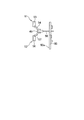
図1に示すように、トルクセンサ100は、入力シャフト3に固定され入力シャフト3と共に回転する磁気発生部20と、出力シャフト4に固定され出力シャフト4と共に回転する回転磁気回路部30と、第1ハウジング11に固定された固定磁気回路部40と、トーションバー5のねじれ変形に伴って磁気発生部20から回転磁気回路部30を通じて固定磁気回路部40に導かれる磁束密度を検出する磁気検出器としての第1磁気センサ48及び第2磁気センサ49(図4参照)と、を備える。トルクセンサ100は、トーションバー5に作用する操舵トルクを第1磁気センサ48及び第2磁気センサ49の出力に基づいて検出する。
上記構成に代えて、磁気発生部20を出力シャフト4と共に回転するように出力シャフト4に固定し、回転磁気回路部30を入力シャフト3と共に回転するように入力シャフト3に固定するようにしてもよい。
磁気発生部20は、入力シャフト3に圧入される環状のバックヨーク21と、バックヨーク21の下端面に結合される環状のリング磁石22と、を備える。
リング磁石22は、入力シャフト3の回転軸方向に磁気を発生する永久磁石である。リング磁石22は、回転軸方向に向けて硬磁性体を着磁することによって形成される多極磁石であり、周方向に等しい幅で形成される12個の磁極を有する。つまり、リング磁石22の上端面及び下端面には、6個のN極と6個のS極が周方向に交互に配設される。リング磁石22の端面に形成される磁極数は、2個以上の範囲で任意に設定される。
バックヨーク21の下端面には、リング磁石22の上端面である上部磁極面が接着剤を介して固定される。バックヨーク24は軟磁性体によって形成されるため、リング磁石22が及ぼす磁界によって磁化され、リング磁石22に吸着する。このように、バックヨーク21とリング磁石22は、接着剤の接着力と磁力とによって結合される。バックヨーク21は、リング磁石22を入力シャフト3に連結する連結部材としての機能と、リング磁石22の隣り合う磁極を結んで磁束を導く継鉄としての機能とを有し、リング磁石22の下端面である下部磁極面に磁力を集中させる。
図1及び図2に示すように、回転磁気回路部30は、リング磁石22から発生する磁束が導かれる第1軟磁性リング31及び第2軟磁性リング32と、出力シャフト4に取り付けられる取付部材33と、取付部材33に第1軟磁性リング31及び第2軟磁性リング32を固定するモールド樹脂34と、を備える。
第1軟磁性リング31は、環状の第1磁路環部31Cと、第1磁路環部31Cから下向きに突出する6個の第1磁路柱部31Bと、各第1磁路柱部31Bの下端からそれぞれ内向きに屈折してリング磁石22の下端面に対峙する第1磁路先端部31Aと、を有する。第2軟磁性リング32は、環状の第2磁路環部32Cと、第2磁路環部32Cから上向きに突出する6個の第2磁路柱部32Bと、各第2磁路柱部32Bの上端からそれぞれ内向きに屈折してリング磁石22の下端面に対峙する第2磁路先端部32Aと、を有する。
第1軟磁性リング31及び第2軟磁性リング32は、プレス加工によって形成される。第1軟磁性リング31及び第2軟磁性リング32は、プレス加工に限らず、鋳造、焼結等によって形成してもよい。
第1磁路先端部31A及び第2磁路先端部32Aは平板状に形成される。第1磁路先端部31Aと第2磁路先端部32Aは、トーションバー5の回転軸と直交する同一平面上に、その回転軸を中心として周方向に交互に等間隔を空けて配置される。また、第1磁路先端部31Aと第2磁路先端部32Aは、トーションバー5にトルクが作用していない中立状態で、トーションバー5の径方向に延びるそれぞれの中心線がリング磁石22のN極とS極の境界を指すように配置される。
第1磁路柱部31Bと第2磁路柱部32Bは、それぞれ平板状に形成され、トーションバー5の回転軸方向に延設される。第1磁路柱部31Bは、所定の間隙を空けてリング磁石22の外周面を囲むように配置される。第1磁路柱部31Bは、リング磁石22の磁束を短絡しないように設けられる。第2磁路柱部32Bは、トーションバー5の回転軸に沿って第1磁路柱部31Bと反対方向に延設される。
第1磁路環部31C及び第2磁路環部32Cは、トーションバー5の回転軸と直交する平面上に配置され、全周がつながった環状に形成される。第1磁路環部31C及び第2磁路環部32Cは、この形状に限られず、部分的にスリットが形成されたC字形状であってもよい。
第1磁路環部31Cはリング磁石22の下端面より上方に配置され、第2磁路環部32Cはリング磁石22より下方に配置される。つまり、リング磁石22は、トーションバー5の回転軸方向について第1磁路環部31Cと第2磁路環部32Cの間に配置される。
図1に示すように、固定磁気回路部40は、第1軟磁性リング31の第1磁路環部31Cの外周に沿って設けられた環状の第1集磁リング41と、第2軟磁性リング32の第2磁路環部32Cの外周に沿って設けられた環状の第2集磁リング42と、第1集磁リング41の外周面に接触して配置された第1集磁ヨーク51(図4及び5参照)と、第2集磁リング42の外周面に接触して配置された第2集磁ヨーク52(図4及び5参照)と、を備える。
第1集磁リング41及び第2集磁リング42は、部分的にスリットが形成されたC字形状であり、第1ハウジング11の内周面にかしめ固定される。第1集磁リング41の内周面は第1軟磁性リング31の第1磁路環部31Cに対峙し、第2集磁リング42の内周面は第2軟磁性リング32の第2磁路環部32Cに対峙する。
このように、第1集磁リング41及び第2集磁リング42は、回転磁気回路部30の外周に配置され、回転磁気回路部30の回転振れや偏心の影響を緩和して第1磁気センサ48及び第2磁気センサ49側へ磁束を導く機能を有する。
なお、第1集磁リング41及び第2集磁リング42は、必須の構成ではなく、廃止してもよい。その場合には、第1集磁ヨーク51は、第1軟磁性リング31の第1磁路環部31Cに沿って配置され、第2集磁ヨーク52は、第2軟磁性リング32の第2磁路環部32Cに沿って配置される。
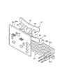
第1集磁ヨーク51及び第2集磁ヨーク52は、第1磁気センサ48及び第2磁気センサ49と共にケース60に設けられて、図3に示す検出部アッシー101を構成する。以下では、図3~9を参照して、検出部アッシー101について詳しく説明する。なお、図9に示す断面図では、基板50とピン70は断面ではなく投影平面を示す。
検出部アッシー101は、トーションバー5のねじれ変形に伴ってリング磁石22から回転磁気回路部30を通じて導かれる磁束密度を検出するものであり、第1ハウジング11に取り付けられる。なお、図1及び7は、検出部アッシー101が取り付けられていない状態を示している。
図3~5に示すように、検出部アッシー101は、磁束密度を検出する第1磁気センサ48及び第2磁気センサ49と、第1磁気センサ48及び第2磁気センサ49が接続される基板50と、固定磁気回路部40の一部を構成し、回転磁気回路部30からの磁束を第1磁気センサ48及び第2磁気センサ49へ導く第1集磁ヨーク51及び第2集磁ヨーク52と、磁気センサ48,49及び基板50を収容し、第1ハウジング11に取り付けられる樹脂製のケース60と、基板50に接続されたピン70を保持するコネクタ80と、を備える。
第1磁気センサ48及び第2磁気センサ49は、図4及び5に示すように、基板50の表面50aから垂直に延びるピン59を介して基板50に接続され、所定の間隔を空けて配置される。
磁気センサ48,49にはホール素子が用いられる。ホール素子は、これを通過する磁束密度に応じた電圧を信号として出力するものである。磁気センサ48,49は、磁束密度の大きさ及び方向に応じた電圧を、基板50を通じて電動パワーステアリング装置1の駆動を制御するEPSコントローラに出力する。
トルクセンサ100に2つの磁気センサ48,49が設けられるのは、両者の出力電圧を比較することによってトルクセンサ100の故障診断をするためである。換言すれば、磁気センサを用いてトルクセンサ100の故障診断を行わない場合には、磁気センサは1つであってもよい。
第1集磁ヨーク51と第2集磁ヨーク52は、互いに同一形状である。図4及び5に示すように、第1集磁ヨーク51は、内周面が第1集磁リング41の外周面に接触するヨーク本体53と、ヨーク本体53から突出して形成される一対の脚部54と、有する。同様に、第2集磁ヨーク52は、内周面が第2集磁リング42の外周面に接触するヨーク本体56と、ヨーク本体56から突出して形成される一対の脚部57と、有する。
第1集磁ヨーク51と第2集磁ヨーク52は、射出成形によって、ケース60と一体成形される。
ヨーク本体53とヨーク本体56は、トーションバー5の軸方向に所定の間隔を空けて互いに平行に配置される。
第1集磁ヨーク51の一対の脚部54及び第2集磁ヨーク52の一対の脚部57は、回転磁気回路部30の周方向に所定の間隔を空けて配置される。脚部54と脚部57は、ヨーク本体53,56の互いに対向する端面から互いに近づく方向へ延びて形成され、脚部54の先端部と脚部57の先端部とは、所定の隙間である磁気ギャップをもって互いに対向する。つまり、第1集磁ヨーク51と第2集磁ヨーク52との間には、周方向に並ぶ一対の磁気ギャップが形成される。一対の磁気ギャップ内には、それぞれ第1磁気センサ48及び第2磁気センサ49が配置される。
集磁ヨーク51,52は、回転磁気回路部30からの磁束を磁気センサ48,49へ集める機能を有する。
ピン70は、基板50上の回路における演算処理結果を、外部に出力するためのものである。図4及び9に示すように、ピン70の一端側は、基板50の表面50aに接続され、ピン70の他端側は、コネクタ80に保持される。ピン70は、射出成形によって、ケース60及びコネクタ80と一体成形される。
次に、図3~9を参照して、ケース60及びコネクタ80について説明する。
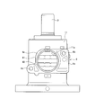
ケース60は、第1ハウジング11に形成された開口部11a(図1及び7参照)に嵌合する嵌合部61と、第1ハウジング11から露出して配置され、内部に基板50が収容される基板収容部62と、基板収容部62の開口部62aを封止するカバー63と、第1ハウジング11に締結される鍔部としてのフランジ部64と、を備える。
コネクタ80は、基板50とEPSコントローラとを電気的に接続するためのものであり、ケース60と一体に形成される。
ケース60とコネクタ80は樹脂製であるが、樹脂製に限定されることはなく、非磁性材で形成されていればよい。
図7に示すように、第1ハウジング11の外周面には、検出部アッシー101が取り付けられる取付ベース6が形成される。取付ベース6には、ケース60のフランジ部64が接触して締結される平面状の取付面6aと、取付面6aに円形に開口する開口部11aと、が形成される。
開口部11aは、取付ベース6及び第1ハウジング11を貫通して形成される。取付ベース6に検出部アッシー101が取り付けられていない状態(図1及び7に示す状態)では、第1ハウジング11内に設けられた集磁リング41,42が開口部11aに臨む。
嵌合部61は、円柱状に形成され、外周面が開口部11aの内周面に嵌合する(図9参照)。嵌合部61が開口部11aに嵌合した状態では、嵌合部61の中心軸は、トーションバー5の径方向に延びる。開口部11aの内周面には、嵌合部61の外周面との間をシールするOリング18(図1及び9参照)が設けられる。これにより、開口部11aと嵌合部61の間を通じて外部から第1ハウジング11内へ泥水等が侵入するのが防止される。
嵌合部61における第1ハウジング11内に臨む面、つまり嵌合部61の先端面61aには、集磁ヨーク51,52のヨーク本体53,56の内周面が露出して配置される(図9参照)。したがって、嵌合部61が開口部11aに嵌合した状態では、ヨーク本体53,56が第1ハウジング11内に配置された集磁リング41,42の外周面に接触して、集磁リング41、42と集磁ヨーク51,52の間の磁路が構成される。
基板収容部62は、基板50が収容される空間62bを内部に有する。基板50は、開口部62aを通じて空間62bに収容される。基板50は、熱かしめと接着剤によって空間62b内に固定される。基板収容部62の外形は、基板50の形状に倣って矩形に形成される。
フランジ部64は、嵌合部61の外周面に対して垂直方向に延設され、取付ベース6の取付面6aに接触する接触面64aを有する。フランジ部64には、締結用のボルト65が挿通する一対のボルト挿通孔64bが形成される。一対のボルト挿通孔64bは、嵌合部61の中心軸を中心として対称位置に形成される。取付ベース6には、一対のボルト挿通孔64bに対応する位置にボルト65がねじ込まれるねじ穴6b(図7参照)が形成される。
コネクタ80は、底部81と円筒部82とを有する有底筒状に形成される。円筒部82は、軸方向の長さが直径と比較して長い。ピン70の一部は、底部81にて保持される共に、円筒部82内を円筒部82の軸方向に延在する。コネクタ80はオス形状のコネクタであり、メス形状の相手側コネクタと接続される。コネクタ80と相手側コネクタが接続されることにより、基板50とEPSコントローラとが電気的に接続される。
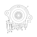
図9に示すように、コネクタ80は、その中心軸C1が嵌合部61の中心軸C2からオフセットしてケース60の側部に一体に形成される。つまり、コネクタ80の中心軸C1と嵌合部61の中心軸C2は、互いにずれて形成される。具体的には、コネクタ80は、中心軸C1が嵌合部61の中心軸C2からトーションバー5の径方向にオフセットして形成される。このように、コネクタ80の中心軸C1は嵌合部61の中心軸C2からオフセットしており、コネクタ80の中心軸C1と嵌合部61の中心軸C2とは平行に延びる。したがって、中心軸C1が嵌合部61の中心軸C2と垂直な向きにコネクタ80がケース60と一体に形成される形状と比較して、検出部アッシー101は幅寸法が小さくコンパクトとなる。つまり、ケース60の幅方向(嵌合部61の中心軸C2に垂直な方向)において、コネクタ80はケース60から大きく張り出すことなく形成される。
コネクタ80の中心軸C1は、嵌合部61の中心軸C2に対して完全に平行である必要はなく、中心軸C2に対して傾いた状態でオフセットしていてもよい。ただ、中心軸C1が中心軸C2から平行にオフセットする形態が、検出部アッシー101をコンパクトに構成することができるため、好ましい。
さらに、コネクタ80は、相手側コネクタと接続される接続口80aが第1ハウジング11の外周面と対向しない向きに、ケース60と一体に形成されると共に、接続口80aと反対側の端面である底面80bがフランジ部64の接触面64aから第1ハウジング11側にオフセットして形成される。このように、フランジ部64の接触面64aとコネクタ80の底面80bとは、同一面上には形成されずに、段状に形成される。
取付ベース6におけるコネクタ80の底面80bに対向する部分には、図7に示すように、部分的に切り欠かれた切欠部6cが形成される。したがって、フランジ部64の接触面64aとコネクタ80の底面80bとが段状に形成されていても、コネクタ80の底面80bが取付ベース6に干渉することはない。
コネクタ80の底面80bがフランジ部64の接触面64aから第1ハウジング11側にオフセットすることによって、コネクタ80の円筒部82は取付ベース6の側面6d(図9参照)に沿って配置され、かつコネクタ80の底面80bは第1ハウジング11の外周面に近接して配置される。フランジ部64の接触面64aに対するコネクタ80の底面80bのオフセット量(ずれ量)は、底面80bが第1ハウジング11の外周面に干渉しない位置まで増やすことができる。
このように、コネクタ80の底面80bがフランジ部64の接触面64aから第1ハウジング11側にオフセットしているため、コネクタ80を第1ハウジング11に極力近づけて配置させることができる。したがって、ケース60の背面側へのコネクタ80の張り出しを抑えることができるため、検出部アッシー101はコンパクトに第1ハウジング11に取り付けられる。
コネクタ80の底面80bをフランジ部64の接触面64aから第1ハウジング11側にオフセットさせることが可能になったのは、ピン70の形状による。以下では、ピン70の形状について説明する。
図4及び9に示すように、ピン70は、基板50と平行に形成された第1平行部70aと、基板50と垂直に形成され、第1ハウジング11側へ延びる第1垂直部70bと、基板50と平行に形成され、基板50から遠ざかる方向へ延びる第2平行部70cと、基板50と垂直に形成され、第1ハウジング11から遠ざかる方向へ延びる第2垂直部70dと、を有する。このように、ピン70の一部は、第1ハウジング11側に折れ曲がる屈曲部を有する。
第2垂直部70dは、コネクタ80の底部81から突出して形成され、接続口80aに向かって円筒部82内を延在する。
第2平行部70cは、フランジ部64の接触面64aよりも第1ハウジング11側に位置する。つまり、ピン70の一部は、フランジ部64の接触面64aよりも第1ハウジング11側に位置する。このように、ピン70の一部がフランジ部64の接触面64aよりも第1ハウジング11側に位置するため、コネクタ80の底面80bをフランジ部64の接触面64aから第1ハウジング11側にオフセットさせることが可能となる。
以上のように構成される検出部アッシー101の第1ハウジング11への取り付けは、ケース60の嵌合部61を取付ベース6の開口部11aに嵌合させ、フランジ部64の接触面64aを取付ベース6の取付面6aに面接触させた状態で、ボルト65をボルト挿通孔64bとねじ穴6bに亘って締結することによって行われる。
ここで、一対のボルト挿通孔64bは、嵌合部61の中心軸C2を中心として対称位置に形成されるため、検出部アッシー101を上下反対にしても(180度回転させても)、第1ハウジング11へ取り付けることができる。この場合には、コネクタ80の位置が嵌合部61を挟んで逆側となる。このように、検出部アッシー101の取り付け方向によってコネクタ80の位置を変更することができるため、車両側の部品のレイアウトに応じてコネクタ80の位置を選択することができる。ただ、この場合には、図6及び7では、取付ベース6の切欠部6cが1つしか形成されていないが、開口部11aの中心軸を中心として対称位置に一対の切欠部6cを形成する必要がある。
なお、切欠部6cが取付ベース6に1つしか形成されない場合には、検出部アッシー101の取り付け方向は必然的に決まるため、切欠部6cを検出部アッシー101の誤組み付け防止用として用いることができる。つまり、車両側の部品のレイアウトによってコネクタ80の位置が制約を受ける場合には、コネクタ80の位置に合わせて切欠部6cを1つだけ形成すれば、検出部アッシー101の誤組み付けを防止することができる。
以下に、トルクセンサ100によるトーションバー5に作用する操舵トルクの検出方法について説明する。
トーションバー5にトルクが作用しない中立状態では、第1軟磁性リング31の第1磁路先端部31Aと第2軟磁性リング32の第2磁路先端部32Aとは、それぞれリング磁石22のN極及びS極に同一の面積で対峙して両者を磁気短絡する。そのため、磁束は回転磁気回路部30と固定磁気回路部40に導かれない。
運転者によるステアリングホイールの操作によってトーションバー5に特定の方向のトルクが作用した場合には、このトルクの方向に応じてトーションバー5はねじれ変形する。トーションバー5がねじれ変形すると、第1磁路先端部31AがS極よりN極に大きな面積を持って対峙する一方、第2磁路先端部32AがN極よりS極に大きな面積を持って対峙する。リング磁石22からの磁束は回転磁気回路部30を通じて固定磁気回路部40に導かれる。具体的には、N極から第1軟磁性リング31、第1集磁リング41、第1集磁ヨーク51、第2集磁ヨーク52、第2集磁リング42、第2軟磁性リング32を経由してS極に向かう経路である。第1集磁ヨーク51と第2集磁ヨーク52の間の磁気ギャップに設置された第1磁気センサ48及び第2磁気センサ49は、磁束の大きさ及び方向に応じた電圧値を出力する。
一方、運転者によるステアリングホイールの操作によってトーションバー5に上記とは逆方向のトルクが作用した場合には、このトルクの方向に応じてトーションバー5が逆方向にねじれ変形する。トーションバー5がねじれ変形すると、第1磁路先端部31AがN極よりS極に大きな面積を持って対峙する一方、第2磁路先端部32AがS極よりN極に大きな面積を持って対峙する。リング磁石22からの磁束は、回転磁気回路部30を通じて固定磁気回路部40に導かれるが、上記とは逆の経路となる。具体的には、N極から第2軟磁性リング32、第2集磁リング42、第2集磁ヨーク52、第1集磁ヨーク51、第1集磁リング41、第1軟磁性リング31を経由してS極に向かう経路である。第1集磁ヨーク51と第2集磁ヨーク52の間の磁気ギャップに設置された第1磁気センサ48及び第2磁気センサ49は、磁束の大きさ及び方向に応じた電圧値を出力する。
運転者の操作によりステアリングホイールに入力される操舵トルクが大きい程、トーションバー5のねじれ変形量が多くなるため、第1磁路先端部31Aがリング磁石22のN極とS極に対峙する面積差、及び第2磁路先端部32Aがリング磁石22のN極とS極に対峙する面積差が大きくなり、磁気ギャップに誘導される磁束が大きくなる。これに応じて、第1磁気センサ48及び第2磁気センサ49の出力電圧も増大する。したがって、リング磁石22の磁極数を増やすことにより、第1磁気センサ48及び第2磁気センサ49に導かれる磁束密度を高めることができる。
以上の実施形態によれば、以下に示す効果を奏する。
コネクタ80は、その中心軸C1が嵌合部61の中心軸C2からトーションバー6の径方向にオフセットして形成されると共に、底面80bがフランジ部64の接触面64aから第1ハウジング11側にオフセットして形成される。コネクタ80がこのような形態でケース60と一体に形成されることによって、コネクタ80は、ケース60の幅方向(嵌合部61の中心軸C2に垂直な方向)及びケース60の背面側(嵌合部61の中心軸C2方向であって反第1ハウジング11側)へ大きく張り出すことなく形成される。したがって、検出部アッシー101はコンパクトに第1ハウジング11に取り付けられる。よって、電動パワーステアリング装置1を車両に取り付ける際に、検出部アッシー101が車両側の部品と干渉することが防止され、車両への電動パワーステアリング装置1の搭載性が向上する。
以下、本発明の実施形態の構成、作用、及び効果をまとめて説明する。
ハウジング11,12内に回転自在に支持された入力シャフト(第1シャフト)3と出力シャフト(第2シャフト)4とを連結するトーションバー5に作用するトルクを検出するトルクセンサ100は、入力シャフト3と共に回転する磁気発生部20と、出力シャフト4と共に回転する回転磁気回路部30と、トーションバー5のねじれ変形に伴って磁気発生部20から回転磁気回路部30を通じて導かれる磁束密度を検出する検出部アッシー101と、を備え、検出部アッシー101は、磁束密度を検出する磁気センサ(磁気検出器)48,49と、磁気センサ48,49が接続される基板50と、磁気センサ48,49及び基板50を収容し、ハウジング11に取り付けられる非磁性のケース60と、基板50に接続されたピン70を保持し、ケース60と一体に形成されたコネクタ80と、を有し、ケース60は、ハウジング11に形成された開口部11aに嵌合され、中心軸C2がトーションバー5の径方向に延びる嵌合部61と、嵌合部61の外周面に対して垂直方向に延設され、ハウジング11に締結されるフランジ部(鍔部)64と、を有し、コネクタ80は、その中心軸C1が嵌合部61の中心軸C2からトーションバー5の径方向にオフセットして形成されると共に、相手側コネクタと接続される接続口80aと反対側の底面(端面)80bがフランジ部64におけるハウジング11との接触面64aからハウジング11側にオフセットして形成される。
この構成では、コネクタ80がケース60から大きく張り出すことなく形成されるため、検出部アッシー101はコンパクトにハウジング11に取り付けられる。よって、車両への電動パワーステアリング装置1の搭載性を向上させることができる。
また、コネクタ80は、その中心軸C1が嵌合部61の中心軸C2と平行に形成される。
この構成では、検出部アッシー101は、よりコンパクトにハウジング11に取り付けられる。
また、ピン70の一部は、フランジ部64の接触面64aよりもハウジング11側に位置する。
また、ピン70は、基板50と平行に形成された第1平行部70aと、基板50と垂直に形成されハウジング11側へ延びる第1垂直部70bと、基板50と平行に形成され基板50から遠ざかる方向へ延びる第2平行部70cと、基板50と垂直に形成されハウジング11から遠ざかる方向へ延びる第2垂直部70cと、を有し、第2平行部70cは、フランジ部64の接触面64aよりもハウジング11側に位置する。
これらの構成では、コネクタ80をハウジング11に近づけて配置させることができる。したがって、ケース60の背面側へのコネクタ80の張り出しを抑えることができるため、検出部アッシー101はコンパクトにハウジング11に取り付けられる。
以上、本発明の実施形態について説明したが、上記実施形態は本発明の適用例の一部を示したに過ぎず、本発明の技術的範囲を上記実施形態の具体的構成に限定する趣旨ではない。
本願は2016年10月5日に日本国特許庁に出願された特願2016-197317に基づく優先権を主張し、この出願の全ての内容は参照により本明細書に組み込まれる。
Claims (4)
- ハウジング内に回転自在に支持された第1シャフトと第2シャフトとを連結するトーションバーに作用するトルクを検出するトルクセンサであって、
前記第1シャフトと共に回転する磁気発生部と、
前記第2シャフトと共に回転する回転磁気回路部と、
前記トーションバーのねじれ変形に伴って前記磁気発生部から前記回転磁気回路部を通じて導かれる磁束密度を検出する検出部アッシーと、を備え、
前記検出部アッシーは、
磁束密度を検出する磁気検出器と、
前記磁気検出器が接続される基板と、
前記磁気検出器及び前記基板を収容し、前記ハウジングに取り付けられる非磁性のケースと、
前記基板に接続されたピンを保持し、前記ケースと一体に形成されたコネクタと、を有し、
前記ケースは、
前記ハウジングに形成された開口部に嵌合され、中心軸が前記トーションバーの径方向に延びる嵌合部と、
前記嵌合部の外周面に対して垂直方向に延設され、前記ハウジングに締結される鍔部と、を有し、
前記コネクタは、その中心軸が前記嵌合部の前記中心軸から前記トーションバーの径方向にオフセットして形成されると共に、相手側コネクタと接続される接続口と反対側の端面が前記鍔部における前記ハウジングとの接触面から前記ハウジング側にオフセットして形成されるトルクセンサ。 - 請求項1に記載のトルクセンサであって、
前記コネクタは、その中心軸が前記嵌合部の前記中心軸と平行に形成されるトルクセンサ。 - 請求項1に記載のトルクセンサであって、
前記ピンの一部は、前記鍔部の前記接触面よりも前記ハウジング側に位置するトルクセンサ。 - 請求項3に記載のトルクセンサであって、
前記ピンは、
前記基板と平行に形成された第1平行部と、
前記基板と垂直に形成され、前記ハウジング側へ延びる第1垂直部と、
前記基板と平行に形成され、前記基板から遠ざかる方向へ延びる第2平行部と、
前記基板と垂直に形成され、前記ハウジングから遠ざかる方向へ延びる第2垂直部と、を有し、
前記第2平行部は、前記鍔部の前記接触面よりも前記ハウジング側に位置するトルクセンサ。
Priority Applications (3)
| Application Number | Priority Date | Filing Date | Title |
|---|---|---|---|
| CN201780054781.4A CN109690271A (zh) | 2016-10-05 | 2017-10-02 | 扭矩传感器 |
| US16/333,225 US20190226925A1 (en) | 2016-10-05 | 2017-10-02 | Torque sensor |
| DE112017005055.3T DE112017005055T5 (de) | 2016-10-05 | 2017-10-02 | Drehmomentsensor |
Applications Claiming Priority (2)
| Application Number | Priority Date | Filing Date | Title |
|---|---|---|---|
| JP2016-197317 | 2016-10-05 | ||
| JP2016197317A JP6726593B2 (ja) | 2016-10-05 | 2016-10-05 | トルクセンサ |
Publications (1)
| Publication Number | Publication Date |
|---|---|
| WO2018066529A1 true WO2018066529A1 (ja) | 2018-04-12 |
Family
ID=61831105
Family Applications (1)
| Application Number | Title | Priority Date | Filing Date |
|---|---|---|---|
| PCT/JP2017/035883 Ceased WO2018066529A1 (ja) | 2016-10-05 | 2017-10-02 | トルクセンサ |
Country Status (5)
| Country | Link |
|---|---|
| US (1) | US20190226925A1 (ja) |
| JP (1) | JP6726593B2 (ja) |
| CN (1) | CN109690271A (ja) |
| DE (1) | DE112017005055T5 (ja) |
| WO (1) | WO2018066529A1 (ja) |
Cited By (2)
| Publication number | Priority date | Publication date | Assignee | Title |
|---|---|---|---|---|
| EP3816599A4 (en) * | 2018-06-28 | 2021-12-29 | Denso Corporation | Magnetic detection module, detection device, case assembly, and production method for magnetic detection module |
| EP4109064A1 (en) | 2018-06-28 | 2022-12-28 | Denso Corporation | Magnetic detection module, detection device, case assembly, and production method for magnetic detection module |
Families Citing this family (4)
| Publication number | Priority date | Publication date | Assignee | Title |
|---|---|---|---|---|
| JP7257635B2 (ja) * | 2019-08-23 | 2023-04-14 | 多摩川精機株式会社 | トルクセンサ用ホールicの出力コネクタ構造 |
| DE102020209463A1 (de) | 2020-07-28 | 2022-02-03 | Zf Friedrichshafen Ag | Lenksystem und Sensormodul für ein Lenksystem |
| CN112039282A (zh) * | 2020-08-28 | 2020-12-04 | 北京理工大学重庆创新中心 | 一种集成式油泵 |
| US20250189389A1 (en) * | 2022-03-22 | 2025-06-12 | Jtekt Corporation | Sensor device |
Citations (4)
| Publication number | Priority date | Publication date | Assignee | Title |
|---|---|---|---|---|
| US20040099064A1 (en) * | 2002-11-22 | 2004-05-27 | Viola Jeffrey Louis | Magnetoelastic torque sensor assembly |
| JP2011257225A (ja) * | 2010-06-08 | 2011-12-22 | Kayaba Ind Co Ltd | トルクセンサ |
| JP2012073212A (ja) * | 2010-09-27 | 2012-04-12 | Bourns Inc | 3部分のトルクセンサ組立体 |
| JP2013531224A (ja) * | 2010-05-14 | 2013-08-01 | ティーアールダブリュー・オートモーティブ・ユーエス・エルエルシー | トルク・センサ組立体およびその製作方法 |
Family Cites Families (5)
| Publication number | Priority date | Publication date | Assignee | Title |
|---|---|---|---|---|
| FR2750180B1 (fr) * | 1996-06-21 | 1998-07-31 | Roulements Soc Nouvelle | Arbre tournant incorporant un dispositif de mesure de couple de torsion |
| JP2006038767A (ja) * | 2004-07-29 | 2006-02-09 | Favess Co Ltd | トルク検出装置 |
| JP4871014B2 (ja) * | 2006-04-24 | 2012-02-08 | カヤバ工業株式会社 | トルクセンサ |
| JP5513902B2 (ja) * | 2010-01-12 | 2014-06-04 | カヤバ工業株式会社 | トルクセンサ |
| JP2016197317A (ja) | 2015-04-03 | 2016-11-24 | グローリー株式会社 | 紙幣計数装置 |
-
2016
- 2016-10-05 JP JP2016197317A patent/JP6726593B2/ja active Active
-
2017
- 2017-10-02 DE DE112017005055.3T patent/DE112017005055T5/de not_active Withdrawn
- 2017-10-02 US US16/333,225 patent/US20190226925A1/en not_active Abandoned
- 2017-10-02 WO PCT/JP2017/035883 patent/WO2018066529A1/ja not_active Ceased
- 2017-10-02 CN CN201780054781.4A patent/CN109690271A/zh active Pending
Patent Citations (4)
| Publication number | Priority date | Publication date | Assignee | Title |
|---|---|---|---|---|
| US20040099064A1 (en) * | 2002-11-22 | 2004-05-27 | Viola Jeffrey Louis | Magnetoelastic torque sensor assembly |
| JP2013531224A (ja) * | 2010-05-14 | 2013-08-01 | ティーアールダブリュー・オートモーティブ・ユーエス・エルエルシー | トルク・センサ組立体およびその製作方法 |
| JP2011257225A (ja) * | 2010-06-08 | 2011-12-22 | Kayaba Ind Co Ltd | トルクセンサ |
| JP2012073212A (ja) * | 2010-09-27 | 2012-04-12 | Bourns Inc | 3部分のトルクセンサ組立体 |
Cited By (2)
| Publication number | Priority date | Publication date | Assignee | Title |
|---|---|---|---|---|
| EP3816599A4 (en) * | 2018-06-28 | 2021-12-29 | Denso Corporation | Magnetic detection module, detection device, case assembly, and production method for magnetic detection module |
| EP4109064A1 (en) | 2018-06-28 | 2022-12-28 | Denso Corporation | Magnetic detection module, detection device, case assembly, and production method for magnetic detection module |
Also Published As
| Publication number | Publication date |
|---|---|
| US20190226925A1 (en) | 2019-07-25 |
| CN109690271A (zh) | 2019-04-26 |
| JP6726593B2 (ja) | 2020-07-22 |
| JP2018059805A (ja) | 2018-04-12 |
| DE112017005055T5 (de) | 2019-06-19 |
Similar Documents
| Publication | Publication Date | Title |
|---|---|---|
| WO2018066529A1 (ja) | トルクセンサ | |
| US9821846B2 (en) | Device with a torque sensor device and a steering angle sensor device for a motor vehicle, motor vehicle and method for operating the device | |
| EP3470808B1 (en) | Torque sensor | |
| JP7103498B2 (ja) | 検出装置 | |
| CN111746640B (zh) | 传感器装置 | |
| WO2013140864A1 (ja) | トルクセンサ | |
| US11579211B2 (en) | Detection device | |
| JP6691071B2 (ja) | トルクセンサ | |
| EP4394340B1 (en) | Torque detection device | |
| JP2014149180A (ja) | トルクセンサ | |
| JP2008241564A (ja) | 舵角検出装置及びステアリング装置 | |
| JP5852484B2 (ja) | トルクセンサ | |
| US9945742B2 (en) | Torque sensor and electric power steering apparatus | |
| JP7596104B2 (ja) | トルクセンサ | |
| JP2018059741A (ja) | トルクセンサの製造方法 | |
| KR101949432B1 (ko) | 토크 센서 장치 | |
| JP2018059740A (ja) | トルクセンサ | |
| JP7322811B2 (ja) | 磁気センサ、トルク検出装置、ステアリング装置 | |
| JP7378883B2 (ja) | トルクセンサ | |
| JP2021173634A (ja) | トルクセンサ | |
| JP2025036808A (ja) | 回転検出装置およびパワーステアリング装置 | |
| WO2018173571A1 (ja) | パワーステアリング装置 | |
| KR20160029990A (ko) | 토크 센서 장치 |
Legal Events
| Date | Code | Title | Description |
|---|---|---|---|
| 121 | Ep: the epo has been informed by wipo that ep was designated in this application |
Ref document number: 17858367 Country of ref document: EP Kind code of ref document: A1 |
|
| 122 | Ep: pct application non-entry in european phase |
Ref document number: 17858367 Country of ref document: EP Kind code of ref document: A1 |