WO2018066331A1 - 浮上分離装置 - Google Patents
浮上分離装置 Download PDFInfo
- Publication number
- WO2018066331A1 WO2018066331A1 PCT/JP2017/033059 JP2017033059W WO2018066331A1 WO 2018066331 A1 WO2018066331 A1 WO 2018066331A1 JP 2017033059 W JP2017033059 W JP 2017033059W WO 2018066331 A1 WO2018066331 A1 WO 2018066331A1
- Authority
- WO
- WIPO (PCT)
- Prior art keywords
- tank
- pump
- water
- floating
- stirring
- Prior art date
- Legal status (The legal status is an assumption and is not a legal conclusion. Google has not performed a legal analysis and makes no representation as to the accuracy of the status listed.)
- Ceased
Links
Images



Classifications
-
- B—PERFORMING OPERATIONS; TRANSPORTING
- B03—SEPARATION OF SOLID MATERIALS USING LIQUIDS OR USING PNEUMATIC TABLES OR JIGS; MAGNETIC OR ELECTROSTATIC SEPARATION OF SOLID MATERIALS FROM SOLID MATERIALS OR FLUIDS; SEPARATION BY HIGH-VOLTAGE ELECTRIC FIELDS
- B03D—FLOTATION; DIFFERENTIAL SEDIMENTATION
- B03D1/00—Flotation
- B03D1/02—Froth-flotation processes
- B03D1/028—Control and monitoring of flotation processes; computer models therefor
-
- B—PERFORMING OPERATIONS; TRANSPORTING
- B03—SEPARATION OF SOLID MATERIALS USING LIQUIDS OR USING PNEUMATIC TABLES OR JIGS; MAGNETIC OR ELECTROSTATIC SEPARATION OF SOLID MATERIALS FROM SOLID MATERIALS OR FLUIDS; SEPARATION BY HIGH-VOLTAGE ELECTRIC FIELDS
- B03D—FLOTATION; DIFFERENTIAL SEDIMENTATION
- B03D1/00—Flotation
- B03D1/14—Flotation machines
- B03D1/1443—Feed or discharge mechanisms for flotation tanks
- B03D1/1462—Discharge mechanisms for the froth
-
- B—PERFORMING OPERATIONS; TRANSPORTING
- B03—SEPARATION OF SOLID MATERIALS USING LIQUIDS OR USING PNEUMATIC TABLES OR JIGS; MAGNETIC OR ELECTROSTATIC SEPARATION OF SOLID MATERIALS FROM SOLID MATERIALS OR FLUIDS; SEPARATION BY HIGH-VOLTAGE ELECTRIC FIELDS
- B03D—FLOTATION; DIFFERENTIAL SEDIMENTATION
- B03D1/00—Flotation
- B03D1/14—Flotation machines
- B03D1/16—Flotation machines with impellers; Subaeration machines
- B03D1/20—Flotation machines with impellers; Subaeration machines with internal air pumps
-
- C—CHEMISTRY; METALLURGY
- C02—TREATMENT OF WATER, WASTE WATER, SEWAGE, OR SLUDGE
- C02F—TREATMENT OF WATER, WASTE WATER, SEWAGE, OR SLUDGE
- C02F1/00—Treatment of water, waste water, or sewage
- C02F1/24—Treatment of water, waste water, or sewage by flotation
-
- C—CHEMISTRY; METALLURGY
- C02—TREATMENT OF WATER, WASTE WATER, SEWAGE, OR SLUDGE
- C02F—TREATMENT OF WATER, WASTE WATER, SEWAGE, OR SLUDGE
- C02F1/00—Treatment of water, waste water, or sewage
- C02F1/40—Devices for separating or removing fatty or oily substances or similar floating material
-
- C—CHEMISTRY; METALLURGY
- C02—TREATMENT OF WATER, WASTE WATER, SEWAGE, OR SLUDGE
- C02F—TREATMENT OF WATER, WASTE WATER, SEWAGE, OR SLUDGE
- C02F1/00—Treatment of water, waste water, or sewage
- C02F1/52—Treatment of water, waste water, or sewage by flocculation or precipitation of suspended impurities
-
- B—PERFORMING OPERATIONS; TRANSPORTING
- B03—SEPARATION OF SOLID MATERIALS USING LIQUIDS OR USING PNEUMATIC TABLES OR JIGS; MAGNETIC OR ELECTROSTATIC SEPARATION OF SOLID MATERIALS FROM SOLID MATERIALS OR FLUIDS; SEPARATION BY HIGH-VOLTAGE ELECTRIC FIELDS
- B03D—FLOTATION; DIFFERENTIAL SEDIMENTATION
- B03D2201/00—Specified effects produced by the flotation agents
- B03D2201/002—Coagulants and Flocculants
-
- B—PERFORMING OPERATIONS; TRANSPORTING
- B03—SEPARATION OF SOLID MATERIALS USING LIQUIDS OR USING PNEUMATIC TABLES OR JIGS; MAGNETIC OR ELECTROSTATIC SEPARATION OF SOLID MATERIALS FROM SOLID MATERIALS OR FLUIDS; SEPARATION BY HIGH-VOLTAGE ELECTRIC FIELDS
- B03D—FLOTATION; DIFFERENTIAL SEDIMENTATION
- B03D2203/00—Specified materials treated by the flotation agents; Specified applications
- B03D2203/008—Water purification, e.g. for process water recycling
-
- C—CHEMISTRY; METALLURGY
- C02—TREATMENT OF WATER, WASTE WATER, SEWAGE, OR SLUDGE
- C02F—TREATMENT OF WATER, WASTE WATER, SEWAGE, OR SLUDGE
- C02F2103/00—Nature of the water, waste water, sewage or sludge to be treated
- C02F2103/14—Paint wastes
-
- Y—GENERAL TAGGING OF NEW TECHNOLOGICAL DEVELOPMENTS; GENERAL TAGGING OF CROSS-SECTIONAL TECHNOLOGIES SPANNING OVER SEVERAL SECTIONS OF THE IPC; TECHNICAL SUBJECTS COVERED BY FORMER USPC CROSS-REFERENCE ART COLLECTIONS [XRACs] AND DIGESTS
- Y02—TECHNOLOGIES OR APPLICATIONS FOR MITIGATION OR ADAPTATION AGAINST CLIMATE CHANGE
- Y02P—CLIMATE CHANGE MITIGATION TECHNOLOGIES IN THE PRODUCTION OR PROCESSING OF GOODS
- Y02P70/00—Climate change mitigation technologies in the production process for final industrial or consumer products
- Y02P70/10—Greenhouse gas [GHG] capture, material saving, heat recovery or other energy efficient measures, e.g. motor control, characterised by manufacturing processes, e.g. for rolling metal or metal working
Definitions
- the present invention relates to a flotation separation apparatus for flotation separation processing by adding a flocculant to raw water. More specifically, the present invention relates to a flotation separation apparatus suitable for use in flotation-separating paint soot contained in a coating waste liquid.
- a spray coating method in which paint is sprayed in a coating booth is often used.
- the amount of paint that contributes to actual painting is about 30% of the sprayed paint, and the remaining 70% is surplus paint.
- These surplus paints are generally captured by a water curtain or the like provided in the painting booth and collected in circulating water. Then, the circulating water containing the surplus paint component is collected in the circulating water pit, and then the circulating water and the paint component are separated according to a predetermined method.
- Patent Document 1 a powder flocculant is added to the circulating water containing the paint component and stirred, the circulating water and the paint component are floated and separated, and the floated paint component is discharged by a scraping device. A separation device is described.
- the paint soot that is levitated and separated will have a higher moisture content and a lower SS recovery rate. Along with this, the concentration of the treated water SS becomes high, causing the above-mentioned pressurized water pump to be consumed, and the treatment performance of the entire apparatus is also lowered.
- a powdery flocculant is used in the apparatus of Patent Document 1.
- the powdery flocculant has disadvantages such as occurrence of defective cutting in the apparatus and easy scattering.
- the present invention is provided in a stirring tank into which raw water and a flocculant are introduced, and in the stirring tank.
- the raw water to which the flocculant is added is sucked together with air from a suction port and discharged to the lower part of the stirring tank.
- An air entrainment by the pump in a levitation separation apparatus comprising: a pump that flocculates, a levitation tank into which the condensed water in the agitation tank flows over the overflow weir, and a scraper that scrapes the levitated matter from the levitation tank. It is an object of the present invention to provide a flotation separation device capable of adjusting the amount.
- stir tank into which raw water and flocculant are introduced means that the raw water and the flocculant are separately introduced into the stirring tank, and the raw water to which the flocculant has been added in advance is added to the stirring tank. Including the case of introduction.
- the flotation separation apparatus of the present invention is provided in a stirring tank into which raw water and a flocculant are introduced, and in the stirring tank by sucking raw water to which the flocculant has been added together with air from a suction port.
- a floating separation apparatus having a pump that discharges to a lower part of the tank, a floating tank in which the condensed water in the stirring tank flows over the overflow weir, and a scraper that scrapes floating matter from the floating tank. At least one of the flow weir and the pump is vertically movable.
- the pump is a stirring pump equipped with an impeller.
- the overflow weir has a weir plate that is inclined toward the stirring tank from the bottom to the top.
- the scraper scrapes the levitated material from the entire surface of the water surface of the levitating tank.
- the inside of the levitation tank is partitioned into a plurality of small levitation tanks by a first partition plate, and the floating material in each small levitation tank is scraped out by a common scraper.
- the inside of the stirring tank is partitioned into a plurality of small stirring tanks by a second partition plate, and one small floating tank is disposed adjacent to one small stirring tank.
- the overflow weir is vertically movable, and the distance between the water surface in the stirring tank and the pump suction port is adjusted by adjusting the vertical height of at least one of the overflow weir and the pump. Can be adjusted. Thereby, the air entrainment amount by a pump can be adjusted.
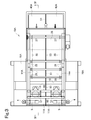
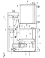
- FIG. 4 is a sectional view taken along line IV-IV in FIG. 3. It is a top view of the levitation separator concerning another embodiment.
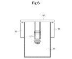
- FIG. 6 is a sectional view taken along line VI-VI in FIG. 5.
- FIG. 1 shows a spray paint wastewater treatment apparatus equipped with a flotation separation apparatus according to a first embodiment.
- the paint wastewater containing the paint component is sent from the raw water tank (Kashiike) 1 to the floating separation device 10 via the float pump 2, the hose 3, the valve 4 and the pipe 5 and is subjected to the floating separation treatment.
- the floating object is scraped off by a scraper and is dropped into the collection tank 40.
- the levitation separation apparatus 10 includes a stirring tank 11, a stirring pump 12 installed in the stirring tank 11, a floating tank 14 into which condensed water flows from the stirring tank 11 through an overflow weir 13, Scraper 15 as a scraping device that scrapes off the floating material of the water, a treated water tank 16 into which treated water in the floating tank 14 flows, a pump 17 and a hose for returning treated water in the treated water tank 16 to the raw water tank 1 18 etc.
- a cross beam (not shown in FIGS. 1 and 2; see FIGS. 3 to 6) is provided across the upper side of the agitation tank 11, and the agitation pump 12 is held suspended from the cross beam.
- the agitation pump 12 is configured to suck air and water in the agitation tank 11 and discharge water mixed with bubbles to the lower part of the agitation tank 11.
- the agitation pump 12 is preferably equipped with an impeller, a two-pole motor with a high rotational speed, and a filth submersible pump with a large foreign substance passage diameter, and installed by suspending. It has a controller for inverter control of the motor for adjusting the stirring intensity and suction amount.
- the upper limit frequency is 55 Hz or less so as not to exceed the rated current value of the pump motor.
- a thermal protector that is installed in the submersible pump as it is removed because it may adversely affect the inverter body during automatic recovery. It is preferable to cut the legs of the submersible pump because they interfere with the intake of the levitating rod.
- the tank body 20 of the stirring tank 11, the levitation tank 14, and the treated water tank 16 is integrally configured and placed on the base 21.
- a first partition plate 22 is erected so as to partition the agitation tank 11 and the levitation tank 14, and an overflow weir 13 is installed above the first partition plate 22.
- the overflow weir 13 is constituted by an overflow plate 13A shown in FIG.
- the overflow plate 13A has a rectangular shape (in this embodiment, a rectangle), and is provided with elongated holes 13a extending in the vertical direction at both left and right ends. 13 A of overflow plates are arrange
- the overflow plate 13A is attached to the first partition plate 22 by a fixing member 23 such as a bolt and a nut inserted into the long hole 13a.
- a fixing member 23 such as a bolt and a nut inserted into the long hole 13a.
- the upper part of the 1st partition plate 22 inclines to the stirring tank 11 side, and the overflow plate 13A also inclines to the stirring tank 11 side.
- the inside of the levitation tank 14 is separated by a second partition plate 24 into a levitation chamber 14a and a clarified water chamber 14b.
- the lower end of the second partition plate 24 is positioned higher than the bottom surface of the levitation tank 14 by a predetermined height, and the floating chamber 14a and the clarified water chamber 14b communicate with each other below the second partition plate 24.
- the clarified water chamber 14b and the treated water tank 16 are separated by a third partition plate 25 that rises from the bottom surface of the tank body 20.
- the clarified water overflows the upper edge of the third partition plate 25 and flows into the treated water tank 16.
- the upper end height of the third partition plate 25 is the water level in the levitation tank 14.
- the upper end of the second partition plate 24 is located slightly lower than the water level in the levitation tank 14.
- the base end of the scraper tray 26 is connected to the upper end of the second partition plate 24.
- the scraper tray 26 extends above the clarified water chamber 14 b and the treated water tank 16, and the tip extends from the tank body 20 to reach the upper side of the recovery tank 40.
- the scraper tray 26 is inclined so as to be higher toward the tip side.
- the scraper 15 includes a drive-side sprocket wheel 27, a driven-side sprocket wheel 28, a guide sprocket wheel 29, a chain 30 that is spanably supported on the sprocket wheels 27, 28 and the guide sprocket wheel 29, and the chain 30 has a scraper blade 31 and the like attached thereto.
- the drive side sprocket wheel 27 is located above the tip of the scraper tray 26.
- the driven sprocket wheel 28 is located near the upper part of the first partition plate 22.
- the guide sprocket wheel 29 is located above the second partition plate 24.
- the chain 30 By driving the drive-side sprocket wheel 27 with a drive motor, the chain 30 is rotated, the scraper blade 31 is rotated as indicated by the arrow in FIG. 1, and the levitated matter in the levitation chamber 14 a is scraped out to the collection tank 40. .
- the scraper blade 31 moves in the vicinity of the water surface of the levitation chamber 14 a from the vicinity of the first partition plate 22 to the second partition plate 24, and further slides on the upper surface of the scraper tray 26.
- the scraper blade 31 is preferably made of PTFE in order to prevent adhesion of paint soot and deformation due to a solvent.
- the collection tank 40 is installed on the mobile base 42.
- a water permeable plate 43 such as punching metal is installed at the bottom of the collection tank 40, and a flexible container bag (a flexible container bag having water permeability) 44 is disposed above the water permeable plate 43.
- the water below the water permeable plate 43 can be returned to the raw water tank 1 via the valve 45 and the hose 46.
- the spray painting drainage device having the levitation separating apparatus 10 configured as described above, the spray painting drainage which is raw water is introduced into the raw water tank 1, and the stirring tank 11 is provided via the float pump 2, the hose 3, the valve 4 and the pipe 5. Water is sent to The flocculant is added to the raw water in the raw water tank 1 and / or the stirring tank 11 by a chemical injection device (not shown).
- inorganic flocculants such as basic aluminum chloride, sulfate band, aluminum chloride and aluminum nitrate, copolymers of acrylamide and acrylic acid (Na), and anionic polymers such as polyacrylic acid (Na) Flocculants, nonionic polymer flocculants such as polyacrylamide, homopolymers of dimethylaminoethyl (meth) acrylate (including quaternary ammonium salts such as benzyl chloride and methyl chloride) or dimethylaminoethyl (meth) acrylate (benzyl)
- cationic polymer flocculants such as a copolymer of acrylamide and a quaternary ammonium salt such as chloride or methyl chloride can be used, but not limited thereto.
- These flocculants are preferably liquid flocculants (aqueous solution, dispersion, W / O type emulsion, etc.) from the viewpoint of handling properties. Moreover, you may use together well-known spray coating waste water treatment agents other than these flocculants.
- the spray paint wastewater treatment agent is usually used in the raw water tank 11 and / or a circulation channel (not shown) separately provided in the raw water tank 11. Although it adds, it is not limited to this.
- the raw water to which the flocculant has been added is engulfed by the agitation pump 12 and discharged to the lower part of the agitation tank 11 by the discharge pipe 12H.
- the water containing the coagulated floc to which bubbles are attached rises in the agitation tank 11, overflows the overflow weir 13, and flows into the floating chamber 14 a of the floating tank 14.
- the inflowing water flocs float in the floating chamber 14 a by the buoyancy of the bubbles, are scraped off by the scraper 15, and dropped into the flexible container bag 44. Moisture in the flock passes through the flexible container bag 44, flows into the lower side of the water permeable plate 43, and is returned to the raw water tank 1 through the hose 46.
- the water from which the floc is separated in the floating chamber 14a descends in the floating chamber 14a, flows into the clarified water chamber 14b through the lower side of the second partition plate 24, and overflows the upper end of the third partition plate 25. Then, it flows into the treated water tank 16 and is returned to the raw water tank 1 via the pump 17 and the hose 18.
- the water level in the agitation tank 11 can be adjusted by adjusting the height of the overflow weir 13.
- the distance between the pump suction port and the water surface can be adjusted, and the amount of air entrained by the pump 12 can be adjusted, depending on the amount of paint components in raw water, the flotation of the flock, and the foaming situation in the device
- the air entrainment amount can be adjusted.
- the amount of treated water is stabilized.
- the amount of air entrainment can be further adjusted by controlling the rotation speed of the agitation pump 12 with an inverter.
- the levitated material is scraped off from substantially the entire surface of the floating chamber 14a by the scraper 15, so that the recovery rate of the paint component is improved and the recovery trouble is also prevented. Further, by adjusting the rotation speed of the scraper 15, the scraping speed according to the compacted state and the foaming state of the floating material can be obtained, and the recovery rate of the paint component and the moisture content of the recovered material can be improved.
- the capacity of the agitation tank 11 and the floating tank 14 is such that the residence time of the water to be treated is about 1 to 2 minutes, so that the entire apparatus is downsized.
- This levitation separator 10 has a significantly higher water surface load (20 to 30 m / h) than other levitation separators (4 to 8 m / h). However, it can also be used in applications other than paint bottles.
- the float pump 2 and the pump 17 are used to transfer raw water and treated water, but the present invention is not limited to this.
- the pump 17 can be omitted when natural flow is possible for the return from the treated water tank 16 to the raw water tank 1.
- the treated water tank 16 is provided below the scraper tray 26.
- the floating separation device 14 is the same as in FIGS. 3 and 4 described later. You may provide so that it may become the side. By arranging as shown in FIGS. 3 and 4, the apparatus can be made more compact (space saving).
- 3 and 4 show a plan view and a cross-sectional view of the levitating / separating apparatus 10A according to the second embodiment.
- a partition plate 50 is provided so as to partition the inside of the stirring tank 11 into two small stirring tanks 11A and 11A.
- the partition plate 50 extends in the longitudinal direction of the floating separation device 10A.
- the raw water introduction pipes 5 and 5 are provided so as to introduce the raw water into the small stirring tanks 11A and 11A.
- a stirring pump 12 is provided in each small stirring tank 11A.
- a cross beam 60 that crosses the upper side of the stirring tank 11 is provided, and the stirring pump 12 is held in a suspended manner by the cross beam 60.
- the inside of the levitation tank 14 is divided into two small levitation tanks 14A and 14A by a partition plate 51.
- the partition plate 51 extends in the longitudinal direction of the floating separator 10 ⁇ / b> A, and the partition plate 51 is continuous with the partition plate 50 in a flush manner.
- the floating tank 14A is disposed adjacent to each small stirring tank 11A, and the overflow weirs 13 and 13 are disposed therebetween.
- the small treated water tank 16A is provided so as to be on the side of the floating separator 10A with respect to the small floating tank 14A.
- Each small treated water tank 16A is arranged outside the side wall of the tank body 20A.
- the advection port 52 is opened in the lower part of the side wall of the tank body 20A so that the small levitation tank 14A and the small treated water tank 16A communicate with each other.
- a pump 17 (not shown in FIGS. 3 and 4) is installed in each small treatment water tank 16A, and a hose 18 (not shown in FIGS. 3 and 4) is connected to the pump 17.
- the base end of the scraper tray 26 is connected to the upper end of the tank wall 20W on the terminal side of the tank body 20A.
- the scraper tray 26 extends from the tank body 20 ⁇ / b> A to the upper side of the collection tank 40 so as to be higher at the tip side.
- the upper surface side of the scraper tray 26 is partitioned into two zones by a partition plate 53.
- the partition plate 53 is continuous with the upper portion of the partition plate 51 and extends flush with the partition plate 51.
- the scraper 15 has the same configuration as that shown in FIGS. 1 and 2 except that the scraper blade 31 is provided separately on the left and right so as to move in the two zones.
- the rest of the configuration of the levitation separator 10A is the same as that of the levitation separator 10, and the same reference numerals indicate the same parts.
- this levitation separation apparatus 10A raw water is supplied to a small agitation tank 11A, a flocculant is added, and after stirring by an agitation pump 12, it flows over the overflow weir 13 from the small agitation tank 11A and enters the small levitation tank 14A. Flow into. The levitated matter in the small levitation tank 14A is scraped off by the scraper 15 and falls into the flexible container bag 44 in the collection tank 40.
- the collection tank 40 does not need to be partitioned by a partition plate, and may be partitioned.
- the clarified water in the small levitation tank 14A flows into the small treatment water tank 16A from the advection port 52 and is returned to the raw water tank 1 by the pump 17 and the hose 18 (not shown) similar to FIGS.
- 3 and 4 can reduce the installation area. Further, the number of constituent members, particularly the constituent members of the scraper can be reduced.
- two small agitation tanks 11A, small levitation tanks 14A, and small treatment water tanks 16A are provided, but three or more may be provided.
- the small-treatment water tanks 16A other than both ends are installed outside the tank wall 20W on the terminal side of the tank body 20A.
- the float pump 2 and the pump 17 are used for transferring water and treated water as in the embodiment described in FIG. 1, but the present invention is not limited to this.
- a diaphragm pump or the like may be provided, and raw water stored in the raw water tank 1 may be sucked from a suction port of the hose 3 or the like.
- the pump 17 can be omitted when natural flow is possible for the return from the treated water tank 16 to the raw water tank 1.
- FIGS. 5 and 6 show a plan view and a cross-sectional view of a levitation separation apparatus 10B according to the third embodiment.
- a lifting device 61 such as a screw jack
- the cross beam 60 can be moved up and down by the lifting device 61.
- the dam plate 13 is composed of a fixed plate and is not movable, but may be movable as in the embodiment of FIGS.
- the rest of the configuration of the levitating / separating device 10B is the same as that of the levitating / separating device 10, and the same reference numerals indicate the same parts.
- the raw water is treated in the same manner as the floating separation apparatus 10.
- the distance between the suction port of the stirring pump 12 and the water surface in the stirring tank 11 is adjusted by adjusting the installation height of the stirring pump 12 by the lifting device 61, and the pump 12 The air entrainment amount can be adjusted.
- illustration is omitted, also in the floating separation apparatus 10A of FIGS. 3 and 4, the height of the agitation pump 12 may be adjusted by the lifting device 61 as shown in FIGS.
Landscapes
- Engineering & Computer Science (AREA)
- Life Sciences & Earth Sciences (AREA)
- Chemical & Material Sciences (AREA)
- Water Supply & Treatment (AREA)
- Organic Chemistry (AREA)
- Hydrology & Water Resources (AREA)
- Environmental & Geological Engineering (AREA)
- Biotechnology (AREA)
- Analytical Chemistry (AREA)
- General Engineering & Computer Science (AREA)
- Physical Water Treatments (AREA)
- Separation Of Suspended Particles By Flocculating Agents (AREA)
- Removal Of Floating Material (AREA)
- Mixers With Rotating Receptacles And Mixers With Vibration Mechanisms (AREA)
Abstract
浮上分離装置10は、撹拌槽11と、該撹拌槽11内に設置された撹拌ポンプ12と、撹拌槽11から越流堰13を介して凝集水が流入する浮上槽14と、浮上槽14内の浮上物を掻き取る掻取機(スクレーパ)15と、浮上槽14内の処理水が流入する処理水槽16と、処理水槽16内の処理水を原水槽1に返送するためのポンプ17及びホース18等を備えている。撹拌ポンプ12は、空気と、撹拌槽11内の水とを吸い込み、気泡混じりの水を撹拌槽11の下部に吐出する。越流堰13は高さ調整可能となっている。
Description
本発明は、原水に凝集剤を添加して浮上分離処理する浮上分離装置に関する。詳しくは、本発明は、塗装廃液中に含まれる塗料粕を浮上分離する用途に好適な浮上分離装置に関する。
従来より、自動車、建築材、電化製品等の複雑な形状をした物品に対する塗装法としては、塗装ブース内で塗料を噴霧して行う吹付塗装法が多く用いられる。この吹付塗装法では、実際の塗装に寄与する塗料の量は噴霧した塗料の約30%程度であり、残りの約70%は余剰塗料となる。これらの余剰塗料は、塗装ブース内に設けられたウォーターカーテン等により捕捉され循環水中に捕集するのが一般的である。そして、この余剰塗料成分を含有する循環水は循環水ピットに集められるなどした後、所定の手法に則って循環水と塗料成分とが分離される。
特許文献1には、塗料成分を含有する循環水に粉末状の凝集剤を投入して撹拌し、循環水と塗料成分とを浮上分離し、浮上した塗料成分を掻取装置で排出する塗料廃液分離装置が記載されている。
特許文献1では、加圧水ポンプ(渦流ポンプ)を用いて、浮上分離装置の処理水に空気を撹拌混合することにより微細気泡を発生させて浮上分離を行っている。しかしながら、渦流ポンプは元来清水用のポンプであり、処理水中に含まれるSS成分によって消耗し易いので、頻繁に交換する必要があった。
浮上分離される塗料粕は、浮上部での圧密状況や圧密状況が悪化すると、含水率が高くなると共にSS回収率が低下する。それに伴い処理水SS濃度が高くなり、上記加圧水ポンプの消耗を引き起こすと共に、装置全体としての処理性能も低下する。
特許文献1の装置では粉末状の凝集剤を用いているが、粉末状の凝集剤は装置内での切り出し不良の発生がある他、飛散し易い等の短所がある。
特許文献1の装置では、水中ポンプ取水口からの取り込み空気量は原水量の調整に依存するため、必要な処理水量を確保できない可能性がある。
特許文献1の装置では、装置内で3段階の撹拌が必要であり、かつ第2撹拌部のメンテナンス性が悪い。また第2撹拌部に自由度を持たせたり、メンテナンスを考慮すると複雑な装置形状となる。
特許文献1の装置では、掻取装置が小さく、浮上槽の水面の一部しか掻き取れないため、浮上した塗料粕が滞留・乾燥して十分な回収が行えない。
本発明は、原水及び凝集剤が導入される撹拌槽と、該撹拌槽内に設けられており、凝集剤が添加された原水を空気とともに吸引口から吸引して該撹拌槽内の下部に吐出するポンプと、該撹拌槽内の凝集水が越流堰を越流して流入する浮上槽と、該浮上槽から浮上物を掻き出す掻取機とを有する浮上分離装置において、該ポンプによる空気巻込量を調整することができる浮上分離装置を提供することを目的とする。
なお、本発明においては「原水及び凝集剤が導入される撹拌槽」とは、原水と凝集剤とが別々に撹拌槽に導入されるほか、予め凝集剤が添加されている原水を撹拌槽に導入する場合も含んでいる。
本発明の浮上分離装置は、原水及び凝集剤が導入される撹拌槽と、該撹拌槽内に設けられており、凝集剤が添加された原水を空気とともに吸引口から吸引して該撹拌槽内の下部に吐出するポンプと、該撹拌槽内の凝集水が越流堰を越流して流入する浮上槽と、該浮上槽から浮上物を掻き出す掻取機とを有する浮上分離装置において、該越流堰及びポンプの少なくとも一方を上下可動したことを特徴とする。
本発明の一態様では、前記ポンプは、インペラを備えた撹拌ポンプである。
本発明の一態様では、前記越流堰は、下から上に向かって前記撹拌槽側に傾斜した堰板を有する。
本発明の一態様では、前記掻取機は、前記浮上槽の水面の全域から浮上物を掻き出す。
本発明の一態様では、前記浮上槽内が第1の区画板によって複数の小浮上槽に仕切られており、各小浮上槽内の浮上物が共通の掻取機によって掻き出される。
本発明の一態様では、前記撹拌槽内が第2の区画板によって複数の小撹拌槽に仕切られており、1つの小撹拌槽に隣接して1つの前記小浮上槽が配置されている。
本発明の浮上分離装置にあっては、越流堰を上下可動としており、越流堰及びポンプの少なくとも一方の上下高さを調整することにより、撹拌槽内の水面とポンプ吸込口との距離を調整することができる。これにより、ポンプによる空気巻込量を調整することができる。
以下、図面を参照して実施の形態について説明する。図1は第1の実施の形態に係る浮上分離装置を備えた吹付塗装排水の処理装置を示している。この処理装置では、塗料成分を含有した塗装排水は、原水槽(粕池)1からフロートポンプ2、ホース3、バルブ4及び配管5を介して浮上分離装置10に送られて浮上分離処理され、浮上物は掻取機によって掻き取られて回収槽40内に落し込まれるよう構成されている。
浮上分離装置10は、撹拌槽11と、該撹拌槽11内に設置された撹拌ポンプ12と、撹拌槽11から越流堰13を介して凝集水が流入する浮上槽14と、浮上槽14内の浮上物を掻き取る掻取機としてのスクレーパ15と、浮上槽14内の処理水が流入する処理水槽16と、処理水槽16内の処理水を原水槽1に返送するためのポンプ17及びホース18等を備えている。
撹拌槽11の上側を横断するクロスビーム(図1,2では省略。図3~6参照)が設けられており、撹拌ポンプ12は該クロスビームに吊り下げ状に保持されている。
撹拌ポンプ12は、空気と、撹拌槽11内の水とを吸い込み、気泡混じりの水を撹拌槽11の下部に吐出するよう構成されている。
撹拌ポンプ12は、好ましくは、インペラを備え、回転数の高い2極型モーターを備え、かつ異物通過径の大きい汚物用水中ポンプを採用し逆吊りで設置する。撹拌強度及び吸込み量調整のためモーターをインバーター制御する制御器を有する。好ましくは、上限周波数はポンプモーターの定格電流値を超えないよう55Hz以下とする。水中ポンプに標準的に設置されているサーマルプロテクタは、自動復帰時にインバーター本体に悪影響を及ぼす恐れがあるため取り外したものを採用するのが好ましい。水中ポンプの脚は浮上粕の取水の妨げとなるためカットするのが好ましい。
撹拌ポンプ12からの吐出配管12Hの先端側(下端側)を分岐させ、撹拌槽11の底部および越流部の形状も工夫することにより、槽内に旋回流を作るとともに、原水の撹拌ポンプへの誘導も行い、撹拌効果を高めることで、2段階撹拌で十分な浮上性を有したフロック形成が可能となる。
撹拌槽11、浮上槽14及び処理水槽16の槽体20は、一体に構成されており、ベース21上に載置されている。撹拌槽11と浮上槽14とを仕切るように第1仕切板22が立設されており、この第1仕切板22の上部に越流堰13が設置されている。
越流堰13は、図2に示す越流板13Aによって構成されている。越流板13Aは方形(この実施の形態では長方形)であり、左右両端に上下方向に延在した長孔13aが設けられている。越流板13Aは、第1仕切板22の上縁から下方に切欠状に設けられた越流口22aに重なるように配置される。
越流板13Aは、長孔13aに挿通されたボルト・ナットなどの固定部材23によって第1仕切板22に取り付けられている。固定部材23を緩めることにより、越流板13Aは上下可動となり、所望高さに移動させた後、固定部材23を締めることにより、越流板13Aが所望高さに固定される。
なお、第1仕切板22の上部は撹拌槽11側に傾斜しており、越流板13Aも撹拌槽11側に傾斜している。
浮上槽14内は、第2仕切板24によって、浮上室14aと清澄水室14bとに隔てられている。第2仕切板24の下端は浮上槽14の底面よりも所定高さ上位に位置しており、第2仕切板24の下側において浮上室14aと清澄水室14bとが連通している。
清澄水室14bと処理水槽16とは、槽体20の底面から立ち上がる第3仕切板25によって隔てられている。清澄水は第3仕切板25の上縁をオーバーフローして処理水槽16に流入する。第3仕切板25の上端高さが浮上槽14内の水面位となる。
第2仕切板24の上端は、浮上槽14内の水面位よりも若干下位に位置している。第2仕切板24の上端にスクレーパトレー26の基端が連結されている。スクレーパトレー26は、清澄水室14b及び処理水槽16の上方を延在し、先端は槽体20から延出して回収槽40の上方まで達している。スクレーパトレー26は、先端側ほど高位となるように傾斜している。
スクレーパ15は、駆動側スプロケットホイール27と、従動側スプロケットホイール28と、ガイドスプロケットホイール29と、両スプロケットホイール27,28及びガイドスプロケットホイール29に無端回転可能に架け渡されたチェーン30と、該チェーン30に取り付けられたスクレーパブレード31等を有する。駆動側スプロケットホイール27はスクレーパトレー26の先端の上方に位置する。従動側スプロケットホイール28は第1仕切板22の上方近くに位置している。ガイドスプロケットホイール29は第2仕切板24の上方に位置している。
駆動側スプロケットホイール27を駆動モータによって駆動することにより、チェーン30が回動し、スクレーパブレード31が図1の矢印の通り回動し、浮上室14a内の浮上物が回収槽40へ掻き出される。スクレーパブレード31は浮上室14aの水面付近を第1仕切板22直近付近から第2仕切板24まで移動し、さらにスクレーパトレー26の上面を摺動する。スクレーパブレード31としては、塗料粕の付着防止と、溶剤による変形防止を図るために、PTFE製のものが好ましい。
回収槽40は移動式ベース42上に設置されている。回収槽40内の底部には、パンチングメタル等の透水板43が設置されており、透水板43の上側にフレコンバッグ(透水性を有したフレキシブルコンテナバッグ)44が配置されている。
透水板43の下側の水は、バルブ45及びホース46を介して原水槽1へ返送可能とされている。
このように構成された浮上分離装置10を有する吹付塗装排水装置において、原水である吹付塗装排水は原水槽1に導入され、フロートポンプ2及びホース3、バルブ4及び配管5を介して撹拌槽11へ送水される。薬注装置(図示略)によって凝集剤が原水槽1及び/又は撹拌槽11で原水に添加される。
凝集剤としては、塩基性塩化アルミニウム、硫酸バンド、塩化アルミニウム、硝酸アルミニウムなどの無機系凝集剤、アクリルアミドとアクリル酸(Na)との共重合物やポリアクリル酸(Na)等のアニオン性高分子凝集剤、ポリアクリルアミド等のノニオン性高分子凝集剤、ジメチルアミノエチル(メタ)アクリレート(ベンジルクロライドやメチルクロライドなどの四級アンモニウム塩を含む)の単独重合物或いはジメチルアミノエチル(メタ)アクリレート(ベンジルクロライドやメチルクロライドなどの四級アンモニウム塩を含む)とアクリルアミドとの共重合体物等のカチオン性高分子凝集剤の1種または2種以上を用いることができるがこれに限定されない。なお、これら凝集剤はハンドリング性の点などより液状凝集剤(水溶液、ディスパージョン、W/O型エマルションなど)が好適に用いられる。また、これら凝集剤以外の公知の吹付塗装排水処理剤も併用して使用しても良い。凝集剤以外の公知の吹付塗装排水処理剤が併用される場合には、原水槽11及び/又は原水槽11に別途設けられた循環水路(図示略)などで、吹付塗装排水処理剤は通常は添加されるが、これに限定されるものではない。
凝集剤が添加された原水は、撹拌ポンプ12によって空気が巻き込まれ、吐出配管12Hによって撹拌槽11の下部に吐出される。気泡が付着した凝集フロックを含む水は、撹拌槽11内を上昇し、越流堰13を越流して浮上槽14の浮上室14a内に流入する。流入した水中のフロックは、気泡の浮力によって浮上室14a内において浮上し、スクレーパ15によって掻き取られ、フレコンバッグ44内に落し込まれる。フロック中の水分は、フレコンバッグ44を透過し、透水板43の下側に流入し、ホース46を介して原水槽1へ返送される。
浮上室14a内でフロックが分離された水は、浮上室14a内を下降し、第2仕切板24の下側を通って清澄水室14b内に流入し、第3仕切板25の上端をオーバーフローして処理水槽16内に流入し、ポンプ17、ホース18を介して原水槽1に返送される。
この浮上分離装置10にあっては、越流堰13の高さを調整することにより、撹拌槽11内の水位を調整することができる。これにより、ポンプ吸込口と水面との距離が調整され、ポンプ12による空気巻込量を調整することができ、原水中の塗料成分量やフロックの浮上性、装置内での発泡状況に応じて空気巻込量を調整することができる。また、処理水量が安定化する。更に、撹拌ポンプ12の回転数をインバーターにより制御することで、より一層、空気巻込量を調整することが可能となる。
このポンプ12として加圧水ポンプを使用しないことにより、加圧水ポンプの消耗によるメンテナンスのコスト、頻度を削減することができる。
また、撹拌槽に添加する凝集剤として液体凝集剤を使用することにより、薬品(凝集剤)の取り扱いが容易となる。
この浮上分離装置10では、浮上室14aの水面の略全域から浮上物がスクレーパ15で掻き取られるため、塗料成分の回収率が向上すると共に、回収トラブルも防止される。また、スクレーパ15の回転スピードを調整することにより、浮上物の圧密状況、発泡状況に応じた掻き取り速度とし、塗料成分の回収率や回収物の含水率を向上させることができる。
好ましくは、撹拌槽11及び浮上槽14の容量は、被処理水の滞留時間が1~2分程度になるものとし、装置全体の小型化をはかる。この浮上分離装置10は、水面積負荷(20~30m/h)が他の浮上分離装置(4~8m/h)と比べ大幅に大きいため、浮上性の良い(浮上速度が大きい)フロックの分離に好適に使用されるが、塗料粕以外の用途でも使用可能である。
図1では、原水や処理水の移送にフロートポンプ2やポンプ17を用いているがこれに限定されず、例えば、ホース3の途中にダイアフラムポンプ等を設け、原水槽1に貯留されている原水をホース3の吸込み口などより吸い込むようにしても良い。また、処理水槽16から原水槽1への返送に自然流化が可能な場合にはポンプ17を省略することが可能である。
図1では、処理水槽16はスクレーパートレー26の下方に設けられているが、撹拌槽や浮上槽が複数に区画されてない装置においても、後述する図3および図4と同様に浮上分離装置14の側方となるよう設けても良い。図3および図4のような配置とすることで、装置をよりコンパクト(省スペース)にすることが可能となる。
図3,4は、第2の実施の形態に係る浮上分離装置10Aの平面図と断面図を示している。
この浮上分離装置10Aでは、撹拌槽11内を2つの小撹拌槽11A,11Aに区画するように区画板50が設けられている。区画板50は浮上分離装置10Aの長手方向に延設されている。
各小撹拌槽11A,11Aに原水を導入するように原水導入用配管5,5が設けられている。また、各小撹拌槽11Aにそれぞれ撹拌ポンプ12が設けられている。この浮上分離装置10Aでは、撹拌槽11の上側を横断するクロスビーム60が設けられており、撹拌ポンプ12はクロスビーム60に吊り下げ状に保持されている。
浮上槽14内は、区画板51によって2つの小浮上槽14A,14Aに区画されている。区画板51は、浮上分離装置10Aの長手方向に延在しており、区画板51は区画板50に面一状に連なっている。これにより、各小撹拌槽11Aにそれぞれ浮上槽14Aが隣接配置され、両者間に越流堰13,13が配置された構成となっている。
この実施の形態では、小処理水槽16Aがそれぞれ小浮上槽14Aに対し、浮上分離装置10Aの側方となるように設けられている。各小処理水槽16Aは、槽体20Aの側壁の外側に配置されている。
小浮上槽14Aと小処理水槽16Aとを連通するように槽体20Aの側壁の下部に移流口52が開口している。各小処理水槽16A内にそれぞれポンプ17(図3,4では図示略)が設置され、該ポンプ17にホース18(図3,4では図示略)が接続されている。
スクレーパトレー26の基端は、槽体20Aの末端側の槽壁20Wの上端に連なっている。スクレーパトレー26は、先端側ほど高位となるように槽体20Aから回収槽40の上方にまで延在している。スクレーパトレー26の上面側は区画板53によって2ゾーンに区画されている。区画板53は区画板51の上部に連なっており、区画板51と面一状に延在している。
スクレーパ15は、スクレーパブレード31が上記2ゾーン内をそれぞれ移動するように左右に分かれて設けられていることを除いて図1,2と同様の構成とされている。浮上分離装置10Aのその他の構成は浮上分離装置10と同様であり、同一符号は同一部分を示している。
この浮上分離装置10Aにおいて、原水は小撹拌槽11Aに供給され、凝集剤が添加され、撹拌ポンプ12によって撹拌された後、小撹拌槽11Aから越流堰13を越流して小浮上槽14A内に流れ込む。小浮上槽14A内の浮上物はスクレーパ15によって掻き取られ、回収槽40内のフレコンバッグ44内に落下する。なお、回収槽40は区画板で区画されなくてもよく、区画されてもよい。
小浮上槽14A内の清澄水は、移流口52から小処理水槽16A内に流入し、図1,2と同様のポンプ17及びホース18(図示略)によって原水槽1へ返送される。
図3,4の浮上分離装置10Aは、設置面積を小さくすることが可能である。また、構成部材、特に掻取機の構成部材を少なくすることができる。
図3,4では、小撹拌槽11A、小浮上槽14A及び小処理水槽16Aが2個ずつ設けられているが、3個以上設けられてもよい。
3個以上の小処理水槽16Aを設置する場合、両端側以外の小処理水槽16Aは、槽体20Aの末端側の槽壁20Wの外側に設置される。
図3、図4の態様においても、図1に記載の態様と同様、水や処理水の移送にフロートポンプ2やポンプ17を用いているがこれに限定されず、例えば、ホース3の途中にダイアフラムポンプ等を設け、原水槽1に貯留されている原水をホース3の吸込み口などより吸い込むようにしても良い。また、処理水槽16から原水槽1への返送に自然流化が可能な場合にはポンプ17を省略することが可能である。
図5,6は第3の実施の形態に係る浮上分離装置10Bの平面図と断面図を示している。
この浮上分離装置10Bでは、撹拌槽11の上側を横断するクロスビーム60の両端は、スクリュージャッキ等の昇降装置61に支持されており、クロスビーム60は昇降装置61によって上下動可能とされている。この実施の形態では、堰板13は固定板により構成されており、可動式ではないが、図1,2の実施の形態と同じく可動式とされてもよい。
この浮上分離装置10Bのその他の構成は浮上分離装置10と同様であり、同一符号は同一部分を示している。
この浮上分離装置10Bにおいても、浮上分離装置10と同様にして原水が処理される。この浮上分離装置10Bにあっては、昇降装置61によって撹拌ポンプ12の設置高さを調整することにより、撹拌ポンプ12の吸込口と撹拌槽11内の水面との距離を調整し、ポンプ12による空気巻込量を調整することができる。
図示は省略するが、図3,4の浮上分離装置10Aにおいても、図5,6のように昇降装置61によって撹拌ポンプ12を設置高さ調整可能としてもよい。
この浮上分離装置10Bでは、撹拌槽11の上側を横断するクロスビーム60の両端は、スクリュージャッキ等の昇降装置61に支持されており、クロスビーム60は昇降装置61によって上下動可能とされている。この実施の形態では、堰板13は固定板により構成されており、可動式ではないが、図1,2の実施の形態と同じく可動式とされてもよい。
この浮上分離装置10Bのその他の構成は浮上分離装置10と同様であり、同一符号は同一部分を示している。
この浮上分離装置10Bにおいても、浮上分離装置10と同様にして原水が処理される。この浮上分離装置10Bにあっては、昇降装置61によって撹拌ポンプ12の設置高さを調整することにより、撹拌ポンプ12の吸込口と撹拌槽11内の水面との距離を調整し、ポンプ12による空気巻込量を調整することができる。
図示は省略するが、図3,4の浮上分離装置10Aにおいても、図5,6のように昇降装置61によって撹拌ポンプ12を設置高さ調整可能としてもよい。
上記実施の形態は本発明の一例であり、本発明は図示以外の態様とされてもよい。
本発明を特定の態様を用いて詳細に説明したが、本発明の意図と範囲を離れることなく様々な変更が可能であることは当業者に明らかである。
本出願は、2016年10月5日付で出願された日本特許出願2016-197299に基づいており、その全体が引用により援用される。
本出願は、2016年10月5日付で出願された日本特許出願2016-197299に基づいており、その全体が引用により援用される。
1 原水槽
10,10A,10B 浮上分離装置
11 撹拌槽
11A 小撹拌槽
13 越流堰
13A 越流板
14 浮上槽
14A 小浮上槽
14a 浮上室
14b 清澄水室
15 スクレーパ(掻取機)
16 処理水槽
16A 小処理水槽
31 スクレーパブレード
40 回収槽
10,10A,10B 浮上分離装置
11 撹拌槽
11A 小撹拌槽
13 越流堰
13A 越流板
14 浮上槽
14A 小浮上槽
14a 浮上室
14b 清澄水室
15 スクレーパ(掻取機)
16 処理水槽
16A 小処理水槽
31 スクレーパブレード
40 回収槽
Claims (6)
- 原水及び凝集剤が導入される撹拌槽と、
該撹拌槽内に設けられており、凝集剤が添加された原水を空気とともに吸引口から吸引して該撹拌槽内の下部に吐出するポンプと、
該撹拌槽内の凝集水が越流堰を越流して流入する浮上槽と、
該浮上槽から浮上物を掻き出す掻取機と
を有する浮上分離装置において、
該越流堰及びポンプの少なくとも一方を上下可動したことを特徴とする浮上分離装置。 - 請求項1において、前記ポンプは、インペラを備えた撹拌ポンプであることを特徴とする浮上分離装置。
- 請求項1または2において、前記越流堰は、下から上に向かって前記撹拌槽側に傾斜した堰板を有することを特徴とする浮上分離装置。
- 請求項1ないし3のいずれか1項において、前記掻取機は、前記浮上槽の水面の全域から浮上物を掻き出すことを特徴とする浮上分離装置。
- 請求項1ないし4のいずれか1項において、前記浮上槽内が第1の区画板によって複数の小浮上槽に仕切られており、各小浮上槽内の浮上物が共通の掻取機によって掻き出されることを特徴とする浮上分離装置。
- 請求項5において、前記撹拌槽内が第2の区画板によって複数の小撹拌槽に仕切られており、1つの小撹拌槽に隣接して1つの前記小浮上槽が配置されていることを特徴とする浮上分離装置。
Priority Applications (3)
| Application Number | Priority Date | Filing Date | Title |
|---|---|---|---|
| US16/334,599 US11512009B2 (en) | 2016-10-05 | 2017-09-13 | Floatation separation apparatus |
| JP2018543813A JP7006608B2 (ja) | 2016-10-05 | 2017-09-13 | 浮上分離装置 |
| CN201780061416.6A CN109790050B (zh) | 2016-10-05 | 2017-09-13 | 浮选分离装置 |
Applications Claiming Priority (2)
| Application Number | Priority Date | Filing Date | Title |
|---|---|---|---|
| JP2016-197299 | 2016-10-05 | ||
| JP2016197299 | 2016-10-05 |
Publications (1)
| Publication Number | Publication Date |
|---|---|
| WO2018066331A1 true WO2018066331A1 (ja) | 2018-04-12 |
Family
ID=61831400
Family Applications (1)
| Application Number | Title | Priority Date | Filing Date |
|---|---|---|---|
| PCT/JP2017/033059 Ceased WO2018066331A1 (ja) | 2016-10-05 | 2017-09-13 | 浮上分離装置 |
Country Status (4)
| Country | Link |
|---|---|
| US (1) | US11512009B2 (ja) |
| JP (1) | JP7006608B2 (ja) |
| CN (1) | CN109790050B (ja) |
| WO (1) | WO2018066331A1 (ja) |
Cited By (2)
| Publication number | Priority date | Publication date | Assignee | Title |
|---|---|---|---|---|
| CN108527651A (zh) * | 2018-05-29 | 2018-09-14 | 江苏力连重工机械有限公司 | 一种自洁混凝土搅拌机 |
| CN110902746A (zh) * | 2019-12-10 | 2020-03-24 | 重庆振冉环保技术开发有限公司 | 一种污水处理用气浮机 |
Families Citing this family (2)
| Publication number | Priority date | Publication date | Assignee | Title |
|---|---|---|---|---|
| CN112958288B (zh) * | 2021-02-23 | 2023-01-10 | 平顶山市华兴浮选工程技术服务有限公司 | 一种智能化无传动浮选槽 |
| CH719588A2 (de) * | 2022-04-12 | 2023-10-31 | NewRoad AG | Vorrichtung zum Abtrennen von einem, auf einer Flüssigkeitsoberfläche einer Flüssigkeit aufschwimmendem Schaum. |
Citations (7)
| Publication number | Priority date | Publication date | Assignee | Title |
|---|---|---|---|---|
| JPS50105750U (ja) * | 1974-02-04 | 1975-08-30 | ||
| US4108768A (en) * | 1976-08-27 | 1978-08-22 | Winchester Chemical Co. | Method of clarifying industrial waste water |
| US4551246A (en) * | 1982-09-30 | 1985-11-05 | International Resources Management, Inc. | Flotation apparatus utilizing a novel floc barrier and current diverting means |
| JPS63190691A (ja) * | 1987-02-02 | 1988-08-08 | Nippon Steel Corp | 加圧浮上式水処理方法及び装置 |
| JP2000350992A (ja) * | 1999-06-11 | 2000-12-19 | Takuma Co Ltd | 連続汚泥凝集方法 |
| JP2007069104A (ja) * | 2005-09-06 | 2007-03-22 | Ogawa Seisakusho:Kk | 濁水処理装置 |
| JP2010058066A (ja) * | 2008-09-04 | 2010-03-18 | Kurita Water Ind Ltd | 加圧浮上装置 |
Family Cites Families (9)
| Publication number | Priority date | Publication date | Assignee | Title |
|---|---|---|---|---|
| US6964740B2 (en) * | 2002-06-25 | 2005-11-15 | Dwain E. Morse | System and method of gas energy management for particle flotation and separation |
| FR2890651B1 (fr) * | 2005-09-09 | 2007-11-09 | Degremont Sa | Appareil de clarification des eaux et procede de mise en oeuvre. |
| CN101506101A (zh) * | 2006-08-24 | 2009-08-12 | 世界水技术有限责任公司 | 废水处理的控制系统和方法 |
| JP4574640B2 (ja) | 2007-04-25 | 2010-11-04 | 株式会社トータルエス・ケー | 塗料廃液分離装置及び塗料廃液分離方法 |
| JP5071395B2 (ja) * | 2009-01-28 | 2012-11-14 | 栗田工業株式会社 | 加圧浮上分離装置 |
| KR20160029272A (ko) | 2014-09-05 | 2016-03-15 | (주) 상원이엔씨 | 다단 기포주입 부상분리조를 이용한 간이 하 폐수 처리 시스템 및 이를 이용한 간이 하 폐수 처리 방법 |
| KR101554211B1 (ko) * | 2015-04-06 | 2015-09-21 | 정석엔지니어링 주식회사 | 직분사를 이용한 고액 부상 분리 장치 |
| CN105689157B (zh) | 2016-04-11 | 2017-11-07 | 安徽理工大学 | 一种具有自调浆功能的摇摆搅拌式浮选设备 |
| CN105855067B (zh) | 2016-05-30 | 2018-08-21 | 广东上典环境保护工程有限公司 | 一种无动力浮选机 |
-
2017
- 2017-09-13 JP JP2018543813A patent/JP7006608B2/ja active Active
- 2017-09-13 WO PCT/JP2017/033059 patent/WO2018066331A1/ja not_active Ceased
- 2017-09-13 US US16/334,599 patent/US11512009B2/en active Active
- 2017-09-13 CN CN201780061416.6A patent/CN109790050B/zh active Active
Patent Citations (7)
| Publication number | Priority date | Publication date | Assignee | Title |
|---|---|---|---|---|
| JPS50105750U (ja) * | 1974-02-04 | 1975-08-30 | ||
| US4108768A (en) * | 1976-08-27 | 1978-08-22 | Winchester Chemical Co. | Method of clarifying industrial waste water |
| US4551246A (en) * | 1982-09-30 | 1985-11-05 | International Resources Management, Inc. | Flotation apparatus utilizing a novel floc barrier and current diverting means |
| JPS63190691A (ja) * | 1987-02-02 | 1988-08-08 | Nippon Steel Corp | 加圧浮上式水処理方法及び装置 |
| JP2000350992A (ja) * | 1999-06-11 | 2000-12-19 | Takuma Co Ltd | 連続汚泥凝集方法 |
| JP2007069104A (ja) * | 2005-09-06 | 2007-03-22 | Ogawa Seisakusho:Kk | 濁水処理装置 |
| JP2010058066A (ja) * | 2008-09-04 | 2010-03-18 | Kurita Water Ind Ltd | 加圧浮上装置 |
Cited By (3)
| Publication number | Priority date | Publication date | Assignee | Title |
|---|---|---|---|---|
| CN108527651A (zh) * | 2018-05-29 | 2018-09-14 | 江苏力连重工机械有限公司 | 一种自洁混凝土搅拌机 |
| CN110902746A (zh) * | 2019-12-10 | 2020-03-24 | 重庆振冉环保技术开发有限公司 | 一种污水处理用气浮机 |
| CN110902746B (zh) * | 2019-12-10 | 2022-04-19 | 重庆振冉环保技术开发有限公司 | 一种污水处理用气浮机 |
Also Published As
| Publication number | Publication date |
|---|---|
| JPWO2018066331A1 (ja) | 2019-07-18 |
| CN109790050A (zh) | 2019-05-21 |
| CN109790050B (zh) | 2021-11-30 |
| US20200165143A1 (en) | 2020-05-28 |
| JP7006608B2 (ja) | 2022-01-24 |
| US11512009B2 (en) | 2022-11-29 |
Similar Documents
| Publication | Publication Date | Title |
|---|---|---|
| JP7006608B2 (ja) | 浮上分離装置 | |
| KR101334950B1 (ko) | 가압부상을 이용한 오폐수 처리장치 | |
| JP2011000583A (ja) | 廃液処理方法及び装置 | |
| JP2010207670A (ja) | 濁水の処理装置 | |
| KR101723161B1 (ko) | 처리수의 자체순환구조를 갖는 고액분리 부상장치 | |
| KR101270236B1 (ko) | 기포를 이용한 유분 분리장치 | |
| KR101817842B1 (ko) | 수면부상식 유분회수장치 | |
| JP4930340B2 (ja) | 加圧浮上装置 | |
| JP6470939B2 (ja) | 排水の処理装置 | |
| CN205999179U (zh) | 含油废水处理装置 | |
| US3215276A (en) | Adjustable baffle grit chamber | |
| CN207079026U (zh) | 一种新型气浮池 | |
| CN215855216U (zh) | 用于气浮池的浮渣脱气装置和气浮池 | |
| JP4281693B2 (ja) | 加圧浮上分離装置 | |
| CN212076485U (zh) | 气浮池及卷流气浮装置 | |
| KR100545746B1 (ko) | 슬러지의 침전효율과 수처리효율이 우수한 개선된 구조의침전조 | |
| CN204138466U (zh) | 一种折流斜板气浮装置 | |
| KR102102920B1 (ko) | 미세 버블을 이용한 일체형 정수 장치 및 방법 | |
| JP4281702B2 (ja) | 加圧浮上分離装置 | |
| CN112239244A (zh) | 气浮池及卷流气浮装置 | |
| CN219709307U (zh) | 一种碳素焙烧炉生产废水处理系统 | |
| CN215559454U (zh) | 一种基于一体化处理装置的气浮设备 | |
| US20230174404A1 (en) | Water remediation | |
| CN108726733A (zh) | 含磷废水处理系统及其处理方法 | |
| KR200227424Y1 (ko) | 이차침전지 스컴배플 |
Legal Events
| Date | Code | Title | Description |
|---|---|---|---|
| 121 | Ep: the epo has been informed by wipo that ep was designated in this application |
Ref document number: 17858170 Country of ref document: EP Kind code of ref document: A1 |
|
| ENP | Entry into the national phase |
Ref document number: 2018543813 Country of ref document: JP Kind code of ref document: A |
|
| NENP | Non-entry into the national phase |
Ref country code: DE |
|
| 122 | Ep: pct application non-entry in european phase |
Ref document number: 17858170 Country of ref document: EP Kind code of ref document: A1 |