WO2018066291A1 - 方位算出装置、方位算出方法、および方位算出プログラム - Google Patents
方位算出装置、方位算出方法、および方位算出プログラム Download PDFInfo
- Publication number
- WO2018066291A1 WO2018066291A1 PCT/JP2017/031920 JP2017031920W WO2018066291A1 WO 2018066291 A1 WO2018066291 A1 WO 2018066291A1 JP 2017031920 W JP2017031920 W JP 2017031920W WO 2018066291 A1 WO2018066291 A1 WO 2018066291A1
- Authority
- WO
- WIPO (PCT)
- Prior art keywords
- gnss
- orientation
- angular velocity
- azimuth
- integrated
- Prior art date
- Legal status (The legal status is an assumption and is not a legal conclusion. Google has not performed a legal analysis and makes no representation as to the accuracy of the status listed.)
- Ceased
Links
Images


Classifications
-
- G—PHYSICS
- G01—MEASURING; TESTING
- G01C—MEASURING DISTANCES, LEVELS OR BEARINGS; SURVEYING; NAVIGATION; GYROSCOPIC INSTRUMENTS; PHOTOGRAMMETRY OR VIDEOGRAMMETRY
- G01C21/00—Navigation; Navigational instruments not provided for in groups G01C1/00 - G01C19/00
- G01C21/10—Navigation; Navigational instruments not provided for in groups G01C1/00 - G01C19/00 by using measurements of speed or acceleration
- G01C21/12—Navigation; Navigational instruments not provided for in groups G01C1/00 - G01C19/00 by using measurements of speed or acceleration executed aboard the object being navigated; Dead reckoning
-
- G—PHYSICS
- G01—MEASURING; TESTING
- G01S—RADIO DIRECTION-FINDING; RADIO NAVIGATION; DETERMINING DISTANCE OR VELOCITY BY USE OF RADIO WAVES; LOCATING OR PRESENCE-DETECTING BY USE OF THE REFLECTION OR RERADIATION OF RADIO WAVES; ANALOGOUS ARRANGEMENTS USING OTHER WAVES
- G01S19/00—Satellite radio beacon positioning systems; Determining position, velocity or attitude using signals transmitted by such systems
- G01S19/38—Determining a navigation solution using signals transmitted by a satellite radio beacon positioning system
- G01S19/39—Determining a navigation solution using signals transmitted by a satellite radio beacon positioning system the satellite radio beacon positioning system transmitting time-stamped messages, e.g. GPS [Global Positioning System], GLONASS [Global Orbiting Navigation Satellite System] or GALILEO
- G01S19/40—Correcting position, velocity or attitude
-
- G—PHYSICS
- G01—MEASURING; TESTING
- G01S—RADIO DIRECTION-FINDING; RADIO NAVIGATION; DETERMINING DISTANCE OR VELOCITY BY USE OF RADIO WAVES; LOCATING OR PRESENCE-DETECTING BY USE OF THE REFLECTION OR RERADIATION OF RADIO WAVES; ANALOGOUS ARRANGEMENTS USING OTHER WAVES
- G01S19/00—Satellite radio beacon positioning systems; Determining position, velocity or attitude using signals transmitted by such systems
- G01S19/38—Determining a navigation solution using signals transmitted by a satellite radio beacon positioning system
- G01S19/39—Determining a navigation solution using signals transmitted by a satellite radio beacon positioning system the satellite radio beacon positioning system transmitting time-stamped messages, e.g. GPS [Global Positioning System], GLONASS [Global Orbiting Navigation Satellite System] or GALILEO
- G01S19/53—Determining attitude
- G01S19/54—Determining attitude using carrier phase measurements; using long or short baseline interferometry
Definitions
- the present invention relates to an azimuth calculation device, an azimuth calculation method, and an azimuth calculation program that calculate an azimuth using a GNSS signal and an angular velocity of a gyro sensor.
- Patent Document 1 describes an electronic magnetic compass that calculates a direction using a magnetic direction and an angular velocity.
- the magnetic direction is measured by a geomagnetic sensor.
- the angular velocity is measured by an angular velocity sensor.
- an error included in the magnetic orientation is corrected using an angular velocity.
- a conventional azimuth calculation device there is one using observation data of a GNSS signal such as a carrier wave phase.
- the angular velocity bias error of the gyro sensor is estimated using the observation data of the GNSS signal.
- This azimuth calculation device calculates the azimuth with high accuracy by correcting the angular velocity using the estimated angular velocity bias error.
- An object of the present invention is to provide an azimuth calculation apparatus, an azimuth calculation method, and an azimuth calculation program capable of quickly calculating a high-precision azimuth from the initial stage of azimuth calculation.
- the azimuth calculation apparatus of the present invention includes a GNSS calculation unit, a magnetic azimuth calculation unit, a gyro sensor, an error estimation unit, and an integrated calculation unit.
- the GNSS operation unit calculates the GNSS orientation using the GNSS observation data including the carrier phase of the GNSS signal.
- the magnetic direction calculation unit calculates a magnetic direction based on geomagnetism.
- the gyro sensor detects angular velocity.
- the error estimation unit estimates an angular velocity bias error included in the angular velocity using the variation amount of the magnetic orientation or the variation amount of the GNSS orientation.
- the integrated calculation unit calculates the integrated azimuth using at least one of the magnetic azimuth or the GNSS azimuth, the angular velocity, and the angular velocity bias error.
- the error estimation unit estimates the angular velocity bias error using the change amount of the magnetic direction in the first period before the initialization of the GNSS direction is completed.
- the error estimation unit estimates the angular velocity bias error using the change amount of the GNSS azimuth in the second period which is a steady state after the initialization of the GNSS azimuth is completed.
- the integrated calculation unit calculates the integrated direction using the magnetic direction in the first period.
- the integration calculation unit calculates the integration direction using the GNSS direction in the second period.
- the bias error is estimated with high accuracy using the magnetic orientation in the initial state where the integrated orientation is not stably obtained.
- a highly accurate azimuth can be obtained quickly even at the initial stage of calculation of the integrated azimuth.
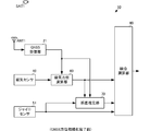
- FIG. 1 is a functional block diagram of an orientation calculation apparatus according to the first embodiment.
- FIG. 2 is a diagram for explaining processing before completion of initialization of the GNSS azimuth in the azimuth calculation apparatus according to the first embodiment.
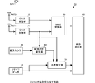
- FIG. 3 is a diagram illustrating processing immediately after initialization of the GNSS azimuth of the azimuth calculation apparatus according to the first embodiment.
- FIG. 4 is a diagram for explaining processing in a steady state after initialization of the GNSS orientation of the orientation calculation apparatus according to the first embodiment.
- the azimuth calculation device 10 includes GNSS receivers 21 and 22, a GNSS calculator 30, a magnetic sensor 40, a gyro sensor 51, a magnetic azimuth calculator 60, an error estimator 70, and an integrated calculator 80.
- the direction calculation device 10 is installed in a moving body such as a ship.
- GNSS is an abbreviation for Global Navigation Satellite System, and is a positioning system.
- the GNSS receiving unit 21 is connected to the GNSS antenna ANT1.
- the GNSS receiver 22 is connected to the GNSS antenna ANT2.
- the GNSS antennas ANT1 and ANT2 are fixed in a predetermined posture with respect to the moving body.
- the GNSS antenna ANT1 receives the GNSS signal from the GNSS satellite SAT1 and outputs it to the GNSS receiver 21.
- the GNSS antenna ANT ⁇ b> 2 receives the GNSS signal from the GNSS satellite SAT ⁇ b> 1 and outputs it to the GNSS receiver 22.
- the GNSS antennas ANT1 and ANT2 receive and output GNSS signals from a plurality of GNSS satellites. At this time, it is preferable to receive GNSS signals from at least four or more GNSS satellites.
- the GNSS receivers 21 and 22 capture and track the GNSS signal, and generate GNSS observation data including the carrier phase.
- the GNSS receivers 21 and 22 calculate the GNSS positioning position using the code pseudorange and the satellite position.
- the satellite position is obtained by demodulating the navigation message superimposed on the GNSS signal.
- the GNSS receivers 21 and 22 output the GNSS observation data and the GNSS positioning position to the GNSS calculator 30.
- the GNSS receiver 21 outputs the GNSS positioning position to the magnetic azimuth calculator 60 and the error estimator 70.
- the GNSS operation unit 30 calculates the GNSS orientation using a plurality of GNSS observation data and the GNSS positioning position. For example, the GNSS calculator 30 calculates the carrier phase difference between the GNSS antennas ANT1 and ANT2 from the GNSS observation data of the GNSS receivers 21 and 22. The GNSS operation unit 30 calculates the GNSS azimuth using this carrier wave phase difference. Thus, since the carrier phase difference is used, the GNSS orientation is highly accurate. The GNSS calculation unit 30 outputs the GNSS orientation and GNSS observation data to the integrated calculation unit 80. The GNSS calculator 30 outputs the GNSS orientation to the error estimator 70.
- the magnetic sensor 40 is fixed to the moving body in a predetermined posture.
- the magnetic sensor 40 detects orthogonal three-axis geomagnetism and outputs it to the magnetic orientation calculation unit 60.
- the gyro sensor 51 is fixed to the moving body in a predetermined posture.
- the gyro sensor 51 detects an angular velocity around three orthogonal axes and outputs the angular velocity to the error estimation unit 70 and the integrated calculation unit 80.
- the magnetic direction calculation unit 60 calculates the magnetic direction based on the geomagnetism. At this time, the magnetic direction calculation unit 60 corrects the magnetic direction using the GNSS positioning position. The magnetic orientation corrected in this way is highly accurate.
- the magnetic direction calculation unit 60 outputs the magnetic direction to the error estimation unit 70 and the integrated calculation unit 80.
- the error estimation unit 70 calculates the change amount of the magnetic orientation, the change amount of the GNSS orientation, and the change amount of the GNSS speed.
- the amount of change in the magnetic orientation is calculated from the magnetic orientation at a plurality of times.
- the change amount of the GNSS azimuth is calculated from the GNSS azimuth at a plurality of times.
- the amount of change in the GNSS speed is calculated from the GNSS position at a plurality of times.
- the error estimation unit 70 estimates the angular velocity bias error using the magnetic azimuth change amount or the GNSS azimuth change amount and the GNSS velocity change amount.
- the error estimation unit 70 outputs the angular velocity bias error to the integrated calculation unit 80.
- the integrated calculation unit 80 corrects the angular velocity using the angular velocity bias error.
- the integrated calculation unit 80 calculates the integrated azimuth using the magnetic azimuth or GNSS azimuth and the corrected angular velocity. By calculating such an integrated azimuth, it is possible to stably calculate a high-precision azimuth rather than using only the individually calculated azimuth.
- the azimuth calculation apparatus 10 selectively executes processing according to the situation as shown below.
- the error estimation unit 70 estimates the angular velocity bias error using the change amount of the magnetic orientation. Since the magnetic orientation is highly accurate, the angular velocity bias error is estimated with high accuracy.
- the integrated calculation unit 80 sets the magnetic direction as the initial direction and calculates the integrated direction. At this time, the magnetic orientation is highly accurate, and the angular velocity is corrected by a highly accurate angular velocity bias error. Therefore, the integrated direction is calculated with high accuracy.
- the angular velocity bias error can be estimated with high accuracy and the integrated orientation can be calculated with high accuracy at the initial stage of calculating the orientation.
- an accuracy condition may be set for the direction (integrated direction) output from the direction calculation device 10. For example, a condition may be set in which the output is performed only when the integrated direction is higher than a predetermined accuracy. In such a case, by using the configuration of the present embodiment, the accuracy condition can be satisfied quickly, and the time from the start of integrated orientation calculation to the output of the integrated orientation can be shortened.
- the error estimation unit 70 estimates the angular velocity bias error using the change amount of the magnetic orientation. As in the first period, since the change amount of the magnetic orientation is highly accurate, the angular velocity bias error is estimated with high accuracy.
- the integration calculation unit 80 calculates the integrated azimuth using the GNSS azimuth, the angular velocity, and the angular velocity bias error. Since the GNSS azimuth and angular velocity bias error are highly accurate, the integrated azimuth is calculated with high accuracy.
- the integration calculation unit 80 calculates the integration direction using the GNSS direction, the angular velocity, and the angular velocity bias error. Since the GNSS azimuth and angular velocity bias error are highly accurate, the integrated azimuth is calculated with high accuracy.
- the angular velocity bias error can be estimated with high accuracy at the initial stage of the azimuth calculation in which the initialization of the GNSS azimuth is not completed, such as immediately after the power is turned on. Further, the integrated azimuth can be calculated with high accuracy from the initial azimuth calculation.
- an accuracy condition is set for the output of the integrated direction, this accuracy condition can be satisfied quickly. Therefore, it is possible to quickly output an integrated orientation having a predetermined accuracy or more after power-on.
- the highly accurate GNSS orientation can be used for the estimation of the angular velocity bias error and the integrated orientation, so that the integrated orientation can be continuously calculated with high accuracy even after the initialization is completed. Can do.
- the GNSS orientation and the magnetic orientation may be used in combination.
- the GNSS orientation may be replaced with a magnetic orientation.
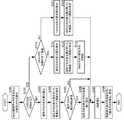
- FIG. 5 is a flowchart of the orientation calculation method according to the first embodiment.
- the processing device generates GNSS observation data and calculates the magnetic orientation after power-on (S101). Specifically, the processing device captures and tracks GNSS signals received by a plurality of GNSS antennas, and generates GNSS observation data including a carrier phase and a code phase. The processing device executes integer value bias and baseline vector determination processing using the GNSS observation data. In parallel with this processing, the processing device acquires the geomagnetism from the magnetic sensor and calculates the magnetic orientation. At this time, the processing apparatus corrects the magnetic orientation using the GNSS positioning position based on the GNSS observation data. This process is continuously performed.
- the processing device calculates the change amount of the magnetic orientation (S103). .
- the processing apparatus estimates the angular velocity bias error using the change amount of the magnetic orientation (S104). At this time, the processing apparatus estimates the angular velocity bias error using the change amount of the GNSS velocity based on the GNSS positioning position.
- the processing device sets the magnetic orientation to the initial value of the integrated orientation (S106).
- the processing apparatus does not set the initial value of the integrated azimuth unless it is immediately after the calculation of the integrated azimuth (S105: NO).
- the processing device corrects the error included in the angular velocity using the estimated angular velocity bias error (S107).
- the processing device calculates and updates the integrated azimuth using the angular velocity after error correction (S108).
- the processing device determines whether or not the initialization of the GNSS orientation has just been completed.
- the processing device calculates the amount of change in the magnetic orientation (S111).
- the processing apparatus estimates the angular velocity bias error using the change amount of the magnetic orientation (S112). At this time, the processing apparatus estimates the angular velocity bias error using the change amount of the GNSS velocity based on the GNSS positioning position.
- the processing device updates the integrated orientation with the GNSS orientation (S113). Thereafter, the processing device corrects the error included in the angular velocity using the estimated angular velocity bias error (S107). The processing device calculates and updates the integrated azimuth using the angular velocity after error correction (S108).
- the processing device calculates the amount of change in the GNSS orientation (S121).
- the processing apparatus estimates an angular velocity bias error using the change amount of the GNSS azimuth (S122).
- the processing apparatus estimates the angular velocity bias error using the change amount of the GNSS velocity based on the GNSS positioning position.
- the processing device corrects the error included in the angular velocity using the estimated angular velocity bias error (S107).
- the processing device calculates and updates the integrated azimuth using the angular velocity after error correction (S108).
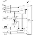
- FIG. 6 is a functional block diagram of the azimuth calculation apparatus according to the second embodiment.
- the azimuth calculation device 10A of the present embodiment is different from the azimuth calculation device 10 according to the first embodiment in that an acceleration sensor 52 and an acceleration attitude angle calculation unit 90 are added.
- the difference is that the processing of the azimuth calculation unit 60A, the error estimation unit 70A, and the integration calculation unit 80A is partially changed.
- Other configurations are the same as those of the azimuth calculation apparatus 10 according to the first embodiment, and the description of the same portions is omitted.
- the acceleration sensor 52 is fixed to the moving body in a predetermined posture.
- the acceleration sensor 52 detects orthogonal three-axis acceleration and outputs it to the error estimation unit 70A, the integrated calculation unit 80A, and the acceleration posture angle calculation unit 90.
- the acceleration posture angle calculation unit 90 calculates a posture angle (acceleration posture angle) from the acceleration.
- the acceleration posture angle calculation unit 90 calculates an acceleration posture angle having at least a roll angle and a pitch angle.
- the acceleration posture angle calculation unit 90 outputs the acceleration posture angle to the magnetic orientation calculation unit 60 and the error estimation unit 70A.
- the magnetic azimuth calculation unit 60A calculates an error based on the attitude of the magnetic sensor 40 with respect to the moving body using the acceleration attitude angle.
- the magnetic orientation calculation unit 60A corrects the magnetic orientation using this error as well. This makes the magnetic orientation more accurate.
- the error estimation unit 70A estimates the acceleration bias error together with the angular velocity bias error.
- the angular velocity bias error is estimated by the same method as the error estimation unit 70. That is, the error estimation unit 70A estimates the angular velocity bias error from the amount of change in the magnetic orientation if it is before or after the completion of the initialization of the GNSS orientation, and after completion of the initialization excluding immediately after the initialization of the GNSS orientation. For example, the angular velocity bias error is estimated from the amount of change in the GNSS orientation.
- the acceleration bias error is estimated from the amount of change in the GNSS speed by calculating the GNSS speed of three orthogonal axes from the acceleration by the GNSS calculator 30. The amount of change in the GNSS speed can also be used for estimating the angular speed bias error.
- the error estimation unit 70A uses the acceleration posture angle for estimation of the angular velocity bias error. Thereby, the angular velocity bias error is estimated with higher accuracy.
- the error estimation unit 70A outputs the angular velocity bias error and the acceleration bias error to the integrated calculation unit 80A.
- the integrated calculation unit 80A corrects the acceleration using the estimated acceleration bias error.
- the integrated calculation unit 80A calculates the integrated azimuth using the angular velocity corrected by the acceleration posture angle. Thereby, the integrated direction is calculated with higher accuracy.
- Direction calculation device 10A Direction calculation devices 21, 22: GNSS reception unit 30: GNSS calculation unit 40: Magnetic sensor 51: Gyro sensor 52: Acceleration sensor 60, 60A: Magnetic direction calculation unit 70, 70A: Error estimation unit 80 , 80A: integrated calculation unit 90: acceleration attitude angle calculation unit ANT1, ANT2: GNSS antenna SAT1: GNSS satellite
Landscapes
- Engineering & Computer Science (AREA)
- Radar, Positioning & Navigation (AREA)
- Remote Sensing (AREA)
- Physics & Mathematics (AREA)
- General Physics & Mathematics (AREA)
- Computer Networks & Wireless Communication (AREA)
- Automation & Control Theory (AREA)
- Position Fixing By Use Of Radio Waves (AREA)
- Navigation (AREA)
Abstract
【課題】統合方位の算出の初期から速やかに高精度な方位を算出する。 【解決手段】GNSS演算部30は、GNSS信号の搬送波位相を含むGNSS観測データを用いてGNSS方位を算出する。磁気方位演算部60は、地磁気を検出して磁気方位を算出する。ジャイロセンサ51は、角速度を検出する。誤差推定部70は、磁気方位の変化量またはGNSS方位の変化量を用いて、角速度に含まれる角速度バイアス誤差を推定する。誤差推定部70は、GNSS方位の初期化が完了する前の第1期間に、磁気方位の変化量を用いて角速度バイアス誤差の推定を行う。統合演算部80は、第1期間に、磁気方位を用いて統合方位を算出し、初期化が完了した後の第2期間に、GNSS方位を用いて統合方位を算出する。
Description
本発明は、GNSS信号とジャイロセンサの角速度とを用いて方位を算出する方位算出装置、方位算出方法、および方位算出プログラムに関する。
従来、各種の方位算出装置が考案されている。例えば、特許文献1には、磁気方位と角速度を用いて方位を算出する電子磁気コンパスが記載されている。磁気方位は、地磁気センサで計測される。角速度は、角速度センサで計測される。特許文献1では、磁気方位に含まれる誤差を、角速度を用いて補正している。
また、従来の方位算出装置として、搬送波位相等のGNSS信号の観測データを用いたものがある。
GNSS信号の観測データと、ジャイロセンサ(角速度センサ)の角速度とを用いた方位算出装置では、GNSS信号の観測データを用いてジャイロセンサの角速度バイアス誤差を推定している。この方位算出装置は、推定された角速度バイアス誤差を用いて、角速度を補正することによって、方位を高精度に算出している。
しかしながら、このような従来の方位算出装置では、電源投入後等の方位算出の初期において方位を高精度に安定させるまで時間がかかることがある。
この発明は、方位算出の初期から速やかに高精度な方位を算出できる方位算出装置、方位算出方法、および、方位算出プログラムを提供することにある。
この発明の方位算出装置は、GNSS演算部、磁気方位演算部、ジャイロセンサ、誤差推定部、および、統合演算部を備える。GNSS演算部は、GNSS信号の搬送波位相を含むGNSS観測データを用いてGNSS方位を算出する。磁気方位演算部は、地磁気に基づく磁気方位を算出する。ジャイロセンサは、角速度を検出する。誤差推定部は、磁気方位の変化量またはGNSS方位の変化量を用いて、角速度に含まれる角速度バイアス誤差を推定する。統合演算部は、磁気方位またはGNSS方位の少なくとも1つ、角速度、および角速度バイアス誤差を用いて、統合方位を算出する。誤差推定部は、GNSS方位の初期化が完了する前の第1期間に、磁気方位の変化量を用いて角速度バイアス誤差の推定を行う。誤差推定部は、GNSS方位の初期化完了後の定常状態である第2期間に、GNSS方位の変化量を用いて角速度バイアス誤差の推定を行う。統合演算部は、第1期間に、磁気方位を用いて統合方位を算出する。統合演算部は、第2期間に、GNSS方位を用いて統合方位を算出する。
この構成では、統合方位が安定して得られていない初期状態において、磁気方位を用いてバイアス誤差が高精度に推定される。これにより、統合方位の算出の初期でも速やかに高精度な方位が得られる。
この発明によれば、統合方位の算出の初期から速やかに高精度な統合方位を算出できる。
本発明の第1の実施形態に係る方位算出装置、方位算出方法、および、方位算出プログラムについて、図を参照して説明する。図1は、第1の実施形態に係る方位算出装置の機能ブロック図である。図2は、第1の実施形態に係る方位算出装置のGNSS方位の初期化完了前の処理を説明する図である。図3は、第1の実施形態に係る方位算出装置のGNSS方位の初期化直後の処理を説明する図である。図4は、第1の実施形態に係る方位算出装置のGNSS方位の初期化後で定常状態の処理を説明する図である。
方位算出装置10は、GNSS受信部21,22、GNSS演算部30、磁気センサ40、ジャイロセンサ51、磁気方位演算部60、誤差推定部70、および、統合演算部80を備える。方位算出装置10は、船舶等の移動体に設置されている。なお、GNSSは、Global Navigation Satellite Systemの略語であり、測位システムである。
GNSS受信部21は、GNSSアンテナANT1に接続されている。GNSS受信部22は、GNSSアンテナANT2に接続されている。GNSSアンテナANT1,ANT2は、移動体に対して所定の姿勢で固定されている。
GNSSアンテナANT1は、GNSS衛星SAT1からのGNSS信号を受信して、GNSS受信部21に出力する。GNSSアンテナANT2は、GNSS衛星SAT1からのGNSS信号を受信して、GNSS受信部22に出力する。なお、図では、1つのGNSS衛星SAT1からのGNSS信号を受信する状態しか記載していないが、GNSSアンテナANT1,ANT2は、複数のGNSS衛星からのGNSS信号を受信して、出力している。この際、少なくとも4つ以上のGNSS衛星からのGNSS信号を受信することが好ましい。
GNSS受信部21,22は、GNSS信号を捕捉、追尾して、搬送波位相を含むGNSS観測データを生成する。また、GNSS受信部21,22は、コード擬似距離と衛星位置とを用いて、GNSS測位位置を算出する。衛星位置は、GNSS信号に重畳された航法メッセージを復調することによって得られる。
GNSS受信部21,22は、GNSS観測データとGNSS測位位置を、GNSS演算部30に出力する。GNSS受信部21は、GNSS測位位置を、磁気方位演算部60および誤差推定部70に出力する。
GNSS演算部30は、複数のGNSS観測データとGNSS測位位置を用いて、GNSS方位を算出する。例えば、GNSS演算部30は、GNSS受信部21,22のGNSS観測データから、GNSSアンテナANT1,ANT2間の搬送波位相差を算出する。GNSS演算部30は、この搬送波位相差を用いてGNSS方位を算出する。このように、搬送波位相差を用いるので、GNSS方位は高精度である。GNSS演算部30は、GNSS方位およびGNSS観測データを、統合演算部80に出力する。GNSS演算部30は、GNSS方位を誤差推定部70に出力する。
磁気センサ40は、所定の姿勢で移動体に固定されている。磁気センサ40は、直交三軸の地磁気を検出して磁気方位演算部60に出力する。
ジャイロセンサ51は、所定の姿勢で移動体に固定されている。ジャイロセンサ51は、直交三軸周りの角速度を検出して、誤差推定部70および統合演算部80に出力する。
磁気方位演算部60は、地磁気に基づいて磁気方位を算出する。この際、磁気方位演算部60は、GNSS測位位置を用いて磁気方位を補正する。このように補正された磁気方位は高精度である。磁気方位演算部60は、磁気方位を誤差推定部70および統合演算部80に出力する。
誤差推定部70は、磁気方位の変化量、GNSS方位の変化量、GNSS速度の変化量を算出する。磁気方位の変化量は、複数時刻の磁気方位から算出される。GNSS方位の変化量は、複数時刻のGNSS方位から算出される。GNSS速度の変化量は、複数時刻のGNSS位置から算出される。誤差推定部70は、磁気方位の変化量またはGNSS方位の変化量、およびGNSS速度の変化量を用いて、角速度バイアス誤差を推定する。誤差推定部70は、角速度バイアス誤差を統合演算部80に出力する。
統合演算部80は、角速度バイアス誤差を用いて角速度を補正する。統合演算部80は、磁気方位またはGNSS方位と、補正後の角速度とを用いて、統合方位を算出する。このような統合方位を算出することによって、個別に算出された方位のみを用いるよりも、高精度な方位を安定して算出することができる。
このような構成において、方位算出装置10は、次に示すように、状況に応じて処理を選択的に実行する。
(1)GNSS方位の初期化完了前(第1期間(図2参照))
GNSS方位の算出には、搬送波位相差から、整数値バイアスを決定し、基線ベクトルを算出する必要がある。方位算出装置10の電源投入直後等の方位算出の初期では、整数値バイアスが決定されておらず、基線ベクトルも算出されていない。GNSS方位の初期化完了とは、この整数値バイアスの決定と基線ベクトルの決定が完了したことを意味する。
GNSS方位の算出には、搬送波位相差から、整数値バイアスを決定し、基線ベクトルを算出する必要がある。方位算出装置10の電源投入直後等の方位算出の初期では、整数値バイアスが決定されておらず、基線ベクトルも算出されていない。GNSS方位の初期化完了とは、この整数値バイアスの決定と基線ベクトルの決定が完了したことを意味する。
このため、GNSS方位の初期化が完了していない第1期間では、高精度なGNSS方位は算出されない。したがって、第1期間では、誤差推定部70は、磁気方位の変化量を用いて角速度バイアス誤差を推定する。磁気方位は高精度であるので、角速度バイアス誤差は、高精度に推定される。
また、統合演算部80は、磁気方位を初期方位に設定し、統合方位を算出する。この際、磁気方位は高精度であり、角速度は、高精度な角速度バイアス誤差によって補正されている。したがって、統合方位は高精度に算出される。
このように、本実施形態に構成を用いることによって、方位算出の初期に、角速度バイアス誤差を高精度に推定でき、統合方位を高精度に算出できる。また、方位算出装置10から出力する方位(統合方位)に、精度条件を設定することがある。例えば、統合方位が所定の精度よりも高い時のみに出力するという条件が設定されていることがある。このような場合、本実施形態の構成を用いることによって、精度条件を速く満たすことが可能であり、統合方位算出の開始から統合方位を出力するまでの時間を短縮することができる。
(2)GNSS方位の初期化完了直後(第3期間(図3参照))
GNSS方位の初期化が完了すると、GNSS演算部30からGNSS方位が出力される。この状態では、まだGNSS方位の変化量を高精度に得ることが容易でない。したがって、第3期間では、誤差推定部70は、磁気方位の変化量を用いて角速度バイアス誤差を推定する。第1期間と同様に、磁気方位の変化量は高精度であるので、角速度バイアス誤差は、高精度に推定される。
GNSS方位の初期化が完了すると、GNSS演算部30からGNSS方位が出力される。この状態では、まだGNSS方位の変化量を高精度に得ることが容易でない。したがって、第3期間では、誤差推定部70は、磁気方位の変化量を用いて角速度バイアス誤差を推定する。第1期間と同様に、磁気方位の変化量は高精度であるので、角速度バイアス誤差は、高精度に推定される。
GNSS方位が算出されているので、統合演算部80は、GNSS方位、角速度、および角速度バイアス誤差を用いて、統合方位を算出する。GNSS方位および角速度バイアス誤差は高精度であるので、統合方位は高精度に算出される。
(3)GNSS方位の初期化完了後で定常状態(第2期間(図4参照))
第2期間である定常状態では、GNSS方位が連続的に算出される。したがって、GNSS方位の変化量を高精度に算出することができる。したがって、第2期間では、誤差推定部70は、GNSS方位の変化量を用いて角速度バイアス誤差を推定する。GNSS方位の変化量は高精度であるので、角速度バイアス誤差は、高精度に推定される。
第2期間である定常状態では、GNSS方位が連続的に算出される。したがって、GNSS方位の変化量を高精度に算出することができる。したがって、第2期間では、誤差推定部70は、GNSS方位の変化量を用いて角速度バイアス誤差を推定する。GNSS方位の変化量は高精度であるので、角速度バイアス誤差は、高精度に推定される。
統合演算部80は、GNSS方位、角速度、および角速度バイアス誤差を用いて、統合方位を算出する。GNSS方位および角速度バイアス誤差は高精度であるので、統合方位は高精度に算出される。
このように、本実施形態の構成を用いることによって、電源投入直後等のGNSS方位の初期化が完了していない方位算出の初期に、角速度バイアス誤差を高精度に推定できる。また、方位算出の初期から統合方位を高精度に算出することができる。
また、統合方位の出力に精度の条件が設定されていれば、この精度の条件を素早く満たすことができる。したがって、所定の精度以上の統合方位を、電源投入後に素早く出力することができる。
また、GNSS方位の初期化完了以降は、高精度なGNSS方位を、角速度バイアス誤差の推定および統合方位に用いることができるので、初期化完了後も継続的に統合方位を高精度に算出することができる。
なお、上述の説明では、GNSS方位の初期化完了後、統合方位の算出にGNSS方位のみを用いる態様を示した。しかしながら、GNSS方位の初期化完了後であっても、GNSS方位と磁気方位を併用してもよい。例えば、GNSS信号を一時的に受信できなくなり、GNSS方位の精度が一時的に劣化するような場合、GNSS方位を磁気方位に置き換えてもよい。
上述の説明では、統合方位の算出の各処理を、複数の機能部で分担して実行する態様を示した。しかしながら、これらの処理をプログラム化して記憶しておき、コンピュータ等の処理装置がこのプログラムを実行してもよい。この場合、処理装置は、図5に示すフローチャートに準じて処理を実行すればよい。図5は、第1の実施形態に係る方位算出方法のフローチャートである。
処理装置は、電源投入後、GNSS観測データの生成および磁気方位の算出を実行する(S101)。具体的には、処理装置は、複数のGNSSアンテナで受信したGNSS信号を捕捉、追尾して、搬送波位相およびコード位相を含むGNSS観測データを生成する。処理装置は、このGNSS観測データを用いて、整数値バイアス、および基線ベクトルの決定処理を実行する。この処理に並行して、処理装置は、磁気センサからの地磁気を取得して、磁気方位を算出する。この際、処理装置は、GNSS観測データに基づくGNSS測位位置を用いて、磁気方位の補正を行う。この処理は、継続的に行われている。
処理装置は、GNSS方位の初期化、すなわち、整数値バイアスの決定および基線ベクトルの算出が完了していない第1期間であれば(S102:NO)、磁気方位の変化量を算出する(S103)。処理装置は、磁気方位の変化量を用いて、角速度バイアス誤差を推定する(S104)。この際、処理装置は、GNSS測位位置に基づくGNSS速度の変化量も用いて、角速度バイアス誤差を推定する。
処理装置は、統合方位の算出開始直後であれば(S105:YES)、磁気方位を統合方位の初期値に設定する(S106)。処理装置は、統合方位の算出開始直後でなければ(S105:NO)、統合方位の初期値の設定を行わない。
処理装置は、推定された角速度バイアス誤差を用いて、角速度に含まれる誤差を補正する(S107)。処理装置は、誤差補正後の角速度を用いて、統合方位を算出して更新する(S108)。
処理装置は、GNSS方位の初期化が完了していれば(S102:YES)、GNSS方位の初期化完了直後か否かを判定する。
処理装置は、GNSS方位の初期化完了直後の第3期間であれば(S110:YES)、磁気方位の変化量を算出する(S111)。処理装置は、磁気方位の変化量を用いて、角速度バイアス誤差を推定する(S112)。この際、処理装置は、GNSS測位位置に基づくGNSS速度の変化量も用いて、角速度バイアス誤差を推定する。
処理装置は、GNSS方位で統合方位を更新する(S113)。この後、処理装置は、推定された角速度バイアス誤差を用いて、角速度に含まれる誤差を補正する(S107)。処理装置は、誤差補正後の角速度を用いて、統合方位を算出して更新する(S108)。
処理装置は、GNSS方位の初期化完了直後でない定常状態の第2期間であれば(S110:NO)、GNSS方位の変化量を算出する(S121)。処理装置は、GNSS方位の変化量を用いて、角速度バイアス誤差を推定する(S122)。この際、処理装置は、GNSS測位位置に基づくGNSS速度の変化量も用いて、角速度バイアス誤差を推定する。この後、処理装置は、推定された角速度バイアス誤差を用いて、角速度に含まれる誤差を補正する(S107)。処理装置は、誤差補正後の角速度を用いて、統合方位を算出して更新する(S108)。
次に、本発明の第2の実施形態に係る方位算出装置について、図を参照して説明する。図6は、第2の実施形態に係る方位算出装置の機能ブロック図である。
図6に示すように、本実施形態の方位算出装置10Aは、第1の実施形態に係る方位算出装置10に対して、加速度センサ52、加速度姿勢角算出部90を追加した点、および、磁気方位演算部60A、誤差推定部70A、統合演算部80Aの処理を部分的に変更した点で異なる。他の構成は、第1の実施形態に係る方位算出装置10と同じであり、同じ箇所の説明は省略する。
加速度センサ52は、所定の姿勢で移動体に固定されている。加速度センサ52は、直交三軸の加速度を検出して、誤差推定部70A、統合演算部80A、および、加速度姿勢角算出部90に出力する。
加速度姿勢角算出部90は、加速度から姿勢角(加速度姿勢角)を算出する。加速度姿勢角算出部90は、少なくともロール角、ピッチ角を有する加速度姿勢角を算出する。加速度姿勢角算出部90は、加速度姿勢角を、磁気方位演算部60および誤差推定部70Aに出力する。
磁気方位演算部60Aは、加速度姿勢角を用いて、移動体に対する磁気センサ40の姿勢に基づく誤差を算出する。磁気方位演算部60Aは、この誤差も用いて、磁気方位を補正する。これにより、磁気方位はさらに高精度になる。
誤差推定部70Aは、角速度バイアス誤差とともに、加速度バイアス誤差を推定する。角速度バイアス誤差は、誤差推定部70と同様の方法によって推定される。すなわち、誤差推定部70Aは、GNSS方位の初期化完了前または完了直後であれば、磁気方位の変化量から角速度バイアス誤差を推定し、GNSS方位の初期化完了直後を除く初期化完了後であれば、GNSS方位の変化量から角速度バイアス誤差を推定する。加速度バイアス誤差は、GNSS演算部30によって加速度から直交三軸のGNSS速度を算出することによって、このGNSS速度の変化量から推定する。このGNSS速度の変化量は、角速度バイアス誤差の推定に利用することもできる。
さらに、誤差推定部70Aは、角速度バイアス誤差の推定に、加速度姿勢角を用いる。これにより、角速度バイアス誤差は、さらに高精度に推定される。誤差推定部70Aは、角速度バイアス誤差と加速度バイアス誤差を統合演算部80Aに出力する。
統合演算部80Aは、推定された加速度バイアス誤差を用いて、加速度を補正する。統合演算部80Aは、加速度姿勢角によって補正された角速度を用いて、統合方位を算出する。これにより、統合方位は、さらに高精度に算出される。
このように、統合方位に角速度と加速度を用いる場合であっても、電源投入直後等の方位算出の初期から高精度な統合方位を算出することができる。また、高精度な統合方位を継続的に算出することができる。
10:方位算出装置
10A:方位算出装置
21,22:GNSS受信部
30:GNSS演算部
40:磁気センサ
51:ジャイロセンサ
52:加速度センサ
60,60A:磁気方位演算部
70,70A:誤差推定部
80,80A:統合演算部
90:加速度姿勢角算出部
ANT1,ANT2:GNSSアンテナ
SAT1:GNSS衛星
10A:方位算出装置
21,22:GNSS受信部
30:GNSS演算部
40:磁気センサ
51:ジャイロセンサ
52:加速度センサ
60,60A:磁気方位演算部
70,70A:誤差推定部
80,80A:統合演算部
90:加速度姿勢角算出部
ANT1,ANT2:GNSSアンテナ
SAT1:GNSS衛星
Claims (10)
- GNSS信号の搬送波位相を含むGNSS観測データを用いてGNSS方位を算出するGNSS演算部と、
地磁気に基づく磁気方位を算出する磁気方位演算部と、
角速度を検出するジャイロセンサと、
前記磁気方位の変化量または前記GNSS方位の変化量を用いて、前記角速度に含まれる角速度バイアス誤差を推定する誤差推定部と、
前記磁気方位または前記GNSS方位の少なくとも1つ、前記角速度、および前記角速度バイアス誤差を用いて、統合方位を算出する統合演算部と、を備え、
前記誤差推定部は、
前記GNSS方位の初期化が完了する前の第1期間に、前記磁気方位の変化量を用いて前記角速度バイアス誤差の推定を行い、
前記GNSS方位の初期化完了後の定常状態である第2期間に、前記GNSS方位の変化量を用いて前記角速度バイアス誤差の推定を行い、
前記統合演算部は、
前記第1期間に、前記磁気方位を用いて統合方位を算出し、
前記第2期間に、前記GNSS方位を用いて前記統合方位を算出する、
方位算出装置。 - 請求項1に記載の方位算出装置であって、
前記誤差推定部は、
前記初期化の完了直後である第3期間に、前記磁気方位の変化量を用いて前記角速度バイアス誤差を推定し、
前記統合演算部は、
前記第3期間に、前記GNSS方位で前記統合方位を更新する、
方位算出装置。 - 請求項1または請求項2に記載の方位算出装置であって、
前記GNSS信号から前記GNSS観測データを算出するとともに、GNSS測位位置を算出するGNSS受信部をさらに備え、
前記磁気方位演算部は、
前記GNSS測位位置を用いて前記磁気方位を算出する、
方位算出装置。 - 請求項3に記載の方位算出装置であって、
前記誤差推定部は、
前記GNSS測位位置に基づくGNSS速度の変化量を用いて前記角速度バイアス誤差を推定する、
方位算出装置。 - 請求項1乃至請求項4のいずれか1項に記載の方位算出装置であって、
前記統合演算部は、
前記第2期間に、前記GNSS方位と前記磁気方位とを併用して、前記統合方位を算出する、
方位算出装置。 - 請求項1乃至請求項5のいずれか1項に記載の方位算出装置であって、
加速度を検出する加速度センサをさらに備え、
前記磁気方位演算部は、
前記加速度から得られる姿勢角を用いて、前記磁気方位を算出し、
前記誤差推定部は、
前記GNSS速度の変化量を用いて加速度バイアス誤差の推定を行い、
前記統合演算部は、
前記加速度バイアス誤差によって補正された加速度と、前記加速度から得られる姿勢角によって補正された角速度とを用いて、前記統合方位を算出する、
方位算出装置。 - GNSS信号の搬送波位相を含むGNSS観測データを用いてGNSS方位を算出し、
地磁気に基づく磁気方位を算出し、
ジャイロセンサを用いて角速度を検出し、
前記磁気方位の変化量または前記GNSS方位の変化量を用いて、前記角速度に含まれる角速度バイアス誤差を推定し、
前記磁気方位または前記GNSS方位の少なくとも1つ、前記角速度、および前記角速度バイアス誤差を用いて、統合方位を算出し、
前記角速度バイアス誤差の推定では、
前記GNSS方位の初期化が完了する前の第1期間に、前記磁気方位の変化量を用いて前記角速度バイアス誤差の推定を行い、
前記GNSS方位の初期化完了後の定常状態である第2期間に、前記GNSS方位の変化量を用いて前記角速度バイアス誤差の推定を行い、
前記統合方位の算出では、
前記第1期間に、前記磁気方位を用いて統合方位を算出し、
前記第2期間に、前記GNSS方位を用いて前記統合方位を算出する、
方位算出方法。 - 請求項7に記載の方位算出方法であって、
前記角速度バイアス誤差の推定では、
前記初期化の完了直後である第3期間に、前記磁気方位の変化量を用いて前記角速度バイアス誤差を推定し、
前記統合方位の算出では、
前記第3期間に、前記GNSS方位で前記統合方位を更新する、
方位算出方法。 - GNSS信号と角速度を用いて方位を算出する処理をコンピュータに実行させる方位算出プログラムであって、
前記コンピュータは、
GNSS信号の搬送波位相を含むGNSS観測データを用いてGNSS方位を算出し、
地磁気に基づいて磁気方位を算出し、
ジャイロセンサを用いて角速度を検出し、
前記磁気方位の変化量または前記GNSS方位の変化量を用いて、前記角速度に含まれる角速度バイアス誤差を推定し、
前記磁気方位または前記GNSS方位の少なくとも1つ、前記角速度、および前記角速度バイアス誤差を用いて、統合方位を算出し、
前記角速度バイアス誤差の推定では、
前記GNSS方位の初期化が完了する前の第1期間に、前記磁気方位の変化量を用いて前記角速度バイアス誤差の推定を行い、
前記GNSS方位の初期化完了後の定常状態である第2期間に、前記GNSS方位の変化量を用いて前記角速度バイアス誤差の推定を行い、
前記統合方位の算出では、
前記第1期間に、前記磁気方位を用いて統合方位を算出し、
前記第2期間に、前記GNSS方位を用いて前記統合方位を算出する、
方位算出プログラム。 - 請求項9に記載の方位算出プログラムであって、
前記コンピュータは、
前記角速度バイアス誤差の推定では、
前記初期化の完了直後である第3期間に、前記磁気方位の変化量を用いて前記角速度バイアス誤差を推定し、
前記統合方位の算出では、
前記第3期間に、前記GNSS方位で前記統合方位を更新する、
方位算出プログラム。
Priority Applications (1)
| Application Number | Priority Date | Filing Date | Title |
|---|---|---|---|
| JP2018543788A JP6732926B2 (ja) | 2016-10-07 | 2017-09-05 | 方位算出装置、方位算出方法、および方位算出プログラム |
Applications Claiming Priority (2)
| Application Number | Priority Date | Filing Date | Title |
|---|---|---|---|
| JP2016198736 | 2016-10-07 | ||
| JP2016-198736 | 2016-10-07 |
Publications (1)
| Publication Number | Publication Date |
|---|---|
| WO2018066291A1 true WO2018066291A1 (ja) | 2018-04-12 |
Family
ID=61831696
Family Applications (1)
| Application Number | Title | Priority Date | Filing Date |
|---|---|---|---|
| PCT/JP2017/031920 Ceased WO2018066291A1 (ja) | 2016-10-07 | 2017-09-05 | 方位算出装置、方位算出方法、および方位算出プログラム |
Country Status (2)
| Country | Link |
|---|---|
| JP (1) | JP6732926B2 (ja) |
| WO (1) | WO2018066291A1 (ja) |
Cited By (1)
| Publication number | Priority date | Publication date | Assignee | Title |
|---|---|---|---|---|
| US20210208232A1 (en) * | 2018-05-18 | 2021-07-08 | Ensco, Inc. | Position and orientation tracking system, apparatus and method |
Citations (3)
| Publication number | Priority date | Publication date | Assignee | Title |
|---|---|---|---|---|
| JPH04283615A (ja) * | 1991-03-13 | 1992-10-08 | Tokimec Inc | ジャイロ装置 |
| JP2006126148A (ja) * | 2004-11-01 | 2006-05-18 | Tokimec Inc | 方位姿勢検出装置 |
| JP2011214833A (ja) * | 2010-03-31 | 2011-10-27 | Fujitsu Ltd | 可搬型携帯端末及び方位推定プログラム |
-
2017
- 2017-09-05 JP JP2018543788A patent/JP6732926B2/ja not_active Expired - Fee Related
- 2017-09-05 WO PCT/JP2017/031920 patent/WO2018066291A1/ja not_active Ceased
Patent Citations (3)
| Publication number | Priority date | Publication date | Assignee | Title |
|---|---|---|---|---|
| JPH04283615A (ja) * | 1991-03-13 | 1992-10-08 | Tokimec Inc | ジャイロ装置 |
| JP2006126148A (ja) * | 2004-11-01 | 2006-05-18 | Tokimec Inc | 方位姿勢検出装置 |
| JP2011214833A (ja) * | 2010-03-31 | 2011-10-27 | Fujitsu Ltd | 可搬型携帯端末及び方位推定プログラム |
Cited By (2)
| Publication number | Priority date | Publication date | Assignee | Title |
|---|---|---|---|---|
| US20210208232A1 (en) * | 2018-05-18 | 2021-07-08 | Ensco, Inc. | Position and orientation tracking system, apparatus and method |
| US11656316B2 (en) | 2018-05-18 | 2023-05-23 | Ensco, Inc. | Position and orientation tracking system, apparatus and method |
Also Published As
| Publication number | Publication date |
|---|---|
| JPWO2018066291A1 (ja) | 2019-07-04 |
| JP6732926B2 (ja) | 2020-07-29 |
Similar Documents
| Publication | Publication Date | Title |
|---|---|---|
| JP5270184B2 (ja) | 衛星航法/推測航法統合測位装置 | |
| CN111801596B (zh) | 用于测定一车辆天线校正信息的方法和装置 | |
| US8560234B2 (en) | System and method of navigation based on state estimation using a stepped filter | |
| US10197681B2 (en) | State calculating device, method of calculating state, and state calculating program | |
| JP4412381B2 (ja) | 方位検出装置 | |
| CN1910428A (zh) | 在深度集成的导航系统中使用多个辅助传感器的系统和方法 | |
| US12585027B2 (en) | Positioning system and method | |
| JP5605539B2 (ja) | 移動体位置推定追尾装置、移動体位置推定追尾方法、及び移動体位置推定追尾プログラム | |
| US10948292B2 (en) | Sensor error calculating device, attitude angle calculating apparatus, method of calculating sensor error and method of calculating attitude angle | |
| JP5301762B2 (ja) | キャリア位相相対測位装置 | |
| JP2008038418A (ja) | 測位装置及び初期化方法 | |
| JP2008232867A (ja) | 移動体の姿勢及び方位検出装置 | |
| JP2008232771A (ja) | 測位装置 | |
| WO2021006243A1 (ja) | アンテナ間相対位置推定方法、アンテナ間相対位置推定装置及びアンテナ間相対位置推定プログラム | |
| JP6732926B2 (ja) | 方位算出装置、方位算出方法、および方位算出プログラム | |
| US10877163B2 (en) | Method and device for calculating attitude angle | |
| JP2012202749A (ja) | 方位測定装置 | |
| WO2020110996A1 (ja) | 測位装置、速度測定装置、及びプログラム | |
| JP2015102330A (ja) | 移動情報算出装置、移動情報算出方法、移動情報算出プログラム、および移動体 | |
| KR20250037490A (ko) | 모션-보상된 신호 처리를 수행하는 방법 및 장치 | |
| US20190369267A1 (en) | Azimuth angle calculating device, and method of calculating azimuth angle | |
| JP5180447B2 (ja) | キャリア位相相対測位装置及び方法 | |
| JP2015068714A (ja) | 姿勢検出装置及びこれを備えた移動体、並びに、姿勢検出方法 | |
| JP2002162458A (ja) | 方位測定装置 | |
| JP2002286829A (ja) | 絶対位置推定装置 |
Legal Events
| Date | Code | Title | Description |
|---|---|---|---|
| 121 | Ep: the epo has been informed by wipo that ep was designated in this application |
Ref document number: 17858130 Country of ref document: EP Kind code of ref document: A1 |
|
| ENP | Entry into the national phase |
Ref document number: 2018543788 Country of ref document: JP Kind code of ref document: A |
|
| NENP | Non-entry into the national phase |
Ref country code: DE |
|
| 122 | Ep: pct application non-entry in european phase |
Ref document number: 17858130 Country of ref document: EP Kind code of ref document: A1 |