WO2018062530A1 - マイクロニードルアレイ及びその製造方法 - Google Patents
マイクロニードルアレイ及びその製造方法 Download PDFInfo
- Publication number
- WO2018062530A1 WO2018062530A1 PCT/JP2017/035640 JP2017035640W WO2018062530A1 WO 2018062530 A1 WO2018062530 A1 WO 2018062530A1 JP 2017035640 W JP2017035640 W JP 2017035640W WO 2018062530 A1 WO2018062530 A1 WO 2018062530A1
- Authority
- WO
- WIPO (PCT)
- Prior art keywords
- microneedle
- microneedle array
- microneedles
- pairs
- skin
- Prior art date
- Legal status (The legal status is an assumption and is not a legal conclusion. Google has not performed a legal analysis and makes no representation as to the accuracy of the status listed.)
- Ceased
Links
Images




Classifications
-
- A—HUMAN NECESSITIES
- A61—MEDICAL OR VETERINARY SCIENCE; HYGIENE
- A61M—DEVICES FOR INTRODUCING MEDIA INTO, OR ONTO, THE BODY; DEVICES FOR TRANSDUCING BODY MEDIA OR FOR TAKING MEDIA FROM THE BODY; DEVICES FOR PRODUCING OR ENDING SLEEP OR STUPOR
- A61M37/00—Other apparatus for introducing media into the body; Percutany, i.e. introducing medicines into the body by diffusion through the skin
- A61M37/0015—Other apparatus for introducing media into the body; Percutany, i.e. introducing medicines into the body by diffusion through the skin by using microneedles
-
- A—HUMAN NECESSITIES
- A61—MEDICAL OR VETERINARY SCIENCE; HYGIENE
- A61M—DEVICES FOR INTRODUCING MEDIA INTO, OR ONTO, THE BODY; DEVICES FOR TRANSDUCING BODY MEDIA OR FOR TAKING MEDIA FROM THE BODY; DEVICES FOR PRODUCING OR ENDING SLEEP OR STUPOR
- A61M37/00—Other apparatus for introducing media into the body; Percutany, i.e. introducing medicines into the body by diffusion through the skin
- A61M37/0015—Other apparatus for introducing media into the body; Percutany, i.e. introducing medicines into the body by diffusion through the skin by using microneedles
- A61M2037/0046—Solid microneedles
-
- A—HUMAN NECESSITIES
- A61—MEDICAL OR VETERINARY SCIENCE; HYGIENE
- A61M—DEVICES FOR INTRODUCING MEDIA INTO, OR ONTO, THE BODY; DEVICES FOR TRANSDUCING BODY MEDIA OR FOR TAKING MEDIA FROM THE BODY; DEVICES FOR PRODUCING OR ENDING SLEEP OR STUPOR
- A61M37/00—Other apparatus for introducing media into the body; Percutany, i.e. introducing medicines into the body by diffusion through the skin
- A61M37/0015—Other apparatus for introducing media into the body; Percutany, i.e. introducing medicines into the body by diffusion through the skin by using microneedles
- A61M2037/0053—Methods for producing microneedles
Definitions
- the present invention relates to a microneedle array and a manufacturing method thereof.
- Microneedle array technology is a technology that enables the product to adhere to the skin regardless of the adhesive.
- a microneedle having a fine needle-like shape is pierced into the keratin of the skin, and the tip thereof stays in the keratin, whereby mechanical adhesion can be realized.
- Patent Document 1 describes a microneedle array in which the tip of a microneedle is bent in one direction, which is easily pierced into the skin and difficult to come out of the skin.
- patent document 2 the wound closure device which provided the microstructures, such as a microneedle, in the base-material part of the both sides of the base-material part for closing a wound is described.
- an object of the present invention is to provide a microneedle array capable of strongly adhering to a very small living body part.
- microneedle array when the microneedle array is configured, the microneedles are arranged to face each other, thereby obtaining the effect of tweezers (hereinafter also referred to as “microtweezers”) at a micro level.
- microtweezers hereinafter also referred to as “microtweezers”.
- the present invention has been completed.
- the gist of the present invention is as follows.
- a plurality of microneedles are erected on a substrate in a state where the extending direction of the microneedles is inclined with respect to a direction perpendicular to the surface of the substrate.
- a plurality of the microneedle pairs are arranged on a straight line extending along the arrangement direction of the microneedle pairs.
- a plurality of the microneedle pairs are provided in a direction orthogonal to the arrangement direction of the microneedle pairs.
- the base material preferably has stretchability, and the base material preferably has a Young's modulus of 100 MPa or less, and the microneedle has a polylactic acid resin, acrylonitrile- It is preferably made of at least one selected from the group consisting of butadiene-styrene resins.
- the microneedles extend so that an angle formed between the extending direction of the microneedles and the surface of the base material gradually decreases.
- the method for producing a microneedle array according to the present invention prepares a structure in which a plurality of microneedles are erected using a template, and then pressurizes the structure from both sides in the extending direction of the microneedle. The microneedle is heated.
- microneedle array capable of strongly adhering to a very small living body part.
- FIG. 1 It is a figure which shows the microneedle array of an example of this invention.
- A is a figure which shows the upper side figure of a microneedle array
- (b) is a figure which shows sectional drawing when a microneedle array is cut
- (A)-(g) is a figure which shows each process.
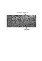
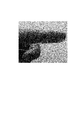
- (A) is a photograph of the appearance when the microneedle made of PLA resin of Example 1 prepared in “B-2.” Of Example is observed using an optical microscope.
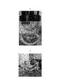
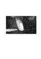
- (B) is a photograph of the appearance when the microneedle made of PLA resin of Example 3 in which the shape of the tip produced in “B-3.” Of Example is changed is observed using an optical microscope.
- 6 is a photograph of an external appearance of an ABS resin microneedle manufactured in Example 2 “B-2.” When observed using an optical microscope. It is a photograph when the microneedle array made of PLA resin of Example 4 manufactured in “B-4.” Of Example is observed with the naked eye.
- FIG. 1 shows a microneedle array as an example of the present invention.
- A shows a top view of the microneedle array, and
- B shows a cross-sectional view when the microneedle array is cut along a plane along line AA in (a).
- microneedle array 1 (hereinafter also referred to as “microneedle array 1”) of an example of the present invention has a plurality of microneedles 2 on a base material 3 and the extending direction of the microneedles 2 is the surface of the base material 3.
- the microneedle array is erected in a state of being inclined with respect to a direction perpendicular to (see FIG. 1B).
- the microneedle array 1 includes a plurality of microneedle pairs 2p in which one microneedle 2a and the other microneedle 2b face each other in two adjacent microneedles 2 (2a, 2b). (See FIGS. 1A and 1B). Note that the microneedles 2 face each other means that the extending direction of one microneedle 2a and the extending direction 2b of the other microneedle are opposite on the same straight line (however, both In the strict sense, the extending directions do not have to be opposite directions on the same straight line, and both extending directions have components in opposite directions to each other).
- the extending direction of the microneedle 2 refers to a direction from the bottom 2B of the microneedle 2 toward the end 2E.
- the microneedle array 1 includes a plurality of the microneedle pairs 2p with respect to the arrangement direction of the microneedle pairs 2p. (See FIG. 1 (a)).
- the arrangement direction of the microneedle pair 2p refers to the direction of a line connecting one microneedle 2a and the other microneedle 2b.
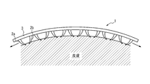
- FIG. 2 shows a state when the microneedle array of the example of the present invention shown in FIG. 1 is attached to the skin.
- the microneedle array 1 is affixed to the surface of a living body (for example, skin)
- both tips of the two microneedles 2a and 2b facing each other in the microneedle pair 2p pierce the surface of the living body.
- the epidermis is sandwiched between both ends by the inclination of the microneedles 2, and the microneedle array 1 is immobilized on the surface of the living body.
- the two microneedles 2a and 2b facing each other in the microneedle pair 2p act as tweezers (microtweezers) at the micro level, and the microneedle array 1 is immobilized on the surface of the living body. An effect is acquired (refer FIG. 2).
- the microneedle array 1 of the present embodiment it is not necessary to use an adhesive such as an acrylic adhesive or a silicone adhesive, and thus the surface of the living body is unlikely to be rash.
- microneedle array 1 of the present embodiment when the microneedle array 1 is attached to the surface of a living body, a slight gap (see arrows in FIG. 2) is provided between the surface of the living body and the base material. Since it can be provided, it is possible to keep the surface of the living body in a dry state, and it is difficult for the living body to be stuffy, and sweating can be suppressed (see FIG. 2). In addition, it is possible to suppress a decrease in adhesion between the surface of the living body and the microneedle array 1 due to steaming or sweating.
- the microneedle array 1 includes a plurality of microneedle pairs 2p with respect to the arrangement direction of the microneedle pair 2p, even if the microneedle array 1 is divided into a plurality with respect to the arrangement direction of the microneedle pair 2p, In each of the divided microneedle arrays 1, the effect of immobilization on the surface of the living body by microtweezers can be obtained independently. Thereby, the microneedle array 1 of this embodiment can be affixed also to the very small biological body part. In addition, the microneedle array 1 of the present embodiment can be used by being appropriately divided (cut) according to the size of the living body part to be attached.
- microtweezers can be ubiquitous on the base material 3, so that it is usually difficult to keep the adhesive product to adhere (for example, the inner part of the elbow or the neck to the chin). It is possible to attach to a living body part capable of forming a concave surface such as a part up to 2) with high adhesion.
- a plurality of microneedle pairs 2p are arranged on a straight line extending along the arrangement direction of the microneedle pairs 2p.
- a plurality of microneedle pairs 2p are arranged on a straight line extending along a direction orthogonal to the arrangement direction of the microneedle pairs 2p.
- the microtweezers can be disposed on the base material in a direction orthogonal to the direction in which the microneedle pair 2p is disposed, and the adhesion and adhesion of the microneedle array 1 to the surface of the living body are further improved. be able to.
- a plurality of microneedle pairs 2p may not be arranged on a straight line extending in a direction orthogonal to the arrangement direction of the microneedle pairs 2p. Even if a plurality of directions are provided in the direction orthogonal to the arrangement direction, the same effect as the effect of improving the adhesiveness and adhesion can be obtained.
- microneedle array 1 shown in FIG. 1 a plurality of independent microneedles 2 are erected on the base material 3, but the microneedle of the present invention is composed of the same material for the microneedle 2 and the base material 3. May be prepared.
- the arrangement relationship between the arrangement direction of the microneedle pair 2p and the direction orthogonal to the arrangement direction of the microneedle pair 2p and the outer edge of the microneedle array 1 is not particularly limited, but the planar view shape of the microneedle array 1 is rectangular.
- the arrangement direction of the microneedle pair 2p may be a direction along the long side of the microneedle array 1
- the direction orthogonal to the arrangement direction of the microneedle pair 2p may be a direction along the short side of the microneedle array 1.
- the substrate 3 of the microneedle array 1 preferably has stretchability. Paying attention to the vicinity of the microtweezers, the direction in which the base material 3 contracts and the extending direction of the two microneedles 2a, 2b forming the microneedle pair 2p coincide with each other, so that the microneedle 2 can be inserted deeper. It becomes possible, and the adhesiveness and adhesiveness with respect to the surface of the living body of the microneedle array 1 can further be improved.
- the Young's modulus of the substrate 3 is preferably 100 MPa or less, more preferably 10 MPa or less, and preferably 5 kPa or more.
- the Young's modulus is a value measured using a tensile tester (model: Imada ZTA-5N) under the condition of a tensile speed of 2 mm / min. If the Young's modulus of the base material is within the above range, the microneedle array 1 of this embodiment is attached to the living body after being attached while suppressing the force required to stretch the microneedle array 1 of this embodiment. The force to fasten to the surface can be obtained.
- Examples of the material of the base material 3 include polyurethane resin, double network gel, polylactic acid resin added with a plasticizer, and styrene-butadiene rubber (SBR). From the viewpoint of adhesion to microneedles and ease of molding, A polylactic acid resin added with a plasticizer and styrene-butadiene rubber (SBR) are preferred.
- Examples of the material of the microneedle 2 include polylactic acid (PLA) resin, acrylonitrile-butadiene-styrene (ABS) resin, polystyrene, polymethyl methacrylate (PMMA) resin, and polyglycidyl methacrylate (PGMA) resin.
- PLA resin excellent in biological safety and flexibility during heating, and ABS resin excellent in rigidity, biological safety and impact resistance are preferable.
- the material of the microneedle 2 and the material of the base material 3 may be the same or different.
- FIG. 3 is an enlarged cross-sectional view of a microneedle pair provided in the microneedle array of the example of the present invention shown in FIG.
- the three-dimensional shape of the microneedle 2 is not particularly limited as long as it can be inserted into the skin, and examples thereof include a truncated cone shape, a cone shape, a quadrangular pyramid shape, a quadrangular pyramid shape, and modifications thereof.
- a frustoconical shape is preferred.
- the diameter Rb of the bottom circle of the frustoconical shape of the microneedle 2 may be 20 to 500 ⁇ m, and is 100 to 400 ⁇ m from the viewpoint of ease of production, ease of penetration into the skin, and mechanical strength. For example, it may be 300 ⁇ m.
- the diameter Rt of the circle on the top surface may be 1 to 50 ⁇ m, and is preferably 5 to 20 ⁇ m, for example, 10 ⁇ m from the viewpoint of ease of production and ease of penetration into the skin.
- the height H may be 20 to 1000 ⁇ m, and is preferably 30 to 600 ⁇ m from the viewpoint of ensuring a sufficient contact area with the epidermis after penetrating the stratum corneum and preventing invasion to the dermis, for example, 600 ⁇ m It may be.
- the dimensions of the microneedles 2 may be the same or different for the plurality of microneedles 2.
- the distance D1 (the distance between the bottom centers) between the microneedles 2a and 2b in the microneedle pair 2p may be 100 to 5000 ⁇ m, and preferably 500 to 2000 ⁇ m.
- the distance D2 (distance between end portions) between the tips of the microneedles 2a and 2b in the microneedle pair 2p may be 5 to 2000 ⁇ m, and preferably 10 to 500 ⁇ m.
- the distance d (see FIG. 1 (a)) between the adjacent microneedle pairs 2p1 and 2p2 in the arrangement direction of the microneedle pair 2p is preferably 0 to 2000 ⁇ m, and more preferably 0 to 1000 ⁇ m.
- the pitch P (see FIG.
- microneedle pair 2p in the direction orthogonal to the arrangement direction of the microneedle pair 2p is preferably 500 to 3000 ⁇ m, more preferably 1000 to 2000 ⁇ m.
- the dimensions of the microneedle pair 2p may be the same or different for the plurality of microneedle pairs 2p.
- the thickness t of the substrate 3 may be 10 to 2000 ⁇ m, and preferably 300 to 1000 ⁇ m.
- the angle ⁇ (see FIG. 1B) formed by the extending direction of the microneedles 2 and the surface of the substrate 3 is preferably 15 to 75 °, and more preferably 30 to 60 °. Note that the angle ⁇ is defined with respect to a line connecting the centers of the cross sections of the microneedles 2, and may be one or plural over the entire length of the microneedles 2. When there are a plurality of angles ⁇ , the microneedle 2 has a multistage shape.
- the microneedles 2 extend so that the angle ⁇ between the extending direction of the microneedles 2 and the surface of the substrate 3 gradually decreases. . According to such a configuration, the microneedle 2 can be easily inserted and hardly removed.
- the radius of curvature R of the microneedle 2 may be 10 to 2000 ⁇ m, and preferably 100 to 1000 ⁇ m, from the viewpoint of securing the holding power to the skin and the ease of manufacturing.
- microneedle 2 and the base material 3 may be adhere
- a structure in which a plurality of microneedles is erected is prepared using a template, and then the structure is pressurized from both sides in the extending direction of the microneedle. The microneedle is heated.
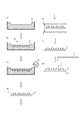
- FIG. 4 shows an outline of a method for producing a microneedle array as an example of the present invention. Each step is shown in (a) to (g).
- a template 11 is prepared (see FIG. 4A).
- examples of the material of the original mold 11 include a Teflon (registered trademark) plate and an acrylic plate.
- the master mold 11 is cut to produce a female mold 10 having a gap 12 that is a portion corresponding to the microneedle 2 (see FIG. 4B).
- the cutting method is not particularly limited, and examples thereof include drilling and laser processing.
- the shape, size, etc. of the gap 12 may be the shape, size, etc. matched to the shape and size of the microneedle 2 described above.
- the angle formed between the extending direction of the gap 12 and the surface of the prototype 11 may be 15 to 75 °, similar to the angle ⁇ described above.
- the material 13 (for example, resin) of the microneedle 2 is melted (see FIG. 4C).
- the material 13 of the microneedle 2 is as described above for the microneedle 2.
- the melting conditions may be appropriately selected according to the material 13.
- the temperature may be a temperature equal to or higher than the glass transition point when the material 13 is a resin.
- the environment may be a reduced pressure or an inert gas atmosphere.
- the molten material 13 is added to the female mold 10, and then the female mold 10 is cooled to solidify the resin (see FIG. 4C). At this time, the melted material 13 may be added to all the individual gaps 12 (not shown), or the melted material 13 may be added so that all the gaps 12 are immersed (see FIG. 4C). ). Further, from the viewpoint of adjusting the shape of the end 1E, it is preferable to place the female mold 10 under reduced pressure (for example, 10 to 100 hPa) and deaerate the gap 12 after adding the material and before cooling the mold.
- reduced pressure for example, 10 to 100 hPa
- the cooled and solidified material 13 is taken out from the mold to obtain a structure 14 in which the microneedles 2 are erected (see FIG. 4D).
- the microneedles 2 are further heated while the obtained structure 14 is pressurized from both sides in the extending direction of the microneedles 2 (see FIG. 4E). This step further increases the inclination of the microneedle 2 (see FIG. 4F).
- the method of pressurization and heating is not particularly limited, and a commercially available press can be used.
- the pressure is not particularly limited, and may be 100 kPa to 5 MPa.
- the temperature may be 10 to 20 ° C. higher than the melting point or the glass transition point when the material 13 is a resin.
- the base member 3 is attached to the obtained structure 14 using an adhesive to obtain the microneedle array 1 (see FIG. 4G).
- the adhesive may be appropriately selected according to the materials of the microneedles 2 and the substrate 3, and is not particularly limited.
- a cyanoacrylate adhesive product name: Aron Alpha jelly form
- Aron Alpha jelly form a cyanoacrylate adhesive
- Material A-1 Commercially available reagents / equipment / Teflon plate (5 mm thick) (manufactured by ASONE) Polylactic acid (filament for 3D printer) (manufactured by XYZ Printing). The filament was cut to a length of 5 mm to form a pellet. ⁇ Plasticizer (Daifitty manufactured by Daihachi Chemical Co., Ltd.) ⁇ Small diameter taper end mill (tip diameter 20 ⁇ m) (Ducraft)
- a Teflon plate (3 cm ⁇ 3 cm) which is a prototype of a female mold was placed in a container (see FIG. 4A).
- a conical small-diameter tapered end mill and a 5-axis cutting machine a shape serving as a female mold for a microneedle array was carved on a Teflon plate.
- a female mold of a microneedle array provided with microneedles extending obliquely with respect to the direction perpendicular to the substrate was produced (see FIG. 4B).
- microneedle dimensions were as follows. -Bottom circle diameter Rb: 400 ⁇ m -Diameter of top circle Rt: 50 ⁇ m -Height H: 430 ⁇ m -Microneedle angle ⁇ : 30 ° ⁇ Distance D1: 1900 ⁇ m ⁇ Distance D2: 820 ⁇ m -Number of microneedle pairs: 4 in the vertical direction and 4 in the horizontal direction-Distance d between microneedle pairs: 1.4 mm ⁇ Pitch P in the direction orthogonal to the arrangement direction of the microneedle pair: 2 mm
- FIG. 5 (a) shows an external view of a photograph of the microneedle made of PLA resin of Example 1 made in “B-2.” Of the Example, which is observed using an optical microscope.
- the specifications are further changed in “B-1.” And “B-2.”,
- an MNA was prepared in the same manner as in Example 1 except that ABS resin was used instead of PLA resin (Example 2).
- FIG. 6 shows an external view of a photograph of an ABS resin microneedle produced in Example 2 “B-2.” When observed using an optical microscope.
- FIG. 5 (b) shows an external view of a photograph of the microneedle of Example 3 in which the shape of the tip produced in “B-3.” Of the example was changed, which was observed using an optical microscope.
- FIG. 7 shows a photograph of the microneedle array of Example 4 produced in “B-4.” Of the example when observed with the naked eye.
- the number of MNs is the same as the number of MNs in the MNA of Example 1 on the flexible member according to the description in JP-T-2015-523139, and the MN is inclined in one direction.
- An MNA including a first MN disposition region including the MN, a non-MN disposition region, and a second MN disposition region including the MN inclined in the direction opposite to the one direction was separately manufactured.
- microneedle array C-1 Evaluation of adhesion to skin
- the prepared MNA microneedle angle ⁇ : 30 °
- MNA force gauge
- the maximum resistance (N / cm 2 ) when pulled by -1KE-5N) was defined as the adhesion to the skin and measured.
- the adhesive force to the skin per unit area of the MNA of Example 1 was 0.16 ⁇ 0.05 N / cm 2 .
- the adhesive strength to the skin per MN was 10 ⁇ 3 mN.
- the adhesion force to the skin per MN was 13 ⁇ 3 mN.
- the adhesive strength to the skin per unit area of the MNA of Comparative Example 1 was 0.43 ⁇ 0.10 N / cm 2 .
- the adhesive strength of the medical adhesive film (manufactured by 3M, Nexcare) and the poultice (manufactured by Hisamitsu Pharmaceutical Co., Ltd., Salon Pass) to the skin was measured, respectively, 2.24 ⁇ 0.31 N / cm 2. 0.46 ⁇ 0.16 N / cm 2 . From this result, it is clear that the MNA produced in this example has sufficient adhesion to the skin to support its own weight (adhesion to the skin at least about one-third that of a commercially available compress). It was.
- the MNA of Example 1 strongly adhered to the skin and could withstand deformation of the skin (see FIG. 8 (a)).
- the evaluation was A.
- the shape of the MNA was adjusted in advance to a shape along the concave surface of the pig skin. Specifically, MNA was placed on a curved surface (convex surface) and heated at 120 ° C.
- FIG. 8A shows a state before MNA is applied to pig skin.
- the MN non-arranged region floated, causing difficulty in close contact with the skin (see FIG. 8B). Evaluation was C.
- FIG. 9 shows a photograph of the state when the microneedle array of Example 4 was attached to the abdomen of the index finger and the hand was shaken up and down and left and right. It was shown that the microneedle array has an adhesiveness that does not leave the finger even when the hand is shaken.
- FIG. 10 shows a photograph of the state when water vapor was sprayed between the microneedle array and the skin after the microneedle array of Example 4 was attached to the abdomen of the index finger. It was shown that there is a space through which water vapor can pass between the microneedle array and the skin.
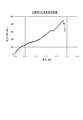
- FIG. 11 is a chart showing the relationship between displacement and stress when the adhesiveness evaluation described in “C-1.” Is performed for the MNA of Comparative Example 1. The vertical axis represents stress (mN / cm 2 ), and the horizontal axis represents displacement (mm). In the case of Comparative Example 1, it was shown that the stress increased in proportion to the displacement, and the adhesiveness was lost at a stroke when the predetermined displacement was reached.
- the present invention it is possible to provide a microneedle array capable of strongly adhering to a very small living body part.
Landscapes
- Health & Medical Sciences (AREA)
- Engineering & Computer Science (AREA)
- Dermatology (AREA)
- Medical Informatics (AREA)
- Anesthesiology (AREA)
- Biomedical Technology (AREA)
- Heart & Thoracic Surgery (AREA)
- Hematology (AREA)
- Life Sciences & Earth Sciences (AREA)
- Animal Behavior & Ethology (AREA)
- General Health & Medical Sciences (AREA)
- Public Health (AREA)
- Veterinary Medicine (AREA)
- Media Introduction/Drainage Providing Device (AREA)
Abstract
複数のマイクロニードルが、基材上に、マイクロニードルの延在方向が基材の表面に垂直な方向に対して傾斜している状態で、立設されているマイクロニードルアレイであって、隣接する2つのマイクロニードルにおいて一方のマイクロニードルと他方のマイクロニードルとが対向しているようなマイクロニードルペアを、マイクロニードルペアの配置方向に関して複数備える、ことを特徴とする、マイクロニードルアレイ、及びその製造方法。
Description
本発明は、マイクロニードルアレイ及びその製造方法に関する。
皮膚に貼り付けて用いられる製品は、創傷の被覆の用途に留まらず、体液のサンプリングや、体液成分の計測による生体情報のセンシング等の用途においても、近年その需要が高まっている。皮膚貼付用の製品(例えば、医療用テープ等)には、一般的に、アクリル系粘着剤やシリコン系粘着剤が用いられており、粘着剤が製品と皮膚とを接着させている。しかしながら、これら粘着剤と皮膚とが長時間接触すると、皮膚に蒸れやかぶれを生じさせることがあり、また、粘着剤の粘着力は発汗等による皮膚の表面の濡れによって低下してしまうことがある。
製品と皮膚との接着を粘着剤によらず可能にする技術として、マイクロニードルアレイ技術がある。微小な針状の形状を有するマイクロニードルが、皮膚の角質に突き刺さり、その先端が、角質内に留まることによって、機械的な接着を実現することができる。
例えば、特許文献1では、皮膚に刺さりやすく、且つ皮膚から抜けにくい、微小針の先端部が一方向に曲がった微小針アレイが記載されている。また、特許文献2では、創傷を閉鎖するための基材部分の両側の基材部分にマイクロニードル等の微細構造を設けた、創傷閉鎖デバイスが記載されている。
しかしながら、上記特許文献1の技術では、製造方法上の制約から、先端部が一定方向のみに曲がったマイクロニードルシートしか製造することができず、シートを皮膚に留めておける時間が十分ではない可能性がある。
また、上記特許文献2の技術では、マイクロニードル等の微細構造を創傷を閉鎖するための基材部分を挟んで設けることを前提としているため、マイクロニードルアレイのサイズが比較的大きなものとなり、マイクロニードルアレイを貼り付けることが可能な生体部位が限定されるおそれがあった。
そこで、本発明は、極めて小さいサイズの生体部位にも強く接着させることが可能なマイクロニードルアレイを提供することを目的とする。
発明者らは、マイクロニードルアレイを構成するにあたり、マイクロニードルを向かい合わせて配置することによって、マイクロレベルでのピンセット(以下、「マイクロピンセット」ともいう。)の作用効果を得ることに想到し、本発明を完成させた。
本発明の要旨は以下の通りである。
本発明の要旨は以下の通りである。
本発明のマイクロニードルアレイは、複数のマイクロニードルが、基材上に、前記マイクロニードルの延在方向が前記基材の表面に垂直な方向に対して傾斜している状態で、立設されているマイクロニードルアレイであって、隣接する2つの前記マイクロニードルにおいて一方の前記マイクロニードルと他方の前記マイクロニードルとが対向しているようなマイクロニードルペアを、前記マイクロニードルペアの配置方向に関して複数備える、ことを特徴とする。
ここで、本発明のマイクロニードルアレイは、前記マイクロニードルペアが、前記マイクロニードルペアの配置方向に沿って延びる直線上に複数並んでいることが好ましい。
また、本発明のマイクロニードルアレイは、前記マイクロニードルペアが、前記マイクロニードルペアの配置方向に直交する方向に関して複数備えることが好ましい。
また、本発明のマイクロニードルアレイは、前記マイクロニードルペアが、前記マイクロニードルペアの配置方向に直交する方向に関して複数備えることが好ましい。
更に、本発明のマイクロニードルアレイは、前記基材が、伸縮性を備えることが好ましく、前記基材のヤング率が、100MPa以下であることが好ましく、前記マイクロニードルが、ポリ乳酸樹脂、アクリロニトリル-ブタジエン-スチレン樹脂からなる群から選択される少なくとも1種からなることが好ましい。
更に、本発明のマイクロニードルアレイは、前記マイクロニードルが、前記マイクロニードルの延在方向と前記基材の表面とのなす角度が漸減するように延びることが好ましい。
本発明のマイクロニードルアレイの製造方法は、鋳型を用いて複数のマイクロニードルが立設されている構造体を調製し、その後、前記構造体を前記マイクロニードルの延在方向両側から加圧しつつ前記マイクロニードルを加熱する、ことを特徴とする。
本発明によれば、極めて小さいサイズの生体部位にも強く接着させることが可能なマイクロニードルアレイを提供することができる。
以下、図面を参照して、本発明のマイクロニードルアレイ、及び本発明のマイクロニードルアレイの製造方法の実施形態について詳細に例示説明する。
(マイクロニードルアレイ)
図1に、本発明の一例のマイクロニードルアレイを示す。(a)に、マイクロニードルアレイの上面図を示し、(b)に、マイクロニードルアレイを(a)の線A-Aに沿う面により切断した時の断面図を示す。
図1に、本発明の一例のマイクロニードルアレイを示す。(a)に、マイクロニードルアレイの上面図を示し、(b)に、マイクロニードルアレイを(a)の線A-Aに沿う面により切断した時の断面図を示す。
本発明の一例のマイクロニードルアレイ1(以下、「マイクロニードルアレイ1」ともいう。)は、複数のマイクロニードル2が、基材3上に、マイクロニードル2の延在方向が基材3の表面に垂直な方向に対して傾斜している状態で、立設されているマイクロニードルアレイである(図1(b)参照)。
そして、マイクロニードルアレイ1は、隣接する2つのマイクロニードル2(2a、2b)において一方のマイクロニードル2aと他方のマイクロニードル2bとが対向しているようなマイクロニードルペア2pを、複数備えている(図1(a)、(b)参照)。
なお、マイクロニードル2が対向するとは、一方のマイクロニードル2aの延在方向と、他方のマイクロニードルの延在方向2bとが、同一直線上で反対方向となっていることをいう(但し、両延在方向が厳密な意味で同一直線上で反対方向となっていなくてもよく、両延在方向が互いに反対方向の成分を有していることもいうものとする)。
また、マイクロニードル2の延在方向とは、マイクロニードル2の底部2Bから端部2Eに向かう方向をいう。
なお、マイクロニードル2が対向するとは、一方のマイクロニードル2aの延在方向と、他方のマイクロニードルの延在方向2bとが、同一直線上で反対方向となっていることをいう(但し、両延在方向が厳密な意味で同一直線上で反対方向となっていなくてもよく、両延在方向が互いに反対方向の成分を有していることもいうものとする)。
また、マイクロニードル2の延在方向とは、マイクロニードル2の底部2Bから端部2Eに向かう方向をいう。
そして、本発明の実施形態(以下、「本実施形態」ともいう。)では、マイクロニードルアレイ1は、上記マイクロニードルペア2pを、マイクロニードルペア2pの配置方向に関して複数備えていることを特徴とする(図1(a)参照)。
なお、マイクロニードルペア2pの配置方向とは、一方のマイクロニードル2aと他方のマイクロニードル2bとを結んだ線の方向をいう。
なお、マイクロニードルペア2pの配置方向とは、一方のマイクロニードル2aと他方のマイクロニードル2bとを結んだ線の方向をいう。
図2に、図1に示す本発明の一例のマイクロニードルアレイを皮膚に貼り付けたときの様子を示す。
マイクロニードルアレイ1を生体の表面(例えば、皮膚)に貼り付けると、マイクロニードルペア2pにおける対向する2つのマイクロニードル2a、2bの両先端が生体の表面に突き刺さり、このとき、生体の表面(例えば、皮膚の場合には表皮)はマイクロニードル2の傾斜により両先端間に挟持され、マイクロニードルアレイ1が生体の表面に固定化されることとなる。言い換えると、本実施形態では、マイクロニードルペア2pにおける対向する2つのマイクロニードル2a、2bは、マイクロレベルでのピンセット(マイクロピンセット)として作用して、マイクロニードルアレイ1を生体の表面に固定化する効果が得られる(図2参照)。この点、本実施形態のマイクロニードルアレイ1によれば、アクリル系粘着剤やシリコン系粘着剤等の粘着剤を用いる必要がないため、生体の表面のかぶれが生じにくい。
マイクロニードルアレイ1を生体の表面(例えば、皮膚)に貼り付けると、マイクロニードルペア2pにおける対向する2つのマイクロニードル2a、2bの両先端が生体の表面に突き刺さり、このとき、生体の表面(例えば、皮膚の場合には表皮)はマイクロニードル2の傾斜により両先端間に挟持され、マイクロニードルアレイ1が生体の表面に固定化されることとなる。言い換えると、本実施形態では、マイクロニードルペア2pにおける対向する2つのマイクロニードル2a、2bは、マイクロレベルでのピンセット(マイクロピンセット)として作用して、マイクロニードルアレイ1を生体の表面に固定化する効果が得られる(図2参照)。この点、本実施形態のマイクロニードルアレイ1によれば、アクリル系粘着剤やシリコン系粘着剤等の粘着剤を用いる必要がないため、生体の表面のかぶれが生じにくい。
また、本実施形態のマイクロニードルアレイ1によれば、マイクロニードルアレイ1を生体の表面に貼り付けたとき、生体の表面と基材との間に僅かな隙間(図2中、矢印参照)を設けることができるため、生体の表面を乾燥状態に保つことも可能となり、生体に蒸れも生じにくく、発汗を抑えることもできる(図2参照)。また、蒸れや発汗等による生体の表面とマイクロニードルアレイ1との間の接着性の低下を抑制することができる。
マイクロニードルアレイ1では、マイクロニードルペア2pをマイクロニードルペア2pの配置方向に関して複数備えているため、マイクロニードルアレイ1が、マイクロニードルペア2pの配置方向に関して複数に分割された場合であっても、分割されたマイクロニードルアレイ1のそれぞれにおいて、マイクロピンセットによる生体の表面への固定化の効果を、独立して得ることができる。これにより、本実施形態のマイクロニードルアレイ1は、極めて小さいサイズの生体部位にも貼り付けることができる。また、本実施形態のマイクロニードルアレイ1は、貼り付ける生体部位のサイズ等に応じて、適宜分割(カット)して用いることが可能となる。
また、マイクロニードルアレイ1では、基材3上にマイクロピンセットを遍在させることができるため、通常、貼付用製品を接着させ続けることが困難な生体部位(例えば、肘の内側部分や首から顎に至るまでの部分等の凹面を形成し得る生体部位)にも、高い密着性で貼り付けることが可能となる。
ここで、本発明の一例のマイクロニードルアレイ1では、図1に示すように、マイクロニードルペア2pが、マイクロニードルペア2pの配置方向に沿って延びる直線上に、複数並んでいる。かかる構成により、基材3上にマイクロニードルペア2pの配置方向に亘ってマイクロピンセットを配置することが可能になり、マイクロニードルアレイ1の生体の表面に対する接着性及び密着性を高めることができる。
また、マイクロニードルアレイ1では、図1に示すように、マイクロニードルペア2pが、マイクロニードルペア2pの配置方向に直交する方向に沿って延びる直線上に、複数並んでいる。かかる構成により、基材上にマイクロニードルペア2pの配置方向に直交する方向に亘ってマイクロピンセットを配置することが可能になり、マイクロニードルアレイ1の生体の表面に対する接着性及び密着性を更に高めることができる。
なお、本発明のマイクロニードルアレイ1では、マイクロニードルペア2pが、マイクロニードルペア2pの配置方向に直交する方向に沿って延びる直線上に、複数並んでいなくてもよく、マイクロニードルペア2pの配置方向に直交する方向に関して複数備えていても、上記接着性及び密着性向上の効果と同様の効果を得ることができる。
なお、本発明のマイクロニードルアレイ1では、マイクロニードルペア2pが、マイクロニードルペア2pの配置方向に直交する方向に沿って延びる直線上に、複数並んでいなくてもよく、マイクロニードルペア2pの配置方向に直交する方向に関して複数備えていても、上記接着性及び密着性向上の効果と同様の効果を得ることができる。
なお、図1に示すマイクロニードルアレイ1では、複数の独立したマイクロニードル2が基材3上に立設されているが、本発明のマイクロニードルは、マイクロニードル2と基材3とを同じ材料で調製してもよい。
マイクロニードルペア2pの配置方向及びマイクロニードルペア2pの配置方向に直交する方向と、マイクロニードルアレイ1の外縁との配置関係は、特に限定されないが、マイクロニードルアレイ1の平面視形状が長方形である場合、例えば、マイクロニードルペア2pの配置方向をマイクロニードルアレイ1の長辺に沿う方向とし、マイクロニードルペア2pの配置方向に直交する方向をマイクロニードルアレイ1の短辺に沿う方向としてよい。
ここで、マイクロニードルアレイ1の基材3は、伸縮性を備えることが好ましい。
マイクロピンセット近傍に着目すると、基材3の縮む方向と、マイクロニードルペア2pをなす2つのマイクロニードル2a、2bの延在方向とが、一致するため、マイクロニードル2をより深く刺入することが可能となり、マイクロニードルアレイ1の生体の表面に対する接着性及び密着性を更に高めることができる。
マイクロピンセット近傍に着目すると、基材3の縮む方向と、マイクロニードルペア2pをなす2つのマイクロニードル2a、2bの延在方向とが、一致するため、マイクロニードル2をより深く刺入することが可能となり、マイクロニードルアレイ1の生体の表面に対する接着性及び密着性を更に高めることができる。
基材3のヤング率は、100MPa以下であることが好ましく、より好ましくは10MPa以下であり、また、5kPa以上であることが好ましい。
なお、ヤング率は、引張試験機(機種:イマダZTA-5N)を、引張速度2mm/minの条件で、用いて測定される値をいう。
基材のヤング率を上記範囲とすれば、本実施形態のマイクロニードルアレイ1を貼り付けるときに伸ばすのに要する力を抑制しつつ、貼り付けた後に本実施形態のマイクロニードルアレイ1を生体の表面に留める力を得ることができる。
なお、ヤング率は、引張試験機(機種:イマダZTA-5N)を、引張速度2mm/minの条件で、用いて測定される値をいう。
基材のヤング率を上記範囲とすれば、本実施形態のマイクロニードルアレイ1を貼り付けるときに伸ばすのに要する力を抑制しつつ、貼り付けた後に本実施形態のマイクロニードルアレイ1を生体の表面に留める力を得ることができる。
基材3の材料としては、ポリウレタン樹脂、ダブルネットワークゲル、可塑剤を添加したポリ乳酸樹脂、スチレン-ブタジエンゴム(SBR)が挙げられ、マイクロニードルとの接着性、成形の簡便性の観点から、可塑剤を添加したポリ乳酸樹脂、スチレン-ブタジエンゴム(SBR)が好ましい。
マイクロニードル2の材料としては、ポリ乳酸(PLA)樹脂、アクリロニトリル-ブタジエン-スチレン(ABS)樹脂、ポリスチレン、ポリメチルメタクリレート(PMMA)樹脂、ポリグリシジルメタクリレート(PGMA)樹脂が挙げられ、成形性、剛性、生体安全性、加熱時の可撓性に優れるPLA樹脂、剛性、生体安全性、耐衝撃性に優れるABS樹脂が好ましい。
なお、マイクロニードル2の材料と基材3の材料とは、同じであってもよく、異なっていてもよい。
以下、本発明の一例のマイクロニードルアレイ1の諸寸法について記載する。
図3に、図1に示す本発明の一例のマイクロニードルアレイが備えるマイクロニードルペアの断面図を拡大して示す。
図3に、図1に示す本発明の一例のマイクロニードルアレイが備えるマイクロニードルペアの断面図を拡大して示す。
マイクロニードル2の三次元形状としては、皮膚に刺入することが可能である限り特に限定されることなく、円錐台形状、円錐形状、四角錐形状、四角錐台形状、これらの変形等が挙げられ、円錐台形状が好ましい。
マイクロニードル2の円錐台形状における底面の円の直径Rbは、20~500μmとしてよく、作製の簡便さおよび皮膚への刺し入れのしやすさ、機械的強度の観点から、100~400μmであることが好ましく、例えば、300μmであってよい。
頂面の円の直径Rtは、1~50μmとしてよく、作製の簡便さ、及び皮膚への刺し入れのしやすさの観点から、5~20μmであることが好ましく、例えば、10μmであってよい。
高さHは、20~1000μmとしてよく、角質を貫通させた上で表皮との十分な接触面積を確保し、真皮への侵襲を防ぐ観点から、30~600μmであることが好ましく、例えば、600μmであってよい。
なお、マイクロニードル2の諸寸法は、複数のマイクロニードル2について同じであってもよく異なっていてもよい。
マイクロニードルペア2pにおけるマイクロニードル2a、2b間の間隔D1(底部中心間の距離)としては、100~5000μmとしてよく、500~2000μmであることが好ましい。
マイクロニードルペア2pにおけるマイクロニードル2a、2bの先端間の間隔D2(端部間の距離)としては、5~2000μmとしてよく、10~500μmであることが好ましい。
マイクロニードルペア2pの配置方向について隣接するマイクロニードルペア2p1、2p2間の間隔d(図1(a)参照)としては、0~2000μmであることが好ましく、より好ましくは0~1000μmである。
マイクロニードルペア2pの配置方向に直交する方向についてのピッチP(図1(a)参照)としては、500~3000μmであることが好ましく、より好ましくは1000~2000μmである。
上記マイクロニードルペア2pの諸寸法は、複数のマイクロニードルペア2pについて同じであってもよく異なっていてもよい。
基材3の厚さt(図1(a)参照)としては、10~2000μmとしてよく、300~1000μmであることが好ましい。
マイクロニードル2の延在方向と基材3の表面とのなす角度θ(図1(b)参照)は、15~75°であることが好ましく、より好ましくは30~60°である。
なお、角度θは、マイクロニードル2の断面の中心を結んだ線に対して定められるものをいい、マイクロニードル2の全長に亘って1つであってもよく、複数であってもよい。角度θが複数ある場合、マイクロニードル2は多段形状となる。
なお、角度θは、マイクロニードル2の断面の中心を結んだ線に対して定められるものをいい、マイクロニードル2の全長に亘って1つであってもよく、複数であってもよい。角度θが複数ある場合、マイクロニードル2は多段形状となる。
本発明の一例のマイクロニードルアレイ1では、図1に示すように、マイクロニードル2が、マイクロニードル2の延在方向と基材3の表面とのなす角度θが漸減するように、延びている。かかる構成によれば、マイクロニードル2を刺入しやすく抜けにくいものとすることができる。
マイクロニードル2の曲率半径Rとしては、皮膚に対する保持力の確保、製造の簡便性の観点から、10~2000μmとしてよく、100~1000μmであることが好ましい。
なお、マイクロニードル2と基材3とは、接着剤により接着されていてよい。
(マイクロニードルアレイの製造方法)
本発明の実施形態のマイクロニードルアレイの製造方法は、鋳型を用いて複数のマイクロニードルが立設されている構造体を調製し、その後、構造体をマイクロニードルの延在方向両側から加圧しつつマイクロニードルを加熱する、ことを特徴とする。
本発明の実施形態のマイクロニードルアレイの製造方法は、鋳型を用いて複数のマイクロニードルが立設されている構造体を調製し、その後、構造体をマイクロニードルの延在方向両側から加圧しつつマイクロニードルを加熱する、ことを特徴とする。
図4に、本発明の一例のマイクロニードルアレイの製造方法の概略を示す。(a)~(g)に、各工程を示す。
より具体的には、本発明の一例のマイクロニードルアレイ1の製造方法では、まず、鋳型の原型11を準備する(図4(a)参照)。
ここで、鋳型の原型11の材料としては、テフロン(登録商標)板、アクリル板等が挙げられる。
ここで、鋳型の原型11の材料としては、テフロン(登録商標)板、アクリル板等が挙げられる。
そして、この一例の製造方法では、この鋳型の原型11に切削加工を施して、マイクロニードル2に相当する部分となる空隙部12を有するメス鋳型10を作製する(図4(b)参照)。
切削加工の方法は、特に限定されることなく、ドリル加工、レーザー加工等が挙げられる。切削方向を原型11の表面に対して傾斜させることによって、鋳型10の表面に対して傾斜して延びる空隙部12を形成することができる。
空隙部12の形状や寸法等は、前述のマイクロニードル2の形状や寸法に合わせた形状や寸法等としてよい。
特に、空隙部12の延在方向と原型11の表面とがなす角度は、前述の角度θと同様に、15~75°としてよい。
切削加工の方法は、特に限定されることなく、ドリル加工、レーザー加工等が挙げられる。切削方向を原型11の表面に対して傾斜させることによって、鋳型10の表面に対して傾斜して延びる空隙部12を形成することができる。
空隙部12の形状や寸法等は、前述のマイクロニードル2の形状や寸法に合わせた形状や寸法等としてよい。
特に、空隙部12の延在方向と原型11の表面とがなす角度は、前述の角度θと同様に、15~75°としてよい。
ここで、本発明の一例のマイクロニードルアレイ1の製造方法では、マイクロニードル2の材料13(例えば、樹脂)を溶融させる(図4(c)参照)。
マイクロニードル2の材料13としては、マイクロニードル2について前述した通りである。
溶融条件は、材料13に応じて適宜選択してよい。温度は、材料13を樹脂とした場合、ガラス転移点以上の温度としてよい。環境としては、減圧下や不活性ガス雰囲気下としてよい。
マイクロニードル2の材料13としては、マイクロニードル2について前述した通りである。
溶融条件は、材料13に応じて適宜選択してよい。温度は、材料13を樹脂とした場合、ガラス転移点以上の温度としてよい。環境としては、減圧下や不活性ガス雰囲気下としてよい。
次いで、上記メス鋳型10に上記溶融した材料13を加え、その後、メス鋳型10を冷却して、樹脂を固化させる(図4(c)参照)。
このとき、個々の空隙部12全てに溶融した材料13を加えてもよく(図示せず)、全ての空隙部12が浸るように溶融した材料13を加えてもよい(図4(c)参照)。
また、材料添加後鋳型冷却前に、メス鋳型10を減圧下(例えば、10~100hPa)に置き、空隙部12の脱気を行うことが、端部1Eの形状を整える観点から好ましい。
このとき、個々の空隙部12全てに溶融した材料13を加えてもよく(図示せず)、全ての空隙部12が浸るように溶融した材料13を加えてもよい(図4(c)参照)。
また、材料添加後鋳型冷却前に、メス鋳型10を減圧下(例えば、10~100hPa)に置き、空隙部12の脱気を行うことが、端部1Eの形状を整える観点から好ましい。
その後、この一例の製造方法では、冷却固化した材料13を鋳型から取り出して、マイクロニードル2が立設された構造体14を得る(図4(d)参照)。
このとき、マイクロニードル2の特に端部2Eの損傷等を抑制する観点から、材料13は鋳型10の表面に垂直な方向に引き抜くことが好ましく、また、マイクロニードル2の材料13に可撓性を備える樹脂を用いることが好ましい。
このとき、マイクロニードル2の特に端部2Eの損傷等を抑制する観点から、材料13は鋳型10の表面に垂直な方向に引き抜くことが好ましく、また、マイクロニードル2の材料13に可撓性を備える樹脂を用いることが好ましい。
この一例の製造方法では、更に、得られた構造体14をマイクロニードル2の延在方向両側から加圧しつつマイクロニードル2を加熱する(図4(e)参照)。この工程により、マイクロニードル2の傾斜が更に大きくなる(図4(f)参照)。
加圧及び加熱の方法は、特に限定されることなく、市販のプレス機を用いることができる。圧力は、特に限定されず、100kPa~5MPaとしてよく、温度は、材料13を樹脂とした場合、融点あるいはガラス転移点より10~20℃高い温度としてよい。
加圧及び加熱の方法は、特に限定されることなく、市販のプレス機を用いることができる。圧力は、特に限定されず、100kPa~5MPaとしてよく、温度は、材料13を樹脂とした場合、融点あるいはガラス転移点より10~20℃高い温度としてよい。
最後に、本発明の一例のマイクロニードルアレイ1の製造方法では、得られた構造体14に接着剤を用いて基材3を貼り付けて、マイクロニードルアレイ1を得る(図4(g)参照)。
ここで、接着剤は、マイクロニードル2及び基材3の材料に合わせて適宜選択してよく、特に限定されないが、例えば、シアノアクリレート接着剤(製品名:アロンアルファ ゼリー状)等を用いてよい。
ここで、接着剤は、マイクロニードル2及び基材3の材料に合わせて適宜選択してよく、特に限定されないが、例えば、シアノアクリレート接着剤(製品名:アロンアルファ ゼリー状)等を用いてよい。
以下、実施例により本発明を更に詳細に説明するが、本発明は下記の実施例に何ら限定されるものではない。
A.材料
A-1.市販試薬・装置
・テフロン板(5mm厚)(アズワン社製)
・ポリ乳酸(3Dプリンタ用フィラメント)(XYZプリンティング社製)。フィラメントを5mm長に切断し、ペレットとした。
・可塑剤(大八化学社製、DAIFATTY)
・小径テーパーエンドミル(先端径20μm)(ドゥクラフト社製)
A-1.市販試薬・装置
・テフロン板(5mm厚)(アズワン社製)
・ポリ乳酸(3Dプリンタ用フィラメント)(XYZプリンティング社製)。フィラメントを5mm長に切断し、ペレットとした。
・可塑剤(大八化学社製、DAIFATTY)
・小径テーパーエンドミル(先端径20μm)(ドゥクラフト社製)
B.マイクロニードルアレイの作製
B-1.鋳型の作製
メス鋳型の原型であるテフロン板(3cm×3cm)を容器内に置いた(図4(a)参照)。
テフロン板に、円錐形の小径テーパーエンドミル及び5軸切削加工機を用いて、マイクロニードルアレイのメス鋳型となる形状を彫った。ステージを傾斜させることで、基材に垂直な方向に対して傾斜して延びるマイクロニードルを備えるマイクロニードルアレイのメス鋳型を作製した(図4(b)参照)。なお、上記ドリル加工とは別にレーザー切削加工により、マイクロニードルアレイのメス鋳型の作製にも成功した(マイクロニードルの高さ:56μm)(図示せず)。
鋳型の寸法(マイクロニードルの寸法)は下記の通りとした。
・底面の円の直径Rb:400μm
・頂面の円の直径Rt:50μm
・高さH:430μm
・マイクロニードルの角度θ:30°
・距離D1:1900μm
・距離D2:820μm
・マイクロニードルペアの個数:縦方向に4個、横方向に4個
・マイクロニードルペア間の距離d:1.4mm
・マイクロニードルペアの配置方向に直交する方向のピッチP:2mm
B-2.マイクロニードルの調製
得られたメス鋳型に、ポリ乳酸樹脂(PLA)ペレットを置き、真空乾燥機中で220℃に加熱して、PLAを溶融させて、溶融したPLAをメス鋳型に流し込んだ。
メス鋳型の凹部の脱気を30hPaの減圧下で3回繰り返した後、メス鋳型を真空乾燥機から取り出し、PLAを1kgのステンレス板でプレスしながら冷却固化した。
その後、テフロン板からマイクロニードルを引き抜いた。このとき、マイクロニードルは、テフロン板の可撓性により、破断や損傷等なく、取り出すことができた。
なお、本実施例では、複数のマイクロニードルはその根元で一体化した状態で得た(実施例1)。
得られたメス鋳型に、ポリ乳酸樹脂(PLA)ペレットを置き、真空乾燥機中で220℃に加熱して、PLAを溶融させて、溶融したPLAをメス鋳型に流し込んだ。
メス鋳型の凹部の脱気を30hPaの減圧下で3回繰り返した後、メス鋳型を真空乾燥機から取り出し、PLAを1kgのステンレス板でプレスしながら冷却固化した。
その後、テフロン板からマイクロニードルを引き抜いた。このとき、マイクロニードルは、テフロン板の可撓性により、破断や損傷等なく、取り出すことができた。
なお、本実施例では、複数のマイクロニードルはその根元で一体化した状態で得た(実施例1)。
図5(a)に、実施例の「B-2.」で作製した実施例1のPLA樹脂製のマイクロニードルを光学顕微鏡を用いて観察したときの写真を外観で示す。
本実施例においては、更に、「B-1.」及び「B-2.」において諸元を様々に変更して、高さH:100μm~2mm、ピッチP:50μm、角度θ:0~45°に制御することに成功した。
本実施例においては、更に、PLA樹脂の代わりにABS樹脂を用いたこと以外は実施例1と同様に、MNAを作成した(実施例2)。
図6に、実施例の「B-2.」で作製した実施例2のABS樹脂製のマイクロニードルを光学顕微鏡を用いて観察したときの写真を外観で示す。
B-3.マイクロニードルの先端の形状の変更
「B-2.」で得られたマイクロニードルを、プレス機(アズワン社製、商品名:熱プレス機AH-1T)で両側から挟み、プレスして、マイクロニードルの先端の形状を、傾斜が更に大きくなるように変形させた。このとき、マイクロニードルの端部側のプレス板の温度を、ポリ乳酸樹脂のガラス転移温度(約60℃)よりも高い100℃とした。
この工程により、マイクロニードルが底部から端部に向かって緩やかに曲がることとなった。マイクロニードルの曲率半径Rは950μmとなった(実施例3)。
「B-2.」で得られたマイクロニードルを、プレス機(アズワン社製、商品名:熱プレス機AH-1T)で両側から挟み、プレスして、マイクロニードルの先端の形状を、傾斜が更に大きくなるように変形させた。このとき、マイクロニードルの端部側のプレス板の温度を、ポリ乳酸樹脂のガラス転移温度(約60℃)よりも高い100℃とした。
この工程により、マイクロニードルが底部から端部に向かって緩やかに曲がることとなった。マイクロニードルの曲率半径Rは950μmとなった(実施例3)。
図5(b)に、実施例の「B-3.」で作製した先端の形状を変更した実施例3のマイクロニードルを光学顕微鏡を用いて観察したときの写真を外観で示す。
B-4.マイクロニードルアレイの調製
伸縮性を備える基材として、可塑剤を17質量%含むPLA(縦10mm×横10mm×厚さ(t)1mm)を用いた。これらは共に熱可塑性であった。可塑剤含有PLAを加熱溶融した後、プレス成形によりフィルムを作製した。
ここで得られたフィルムと「B-2.」で得られたマイクロニードルとを、接着剤(東亞合成社製、アロンアルファゼリー状)を用いて、接着した(実施例4)。
伸縮性を備える基材として、可塑剤を17質量%含むPLA(縦10mm×横10mm×厚さ(t)1mm)を用いた。これらは共に熱可塑性であった。可塑剤含有PLAを加熱溶融した後、プレス成形によりフィルムを作製した。
ここで得られたフィルムと「B-2.」で得られたマイクロニードルとを、接着剤(東亞合成社製、アロンアルファゼリー状)を用いて、接着した(実施例4)。
図7に、実施例の「B-4.」で作製した実施例4のマイクロニードルアレイを肉眼で観察したときの写真を示す。
比較例1のMNAとして、特表2015-523139号公報の記載に沿って、可撓性部材上に実施例1のMNAにおけるMNの数と同じ数のMNを有し、一方向に傾斜したMNを備える第一のMN配設領域と、MN非配設領域と、前述の一方向とは逆方向に傾斜したMNを備える第二のMN配設領域とを備えるMNAを、別途作製した。
C.マイクロニードルアレイの評価
C-1.皮膚への接着性の評価
作製したMNA(マイクロニードルの角度θ:30°)をブタ皮膚(日本チャールズ・リバー社製)に貼り付け、その後、MNAをフォースゲージ(イマダ社製、商品名:FSA-1KE-5N)により引っ張ったときの最大抵抗力(N/cm2)を、皮膚への接着力と定義して、測定した。
実施例1のMNAの単位面積あたりの皮膚への接着力は、0.16±0.05N/cm2となった。MN1本あたりの皮膚への接着力は、10±3mNとなった。試験中、パッチが皮膚から剥がれる際、1ペアのみのMNが皮膚に引っかかり、このとき1ペアのみで0.2Nもの接着力が観察された。
伸縮性基材を備える「B-4.」で作製した実施例4のMNAの単位面積あたりの皮膚への接着力は、0.2±0.05N/cm2となった。MN1本あたりの皮膚への接着力は、13±3mNとなった。
比較例1のMNAの単位面積あたりの皮膚への接着力は、0.43±0.10N/cm2となった。
また、対照として、医療用粘着フィルム(3M社製、ネクスケア)及び湿布(久光製薬社製、サロンパス)の皮膚への接着力を測定したところ、それぞれ、2.24±0.31N/cm2、0.46±0.16N/cm2となった。この結果から、本実施例において作製したMNAは、自重を支えるために十分な皮膚への接着力(市販の湿布の少なくとも3分の1程度の皮膚への接着力)を有することが明らかとなった。
C-2.皮膚への密着性の評価
ブタ皮膚(日本チャールズ・リバー社製)を表面を内側にして折り曲げて凹面を準備した。
別々のブタ皮膚に、それぞれ、作製した実施例のMNA(マイクロニードルの角度θ:30°)と比較例1のMNAとを貼り付け、そして、いずれのブタ皮膚も30秒間適宜変形させ続けた。
上記操作後におけるMNAの密着性を目視にて観察し、下記評価基準に従って評価した。
A:MNAの全面積の80%以上の部分で密着していた。
B:MNAの全面積の10%以上80%未満の部分で密着していた。
C:MNAが完全に皮膚から剥がれ落ちた。
ブタ皮膚(日本チャールズ・リバー社製)を表面を内側にして折り曲げて凹面を準備した。
別々のブタ皮膚に、それぞれ、作製した実施例のMNA(マイクロニードルの角度θ:30°)と比較例1のMNAとを貼り付け、そして、いずれのブタ皮膚も30秒間適宜変形させ続けた。
上記操作後におけるMNAの密着性を目視にて観察し、下記評価基準に従って評価した。
A:MNAの全面積の80%以上の部分で密着していた。
B:MNAの全面積の10%以上80%未満の部分で密着していた。
C:MNAが完全に皮膚から剥がれ落ちた。
実施例1のMNAは皮膚に強く密着し、皮膚の変形に耐えることができた(図8(a)参照)。評価はAであった。実施例1のMNAについて試験した際、図8(a)に示すように、試験の便宜上、MNAの形状をブタ皮膚の凹面に沿うような形状に予め調整した。具体的には、MNAを湾曲面(凸面)上に置き、120℃で加熱させた。なお、図8(a)は、MNAをブタ皮膚に適用する前の様子を示すものである。
比較例1のMNAの場合、MN非配設領域が浮いてしまい、皮膚への密着に困難を生じた(図8(b)参照)。評価はCであった。
比較例1のMNAの場合、MN非配設領域が浮いてしまい、皮膚への密着に困難を生じた(図8(b)参照)。評価はCであった。
図9に、実施例4のマイクロニードルアレイを人差し指の腹に貼り付けて手を上下左右に振ったときの様子の写真を示す。
マイクロニードルアレイは手を振った場合でも指から離れることのない程度の密着性を有することが示された。
マイクロニードルアレイは手を振った場合でも指から離れることのない程度の密着性を有することが示された。
図10に、実施例4のマイクロニードルアレイを人差し指の腹に貼り付けたうえで、マイクロニードルアレイと皮膚との間に水蒸気を吹き付けたときの様子の写真を示す。
マイクロニードルアレイと皮膚との間に水蒸気が通過することが可能な空間があることが示された。
マイクロニードルアレイと皮膚との間に水蒸気が通過することが可能な空間があることが示された。
図11に、比較例1のMNAについて「C-1.」に記載の接着性の評価を行ったときの変位と応力との関係を示すチャートを示す。縦軸に応力(mN/cm2)を示し、横軸に変位(mm)を示す。
比較例1の場合、応力が変位に比例して増大し、所定の変位に達したときに接着性が一気に失われることが示された。
比較例1の場合、応力が変位に比例して増大し、所定の変位に達したときに接着性が一気に失われることが示された。
本発明によれば、極めて小さいサイズの生体部位にも強く接着させることが可能なマイクロニードルアレイを提供することができる。また、本発明によれば、通常、貼付用製品を接着させ続けることが困難な生体部位にも、高い密着性で貼り付けることも可能となる。
1 マイクロニードルアレイ
2 マイクロニードル
2a、2b マイクロニードル
2B 底部
2E 端部
2p マイクロニードルペア
2p1、2p2 マイクロニードルペア
3 基材
10 メス鋳型
11 鋳型の原型
12 空隙部
13 材料
14 構造体
Rb 底面の円の直径
Rt 頂面の円の直径
H 高さ
D1 マイクロニードル間の間隔
D2 マイクロニードルの先端間の間隔
P ピッチ
θ 角度
d 距離
R 曲率半径
2 マイクロニードル
2a、2b マイクロニードル
2B 底部
2E 端部
2p マイクロニードルペア
2p1、2p2 マイクロニードルペア
3 基材
10 メス鋳型
11 鋳型の原型
12 空隙部
13 材料
14 構造体
Rb 底面の円の直径
Rt 頂面の円の直径
H 高さ
D1 マイクロニードル間の間隔
D2 マイクロニードルの先端間の間隔
P ピッチ
θ 角度
d 距離
R 曲率半径
Claims (8)
- 複数のマイクロニードルが、基材上に、前記マイクロニードルの延在方向が前記基材の表面に垂直な方向に対して傾斜している状態で、立設されているマイクロニードルアレイであって、
隣接する2つの前記マイクロニードルにおいて一方の前記マイクロニードルと他方の前記マイクロニードルとが対向しているようなマイクロニードルペアを、前記マイクロニードルペアの配置方向に関して複数備える、
ことを特徴とする、マイクロニードルアレイ。 - 前記マイクロニードルペアが、前記マイクロニードルペアの配置方向に沿って延びる直線上に複数並んでいる、請求項1に記載のマイクロニードルアレイ。
- 前記マイクロニードルペアが、前記マイクロニードルペアの配置方向に直交する方向に関して複数備える、請求項1又は2に記載のマイクロニードルアレイ。
- 前記基材が、伸縮性を備える、請求項1~3のいずれか一項に記載のマイクロニードルアレイ。
- 前記基材のヤング率が、100MPa以下である、請求項1~4のいずれか一項に記載のマイクロニードルアレイ。
- 前記マイクロニードルが、ポリ乳酸樹脂、アクリロニトリル-ブタジエン-スチレン樹脂からなる群から選択される少なくとも1種からなる、請求項1~5のいずれか一項に記載のマイクロニードルアレイ。
- 前記マイクロニードルが、前記マイクロニードルの延在方向と前記基材の表面とのなす角度が漸減するように延びる、請求項1~6のいずれか一項に記載のマイクロニードルアレイ。
- 鋳型を用いて複数のマイクロニードルが立設されている構造体を調製し、その後、前記構造体を前記マイクロニードルの延在方向両側から加圧しつつ前記マイクロニードルを加熱する、ことを特徴とする、マイクロニードルアレイの製造方法。
Applications Claiming Priority (2)
| Application Number | Priority Date | Filing Date | Title |
|---|---|---|---|
| JP2016190946A JP2019205484A (ja) | 2016-09-29 | 2016-09-29 | マイクロニードルアレイ及びその製造方法 |
| JP2016-190946 | 2016-09-29 |
Publications (1)
| Publication Number | Publication Date |
|---|---|
| WO2018062530A1 true WO2018062530A1 (ja) | 2018-04-05 |
Family
ID=61759877
Family Applications (1)
| Application Number | Title | Priority Date | Filing Date |
|---|---|---|---|
| PCT/JP2017/035640 Ceased WO2018062530A1 (ja) | 2016-09-29 | 2017-09-29 | マイクロニードルアレイ及びその製造方法 |
Country Status (2)
| Country | Link |
|---|---|
| JP (1) | JP2019205484A (ja) |
| WO (1) | WO2018062530A1 (ja) |
Cited By (3)
| Publication number | Priority date | Publication date | Assignee | Title |
|---|---|---|---|---|
| WO2019111959A1 (ja) * | 2017-12-05 | 2019-06-13 | 古河電気工業株式会社 | 機能性部材及びその製造方法 |
| CN114055678A (zh) * | 2020-08-04 | 2022-02-18 | 江苏黄金屋光学眼镜有限公司 | 一种树脂基片的玻璃模具的清洗工艺 |
| WO2026148487A1 (zh) * | 2025-01-08 | 2026-07-16 | 大连理工大学 | 一种三维倾斜式金属微针阵列及其加工方法 |
Citations (2)
| Publication number | Priority date | Publication date | Assignee | Title |
|---|---|---|---|---|
| JP2001525231A (ja) * | 1997-12-11 | 2001-12-11 | アルザ・コーポレーション | 経皮輸送剤の流量促進装置 |
| JP2013158601A (ja) * | 2012-02-08 | 2013-08-19 | Toppan Printing Co Ltd | マイクロニードルチップおよびその製造方法 |
-
2016
- 2016-09-29 JP JP2016190946A patent/JP2019205484A/ja active Pending
-
2017
- 2017-09-29 WO PCT/JP2017/035640 patent/WO2018062530A1/ja not_active Ceased
Patent Citations (2)
| Publication number | Priority date | Publication date | Assignee | Title |
|---|---|---|---|---|
| JP2001525231A (ja) * | 1997-12-11 | 2001-12-11 | アルザ・コーポレーション | 経皮輸送剤の流量促進装置 |
| JP2013158601A (ja) * | 2012-02-08 | 2013-08-19 | Toppan Printing Co Ltd | マイクロニードルチップおよびその製造方法 |
Cited By (4)
| Publication number | Priority date | Publication date | Assignee | Title |
|---|---|---|---|---|
| WO2019111959A1 (ja) * | 2017-12-05 | 2019-06-13 | 古河電気工業株式会社 | 機能性部材及びその製造方法 |
| JPWO2019111959A1 (ja) * | 2017-12-05 | 2020-12-17 | 古河電気工業株式会社 | 機能性部材及びその製造方法 |
| CN114055678A (zh) * | 2020-08-04 | 2022-02-18 | 江苏黄金屋光学眼镜有限公司 | 一种树脂基片的玻璃模具的清洗工艺 |
| WO2026148487A1 (zh) * | 2025-01-08 | 2026-07-16 | 大连理工大学 | 一种三维倾斜式金属微针阵列及其加工方法 |
Also Published As
| Publication number | Publication date |
|---|---|
| JP2019205484A (ja) | 2019-12-05 |
Similar Documents
| Publication | Publication Date | Title |
|---|---|---|
| Chen et al. | Rapid fabrication of microneedles using magnetorheological drawing lithography | |
| CN104780966B (zh) | 模塑成形体和经皮吸收片的制造方法 | |
| JP6074889B2 (ja) | マイクロニードルチップ | |
| JP2009082206A (ja) | 機能性膜の製造方法 | |
| JP5653750B2 (ja) | 原版作製方法、凹形アレイモールドの製造方法、針状アレイシートの製造方法、原版 | |
| WO2011043085A1 (ja) | マイクロニードルシートのスタンパー及びその製造方法とそれを用いたマイクロニードルの製造方法 | |
| EP3357659A1 (en) | Patterned sheet production method | |
| WO2015174161A1 (ja) | 経皮吸収シートおよび経皮吸収シートの製造方法 | |
| JP2016067618A (ja) | マイクロニードルシートの梱包体及びその製造方法 | |
| WO2008015782A1 (en) | Microneedle patch and process for producing the same | |
| JP2019205484A (ja) | マイクロニードルアレイ及びその製造方法 | |
| WO2017130799A1 (ja) | 微細中空突起具の製造方法 | |
| JP6662296B2 (ja) | 経皮投薬用針集成体及びその製造方法 | |
| JP6806056B2 (ja) | 針状体の製造方法 | |
| JP6482323B2 (ja) | 経皮吸収シート | |
| JPWO2015194260A1 (ja) | マイクロニードルユニット | |
| JP2009241357A (ja) | 機能性シートの製造方法 | |
| JP2009241358A (ja) | ニードルシートの製造方法 | |
| JP6823009B2 (ja) | 微細中空突起具の製造方法、及び微細中空突起具 | |
| JP2020000345A (ja) | マイクロニードルデバイス | |
| Suzuki et al. | Ultrafine three-dimensional (3D) laser lithographic fabrication of microneedle and its application to painless insertion and blood sampling inspired by mosquito | |
| JP2017051325A (ja) | 微細突起具の製造方法 | |
| CN111836662A (zh) | 粘合构件和微针贴剂 | |
| JP2019170795A (ja) | マイクロニードルの製造方法及びマイクロニードル | |
| JP2009083125A (ja) | 機能性膜の製造方法および製造装置 |
Legal Events
| Date | Code | Title | Description |
|---|---|---|---|
| 121 | Ep: the epo has been informed by wipo that ep was designated in this application |
Ref document number: 17856477 Country of ref document: EP Kind code of ref document: A1 |
|
| NENP | Non-entry into the national phase |
Ref country code: DE |
|
| 122 | Ep: pct application non-entry in european phase |
Ref document number: 17856477 Country of ref document: EP Kind code of ref document: A1 |
|
| NENP | Non-entry into the national phase |
Ref country code: JP |