WO2018061883A1 - Observation device - Google Patents
Observation device Download PDFInfo
- Publication number
- WO2018061883A1 WO2018061883A1 PCT/JP2017/033764 JP2017033764W WO2018061883A1 WO 2018061883 A1 WO2018061883 A1 WO 2018061883A1 JP 2017033764 W JP2017033764 W JP 2017033764W WO 2018061883 A1 WO2018061883 A1 WO 2018061883A1
- Authority
- WO
- WIPO (PCT)
- Prior art keywords
- sample
- unit
- observation apparatus
- objective lens
- illumination light
- Prior art date
Links
Images


Classifications
-
- G—PHYSICS
- G02—OPTICS
- G02B—OPTICAL ELEMENTS, SYSTEMS OR APPARATUS
- G02B21/00—Microscopes
- G02B21/06—Means for illuminating specimens
- G02B21/08—Condensers
- G02B21/12—Condensers affording bright-field illumination
- G02B21/125—Condensers affording bright-field illumination affording both dark- and bright-field illumination
-
- G—PHYSICS
- G02—OPTICS
- G02B—OPTICAL ELEMENTS, SYSTEMS OR APPARATUS
- G02B21/00—Microscopes
- G02B21/06—Means for illuminating specimens
- G02B21/08—Condensers
- G02B21/086—Condensers for transillumination only
-
- C—CHEMISTRY; METALLURGY
- C12—BIOCHEMISTRY; BEER; SPIRITS; WINE; VINEGAR; MICROBIOLOGY; ENZYMOLOGY; MUTATION OR GENETIC ENGINEERING
- C12M—APPARATUS FOR ENZYMOLOGY OR MICROBIOLOGY; APPARATUS FOR CULTURING MICROORGANISMS FOR PRODUCING BIOMASS, FOR GROWING CELLS OR FOR OBTAINING FERMENTATION OR METABOLIC PRODUCTS, i.e. BIOREACTORS OR FERMENTERS
- C12M1/00—Apparatus for enzymology or microbiology
- C12M1/34—Measuring or testing with condition measuring or sensing means, e.g. colony counters
-
- G—PHYSICS
- G01—MEASURING; TESTING
- G01N—INVESTIGATING OR ANALYSING MATERIALS BY DETERMINING THEIR CHEMICAL OR PHYSICAL PROPERTIES
- G01N21/00—Investigating or analysing materials by the use of optical means, i.e. using sub-millimetre waves, infrared, visible or ultraviolet light
- G01N21/17—Systems in which incident light is modified in accordance with the properties of the material investigated
-
- G—PHYSICS
- G02—OPTICS
- G02B—OPTICAL ELEMENTS, SYSTEMS OR APPARATUS
- G02B21/00—Microscopes
- G02B21/06—Means for illuminating specimens
-
- G—PHYSICS
- G02—OPTICS
- G02B—OPTICAL ELEMENTS, SYSTEMS OR APPARATUS
- G02B21/00—Microscopes
- G02B21/06—Means for illuminating specimens
- G02B21/08—Condensers
- G02B21/082—Condensers for incident illumination only
- G02B21/084—Condensers for incident illumination only having annular illumination around the objective
-
- G—PHYSICS
- G02—OPTICS
- G02B—OPTICAL ELEMENTS, SYSTEMS OR APPARATUS
- G02B21/00—Microscopes
- G02B21/06—Means for illuminating specimens
- G02B21/08—Condensers
- G02B21/088—Condensers for both incident illumination and transillumination
-
- G—PHYSICS
- G02—OPTICS
- G02B—OPTICAL ELEMENTS, SYSTEMS OR APPARATUS
- G02B21/00—Microscopes
- G02B21/24—Base structure
- G02B21/26—Stages; Adjusting means therefor
-
- G—PHYSICS
- G02—OPTICS
- G02B—OPTICAL ELEMENTS, SYSTEMS OR APPARATUS
- G02B21/00—Microscopes
- G02B21/33—Immersion oils, or microscope systems or objectives for use with immersion fluids
-
- G—PHYSICS
- G02—OPTICS
- G02B—OPTICAL ELEMENTS, SYSTEMS OR APPARATUS
- G02B21/00—Microscopes
- G02B21/36—Microscopes arranged for photographic purposes or projection purposes or digital imaging or video purposes including associated control and data processing arrangements
-
- G—PHYSICS
- G02—OPTICS
- G02B—OPTICAL ELEMENTS, SYSTEMS OR APPARATUS
- G02B21/00—Microscopes
- G02B21/36—Microscopes arranged for photographic purposes or projection purposes or digital imaging or video purposes including associated control and data processing arrangements
- G02B21/361—Optical details, e.g. image relay to the camera or image sensor
-
- G—PHYSICS
- G02—OPTICS
- G02B—OPTICAL ELEMENTS, SYSTEMS OR APPARATUS
- G02B21/00—Microscopes
- G02B21/36—Microscopes arranged for photographic purposes or projection purposes or digital imaging or video purposes including associated control and data processing arrangements
- G02B21/365—Control or image processing arrangements for digital or video microscopes
- G02B21/367—Control or image processing arrangements for digital or video microscopes providing an output produced by processing a plurality of individual source images, e.g. image tiling, montage, composite images, depth sectioning, image comparison
Definitions
- the present invention relates to an observation apparatus.
- Patent Document 1 an observation apparatus for observing a sample installed in a clean bench is known (see, for example, Patent Document 1 and Patent Document 2).
- Patent Documents 1 and 2 are general inverted microscopes supported by a support stand.
- the support stand and imaging optics are used. There is an inconvenience that the system or the like gets in the way of work.
- the present invention has been made in view of the circumstances described above, and provides an observation apparatus that can improve work efficiency without interfering with work even when used in a limited space such as a clean bench.
- the purpose is to do.
- One embodiment of the present invention includes a housing having an upper surface on which a container accommodating a sample can be placed and which can transmit illumination light.
- the housing is accommodated in the housing, and the illumination light passes through the sample from above.
- an imaging unit that photographs the transmitted light that has passed through the transmission window and entered the housing.
- the illumination light when the illumination light is irradiated from above on the sample in the container placed on the transmission window on the upper surface of the housing, the transmitted light transmitted from the top to the bottom is also transmitted through the transmission window. Then, the light enters the case and is photographed by the imaging unit in the case.
- the imaging unit By housing the imaging unit in the casing on which the container is placed, even when used in a limited space such as a clean bench, the imaging unit is prevented from interfering with work, and work efficiency is improved. be able to.
- the light source unit By configuring in this way, it is possible to prevent the light source unit from interfering with the work by accommodating the light source unit in the casing on which the container is placed.
- the height of the apparatus is higher than when the light source unit and the imaging unit are arranged separately above and below the sample with the sample in between.
- the thickness can be kept low and the casing can be made thinner. Thereby, even when using it in the limited space like the inside of a clean bench, work efficiency can be improved.
- the imaging unit may include an objective lens that condenses the transmitted light, and the light source unit may emit the illumination light above the sample from outside in the radial direction of the objective lens. Good.
- the light source unit may be capable of emitting the illumination light independently from different positions in the radial direction of the objective lens.
- the incident angle of the reflected light reflected by the same reflecting surface disposed above the sample can be changed. Can be changed. That is, the reflected light of the illumination light emitted from a position close to the radial direction of the objective lens enters the sample at a small angle with respect to the optical axis, while the illumination emitted from a position far from the radial direction of the objective lens The reflected light of the light enters the sample at a large angle with respect to the optical axis.
- the light source unit may be capable of emitting the illumination light simultaneously from different positions in the circumferential direction of the objective lens.
- illumination light can be simultaneously irradiated from multiple positions in the circumferential direction of the objective lens, and illumination unevenness can be reduced.
- the imaging unit includes a camera unit that receives the illumination light collected by the objective lens and acquires an image of the sample, and an optical filter that transmits only the wavelength of the illumination light.
- the objective lens is disposed to face the sample with the transmission window interposed therebetween, and the optical filter is disposed between the transmission window and the objective lens, inside the objective lens, between the objective lens and the camera unit. It is good also as arrange
- the optical filter blocks light other than illumination light that is about to enter the camera unit, so that deterioration in image quality due to the influence of light other than illumination light can be reduced.
- the illumination light may be reflected by the inner surface of the top plate of the container.
- the illumination light emitted from the light source unit is reflected on the inner surface of the top plate of the container simply by placing the container having the top plate containing the sample inside the light source unit and the imaging unit. The sample in the container can be irradiated.
- the illumination light may be reflected by a reflecting member disposed above the sample.
- a reflective member is placed above the sample. By doing so, it is possible to reflect the illumination light emitted from the light source unit on the reflecting member and irradiate the sample in the container.
- the sample may be immersed in the solution, and the illumination light may be reflected by the liquid surface above the solution.
- the illumination light emitted from the light source unit is reflected on the liquid surface of the solution.
- the sample in the container can be irradiated.
- the imaging unit emits the transmitted light transmitted through the sample and the transmission window by irradiating the sample with the illumination light emitted from the light source disposed outside the casing. It is good also as photographing.
- the casing can be reduced in thickness and size by the amount that does not accommodate the light source in the casing.
- the imaging unit collects the transmitted light, an objective lens that collects the transmitted light, a camera unit that receives the illumination light collected by the objective lens and acquires an image of the sample, and the illumination light
- An optical filter that transmits only the wavelength, the objective lens is disposed to face the sample with the transmission window interposed therebetween, and the optical filter is disposed between the transmission window and the objective lens, and inside the objective lens. It may be arranged between the objective lens and the camera unit.
- the optical filter blocks light other than illumination light that is about to enter the camera unit, so that deterioration in image quality due to the influence of light other than illumination light can be reduced.
- the display part which displays the image of the said sample acquired by the said imaging part.
- the display unit may be disposed on one surface of the casing. With this configuration, a space for arranging the display unit separately from the housing can be saved.
- the display unit may be a projector that projects the image.
- a focus adjustment unit that adjusts the in-focus state of the imaging unit with respect to the sample, and a control unit that controls the focus adjustment unit so that the focus of the imaging unit coincides with the sample. Also good.
- the objective lens can be automatically focused by the control unit via the focus adjustment unit. By eliminating manual work, it becomes more effective when used in a limited space such as in a clean bench.
- At least a part of the control unit may be included in the housing.
- the operation unit may be a foot switch.
- the user can input an instruction to the operation unit while performing other work by hand, and work efficiency can be improved.
- the operation unit may be disposed on one surface of the casing.
- casing can be abbreviate
- casing is good also as arrange
- the upper surface of the housing can be used as a work table when not observing, and a work space can be effectively secured.
- an image aggregating unit that aggregates the sample image acquired by the imaging unit together with the image acquired by another observation apparatus and stores the image in an external recording medium may be provided.
- the image aggregating unit can easily manage the sample image acquired by the imaging unit and the image acquired by another observation apparatus in an external recording medium. Therefore, if these images are read from an external recording medium, the sample to be observed by this observation apparatus can be observed while being compared with the samples of other observation apparatuses.
- the working efficiency can be improved without interfering with the work.
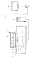
- the observation apparatus 1 includes a housing 5 in which a container 3 containing a sample X can be placed on an upper surface 5a, a light source unit 7 housed in the housing 5, The imaging unit 9 and the focus adjustment unit 11, the control unit 13 that controls the imaging unit 9 and the focus adjustment unit 11, the display unit 15 that displays an image acquired by the imaging unit 9, and an instruction to be sent to the control unit 13 And an operation unit 17 to be input.
- the housing 5 is formed in, for example, a rectangular parallelepiped with minimal unevenness on the outer surface. With such an outer shape, wiping sterilization with 70% ethanol or the like can be facilitated with respect to the outer surface of the housing 5.
- a glass window (transmission window) 5 b capable of transmitting illumination light is provided on the upper surface 5 a of the housing 5 so as to cover the light source unit 7 and the imaging unit 9.
- the casing 5 is formed of a material having UV resistance such as metal except for the glass window 5b.
- a material having UV resistance such as metal except for the glass window 5b.
- the housing 5 may be formed of a material resistant to hydrogen peroxide gas such as stainless steel or anodized.
- the gap at the boundary of the glass window 5b on the upper surface 5a of the housing 5 and the gap such as the hole through which the wiring passes may be sealed with a material having resistance to hydrogen peroxide gas such as silicon. By doing in this way, it can respond to hydrogen peroxide gas sterilization.
- the upper surface 5a of the housing 5 is arranged substantially horizontally. By disposing the upper surface 5a substantially horizontally, the upper surface 5a of the housing 5 can be used as a work table when not observing.
- the glass window 5b provided on the upper surface 5a has a larger area than the container 3, and the container 3 can be placed on the glass window 5b.
- the container 3 is, for example, a cell culture flask having a top plate 3a, and is made of an optically transparent resin as a whole.
- the light source unit 7 includes a single LED light source 19 that is disposed so as to face the glass window 5b while being shifted in a direction intersecting the optical axis of the imaging unit 9.
- the LED light source 19 emits illumination light obliquely upward and transmits the glass window 5b and the bottom surface 3b of the container 3 from bottom to top, and then reflects the illumination light on the top plate 3a of the container 3 so that the container 3
- the illumination light is irradiated to the sample X in 3 obliquely from above.
- the LED light source 19 emits illumination light having a wavelength equal to or greater than the red wavelength, for example. By doing in this way, the phototoxicity to the sample X can be reduced.
- the imaging unit 9 includes an objective lens 21 disposed below the glass window 5b so as to face the glass window 5b, and a camera (camera unit) 23 that captures light collected by the objective lens 21.
- the objective lens 21 transmits the sample X from the top to the bottom, and transmits the glass window 5b from the top to the bottom.
- the transmitted light incident inside is condensed.
- the focus adjustment unit 11 can adjust the focus state of the objective lens 21 with respect to the sample X in the container 3 under the control of the control unit 13.
- the control unit 13 controls the focus adjustment unit 11 so that the focal point of the objective lens 21 coincides with the sample X in the container 3, and automatically controls the exposure time and gain of the camera 23.
- the focus adjustment unit 11 is controlled by the control unit 13, and the focus of the objective lens 21 is made to coincide with the sample X in the container 3 according to the type of the container 3. It is like that.
- control unit 13 can display an image acquired by the camera 23 on the display unit 15 and can store a still image and a moving image.
- the control unit 13 stores the image, the acquired still image and moving image can be left.
- control unit 13 can process the image to remove unevenness in brightness and enhance the contrast. Thereby, the visibility of the sample X can be improved. Further, the control unit 13 can analyze the image and count the number of samples X. Thereby, the quantitative analysis of the sample X can be performed.
- the display unit 15 is a monitor such as a liquid crystal. By using a monitor such as a liquid crystal, the image of the sample X can be displayed with good image quality.
- the operation unit 17 is, for example, a mouse having buttons, a dial, a wheel, and the like, and can be operated by a user by hand. Thereby, an accurate operation becomes possible.
- the observation apparatus 1 configured as described above will be described.
- the sample X is accommodated in the container 3, the top plate 3a is closed, and the container is closed. 3 is placed in a state where the bottom surface 3b is on the lower side, and the sample X is adhered to the bottom surface 3b, and then the container 3 is placed on the glass window 5b on the top surface 5a of the housing 5.
- the LED light source 19 is operated to generate illumination light.
- the illumination light emitted from the LED light source 19 is transmitted from the outside in the radial direction of the objective lens 21 through the glass window 5b on the upper surface 5a of the housing 5 and the bottom surface 3b of the container 3 from the bottom to the top. Reflected on the inner surface of the plate 3a, the sample X is irradiated obliquely from above.
- the transmitted light that has passed through the sample X passes through the bottom surface 3b of the container 3 and the glass window 5b of the housing 5 from top to bottom, and the objective lens in the housing 5 21 is incident.
- the illumination light is refracted and scattered by the shape and refractive index of the sample X, or is attenuated by the transmittance of the sample X, thereby becoming transmitted light carrying the information of the sample X by the objective lens 21.
- the light is condensed and photographed by the camera 23.
- the image of the sample X acquired by the camera 23 is sent to the display unit 15 by the control unit 13 and displayed.
- the light source unit 7 and the imaging unit 9 are accommodated in the housing 5 on which the container 3 is placed, so that the space is limited such as a clean bench. Even when used, it is possible to prevent the light source unit 7 and the imaging unit 9 from interfering with work.
- the LED light source 19 and the imaging unit 9 are disposed below the sample X, compared with a transmitted light observation device that conventionally has disposed the light source unit and the imaging unit on both sides of the sample, Since the LED light source 19 and the imaging unit 9 are concentrated only on one side of the sample X, the casing 5 can be thinned. Thereby, the working efficiency in the limited space can be improved.
- the light source unit 7 may include a diffusion plate (not shown) that diffuses the illumination light emitted from the LED light source 19.
- the diffusion plate is disposed between the LED light source 19 and the glass window 5b of the housing 5, for example.
- the light source unit 7 includes the single LED light source 19.
- the light source unit 7 is arranged around the objective lens 21. It is good also as providing the some LED light source 19 arrange
- the sample X can be illuminated only from a specific direction in the circumferential direction.
- Illumination light with reduced illumination unevenness by simultaneously turning on the LED light sources 19 arranged in two or more directions in the circumferential direction of the objective lens 21, in particular, in an axially symmetric direction with respect to the optical axis of the objective lens 21. Can be irradiated to the sample.
- two LED light sources 19 have been illustrated and described in FIG. 2, the number of LED light sources 19 may be three or more.
- a plurality of LED light sources 19 may be arranged at intervals in the radial direction of the objective lens 21 as well as in the circumferential direction of the objective lens 21.
- the specific LED light source 19 may be turned on independently under the control of the control unit 13. For example, by turning on only the LED light sources 19 at different positions in the radial direction of the objective lens 21, the angle of the illumination light applied to the sample X from obliquely above can be switched.
- the illumination light is emitted by switching the plurality of LED light sources 19. Instead, the illumination light is disposed above the LED light source 19 to shield the illumination light from the LED light source 19. It is good also as employ
- the light shielding member 25 is configured to transmit the transmitted light that has been reflected by the inner surface of the top plate 3 a of the container 3 and transmitted through the sample X.
- a transmission hole 25b for transmitting is provided.
- a plurality of LED light sources 19 may be adopted as the light source unit 7 as in the first modified example, but the function of switching the light emission position of the illumination light is unnecessary, and a wider range than the opening 25a. If it is a light source which can inject illumination light from, you may employ
- the light shielding member 25 having the circular opening 25a is illustrated, but instead of this, for example, the size of the opening 25a such as the fan-shaped opening 25a or the annular opening 25a, Arbitrary positions, shapes, and numbers can be adopted.
- a band-pass filter that transmits only the wavelength of illumination light between the glass window 5 b of the housing 5 and the tip of the objective lens 21 is used.
- An optical filter 27 may be arranged. By doing so, the optical filter 27 prevents external light such as light from the fluorescent lamp of the clean bench from entering the objective lens 21, and can reduce deterioration of image quality due to the influence of external light. it can.
- the optical filter 27 only needs to be able to remove external light entering the camera 23.
- the optical filter 27 may be provided inside the objective lens 21 instead of outside the objective lens 21. It is good also as providing between cameras 23.
- the display unit 15 such as a monitor such as a liquid crystal is illustrated as the display unit.
- a projector that projects an image may be employed as the display unit. Good. By doing in this way, the space which arrange
- the projector can project an image to a position where the user can easily see the posture while working, such as a wall directly facing the user with the observation apparatus 1 interposed therebetween, and work efficiency can be improved.
- a HUD Head-Up Display
- displays an image in the user's field of view may be employed as the display unit. In this way, the user can always work while confirming the image regardless of the direction the user is facing.
- an operation unit 29 such as a foot switch operated by a user with a foot may be adopted.
- an operation unit 29 such as a foot switch may be employed instead of the operation unit 17 such as a mouse, or the operation unit 17 may be employed instead of the operation unit 29.
- an input interface using push buttons such as a keyboard or a push button type remote controller may be employed.
- a notebook PC (Personal Computer) 31 in which the control unit and the display unit are integrated is adopted. It is good. In this way, the image data acquired by the camera 23 can be used as it is for advanced analysis and work by the notebook PC 31.
- a control unit 33 that is converted into an electronic board and built in the housing 5 may be employed. By doing so, the configuration of the observation apparatus 1 can be simplified and power saving can be achieved.
- a display unit 35 and an operation unit 37 arranged on one surface of the housing 5 may be adopted.
- the housing 5 has a space for arranging the display unit 35 and the operation unit 37 in addition to the glass window 5b on the upper surface 5a, and the display unit 35 and the operation unit 37 are arranged on the upper surface 5a of the housing 5. It is good. Furthermore, it is good also as employ
- the configuration in which the housing 5 and the control unit 33, the display unit 35, and the operation unit 37 are all integrated is illustrated.
- the integrated housing 5, the control unit 33, and the operation unit 37 are combined.
- a separate display unit 15 may be employed, or an integrated housing 5, control unit 33, display unit 35, and separate operation units 17 and 29 may be employed. Good.
- the control unit 33 built in the housing 5 may perform transmission and reception with the display unit 15 and the operation unit 29 by wireless communication.
- the camera 23, the focus adjustment unit 11, and the control unit 33 may be battery driven.
- Still image data and moving image data acquired by the camera 23 may be transmitted to another PC 39 or the network 41 by wireless communication by the control unit 33 and stored on another PC 39 or the network 41. Good. By doing so, wiring is eliminated and convenience can be improved.
- a control unit (image aggregation unit) 34 may be provided.
- the other control unit 34 may be connected to one or a plurality of other observation devices 2, a network (external recording medium) 41, any other PC 39, or the like by wire or wireless. . Further, the other control unit 34 receives still image data or moving image image data acquired by the observation device 1 or another observation device 2 according to the present embodiment from the observation device 1 or another observation device 2. The data may be transmitted to the network 41 and stored on the network 41.
- the other control unit 34 functions as a hub (concentrator), aggregates image data from the observation apparatus 1 together with image data from another observation apparatus 2, and aggregates them on the network 41.
- the user can send an instruction or request from any other PC 39 to the network 41 to view the image data.
- the sample X to be observed by the observation apparatus 1 can be observed while being compared with the sample of another observation apparatus 2.
- the operation units 17 and 29 are not employed, and an instruction from the user may be sent to the control unit 33 and the other control unit 34 by the operation unit 37 disposed on one surface of the housing 5.
- the operation unit 37 and the operation units 17 and 29 arranged outside the housing 5 may be used together to send an instruction from the user to the control unit 33 and the other control unit 34.
- FIG. 10 shows an example in which the operation unit 37 and the operation unit 29 are used together.
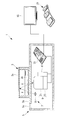
- the observation apparatus 51 according to the present embodiment is different from the observation apparatus 1 according to the first embodiment in that a reflection member 53 is provided above the container 3.
- a reflection member 53 is provided above the container 3.
- the reflecting member 53 is disposed so as to cover the container 3 on the glass window 5 b so as to face the glass window 5 b, and the illumination light transmitted from the light source unit 7 through the glass window 5 b from the bottom to the top is stored in the container 3. It reflects toward the sample X inside.
- the reflecting member 53 for example, glass, resin, a mirror, or the like is used.
- the reflecting member 53 is configured to be retractable from above the container 3. During observation, the reflective member 53 is disposed above the container 3, and after observation, the reflective member 53 is retracted from above the container 3, so that the reflective member 53 is used when the upper surface 5 a of the housing 5 is used as a work table. Can be prevented from interfering with work.
- the container 3 may be a container having a removable top plate 3c such as a petri dish and may be observed with the top plate 3c removed.
- the observation apparatus 51 configured as described above will be described.
- the container 3 containing the sample X is placed on the glass window 5b of the housing 5, and then the container The reflecting member 53 is disposed above the third member. Then, illumination light is generated from the LED light source 19.
- the illumination light emitted from the LED light source 19 passes through the glass window 5b on the upper surface 5a of the housing 5, the bottom surface 3b of the container 3 and the top plate 3c from the bottom to the top, and is then reflected by the reflecting member 53 to be stored in the container. 3 is transmitted through the top plate 3c, and the sample X is irradiated obliquely from above.
- the transmitted light that has passed through the sample X passes through the bottom surface 3 b of the container 3 and the glass window 5 b of the housing 5 from the top to the bottom, enters the housing 5, is condensed on the objective lens 21, and is collected by the camera 23. Taken.
- the illumination light from the LED light source 19 is reflected not by the top plate 3c of the container 3 but by the reflecting member 53 and irradiated to the sample X, so that the illumination condition depends on the type of the container 3
- the image quality can be stabilized without changing.
- control units 13 and 33, the display units 15 and 35, the operation units 17, 29 and 37, the notebook PC 31 and other control units 34 are appropriately combined. To adopt.
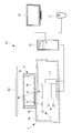
- the observation apparatus 61 according to the present embodiment is the same as the first embodiment in that the housing 5 is embedded in the work floor 63a of the clean bench 63 and is formed integrally with the work floor 63a.
- the observation device 1 is different from the observation device 51 according to the second embodiment.
- the same reference numerals are given to portions having the same configurations as those of the observation device 1 according to the first embodiment and the observation device 51 according to the second embodiment described above, and the description thereof is omitted.
- the housing 5 may be arranged such that the upper surface 5a is flush with the work floor 63a. By doing in this way, the housing
- observation method of the sample X using the observation apparatus 61 configured as described above is the same as that of the first embodiment except that it is operated in the clean bench 63, the description thereof is omitted.
- an observation function can be added to the clean bench 63 without sacrificing the work space in the clean bench 63.
- the reflection member 53 may be employed as in the second embodiment, and the illumination light from the light source unit 7 may be irradiated onto the sample X from above by the reflection member 53.
- the reflecting member 53 is configured to be retractable from above the sample X, the work space in the clean bench 63 need not be sacrificed.
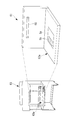
- the sample X may be observed using illumination light from the bench illumination (light source) 65 of the clean bench 63. Good.
- the controller 13 removes flickers (flicker) derived from a fluorescent lamp in the image sent from the camera 23 by image processing. In this way, the illumination conditions do not change depending on the shooting environment, and the image quality can be stabilized.
- an optical filter 27 that transmits only the wavelength of the illumination light is disposed between the glass window 5b and the objective lens 21, inside the objective lens 21, or between the objective lens 21 and the camera 23. It is good as well.
- the configuration in which the housing 5 is embedded in the work floor 63a has been described as an example.
- the housing 5 may be placed on the work floor 63a.
- the light source unit 7 and the imaging unit 9 are accommodated in the housing 5 on which the container 3 is placed, the light source unit 7 and the imaging unit can be used even in a limited work space of the clean bench 63. 9 can be prevented from interfering with work, and work efficiency can be improved.
- control units 13 and 33, the display units 15 and 35, the operation units 17, 29 and 37, the notebook PC 31 and other control units 34 are appropriately combined. To adopt.
- a PC can be adopted as the control unit 13 and the other control unit 34.
- a control circuit can be employed as the control unit 33.
Abstract
In order to improve work efficiency without interfering with work even when used in a limited space such as on a clean bench, an observation device (1) according to the present invention is provided with: a housing (5) having on the upper surface thereof a glass window (5b) on which a container (3) containing a sample (X) is placed and through which illumination light can be transmitted; and an imaging unit (9) which is contained in the housing (5) and which photographs the transmitted light, the transmitted light being the illumination light transmitted through the sample (X) from above and through the glass window (5b) and made incident into the housing (5).
Description
本発明は、観察装置に関するものである。
The present invention relates to an observation apparatus.
従来、クリーンベンチ内に設置される試料観察用の観察装置が知られている(例えば、特許文献1および特許文献2参照。)。
Conventionally, an observation apparatus for observing a sample installed in a clean bench is known (see, for example, Patent Document 1 and Patent Document 2).
しかしながら、特許文献1,2に記載の観察装置は、支持スタンドにより支持される一般的な倒立型微鏡であり、クリーンベンチ内の限られた作業スペースで使用するには、支持スタンドや撮影光学系等が作業の際に邪魔になるという不都合がある。
However, the observation devices described in Patent Documents 1 and 2 are general inverted microscopes supported by a support stand. For use in a limited work space in a clean bench, the support stand and imaging optics are used. There is an inconvenience that the system or the like gets in the way of work.
本発明は上述した事情に鑑みてなされたものであって、クリーンベンチのような限られたスペースで使用する場合にも、作業の邪魔にならず作業効率を向上することができる観察装置を提供することを目的としている。
The present invention has been made in view of the circumstances described above, and provides an observation apparatus that can improve work efficiency without interfering with work even when used in a limited space such as a clean bench. The purpose is to do.
上記目的を達成するために、本発明は以下の手段を提供する。
本発明の一態様は、試料を収容した容器を載置可能かつ照明光を透過可能な透過窓を上面に有する筐体と、該筐体に収容され、前記照明光が上方から前記試料を透過しかつ前記透過窓を透過して前記筐体内に入射した透過光を撮影する撮像部とを備える観察装置である。 In order to achieve the above object, the present invention provides the following means.
One embodiment of the present invention includes a housing having an upper surface on which a container accommodating a sample can be placed and which can transmit illumination light. The housing is accommodated in the housing, and the illumination light passes through the sample from above. And an imaging unit that photographs the transmitted light that has passed through the transmission window and entered the housing.
本態様によれば、筐体の上面の透過窓上に載置されている容器内の試料に上方から照明光が照射されると、試料を上から下に透過した透過光が透過窓も透過して筐体に入射され、筐体内の撮像部によって撮影される。容器を載置する筐体内に撮像部を収容することで、クリーンベンチのような限られたスペースで使用する場合にも、撮像部が作業の邪魔になるのを抑制し、作業効率を向上することができる。
According to this aspect, when the illumination light is irradiated from above on the sample in the container placed on the transmission window on the upper surface of the housing, the transmitted light transmitted from the top to the bottom is also transmitted through the transmission window. Then, the light enters the case and is photographed by the imaging unit in the case. By housing the imaging unit in the casing on which the container is placed, even when used in a limited space such as a clean bench, the imaging unit is prevented from interfering with work, and work efficiency is improved. be able to.
上記態様においては、前記筐体に収容され、前記試料の下方から上方に向けて前記照明光を射出する光源部を備え、前記撮像部が、前記光源部から射出された前記照明光が前記試料の上方で反射されることにより前記試料および前記透過窓を透過した前記透過光を撮影することとしてもよい。
In the above aspect, the apparatus includes a light source unit that is housed in the housing and emits the illumination light from below to above the sample, and the imaging unit receives the illumination light emitted from the light source unit. It is good also as image | photographing the said transmitted light which permeate | transmitted the said sample and the said permeation | transmission window by being reflected above.
このように構成することで、容器を載置する筐体内に光源部を収容することで、光源部が作業の邪魔になるのを抑制することができる。この場合において、光源部および撮像部の両方を試料の下方に配置することにより、光源部および撮像部を試料を挟んで試料の上方と下方に分けて配置する場合と比較して、装置の高さを低く抑え、筐体を薄型化することができる。これにより、クリーンベンチ内のような限られたスペースで使用する場合においても作業効率を向上することができる。
By configuring in this way, it is possible to prevent the light source unit from interfering with the work by accommodating the light source unit in the casing on which the container is placed. In this case, by arranging both the light source unit and the imaging unit below the sample, the height of the apparatus is higher than when the light source unit and the imaging unit are arranged separately above and below the sample with the sample in between. The thickness can be kept low and the casing can be made thinner. Thereby, even when using it in the limited space like the inside of a clean bench, work efficiency can be improved.
上記態様においては、前記撮像部が、前記透過光を集光する対物レンズを備え、前記光源部が、前記対物レンズの径方向外方から前記試料の上方に前記照明光を射出することとしてもよい。
In the above aspect, the imaging unit may include an objective lens that condenses the transmitted light, and the light source unit may emit the illumination light above the sample from outside in the radial direction of the objective lens. Good.
このように構成することで、試料の下方に配置された対物レンズの径方向外方に配置された光源部から試料の上方に向けて射出された照明光が、試料の上方においては反射されて、対物レンズの光軸に対して斜め上方から試料に入射し、試料を透過した透過光が撮像部により撮影される。試料への入射角度を適切に設定することにより、試料の像に明暗を形成することができ、細胞等の透明な被写体についても見やすい像を取得することができる。
With this configuration, the illumination light emitted toward the upper side of the sample from the light source unit arranged radially outward of the objective lens arranged below the sample is reflected above the sample. The incident light is incident on the sample obliquely from above the optical axis of the objective lens, and transmitted light that has passed through the sample is photographed by the imaging unit. By appropriately setting the incident angle on the sample, light and dark can be formed in the image of the sample, and an easy-to-see image can be obtained even for transparent subjects such as cells.
上記態様においては、前記光源部が、前記対物レンズの径方向に異なる位置から独立して前記照明光を射出可能であってもよい。
このように構成することで、光源部から射出される照明光の径方向位置を異ならせることで、試料の上方に配置された同一の反射面によって反射された反射光の試料への入射角度を変化させることができる。すなわち、対物レンズの径方向の近い位置から射出された照明光の反射光は、光軸に対して小さい角度をなして試料に入射する一方、対物レンズの径方向に遠い位置から射出された照明光の反射光は、光軸に対して大きな角度をなして試料に入射する。 In the above aspect, the light source unit may be capable of emitting the illumination light independently from different positions in the radial direction of the objective lens.
By configuring in this way, by changing the radial position of the illumination light emitted from the light source unit, the incident angle of the reflected light reflected by the same reflecting surface disposed above the sample can be changed. Can be changed. That is, the reflected light of the illumination light emitted from a position close to the radial direction of the objective lens enters the sample at a small angle with respect to the optical axis, while the illumination emitted from a position far from the radial direction of the objective lens The reflected light of the light enters the sample at a large angle with respect to the optical axis.
これにより、対物レンズの取り込み角よりも小さい入射角の場合は、照明ムラの少ない明視野照明とし、また対物レンズの取り込み角よりも大きい入射角の場合は、微細構造が強調される暗視野照明とし、さらに対物レンズの取り込み角と同等の入射角の場合は、試料が立体的に見える偏斜照明とすることができる。
This makes bright field illumination with less illumination unevenness when the incident angle is smaller than the capture angle of the objective lens, and dark field illumination that emphasizes the fine structure when the incident angle is larger than the capture angle of the objective lens. In addition, in the case of an incident angle equivalent to the taking-in angle of the objective lens, oblique illumination in which the sample can be viewed stereoscopically can be obtained.
上記態様においては、前記光源部が、前記対物レンズの周方向に異なる位置から同時に前記照明光を射出可能であってもよい。
このように構成することで、対物レンズの周方向に複数位置から同時に照明光が照射され、照明ムラを低減することができる。 In the above aspect, the light source unit may be capable of emitting the illumination light simultaneously from different positions in the circumferential direction of the objective lens.
By comprising in this way, illumination light can be simultaneously irradiated from multiple positions in the circumferential direction of the objective lens, and illumination unevenness can be reduced.
上記態様においては、前記光源部が、前記対物レンズの周囲に配列され、独立して点灯可能な複数の光源を備えることとしてもよい。
このように構成することで、複数の光源の内のいずれかを点灯させることにより、照明光の周方向位置を決定することができる。そして、点灯させる光源の周方向位置を切り替えることにより、異なる方向から照明された試料の像を撮影することができる。特に、上記偏斜照明の像においては、異なる陰影の付き方の像を撮影することができる。 In the above aspect, the light source unit may include a plurality of light sources that are arranged around the objective lens and can be lit independently.
By comprising in this way, the circumferential direction position of illumination light can be determined by lighting any one of several light sources. And the image of the sample illuminated from a different direction can be image | photographed by switching the circumferential direction position of the light source to light. In particular, in the oblique illumination image, it is possible to photograph images with different shades.
上記態様においては、前記光源部が、前記試料の下方に配置される光源と、該光源からの照明光のうち、特定の径方向位置の前記照明光のみを透過させる開口部を有する遮光部材とを備えることとしてもよい。
In the above aspect, the light source unit includes a light source disposed below the sample, and a light shielding member having an opening that transmits only the illumination light at a specific radial position among illumination light from the light source; It is good also as providing.
このように構成することで、光源からの照明光が遮光部材によって遮られ、開口部を通過する照明光のみが、試料の上方において反射されて試料に入射させられる。したがって、光源の点灯位置を切り替えることなく、遮光部材の開口部の位置を調節することにより、試料に入射させる反射光の方向あるいは角度を変化させることができる。
With this configuration, the illumination light from the light source is blocked by the light shielding member, and only the illumination light passing through the opening is reflected above the sample and is incident on the sample. Therefore, the direction or angle of the reflected light incident on the sample can be changed by adjusting the position of the opening of the light shielding member without switching the lighting position of the light source.
上記態様においては、前記撮像部が、前記対物レンズにより集光された前記照明光を受光し前記試料の像を取得するカメラ部と、前記照明光の波長のみを透過する光学フィルタとを備え、前記対物レンズが、前記透過窓を挟んで前記試料と対向して配置され、前記光学フィルタが、前記透過窓と前記対物レンズとの間、前記対物レンズ内部、前記対物レンズと前記カメラ部との間のいずれかに配置されていることとしてもよい。
In the above aspect, the imaging unit includes a camera unit that receives the illumination light collected by the objective lens and acquires an image of the sample, and an optical filter that transmits only the wavelength of the illumination light. The objective lens is disposed to face the sample with the transmission window interposed therebetween, and the optical filter is disposed between the transmission window and the objective lens, inside the objective lens, between the objective lens and the camera unit. It is good also as arrange | positioning at either.
このように構成することで、光学フィルタにより、カメラ部に入射しようとする照明光以外の光が遮断されるので、照明光以外の光の影響による画質の劣化を低減することができる。
With this configuration, the optical filter blocks light other than illumination light that is about to enter the camera unit, so that deterioration in image quality due to the influence of light other than illumination light can be reduced.
上記態様においては、前記光源部が、前記照明光を拡散させる拡散板を備えることとしてもよい。
このように構成することで、拡散板によって均一に拡散された照明光を試料に照射させることができる。 In the above aspect, the light source unit may include a diffusion plate that diffuses the illumination light.
By comprising in this way, the illumination light uniformly diffused by the diffusion plate can be irradiated to the sample.
このように構成することで、拡散板によって均一に拡散された照明光を試料に照射させることができる。 In the above aspect, the light source unit may include a diffusion plate that diffuses the illumination light.
By comprising in this way, the illumination light uniformly diffused by the diffusion plate can be irradiated to the sample.
上記態様においては、前記照明光が前記容器の天板内面によって反射されることとしてもよい。
このように構成することで、内部に試料を収容した天板を有する容器を光源部および撮像部の上方に配置するだけで、光源部から射出された照明光を容器の天板内面において反射させ、容器内の試料に照射させることができる。 In the above aspect, the illumination light may be reflected by the inner surface of the top plate of the container.
With this configuration, the illumination light emitted from the light source unit is reflected on the inner surface of the top plate of the container simply by placing the container having the top plate containing the sample inside the light source unit and the imaging unit. The sample in the container can be irradiated.
上記態様においては、前記照明光が、前記試料の上方に配置された反射部材によって反射されることとしてもよい。
このように構成することで、シャーレのように天板を取り外した状態で観察する可能性のある容器や細胞培養バッグ内に収容された試料を観察する場合において、試料の上方に反射部材を配置することにより、光源部から射出された照明光を反射部材において反射させ、容器内の試料に照射させることができる。 In the above aspect, the illumination light may be reflected by a reflecting member disposed above the sample.
With this configuration, when observing a sample stored in a container or cell culture bag that may be observed with the top plate removed, such as a petri dish, a reflective member is placed above the sample. By doing so, it is possible to reflect the illumination light emitted from the light source unit on the reflecting member and irradiate the sample in the container.
上記態様においては、前記試料が溶液内に浸されており、前記照明光が前記溶液の上方の液面によって反射されることとしてもよい。
このように構成することで、天板を有しない容器や、反射部材を配置できない容器内に収容された試料を観察する場合において、光源部から射出された照明光を溶液の液面において反射させ、容器内の試料に照射させることができる。 In the above aspect, the sample may be immersed in the solution, and the illumination light may be reflected by the liquid surface above the solution.
With this configuration, when observing a sample stored in a container that does not have a top plate or a container in which no reflecting member can be arranged, the illumination light emitted from the light source unit is reflected on the liquid surface of the solution. The sample in the container can be irradiated.
上記態様においては、前記撮像部が、前記筐体外に配置されている光源から射出された前記照明光が上方から前記試料に照射されることにより該試料および前記透過窓を透過した前記透過光を撮影することとしてもよい。
このように構成することで、筐体内に光源を収容しない分だけ筐体を薄型化および小型化することができる。 In the above aspect, the imaging unit emits the transmitted light transmitted through the sample and the transmission window by irradiating the sample with the illumination light emitted from the light source disposed outside the casing. It is good also as photographing.
With this configuration, the casing can be reduced in thickness and size by the amount that does not accommodate the light source in the casing.
上記態様においては、前記撮像部が、前記透過光を集光する対物レンズと、前記対物レンズにより集光された前記照明光を受光し前記試料の像を取得するカメラ部と、前記照明光の波長のみを透過する光学フィルタとを備え、前記対物レンズが、前記透過窓を挟んで前記試料と対向して配置され、光学フィルタが、前記透過窓と前記対物レンズとの間、前記対物レンズ内部、前記対物レンズと前記カメラ部との間のいずれかに配置されていることとしてもよい。
In the above aspect, the imaging unit collects the transmitted light, an objective lens that collects the transmitted light, a camera unit that receives the illumination light collected by the objective lens and acquires an image of the sample, and the illumination light An optical filter that transmits only the wavelength, the objective lens is disposed to face the sample with the transmission window interposed therebetween, and the optical filter is disposed between the transmission window and the objective lens, and inside the objective lens. It may be arranged between the objective lens and the camera unit.
このように構成することで、光学フィルタにより、カメラ部に入射しようとする照明光以外の光が遮断されるので、照明光以外の光の影響による画質の劣化を低減することができる。
With this configuration, the optical filter blocks light other than illumination light that is about to enter the camera unit, so that deterioration in image quality due to the influence of light other than illumination light can be reduced.
上記態様においては、前記撮像部により取得された前記試料の画像を表示する表示部を備えることとしてもよい。
このように構成することで、ユーザは表示部により表示される画像を見て試料を観察することができる。 In the said aspect, it is good also as providing the display part which displays the image of the said sample acquired by the said imaging part.
With this configuration, the user can observe the sample by looking at the image displayed on the display unit.
上記態様においては、前記表示部が前記筐体の一表面に配置されていることとしてもよい。
このように構成することで、筐体とは別に表示部を配置するスペースを省くことができる。 In the above aspect, the display unit may be disposed on one surface of the casing.
With this configuration, a space for arranging the display unit separately from the housing can be saved.
このように構成することで、筐体とは別に表示部を配置するスペースを省くことができる。 In the above aspect, the display unit may be disposed on one surface of the casing.
With this configuration, a space for arranging the display unit separately from the housing can be saved.
上記態様においては、前記表示部が前記画像を投影するプロジェクタであってもよい。
このように構成することで、筐体とは別に表示部を配置するスペースを省くことができるとともに、プロジェクタにより、作業をしながらの姿勢で見やすい位置に画像を投影して作業効率を向上することができる。 In the above aspect, the display unit may be a projector that projects the image.
With this configuration, it is possible to save a space for arranging the display unit separately from the housing, and to improve work efficiency by projecting an image to a position that is easy to see with the posture while working. Can do.
上記態様においては、前記試料に対する前記撮像部の合焦状態を調整するフォーカス調整部と、前記撮像部の焦点を前記試料に一致させるように前記フォーカス調整部を制御する制御部とを備えることとしてもよい。
In the above aspect, a focus adjustment unit that adjusts the in-focus state of the imaging unit with respect to the sample, and a control unit that controls the focus adjustment unit so that the focus of the imaging unit coincides with the sample. Also good.
このように構成することで、制御部によりフォーカス調整部を介して自動的に対物レンズの焦点を合わせることができる。手動による作業を省くことで、クリーンベンチ内のような限られたスペースで使用する場合により有効となる。
With this configuration, the objective lens can be automatically focused by the control unit via the focus adjustment unit. By eliminating manual work, it becomes more effective when used in a limited space such as in a clean bench.
上記態様においては、前記制御部の少なくとも一部が前記筐体に内包されていることとしてもよい。
このように構成することで、制御部が筐体に内包される分だけ、筐体外のスペースを確保することができる。 In the above aspect, at least a part of the control unit may be included in the housing.
By comprising in this way, the space outside a housing | casing can be ensured by the part which a control part is included in a housing | casing.
このように構成することで、制御部が筐体に内包される分だけ、筐体外のスペースを確保することができる。 In the above aspect, at least a part of the control unit may be included in the housing.
By comprising in this way, the space outside a housing | casing can be ensured by the part which a control part is included in a housing | casing.
上記態様においては、前記制御部に送る指示をユーザに入力させる操作部を備えることとしてもよい。
このように構成することで、ユーザは操作部に指示を入力するだけで、所望の操作を実行することができる。 In the said aspect, it is good also as providing the operation part which makes a user input the instruction | indication sent to the said control part.
With this configuration, the user can execute a desired operation only by inputting an instruction to the operation unit.
上記態様においては、前記操作部がフットスイッチであってもよい。
このように構成することで、ユーザは手で他の作業をしながら操作部に指示を入力することができ、作業効率を向上することができる。 In the above aspect, the operation unit may be a foot switch.
With this configuration, the user can input an instruction to the operation unit while performing other work by hand, and work efficiency can be improved.
このように構成することで、ユーザは手で他の作業をしながら操作部に指示を入力することができ、作業効率を向上することができる。 In the above aspect, the operation unit may be a foot switch.
With this configuration, the user can input an instruction to the operation unit while performing other work by hand, and work efficiency can be improved.
上記態様においては、前記操作部が前記筐体の一表面に配置されていることとしてもよい。
このように構成することで、筐体とは別に操作部を配置するスペースを省略することができる。 In the above aspect, the operation unit may be disposed on one surface of the casing.
By comprising in this way, the space which arrange | positions an operation part separately from a housing | casing can be abbreviate | omitted.
このように構成することで、筐体とは別に操作部を配置するスペースを省略することができる。 In the above aspect, the operation unit may be disposed on one surface of the casing.
By comprising in this way, the space which arrange | positions an operation part separately from a housing | casing can be abbreviate | omitted.
上記態様においては、前記筐体の前記上面が略水平に配置されることとしてもよい。
このように構成することで、非観察時に筐体の上面を作業台として使用でき、作業スペースを有効に確保することができる。 In the said aspect, the said upper surface of the said housing | casing is good also as arrange | positioning substantially horizontal.
With this configuration, the upper surface of the housing can be used as a work table when not observing, and a work space can be effectively secured.
上記態様においては、前記撮像部により取得された前記試料の画像を他の観察装置において取得された画像とともに集約して外部の記録媒体に保存させる画像集約部を備えることとしてもよい。
In the above aspect, an image aggregating unit that aggregates the sample image acquired by the imaging unit together with the image acquired by another observation apparatus and stores the image in an external recording medium may be provided.
このように構成することで、画像集約部により、撮像部により取得された試料の画像と他の観察装置により取得された画像と一緒に外部の記録媒体において容易に管理することができる。したがって、外部の記録媒体からこれらの画像を読み出せば、この観察装置により観察しようとする試料を他の観察装置の試料と一緒に比較しながら観察することができる。
With this configuration, the image aggregating unit can easily manage the sample image acquired by the imaging unit and the image acquired by another observation apparatus in an external recording medium. Therefore, if these images are read from an external recording medium, the sample to be observed by this observation apparatus can be observed while being compared with the samples of other observation apparatuses.
本発明に係る顕微鏡によれば、クリーンベンチのような限られたスペースで使用する場合にも、作業の邪魔にならず作業効率を向上することができるという効果を奏する。
According to the microscope of the present invention, even when used in a limited space such as a clean bench, the working efficiency can be improved without interfering with the work.
〔第1実施形態〕
本実施形態に係る観察装置について図面を参照して以下に説明する。
本実施形態に係る観察装置1は、図1に示されるように、試料Xを収容した容器3を上面5aに載置可能な筐体5と、筐体5内に収容された光源部7、撮像部9およびフォーカス調整部11と、撮像部9およびフォーカス調整部11を制御する制御部13と、撮像部9により取得された画像を表示する表示部15と、制御部13に送る指示をユーザに入力させる操作部17とを備えている。 [First Embodiment]
The observation apparatus according to the present embodiment will be described below with reference to the drawings.
As shown in FIG. 1, theobservation apparatus 1 according to the present embodiment includes a housing 5 in which a container 3 containing a sample X can be placed on an upper surface 5a, a light source unit 7 housed in the housing 5, The imaging unit 9 and the focus adjustment unit 11, the control unit 13 that controls the imaging unit 9 and the focus adjustment unit 11, the display unit 15 that displays an image acquired by the imaging unit 9, and an instruction to be sent to the control unit 13 And an operation unit 17 to be input.
本実施形態に係る観察装置について図面を参照して以下に説明する。
本実施形態に係る観察装置1は、図1に示されるように、試料Xを収容した容器3を上面5aに載置可能な筐体5と、筐体5内に収容された光源部7、撮像部9およびフォーカス調整部11と、撮像部9およびフォーカス調整部11を制御する制御部13と、撮像部9により取得された画像を表示する表示部15と、制御部13に送る指示をユーザに入力させる操作部17とを備えている。 [First Embodiment]
The observation apparatus according to the present embodiment will be described below with reference to the drawings.
As shown in FIG. 1, the
筐体5は、例えば、外面に凹凸が最小限の直方体に形成されている。このような外形により、筐体5の外面に対して70%エタノール等による拭き滅菌を容易にすることができる。筐体5の上面5aには、照明光を透過可能なガラス窓(透過窓)5bが光源部7および撮像部9の上方を覆うように設けられている。
The housing 5 is formed in, for example, a rectangular parallelepiped with minimal unevenness on the outer surface. With such an outer shape, wiping sterilization with 70% ethanol or the like can be facilitated with respect to the outer surface of the housing 5. A glass window (transmission window) 5 b capable of transmitting illumination light is provided on the upper surface 5 a of the housing 5 so as to cover the light source unit 7 and the imaging unit 9.
また、筐体5は、ガラス窓5bを除き、金属等のUV耐性を有する材質により形成されている。このような材質により、筐体5はクリーンベンチのUV殺菌灯による滅菌が可能になる。例えば、ステンレス、アルマイト等の過酸化水素ガス耐性の材質により筐体5を形成することとしてもよい。この場合、筐体5の上面5aにおけるガラス窓5bの境界の隙間や配線を通す穴等の隙間は、シリコン等の過酸化水素ガス耐性を有する材質でシーリングすることとすればよい。このようにすることで、過酸化水素ガス滅菌に対応することができる。
The casing 5 is formed of a material having UV resistance such as metal except for the glass window 5b. Such a material enables the housing 5 to be sterilized with a clean bench UV germicidal lamp. For example, the housing 5 may be formed of a material resistant to hydrogen peroxide gas such as stainless steel or anodized. In this case, the gap at the boundary of the glass window 5b on the upper surface 5a of the housing 5 and the gap such as the hole through which the wiring passes may be sealed with a material having resistance to hydrogen peroxide gas such as silicon. By doing in this way, it can respond to hydrogen peroxide gas sterilization.
また、筐体5は、上面5aが略水平に配置されるようになっている。上面5aを略水平に配置することで、非観察時に筐体5の上面5aを作業台として使用することができる。上面5aに設けられているガラス窓5bは容器3よりも大きい面積を有しており、ガラス窓5b上に容器3を載置することができるようになっている。
Further, the upper surface 5a of the housing 5 is arranged substantially horizontally. By disposing the upper surface 5a substantially horizontally, the upper surface 5a of the housing 5 can be used as a work table when not observing. The glass window 5b provided on the upper surface 5a has a larger area than the container 3, and the container 3 can be placed on the glass window 5b.
容器3は、例えば、天板3aを有する細胞培養フラスコであり、全体的に光学的に透明な樹脂により構成されている。
The container 3 is, for example, a cell culture flask having a top plate 3a, and is made of an optically transparent resin as a whole.
光源部7は、撮像部9の光軸に対して交差する方向に位置をずらして、ガラス窓5bに対向して配置された単一のLED光源19を備えている。LED光源19は、斜め上方に照明光を射出してガラス窓5bおよび容器3の底面3bを下から上に向かって透過させた後、容器3の天板3aにおいて照明光を反射させて、容器3内の試料Xに対して斜め上方から照明光を照射するようになっている。LED光源19は、例えば、赤色の波長以上の波長の照明光を射出するようになっている。このようにすることで、試料Xへの光毒性を低減することができる。
The light source unit 7 includes a single LED light source 19 that is disposed so as to face the glass window 5b while being shifted in a direction intersecting the optical axis of the imaging unit 9. The LED light source 19 emits illumination light obliquely upward and transmits the glass window 5b and the bottom surface 3b of the container 3 from bottom to top, and then reflects the illumination light on the top plate 3a of the container 3 so that the container 3 The illumination light is irradiated to the sample X in 3 obliquely from above. The LED light source 19 emits illumination light having a wavelength equal to or greater than the red wavelength, for example. By doing in this way, the phototoxicity to the sample X can be reduced.
撮像部9は、ガラス窓5bの下方にガラス窓5bに対向して配置される対物レンズ21と、対物レンズ21により集光された光を撮影するカメラ(カメラ部)23とを備えている。対物レンズ21は、LED光源19からの照明光が上方から試料Xに照射されることにより、試料Xを上から下に透過し、かつ、ガラス窓5bを上から下に透過して筐体5内に入射する透過光を集光するようになっている。
The imaging unit 9 includes an objective lens 21 disposed below the glass window 5b so as to face the glass window 5b, and a camera (camera unit) 23 that captures light collected by the objective lens 21. When the illumination light from the LED light source 19 is irradiated onto the sample X from above, the objective lens 21 transmits the sample X from the top to the bottom, and transmits the glass window 5b from the top to the bottom. The transmitted light incident inside is condensed.
フォーカス調整部11は、制御部13の制御により、容器3内の試料Xに対する対物レンズ21の合焦状態を調整することができるようになっている。
The focus adjustment unit 11 can adjust the focus state of the objective lens 21 with respect to the sample X in the container 3 under the control of the control unit 13.
制御部13は、対物レンズ21の焦点を容器3内の試料Xに一致させるようにフォーカス調整部11を制御したり、カメラ23の露光時間およびゲインを自動制御したりするようになっている。ユーザが操作部17により容器3の種類を指定すると、制御部13によりフォーカス調整部11が制御されて、容器3の種類に合わせて対物レンズ21の焦点が容器3内の試料Xに一致させられるようになっている。
The control unit 13 controls the focus adjustment unit 11 so that the focal point of the objective lens 21 coincides with the sample X in the container 3, and automatically controls the exposure time and gain of the camera 23. When the user designates the type of the container 3 by the operation unit 17, the focus adjustment unit 11 is controlled by the control unit 13, and the focus of the objective lens 21 is made to coincide with the sample X in the container 3 according to the type of the container 3. It is like that.
また、制御部13は、カメラ23により取得された画像を表示部15に表示させたり、静止画像および動画像を保存したりすることができるようになっている。制御部13が画像を保存することで、取得した静止画像および動画像を残しておくことができる。
Further, the control unit 13 can display an image acquired by the camera 23 on the display unit 15 and can store a still image and a moving image. When the control unit 13 stores the image, the acquired still image and moving image can be left.
また、制御部13は、画像を処理して明るさムラを除去したりコントラストを強調したりすることができるようになっている。これにより、試料Xの見やすさを向上することができる。また、制御部13は、画像を解析して試料Xの数を計数することができるようになっている。これにより、試料Xの定量解析を行うことができる。
Further, the control unit 13 can process the image to remove unevenness in brightness and enhance the contrast. Thereby, the visibility of the sample X can be improved. Further, the control unit 13 can analyze the image and count the number of samples X. Thereby, the quantitative analysis of the sample X can be performed.
表示部15は、例えば液晶等のモニタである。液晶等のモニタを用いることで、試料Xの画像を良好な画質で表示することができる。
操作部17は、例えば、ボタン、ダイヤル、ホイール等を有するマウスであり、ユーザが手で操作することができるようになっている。これにより、正確な操作が可能となる。 Thedisplay unit 15 is a monitor such as a liquid crystal. By using a monitor such as a liquid crystal, the image of the sample X can be displayed with good image quality.
Theoperation unit 17 is, for example, a mouse having buttons, a dial, a wheel, and the like, and can be operated by a user by hand. Thereby, an accurate operation becomes possible.
操作部17は、例えば、ボタン、ダイヤル、ホイール等を有するマウスであり、ユーザが手で操作することができるようになっている。これにより、正確な操作が可能となる。 The
The
このように構成された観察装置1の作用について説明する。
本実施形態に係る観察装置1を用いて細胞のように透明な試料Xを観察するには、図1に示されるように、試料Xを容器3内に収容し天板3aを閉めて、容器3を底面3bが下側になる状態で静置し試料Xが底面3bに接着した後、筐体5の上面5aのガラス窓5b上に容器3を載置する。 The operation of theobservation apparatus 1 configured as described above will be described.
In order to observe a transparent sample X like a cell using theobservation apparatus 1 according to the present embodiment, as shown in FIG. 1, the sample X is accommodated in the container 3, the top plate 3a is closed, and the container is closed. 3 is placed in a state where the bottom surface 3b is on the lower side, and the sample X is adhered to the bottom surface 3b, and then the container 3 is placed on the glass window 5b on the top surface 5a of the housing 5.
本実施形態に係る観察装置1を用いて細胞のように透明な試料Xを観察するには、図1に示されるように、試料Xを容器3内に収容し天板3aを閉めて、容器3を底面3bが下側になる状態で静置し試料Xが底面3bに接着した後、筐体5の上面5aのガラス窓5b上に容器3を載置する。 The operation of the
In order to observe a transparent sample X like a cell using the
次いで、LED光源19を作動させて照明光を発生させる。LED光源19から発せられた照明光は、対物レンズ21の径方向外方から筐体5の上面5aのガラス窓5bおよび容器3の底面3bを下から上に向かって透過し、容器3の天板3a内面において反射されて、試料Xに対して斜め上方から照射される。
Next, the LED light source 19 is operated to generate illumination light. The illumination light emitted from the LED light source 19 is transmitted from the outside in the radial direction of the objective lens 21 through the glass window 5b on the upper surface 5a of the housing 5 and the bottom surface 3b of the container 3 from the bottom to the top. Reflected on the inner surface of the plate 3a, the sample X is irradiated obliquely from above.
試料Xに照射された照明光の内、試料Xを透過した透過光は、容器3の底面3bおよび筐体5のガラス窓5bを上から下に向かって透過し、筐体5内の対物レンズ21に入射する。この際、照明光は試料Xの形状や屈折率によって屈折、散乱され、あるいは、試料Xの透過率によって減光されることで、試料Xの情報を載せた透過光となって対物レンズ21により集光されてカメラ23により撮影される。カメラ23により取得された試料Xの画像は、制御部13により表示部15に送られて表示される。
Of the illumination light irradiated to the sample X, the transmitted light that has passed through the sample X passes through the bottom surface 3b of the container 3 and the glass window 5b of the housing 5 from top to bottom, and the objective lens in the housing 5 21 is incident. At this time, the illumination light is refracted and scattered by the shape and refractive index of the sample X, or is attenuated by the transmittance of the sample X, thereby becoming transmitted light carrying the information of the sample X by the objective lens 21. The light is condensed and photographed by the camera 23. The image of the sample X acquired by the camera 23 is sent to the display unit 15 by the control unit 13 and displayed.
このように、本実施形態に係る観察装置1によれば、容器3を載置する筐体5内に光源部7および撮像部9を収容することで、クリーンベンチのような限られたスペースで使用する場合にも、これら光源部7および撮像部9が作業の邪魔になるのを抑制することができる。その上、試料Xの下方にLED光源19および撮像部9を配置しているので、従来、試料を挟んだ両側に光源部と撮像部とを配置していた透過光の観察装置と比較すると、試料Xの片側のみにLED光源19および撮像部9が集約される分だけ、筐体5を薄型化することができる。これにより、限られたスペースでの作業効率を向上することができる。
As described above, according to the observation device 1 according to the present embodiment, the light source unit 7 and the imaging unit 9 are accommodated in the housing 5 on which the container 3 is placed, so that the space is limited such as a clean bench. Even when used, it is possible to prevent the light source unit 7 and the imaging unit 9 from interfering with work. In addition, since the LED light source 19 and the imaging unit 9 are disposed below the sample X, compared with a transmitted light observation device that conventionally has disposed the light source unit and the imaging unit on both sides of the sample, Since the LED light source 19 and the imaging unit 9 are concentrated only on one side of the sample X, the casing 5 can be thinned. Thereby, the working efficiency in the limited space can be improved.
本実施形態においては、光源部7が、LED光源19から発せられた照明光を拡散させる拡散板(図示略)を備えることとしてもよい。拡散板は、例えばLED光源19と筐体5のガラス窓5bとの間に配置されている。このようにすることで、LED光源19から発せられた照明光が拡散板により均一に拡散されるので、照明ムラの少ない均一な強度の照明光を試料Xに照射することができる。
In the present embodiment, the light source unit 7 may include a diffusion plate (not shown) that diffuses the illumination light emitted from the LED light source 19. The diffusion plate is disposed between the LED light source 19 and the glass window 5b of the housing 5, for example. By doing in this way, since the illumination light emitted from the LED light source 19 is uniformly diffused by the diffusion plate, it is possible to irradiate the sample X with illumination light having a uniform intensity with little illumination unevenness.
本実施形態は以下のように変形することができる。
本実施形態においては、光源部7が単一のLED光源19を備えることとしたが、第1変形例としては、例えば図2に示すように、光源部7が、対物レンズ21の周囲に周方向に間隔をあけて配置された複数のLED光源19を備えることとしてもよい。 This embodiment can be modified as follows.
In the present embodiment, thelight source unit 7 includes the single LED light source 19. However, as a first modification, for example, as illustrated in FIG. 2, the light source unit 7 is arranged around the objective lens 21. It is good also as providing the some LED light source 19 arrange | positioned at intervals in the direction.
本実施形態においては、光源部7が単一のLED光源19を備えることとしたが、第1変形例としては、例えば図2に示すように、光源部7が、対物レンズ21の周囲に周方向に間隔をあけて配置された複数のLED光源19を備えることとしてもよい。 This embodiment can be modified as follows.
In the present embodiment, the
対物レンズ21の周方向に特定位置のLED光源19のみを点灯させることにより、試料Xに対して周方向の特定の方向からのみ照明することができる。また、対物レンズ21の周方向に2以上の方向、特に、対物レンズ21の光軸に対して軸対称の方向に配置されたLED光源19を同時に点灯させることにより、照明ムラを低減した照明光を試料に対して照射することができる。図2においては、2つのLED光源19を例示して説明したが、LED光源19の数は3以上でもよい。
By lighting only the LED light source 19 at a specific position in the circumferential direction of the objective lens 21, the sample X can be illuminated only from a specific direction in the circumferential direction. Illumination light with reduced illumination unevenness by simultaneously turning on the LED light sources 19 arranged in two or more directions in the circumferential direction of the objective lens 21, in particular, in an axially symmetric direction with respect to the optical axis of the objective lens 21. Can be irradiated to the sample. Although two LED light sources 19 have been illustrated and described in FIG. 2, the number of LED light sources 19 may be three or more.
本変形例においては、対物レンズ21の周方向だけでなく、対物レンズ21の径方向にも間隔をあけて複数のLED光源19を配置することとしてもよい。この場合、制御部13の制御により、特定のLED光源19を独立して点灯させることとしてもよい。例えば、対物レンズ21の径方向に異なる位置のLED光源19のみを点灯させることで、斜め上方から試料Xに照射する照明光の角度を切り替えることができる。
In the present modification, a plurality of LED light sources 19 may be arranged at intervals in the radial direction of the objective lens 21 as well as in the circumferential direction of the objective lens 21. In this case, the specific LED light source 19 may be turned on independently under the control of the control unit 13. For example, by turning on only the LED light sources 19 at different positions in the radial direction of the objective lens 21, the angle of the illumination light applied to the sample X from obliquely above can be switched.
第1変形例においては、複数のLED光源19を切り替えて照明光を射出させることとしたが、これに代えて、LED光源19の上方に配置して、LED光源19からの照明光を遮蔽する図3に示すような遮光部材25を採用することとしてもよい。
In the first modification, the illumination light is emitted by switching the plurality of LED light sources 19. Instead, the illumination light is disposed above the LED light source 19 to shield the illumination light from the LED light source 19. It is good also as employ | adopting the light shielding member 25 as shown in FIG.
遮光部材25は、図3に示すように、周方向の一部あるいは径方向の一部に開口する開口部25aと、容器3の天板3a内面において反射されて試料Xを透過した透過光を透過させる透過孔25bとが設けられている。開口部25aの位置が異なる複数の遮光部材25を入れ替えることで、遮光部材25ごとの開口部25aの位置に応じて、照明光の照射角度や照射方向を変更することができる。
As shown in FIG. 3, the light shielding member 25 is configured to transmit the transmitted light that has been reflected by the inner surface of the top plate 3 a of the container 3 and transmitted through the sample X. A transmission hole 25b for transmitting is provided. By replacing a plurality of light shielding members 25 with different positions of the opening portions 25a, the irradiation angle and the irradiation direction of the illumination light can be changed according to the position of the opening portion 25a for each light shielding member 25.
この場合は、光源部7として、第1変形例と同様に複数のLED光源19を採用することとしてもよいが、照明光の発光位置を切り替える機能は不要であり、開口部25aよりも広い範囲から照明光を射出可能な光源であれば、任意の光源を備えるものを採用してもよい。
In this case, a plurality of LED light sources 19 may be adopted as the light source unit 7 as in the first modified example, but the function of switching the light emission position of the illumination light is unnecessary, and a wider range than the opening 25a. If it is a light source which can inject illumination light from, you may employ | adopt what has arbitrary light sources.
また、図3では、円形の開口部25aを有する遮光部材25を例示したが、これに代えて、例えば、扇形状の開口部25aや円環状の開口部25aなど、開口部25aの大きさ、位置、形状および数は任意のものを採用することができる。
Further, in FIG. 3, the light shielding member 25 having the circular opening 25a is illustrated, but instead of this, for example, the size of the opening 25a such as the fan-shaped opening 25a or the annular opening 25a, Arbitrary positions, shapes, and numbers can be adopted.
また、第2変形例としては、例えば、図4に示すように、筐体5のガラス窓5bと対物レンズ21の先端部との間に、照明光の波長のみを透過するバンドパスフィルタのような光学フィルタ27を配置することとしてもよい。このようにすることで、光学フィルタ27により、クリーンベンチの蛍光灯からの光等の外部の光が対物レンズ21に入射するのを防ぎ、外部の光の影響による画質の劣化を低減することができる。
As a second modification, for example, as shown in FIG. 4, a band-pass filter that transmits only the wavelength of illumination light between the glass window 5 b of the housing 5 and the tip of the objective lens 21 is used. An optical filter 27 may be arranged. By doing so, the optical filter 27 prevents external light such as light from the fluorescent lamp of the clean bench from entering the objective lens 21, and can reduce deterioration of image quality due to the influence of external light. it can.
光学フィルタ27は、カメラ23に入射しようとする外部の光を除去することができればよく、対物レンズ21の外側ではなく、例えば、対物レンズ21の内部に設けることとしてもよいし、対物レンズ21とカメラ23との間に設けることとしてもよい。
The optical filter 27 only needs to be able to remove external light entering the camera 23. For example, the optical filter 27 may be provided inside the objective lens 21 instead of outside the objective lens 21. It is good also as providing between cameras 23.
また、本実施形態においては、表示部として液晶等のモニタのような表示部15を例示して説明したが、第3変形例としては、表示部として画像を投影するプロジェクタを採用することとしてもよい。このようにすることで、筐体5とは別に表示部を配置するスペースを省略することができる。また、プロジェクタにより、観察装置1を挟んでユーザに正対する壁など、ユーザが作業をしながらの姿勢で見やすい位置に画像を投影し、作業効率を向上することができる。
In the present embodiment, the display unit 15 such as a monitor such as a liquid crystal is illustrated as the display unit. However, as a third modification, a projector that projects an image may be employed as the display unit. Good. By doing in this way, the space which arrange | positions a display part separately from the housing | casing 5 can be abbreviate | omitted. In addition, the projector can project an image to a position where the user can easily see the posture while working, such as a wall directly facing the user with the observation apparatus 1 interposed therebetween, and work efficiency can be improved.
また、表示部として、ユーザの視野に画像を映し出すHUD(Head-Up Display)を採用することとしてもよい。このようにすることで、ユーザがどの方向を向いている場合でも、ユーザは常に画像を確認しながら作業することができる。
Also, a HUD (Head-Up Display) that displays an image in the user's field of view may be employed as the display unit. In this way, the user can always work while confirming the image regardless of the direction the user is facing.
また、操作部17としてマウスを例示して説明したが、これに代えて、例えば図5に示すように、フットスイッチ等のユーザが足で操作する操作部29を採用することとしてもよい。このようにすることで、ユーザは手で他の作業をしながら操作部29に指示を入力することができ、作業効率を向上することができる。各構成において、マウスのような操作部17に代えてフットスイッチのような操作部29を採用してもよいし、操作部29に代えて操作部17を採用してもよい。操作部17として、キーボードや押しボタン式リモートコントローラーなど、押しボタンによる入力インターフェースを採用してもよい。
Further, although the mouse has been exemplified and described as the operation unit 17, instead of this, for example, as shown in FIG. 5, an operation unit 29 such as a foot switch operated by a user with a foot may be adopted. In this way, the user can input instructions to the operation unit 29 while performing other work by hand, and work efficiency can be improved. In each configuration, an operation unit 29 such as a foot switch may be employed instead of the operation unit 17 such as a mouse, or the operation unit 17 may be employed instead of the operation unit 29. As the operation unit 17, an input interface using push buttons such as a keyboard or a push button type remote controller may be employed.
また、第4変形例としては、制御部13および表示部15に代えて、例えば図6に示すように、制御部と表示部とが一体型のノート型PC(Personal Computer)31を採用することとしてもよい。このようにすることで、カメラ23により取得された画像データをノート型PC31によりそのまま高度な解析や作業に使用することができる。
As a fourth modification, instead of the control unit 13 and the display unit 15, for example, as shown in FIG. 6, a notebook PC (Personal Computer) 31 in which the control unit and the display unit are integrated is adopted. It is good. In this way, the image data acquired by the camera 23 can be used as it is for advanced analysis and work by the notebook PC 31.
また、第5変形例としては、制御部13に代えて、例えば図7に示すように、電子基板化して筐体5内に内蔵された制御部33を採用することとしてもよい。このようにすることで、観察装置1の構成を単純化するとともに、省電力化を図ることができる。
Further, as a fifth modification, instead of the control unit 13, for example, as illustrated in FIG. 7, a control unit 33 that is converted into an electronic board and built in the housing 5 may be employed. By doing so, the configuration of the observation apparatus 1 can be simplified and power saving can be achieved.
第6変形例としては、表示部15および操作部17に代えて、例えば図8に示すように、筐体5の一表面に配置された表示部35および操作部37を採用することとしてもよい。この場合、筐体5が上面5aにガラス窓5bの他に表示部35と操作部37を配置するスペースを有し、表示部35および操作部37が筐体5の上面5aに配置されることとしてもよい。さらに、制御部として、第5変形例の制御部33を採用することとしてもよい。このようにすることで、制御部33と表示部35と操作部37とが筐体5と一体化された最も単純な構成を実現することができる。
As a sixth modification, instead of the display unit 15 and the operation unit 17, for example, as shown in FIG. 8, a display unit 35 and an operation unit 37 arranged on one surface of the housing 5 may be adopted. . In this case, the housing 5 has a space for arranging the display unit 35 and the operation unit 37 in addition to the glass window 5b on the upper surface 5a, and the display unit 35 and the operation unit 37 are arranged on the upper surface 5a of the housing 5. It is good. Furthermore, it is good also as employ | adopting the control part 33 of a 5th modification as a control part. In this way, the simplest configuration in which the control unit 33, the display unit 35, and the operation unit 37 are integrated with the housing 5 can be realized.
本変形例においては、筐体5と制御部33、表示部35および操作部37の全てを一体化した構成を例示したが、例えば、一体化した筐体5と制御部33と操作部37と、別体の表示部15とを採用する構成としてもよいし、あるいは、一体化した筐体5と制御部33と表示部35と、別体の操作部17,29とを採用する構成としてもよい。
In the present modification, the configuration in which the housing 5 and the control unit 33, the display unit 35, and the operation unit 37 are all integrated is illustrated. However, for example, the integrated housing 5, the control unit 33, and the operation unit 37 are combined. Alternatively, a separate display unit 15 may be employed, or an integrated housing 5, control unit 33, display unit 35, and separate operation units 17 and 29 may be employed. Good.
第7変形例としては、図9に示すように、筐体5内に内蔵した制御部33が、表示部15および操作部29とそれぞれ無線通信で送受信を行うこととしてもよい。この場合、カメラ23、フォーカス調整部11および制御部33はバッテリー駆動としてもよい。また、カメラ23により取得された静止画データや動画データを制御部33により無線通信で別のPC39やネットワーク41に伝送して、別のPC39上やネットワーク(Network)41上に保存することとしてもよい。このようにすることで、配線が無くなり利便性を向上することができる。
As a seventh modification, as shown in FIG. 9, the control unit 33 built in the housing 5 may perform transmission and reception with the display unit 15 and the operation unit 29 by wireless communication. In this case, the camera 23, the focus adjustment unit 11, and the control unit 33 may be battery driven. Still image data and moving image data acquired by the camera 23 may be transmitted to another PC 39 or the network 41 by wireless communication by the control unit 33 and stored on another PC 39 or the network 41. Good. By doing so, wiring is eliminated and convenience can be improved.
第8変形例としては、図10に示すように、筐体5内に内蔵され撮像部9およびフォーカス調整部11を制御する制御部33とは別に、筐体5の外部に配置される他の制御部(画像集約部)34を備えることとしてもよい。
As an eighth modified example, as shown in FIG. 10, other than the control unit 33 that is built in the housing 5 and controls the imaging unit 9 and the focus adjustment unit 11, A control unit (image aggregation unit) 34 may be provided.
他の制御部34は、有線または無線で、一または複数の別の観察装置2、ネットワーク(外部の記録媒体)41、任意の別のPC39等と接続することができるようになっていてもよい。また、他の制御部34は、本実施形態に係る観察装置1や別の観察装置2において取得される静止画像や動画像の画像データをこれら観察装置1や別の観察装置2から受信してネットワーク41に伝送し、ネットワーク41上に保存させることができるようになっていてもよい。
The other control unit 34 may be connected to one or a plurality of other observation devices 2, a network (external recording medium) 41, any other PC 39, or the like by wire or wireless. . Further, the other control unit 34 receives still image data or moving image image data acquired by the observation device 1 or another observation device 2 according to the present embodiment from the observation device 1 or another observation device 2. The data may be transmitted to the network 41 and stored on the network 41.
本変形例によれば、他の制御部34がハブ(集線装置)として機能して、観察装置1からの画像データを別の観察装置2からの画像データとともに集約してそれらをネットワーク41上の保存場所にアップロードすることで、ユーザは任意の別のPC39からネットワーク41に指示やリクエストを送ってそれらの画像データを閲覧することができる。これにより、観察装置1により観察しようとしている試料Xを別の観察装置2の試料と一緒に比較しながら観察することができる。
According to this modification, the other control unit 34 functions as a hub (concentrator), aggregates image data from the observation apparatus 1 together with image data from another observation apparatus 2, and aggregates them on the network 41. By uploading to the storage location, the user can send an instruction or request from any other PC 39 to the network 41 to view the image data. Thereby, the sample X to be observed by the observation apparatus 1 can be observed while being compared with the sample of another observation apparatus 2.
本変形例においては、操作部17,29を採用せず、筐体5の一表面に配置される操作部37により、ユーザからの指示を制御部33および他の制御部34に送ることとしてもよいし、操作部37と、筐体5の外部に配置される操作部17,29とを併用して、ユーザからの指示を制御部33および他の制御部34に送ることとしてもよい。図10は操作部37と操作部29を併用する例を示している。操作部37と操作部17,29を併用した場合は、ユーザが作業に応じて適した操作方法を選択することができる。
In the present modification, the operation units 17 and 29 are not employed, and an instruction from the user may be sent to the control unit 33 and the other control unit 34 by the operation unit 37 disposed on one surface of the housing 5. Alternatively, the operation unit 37 and the operation units 17 and 29 arranged outside the housing 5 may be used together to send an instruction from the user to the control unit 33 and the other control unit 34. FIG. 10 shows an example in which the operation unit 37 and the operation unit 29 are used together. When the operation unit 37 and the operation units 17 and 29 are used in combination, the user can select an operation method suitable for the work.
〔第2実施形態〕
次に、本発明の第2実施形態に係る観察装置について、図面を参照して以下に説明する。
本実施形態に係る観察装置51は、図11に示すように、容器3の上方に配置される反射部材53を備える点で第1実施形態に係る観察装置1と相違している。
本実施形態の説明において、上述した第1実施形態に係る観察装置1と構成を共通とする箇所には同一符号を付して説明を省略する。 [Second Embodiment]
Next, an observation apparatus according to a second embodiment of the present invention will be described below with reference to the drawings.
As shown in FIG. 11, theobservation apparatus 51 according to the present embodiment is different from the observation apparatus 1 according to the first embodiment in that a reflection member 53 is provided above the container 3.
In the description of the present embodiment, portions having the same configuration as those of theobservation apparatus 1 according to the first embodiment described above are denoted by the same reference numerals and description thereof is omitted.
次に、本発明の第2実施形態に係る観察装置について、図面を参照して以下に説明する。
本実施形態に係る観察装置51は、図11に示すように、容器3の上方に配置される反射部材53を備える点で第1実施形態に係る観察装置1と相違している。
本実施形態の説明において、上述した第1実施形態に係る観察装置1と構成を共通とする箇所には同一符号を付して説明を省略する。 [Second Embodiment]
Next, an observation apparatus according to a second embodiment of the present invention will be described below with reference to the drawings.
As shown in FIG. 11, the
In the description of the present embodiment, portions having the same configuration as those of the
反射部材53は、例えば、ガラス窓5bに対向してガラス窓5b上の容器3を覆うように配置され、光源部7からガラス窓5bを下から上に向かって透過してきた照明光を容器3内の試料Xに向けて反射するようになっている。反射部材53としては、例えば、ガラス、樹脂またはミラー等が用いられる。
For example, the reflecting member 53 is disposed so as to cover the container 3 on the glass window 5 b so as to face the glass window 5 b, and the illumination light transmitted from the light source unit 7 through the glass window 5 b from the bottom to the top is stored in the container 3. It reflects toward the sample X inside. As the reflecting member 53, for example, glass, resin, a mirror, or the like is used.
この反射部材53は、図12に示すように、容器3の上方から退避可能に構成されている。観察時は反射部材53を容器3の上方に配置する一方、観察後は反射部材53を容器3の上方から退避させることにより、筐体5の上面5aを作業台として使用する場合に反射部材53が作業の妨げになるのを防ぐことができる。
容器3は、シャーレのように取り外し可能な天板3cを有する容器を採用し、天板3cを外した状態で観察できることとしてもよい。 As shown in FIG. 12, the reflectingmember 53 is configured to be retractable from above the container 3. During observation, the reflective member 53 is disposed above the container 3, and after observation, the reflective member 53 is retracted from above the container 3, so that the reflective member 53 is used when the upper surface 5 a of the housing 5 is used as a work table. Can be prevented from interfering with work.
Thecontainer 3 may be a container having a removable top plate 3c such as a petri dish and may be observed with the top plate 3c removed.
容器3は、シャーレのように取り外し可能な天板3cを有する容器を採用し、天板3cを外した状態で観察できることとしてもよい。 As shown in FIG. 12, the reflecting
The
このように構成された観察装置51の作用について説明する。
本実施形態に係る観察装置51を用いて細胞のように透明な試料Xを観察する場合は、まず、試料Xを収容した容器3を筐体5のガラス窓5b上に載置した後、容器3の上方に反射部材53を配置する。そして、LED光源19から照明光を発生させる。 The operation of theobservation apparatus 51 configured as described above will be described.
When observing a transparent sample X like a cell using theobservation device 51 according to the present embodiment, first, the container 3 containing the sample X is placed on the glass window 5b of the housing 5, and then the container The reflecting member 53 is disposed above the third member. Then, illumination light is generated from the LED light source 19.
本実施形態に係る観察装置51を用いて細胞のように透明な試料Xを観察する場合は、まず、試料Xを収容した容器3を筐体5のガラス窓5b上に載置した後、容器3の上方に反射部材53を配置する。そして、LED光源19から照明光を発生させる。 The operation of the
When observing a transparent sample X like a cell using the
LED光源19から発せられた照明光は、筐体5の上面5aのガラス窓5b、容器3の底面3bおよび天板3cを下から上に向かって透過した後、反射部材53において反射されて容器3の天板3cを透過し、試料Xに対して斜め上方から照射される。試料Xを透過した透過光は、容器3の底面3bおよび筐体5のガラス窓5bを上から下に向かって透過して筐体5に入射し、対物レンズ21に集光されてカメラ23により撮影される。
The illumination light emitted from the LED light source 19 passes through the glass window 5b on the upper surface 5a of the housing 5, the bottom surface 3b of the container 3 and the top plate 3c from the bottom to the top, and is then reflected by the reflecting member 53 to be stored in the container. 3 is transmitted through the top plate 3c, and the sample X is irradiated obliquely from above. The transmitted light that has passed through the sample X passes through the bottom surface 3 b of the container 3 and the glass window 5 b of the housing 5 from the top to the bottom, enters the housing 5, is condensed on the objective lens 21, and is collected by the camera 23. Taken.
本実施形態に係る観察装置51によれば、LED光源19からの照明光を容器3の天板3cではなく反射部材53により反射して試料Xに照射することで、容器3の種類によって照明条件が変化せず、画質を安定させることができる。
According to the observation apparatus 51 according to the present embodiment, the illumination light from the LED light source 19 is reflected not by the top plate 3c of the container 3 but by the reflecting member 53 and irradiated to the sample X, so that the illumination condition depends on the type of the container 3 The image quality can be stabilized without changing.
本実施形態においては、反射部材53を採用することとしたが、容器3内に溶液(例えば、培養培地やリン酸緩衝液等)を入れて試料Xを溶液内に浸し、底面3bを下から上に向かって透過した照明光を溶液上方の液面によって反射することにしてもよい。
In the present embodiment, the reflecting member 53 is adopted. However, a solution (for example, a culture medium or a phosphate buffer solution) is put in the container 3 and the sample X is immersed in the solution, and the bottom surface 3b is viewed from below. The illumination light transmitted upward may be reflected by the liquid surface above the solution.
本実施形態においても、第1実施形態およびその変形例のように、制御部13,33、表示部15,35、操作部17,29,37、ノート型PC31および他の制御部34を適宜組み合わせて採用することとすればよい。
Also in the present embodiment, as in the first embodiment and its modifications, the control units 13 and 33, the display units 15 and 35, the operation units 17, 29 and 37, the notebook PC 31 and other control units 34 are appropriately combined. To adopt.
〔第3実施形態〕
次に、本発明の第3実施形態に係る観察装置について、図面を参照して以下に説明する。
本実施形態に係る観察装置61は、図13に示すように、筐体5がクリーンベンチ63の作業フロア63aに埋め込まれて作業フロア63aと一体型に形成されている点で第1実施形態に係る観察装置1および第2実施形態に係る観察装置51と相違している。
本実施形態の説明において、上述した第1実施形態に係る観察装置1および第2実施形態に係る観察装置51と構成を共通とする箇所には同一符号を付して説明を省略する。 [Third Embodiment]
Next, an observation apparatus according to a third embodiment of the present invention will be described below with reference to the drawings.
As shown in FIG. 13, theobservation apparatus 61 according to the present embodiment is the same as the first embodiment in that the housing 5 is embedded in the work floor 63a of the clean bench 63 and is formed integrally with the work floor 63a. The observation device 1 is different from the observation device 51 according to the second embodiment.
In the description of the present embodiment, the same reference numerals are given to portions having the same configurations as those of theobservation device 1 according to the first embodiment and the observation device 51 according to the second embodiment described above, and the description thereof is omitted.
次に、本発明の第3実施形態に係る観察装置について、図面を参照して以下に説明する。
本実施形態に係る観察装置61は、図13に示すように、筐体5がクリーンベンチ63の作業フロア63aに埋め込まれて作業フロア63aと一体型に形成されている点で第1実施形態に係る観察装置1および第2実施形態に係る観察装置51と相違している。
本実施形態の説明において、上述した第1実施形態に係る観察装置1および第2実施形態に係る観察装置51と構成を共通とする箇所には同一符号を付して説明を省略する。 [Third Embodiment]
Next, an observation apparatus according to a third embodiment of the present invention will be described below with reference to the drawings.
As shown in FIG. 13, the
In the description of the present embodiment, the same reference numerals are given to portions having the same configurations as those of the
筐体5は、上面5aが作業フロア63aと面一となるように配置されていることとしてもよい。このようにすることで、非観察時に筐体5が作業の邪魔にならず、筐体5の上面5aを作業フロア63aの一部として使用することができる。
The housing 5 may be arranged such that the upper surface 5a is flush with the work floor 63a. By doing in this way, the housing | casing 5 does not become obstructive of an operation | work at the time of non-observation, and the upper surface 5a of the housing | casing 5 can be used as a part of work floor 63a.
このように構成された観察装置61を用いた試料Xの観察方法は、クリーンベンチ63内で操作する以外は第1実施形態と同様であるので、説明を省略する。
本実施形態に係る観察装置61によれば、クリーンベンチ63内の作業スペースを犠牲にすることなく、クリーンベンチ63に観察機能を追加することができる。 Since the observation method of the sample X using theobservation apparatus 61 configured as described above is the same as that of the first embodiment except that it is operated in the clean bench 63, the description thereof is omitted.
According to theobservation device 61 according to the present embodiment, an observation function can be added to the clean bench 63 without sacrificing the work space in the clean bench 63.
本実施形態に係る観察装置61によれば、クリーンベンチ63内の作業スペースを犠牲にすることなく、クリーンベンチ63に観察機能を追加することができる。 Since the observation method of the sample X using the
According to the
本実施形態においては、第2実施形態のように反射部材53を採用し、光源部7からの照明光を反射部材53により上方から試料Xに照射することとしてもよい。この場合、反射部材53を試料Xの上方から退避可能に構成すれば、クリーンベンチ63内の作業スペースを犠牲にしなくて済む。
In the present embodiment, the reflection member 53 may be employed as in the second embodiment, and the illumination light from the light source unit 7 may be irradiated onto the sample X from above by the reflection member 53. In this case, if the reflecting member 53 is configured to be retractable from above the sample X, the work space in the clean bench 63 need not be sacrificed.
本実施形態においては、LED光源19からの照明光に代えて、図14に示すように、クリーンベンチ63のベンチ照明(光源)65からの照明光を利用して試料Xを観察することとしてもよい。この場合、制御部13により、カメラ23から送られてくる画像における蛍光灯由来のちらつき(フリッカー)を画像処理により除去することが望ましい。このようにすることで、撮影環境によって照明条件が変化せず、画質を安定させることができる。
In this embodiment, instead of the illumination light from the LED light source 19, as shown in FIG. 14, the sample X may be observed using illumination light from the bench illumination (light source) 65 of the clean bench 63. Good. In this case, it is desirable that the controller 13 removes flickers (flicker) derived from a fluorescent lamp in the image sent from the camera 23 by image processing. In this way, the illumination conditions do not change depending on the shooting environment, and the image quality can be stabilized.
この場合も、ガラス窓5bと対物レンズ21との間、対物レンズ21内部、対物レンズ21とカメラ23との間のいずれかの位置に、照明光の波長のみを透過する光学フィルタ27を配置することとしてもよい。
Also in this case, an optical filter 27 that transmits only the wavelength of the illumination light is disposed between the glass window 5b and the objective lens 21, inside the objective lens 21, or between the objective lens 21 and the camera 23. It is good as well.
本実施形態においては、作業フロア63aに筐体5を埋め込む構成を例示して説明したが、これに代えて、作業フロア63a上に筐体5を載置する構成としてもよい。このようにした場合も、容器3を載置する筐体5内に光源部7および撮像部9が収容されているので、クリーンベンチ63の限られた作業スペースにおいても、光源部7および撮像部9が作業の邪魔になるのを抑制し、作業効率を向上することができる。
In the present embodiment, the configuration in which the housing 5 is embedded in the work floor 63a has been described as an example. However, instead of this, the housing 5 may be placed on the work floor 63a. Also in this case, since the light source unit 7 and the imaging unit 9 are accommodated in the housing 5 on which the container 3 is placed, the light source unit 7 and the imaging unit can be used even in a limited work space of the clean bench 63. 9 can be prevented from interfering with work, and work efficiency can be improved.
本実施形態においても、第1実施形態およびその変形例のように、制御部13,33、表示部15,35、操作部17,29,37、ノート型PC31および他の制御部34を適宜組み合わせて採用することとすればよい。
Also in the present embodiment, as in the first embodiment and its modifications, the control units 13 and 33, the display units 15 and 35, the operation units 17, 29 and 37, the notebook PC 31 and other control units 34 are appropriately combined. To adopt.
上記各実施形態において、制御部13および他の制御部34として、PCを採用することができる。制御部33として、制御回路を採用することができる。
In each of the above embodiments, a PC can be adopted as the control unit 13 and the other control unit 34. A control circuit can be employed as the control unit 33.
以上、本発明の実施形態について図面を参照して詳述してきたが、具体的な構成はこの実施形態に限られるものではなく、本発明の要旨を逸脱しない範囲の設計変更等も含まれる。例えば、本発明を上記各実施形態および変形例に適用したものに限定されることなく、これらの実施形態および変形例を適宜組み合わせた実施形態に適用してもよく、特に限定されるものではない。
As described above, the embodiment of the present invention has been described in detail with reference to the drawings. However, the specific configuration is not limited to this embodiment, and includes design changes and the like within a scope not departing from the gist of the present invention. For example, the present invention is not limited to those applied to the above-described embodiments and modifications, but may be applied to embodiments in which these embodiments and modifications are appropriately combined, and is not particularly limited. .
1,51,61 観察装置
2 他の観察装置
3 容器
3a 天板
5 筐体
5b ガラス窓(透過窓)
7 光源部
9 撮像部
11 フォーカス調整部
13,33 制御部
15,35 表示部
17,29,37 操作部
19 LED光源(光源)
23 カメラ(カメラ部)
21 対物レンズ
27 光学フィルタ
31 ノート型PC(制御部、表示部)
34 他の制御部(画像集約部)
41 ネットワーク(外部の記録媒体)
X 試料 1, 51, 61Observation device 2 Other observation device 3 Container 3a Top plate 5 Case 5b Glass window (transmission window)
DESCRIPTION OFSYMBOLS 7 Light source part 9 Imaging part 11 Focus adjustment part 13,33 Control part 15,35 Display part 17,29,37 Operation part 19 LED light source (light source)
23 Camera (Camera part)
21Objective Lens 27 Optical Filter 31 Notebook PC (Control Unit, Display Unit)
34 Other control units (image aggregation unit)
41 Network (external recording medium)
X sample
2 他の観察装置
3 容器
3a 天板
5 筐体
5b ガラス窓(透過窓)
7 光源部
9 撮像部
11 フォーカス調整部
13,33 制御部
15,35 表示部
17,29,37 操作部
19 LED光源(光源)
23 カメラ(カメラ部)
21 対物レンズ
27 光学フィルタ
31 ノート型PC(制御部、表示部)
34 他の制御部(画像集約部)
41 ネットワーク(外部の記録媒体)
X 試料 1, 51, 61
DESCRIPTION OF
23 Camera (Camera part)
21
34 Other control units (image aggregation unit)
41 Network (external recording medium)
X sample
Claims (24)
- 試料を収容した容器を載置可能かつ照明光を透過可能な透過窓を上面に有する筐体と、
該筐体に収容され、前記照明光が上方から前記試料を透過しかつ前記透過窓を透過して前記筐体内に入射した透過光を撮影する撮像部とを備える観察装置。 A housing having a transmission window on the top surface on which a container containing a sample can be placed and which can transmit illumination light;
An observation apparatus comprising: an imaging unit that is housed in the housing and captures the transmitted light that has passed through the sample from above and transmitted through the transmission window and is incident on the housing. - 前記筐体に収容され、前記試料の下方から上方に向けて前記照明光を射出する光源部を備え、
前記撮像部が、前記光源部から射出された前記照明光が前記試料の上方で反射されることにより前記試料および前記透過窓を透過した前記透過光を撮影する請求項1に記載の観察装置。 A light source unit that is housed in the housing and emits the illumination light from below to above the sample;
The observation apparatus according to claim 1, wherein the imaging unit photographs the transmitted light transmitted through the sample and the transmission window by reflecting the illumination light emitted from the light source unit above the sample. - 前記撮像部が、前記透過光を集光する対物レンズを備え、
前記光源部が、前記対物レンズの径方向外方から前記試料の上方に前記照明光を射出する請求項2に記載の観察装置。 The imaging unit includes an objective lens that condenses the transmitted light,
The observation device according to claim 2, wherein the light source unit emits the illumination light from above the objective lens in a radial direction above the sample. - 前記光源部が、前記対物レンズの径方向に異なる位置から独立して前記照明光を射出可能である請求項3に記載の観察装置。 4. The observation apparatus according to claim 3, wherein the light source unit can emit the illumination light independently from different positions in the radial direction of the objective lens.
- 前記光源部が、前記対物レンズの周方向に異なる位置から同時に前記照明光を射出可能である請求項3に記載の観察装置。 4. The observation apparatus according to claim 3, wherein the light source unit can emit the illumination light simultaneously from different positions in the circumferential direction of the objective lens.
- 前記光源部が、前記対物レンズの周囲に配列され、独立して点灯可能な複数の光源を備える請求項4または請求項5に記載の観察装置。 The observation apparatus according to claim 4 or 5, wherein the light source unit includes a plurality of light sources arranged around the objective lens and capable of being turned on independently.
- 前記光源部が、前記試料の下方に配置される光源と、該光源からの照明光のうち、特定の径方向位置の前記照明光のみを透過させる開口部を有する遮光部材とを備える請求項3に記載の観察装置。 The said light source part is equipped with the light source arrange | positioned under the said sample, and the light-shielding member which has an opening part which permeate | transmits only the said illumination light of a specific radial direction position among the illumination lights from this light source. The observation apparatus described in 1.
- 前記撮像部が、前記対物レンズにより集光された前記照明光を受光し前記試料の像を取得するカメラ部と、前記照明光の波長のみを透過する光学フィルタとを備え、
前記対物レンズが、前記透過窓を挟んで前記試料と対向して配置され、
前記光学フィルタが、前記透過窓と前記対物レンズとの間、前記対物レンズ内部、前記対物レンズと前記カメラ部との間のいずれかに配置されている請求項3から請求項7のいずれかに記載の観察装置。 The imaging unit includes a camera unit that receives the illumination light collected by the objective lens and acquires an image of the sample, and an optical filter that transmits only the wavelength of the illumination light,
The objective lens is disposed opposite the sample across the transmission window;
8. The optical filter according to claim 3, wherein the optical filter is disposed between the transmission window and the objective lens, inside the objective lens, or between the objective lens and the camera unit. The observation apparatus described. - 前記光源部が、前記照明光を拡散させる拡散板を備える請求項2から請求項8のいずれかに記載の観察装置。 The observation apparatus according to any one of claims 2 to 8, wherein the light source unit includes a diffusion plate that diffuses the illumination light.
- 前記照明光が前記容器の天板内面によって反射される請求項2から請求項9のいずれかに記載の観察装置。 The observation apparatus according to any one of claims 2 to 9, wherein the illumination light is reflected by an inner surface of the top plate of the container.
- 前記照明光が、前記試料の上方に配置された反射部材によって反射される請求項2から請求項9のいずれかに記載の観察装置。 The observation apparatus according to any one of claims 2 to 9, wherein the illumination light is reflected by a reflecting member disposed above the sample.
- 前記試料が溶液内に浸されており、
前記照明光が前記溶液の上方の液面によって反射される請求項2から請求項9のいずれかに記載の観察装置。 The sample is immersed in the solution;
The observation apparatus according to claim 2, wherein the illumination light is reflected by a liquid surface above the solution. - 前記撮像部が、前記筐体外に配置されている光源から射出された前記照明光が上方から前記試料に照射されることにより該試料および前記透過窓を透過した前記透過光を撮影する請求項1に記載の観察装置。 The imaging unit photographs the transmitted light transmitted through the sample and the transmission window by irradiating the sample from above with the illumination light emitted from a light source disposed outside the housing. The observation apparatus described in 1.
- 前記撮像部が、前記透過光を集光する対物レンズと、前記対物レンズにより集光された前記照明光を受光し前記試料の像を取得するカメラ部と、前記照明光の波長のみを透過する光学フィルタとを備え、
前記対物レンズが、前記透過窓を挟んで前記試料と対向して配置され、
前記光学フィルタが、前記透過窓と前記対物レンズとの間、前記対物レンズ内部、前記対物レンズと前記カメラ部との間のいずれかに配置されている請求項13に記載の観察装置。 The imaging unit collects only the wavelength of the illumination light, an objective lens that condenses the transmitted light, a camera unit that receives the illumination light collected by the objective lens and acquires an image of the sample, With an optical filter,
The objective lens is disposed opposite the sample across the transmission window;
The observation device according to claim 13, wherein the optical filter is disposed between the transmission window and the objective lens, inside the objective lens, or between the objective lens and the camera unit. - 前記撮像部により取得された前記試料の画像を表示する表示部を備える請求項1から請求項14のいずれかに記載の観察装置。 The observation apparatus according to any one of claims 1 to 14, further comprising a display unit that displays an image of the sample acquired by the imaging unit.
- 前記表示部が前記筐体の一表面に配置されている請求項15に記載の観察装置。 The observation apparatus according to claim 15, wherein the display unit is disposed on one surface of the housing.
- 前記表示部が前記画像を投影するプロジェクタである請求項15に記載の観察装置。 The observation apparatus according to claim 15, wherein the display unit is a projector that projects the image.
- 前記試料に対する前記撮像部の合焦状態を調整するフォーカス調整部と、
前記撮像部の焦点を前記試料に一致させるように前記フォーカス調整部を制御する制御部とを備える請求項1から請求項17のいずれかに記載の観察装置。 A focus adjustment unit that adjusts an in-focus state of the imaging unit with respect to the sample;
The observation apparatus according to claim 1, further comprising: a control unit that controls the focus adjustment unit so that the focus of the imaging unit coincides with the sample. - 前記制御部の少なくとも一部が前記筐体に内包されている請求項18に記載の観察装置。 The observation apparatus according to claim 18, wherein at least a part of the control unit is included in the housing.
- 前記制御部に送る指示をユーザに入力させる操作部を備える請求項18または請求項19に記載の観察装置。 The observation apparatus according to claim 18 or 19, further comprising an operation unit that allows a user to input an instruction to be sent to the control unit.
- 前記操作部がフットスイッチである請求項20に記載の観察装置。 The observation apparatus according to claim 20, wherein the operation unit is a foot switch.
- 前記操作部が前記筐体の一表面に配置されている請求項20に記載の観察装置。 The observation apparatus according to claim 20, wherein the operation unit is disposed on one surface of the casing.
- 前記筐体の前記上面が略水平に配置される請求項1から請求項22のいずれかに記載の観察装置。 The observation apparatus according to any one of claims 1 to 22, wherein the upper surface of the housing is disposed substantially horizontally.
- 前記撮像部により取得された前記試料の画像を他の観察装置において取得された画像とともに集約して外部の記録媒体に保存させる画像集約部を備える請求項1から請求項23のいずれかに記載の観察装置。 The image collecting unit according to any one of claims 1 to 23, further comprising an image aggregating unit configured to aggregate the image of the sample acquired by the imaging unit together with an image acquired by another observation apparatus and store the image on an external recording medium. Observation device.
Priority Applications (4)
| Application Number | Priority Date | Filing Date | Title |
|---|---|---|---|
| CN201780060311.9A CN109791277A (en) | 2016-09-29 | 2017-09-19 | Observe device |
| JP2018542431A JP6514832B2 (en) | 2016-09-29 | 2017-09-19 | Observation device |
| EP17855838.3A EP3521892A4 (en) | 2016-09-29 | 2017-09-19 | Observation device |
| US16/366,214 US20190219808A1 (en) | 2016-09-29 | 2019-03-27 | Observation device |
Applications Claiming Priority (2)
| Application Number | Priority Date | Filing Date | Title |
|---|---|---|---|
| JP2016191204 | 2016-09-29 | ||
| JP2016-191204 | 2016-09-29 |
Related Child Applications (1)
| Application Number | Title | Priority Date | Filing Date |
|---|---|---|---|
| US16/366,214 Continuation US20190219808A1 (en) | 2016-09-29 | 2019-03-27 | Observation device |
Publications (1)
| Publication Number | Publication Date |
|---|---|
| WO2018061883A1 true WO2018061883A1 (en) | 2018-04-05 |
Family
ID=61760814
Family Applications (1)
| Application Number | Title | Priority Date | Filing Date |
|---|---|---|---|
| PCT/JP2017/033764 WO2018061883A1 (en) | 2016-09-29 | 2017-09-19 | Observation device |
Country Status (5)
| Country | Link |
|---|---|
| US (1) | US20190219808A1 (en) |
| EP (1) | EP3521892A4 (en) |
| JP (1) | JP6514832B2 (en) |
| CN (1) | CN109791277A (en) |
| WO (1) | WO2018061883A1 (en) |
Cited By (1)
| Publication number | Priority date | Publication date | Assignee | Title |
|---|---|---|---|---|
| JP2021527842A (en) * | 2018-06-04 | 2021-10-14 | イェノプティック オプティカル システムズ ゲーエムベーハー | Microscopes and methods for capturing microscopic images and the use of planar reflectors |
Families Citing this family (5)
| Publication number | Priority date | Publication date | Assignee | Title |
|---|---|---|---|---|
| EP3521893A1 (en) | 2016-09-30 | 2019-08-07 | Olympus Corporation | Observation device |
| EP3521890A1 (en) * | 2016-09-30 | 2019-08-07 | Olympus Corporation | Observation apparatus |
| JP6911112B2 (en) | 2017-05-29 | 2021-07-28 | オリンパス株式会社 | Observation device |
| CN111258048B (en) * | 2020-03-30 | 2022-03-18 | 范永涛 | Totally-enclosed inverted microscope with multi-zone scanning function |
| CN114070971A (en) * | 2020-07-27 | 2022-02-18 | 奥林巴斯株式会社 | Observation device, light deflection unit, and image forming method |
Citations (4)
| Publication number | Priority date | Publication date | Assignee | Title |
|---|---|---|---|---|
| JP2001025387A (en) | 1999-05-12 | 2001-01-30 | Astec:Kk | Clean bench |
| JP2004361485A (en) * | 2003-06-02 | 2004-12-24 | Nikon Corp | Microscope device |
| JP2009106305A (en) | 1999-05-12 | 2009-05-21 | Astec:Kk | Clean bench |
| JP2011141444A (en) * | 2010-01-07 | 2011-07-21 | Nikon Corp | Microscope system |
Family Cites Families (33)
| Publication number | Priority date | Publication date | Assignee | Title |
|---|---|---|---|---|
| US4055973A (en) * | 1976-03-11 | 1977-11-01 | Best Walter E | Equipment lock |
| US4202037A (en) * | 1977-04-22 | 1980-05-06 | Der Loos Hendrik Van | Computer microscope apparatus and method for superimposing an electronically-produced image from the computer memory upon the image in the microscope's field of view |
| FR2516777A1 (en) * | 1981-11-23 | 1983-05-27 | Essilor Int | METHOD AND AUTOMATIC REFRACTOMETRIC DEVICE FOR MEASURING THE DEGREE OF AMETROPY OF AN EYE |
| US5016282A (en) * | 1988-07-14 | 1991-05-14 | Atr Communication Systems Research Laboratories | Eye tracking image pickup apparatus for separating noise from feature portions |
| US5570228A (en) * | 1991-04-19 | 1996-10-29 | Edge Scientific Instrument Company Llc | Fiber optic illumination system and method for a high definition light microscope |
| US6720547B1 (en) * | 1999-03-18 | 2004-04-13 | Lucid, Inc. | System and method for enhancing confocal reflectance images of tissue specimens |
| US6867851B2 (en) * | 1999-11-04 | 2005-03-15 | Regents Of The University Of Minnesota | Scanning of biological samples |
| US20040092829A1 (en) * | 2002-11-07 | 2004-05-13 | Simon Furnish | Spectroscope with modified field-of-view |
| WO2004109361A1 (en) * | 2003-06-02 | 2004-12-16 | Nikon Corporation | Micrroscope device |
| US7594188B2 (en) * | 2003-08-21 | 2009-09-22 | Carl Zeiss Ag | Operating menu for a surgical microscope |
| US7799559B2 (en) * | 2003-10-24 | 2010-09-21 | Olympus Corporation | Culture microscope apparatus |
| JP4740584B2 (en) * | 2004-12-14 | 2011-08-03 | オリンパス株式会社 | Observation device |
| JP4652801B2 (en) * | 2004-12-22 | 2011-03-16 | オリンパス株式会社 | Transmission illumination apparatus, microscope equipped with the same, and transmission illumination method |
| JP2007293210A (en) * | 2006-04-27 | 2007-11-08 | Olympus Corp | Imaging device |
| KR100813915B1 (en) * | 2006-10-31 | 2008-03-18 | 전자부품연구원 | Cell culture detection apparatus |
| US7561329B2 (en) * | 2006-12-14 | 2009-07-14 | Cytyc Corporation | Illumination source for stained biological samples |
| WO2009107321A1 (en) * | 2008-02-28 | 2009-09-03 | 株式会社ニコン | Microscope apparatus and cell culture apparatus |
| JP5317672B2 (en) * | 2008-12-19 | 2013-10-16 | 三洋電機株式会社 | Observation unit |
| WO2011010449A1 (en) * | 2009-07-21 | 2011-01-27 | 国立大学法人京都大学 | Image processing device, culture observation apparatus, and image processing method |
| US9060684B2 (en) * | 2010-08-30 | 2015-06-23 | Panasonic Healthcare Holdings Co., Ltd. | Observation device, observation program, and observation system |
| US9176333B2 (en) * | 2011-03-11 | 2015-11-03 | Citizen Holdings Co., Ltd. | Light modulator element and microscope apparatus including light modulation element |
| ES2700498T3 (en) * | 2012-07-25 | 2019-02-18 | Theranos Ip Co Llc | System for the analysis of a sample |
| JP5954079B2 (en) * | 2012-09-25 | 2016-07-20 | ソニー株式会社 | Culture observation apparatus and culture observation method |
| CN105324698B (en) * | 2013-05-01 | 2019-07-02 | 生物辐射实验室股份有限公司 | Adjustable digital microscope is shown |
| WO2014210536A2 (en) * | 2013-06-28 | 2014-12-31 | Echo Laboratories | Upright and inverted microscope |
| US9595208B2 (en) * | 2013-07-31 | 2017-03-14 | The General Hospital Corporation | Trauma training simulator with event-based gesture detection and instrument-motion tracking |
| JP6173154B2 (en) * | 2013-10-01 | 2017-08-02 | オリンパス株式会社 | Microscope system |
| EP3118303A4 (en) * | 2014-03-10 | 2017-11-08 | SCREEN Holdings Co., Ltd. | Imaging device, imaging system, and incubator |
| WO2015153564A2 (en) * | 2014-04-04 | 2015-10-08 | Bio-Rad Laboratories, Inc. | Annular illumination structure |
| JP2016008941A (en) * | 2014-06-26 | 2016-01-18 | 株式会社日立ハイテクノロジーズ | Defect observation method and defect observation device, as well as detect detection device |
| EP3211469B1 (en) * | 2015-03-31 | 2019-09-25 | Olympus Corporation | Observation device and observation method |
| JP6546989B2 (en) * | 2015-05-20 | 2019-07-17 | オリンパス株式会社 | Sample observing apparatus and sample observing method |
| CN108369330B (en) * | 2015-12-18 | 2020-11-06 | 奥林巴斯株式会社 | Observation device |
-
2017
- 2017-09-19 WO PCT/JP2017/033764 patent/WO2018061883A1/en active Application Filing
- 2017-09-19 EP EP17855838.3A patent/EP3521892A4/en not_active Withdrawn
- 2017-09-19 JP JP2018542431A patent/JP6514832B2/en active Active
- 2017-09-19 CN CN201780060311.9A patent/CN109791277A/en active Pending
-
2019
- 2019-03-27 US US16/366,214 patent/US20190219808A1/en not_active Abandoned
Patent Citations (4)
| Publication number | Priority date | Publication date | Assignee | Title |
|---|---|---|---|---|
| JP2001025387A (en) | 1999-05-12 | 2001-01-30 | Astec:Kk | Clean bench |
| JP2009106305A (en) | 1999-05-12 | 2009-05-21 | Astec:Kk | Clean bench |
| JP2004361485A (en) * | 2003-06-02 | 2004-12-24 | Nikon Corp | Microscope device |
| JP2011141444A (en) * | 2010-01-07 | 2011-07-21 | Nikon Corp | Microscope system |
Non-Patent Citations (1)
| Title |
|---|
| See also references of EP3521892A4 |
Cited By (1)
| Publication number | Priority date | Publication date | Assignee | Title |
|---|---|---|---|---|
| JP2021527842A (en) * | 2018-06-04 | 2021-10-14 | イェノプティック オプティカル システムズ ゲーエムベーハー | Microscopes and methods for capturing microscopic images and the use of planar reflectors |
Also Published As
| Publication number | Publication date |
|---|---|
| EP3521892A1 (en) | 2019-08-07 |
| EP3521892A4 (en) | 2020-07-29 |
| CN109791277A (en) | 2019-05-21 |
| JPWO2018061883A1 (en) | 2018-12-20 |
| JP6514832B2 (en) | 2019-05-15 |
| US20190219808A1 (en) | 2019-07-18 |
Similar Documents
| Publication | Publication Date | Title |
|---|---|---|
| WO2018061883A1 (en) | Observation device | |
| JP6251454B2 (en) | Observation apparatus and observation method | |
| US9523845B2 (en) | High numerical aperture telemicroscopy apparatus | |
| JP6951349B2 (en) | Observation device | |
| US7601938B2 (en) | Imaging system, methodology, and applications employing reciprocal space optical design | |
| US7385168B2 (en) | Imaging system, methodology, and applications employing reciprocal space optical design | |
| JP6664006B2 (en) | Observation device | |
| JP6126693B2 (en) | Container and system for optical analysis of sample without using optical lens | |
| JP2005331888A (en) | Fluorescence microscope | |
| JP6280770B2 (en) | measuring device | |
| JP2015084059A (en) | Microscope apparatus | |
| JP6543002B2 (en) | Culture observation system | |
| JP2017090842A (en) | Light shielding device, microscope, observation method, control method and program | |
| JP2020129149A (en) | Light shielding device, microscope, and observation method | |
| JP4998804B2 (en) | Fluorescence microscope | |
| JP2020148547A (en) | Spectrofluorometer and observation method | |
| KR20210013525A (en) | Sample analysis device compatible with mobile device and sample observing method using thereof | |
| JP2015127777A (en) | Device, method, and program for magnifying observation, computer readable recording medium, and recording device | |
| JP6535494B2 (en) | Imaging device, imaging method and culture vessel | |
| JP2019078866A (en) | Microscope system, observation method, and observation program | |
| JP3102954U (en) | Fluorescence observation system with fiber pipette as excitation light source and built-in light intensity detector | |
| JP2018205655A (en) | Microscope system |
Legal Events
| Date | Code | Title | Description |
|---|---|---|---|
| WWE | Wipo information: entry into national phase |
Ref document number: 2018542431 Country of ref document: JP |
|
| 121 | Ep: the epo has been informed by wipo that ep was designated in this application |
Ref document number: 17855838 Country of ref document: EP Kind code of ref document: A1 |
|
| NENP | Non-entry into the national phase |
Ref country code: DE |
|
| ENP | Entry into the national phase |
Ref document number: 2017855838 Country of ref document: EP Effective date: 20190429 |