JP6543002B2 - Culture observation system - Google Patents
Culture observation system Download PDFInfo
- Publication number
- JP6543002B2 JP6543002B2 JP2018542473A JP2018542473A JP6543002B2 JP 6543002 B2 JP6543002 B2 JP 6543002B2 JP 2018542473 A JP2018542473 A JP 2018542473A JP 2018542473 A JP2018542473 A JP 2018542473A JP 6543002 B2 JP6543002 B2 JP 6543002B2
- Authority
- JP
- Japan
- Prior art keywords
- sample
- light source
- light
- source unit
- illumination light
- Prior art date
- Legal status (The legal status is an assumption and is not a legal conclusion. Google has not performed a legal analysis and makes no representation as to the accuracy of the status listed.)
- Active
Links
Images


Classifications
-
- C—CHEMISTRY; METALLURGY
- C12—BIOCHEMISTRY; BEER; SPIRITS; WINE; VINEGAR; MICROBIOLOGY; ENZYMOLOGY; MUTATION OR GENETIC ENGINEERING
- C12M—APPARATUS FOR ENZYMOLOGY OR MICROBIOLOGY; APPARATUS FOR CULTURING MICROORGANISMS FOR PRODUCING BIOMASS, FOR GROWING CELLS OR FOR OBTAINING FERMENTATION OR METABOLIC PRODUCTS, i.e. BIOREACTORS OR FERMENTERS
- C12M41/00—Means for regulation, monitoring, measurement or control, e.g. flow regulation
- C12M41/48—Automatic or computerized control
-
- G—PHYSICS
- G02—OPTICS
- G02B—OPTICAL ELEMENTS, SYSTEMS OR APPARATUS
- G02B21/00—Microscopes
- G02B21/0004—Microscopes specially adapted for specific applications
- G02B21/0088—Inverse microscopes
-
- C—CHEMISTRY; METALLURGY
- C12—BIOCHEMISTRY; BEER; SPIRITS; WINE; VINEGAR; MICROBIOLOGY; ENZYMOLOGY; MUTATION OR GENETIC ENGINEERING
- C12M—APPARATUS FOR ENZYMOLOGY OR MICROBIOLOGY; APPARATUS FOR CULTURING MICROORGANISMS FOR PRODUCING BIOMASS, FOR GROWING CELLS OR FOR OBTAINING FERMENTATION OR METABOLIC PRODUCTS, i.e. BIOREACTORS OR FERMENTERS
- C12M1/00—Apparatus for enzymology or microbiology
- C12M1/34—Measuring or testing with condition measuring or sensing means, e.g. colony counters
-
- C—CHEMISTRY; METALLURGY
- C12—BIOCHEMISTRY; BEER; SPIRITS; WINE; VINEGAR; MICROBIOLOGY; ENZYMOLOGY; MUTATION OR GENETIC ENGINEERING
- C12M—APPARATUS FOR ENZYMOLOGY OR MICROBIOLOGY; APPARATUS FOR CULTURING MICROORGANISMS FOR PRODUCING BIOMASS, FOR GROWING CELLS OR FOR OBTAINING FERMENTATION OR METABOLIC PRODUCTS, i.e. BIOREACTORS OR FERMENTERS
- C12M23/00—Constructional details, e.g. recesses, hinges
- C12M23/22—Transparent or translucent parts
-
- C—CHEMISTRY; METALLURGY
- C12—BIOCHEMISTRY; BEER; SPIRITS; WINE; VINEGAR; MICROBIOLOGY; ENZYMOLOGY; MUTATION OR GENETIC ENGINEERING
- C12M—APPARATUS FOR ENZYMOLOGY OR MICROBIOLOGY; APPARATUS FOR CULTURING MICROORGANISMS FOR PRODUCING BIOMASS, FOR GROWING CELLS OR FOR OBTAINING FERMENTATION OR METABOLIC PRODUCTS, i.e. BIOREACTORS OR FERMENTERS
- C12M41/00—Means for regulation, monitoring, measurement or control, e.g. flow regulation
- C12M41/12—Means for regulation, monitoring, measurement or control, e.g. flow regulation of temperature
- C12M41/14—Incubators; Climatic chambers
-
- G—PHYSICS
- G01—MEASURING; TESTING
- G01N—INVESTIGATING OR ANALYSING MATERIALS BY DETERMINING THEIR CHEMICAL OR PHYSICAL PROPERTIES
- G01N21/00—Investigating or analysing materials by the use of optical means, i.e. using sub-millimetre waves, infrared, visible or ultraviolet light
- G01N21/17—Systems in which incident light is modified in accordance with the properties of the material investigated
-
- G—PHYSICS
- G02—OPTICS
- G02B—OPTICAL ELEMENTS, SYSTEMS OR APPARATUS
- G02B21/00—Microscopes
- G02B21/06—Means for illuminating specimens
-
- G—PHYSICS
- G02—OPTICS
- G02B—OPTICAL ELEMENTS, SYSTEMS OR APPARATUS
- G02B21/00—Microscopes
- G02B21/06—Means for illuminating specimens
- G02B21/08—Condensers
- G02B21/082—Condensers for incident illumination only
- G02B21/084—Condensers for incident illumination only having annular illumination around the objective
-
- G—PHYSICS
- G02—OPTICS
- G02B—OPTICAL ELEMENTS, SYSTEMS OR APPARATUS
- G02B21/00—Microscopes
- G02B21/06—Means for illuminating specimens
- G02B21/08—Condensers
- G02B21/086—Condensers for transillumination only
-
- G—PHYSICS
- G02—OPTICS
- G02B—OPTICAL ELEMENTS, SYSTEMS OR APPARATUS
- G02B21/00—Microscopes
- G02B21/06—Means for illuminating specimens
- G02B21/08—Condensers
- G02B21/12—Condensers affording bright-field illumination
- G02B21/125—Condensers affording bright-field illumination affording both dark- and bright-field illumination
-
- G—PHYSICS
- G02—OPTICS
- G02B—OPTICAL ELEMENTS, SYSTEMS OR APPARATUS
- G02B21/00—Microscopes
- G02B21/36—Microscopes arranged for photographic purposes or projection purposes or digital imaging or video purposes including associated control and data processing arrangements
-
- G—PHYSICS
- G02—OPTICS
- G02B—OPTICAL ELEMENTS, SYSTEMS OR APPARATUS
- G02B21/00—Microscopes
- G02B21/36—Microscopes arranged for photographic purposes or projection purposes or digital imaging or video purposes including associated control and data processing arrangements
- G02B21/362—Mechanical details, e.g. mountings for the camera or image sensor, housings
-
- G—PHYSICS
- G02—OPTICS
- G02B—OPTICAL ELEMENTS, SYSTEMS OR APPARATUS
- G02B26/00—Optical devices or arrangements for the control of light using movable or deformable optical elements
- G02B26/08—Optical devices or arrangements for the control of light using movable or deformable optical elements for controlling the direction of light
-
- G—PHYSICS
- G02—OPTICS
- G02B—OPTICAL ELEMENTS, SYSTEMS OR APPARATUS
- G02B5/00—Optical elements other than lenses
- G02B5/005—Diaphragms
-
- G—PHYSICS
- G16—INFORMATION AND COMMUNICATION TECHNOLOGY [ICT] SPECIALLY ADAPTED FOR SPECIFIC APPLICATION FIELDS
- G16B—BIOINFORMATICS, i.e. INFORMATION AND COMMUNICATION TECHNOLOGY [ICT] SPECIALLY ADAPTED FOR GENETIC OR PROTEIN-RELATED DATA PROCESSING IN COMPUTATIONAL MOLECULAR BIOLOGY
- G16B50/00—ICT programming tools or database systems specially adapted for bioinformatics
- G16B50/30—Data warehousing; Computing architectures
Description
本発明は、培養観察システムに関する。 The present invention relates to a culture observation system.
従来、細胞の培養には、細胞がコンフルエントになる都度にインキュベータから培養容器を取り出して、培養容器から細胞を剥がし、新たな培養容器に播種して培養する作業が所定の期間ごとに繰り返される(例えば、特許文献1参照。)。 Conventionally, for the culture of cells, the operation of taking out the culture vessel from the incubator every time the cells become confluent, peeling the cells from the culture vessel, and seeding and culturing in a new culture vessel is repeated at predetermined intervals (see See, for example, Patent Document 1).
しかしながら、この作業と作業の間の期間においては、観察者が所定の期間毎(例えば1日1〜2回)に、インキュベータ内の培養容器を取り出し、顕微鏡などを用いて培養の状況を確認する確認作業が必要であり、非常に煩わしいという問題がある。
本発明は上述した事情に鑑みてなされたものであって、細胞培養時の確認作業の煩わしさを低減することができる培養観察装置を提供することを目的としている。However, in the period between the operations, the observer takes out the culture vessel in the incubator every predetermined period (for example, once or twice a day), and confirms the state of the culture using a microscope etc. There is a problem that confirmation work is required and it is very troublesome.
The present invention has been made in view of the above-described circumstances, and it is an object of the present invention to provide a culture observation apparatus capable of reducing the burden of confirmation operation during cell culture.
上記目的を達成するために、本発明は以下の手段を提供する。
本発明の一態様は、インキュベータ内に配置され、培養容器内のサンプルを観察する観察装置と、インキュベータ外に配置され、該観察装置と情報の授受をするステーションサーバと、該ステーションサーバと情報の授受をする端末とを備えた培養観察システムであって、前記観察装置は、光学的に透明な材質からなる容器内に収容された試料の下方から上方に向けて照明光を射出する光源部と、該光源部から射出された照明光が前記試料の上方に配置されている前記容器の天板内面によって反射されて前記試料を透過した透過光を前記試料の下方において撮影する撮影光学系とを備える培養観察システムである。In order to achieve the above object, the present invention provides the following means.
One aspect of the present invention includes an observation device disposed in an incubator, which observes a sample in a culture vessel, a station server disposed outside the incubator, which exchanges information with the observation device, and the station server and information. And a light source unit for emitting illumination light from the lower side to the upper side of the sample contained in the container made of an optically transparent material. And a photographing optical system for photographing, under the sample, the transmitted light transmitted from the sample after the illumination light emitted from the light source unit is reflected by the inner surface of the top plate of the container disposed above the sample. It is a culture observation system provided.
本態様によれば、光源部から発せられた照明光は試料の下方から上方に向けて射出された後、試料の上方において反射されて試料を上方から下方に透過させられる。試料を透過した透過光は、試料の下方に配置されている撮影光学系によって撮影される。光源部および撮影光学系の両方を試料の下方に配置したので、装置を大型化させることなく、透過光を撮影することにより細胞等の被写体を標識せずに観察することができる。そして、取得された画像を送信部がインキュベータの外部に送信するので、インキュベータの扉をあけて培養容器を取り出すことなく、培養容器内部の細胞の培養状態を確認することができる。これにより、細胞培養時の煩わしさを低減することができる。 According to this aspect, the illumination light emitted from the light source unit is emitted upward from the lower side of the sample, and then reflected at the upper side of the sample to transmit the sample downward from the upper side. The transmitted light transmitted through the sample is photographed by a photographing optical system disposed below the sample. Since both the light source unit and the photographing optical system are disposed below the sample, it is possible to observe the object such as a cell without labeling by photographing the transmitted light without enlarging the apparatus. Then, since the transmitting unit transmits the acquired image to the outside of the incubator, the culture state of the cells inside the culture container can be confirmed without opening the door of the incubator and taking out the culture container. This can reduce the burden on cell culture.
上記態様においては、前記ステーションサーバおよび前記端末が、クラウドサーバを介して情報を授受してもよい。
このようにすることで、ユーザは遠隔的に培養容器内部の細胞の培養状態を確認することができ、遠隔的にインキュベータ内の観察装置を操作することができる。In the above aspect, the station server and the terminal may exchange information via a cloud server.
By doing this, the user can remotely confirm the culture state of the cells inside the culture vessel, and can remotely operate the observation device in the incubator.
上記態様においては、前記ステーションサーバから前記クラウドサーバへの情報の授受は、前記端末からの都度の指示に応じて行われてもよい。
上記態様においては、前記ステーションサーバから前記クラウドサーバへの情報の授受は、予め決められた所定の間隔、および/または所定の画像データに対して自動で行われてもよい。In the above aspect, the exchange of information from the station server to the cloud server may be performed according to an instruction from the terminal each time.
In the above aspect, transmission and reception of information from the station server to the cloud server may be automatically performed with respect to predetermined image data and / or predetermined image data.
上記態様においては、前記撮影光学系が、前記試料を透過した透過光を集光する対物レンズを備え、前記光源部が、前記対物レンズの径方向外方から前記試料の上方に照明光を射出してもよい。
このようにすることで、試料の下方に配置された対物レンズの径方向外方に配置された光源部から試料の上方に向けて射出された照明光が、試料の上方においては反射されて、対物レンズの光軸に対して斜め上方から試料に入射し、試料を透過した透過光が撮影光学系により撮影される。試料への入射角度を適切に設定することにより、試料の像に明暗を形成することができ、細胞等の透明な被写体についても見やすい像を取得することができる。In the above aspect, the photographing optical system includes an objective lens that condenses the transmitted light transmitted through the sample, and the light source unit emits illumination light to the upper side of the sample from the outer side in the radial direction of the objective lens. You may
In this way, the illumination light emitted upward from the sample from the light source unit disposed radially outward of the objective lens disposed below the sample is reflected above the sample, A light incident on the sample obliquely from above with respect to the optical axis of the objective lens and transmitted through the sample is photographed by the photographing optical system. By appropriately setting the incident angle to the sample, it is possible to form light and dark in the image of the sample and to obtain an easy-to-see image of a transparent subject such as a cell.
上記態様においては、前記光源部が、前記対物レンズの径方向に異なる位置から独立して照明光を射出可能であってもよい。
このようにすることで、光源部から射出される照明光の径方向位置を異ならせることで、試料の上方に配置された同一の反射面によって反射された反射光の試料への入射角度を変化させることができる。すなわち、対物レンズの径方向の近い位置から射出された照明の反射光は、光軸に対して小さい角度をなして試料に入射する一方、対物レンズの径方向に遠い位置から射出された照明光の反射光は、光軸に対して大きな角度をなして試料に入射する。これにより、対物レンズの取り込み角より小さい入射角の場合は、照明ムラの少ない明視野照明とし、また対物レンズの取り込み角より大きい入射角の場合は、微細構造が強調される暗視野照明とし、さらに対物レンズの取り込み角と同等の入射角の場合は、試料が立体的に見える偏斜照明とすることができる。In the above aspect, the light source unit may be capable of emitting illumination light independently from different positions in the radial direction of the objective lens.
In this way, by changing the radial position of the illumination light emitted from the light source unit, the incident angle to the sample of the reflected light reflected by the same reflective surface disposed above the sample is changed It can be done. That is, the reflected light of the illumination emitted from a position close to the radial direction of the objective lens is incident on the sample at a small angle to the optical axis, while the illumination light emitted from a position distant to the radial direction of the objective lens The light reflected by the light beam enters the sample at a large angle to the optical axis. Thereby, in the case of an incident angle smaller than the capture angle of the objective lens, bright field illumination with less illumination unevenness is adopted, and in the case of an incident angle larger than the capture angle of the objective lens, dark field illumination in which fine structure is enhanced Furthermore, in the case of the incident angle equivalent to the taking-in angle of the objective lens, it is possible to make the oblique illumination that the sample looks three-dimensional.
上記態様においては、前記光源部が、前記対物レンズの周方向に異なる位置から同時に照明光を射出可能であってもよい。
このようにすることで、対物レンズの周方向に複数位置から同時に照明光が照射され、照明ムラを低減することができる。In the above aspect, the light source unit may be capable of simultaneously emitting illumination light from different positions in the circumferential direction of the objective lens.
In this way, illumination light can be irradiated simultaneously from a plurality of positions in the circumferential direction of the objective lens, and illumination unevenness can be reduced.
上記態様においては、前記光源部が、前記対物レンズの周囲に配列され、独立して点灯可能な複数の光源を備えていてもよい。
このようにすることで、複数の光源の内のいずれかを点灯させることにより、照明光の周方向位置を決定することができる。そして、点灯させる光源の周方向位置を切り替えることにより、異なる方向から照明された試料の像を撮影することができる。特に、上記偏斜照明の像においては、異なる陰影の付き方の像を撮影することができる。In the above aspect, the light source unit may be provided with a plurality of light sources which are arrayed around the objective lens and which can be independently lit.
By doing this, the circumferential direction position of the illumination light can be determined by lighting any of the plurality of light sources. Then, by switching the circumferential direction position of the light source to be lit, it is possible to capture an image of the sample illuminated from a different direction. In particular, in the above-described oblique illumination image, it is possible to capture images with different shadings.
上記態様においては、前記光源部が、前記試料の下方に配置される光源と、該光源からの照明光のうち、特定の径方向位置の照明光のみを透過させる開口部を有する遮光部材とを備えていてもよい。
このようにすることで、光源からの照明光が遮光部材によって遮られ、開口部を通過する照明光のみが、試料の上方において反射されて試料に入射させられる。したがって、光源の点灯位置を切り替えることなく、遮光部材の開口部の位置を調節することにより、試料に入射させる反射光の方向あるいは角度を変化させることができる。In the above aspect, the light source unit includes a light source disposed below the sample, and a light blocking member having an opening that transmits only illumination light at a specific radial position among illumination light from the light source. You may have.
In this way, the illumination light from the light source is blocked by the light blocking member, and only the illumination light passing through the opening is reflected above the sample and is incident on the sample. Therefore, by adjusting the position of the opening of the light shielding member without changing the lighting position of the light source, it is possible to change the direction or angle of the reflected light to be incident on the sample.
上記態様においては、前記光源部が、照明光を拡散させる拡散板を備えていてもよい。
このようにすることで、拡散板によって均一に拡散された照明光を試料に照射させることができる。In the above aspect, the light source unit may include a diffusion plate that diffuses the illumination light.
By doing this, it is possible to irradiate the sample with the illumination light uniformly diffused by the diffusion plate.
上記態様においては、前記試料が、光学的に透明な材質からなる容器内に収容され、前記照明光が前記試料の上方に配置されている前記容器の天板内面によって反射されてもよい。
このようにすることで、内部に試料を収容した天板を有する容器を光源部および撮影光学系の上方に配置するだけで、光源部から射出された照明光を容器の天板内面において反射させ、容器内の試料に照射させることができる。In the above aspect, the sample may be accommodated in a container made of an optically transparent material, and the illumination light may be reflected by the top plate inner surface of the container disposed above the sample.
In this way, the illumination light emitted from the light source unit is reflected on the inner surface of the top plate of the container simply by disposing the container having the top plate containing the sample inside the light source unit and the photographing optical system. The sample in the container can be irradiated.
上記態様においては、前記照明光が、前記試料の上方に配置された反射部材によって反射されてもよい。
このようにすることで、シャーレ(蓋なし)のように天板を有しない容器や細胞培養バッグ内に収容された試料を観察する場合において、試料の上方に反射部材を配置することにより、光源部から射出された照明光を反射部材において反射させ、容器内の試料に照射させることができる。In the above aspect, the illumination light may be reflected by a reflecting member disposed above the sample.
In this way, when observing a sample stored in a container without a top plate such as a petri dish (without a lid) or in a cell culture bag, a light source is provided by disposing a reflective member above the sample. The illumination light emitted from the unit can be reflected by the reflecting member to irradiate the sample in the container.
上記態様においては、前記試料が、溶液内に浸されており、前記照明光が、前記溶液上方の液面によって反射されてもよい。
このようにすることで、天板を有しない容器や、反射部材を配置できない容器内に収容された試料を観察する場合において、光源部から射出された照明光を溶液の液面において反射させ、容器内の試料に照射させることができる。In the above aspect, the sample may be immersed in a solution, and the illumination light may be reflected by the liquid surface above the solution.
In this way, when observing a sample stored in a container without a top plate or a container in which a reflective member can not be placed, the illumination light emitted from the light source unit is reflected on the liquid surface of the solution, The sample in the container can be irradiated.
本発明の他の態様は、試料の下方から上方に向けて照明光を射出する射出ステップと、該射出ステップにより射出された照明光を前記試料の上方において反射する反射ステップと、該反射ステップにより反射された照明光を前記試料に透過させる透過ステップと、該透過ステップにより前記試料を透過した透過光を前記試料の下方において撮影する撮影ステップとを含む観察方法である。 Another aspect of the present invention is an emission step of emitting illumination light from the bottom to the top of a sample, a reflection step of reflecting the illumination light emitted by the emission step above the sample, and the reflection step The observation method includes a transmission step of transmitting the reflected illumination light to the sample, and a photographing step of photographing the transmission light transmitted through the sample by the transmission step below the sample.
本発明によれば、細胞培養時の確認作業の煩わしさを低減することができるという効果を奏する。また、インキュベータの扉をあけて培養容器を取り出すことなく、培養容器内部の細胞の培養状態を確認することができ、サンプルに与える環境変化の影響を抑えることができる。 ADVANTAGE OF THE INVENTION According to this invention, it is effective in the ability to reduce the troublesomeness of the confirmation operation | work at the time of a cell culture. In addition, without opening the door of the incubator and removing the culture vessel, the culture state of the cells in the culture vessel can be confirmed, and the influence of the environmental change given to the sample can be suppressed.
(第1実施形態)
本発明の第1の実施形態に係る培養観察システム100について、図面を参照して以下に説明する。
本実施形態に係る培養観察システム100は、図10に示されるように、インキュベータ101内に配置された培養容器2内のサンプル(例えば細胞)をモニタリングするための観察装置103と、インキュベータ101外に配置されインキュベータ101内の観察装置103と情報を授受するステーションサーバ104と、該ステーションサーバ104と情報を授受するユーザ端末105とを備えている。First Embodiment
The
As shown in FIG. 10, the
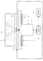
本実施形態に係る観察装置103は、図1に示されるように、例えば細胞などの試料Xを培養液とともに収容した培養容器2を搭載するベース3と、該ベース3に設けられた光源部5、撮像部6、送受信部21および制御部22とを備えている。
培養容器2は、例えば、細胞培養用のフラスコであって、光学的に透明な材質からなっている。For example, as shown in FIG. 1, the
The
ベース3は例えば筺体であり、筺体内部に光源部5、撮像部6、送受信21および制御部22を備えている。ベース3の上面の少なくとも一部は、光学的に透明な材質(例えばガラス)からなる搭載面3aを備え、当該搭載面3a上に培養容器2を搭載する。インキュベータ内部は多湿状態となるので、ベース3は防水構造となっているのが好ましい。
撮像部6は、ベース3内部の搭載面3aの下方に配置され、搭載面3aを上方から透過して来る光を集光する対物レンズ4と、試料Xを透過した光を撮影する撮影光学系とを備えている。
光源部5は、対物レンズ4の径方向外方に配置され、搭載面3aを透過して上方に照明光を射出する。The
The
The
光源部5は、図1および図2に示されるように、対物レンズ4の周囲に、周方向および径方向に間隔をあけて複数配置されたLED光源(光源)7と、各LED光源7に対応して配置され、各LED光源7において発生した照明光を略平行光にする複数のコリメートレンズ8と、該コリメートレンズ8によりコリメートされた照明光を拡散させる拡散板9とを備えている。
As shown in FIG. 1 and FIG. 2, the
光源部5は、特定のLED光源7を独立して点灯させることができるようになっている(図1および図2は、点灯しているLED光源7をハッチングによって示している。)。
すなわち、対物レンズの径方向に異なる位置のLED光源7のみを点灯させることで、図1に実線で示されるように、搭載面3aおよび容器2の底面2bを下から上に向かって透過した後、容器2の天板2a内面において反射して、斜め上方から試料X、容器2の底面2bおよび搭載面3aを透過して対物レンズ4に入射する照明光の角度を、破線で示されるように切り替えることができるようになっている。The
That is, by turning on only the
また、対物レンズ4の周方向に特定位置のLED光源7のみを点灯させることにより、試料Xに対して周方向の特定の方向からのみ照明することができるようになっている。また、図2に示されるように、対物レンズ4の周方向に2以上の方向、特に、対物レンズ4の光軸に対して軸対称の方向に配置されたLED光源7を点灯させることにより、照明ムラを低減した照明光を試料Xに対して照射することができるようになっている。
Further, by lighting only the
光源部5は、対物レンズの周囲に、周方向にのみ間隔をあけて複数配置されたLED光源(光源)7と、各LED光源7に対応して配置され、各LED光源7において発生した照明光を略平行光にする複数のコリメートレンズ8と、該コリメートレンズ8によりコリメートされた照明光を拡散させる拡散板9とを備えていてもよい。
周方向に90度間隔をあけて、LED光源(光源)7、コリメートレンズ8、拡散板9をそれぞれ4個備えていてもよい。The
At intervals of 90 degrees in the circumferential direction, four LED light sources (light sources) 7,
このように構成された本実施形態に係る観察装置103を用いた観察方法について、以下に説明する。
本実施形態に係る観察装置103を用いて細胞のように透明な試料Xの観察を行うには、図1に示されるように、試料Xを容器2内に収容し、底面2bに接着させた状態で、容器2を底面2bが下側になるようにステージ3の搭載面3a上に載置する。An observation method using the
In order to observe a transparent sample X like a cell using the
そして、この状態で、光源部5のいずれかのLED光源7を作動させて照明光を発生させる。LED光源7において発生した照明光は、該LED光源7に対応して配置されているコリメートレンズ8によってコリメートされ、拡散板9によって拡散された状態で、搭載面および容器2の底面2bを下から上に向かって透過し(射出ステップ)、容器2の天板2a内面において反射して試料Xに対して斜め上方から照射される(反射ステップ)。
Then, in this state, one of the
試料Xに照射された照明光のうち、試料Xを透過した照明光の透過光が容器2の底面2bおよび搭載面を上から下に向かって透過して、対物レンズ4に入射する(透過ステップ)。この際、照明光は試料Xの形状や屈折率によって屈折、散乱され、あるいは、試料Xの透過率によって減光されることで、試料Xの情報を載せた透過光となって対物レンズ4により集光され、図示しない撮像素子によって撮影される(撮影ステップ)。
Of the illumination light irradiated to the sample X, the transmitted light of the illumination light transmitted through the sample X is transmitted from the top to the bottom of the
このように、本実施形態に係る観察装置103によれば、試料Xの下方に光源部5および対物レンズ4を含む撮影光学系を配置しているので、試料Xの片側のみに光源部5および撮影光学系6を集約し、装置を薄型化することができるという利点がある。また、そのように薄型化した観察装置103においても、透過光を撮影することにより細胞等の被写体を標識せずに観察することができるという利点がある。
As described above, according to the
また、光源部5からの照明光は、対物レンズ4の径方向外方から射出され容器2の天板2a内面において反射することにより、試料Xに対して斜め上方から照射されて対物レンズ4により集光されるので、試料Xへの入射角度を適切に設定することにより、試料Xの像に明暗を形成することができ、細胞等の透明な被写体についても見やすい像を取得することができるという利点がある。
Further, the illumination light from the
また、本実施形態においては、光源部5が、対物レンズ4の周囲に径方向に配列され、独立して点灯可能な複数のLED光源7を備えているので、図1に破線で示されるように、点灯するLED光源7の径方向位置を異ならせることにより、試料Xに入射する照明光の照射角度を変化させることができる。これにより、対物レンズ4の取り込み角より小さい入射角の場合は、照明ムラの少ない明視野照明とし、また対物レンズ4の取り込み角より大きい入射角の場合は、微細構造が強調される暗視野照明とし、さらに対物レンズ4の取り込み角と同等の入射角の場合は、試料Xが立体的に見える偏斜照明とすることができる。
Further, in the present embodiment, since the
また、本実施形態においては、光源部5が、対物レンズ4の周囲に周方向に配列され、独立して点灯可能な複数のLED光源7を備えているので、点灯するLED光源7の周方向位置を異ならせることにより、試料Xに入射する照明光の照射方向を変化させることができる。これにより、形成される試料Xの像の陰影の方向を変化させ、見え方を変更することができる。
Further, in the present embodiment, since the
また、図2に示されるように、周方向に異なる位置の複数のLED光源7を同時に点灯させることにより、特に、軸対称に配置される複数のLED光源7を同時に点灯させることにより、照明ムラを低減してムラの少ない試料Xの画像を取得することができるという利点がある。
Further, as shown in FIG. 2, the illumination unevenness is caused by simultaneously turning on the plurality of
また、本実施形態においては、各LED光源7に対応して拡散板9が備えられているので、LED光源7から発せられた照明光が均一に拡散され,照明ムラの少ない均一な強度の照明光を試料Xに照射することができる。
Further, in the present embodiment, since the
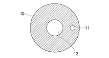
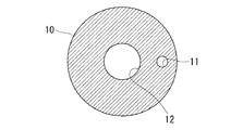
なお、本実施形態においては、複数のLED光源7をアレイ状に配列し、独立して点灯させることで、照明光の照射角度や照射方向等を切り替えることとしたが、これに代えて、図3ならびに図4Aから図4C、図5Aおよび図5Bに示されるように、光源部5が、対物レンズ4の周囲に配置される光源7と、該光源7の上方に配置され、光源7からの照明光を遮蔽する遮光部材10とを備えることにしてもよい。
In the present embodiment, the plurality of
すなわち、遮光部材10にはその周方向の一部あるいは径方向の一部に開口する開口部11と、容器2の天板2a内面において反射して試料Xを透過した光を透過させる透過孔12とが設けられており、遮光部材10を入れ替えることで、開口部11の位置を調節して、照明光の照射角度や照射方向を変更することができる。この場合には、光源部5としては、上記と同様にアレイ状に配列されたLED光源7、コリメートレンズ8および拡散板9を備えるものでもよいが、照明光の発光位置を切り替える機能は不要であり、開口部11より広い範囲から照明光を射出可能な光源であれば、任意の光源を備えるものを採用してもよい。
That is, the
図4Aから図4Cは円形の開口部11を有する例であり、径方向や開口部11の個数が異なる例を示している。図5Aは開口部11が扇形状の場合、図5Bは開口部11が円環状の場合をそれぞれ示している。開口部11の大きさ、位置および形状は任意のものを採用することができる。
FIGS. 4A to 4C show an example having
本実施形態においては、細胞培養フラスコのような天板2aを有する容器2内に試料Xを収容し、容器2の天板2a内面において照明光を反射させることとしたが、これに限定されるものではない。例えば、容器2として、シャーレ(蓋なし)のように天板2aを有しない容器13に試料Xを収容した場合には、図6に示されるように、シャーレの上部開口を閉塞する位置にミラーのような反射部材14を配置し、反射部材14によって底面13bを下から上に向かって透過した照明光を反射することにしてもよい。反射部材14は、直動によりあるいは揺動により試料Xの上方位置に挿脱可能に設けられていてもよい。
In the present embodiment, the sample X is accommodated in the
容器2として、シャーレ(蓋なし)のように天板2aを有しない容器13に試料Xを収容した場合には、図7に示されるように、容器13内に溶液(例えば、培養培地やリン酸緩衝液等)Lを入れて試料Xを溶液内に浸し、溶液上方の液面によって底面13bを下から上に向かって透過した照明光を反射することにしてもよい。天板2aを有する容器2に試料Xを収容した場合も、容器2内に溶液(例えば、培養培地やリン酸緩衝液等)Lを入れて試料Xを溶液内に浸してもよい。
When the sample X is housed in the
また、本実施形態においては、図8に示されるように、天板2aの上方に光を遮蔽する材質からなる遮光部材15を備えていてもよい。
このようにすることで、外部からの外光が遮光部材15によって遮蔽されるため、外光が天板2aから容器2内に入射することを抑制し、効率的に観察を行うことができる。In the present embodiment, as shown in FIG. 8, a
By doing this, external light from the outside is shielded by the
また、本実施形態においては、光源部5として、LED光源7、コリメートレンズ8および拡散板9をガラス板3aに沿うように略水平に配置したものを例示したが、これに代えて、図9に示されるように、LED光源7、コリメートレンズ8および拡散板9を光軸Sに向けて傾けて配置してもよい。
このようにすることで、LED光源7から発せられる照明光のロスを抑制し、効率的に照明光を試料Xに照射することができる。Further, in the present embodiment, as the
By doing this, the loss of the illumination light emitted from the LED
また、本実施形態においては、光源部5として、拡散板9を備えるものを例示したが、拡散板9を備えていなくてもよい。
Moreover, although the thing provided with the
送受信部21は、有線または無線によってインキュベータ外部に設置されたステーションサーバ104と情報の授受を行うようになっている。撮像部6により取得された画像を有線または無線によって外部のステーションサーバ104に送信したり、ステーションサーバ104からの情報を受信し制御部22に当該情報を送信したりする。
The transmission /
制御部22は、ステーションサーバ104からの情報に基づいて、光源部3、撮像部6および送受信部21を作動させるようになっている。
または、例えば、図示しないタイマーを備えており、定期的に光源部3、撮像部6および送受信部21を作動させるようになっていてもよい。The
Alternatively, for example, a timer (not shown) may be provided to periodically operate the
ステーションサーバ104はインキュベータ外に配置され、有線または無線でインキュベータ内の観察装置103と情報を授受する。また、ステーションサーバ104は、有線または無線でユーザ端末105と情報を授受する。
ステーションサーバ104は、観察装置から送信されたサンプルデータ(画像など)を受信し、当該サンプルデータをユーザ端末105に送信する。また、ユーザ端末105から送信された情報に基づいてインキュベータ内の観察装置103に情報を送信する。
ステーションサーバ104は、表示手段(モニタ)を備え、観察装置から送信されたサンプルデータを当該表示手段に表示してもよい。この場合ユーザ端末105がなくてもよい。
ステーションサーバ104は、図示しない入力手段(例えば、キーボード、マウス)を備え、当該入力手段により入力された情報をインキュベータ内の観察装置に送信してもよい。この場合ユーザ端末105がなくてもよい。
ステーションサーバ104は、例えば、PCである。The
The
The
The
The
ユーザ端末105は表示部と入力部を備え、無線でステーションサーバ104と情報を授受する。
ユーザ端末105は、ステーションサーバ104から送信されたサンプルデータを受信し、当該サンプルデータをユーザ端末105の表示部に表示する。また、ユーザ端末105の入力部に入力された情報をステーションサーバ104に送信する。
ユーザ端末105は、例えば、PC、スマートフォン、タブレットである。The
The
The
(第2実施形態)
本発明の第2の実施形態に係る培養観察システム200について、図面を参照して以下に説明する。
本実施形態に係る培養観察システム200は、図11に示されるように、インキュベータ101内に配置された培養容器2内のサンプル(例えば細胞)をモニタリングするための観察装置103と、インキュベータ101外に配置されインキュベータ101内の観察装置103と情報を授受するステーションサーバ104と、該ステーションサーバ104とインターネットを介して情報を授受するクラウドサーバ201と、該クラウドサーバ201とインターネットを介して情報を授受するユーザ端末105とを備えている。
ステーションサーバ104とユーザ端末105がクラウドサーバ201を介して情報の授受をする点で第1実施形態と異なっている。
観察装置103は、第1実施形態と同様である。Second Embodiment
A
As shown in FIG. 11, the
This embodiment differs from the first embodiment in that the
The
ステーションサーバ104はインキュベータ101外に配置され、有線または無線でインキュベータ101内の観察装置103と情報を授受する。また、ステーションサーバ104は、インターネット上のクラウドサーバ201を介してユーザ端末105と情報を授受する。
ステーションサーバ104は、観察装置103から送信された画像データを受信し、当該画像データをユーザ端末105に送信する。また、ユーザ端末105から送信された情報に基づいてインキュベータ101内の観察装置103に情報を送信する。
ステーションサーバ104からのクラウドサーバ201への情報の授受は、ユーザ端末105からの都度の指示に応じて行われてもよいし、予め決められた所定の間隔、および/または所定の画像データに対して自動で行われてもよい。
ステーションサーバ104は、例えば、PCである。The
The
The exchange of information from the
The
ユーザ端末105は表示部と入力部を備え、インターネット上のクラウドサーバ201およびインターネット上のクラウドサーバ201を介してステーションサーバ104と情報を授受する。
ユーザ端末105は、ステーションサーバ104またはクラウドサーバ201から送信されたサンプルデータ(画像など)を受信し、当該サンプルデータをユーザ端末105の表示部に表示する。また、ユーザ端末105の入力部に入力された情報をステーションサーバ104に送信する。
ユーザ端末105は、例えば、PC、スマートフォン、タブレットである。The
The
The
ステーションサーバ104からクラウドサーバ201へアップロードされるサンプルデータは画像だけでなく、画像解析データ(解析結果、解析条件など)、観察装置103のプロジェクトデータ(操作者名、性別、年齢、画像取得条件など)、観察装置103の操作情報ログデータ(装置一時停止、再開、タスク処理情報、累積稼働時間など)、作業情報ログデータ(培地交換、継代作業など)、培養情報データ(容器種類、細胞種類、培地名、血清名など)、培養環境データ(培地色、成分情報、温度、湿度など)などが含まれていてもよい。
これらのデータを画像データと紐つけて適切に表示することで、元来、作業者がインキュベータから細胞容器を取り出し、顕微鏡等を用いて細胞の様子を観察することで細胞状態を把握していたことに比べ、培養中の細胞状況をより多角的かつ定量的に把握することが可能となる。
また、クラウドサーバ201上でステーションサーバ104からアップロードされたサンプルデータを解析・分析・可視化を行ってもよい。こうすることで、観察装置103およびステーションサーバ104では実施することが出来ない解析・分析・可視化を観察装置103およびステーションサーバ104の構成、仕様を変更することなく実現することが可能となる。The sample data uploaded from the
By displaying these data in association with the image data and displaying them properly, the worker originally took out the cell container from the incubator and grasped the cell state by observing the state of the cell using a microscope etc. In comparison with the above, it becomes possible to grasp the cell condition in the culture more diversely and quantitatively.
Also, the sample data uploaded from the
上記各実施形態において、観察装置は、光源部および撮像部を移動する移動手段を有していてもよい。 In each of the above embodiments, the observation apparatus may have a moving unit that moves the light source unit and the imaging unit.
上記各実施形態においては、観察装置は、光源部5として、コリメートレンズ8および拡散板9を備えるものを例示したが、例えば図12に示すように、コリメートレンズ8および拡散板9を備えていなくてもよい。
In each of the above embodiments, the observation apparatus has exemplified the
上記各実施形態においては、観察装置がベース内に光源部を配置している態様を示したが、容器の上方に光源部を配置してもよいし、容器の側面に光源部を配置してもよい。 In the above embodiments, the light source unit is disposed in the base in the observation device. However, the light source unit may be disposed above the container, or the light source unit may be disposed on the side surface of the container. It is also good.
(参考実施形態)
本発明の一実施形態に係る観察装置100について図面を参照して以下に説明する。
本実施形態に係る観察装置100は、図13に示されるように、試料Xを収容した容器2を載置するステージ3と、該ステージ3の下方に配置され、ステージ3を上方から透過して来る光を集光する対物レンズ4を備え、試料Xを透過した光を撮影する撮影光学系6と、対物レンズ4の径方向外方に配置され、ステージ3を透過して上方に照明光を射出する光源部5とを備えている。(Reference embodiment)
An
As shown in FIG. 13, the
ステージ3には、対物レンズ4および光源部5の上方を覆うように、光学的に透明な材質、例えば、ガラス板3aが配置され、容器2はガラス板3aの上面に載置されるようになっている。
容器2は、例えば、天板2aを有する細胞培養フラスコであり、全体的に光学的に透明な樹脂により構成されている。An optically transparent material, for example, a
The
光源部5は、図13および図14に示されるように、対物レンズ4の周囲に、周方向および径方向に間隔をあけて複数配置されたLED光源(光源)7と、各LED光源7に対応して配置され、各LED光源7において発生した照明光を略平行光にする複数のコリメートレンズ8と、該コリメートレンズ8によりコリメートされた照明光を拡散させる拡散板9とを備えている。
As shown in FIG. 13 and FIG. 14, the
光源部5は、特定のLED光源7を独立して点灯させることができるようになっている(図13および図14は、点灯しているLED光源7をハッチングによって示している。)。
すなわち、対物レンズ4の径方向に異なる位置のLED光源7のみを点灯させることで、図13に実線で示されるように、ガラス板3aおよび容器2の底面2bを下から上に向かって透過した後、容器2の天板2a内面において反射して、斜め上方から試料X、容器2の底面2bおよびガラス板3aを透過して対物レンズ4に入射する照明光の角度を、破線で示されるように切り替えることができるようになっている。The
That is, by turning on only the
また、対物レンズ4の周方向に特定位置のLED光源7のみを点灯させることにより、試料Xに対して周方向の特定の方向からのみ照明することができるようになっている。また、図14に示されるように、対物レンズ4の周方向に2以上の方向、特に、対物レンズ4の光軸Sに対して軸対称の方向に配置されたLED光源7を点灯させることにより、照明ムラを低減した照明光を試料Xに対して照射することができるようになっている。
Further, by lighting only the
このように構成された本実施形態に係る観察装置1を用いた観察方法について、以下に説明する。
本実施形態に係る観察装置1を用いて細胞のように透明な試料Xの観察を行うには、図13に示されるように、試料Xを容器2内に収容し、底面2bに接着させた状態で、容器2を底面2bが下側になるようにステージ3のガラス板3a上に載置する。An observation method using the
In order to observe a transparent sample X such as a cell using the
そして、この状態で、光源部5のいずれかのLED光源7を作動させて照明光を発生させる。LED光源7において発生した照明光は、該LED光源7に対応して配置されているコリメートレンズ8によってコリメートされ、拡散板9によって拡散された状態で、ガラス板3aおよび容器2の底面2bを下から上に向かって透過し(射出ステップ)、容器2の天板2a内面において反射して試料Xに対して斜め上方から照射される(反射ステップ)。
Then, in this state, one of the
試料Xに照射された照明光のうち、試料Xを透過した照明光の透過光が容器2の底面2bおよびガラス板3aを上から下に向かって透過して、対物レンズ4に入射する(透過ステップ)。この際、照明光は試料Xの形状や屈折率によって屈折、散乱され、あるいは、試料Xの透過率によって減光されることで、試料Xの情報を載せた透過光となって対物レンズ4により集光され、図示しない撮像素子によって撮影される(撮影ステップ)。
Of the illumination light irradiated to the sample X, the transmitted light of the illumination light transmitted through the sample X is transmitted from the top to the bottom of the
このように、本実施形態に係る観察装置100によれば、試料Xの下方に光源部5および対物レンズ4を含む撮影光学系6を配置しているので、従来、試料を挟んだ両側に光源部と撮影光学系とを配置していた透過光の観察装置と比較すると、試料Xの片側のみに光源部5および撮影光学系6を集約し、装置を薄型化することができるという利点がある。また、そのように薄型化した観察装置100においても、透過光を撮影することにより細胞等の被写体を標識せずに観察することができるという利点がある。
As described above, according to the
また、光源部5からの照明光は、対物レンズ4の径方向外方から射出され容器2の天板2a内面において反射することにより、試料Xに対して斜め上方から照射されて対物レンズ4により集光されるので、試料Xへの入射角度を適切に設定することにより、試料Xの像に明暗を形成することができ、細胞等の透明な被写体についても見やすい像を取得することができるという利点がある。
Further, the illumination light from the
また、本実施形態においては、光源部5が、対物レンズ4の周囲に径方向に配列され、独立して点灯可能な複数のLED光源7を備えているので、図13に破線で示されるように、点灯するLED光源7の径方向位置を異ならせることにより、試料Xに入射する照明光の照射角度を変化させることができる。これにより、対物レンズ4の取り込み角より小さい入射角の場合は、照明ムラの少ない明視野照明とし、また対物レンズ4の取り込み角より大きい入射角の場合は、微細構造が強調される暗視野照明とし、さらに対物レンズ4の取り込み角と同等の入射角の場合は、試料Xが立体的に見える偏斜照明とすることができる。
Further, in the present embodiment, since the
また、本実施形態においては、光源部5が、対物レンズ4の周囲に周方向に配列され、独立して点灯可能な複数のLED光源7を備えているので、点灯するLED光源7の周方向位置を異ならせることにより、試料Xに入射する照明光の照射方向を変化させることができる。これにより、形成される試料Xの像の陰影の方向を変化させ、見え方を変更することができる。
Further, in the present embodiment, since the
また、図14に示されるように、周方向に異なる位置の複数のLED光源7を同時に点灯させることにより、特に、軸対称に配置される複数のLED光源7を同時に点灯させることにより、照明ムラを低減してムラの少ない試料Xの画像を取得することができるという利点がある。
In addition, as shown in FIG. 14, illumination unevenness is caused by simultaneously turning on the plurality of
また、本実施形態においては、各LED光源7に対応して拡散板9が備えられているので、LED光源7から発せられた照明光が均一に拡散され,照明ムラの少ない均一な強度の照明光を試料Xに照射することができる。
Further, in the present embodiment, since the
なお、本実施形態においては、複数のLED光源7をアレイ状に配列し、独立して点灯させることで、照明光の照射角度や照射方向等を切り替えることとしたが、これに代えて、図15ならびに図16Aから図16C、図17Aおよび図17Bに示されるように、光源部5が、対物レンズ4の周囲に配置される光源7と、該光源7の上方に配置され、光源7からの照明光を遮蔽する遮光部材10とを備えることにしてもよい。
In the present embodiment, the plurality of
すなわち、遮光部材10にはその周方向の一部あるいは径方向の一部に開口する開口部11と、容器2の天板2a内面において反射して試料Xを透過した光を透過させる透過孔12とが設けられており、遮光部材10を入れ替えることで、開口部11の位置を調節して、照明光の照射角度や照射方向を変更することができる。この場合には、光源部5としては、上記と同様にアレイ状に配列されたLED光源7、コリメートレンズ8および拡散板9を備えるものでもよいが、照明光の発光位置を切り替える機能は不要であり、開口部11より広い範囲から照明光を射出可能な光源であれば、任意の光源を備えるものを採用してもよい。
That is, the
図16Aから図16Cは円形の開口部11を有する例であり、径方向や開口部11の個数が異なる例を示している。図17Aは開口部11が扇形状の場合、図17Bは開口部11が円環状の場合をそれぞれ示している。開口部11の大きさ、位置および形状は任意のものを採用することができる。
16A to 16C show an example having
本実施形態においては、細胞培養フラスコのような天板2aを有する容器2内に試料Xを収容し、容器2の天板2a内面において照明光を反射させることとしたが、これに限定されるものではない。例えば、容器2として、シャーレ(蓋なし)のように天板2aを有しない容器13に試料Xを収容した場合には、図18に示されるように、シャーレの上部開口を閉塞する位置にミラーのような反射部材14を配置し、反射部材14によって底面13bを下から上に向かって透過した照明光を反射することにしてもよい。反射部材14は、直動によりあるいは揺動により試料Xの上方位置に挿脱可能に設けられていてもよい。
In the present embodiment, the sample X is accommodated in the
容器2として、シャーレ(蓋なし)のように天板2aを有しない容器13に試料Xを収容した場合には、図19に示されるように、容器13内に溶液(例えば、培養培地やリン酸緩衝液等)Lを入れて試料Xを溶液内に浸し、溶液上方の液面によって底面13bを下から上に向かって透過した照明光を反射することにしてもよい。天板2aを有する容器2に試料Xを収容した場合も、容器2内に溶液(例えば、培養培地やリン酸緩衝液等)Lを入れて試料Xを溶液内に浸してもよい。
When the sample X is housed in the
また、本実施形態においては、図20に示されるように、天板2aの上方に光を遮蔽する材質からなる遮光部材15を備えていてもよい。
このようにすることで、外部からの外光が遮光部材15によって遮蔽されるため、外光が天板2aから容器2内に入射することを抑制し、効率的に観察を行うことができる。Further, in the present embodiment, as shown in FIG. 20, a
By doing this, external light from the outside is shielded by the
また、本実施形態においては、光源部5として、LED光源7、コリメートレンズ8および拡散板9をガラス板3aに沿うように略水平に配置したものを例示したが、これに代えて、図21に示されるように、LED光源7、コリメートレンズ8および拡散板9を光軸Sに向けて傾けて配置してもよい。
このようにすることで、LED光源7から発せられる照明光のロスを抑制し、効率的に照明光を試料Xに照射することができる。Further, in the present embodiment, as the
By doing this, the loss of the illumination light emitted from the LED
また、本実施形態においては、光源部5として、コリメートレンズ8および拡散板9を備えるものを例示したが、コリメートレンズ8および拡散板9を備えていなくてもよい。
Moreover, in this embodiment, although what provided the
本実施形態によれば、以下の観察装置を提供できる。
(項目1)
試料の下方から上方に向けて照明光を射出する光源部と、
該光源部から射出された照明光が前記試料の上方で反射されて前記試料を透過した透過光を前記試料の下方において撮影する撮影光学系とを備える観察装置。
(項目2)
上記観察装置は、前記撮影光学系が、前記試料を透過した透過光を集光する対物レンズを備え、
前記光源部が、前記対物レンズの径方向外方から前記試料の上方に照明光を射出する観察装置であってもよい。
(項目3)
上記観察装置は、前記光源部が、前記対物レンズの径方向に異なる位置から独立して照明光を射出可能である観察装置であってもよい。
(項目4)
上記観察装置は、前記光源部が、前記対物レンズの周方向に異なる位置から同時に照明光を射出可能である観察装置であってもよい。
(項目5)
上記観察装置は、前記光源部が、前記対物レンズの周囲に配列され、独立して点灯可能な複数の光源を備える観察装置であってもよい。
(項目6)
上記観察装置は、前記光源部が、前記試料の下方に配置される光源と、該光源からの照明光のうち、特定の径方向位置の照明光のみを透過させる開口部を有する遮光部材とを備える観察装置であってもよい。
(項目7)
上記観察装置は、前記光源部が、照明光を拡散させる拡散板を備える観察装置であってもよい。
(項目8)
上記観察装置は、前記試料が、光学的に透明な材質からなる容器内に収容され、
前記照明光が前記試料の上方に配置されている前記容器の天板内面によって反射される観察装置であってもよい。
(項目9)
上記観察装置は、前記照明光が、前記試料の上方に配置された反射部材によって反射される観察装置であってもよい。
(項目10)
上記観察装置は、前記試料が、溶液内に浸されており、
前記照明光が、前記溶液の上方の液面によって反射される観察装置であってもよい。According to the present embodiment, the following observation apparatus can be provided.
(Item 1)
A light source unit that emits illumination light from the lower side to the upper side of the sample;
And a photographing optical system for photographing, under the sample, the transmitted light which is reflected by illumination light emitted from the light source section above the sample and transmitted through the sample.
(Item 2)
In the observation apparatus, the photographing optical system includes an objective lens that condenses transmitted light transmitted through the sample.
The light source unit may be an observation device that emits illumination light from the radially outer side of the objective lens to the upper side of the sample.
(Item 3)
The observation device may be an observation device in which the light source unit can independently emit illumination light from different positions in the radial direction of the objective lens.
(Item 4)
The observation device may be an observation device in which the light source unit can simultaneously emit illumination light from different positions in the circumferential direction of the objective lens.
(Item 5)
The observation apparatus may be an observation apparatus in which the light source unit includes a plurality of light sources which are arranged around the objective lens and can be independently lit.
(Item 6)
In the observation apparatus, the light source unit includes a light source disposed below the sample, and a light blocking member having an opening through which only illumination light at a specific radial position among illumination light from the light source is transmitted. It may be an observation device provided.
(Item 7)
The observation device may be an observation device in which the light source unit includes a diffusion plate for diffusing illumination light.
(Item 8)
In the observation apparatus, the sample is accommodated in a container made of an optically transparent material,
It may be an observation device in which the illumination light is reflected by the top plate inner surface of the container disposed above the sample.
(Item 9)
The observation device may be an observation device in which the illumination light is reflected by a reflecting member disposed above the sample.
(Item 10)
In the observation device, the sample is immersed in a solution;
It may be an observation device in which the illumination light is reflected by a liquid surface above the solution.
本実施形態によれば、以下の観察方法を提供する。
試料の下方から上方に向けて照明光を射出する射出ステップと、
該射出ステップにより射出された照明光を前記試料の上方において反射する反射ステップと、
該反射ステップにより反射された照明光を前記試料に透過させる透過ステップと、
該透過ステップにより前記試料を透過した透過光を前記試料の下方において撮影する撮影ステップとを含む観察方法。According to this embodiment, the following observation method is provided.
An emission step of emitting illumination light from the lower side to the upper side of the sample;
Reflecting the illumination light emitted by the emitting step above the sample;
Transmitting the illumination light reflected by the reflecting step to the sample;
And a photographing step of photographing the transmitted light transmitted through the sample by the transmitting step under the sample.
1 観察装置
2 容器
2a 天板
4 対物レンズ
5 光源部
6 撮影光学系
7 LED光源
9 拡散板
10 遮光部材
11 開口部
14 反射部材
21 送受信部
22 制御部
101 インキュベータ
103 観察装置
104 ステーションサーバ
105 ユーザ端末
201 クラウドサーバ
X 試料DESCRIPTION OF
Claims (20)
インキュベータ外に配置され、該観察装置と情報の授受をするステーションサーバと、
該ステーションサーバと情報の授受をする端末とを備えた培養観察システムであって、
前記観察装置は、
光学的に透明な材質からなる容器内に収容された試料の下方から上方に向けて照明光を射出する光源部と、
該光源部から射出された照明光が前記試料の上方で反射されて前記試料を透過した透過光を前記試料の下方において撮影する撮影部とを備え、
該撮影部が、前記試料を透過した透過光を集光する対物レンズを備え、
前記光源部が、前記対物レンズの径方向外方から前記試料の上方に照明光を射出する培養観察システム。 Disposed within the incubator, the observation apparatus for observing the sample in the container,
A station server disposed outside the incubator for exchanging information with the observation device;
A culture observation system comprising the station server and a terminal for exchanging information,
The observation device
A light source unit for emitting illumination light from the lower side to the upper side of the sample contained in a container made of an optically transparent material;
Illumination light emitted from the light source unit is reflected above the sample and transmitted through the sample, and an imaging unit configured to capture an image of the transmitted light below the sample ;
The imaging unit includes an objective lens configured to condense transmitted light transmitted through the sample;
Said light source unit, the objective lens culture observation system that emits illumination light above the sample from the radially outer side of the.
前記照明光が、前記溶液の上方の液面によって反射される請求項1から請求項9のいずれかに記載の培養観察システム。 The sample is immersed in the solution,
The culture observation system according to any one of claims 1 to 9 , wherein the illumination light is reflected by a liquid surface above the solution.
インキュベータ外に配置され、該観察装置と情報の授受をするステーションサーバとを備えた培養観察システムであって、A culture observation system comprising a station server disposed outside the incubator and exchanging information with the observation device,
前記ステーションサーバは入力手段を備え、The station server comprises input means,
前記観察装置は、The observation device
光学的に透明な材質からなる容器内に収容された試料の下方から上方に向けて照明光を射出する光源部と、A light source unit for emitting illumination light from the lower side to the upper side of the sample contained in a container made of an optically transparent material;
該光源部から射出された照明光が前記試料の上方で反射されて前記試料を透過した透過光を前記試料の下方において撮影する撮影部とを備え、Illumination light emitted from the light source unit is reflected above the sample and transmitted through the sample, and an imaging unit configured to capture an image of the transmitted light below the sample;
該撮影部が、前記試料を透過した透過光を集光する対物レンズを備え、The imaging unit includes an objective lens configured to condense transmitted light transmitted through the sample;
前記光源部が、前記対物レンズの径方向外方から前記試料の上方に照明光を射出する培養観察システム。The culture observation system in which the light source unit emits illumination light to the upper side of the sample from the radial outer side of the objective lens.
前記照明光が、前記溶液の上方の液面によって反射される請求項13から請求項17のいずれかに記載の培養観察システム。The culture observation system according to any one of claims 13 to 17, wherein the illumination light is reflected by a liquid level above the solution.
Applications Claiming Priority (3)
| Application Number | Priority Date | Filing Date | Title |
|---|---|---|---|
| JP2016192716 | 2016-09-30 | ||
| JP2016192716 | 2016-09-30 | ||
| PCT/JP2017/033979 WO2018061951A1 (en) | 2016-09-30 | 2017-09-20 | Culturing observing system |
Publications (2)
| Publication Number | Publication Date |
|---|---|
| JP6543002B2 true JP6543002B2 (en) | 2019-07-10 |
| JPWO2018061951A1 JPWO2018061951A1 (en) | 2019-07-18 |
Family
ID=61759636
Family Applications (1)
| Application Number | Title | Priority Date | Filing Date |
|---|---|---|---|
| JP2018542473A Active JP6543002B2 (en) | 2016-09-30 | 2017-09-20 | Culture observation system |
Country Status (5)
| Country | Link |
|---|---|
| US (1) | US20190218500A1 (en) |
| EP (1) | EP3521410A4 (en) |
| JP (1) | JP6543002B2 (en) |
| CN (1) | CN109790502A (en) |
| WO (1) | WO2018061951A1 (en) |
Families Citing this family (4)
| Publication number | Priority date | Publication date | Assignee | Title |
|---|---|---|---|---|
| WO2018062215A1 (en) | 2016-09-30 | 2018-04-05 | オリンパス株式会社 | Observation device |
| WO2018220670A1 (en) | 2017-05-29 | 2018-12-06 | オリンパス株式会社 | Observation device |
| JP7107523B2 (en) * | 2018-06-28 | 2022-07-27 | 株式会社エビデント | CULTURE MONITORING SYSTEM, STATE DISPLAY METHOD, AND PROGRAM |
| CN111007660A (en) * | 2019-12-25 | 2020-04-14 | 上海观纳智能科技有限公司 | Phase contrast microscope multi-mode ultrathin light source device and using method thereof |
Family Cites Families (10)
| Publication number | Priority date | Publication date | Assignee | Title |
|---|---|---|---|---|
| JP4652801B2 (en) * | 2004-12-22 | 2011-03-16 | オリンパス株式会社 | Transmission illumination apparatus, microscope equipped with the same, and transmission illumination method |
| KR100813915B1 (en) * | 2006-10-31 | 2008-03-18 | 전자부품연구원 | Cell culture detection apparatus |
| JP2009217222A (en) * | 2008-03-06 | 2009-09-24 | Takashi Goto | Observation base with reflection type transmissive illumination auxiliary device |
| JP2011008188A (en) * | 2009-06-29 | 2011-01-13 | Olympus Corp | Optical microscope |
| JP5552298B2 (en) * | 2009-11-11 | 2014-07-16 | 株式会社日立ハイテクノロジーズ | Bacterial colony fishing device and its pretreatment method |
| US9060684B2 (en) * | 2010-08-30 | 2015-06-23 | Panasonic Healthcare Holdings Co., Ltd. | Observation device, observation program, and observation system |
| JP2013152454A (en) * | 2011-12-27 | 2013-08-08 | Canon Inc | Image processing apparatus, image processing system, image processing method, and image processing program |
| JP6227564B2 (en) * | 2012-01-30 | 2017-11-08 | ライカ マイクロシステムス ツェーエムエス ゲーエムベーハー | Microscope and microscope system with wireless radio interface |
| JP6470008B2 (en) * | 2014-10-17 | 2019-02-13 | オリンパス株式会社 | Culture observation apparatus and culture observation system |
| CN205241704U (en) * | 2015-08-24 | 2016-05-18 | 杭州金源生物技术有限公司 | Intelligent long -range observation monitoring devices of cell culture case |
-
2017
- 2017-09-20 EP EP17855906.8A patent/EP3521410A4/en active Pending
- 2017-09-20 JP JP2018542473A patent/JP6543002B2/en active Active
- 2017-09-20 WO PCT/JP2017/033979 patent/WO2018061951A1/en unknown
- 2017-09-20 CN CN201780059546.6A patent/CN109790502A/en active Pending
-
2019
- 2019-03-21 US US16/360,205 patent/US20190218500A1/en not_active Abandoned
Also Published As
| Publication number | Publication date |
|---|---|
| EP3521410A4 (en) | 2020-04-15 |
| WO2018061951A1 (en) | 2018-04-05 |
| CN109790502A (en) | 2019-05-21 |
| US20190218500A1 (en) | 2019-07-18 |
| JPWO2018061951A1 (en) | 2019-07-18 |
| EP3521410A1 (en) | 2019-08-07 |
Similar Documents
| Publication | Publication Date | Title |
|---|---|---|
| JP6543002B2 (en) | Culture observation system | |
| US10281704B2 (en) | Observation apparatus and observation method to observe a sample with reflected light transmitted through the sample | |
| JP6514832B2 (en) | Observation device | |
| JP6005660B2 (en) | Observation system, control method and program for observation system | |
| KR101377694B1 (en) | Device for analyzing cell and monitoring cell culture and method of analyzing cell and monitoring cell culture using the same | |
| EP2917719B1 (en) | Receptacle and system for optically analyzing a sample without optical lenses | |
| WO2018062215A1 (en) | Observation device | |
| CN105319695B (en) | Transmitted light microscope and method for transmitted light microscopy | |
| JPWO2018061901A1 (en) | Observation device | |
| JP7379743B2 (en) | Systems and methods for managing multiple scanning devices in a high-throughput laboratory environment | |
| CA2978787C (en) | Method and apparatus for microscopy | |
| JP7196238B2 (en) | Cell observation system and cell observation method | |
| JP2017090842A (en) | Light shielding device, microscope, observation method, control method and program | |
| WO2017122401A1 (en) | Imaging device and imaging method | |
| JP6535494B2 (en) | Imaging device, imaging method and culture vessel | |
| CN113166701A (en) | Compact optical imaging system for cell culture monitoring | |
| CN112384606A (en) | Observation device |
Legal Events
| Date | Code | Title | Description |
|---|---|---|---|
| A521 | Request for written amendment filed |
Free format text: JAPANESE INTERMEDIATE CODE: A523 Effective date: 20190327 |
|
| A621 | Written request for application examination |
Free format text: JAPANESE INTERMEDIATE CODE: A621 Effective date: 20190327 |
|
| A871 | Explanation of circumstances concerning accelerated examination |
Free format text: JAPANESE INTERMEDIATE CODE: A871 Effective date: 20190327 |
|
| A975 | Report on accelerated examination |
Free format text: JAPANESE INTERMEDIATE CODE: A971005 Effective date: 20190417 |
|
| TRDD | Decision of grant or rejection written | ||
| A01 | Written decision to grant a patent or to grant a registration (utility model) |
Free format text: JAPANESE INTERMEDIATE CODE: A01 Effective date: 20190521 |
|
| A61 | First payment of annual fees (during grant procedure) |
Free format text: JAPANESE INTERMEDIATE CODE: A61 Effective date: 20190613 |
|
| R151 | Written notification of patent or utility model registration |
Ref document number: 6543002 Country of ref document: JP Free format text: JAPANESE INTERMEDIATE CODE: R151 |
|
| R250 | Receipt of annual fees |
Free format text: JAPANESE INTERMEDIATE CODE: R250 |
|
| S111 | Request for change of ownership or part of ownership |
Free format text: JAPANESE INTERMEDIATE CODE: R313111 |
|
| R371 | Transfer withdrawn |
Free format text: JAPANESE INTERMEDIATE CODE: R371 |
|
| S111 | Request for change of ownership or part of ownership |
Free format text: JAPANESE INTERMEDIATE CODE: R313111 |
|
| R350 | Written notification of registration of transfer |
Free format text: JAPANESE INTERMEDIATE CODE: R350 |
|
| R250 | Receipt of annual fees |
Free format text: JAPANESE INTERMEDIATE CODE: R250 |