WO2018058475A1 - 一种数据传输方法及设备 - Google Patents
一种数据传输方法及设备 Download PDFInfo
- Publication number
- WO2018058475A1 WO2018058475A1 PCT/CN2016/100952 CN2016100952W WO2018058475A1 WO 2018058475 A1 WO2018058475 A1 WO 2018058475A1 CN 2016100952 W CN2016100952 W CN 2016100952W WO 2018058475 A1 WO2018058475 A1 WO 2018058475A1
- Authority
- WO
- WIPO (PCT)
- Prior art keywords
- time slot
- special subframe
- downlink data
- time interval
- uplink
- Prior art date
Links
Images


Classifications
-
- H—ELECTRICITY
- H04—ELECTRIC COMMUNICATION TECHNIQUE
- H04L—TRANSMISSION OF DIGITAL INFORMATION, e.g. TELEGRAPHIC COMMUNICATION
- H04L5/00—Arrangements affording multiple use of the transmission path
- H04L5/003—Arrangements for allocating sub-channels of the transmission path
- H04L5/0044—Arrangements for allocating sub-channels of the transmission path allocation of payload
-
- H—ELECTRICITY
- H04—ELECTRIC COMMUNICATION TECHNIQUE
- H04W—WIRELESS COMMUNICATION NETWORKS
- H04W24/00—Supervisory, monitoring or testing arrangements
- H04W24/10—Scheduling measurement reports ; Arrangements for measurement reports
-
- H—ELECTRICITY
- H04—ELECTRIC COMMUNICATION TECHNIQUE
- H04L—TRANSMISSION OF DIGITAL INFORMATION, e.g. TELEGRAPHIC COMMUNICATION
- H04L1/00—Arrangements for detecting or preventing errors in the information received
- H04L1/12—Arrangements for detecting or preventing errors in the information received by using return channel
- H04L1/16—Arrangements for detecting or preventing errors in the information received by using return channel in which the return channel carries supervisory signals, e.g. repetition request signals
- H04L1/1607—Details of the supervisory signal
-
- H—ELECTRICITY
- H04—ELECTRIC COMMUNICATION TECHNIQUE
- H04L—TRANSMISSION OF DIGITAL INFORMATION, e.g. TELEGRAPHIC COMMUNICATION
- H04L5/00—Arrangements affording multiple use of the transmission path
- H04L5/003—Arrangements for allocating sub-channels of the transmission path
- H04L5/0058—Allocation criteria
-
- H—ELECTRICITY
- H04—ELECTRIC COMMUNICATION TECHNIQUE
- H04L—TRANSMISSION OF DIGITAL INFORMATION, e.g. TELEGRAPHIC COMMUNICATION
- H04L5/00—Arrangements affording multiple use of the transmission path
- H04L5/14—Two-way operation using the same type of signal, i.e. duplex
- H04L5/1469—Two-way operation using the same type of signal, i.e. duplex using time-sharing
-
- H—ELECTRICITY
- H04—ELECTRIC COMMUNICATION TECHNIQUE
- H04W—WIRELESS COMMUNICATION NETWORKS
- H04W72/00—Local resource management
- H04W72/04—Wireless resource allocation
- H04W72/044—Wireless resource allocation based on the type of the allocated resource
- H04W72/0446—Resources in time domain, e.g. slots or frames
-
- H—ELECTRICITY
- H04—ELECTRIC COMMUNICATION TECHNIQUE
- H04W—WIRELESS COMMUNICATION NETWORKS
- H04W72/00—Local resource management
- H04W72/20—Control channels or signalling for resource management
- H04W72/23—Control channels or signalling for resource management in the downlink direction of a wireless link, i.e. towards a terminal
-
- H—ELECTRICITY
- H04—ELECTRIC COMMUNICATION TECHNIQUE
- H04L—TRANSMISSION OF DIGITAL INFORMATION, e.g. TELEGRAPHIC COMMUNICATION
- H04L5/00—Arrangements affording multiple use of the transmission path
- H04L5/0001—Arrangements for dividing the transmission path
- H04L5/0003—Two-dimensional division
- H04L5/0005—Time-frequency
- H04L5/0007—Time-frequency the frequencies being orthogonal, e.g. OFDM(A), DMT
-
- H—ELECTRICITY
- H04—ELECTRIC COMMUNICATION TECHNIQUE
- H04L—TRANSMISSION OF DIGITAL INFORMATION, e.g. TELEGRAPHIC COMMUNICATION
- H04L5/00—Arrangements affording multiple use of the transmission path
- H04L5/0091—Signaling for the administration of the divided path
Definitions
- the embodiments of the present invention relate to the field of communications, and in particular, to a data transmission method and device.
- the Long Term Evolution (LTE) system is divided into a frequency division duplex system and a Time Division Duplex (TDD) system.
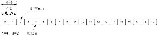
- the frame structure defined by the TDD system is as shown in FIG. 1.
- a 10 millisecond (ms) radio frame is composed of 10 1 ms subframes, including at least one downlink subframe, at least one uplink subframe, and at least one special.
- Sub-frames, downlink sub-frames can be used for downlink data transmission
- uplink sub-frames can be used for uplink data transmission.
- Special subframes include Downlink Pilot Time Slot (DwPTS) and Guard Period (Guard Period, GP) and Uplink Pilot TimeSlot (UpPTS).
- DwPTS Downlink Pilot Time Slot
- Guard Period Guard Period
- UpPTS Uplink Pilot TimeSlot
- the TDD system designs different configurations for special subframes, such as a conventional Cyclic Prefix (CP) in a TDD system (a subframe contains 14 symbols when the TDD system uses a conventional CP), and a special subframe
- CP Cyclic Prefix
- Table 1 shows the number of symbols occupied by DwPTS and UpPTS in different configurations.
- the Latency Reduction technology is introduced in the TDD system, which shortens the transmission time interval (TTI) of a conventional one subframe to half a subframe.
- TTI transmission time interval
- sTTI Short transmission time interval
- the prior art provides a scheme for transmitting downlink data by using DwPTS included in a special subframe for configurations other than #0, #5, and #9 in Table 1.
- the scheme divides the DwPTS included in the special subframe into two parts, and the first part includes 7 symbols, that is, the duration of the first part is 1 time slot (1 time slot is equal to 0.5 ms)
- the second part includes the remaining Z symbols (Z is an integer greater than or equal to 2 and less than or equal to 5), and only the first part included in the DwPTS transmits downlink data, and the second part is discarded unused for downlink data. transmission.
- Z is an integer greater than or equal to 2 and less than or equal to 5
- the embodiment of the invention provides a frame structure and a data transmission method and device thereof, which solves the problem of waste of transmission resources caused by transmission of downlink data only by using some symbols included in the DwPTS.
- the embodiment of the present invention adopts the following technical solutions:
- a first aspect of the embodiments of the present invention provides a data transmission method, which is applied to a TDD system, and includes:
- the network device sends the second downlink data in the second time slot of the first time slot or the first time slot of the second special subframe in the first special subframe, where the first special subframe is a downlink A special subframe with a pilot slot duration greater than 0.5 milliseconds, and a second special subframe is a special subframe with a downlink pilot slot duration less than 0.5 milliseconds, and the second time interval includes N symbols, and N is greater than or equal to 2. And an integer less than or equal to 6.
- the second time interval when the TDD system adopts a regular CP, the second time interval includes N symbols, N is an integer greater than or equal to 2, and less than or equal to 6; when the TDD system adopts an extended CP, the second time interval includes M symbols , M is an integer greater than or equal to 2 and less than or equal to 5.
- the network device sends the first downlink data at the first time interval, and the second downlink data is sent at the second time interval, where the second time interval is located in the first special subframe.
- the second time slot or the first time slot of the second special subframe enables efficient use of all symbols in the DwPTS included in the special subframe
- the number is transmitted for downlink data, which avoids waste of transmission resources.
- the data transmission method provided by the embodiment of the present invention may further include: sending, by the network device, the first time interval of the first time slot located in the first special subframe The first downlink data.
- the first time interval when the TDD system adopts a conventional CP, the first time interval includes 7 symbols; when the TDD system adopts an extended CP, the first time interval includes 6 symbols.
- the data transmission method provided by the embodiment of the present invention may further include: the network device sending includes useful The second downlink control information (Downlink Control Information, DCI) indicating the control information of the second downlink data transmission, where the second DCI is located in the first time slot in the first special subframe, or the second DCI is located in the second A time slot preceding the special subframe and adjacent to the second special subframe.
- DCI Downlink Control Information
- the data transmission method provided by the embodiment of the present invention may further include: the network device sends the control information that is used to indicate the first downlink data transmission.
- the first DCI, the first DCI is located in the first time slot in the first special subframe.
- a second DCI that includes control information for indicating the second downlink data transmission, and a second downlink data transmission, Scheduling information.
- the embodiment of the present invention provides The data transmission method may further include: the network device receiving, in an uplink time slot n, reception state information of the second downlink data, where at least ki time slots are separated from a start position of the uplink time slot n and a start position of the second time interval
- k is an integer greater than or equal to 1, and less than or equal to 8
- i is a non-negative integer less than k.
- the sending The data transmission method provided by the embodiment may further include: the network device receiving the receiving state information of the first downlink data in the uplink time slot m, between the starting position of the uplink time slot m and the starting position of the first time interval At least k time slots apart, where k is an integer greater than or equal to 1, and less than or equal to 8.
- a second aspect of the embodiments of the present invention provides a data transmission method, which is applied to a TDD system, and includes:
- the terminal device receives the second downlink data in a second time slot located in the first special subframe or a second time interval in the first special time slot of the second special subframe, where the first special subframe is a downlink A special subframe with a pilot slot duration greater than 0.5 milliseconds, and a second special subframe is a special subframe with a downlink pilot slot duration less than 0.5 milliseconds, and the second time interval includes N symbols, and N is greater than or equal to 2. And an integer less than or equal to 6.
- the terminal device receives the first downlink data at the first time interval, and receives the second downlink data at the second time interval, where the second time interval is located in the first special subframe.
- the second time slot or the first time slot of the second special subframe enables efficient use of all symbols in the DwPTS included in the special subframe for downlink data transmission, thereby avoiding waste of transmission resources.
- the data transmission method provided by the embodiment of the present invention may further include: receiving, by the terminal device, the first time interval of the first time slot located in the first special subframe The first downlink data.
- the data transmission method provided by the embodiment of the present invention may further include: receiving, by the terminal device, useful And a second DCI indicating control information of the second downlink data transmission, where the second DCI is located in a first time slot in the first special subframe, or the second DCI is located before the second special subframe, and is in a second A time slot adjacent to a special subframe.
- the data transmission method provided by the embodiment of the present invention may further include: receiving, by the terminal device, control information, where the first downlink data transmission is included First DCI, the first A DCI is located in the first time slot in the first special subframe.
- the second DCI includes control information for indicating the second downlink data transmission, and further includes, for indicating the first downlink data transmission. Scheduling information.
- the transmission method may further include: the terminal device transmitting the receiving state information of the second downlink data in the uplink time slot n, where the starting position of the uplink time slot n and the starting position of the second time interval are at least KI time slots, Where k is an integer greater than or equal to 1, and less than or equal to 8, and i is a non-negative integer less than k.
- the data transmission method provided by the embodiment of the present invention may further include The terminal device sends the reception status information of the first downlink data in the uplink time slot m, and the start position of the uplink time slot m and the start position of the first time interval are at least k time slots, where k is An integer greater than or equal to 1, and less than or equal to 8.
- the embodiment of the present invention provides The data transmission method may further include: determining, by the terminal device, whether the number of symbols included in the second time interval is not less than a preset threshold, and determining that the number of symbols included in the second time interval is less than a preset threshold, the terminal device does not receive the weight.
- NACK non-acknowledgment
- a third aspect of the embodiments of the present invention provides an uplink control channel transmission method.
- TDD systems including:
- the network device sends the third downlink data on the first time slot, and receives, on the second time slot, an uplink physical control channel for carrying the reception status information of the third downlink data, where the uplink physical control channel is located in the special subframe.
- UpPTS contains 6 symbols.
- the uplink control channel transmission method provided by the embodiment of the present invention uses the UpPTS to carry the feedback work of the partial reception status information. Moreover, by using the feedback of the status information received by the UpPTS bearer part, the load of other uplink time slots is effectively reduced.
- the second time slot is a time slot in which the UpPTS is located
- the start position of the first time slot and the start position of the time slot in which the UpPTS is located are at least k time slots.
- k is an integer greater than or equal to 1, and less than or equal to 8.
- a fourth aspect of the embodiments of the present invention provides an uplink control channel transmission method, which is applied to a TDD system, and includes:
- the terminal device receives the third downlink data on the first time slot, and sends an uplink physical control channel for carrying the reception state information of the third downlink data, where the uplink physical control channel is located in the special subframe.
- UpPTS contains 6 symbols.
- the uplink control channel transmission method provided by the embodiment of the present invention uses the UpPTS to carry the feedback work of the partial reception status information. Moreover, by using the feedback of the status information received by the UpPTS bearer part, the load of other uplink time slots is effectively reduced.
- the second time slot is a time slot in which the UpPTS is located
- the start position of the first time slot and the start position of the time slot in which the UpPTS is located are at least k time slots.
- k is an integer greater than or equal to 1, and less than or equal to 8.
- a fifth aspect of the embodiments of the present invention provides a network device, which is applied to a TDD system, where the network device may include:
- a sending unit configured to send the second downlink data on the second time interval, where the second time interval is located in the second time slot or the second special subframe in the first special subframe
- the first special time slot is a special subframe in which the downlink pilot time slot duration is greater than 0.5 milliseconds
- the second special subframe is a special subframe in which the downlink pilot time slot duration is less than 0.5 milliseconds.
- the two time intervals include N symbols, and N is an integer greater than or equal to 2 and less than or equal to 6.
- the sending unit is further configured to send the first downlink data at a first time interval of the first time slot located in the first special subframe.
- the sending unit is further configured to send a second DCI that includes control information for indicating the second downlink data transmission, where the second DCI is located.
- the sending unit is further configured to send a first DCI that includes control information for indicating the first downlink data transmission, the first DCI Located in the first time slot in the first special subframe.
- the second DCI sent by the sending unit further includes scheduling information for indicating the first downlink data transmission.
- the network device provided by the embodiment of the present invention may further include: a receiving unit. a receiving unit, configured to receive, in the uplink time slot n, the receiving state information of the second downlink data, where the starting position of the uplink time slot n and the starting position of the second time interval are at least KI time slots, where k Is an integer greater than or equal to 1, and less than or equal to 8, i is a non-negative integer less than k.
- the network device provided by the embodiment of the present invention may further include: a receiving unit. a receiving unit, configured to receive, in the uplink time slot m, the receiving state information of the first downlink data, where the starting position of the uplink time slot m and the starting position of the first time interval are at least k apart A time slot, where k is an integer greater than or equal to 1, and less than or equal to 8.
- a sixth aspect of the embodiments of the present invention provides a terminal device, which is applied to a TDD system, where the terminal device includes:
- a receiving unit configured to receive second downlink data in a second time interval, where the second time interval is located in a second time slot in the first special subframe or a first time slot in the second special subframe,
- the second time interval includes N symbols, N is an integer greater than or equal to 2, and is less than or equal to 6.
- the first special subframe is a special subframe in which the downlink pilot time slot duration is greater than 0.5 milliseconds
- the frame is a special subframe in which the downlink pilot time slot duration is less than 0.5 milliseconds.
- the receiving unit is further configured to receive the first downlink data at the first time interval, where the first time interval is located in the first one of the first special subframes Gap.
- the receiving unit is further configured to receive the second DCI, where the second DCI includes control information for indicating the second downlink data transmission, and The second DCI is located in a first time slot in the first special subframe, or a time slot in which the second DCI is located before the second special subframe and is adjacent to the second special subframe.
- the receiving unit is further configured to receive the first DCI, where the first DCI includes control information for indicating the first downlink data transmission, and The first DCI is located in the first time slot in the first special subframe.
- the second DCI received by the receiving unit further includes scheduling information for indicating the first downlink data transmission.
- the terminal device provided by the embodiment of the present invention may further include: a sending unit, where the sending unit is configured to send the second downlink in the uplink time slot n
- the receiving state information of the data, the starting position of the uplink time slot n and the starting position of the second time interval are at least KI time slots, where k is an integer greater than or equal to 1, and less than or equal to 8, i is small A non-negative integer at k.
- the terminal device provided by the embodiment of the present invention may further include: a sending unit, and the sending unit is further configured to send the first time in the uplink time slot m.
- the receiving state information of the downlink data, the starting position of the uplink time slot m and the starting position of the first time interval are at least k time slots, wherein k is greater than or equal to 1, and less than or equal to 8. Integer.
- the terminal device when the terminal device needs to receive the retransmission data on the second time interval, the terminal device may further include: a determining unit; And determining, by the receiving unit, whether the number of symbols included in the second time interval is not less than a preset threshold, and the second time interval is The receiving unit is configured to receive the retransmission data, and the sending unit is further configured to: if the determining unit determines that the number of symbols included in the second time interval is less than a preset threshold, the terminal device does not receive the retransmitted data, and sends the retransmitted data in the uplink time slot s.
- the receiving status information is a non-acknowledgment NACK, at least ki time slots are separated between the starting position of the uplink time slot s and the starting position of the second time interval, and k is greater than or equal to 1, and less than or equal to An integer of 8, i is a non-negative integer less than k.
- a seventh aspect of the embodiments of the present invention provides a network device, which is applied to a TDD system, where the network device includes:
- a sending unit configured to send third downlink data on the first time slot
- a receiving unit configured to receive an uplink physical control channel on the second time slot, where the uplink physical control channel is used to receive the receiving state information of the third downlink data
- the uplink physical control channel is located in the UpPTS included in the special subframe, and the UpPTS contains 6 symbols.
- the second time slot is a time slot in which the UpPTS is located
- the start position of the first time slot and the start position of the time slot in which the UpPTS is located are at least k time slots.
- k is an integer greater than or equal to 1, and less than or equal to 8.
- An eighth aspect of the embodiments of the present invention provides a terminal device, which is applied to a TDD system, where the terminal device includes:
- a receiving unit configured to receive third downlink data on a first time slot; a sending unit,
- the uplink physical control channel is used to carry the receiving state information of the third downlink data, the uplink physical control channel is located in the UpPTS included in the special subframe, and the UpPTS includes 6 symbols.
- the second time slot is a time slot in which the UpPTS is located
- the start position of the first time slot and the start position of the time slot in which the UpPTS is located are at least k time slots.
- k is an integer greater than or equal to 1, and less than or equal to 8.
- a ninth aspect of the embodiments of the present invention provides a network device, which is applied to a TDD system, where the network device may include: a processor, a memory, and a transceiver;
- the memory is configured to store computer execution instructions, and when the network device is in operation, the processor executes the memory stored computer to execute the instructions to cause the terminal device to perform the data transmission as described in any of the first aspect or the possible implementation of the first aspect.
- a tenth aspect of the embodiments of the present invention provides a terminal device, which is applied to a TDD system, where the terminal device may include: a processor, a memory, and a transceiver;
- the memory is configured to store a computer execution instruction, and when the terminal device is in operation, the processor executes the memory stored computer to execute the instruction to cause the terminal device to perform the data transmission as described in any of the second aspect or the possible implementation manner of the second aspect The method, or the uplink control channel transmission method of any of the possible implementations of the fourth aspect or the fourth aspect.
- An eleventh aspect of the present invention provides a frame structure, which is applied to a TDD system, where the TDD system uses sTTI for data transmission, and the frame structure may include:
- At least one uplink subframe, at least one downlink subframe, and at least one special subframe the special subframe includes DwPTS, GP, and UpPTS, and the duration of the uplink subframe, the downlink subframe, and the special subframe is 1 millisecond.
- the special subframe When the duration of the DwPTS is greater than 0.5 milliseconds, the special subframe is a first special subframe, and the second time interval is located in a second time slot of the first special subframe.
- the duration of the DwPTS is less than 0.5 milliseconds, the The special subframe is a second special subframe, and the second time interval is located in a first time slot of the second special subframe; the second time interval is used for sending Second downlink data; the second time interval includes N symbols, and N is an integer greater than or equal to 2 and less than or equal to 6.
- the second time interval when the TDD system adopts a regular CP, the second time interval includes N symbols, N is an integer greater than or equal to 2, and less than or equal to 5; when the TDD system adopts an extended CP, the second time interval includes M The symbol, M is an integer greater than or equal to 2 and less than or equal to 5.
- the frame structure provided by the embodiment of the present invention may send the second downlink data in the second time interval, where the second time interval is located in the second time slot of the first special subframe or the first one of the second special subframes.
- the time slots enable all the symbols in the DwPTS included in the special subframe to be used for downlink data transmission, thereby avoiding waste of transmission resources.
- the special subframe is the first special subframe
- the first time interval is located in the first time slot in the first special subframe, and the first time interval is used.
- the first downlink data is sent.
- the first time interval when the TDD system adopts a conventional CP, the first time interval includes 7 symbols; when the TDD system adopts an extended CP, the first time interval includes 6 symbols.
- the first time interval is further configured to send the first downlink control information DCI and the second DCI, where the first DCI includes scheduling information for scheduling the first downlink data, and the second DCI includes scheduling information for scheduling the second downlink data.
- the time slot adjacent to the second special subframe is used to send the second DCI, and the second DCI includes control information for indicating the second downlink data transmission.
- the first time slot located in the first special subframe is used to send the first DCI, where the first DCI includes A control information for downlink data transmission.
- the second DCI further includes scheduling information for indicating the first downlink data transmission.
- the first time interval is located in the time slot qk or before the time slot qk. If the time slot q is used to feed back the reception status information of the second downlink data transmitted on the second time interval, the second time interval is located in the time slot q-k+i or before the time slot q-k+i, k Is an integer greater than or equal to 1, and less than or equal to 8, i is a non-negative integer less than k.
- FIG. 1 is a schematic diagram of a frame structure provided by the prior art
- FIG. 2 is a schematic structural diagram of a special subframe provided by the prior art
- FIG. 3 is a schematic structural diagram of a frame according to an embodiment of the present disclosure.
- FIG. 4 is a schematic structural diagram of another frame according to an embodiment of the present disclosure.
- FIG. 5 is a schematic structural diagram of another frame according to an embodiment of the present disclosure.
- FIG. 6 is a schematic structural diagram of another frame according to an embodiment of the present disclosure.
- FIG. 7 is a schematic structural diagram of another frame according to an embodiment of the present disclosure.
- FIG. 8 is a schematic structural diagram of another frame according to an embodiment of the present disclosure.
- FIG. 9 is a schematic structural diagram of another frame according to an embodiment of the present disclosure.
- FIG. 10 is a schematic structural diagram of another frame according to an embodiment of the present disclosure.
- FIG. 11 is a schematic structural diagram of another frame according to an embodiment of the present disclosure.
- FIG. 12 is a schematic structural diagram of another frame according to an embodiment of the present disclosure.
- FIG. 13 is a simplified schematic diagram of a wireless communication system to which an embodiment of the present invention is applied according to an embodiment of the present invention
- FIG. 14 is a schematic structural diagram of a network device according to an embodiment of the present disclosure.
- FIG. 15 is a schematic structural diagram of a terminal device according to an embodiment of the present disclosure.
- FIG. 16 is a flowchart of a data transmission method according to an embodiment of the present invention.
- FIG. 17 is a schematic structural diagram of another frame according to an embodiment of the present disclosure.
- FIG. 18 is a schematic structural diagram of another frame according to an embodiment of the present disclosure.
- FIG. 19 is a schematic structural diagram of another frame according to an embodiment of the present disclosure.
- FIG. 20 is a schematic structural diagram of another frame according to an embodiment of the present disclosure.
- FIG. 20 is a schematic structural diagram of another frame according to an embodiment of the present disclosure.
- FIG. 21 is a schematic diagram of a subframe configuration according to an embodiment of the present disclosure.
- FIG. 22 is a schematic diagram of feedback of receiving state information of downlink data according to an embodiment of the present disclosure.
- FIG. 23 is a schematic structural diagram of a special subframe according to an embodiment of the present invention.
- FIG. 23 is a flowchart of a method for transmitting an uplink control channel according to an embodiment of the present invention.
- FIG. 23B is a schematic structural diagram of an uplink physical control channel according to an embodiment of the present disclosure.
- FIG. 24 is a schematic structural diagram of another network device according to an embodiment of the present disclosure.
- FIG. 25 is a schematic structural diagram of another network device according to an embodiment of the present disclosure.
- FIG. 26 is a schematic structural diagram of another terminal device according to an embodiment of the present disclosure.
- FIG. 27 is a schematic structural diagram of another terminal device according to an embodiment of the present invention.
- system and “network” are often used interchangeably herein.
- the term “and/or” in this context is merely an association describing the associated object, indicating that there may be three relationships, for example, A and / or B, which may indicate that A exists separately, and both A and B exist, respectively. B these three situations.
- the character "/" in this article generally indicates that the contextual object is an "or" relationship.
- the invention provides a data transmission method, which The specific solution is: the network device sends the second downlink data at the second time interval, where the second time interval is located in the second time slot of the first special subframe or the first time slot of the second special subframe,
- the first special subframe is a special subframe in which the downlink pilot time slot duration is greater than 0.5 milliseconds
- the second special subframe is a special subframe in which the downlink pilot time slot duration is less than 0.5 milliseconds
- the second time interval includes N symbols.
- N is an integer greater than or equal to 2 and less than or equal to 6.
- the symbol performs downlink data transmission, avoiding waste of transmission resources.
- each radio frame is composed of 10 1 ms subframes, and the number of the 10 subframes may be 0 to 9, specifically: subframe 0 , subframe 1, subframe 2, subframe 3, subframe 4, subframe 5, subframe 6, subframe 7, subframe 8, subframe 9.
- the subframe n-a refers to the a-th subframe located before the subframe n, that is, the subframe n-a refers to the a-th subframe from the subframe n.
- the subframe n-a is the subframe 2 in the radio frame in which the subframe 4 is located.
- the subframe n-a is the subframe 8 in the previous radio frame of the radio frame in which the subframe 0 is located.
- the subframe n+a refers to the a-th subframe located after the subframe n, that is, the subframe n+a refers to the a-th subframe from the subframe n.
- the subframe n+a is the subframe 7 in the radio frame in which the subframe 4 is located.
- the subframe n+a is the subframe 0 in the next radio frame of the radio frame in which the subframe 8 is located.
- each subframe includes two slots with a duration of 0.5 ms, that is, each radio frame includes 20 slots, and the 20 The number of slots can be 0 to 19, specifically: slot 0, slot 1, slot 2, slot 3, slot 4, slot 5, slot 6, slot 7, slot 8.
- the time slot n-a refers to the a-th time slot before the time slot n, that is, the time slot n-a refers to the first time slot starting from the time slot n.
- the slot n-a is slot 2 in the radio frame in which slot 4 is located.
- the slot n-a is the slot 18 in the last radio frame of the radio frame in which slot 0 is located.
- the slot n+a refers to the a-th slot after the slot n, that is, the slot n+a refers to the a-th slot from the slot n to the next.
- slot n+a is slot 7 in the radio frame in which slot 4 is located.
- slot n+a is slot 0 in the next radio frame of the radio frame in which the slot 18 is located.
- the uplink symbol is called a single carrier-frequency division multiple access (SC-FDMA) symbol, and the downlink symbol is called an orthogonal frequency division multiplexing (OFDM) symbol.
- SC-FDMA single carrier-frequency division multiple access
- OFDM orthogonal frequency division multiplexing
- the uplink symbols may also be referred to as other types of symbols, such as OFDM symbols.
- the embodiments of the present invention do not specifically limit the uplink multiple access mode and the downlink multiple access mode.
- the number of symbols included in each slot is related to the length of the CP employed by the TDD system. If the CP is a regular CP, each slot includes 7 symbols, and each subframe consists of 14 symbols. For example, the number of each sub-frame is #0, #1, #2, #3, #4, #5, #6, #7, #8, #9, #10, #11, #12, #13 Symbol composition. If the CP is an extended CP, each slot includes 6 symbols, and each subframe consists of 12 symbols. For example, each sub-frame consists of symbols with numbers #0, #1, #2, #3, #4, #5, #6, #7, #8, #9, #10, #11.
- Hybrid Automatic Repeat Request (Hybrid Automatic Repeat Request, HARQ) Timing:
- the HARQ timing refers to the transmission time sequence between the downlink data transmission and the hybrid automatic repeat request acknowledgement (HARQ acknowledgement) (HARQ-ACK) feedback of the terminal device.
- HARQ acknowledgement hybrid automatic repeat request acknowledgement
- the frame structure of the TDD system includes: at least one uplink subframe, at least one downlink subframe, and at least one special subframe, where the special subframe includes DwPTS, GP, and UpPTS, durations of uplink subframes, downlink subframes, and special subframes. Both are 1 millisecond.
- the special subframe including the DwPTS may be referred to as a first special subframe.
- the special subframe including the DwPTS may be referred to as a second subframe.
- Special subframe The first time interval involved in the embodiment of the present invention is located in the first time slot in the first special subframe, the second time interval is located in the second time slot in the first special subframe, or is located in the second special time.
- the first time slot in the subframe that is, when the duration of the DwPTS included in the special subframe is greater than 0.5 milliseconds, the special subframe includes a first time interval and a second time interval, when the special subframe When the duration of the included DwPTS is less than 0.5 milliseconds, the special subframe includes a second time interval, excluding the first time interval.
- the embodiment of the invention adopts the frame structure for data transmission.
- the first time interval when the TDD system adopts a conventional CP, the first time interval includes 7 symbols, the second time interval includes N symbols, and N is an integer greater than or equal to 2 and less than or equal to 6; when the TDD system adopts an extended CP The first time interval includes 6 symbols, the second time interval includes M symbols, and M is an integer greater than or equal to 2 and less than or equal to 5.
- the duration of the DwPTS included in the special subframe is greater than 0.5 milliseconds, where For each special subframe of the two special subframes, the first time interval is located in the first time slot of the special subframe, and the second time interval is located in the second time slot of the special subframe.
- the frame structure shown in FIG. 11 four uplink subframes, four downlink subframes, and two special subframes are included, and the duration of the DwPTS included in the special subframe is greater than 0.5 milliseconds, where For each special subframe of the two special subframes, the first time interval is located in the first time slot of the special subframe, and the second time interval is located in the second time slot of the special subframe.
- the four uplink subframes, the four downlink subframes, and the two special subframes are included, and the duration of the DwPTS included in the special subframe is less than 0.5 milliseconds, where For 2 special subframes For each special subframe, the second time interval is located in the first time slot of the special subframe, and the first time interval is not included in the special subframe.
- FIG. 13 shows a simplified schematic diagram of a wireless communication system to which an embodiment of the present invention can be applied.
- the wireless communication system can include: a network device 11 and a terminal device 12.
- the wireless communication system supports TDD, such as 4.5G or 5G communication, and the network device 11 and the terminal device 12 use sTTI for data transmission.
- the network device 11 may be a base station (BS) or a base station controller of wireless communication.
- the network device 11 is a device deployed in the radio access network to provide wireless communication functions for the terminal device 12.
- the main functions of the network device 11 are: management of radio resources, compression of Internet Protocol (IP) headers, and user data. Encryption of the stream, selection of a Mobile Management Entity (MME) when the terminal device 12 is attached, routing of user plane data to a Service Gateway (SGW), organization and transmission of paging messages, organization of broadcast messages, and Send, configuration of measurement and measurement reports for mobility or scheduling, and more.
- Network device 11 may include various forms of macro base stations, micro base stations, relay stations, access points, and the like.
- the names of devices with base station functionality may vary.
- an evolved NodeB eNB or eNodeB
- Node B Node B
- 3G 3rd generation Telecommunication
- network device 11 may be other devices that provide wireless communication functionality to terminal device 12.
- a device that provides a wireless communication function for the terminal device 12 is referred to as a network device 11.
- the terminal device 12 may include various handheld devices (such as mobile phones, smart terminals, multimedia devices, or streaming media devices, etc.) having wireless communication functions, in-vehicle devices, wearable devices, computing devices, or other processing devices connected to the wireless modem, and Various forms of user equipment (User Equipment, UE), mobile station (Mobile Station, MS), terminal device, etc. For convenience of description, the above-mentioned devices are collectively referred to as terminal devices 12.
- FIG. 14 is a schematic structural diagram of a network device according to an embodiment of the present invention.
- the network device may include: a processor 21, a memory 22, and a transceiver 23.
- the processor 21 may be a processor or a collective name of a plurality of processing elements.
- the processor 21 may be a general central processing unit (CPU), or may be an application-specific integrated circuit (ASIC), or one or more programs for controlling the program of the present invention.
- An integrated circuit such as one or more digital signal processors (DSPs), or one or more field programmable gate arrays (FPGAs).
- DSPs digital signal processors
- FPGAs field programmable gate arrays
- the processor 21 can perform various functions of the terminal by running or executing a software program stored in the memory 22 and calling data stored in the memory 22.
- processor 21 may include one or more CPUs, such as CPU0 and CPU1.
- a network device can include multiple processors.
- processors can be a single-CPU processor or a multi-core processor.
- a processor herein may refer to one or more devices, circuits, and/or processing cores for processing data, such as computer program instructions.
- the memory 22 can be a read-only memory (ROM) or other type of static storage device that can store static information and instructions, a random access memory (RAM) or other type that can store information and instructions.
- the dynamic storage device can also be an electrically erasable programmable read-only memory (EEPROM), a compact disc read-only memory (CD-ROM) or other optical disc storage, and a disc storage device. (including compact discs, laser discs, CDs, digital versatile discs, Blu-ray discs, etc.), disk storage media or other magnetic storage devices, or can be used for carrying or storing Any other medium having the desired program code in the form of an instruction or data structure and accessible by a computer, but is not limited thereto.
- the memory can exist independently and be connected to the processor via a bus.
- the memory can also be integrated with the processor.
- the memory 22 is used to store application code for executing the solution of the present invention and is controlled by the processor 21.
- the processor 21 is configured to execute application code stored in the memory 22.
- the transceiver 23 is configured to communicate with other devices or communication networks, such as an Ethernet, a radio access network (RAN), a wireless local area network (WLAN), and the like.
- the transceiver 23 may include all or part of a baseband processor, and may also optionally include a radio frequency (RF) processor.
- the RF processor is used to transmit and receive RF signals
- the baseband processor is used to implement processing of a baseband signal converted by an RF signal or a baseband signal to be converted into an RF signal.
- FIG. 15 is a schematic diagram of a composition of a terminal device according to an embodiment of the present invention.
- the terminal device may include a processor 31, a memory 32, and a transceiver 33.
- the processor 31 can be a processor or a collective name for a plurality of processing elements.
- processor 31 may be a general purpose CPU, or an ASIC, or one or more integrated circuits for controlling the execution of the program of the present invention, such as one or more DSPs, or one or more FPGAs.
- the processor 31 can perform various functions of the terminal by running or executing a software program stored in the memory 32 and calling data stored in the memory 32.
- processor 31 may include one or more CPUs, such as CPU0 and CPU1.
- the terminal device may include multiple processors.
- processors can be a single-CPU processor or a multi-CPU processor.
- a processor herein may refer to one or more devices, circuits, and/or processing cores for processing data, such as computer program instructions.
- the memory 32 can be a ROM or other type that can store static information and instructions. Static storage devices, RAM or other types of dynamic storage devices that store information and instructions, or EEPROM, CD-ROM or other optical storage, CD storage (including compact discs, laser discs, optical discs, digital versatile discs, Blu-ray discs) And so on, but not limited to, a magnetic storage device or other magnetic storage device, or any other medium that can be used to carry or store desired program code in the form of an instruction or data structure and that can be accessed by a computer.
- the memory can exist independently and be connected to the processor via a bus. The memory can also be integrated with the processor.
- the transceiver 33 is configured to communicate with other devices or communication networks, such as Ethernet, RAN, WLAN, and the like.
- the transceiver 33 may include a receiving unit to implement a receiving function, and a transmitting unit to implement a transmitting function.
- the device structure shown in FIG. 15 does not constitute a limitation of the terminal device, and may include more or less components than those illustrated, or a combination of certain components, or different component arrangements.
- the terminal device may further include a battery, a camera, a Bluetooth module, a GPS module, a display screen, and the like, and details are not described herein again.
- FIG. 16 is a flowchart of a data transmission method according to an embodiment of the present invention. As shown in FIG. 16, the method may include:
- the base station sends the first downlink data at the first time interval, and sends the second downlink data at the second time interval.
- the base station may send the first downlink data to the short physical downlink shared channel (sPDSCH) at the first time interval, and may send the first downlink data to the short physical downlink shared channel (sPDSCH).
- the second downlink data is carried on the sPDSCH for transmission at the second time interval.
- each special subframe included in the system frame for example, assuming that the TDD system adopts a regular CP, the configuration of the special subframe is as shown in Table 1. It can be understood that, as shown in Table 1, except for #0, #5, and #9, each special subframe includes DwPTS greater than 0.5 milliseconds, and therefore, except #0, #5, and #9.
- the first time interval is located at the first time of the special subframe.
- the second time interval is located in the second time slot of the special subframe, that is, the DwPTS included in each special subframe includes a first time interval and a second time interval.
- the first time interval is composed of symbols with sequence numbers #0, #1, #2, #3, #4, #5, and #6, and second.
- the time interval consists of symbols with sequence numbers #7 and #8.
- the special subframe includes DwPTSs each less than 0.5 milliseconds, and therefore, in the #0, #5, and #9 configurations, for each special subframe.
- the second time interval is located in the first time slot of the special subframe, that is, the DwPTS included in each special subframe includes only one second time interval.
- the second time interval is composed of symbols having the sequence numbers #0, #1, and #2.
- the TDD system adopts an extended CP
- the configuration of the special subframe is as shown in Table 2.
- each special subframe includes DwPTSs greater than 0.5 milliseconds, and therefore, except for #0, #4, and #7.
- the first time interval is located in the first time slot of the special subframe
- the second time interval is located in the second time slot of the special subframe, that is, each special subframe.
- the included DwPTSs each include a first time interval and a second time interval.
- the first time interval is composed of symbols with sequence numbers #0, #1, #2, #3, #4, and #5, and the second time interval is The symbols are numbered #6 and #7.
- the special subframe includes DwPTSs each less than 0.5 milliseconds, and therefore, in the #0, #4, and #7 configurations, for each special subframe.
- the second time interval is located in the first time slot of the special subframe, that is, the DwPTS included in each special subframe includes only one second time interval.
- each special subframe is included in the DwPTS, The second time interval consists of symbols with sequence numbers #0, #1, and #2.
- the base station needs to send the control information for indicating the downlink data transmission, that is, the DCI, to the terminal device before transmitting the downlink data.
- the first DCI includes control information for indicating the first downlink data transmission
- the second DCI includes control information for indicating the second downlink data transmission.
- the base station may send the first DCI to the short physical downlink control channel (sPDCCH) on the first time slot in the first special subframe.
- sPDCH short physical downlink control channel
- the base station may carry the second DCI in the sPDCCH on the first time slot in the first special subframe or before the second special subframe and on the time slot adjacent to the second special subframe. Send on.
- the base station may also transmit the second DCI on the sPDCCH in the second time slot in the first special subframe or the first time slot in the second special subframe.
- the base station may set the first DCI and the second DCI at the first time interval.
- the bearer is transmitted on the sPDCCH.
- the base station may send the first DCI bearer on the sPDCCH to transmit on the first time interval, and carry the second DCI on the sPDCCH in the second time interval. Send on.
- the base station may send the second DCI on the sPDCCH for transmission at the second time interval.
- the base station may send the second DCI on the sPDCCH for transmission before the special subframe and the time slot adjacent to the special subframe.
- the first DCI may include at least one of the following: frequency resource information required for receiving the first downlink data, a transmission format of the first downlink data, and the like.
- the second DCI may include at least one of the following: frequency resource information required to receive the second downlink data, The transmission format of the second downlink data, and the like.
- the first DCI and the second DCI may be explicitly notified to the terminal device by using the first DCI and the second DCI, respectively, which is used to indicate which downlink
- the control information of the data transmission that is, the first DCI and the second DCI, includes one bit of information for indicating that the DCI indicates the data transmission at the first time interval or the second time interval; or
- the DCI and the second DCI implicitly notify the terminal device that the first DCI and the second DCI are control information for indicating which downlink data transmission, respectively.
- the second DCI includes the control information for indicating the second downlink data transmission, and the scheduling information for indicating the first downlink data transmission. That is to say, one DCI is used to simultaneously carry the control information of the second downlink data transmission and the scheduling information of the first downlink data transmission.
- the base station may send the second DCI to the sPDCCH for transmission at the first time interval, where the second DCI includes control information for indicating the second downlink data transmission, and A scheduling information for indicating the first downlink data transmission is included.
- the first downlink data and the second downlink data may be encoded by using different code rates to implement Data transfer over time intervals of domain resource length.
- the terminal device receives the first downlink data at the first time interval, and receives the second downlink data at the second time interval.
- the terminal device may receive the first downlink data that is carried on the sPDSCH in the first time interval, and may receive the second downlink data that is carried on the sPDSCH in the second time interval.
- the control information for indicating the downlink data transmission that is, the DCI
- the terminal device may receive the first DCI carried by the sPDCCH on the first time slot in the first special subframe.
- the terminal device may be in the first time slot of the first page number subframe, or the second special Receiving a second DCI carried by the sPDCCH, or a second time slot in the first special subframe, or a second special subframe, on a time slot adjacent to the subframe and adjacent to the second special subframe
- the first time slot in the medium receives the second DCI carried by the sPDCCH.
- the terminal device may receive the second DCI that is carried by the sPDCCH, where the second DCI includes the control information for indicating the second downlink data transmission, and further includes Scheduling information for downlink data transmission.
- the HARQ timing in the existing TDD system cannot be normally used in the TDD system after the introduction of the sTTI.
- the subframe n is a downlink subframe
- the subframe n+4 is an uplink subframe. Therefore, the HARQ timing definition in the existing TDD system: the terminal device feeds back in the subframe n+4. The reception status information of the downlink data transmitted on the frame n, that is, HARQ-ACK.
- the embodiment of the present invention re-defines the HARQ timing here to apply to the TDD system after the introduction of the sTTI, and by using the redefined HARQ timing, each time slot for transmitting downlink data has a unique uplink time slot and Correspondence.
- the reception status information includes at least two of the following: an acknowledgement (ACK), a negative acknowledgement (NACK), and a discrete transmission (DTX).
- the redefined HAQ timing is: for the uplink time slot n, if the uplink time slot n is used to feed back the receiving state information of the first downlink data sent in the first time interval, the first time interval is located.
- the slot nk is located before the slot nk; if the slot n is used to feed back the reception status information of the second downlink data transmitted on the second time interval, the second time interval is located in the slot n-k+i or in the slot Before n-k+i, k is an integer greater than or equal to 1, and less than or equal to 8, and i is a non-negative integer less than k.
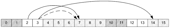
- the first line represents a time slot in a radio frame, the time slot includes an uplink time slot, a downlink time slot and a special time slot; the first column represents a subframe configuration mode of the TDD system; A x, y represents: in the configuration In mode y, the slot x is used to feed back the reception status information of the downlink data transmitted on the slot xA x,y .
- time slot 0 time slot 1
- time slot 10 time slot 11
- time slot 2 time slot 3
- time slot 12 and time slot 13 are all special time slots.
- Time slot 4 time slot 5, time slot 6, time slot 7, time slot 8, time slot 9, time slot 14, time slot 15, time slot 16, time slot 17, time slot 18, time slot 19 are all uplinks Time slot.
- the time slot 4, the time slot 9, the time slot 14 and the time slot 19 are not used for feeding back the receiving state information of the downlink data
- the time slot 5 is used for feeding back the receiving state of the downlink data sent on the time slot 0 of the current radio frame.
- slot 6 is used to feed back the reception status information of the downlink data transmitted on slot 1 in the current radio frame
- slot 7 is used to feed back the downlink data transmitted on slot 2 in the current radio frame.
- Receiving status information time slot 8 is used to feed back the reception status information of the downlink data transmitted on the time slot 3 of the current radio frame
- time slot 15 is used for feedback.
- Receive state information of downlink data transmitted on the time slot 10 in the current radio frame the time slot 16 is used to feed back the reception state information of the downlink data transmitted on the time slot 11 in the current radio frame
- the time slot 17 is used for feedback.
- the reception status information of the downlink data transmitted on the time slot 12 in the current radio frame is used to feed back the reception status information of the downlink data transmitted on the time slot 13 in the current radio frame.
- Other configurations are similar to the configuration mode 0, and the embodiments of the present invention are not described herein again.
- the shortest timing of the first time interval is k
- the shortest timing of the second time interval is ki. This can reduce the feedback delay.
- the uplink time slot 7 can be carried on the time slot 2 at this time.
- the uplink time slot 7 may not carry the reception status information of the downlink data transmitted on the time slot 3, and the reception status information of the downlink data transmitted on the time slot 3 may pass the uplink time slot 14 Feedback, this will cause a large delay.
- the uplink time slot 7 can be used to carry the receiving state information of the downlink data transmitted on the time slot 3, thus reducing the feedback delay.
- the terminal device sends the receiving state information of the first downlink data in the uplink time slot m, and transmits the receiving state information of the second downlink data in the uplink time slot n.
- the start position of the uplink time slot m and the start position of the first time interval are at least k time slots, and the start position of the uplink time slot n and the start position of the second time interval are at least ki.
- k is an integer greater than or equal to 1, and less than or equal to 8
- i is a non-negative integer less than k.
- the terminal device may feed back the reception status information of the first downlink data and the second downlink data on the uplink time slot.
- the terminal device may feed back the receiving status information of the first downlink data on the uplink time slot m of at least k time slots between the actual position and the starting position of the first time interval, and may be at the starting position and the second time interval.
- the receiving state information of the second downlink data is fed back to the time slot m of at least ki time slots between the starting positions.
- the terminal device may send the first downlink data and the second downlink data in the time slot 7 according to the redefined HARQ time slot. status information.
- the base station receives the receiving state information of the first downlink data in the uplink time slot m, and receives the receiving state information of the second downlink data in the uplink time slot n.
- step 405 may be performed.
- the base station sends retransmission data on the second time interval.
- the terminal device For the retransmission data sent on the second time interval, the terminal device performs the following step 406 before receiving the retransmission data.
- the terminal device determines whether the number of symbols included in the second time interval is not less than a preset threshold.
- the terminal device may determine, before the terminal device receives the retransmission data, whether the number of symbols included in the second time interval is not less than a preset threshold, and if the number of symbols included in the second time interval is not less than a preset threshold, executing In the following steps 407 and 408, if the number of symbols included in the second time interval is less than the preset threshold, the following steps 409 and 410 are performed.
- the terminal device receives the retransmission data on the second time interval.
- the terminal device sends the receiving status information of the retransmitted data on the time slot s according to whether the receiving is correct or not. If the retransmission data is received correctly, the receiving status information is ACK, and if the retransmission data is received incorrectly, the receiving status information is NACK.
- the terminal device does not receive the retransmission data on the second time interval.
- the terminal device sends the receiving status information of the retransmitted data on the time slot s, where the receiving status information is a NACK.
- the start position of the uplink time slot s and the start position of the second time interval are at least ki time slots
- k is an integer greater than or equal to 1, and less than or equal to 8
- i is a non-negative less than k Integer.
- the base station sends the first downlink data at the first time interval, and sends the second downlink data at the second time interval, where the second time interval is located in the first special subframe.
- the first time slot of the two time slots or the second special subframe enables efficient use of all symbols in the DwPTS included in the special subframe for downlink data transmission, thereby avoiding waste of transmission resources.
- DwPTS in a special subframe occupies 6 symbols
- GP occupies 2 symbols
- UpPTS occupies 6 symbols.
- the UpPTS includes only the Physical Uplink Shared Channel (PUSCH) and the sounding reference signal. How to enable the UpPTS bearer to receive the feedback information of the state information has become a key topic in the field.
- the present invention uses the UpPTS to carry back feedback of partial reception status information in the uplink control channel transmission method shown in FIG.
- FIG. 23 is a flowchart of a method for transmitting an uplink control channel according to an embodiment of the present invention. The method is applied to a TDD system. As shown in FIG. 23, the method may include:
- the network device sends third downlink data on the first time slot.
- the downlink data that needs to be sent may be sent on the first time slot.
- the terminal device receives the third downlink data on the first time slot.
- the terminal device sends an uplink physical control channel on the second time slot, where the uplink physical control channel is used to carry the receiving state information of the third downlink data, the uplink physical control channel is located in the UpPTS included in the special subframe, and the UpPTS includes six symbols. .
- the second time slot is the time slot in which the UpPTS is located, and the start position of the first time slot and the start position of the time slot in which the UpPTS is located are at least k time slots, and k is greater than or equal to 1, and less than or equal to 8 The integer.
- the terminal device may An uplink physical control channel for carrying the reception status information of the third downlink data is sent on the time slot where the UpPTS is located.
- the terminal device may first determine the number of physical channel units that constitute the uplink physical control channel, and determine the structure of the uplink physical control channel according to the number of physical channel units, and finally, according to The structure of the determined uplink physical control channel generates an uplink physical control channel.
- the demodulation reference signal is used by the base station to perform uplink channel estimation, and the control signaling is used to carry HARQ-ACK information, where the HARQ-ACK information is used to indicate the receiving status of the downlink data, and the receiving status includes the following: At least two types: ACK, NACK, and DTX, and frequency hopping is used to indicate whether all physical channel units are located in multiple frequency bands.
- the structure of the uplink physical control channel is exemplified by the structure of the uplink physical control channel.
- the shaded portion in FIG. 23B is used to carry bearer HARQ-ACK information.
- the feedback of the reception state information of the received downlink data using the HARQ sequence shown in Table 5 is similar to the feedback of the reception state information of the received downlink data by using the HARQ timing shown in Table 3 of another embodiment of the present invention, and the present invention is similar to the present invention.
- the embodiments are not described in detail herein.
- Table 5 and Table 3 it can be obtained that by using the feedback of the UpPTS bearer receiving status information, the load of other uplink time slots can be effectively reduced.
- the network device receives the uplink physical control channel on the second time slot.
- the uplink control channel transmission method provided by the embodiment of the present invention uses UpPTS bearer Part of the feedback work of receiving status information. Moreover, by using the feedback of the status information received by the UpPTS bearer part, the load of other uplink time slots is effectively reduced.
- each network element such as a network device and a terminal device, in order to implement the above functions, includes hardware structures and/or software modules corresponding to each function.
- the present invention can be implemented in a combination of hardware or hardware and computer software in combination with the algorithm steps of the various examples described in the embodiments disclosed herein. Whether a function is implemented in hardware or computer software to drive hardware depends on the specific application and design constraints of the solution. A person skilled in the art can use different methods for implementing the described functions for each particular application, but such implementation should not be considered to be beyond the scope of the present invention.
- the embodiment of the present invention may divide the function module into the network device according to the foregoing method example.
- each function module may be divided according to each function, or two or more functions may be integrated into one processing module.
- the above integrated modules can be implemented in the form of hardware or in the form of software functional modules. It should be noted that the division of the module in the embodiment of the present invention is schematic, and is only a logical function division, and the actual implementation may have another division manner.
- FIG. 24 is a schematic diagram showing a possible configuration of the network device involved in the foregoing embodiment.
- the network device may include: a sending unit 61. .
- the sending unit 61 is configured to support the network device to perform step 401 in the data transmission method shown in FIG. 16 and perform step 501 in the uplink control channel transmission method shown in FIG. 23.
- the network device may further include: a receiving unit 62.
- the receiving unit 62 is configured to support the network device to perform step 404 in the data transmission method shown in FIG. 16 and perform step 504 in the uplink control channel transmission method shown in FIG. 23.
- the network device provided by the embodiment of the present invention is configured to perform the foregoing data transmission method, so that the same effect as the foregoing data transmission method can be achieved, or the method for transmitting the control channel is performed, and thus the transmission method of the control channel can be achieved. Effect.
- FIG. 25 shows another possible composition diagram of the network device involved in the above embodiment.
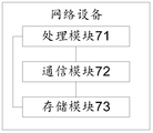
- the network device includes a processing module 71 and a communication module 72.
- the processing module 71 is for controlling management of the actions of the network device, and/or other processes for the techniques described herein.
- Communication module 72 is used to support communication of network devices with other network entities, such as communications with the functional modules or network entities shown in FIG. 15, FIG. 26, or FIG. For example, in step 401 and step 404 for supporting the network device to execute the data transmission method shown in FIG. 16, step 501 and step 504 in the uplink control channel transmission method shown in FIG. 23 are performed.
- the network device may further include a storage module 73 for storing program codes and data of the network device.
- the processing module 71 can be a processor or a controller. It is possible to implement or carry out the various illustrative logical blocks, modules and circuits described in connection with the present disclosure.
- the processor can also be a combination of computing functions, for example, including one or more microprocessor combinations, a combination of a DSP and a microprocessor, and the like.
- the communication module 72 can be a transceiver, a transceiver circuit, a communication interface, or the like.
- the storage module 73 can be a memory.
- the network device involved in the embodiment of the present invention may be the network device shown in FIG.
- the embodiment of the present invention may divide the function module into the terminal device according to the foregoing method example.
- each function module may be divided according to each function, or two or more functions may be integrated into one processing module.
- the above integrated modules can be implemented in the form of hardware or in the form of software functional modules. It should be noted that the division of the module in the embodiment of the present invention is schematic, and is only a logical function division, and the actual implementation may have another division manner.
- FIG. 26 is a schematic diagram showing a possible configuration of the terminal device involved in the foregoing and the embodiment.
- the terminal device may include: a receiving unit 81. .
- the receiving unit 81 is configured to support the terminal device to perform step 402 and step 406 in the data transmission method shown in FIG. 16 and perform step 502 in the uplink control channel transmission method shown in FIG. 23.
- the terminal device may further include: a sending unit 82 and a determining unit 83.
- the transmitting unit 82 is configured to support the terminal device to perform step 403 and step 407 in the data transmission method shown in FIG. 16 and perform step 503 in the uplink control channel transmission method shown in FIG. 23.
- the determining unit 83 is configured to support the terminal device to perform step 405 in the data transmission method shown in FIG. 16.
- the terminal device provided by the embodiment of the present invention is configured to perform the foregoing data transmission method, so that the same effect as the foregoing data transmission method can be achieved, or the method for transmitting the control channel is performed, and thus the transmission method of the control channel can be achieved. Effect.
- FIG. 27 shows another possible composition diagram of the terminal device involved in the above embodiment.
- the terminal device includes a processing module 91 and a communication module 92.
- the processing module 91 is configured to control and manage the actions of the terminal device, for example, to support the terminal device to perform step 405 in the data transmission method shown in FIG. 16, and/or other processes for the techniques described herein.
- Communication module 92 is used to support communication between the terminal device and other network entities, such as communication with the functional modules or network entities shown in FIG. 14, FIG. 24, or FIG.
- step 502 and step 503 in the uplink control channel transmission method shown in FIG. 23 are executed to support the terminal device to perform step 402, step 403, step 406, and step 407 in the data transmission method shown in FIG. End
- the end device may further include a storage module 93 for storing program codes and data of the terminal device.
- the processing module 91 can be a processor or a controller. It is possible to implement or carry out the various illustrative logical blocks, modules and circuits described in connection with the present disclosure.
- the processor can also be a combination of computing functions, for example, including one or more microprocessor combinations, a combination of a DSP and a microprocessor, and the like.
- the communication module 92 can be a transceiver, a transceiver circuit, a communication interface, or the like.
- the storage module 93 can be a memory.
- the terminal device When the processing module 91 is a processor, the communication module 92 is a transceiver, and the storage module 93 is a memory, the terminal device according to the embodiment of the present invention may be the terminal device shown in FIG.
- the terminal device provided by the embodiment of the present invention is configured to perform the foregoing data transmission method, so that the same effect as the foregoing data transmission method can be achieved, or the method for transmitting the control channel is performed, and thus the transmission method of the control channel can be achieved. Effect.
- the disclosed apparatus and method may be implemented in other manners.
- the device embodiments described above are merely illustrative.
- the division of the modules or units is only a logical function division.
- there may be another division manner for example, multiple units or components may be used.
- the combination may be integrated into another device, or some features may be ignored or not performed.
- the mutual coupling or direct coupling or communication connection shown or discussed may be an indirect coupling or communication connection through some interface, device or unit, and may be in an electrical, mechanical or other form.
- the units described as separate components may or may not be physically separated, and the components displayed as units may be one physical unit or multiple physical units, that is, may be located in one place, or may be distributed to multiple different places. . Some or all of the units may be selected according to actual needs to achieve the purpose of the solution of the embodiment.
- each functional unit in each embodiment of the present invention may be integrated into one processing unit, or each unit may exist physically separately, or two or more units may be integrated into one unit.
- the above integrated unit can be implemented in the form of hardware or in the form of a software functional unit.
- the integrated unit if implemented in the form of a software functional unit and sold or used as a standalone product, may be stored in a readable storage medium. Based on such understanding, the technical solution of the embodiments of the present invention may contribute to the prior art or all or part of the technical solution may be embodied in the form of a software product stored in a storage medium. A number of instructions are included to cause a device (which may be a microcontroller, chip, etc.) or a processor to perform all or part of the steps of the methods described in various embodiments of the present invention.
- the foregoing storage medium includes: a U disk, a mobile hard disk, a read only memory (English: Read-Only Memory, abbreviated as: ROM), a random access memory (English: Random Access Memory, abbreviated as: RAM), a magnetic disk or an optical disk, and the like.
- ROM Read-Only Memory
- RAM Random Access Memory
Abstract
本发明实施例公开了一种数据传输方法及设备,涉及通信领域,解决了仅用DwPTS包含的部分符号进行下行数据的传输造成的传输资源浪费的问题。具体方案为:网络设备在第二时间间隔上发送第二下行数据,其中,第二时间间隔位于第一特殊子帧中的第二个时隙或第二特殊子帧中的第一个时隙,第一特殊子帧为下行导频时隙持续时间大于0.5毫秒的特殊子帧,第二特殊子帧为下行导频时隙持续时间小于0.5毫秒的特殊子帧,第二时间间隔包含N个符号,N为大于或等于2,且小于或等于6的整数。本发明实施例用于数据传输的过程中。
Description
本发明实施例涉及通信领域,尤其涉及一种数据传输方法及设备。
长期演进(Long Term Evolution,LTE)系统分为频分双工系统和时分双工(Time Division Duplex,TDD)系统。TDD系统定义的帧结构如图1所示,具体的,一个10毫秒(ms)的无线帧由10个1ms的子帧构成,其中包括至少一个下行子帧,至少一个上行子帧和至少一个特殊子帧,下行子帧可以用来进行下行数据的传输,上行子帧可以用来进行上行数据的传输,特殊子帧包括下行导频时隙(Downlink Pilot TimeSlot,DwPTS)、保护间隔(Guard Period,GP)和上行导频时隙(Uplink Pilot TimeSlot,UpPTS)。并且,TDD系统为特殊子帧设计了不同的配置,如在TDD系统采用常规循环前缀(Cyclic Prefix,CP)(在TDD系统采用常规CP时一个子帧包含14个符号)时,特殊子帧的配置如表1所示,表1中示出了不同配置下DwPTS和UpPTS分别占的符号个数。
表1

另外,随着新业务对时延要求的提高,TDD系统中引入了时延降低(Latency Reduction)技术,其将传统的一个子帧的传输时间间隔(transmission time interval,TTI)缩短至半个子帧(1个时隙)的短传输时间间隔(shortened TTI,sTTI)。
在引入了时延降低技术的TDD系统中,以TDD系统采用常规
CP为例,现有技术针对表1中除#0、#5和#9外的配置提供了一种采用特殊子帧包括的DwPTS传输下行数据的方案。具体的,如图2所示,该方案将特殊子帧包括的DwPTS分为两部分,第一部分包含7个符号,即第一部分的持续时间为1个时隙(1个时隙等于0.5ms),第二部分包含剩余的Z个符号(Z为大于或等于2,且小于或等于5的整数),且,仅用DwPTS包含的第一部分传输下行数据,第二部分被舍弃不用于下行数据的传输。现有技术中仅用DwPTS包含的部分符号进行下行数据的传输,会造成传输资源的浪费。
发明内容
本发明实施例提供一种帧结构及其数据传输方法和设备,解决了仅用DwPTS包含的部分符号进行下行数据的传输造成的传输资源浪费的问题。
为达到上述目的,本发明实施例采用如下技术方案:
本发明实施例的第一方面,提供一种数据传输方法,应用于TDD系统,包括:
网络设备在位于第一特殊子帧中的第二个时隙或第二特殊子帧中的第一个时隙的第二时间间隔上发送第二下行数据,其中,第一特殊子帧为下行导频时隙持续时间大于0.5毫秒的特殊子帧,第二特殊子帧为下行导频时隙持续时间小于0.5毫秒的特殊子帧,第二时间间隔包含N个符号,N为大于或等于2,且小于或等于6的整数。
其中,当TDD系统采用常规CP时,第二时间间隔包含N个符号,N为大于或等于2,且小于或等于6的整数;当TDD系统采用扩展CP时,第二时间间隔包含M个符号,M为大于或等于2,且小于或等于5的整数。
本发明实施例提供的数据传输方法,网络设备在第一时间间隔上发送第一下行数据,在第二时间间隔上发送第二下行数据,该第二时间间隔位于第一特殊子帧中的第二个时隙或第二特殊子帧中的第一个时隙,使得能够有效利用特殊子帧包括的DwPTS中的所有符
号进行下行数据的传输,避免了传输资源的浪费。
结合第一方面,在一种可能的实现方式中,本发明实施例提供的数据传输方法还可以包括:网络设备在位于第一特殊子帧中的第一个时隙的第一时间间隔上发送第一下行数据。
其中,当TDD系统采用常规CP时,第一时间间隔包含7个符号;当TDD系统采用扩展CP时,第一时间间隔包含6个符号。
结合第一方面和上述可能的实现方式,在另一种可能的实现方式中,为了增加第二时间间隔承载的数据量,本发明实施例提供的数据传输方法还可以包括:网络设备发送包含有用于指示第二下行数据传输的控制信息的第二下行控制信息(Downlink Control Information,DCI),该第二DCI位于第一特殊子帧中的第一个时隙,或者该第二DCI位于第二特殊子帧之前,且与第二特殊子帧相邻的时隙。
结合第一方面和上述可能的实现方式,在另一种可能的实现方式中,本发明实施例提供的数据传输方法还可以包括:网络设备发送包含有用于指示第一下行数据传输的控制信息的第一DCI,该第一DCI位于第一特殊子帧中的第一个时隙。
结合第一方面和上述可能的实现方式,在另一种可能的实现方式中,包含有用于指示第二下行数据传输的控制信息的第二DCI,还包含用于指示第一下行数据传输的调度信息。
结合第一方面和上述可能的实现方式,在另一种可能的实现方式中,为了有效降低反馈时延,在网络设备在第二时间间隔上发送第二下行数据之后,本发明实施例提供的数据传输方法还可以包括:网络设备在上行时隙n接收第二下行数据的接收状态信息,该上行时隙n的起始位置和第二时间间隔的起始位置之间至少相距k-i个时隙,其中,k为大于或等于1,且小于或等于8的整数,i为小于k的非负整数。
结合第一方面和上述可能的实现方式,在另一种可能的实现方式中,在网络设备在第一时间间隔上发送第一下行数据之后,本发
明实施例提供的数据传输方法还可以包括:网络设备在上行时隙m接收第一下行数据的接收状态信息,该上行时隙m的起始位置和第一时间间隔的起始位置之间至少相距k个时隙,其中,k为大于或等于1,且小于或等于8的整数。
本发明实施例的第二方面,提供一种数据传输方法,应用于TDD系统,包括:
终端设备在位于第一特殊子帧中的第二个时隙或第二特殊子帧中的第一个时隙的第二时间间隔上接收第二下行数据,其中,第一特殊子帧为下行导频时隙持续时间大于0.5毫秒的特殊子帧,第二特殊子帧为下行导频时隙持续时间小于0.5毫秒的特殊子帧,第二时间间隔包含N个符号,N为大于或等于2,且小于或等于6的整数。
本发明实施例提供的数据传输方法,终端设备在第一时间间隔上接收第一下行数据,在第二时间间隔上接收第二下行数据,该第二时间间隔位于第一特殊子帧中的第二个时隙或第二特殊子帧中的第一个时隙,使得能够有效利用特殊子帧包括的DwPTS中的所有符号进行下行数据的传输,避免了传输资源的浪费。
结合第二方面,在一种可能的实现方式中,本发明实施例提供的数据传输方法还可以包括:终端设备在位于第一特殊子帧中的第一个时隙的第一时间间隔上接收第一下行数据。
结合第二方面和上述可能的实现方式,在另一种可能的实现方式中,为了增加第二时间间隔承载的数据量,本发明实施例提供的数据传输方法还可以包括:终端设备接收包含有用于指示第二下行数据传输的控制信息的第二DCI,该第二DCI位于第一特殊子帧中的第一个时隙,或者该第二DCI位于第二特殊子帧之前,且与第二特殊子帧相邻的时隙。
结合第二方面和上述可能的实现方式,在另一种可能的实现方式中,本发明实施例提供的数据传输方法还可以包括:终端设备接收包含有用于指示第一下行数据传输的控制信息的第一DCI,该第
一DCI位于第一特殊子帧中的第一个时隙。
结合第二方面和上述可能的实现方式,在另一种可能的实现方式中,包含有用于指示第二下行数据传输的控制信息的第二DCI,还包含用于指示第一下行数据传输的调度信息。
结合第二方面和上述可能的实现方式,在另一种可能的实现方式中,为了降低反馈时延,在终端设备在第二时间间隔上接收第二下行数据之后,本发明实施例提供的数据传输方法还可以包括:终端设备在上行时隙n发送第二下行数据的接收状态信息,该上行时隙n的起始位置和第二时间间隔的起始位置之间至少相距k-i个时隙,其中,k为大于或等于1,且小于或等于8的整数,i为小于k的非负整数。
结合第二方面和上述可能的实现方式,在另一种可能的实现方式中,在终端设备在第一时间间隔上接收第一下行数据之后,本发明实施例提供的数据传输方法还可以包括:终端设备在上行时隙m发送第一下行数据的接收状态信息,该上行时隙m的起始位置和第一时间间隔的起始位置之间至少相距k个时隙,其中,k为大于或等于1,且小于或等于8的整数。
结合第二方面和上述可能的实现方式,在另一种可能的实现方式中,为了节约终端设备的检测成本,当终端设备需在第二时间间隔上接收重传数据时,本发明实施例提供的数据传输方法还可以包括:终端设备判断第二时间间隔包含的符号个数是否不小于预设阈值,若确定出第二时间间隔包含的符号个数小于预设阈值,则终端设备不接收重传数据,并在上行时隙s发送重传数据的非确认(Non-Acknowledgement,NACK)的接收状态信息,其上行时隙s的起始位置和第二时间间隔的起始位置之间至少相距k-i个时隙,k为大于或等于1,且小于或等于8的整数,i为小于k的非负整数;若确定出第二时间间隔包含的符号个数不小于预设阈值,则终端设备在第二时间间隔上接收重传数据。
本发明实施例的第三方面,提供一种上行控制信道传输方法,
应用于TDD系统,包括:
网络设备在第一时隙上发送第三下行数据,并在第二时隙上接收用于承载第三下行数据的接收状态信息的上行物理控制信道,该上行物理控制信道位于特殊子帧包括的UpPTS内,UpPTS包含6个符号。
本发明实施例提供的上行控制信道传输方法,利用UpPTS承载了部分接收状态信息的反馈工作。并且,通过利用UpPTS承载部分接收状态信息的反馈,有效的降低了其他上行时隙的负载量。
结合第三方面,在一种可能的实现方式中,第二时隙为UpPTS所在时隙,第一时隙的起始位置与UpPTS所在时隙的起始位置之间至少相距k个时隙,其中,k为大于或等于1,且小于或等于8的整数。
本发明实施例的第四方面,提供一种上行控制信道传输方法,应用于TDD系统,包括:
终端设备在第一时隙上接收第三下行数据,并在第二时隙上发送用于承载第三下行数据的接收状态信息的上行物理控制信道,该上行物理控制信道位于特殊子帧包括的UpPTS内,UpPTS包含6个符号。
本发明实施例提供的上行控制信道传输方法,利用UpPTS承载了部分接收状态信息的反馈工作。并且,通过利用UpPTS承载部分接收状态信息的反馈,有效的降低了其他上行时隙的负载量。
结合第四方面,在一种可能的实现方式中,第二时隙为UpPTS所在时隙,第一时隙的起始位置与UpPTS所在时隙的起始位置之间至少相距k个时隙,其中,k为大于或等于1,且小于或等于8的整数。
本发明实施例的第五方面,提供一种网络设备,应用于TDD系统,该网络设备可以包括:
发送单元,用于在第二时间间隔上发送第二下行数据,其中,第二时间间隔位于第一特殊子帧中的第二个时隙或第二特殊子帧中
的第一个时隙,第一特殊子帧为下行导频时隙持续时间大于0.5毫秒的特殊子帧,第二特殊子帧为下行导频时隙持续时间小于0.5毫秒的特殊子帧,第二时间间隔包含N个符号,N为大于或等于2,且小于或等于6的整数。
结合第五方面,在一种可能的实现方式中,发送单元,还用于在位于第一特殊子帧中的第一个时隙的第一时间间隔上发送第一下行数据。
结合第五方面和上述可能的实现方式,在另一种可能的实现方式中,发送单元,还用于发送包含有用于指示第二下行数据传输的控制信息的第二DCI,该第二DCI位于第一特殊子帧中的第一个时隙,或该第二DCI位于第二特殊子帧之前,且与第二特殊子帧相邻的时隙。
结合第五方面和上述可能的实现方式,在另一种可能的实现方式中,发送单元,还用于发送包含有用于指示第一下行数据传输的控制信息的第一DCI,该第一DCI位于第一特殊子帧中的第一个时隙。
结合第五方面和上述可能的实现方式,在另一种可能的实现方式中,发送单元发送的第二DCI还包含用于指示第一下行数据传输的调度信息。
结合第五方面和上述可能的实现方式,在另一种可能的实现方式中,本发明实施例提供的网络设备还可以包括:接收单元。接收单元,用于在上行时隙n接收第二下行数据的接收状态信息,该上行时隙n的起始位置和第二时间间隔的起始位置之间至少相距k-i个时隙,其中,k为大于或等于1,且小于或等于8的整数,i为小于k的非负整数。
结合第五方面和上述可能的实现方式,在另一种可能的实现方式中,本发明实施例提供的网络设备还可以包括:接收单元。接收单元,用于在上行时隙m接收第一下行数据的接收状态信息,该上行时隙m的起始位置和第一时间间隔的起始位置之间至少相距k个
时隙,其中,k为大于或等于1,且小于或等于8的整数。
本发明实施例的第六方面,提供一种终端设备,应用于TDD系统,终端设备包括:
接收单元,用于在第二时间间隔上接收第二下行数据,其中,第二时间间隔位于第一特殊子帧中的第二个时隙或第二特殊子帧中的第一个时隙,且第二时间间隔包含N个符号,N为大于或等于2,且小于或等于6的整数,第一特殊子帧为下行导频时隙持续时间大于0.5毫秒的特殊子帧,第二特殊子帧为下行导频时隙持续时间小于0.5毫秒的特殊子帧。
结合第六方面,在一种可能的实现方式中,接收单元,还用于在第一时间间隔上接收第一下行数据,该第一时间间隔位于第一特殊子帧中的第一个时隙。
结合第六方面和上述可能的实现方式,在另一种可能的实现方式中,接收单元,还用于接收第二DCI,第二DCI包含用于指示第二下行数据传输的控制信息,且第二DCI位于第一特殊子帧中的第一个时隙,或第二DCI位于第二特殊子帧之前,且与第二特殊子帧相邻的时隙。
结合第六方面和上述可能的实现方式,在另一种可能的实现方式中,接收单元,还用于接收第一DCI,第一DCI包含用于指示第一下行数据传输的控制信息,且第一DCI位于第一特殊子帧中的第一个时隙。
结合第六方面和上述可能的实现方式,在另一种可能的实现方式中,接收单元接收到的第二DCI还包含用于指示第一下行数据传输的调度信息。
结合第六方面和上述可能的实现方式,在另一种可能的实现方式中,本发明实施例提供的终端设备还可以包括:发送单元;发送单元,用于在上行时隙n发送第二下行数据的接收状态信息,该上行时隙n的起始位置和第二时间间隔的起始位置之间至少相距k-i个时隙,其中,k为大于或等于1,且小于或等于8的整数,i为小
于k的非负整数。
结合第六方面和上述可能的实现方式,在另一种可能的实现方式中,本发明实施例提供的终端设备还可以包括:发送单元;发送单元,还用于在上行时隙m发送第一下行数据的接收状态信息,该上行时隙m的起始位置和第一时间间隔的起始位置之间至少相距k个时隙,其中,k为大于或等于1,且小于或等于8的整数。
结合第六方面和上述可能的实现方式,在另一种可能的实现方式中,当终端设备需在第二时间间隔上接收重传数据时,终端设备还可以包括:判断单元;判断单元,用于判断第二时间间隔包含的符号个数是否不小于预设阈值;接收单元,还用于若判断单元判断得到第二时间间隔包含的符号个数不小于预设阈值,则在第二时间间隔上接收重传数据;发送单元,还用于若判断单元判断得到第二时间间隔包含的符号个数小于预设阈值,则终端设备不接收重传数据,并在上行时隙s发送重传数据的接收状态信息,接收状态信息为非确认NACK,上行时隙s的起始位置和第二时间间隔的起始位置之间至少相距k-i个时隙,k为大于或等于1,且小于或等于8的整数,i为小于k的非负整数。
本发明实施例的第七方面,提供一种网络设备,应用于TDD系统,该网络设备包括:
发送单元,用于在第一时隙上发送第三下行数据;接收单元,用于在第二时隙上接收上行物理控制信道,上行物理控制信道用于承载第三下行数据的接收状态信息,上行物理控制信道位于特殊子帧包括的UpPTS内,UpPTS包含6个符号。
结合第七方面,在一种可能的实现方式中,第二时隙为UpPTS所在时隙,第一时隙的起始位置与UpPTS所在时隙的起始位置之间至少相距k个时隙,k为大于或等于1,且小于或等于8的整数。
本发明实施例的第八方面,提供一种终端设备,应用于TDD系统,该终端设备包括:
接收单元,用于在第一时隙上接收第三下行数据;发送单元,
用于在第二时隙上发送上行物理控制信道,上行物理控制信道用于承载第三下行数据的接收状态信息,上行物理控制信道位于特殊子帧包括的UpPTS内,UpPTS包含6个符号。
结合第八方面,在一种可能的实现方式中,第二时隙为UpPTS所在时隙,第一时隙的起始位置与UpPTS所在时隙的起始位置之间至少相距k个时隙,k为大于或等于1,且小于或等于8的整数。
本发明实施例的第九方面,提供一种网络设备,应用于TDD系统,该网络设备可以包括:处理器、存储器和收发器;
存储器用于存储计算机执行指令,当网络设备运行时,处理器执行存储器存储的计算机执行指令,以使终端设备执行如第一方面或第一方面的可能的实现方式中任一所述的数据传输方法,或者,执行如第三方面或第三方面的可能的实现方式中任一项所述的上行控制信道传输方法。
本发明实施例的第十方面,提供一种终端设备,应用于TDD系统,该终端设备可以包括:处理器、存储器和收发器;
存储器用于存储计算机执行指令,当终端设备运行时,处理器执行存储器存储的计算机执行指令,以使终端设备执行如第二方面或第二方面的可能的实现方式中任一所述的数据传输方法,或者,执行如第四方面或第四方面的可能的实现方式中任一项所述的上行控制信道传输方法。
本发明实施例的第十一方面,提供一种帧结构,应用于TDD系统,该TDD系统采用sTTI进行数据传输,该帧结构可以包括:
至少一个上行子帧,至少一个下行子帧和至少一个特殊子帧,特殊子帧包括DwPTS、GP和UpPTS,上行子帧、下行子帧和特殊子帧的持续时间均为1毫秒。
当DwPTS的持续时间大于0.5毫秒时,该特殊子帧为第一特殊子帧,第二时间间隔位于第一特殊子帧中的第二个时隙,当DwPTS的持续时间小于0.5毫秒时,该特殊子帧为第二特殊子帧,第二时间间隔位于第二特殊子帧中的第一个时隙;第二时间间隔用于发送
第二下行数据;第二时间间隔包含N个符号,N为大于或等于2,且小于或等于6的整数。
具体的,当TDD系统采用常规CP时,第二时间间隔包含N个符号,N为大于或等于2,且小于或等于5的整数;当TDD系统采用扩展CP时,第二时间间隔包含M个符号,M为大于或等于2,且小于或等于5的整数。
本发明实施例提供的帧结构,可以在第二时间间隔上发送第二下行数据,该第二时间间隔位于第一特殊子帧中的第二个时隙或第二特殊子帧中的第一个时隙,使得能够有效利用特殊子帧包括的DwPTS中的所有符号进行下行数据的传输,避免了传输资源的浪费。
结合第十一方面,在一种可能的实现方式中,当特殊子帧为第一特殊子帧时,第一时间间隔位于第一特殊子帧中的第一个时隙,第一时间间隔用于发送第一下行数据。
其中,当TDD系统采用常规CP时,第一时间间隔包含7个符号;当TDD系统采用扩展CP时,第一时间间隔包含6个符号。
第一时间间隔还用于发送第一下行控制信息DCI和第二DCI,第一DCI包含用于调度第一下行数据的调度信息,第二DCI包含用于调度第二下行数据的调度信息。
结合第十一方面和上述可能的实现方式,在另一种可能的实现方式中,为了增加第二时间间隔承载的数据量,第一特殊子帧中的第一个时隙,或者该位于第二特殊子帧之前,且与第二特殊子帧相邻的时隙用于发送第二DCI,第二DCI包含用于指示第二下行数据传输的控制信息。
结合第十一方面和上述可能的实现方式,在另一种可能的实现方式中,位于第一特殊子帧中的第一个时隙用于发送第一DCI,第一DCI包含用于指示第一下行数据传输的控制信息。
结合第十一方面和上述可能的实现方式,在另一种可能的实现方式中,第二DCI还包含用于指示第一下行数据传输的调度信息。
结合第十一方面和上述可能的实现方式,在另一种可能的实现
方式中,对于上行时隙q,若上行时隙q用于反馈在第一时间间隔上发送的第一下行数据的接收状态信息,则第一时间间隔位于时隙q-k或位于时隙q-k之前;若时隙q用于反馈在第二时间间隔上发送的第二下行数据的接收状态信息,则第二时间间隔位于时隙q-k+i或位于时隙q-k+i之前,k为大于或等于1,且小于或等于8的整数,i为小于k的非负整数。
为了更清楚地说明本发明实施例或现有技术中的技术方案,下面将对实施例或现有技术描述中所需要使用的附图作简单地介绍,显而易见地,下面描述中的附图仅仅是本发明的一些实施例,对于本领域普通技术人员来讲,在不付出创造性劳动性的前提下,还可以根据这些附图获得其他的附图。
图1为现有技术提供的一种帧结构示意图;
图2为现有技术提供的特殊子帧的结构示意图;
图3为本发明实施例提供的一种帧结构示意图;
图4为本发明实施例提供的另一种帧结构示意图;
图5为本发明实施例提供的另一种帧结构示意图;
图6为本发明实施例提供的另一种帧结构示意图;
图7为本发明实施例提供的另一种帧结构示意图;
图8为本发明实施例提供的另一种帧结构示意图;
图9为本发明实施例提供的另一种帧结构示意图;
图10为本发明实施例提供的另一种帧结构示意图;
图11为本发明实施例提供的另一种帧结构示意图;
图12为本发明实施例提供的另一种帧结构示意图;
图13为本发明实施例提供的一种应用本发明实施例的无线通信系统的简化示意图;
图14为本发明实施例提供的一种网络设备的组成示意图;
图15为本发明实施例提供的一种终端设备的组成示意图;
图16为本发明实施例提供的一种数据传输方法的流程图;
图17为本发明实施例提供的另一种帧结构示意图;
图18为本发明实施例提供的另一种帧结构示意图;
图19为本发明实施例提供的另一种帧结构示意图;
图20为本发明实施例提供的另一种帧结构示意图;
图20A为本发明实施例提供的另一种帧结构示意图;
图21为本发明实施例提供的一种子帧配置示意图;
图22为本发明实施例提供的一种下行数据的接收状态信息的反馈示意图;
图23A为本发明实施例提供的一种特殊子帧的结构示意图;
图23为本发明实施例提供的一种上行控制信道传输方法的流程图;
图23B为本发明实施例提供的一种上行物理控制信道的结构示意图;
图24为本发明实施例提供的另一种网络设备的组成示意图;
图25为本发明实施例提供的另一种网络设备的组成示意图;
图26为本发明实施例提供的另一种终端设备的组成示意图;
图27为本发明实施例提供的另一种终端设备的组成示意图。
下面将结合本发明实施例中的附图,对本发明实施例中的技术方案进行清楚、完整地描述,显然,所描述的实施例仅仅是本发明一部分实施例,而不是全部的实施例。基于本发明中的实施例,本领域普通技术人员在没有作出创造性劳动前提下所获得的所有其他实施例,都属于本发明保护的范围。
其中,本文中术语“系统”和“网络”在本文中常被可互换使用。本文中术语“和/或”,仅仅是一种描述关联对象的关联关系,表示可以存在三种关系,例如,A和/或B,可以表示:单独存在A,同时存在A和B,单独存在B这三种情况。另外,本文中字符“/”,一般表示前后关联对象是一种“或”的关系。
为了避免传输资源的浪费。本发明提供一种数据传输方法,其
具体方案为:网络设备在第二时间间隔上发送第二下行数据,该第二时间间隔位于第一特殊子帧中的第二个时隙或第二特殊子帧中的第一个时隙,第一特殊子帧为下行导频时隙持续时间大于0.5毫秒的特殊子帧,第二特殊子帧为下行导频时隙持续时间小于0.5毫秒的特殊子帧,第二时间间隔包含N个符号,N为大于或等于2,且小于或等于6的整数。通过采用位于第一特殊子帧中第二个时隙或者位于第二特殊子帧中第一个时隙的第二时间间隔发送第二下行数据,可以有效利用特殊子帧包括的DwPTS中的所有符号进行下行数据的传输,避免了传输资源的浪费。
为了便于本领域技术人员的理解,本发明实施例在此对本发明实施例中涉及到的基本术语进行说明。
(1)、子帧n-a和子帧n+a:在LTE系统中,每个无线帧由10个1ms的子帧构成,该10个子帧的编号可以为0~9,具体的为:子帧0、子帧1、子帧2、子帧3、子帧4、子帧5、子帧6、子帧7、子帧8、子帧9。
其中,子帧n-a指的是位于子帧n之前的第a个子帧,即子帧n-a指的是从子帧n开始往前数的第a个子帧。例如,如图3所示,若n=4,a=2,则子帧n-a是子帧4所在无线帧中的子帧2。再例如,如图4所示,若n=0,a=2,则子帧n-a是子帧0所在无线帧的上一个无线帧中的子帧8。
子帧n+a指的是位于子帧n之后的第a个子帧,即子帧n+a指的是从子帧n开始往后数的第a个子帧。例如,如图5所示,若n=4,a=3,则子帧n+a是子帧4所在无线帧中的子帧7。再例如,如图6所示,若n=8,a=2,则子帧n+a是子帧8所在无线帧的下一个无线帧中的子帧0。
(2)、时隙n-a和时隙n+a:在LTE系统中,每个子帧包括2个持续时间为0.5ms的时隙(slot),即每个无线帧包括20个时隙,该20个时隙的编号可以为0~19,具体的为:时隙0、时隙1、时隙2、时隙3、时隙4、时隙5、时隙6、时隙7、时隙8、时隙9、时
隙10、时隙11、时隙12、时隙13、时隙14、时隙15、时隙16、时隙17、时隙18、时隙19。
其中,时隙n-a指的是位于时隙n之前的第a个时隙,即时隙n-a指的是从时隙n开始往前数的第a个时隙。例如,如图7所示,若n=4,a=2,则时隙n-a是时隙4所在无线帧中的时隙2。再例如,如图8所示,若n=0,a=2,则时隙n-a是时隙0所在无线帧的上一个无线帧中的时隙18。
时隙n+a指的是位于时隙n之后的第a个时隙,即时隙n+a指的是从时隙n开始往后数的第a个时隙。例如,如图9所示,n=4,a=3,则时隙n+a是时隙4所在无线帧中的时隙7。再例如,如图10所示,若n=18,a=2,则时隙n+a是时隙18所在无线帧的下一个无线帧中的时隙0。
(3)、符号:在本发明实施例中上行符号和下行符号都简称为符号。
其中,上行符号称为单载波频分多址(single carrier-frequency division multiple access,SC-FDMA)符号,下行符号称为正交频分多址(orthogonal frequency division multiplexing,OFDM)符号。需要说明的是,若引入正交频分多址(Orthogonal Frequency Division Multiple Access,OFDMA)的上行多址方式,上行符号也可以称为其他类型符号,例如OFDM符号。且本发明实施例对于上行多址方式和下行多址方式不做具体限制。
在TDD系统中,每个slot包括的符号的个数与该TDD系统采用的CP的长度相关。如果CP为常规CP,那么每个slot包括7个符号,每个子帧由14个符号组成。例如,每个子帧由序号分别为#0,#1,#2,#3,#4,#5,#6,#7,#8,#9,#10,#11,#12,#13的符号组成。如果CP为扩展CP,那么每个slot包括6个符号,每个子帧由12个符号组成。例如,每个子帧由序号分别为#0,#1,#2,#3,#4,#5,#6,#7,#8,#9,#10,#11的符号组成。
(4)、混合自动重传请求(Hybrid Automatic Repeat Request,
HARQ)时序:HARQ时序指的是下行数据传输与终端设备的混合自动重传请求确认(HARQ acknowledgement,HARQ-ACK)反馈之间的传输时间顺序。
需要说明的是,在本发明实施例应用于TDD系统,并且,该TDD系统采用sTTI进行数据传输。该TDD系统的帧结构包括:至少一个上行子帧、至少一个下行子帧和至少一个特殊子帧,特殊子帧包括DwPTS、GP和UpPTS,上行子帧、下行子帧和特殊子帧的持续时间均为1毫秒。其中,当DwPTS的持续时间大于0.5毫秒时,包含该DwPTS的特殊子帧可以称为第一特殊子帧,当DwPTS的持续时间小于0.5毫秒时,包含该DwPTS的特殊子帧可以称为第二特殊子帧。本发明实施例中涉及到的第一时间间隔位于第一特殊子帧中的第一个时隙,第二时间间隔位于第一特殊子帧中的第二个时隙,或者,位于第二特殊子帧中的第一个时隙,也就是说,当特殊子帧包括的DwPTS的持续时间大于0.5毫秒时,该特殊子帧包括一个第一时间间隔和一个第二时间间隔,当特殊子帧包括的DwPTS的持续时间小于0.5毫秒时,该特殊子帧包括一个第二时间间隔,不包括第一时间间隔。本发明实施例采用该帧结构进行数据传输。
其中,当TDD系统采用常规CP时,第一时间间隔包含7个符号,第二时间间隔包含N个符号,N为大于或等于2,且小于或等于6的整数;当TDD系统采用扩展CP时,第一时间间隔包含6个符号,第二时间间隔包含M个符号,M为大于或等于2,且小于或等于5的整数。
示例性的,在如图11所示的帧结构中,包括4个上行子帧、4个下行子帧和2个特殊子帧,且特殊子帧包括的DwPTS的持续时间大于0.5毫秒,其中,针对2个特殊子帧中的每个特殊子帧,第一时间间隔位于该特殊子帧中的第一个时隙,第二时间间隔位于该特殊子帧中的第二个时隙。示例性的,在如图12所示的帧结构中,包括4个上行子帧、4个下行子帧和2个特殊子帧,且特殊子帧包括的DwPTS的持续时间小于0.5毫秒,其中,针对2个特殊子帧中的
每个特殊子帧,第二时间间隔位于该特殊子帧中的第一个时隙,该特殊子帧中不包括第一时间间隔。
下面将结合附图对本发明实施例的实施方式进行详细描述。
如图13所示,图13示出的是可以应用本发明实施例的无线通信系统的简化示意图。该无线通信系统可以包括:网络设备11和终端设备12。
其中,该无线通信系统支持TDD,如4.5G或5G通信,该网络设备11和终端设备12之间采用sTTI进行数据传输。
网络设备11可以是无线通信的基站(Base Station,BS)或基站控制器等。网络设备11是一种部署在无线接入网中用以为终端设备12提供无线通信功能的装置,其主要功能有:进行无线资源的管理、互联网协议(Internet Protocol,IP)头的压缩及用户数据流的加密、终端设备12附着时进行移动管理实体(Mobile Management Entity,MME)的选择、路由用户面数据至服务网关(Service Gateway,SGW)、寻呼消息的组织和发送、广播消息的组织和发送、以移动性或调度为目的的测量及测量报告的配置等等。网络设备11可以包括各种形式的宏基站、微基站、中继站、接入点等等。在采用不同的无线接入技术的系统中,具备基站功能的设备的名称可能会有所不同。例如,在LTE系统中,称为演进的节点B(evolved NodeB,eNB或eNodeB),在第3代移动通信技术(The 3rd Generation Telecommunication,3G)系统中,称为节点B(Node B)等等。随着通信技术的演进,“基站”这一名称可能会变化。此外,在其它可能的情况下,网络设备11可以是其它为终端设备12提供无线通信功能的装置。为方便描述,本发明实施例中,为终端设备12提供无线通信功能的装置称为网络设备11。
终端设备12可以包括各种具有无线通信功能的手持设备(如手机、智能终端、多媒体设备或流媒体设备等)、车载设备、可穿戴设备、计算设备或连接到无线调制解调器的其他处理设备,以及各种形式的用户设备(User Equipment,UE),移动台(Mobile Station,
MS),终端设备(terminal device)等等。为方便描述,上面提到的设备统称为终端设备12。
图14为本发明实施例提供的一种网络设备的组成示意图,如图14所示,该网络设备可以包括:处理器21、存储器22和收发器23。
下面结合图14对网络设备的各个构成部件进行具体的介绍:
处理器21可以是一个处理器,也可以是多个处理元件的统称。例如,处理器21可以是一个通用中央处理器(central processing unit,CPU),也可以是特定应用集成电路(application-specific integrated circuit,ASIC),或一个或多个用于控制本发明方案程序执行的集成电路,例如:一个或多个微处理器(digital signal processor,DSP),或,一个或者多个现场可编程门阵列(field programmable gate array,FPGA)。其中,处理器21可以通过运行或执行存储在存储器22内的软件程序,以及调用存储在存储器22内的数据,执行终端的各种功能。
在具体实现中,作为一种实施例,处理器21可以包括一个或多个CPU,例如CPU0和CPU1。
在具体实现中,作为一种实施例,网络设备可以包括多个处理器。这些处理器中的每一个可以是一个单核(single-CPU)处理器,也可以是一个多核(multi-CPU)处理器。这里的处理器可以指一个或多个设备、电路、和/或用于处理数据(例如计算机程序指令)的处理核。
存储器22可以是只读存储器(read-only memory,ROM)或可存储静态信息和指令的其他类型的静态存储设备,随机存取存储器(random access memory,RAM)或者可存储信息和指令的其他类型的动态存储设备,也可以是电可擦可编程只读存储器(electrically erasable programmable read-only memory,EEPROM)、只读光盘(compact disc read-only memory,CD-ROM)或其他光盘存储、光碟存储(包括压缩光碟、激光碟、光碟、数字通用光碟、蓝光光碟等)、磁盘存储介质或者其他磁存储设备、或者能够用于携带或存储
具有指令或数据结构形式的期望的程序代码并能够由计算机存取的任何其他介质,但不限于此。存储器可以是独立存在,通过总线与处理器相连接。存储器也可以和处理器集成在一起。
其中,存储器22用于存储执行本发明方案的应用程序代码,并由处理器21来控制执行。处理器21用于执行存储器22中存储的应用程序代码。
收发器23,用于与其他设备或通信网络通信,如以太网,无线接入网(radio access network,RAN),无线局域网(wireless local area networks,WLAN)等。在本发明实施例中,收发器23可以包括基带处理器的全部或部分,以及还可选择性地包括射频(Radio Frequency,RF)处理器。RF处理器用于收发RF信号,基带处理器则用于实现由RF信号转换的基带信号或即将转换为RF信号的基带信号的处理。
图15为本发明实施例提供的一种终端设备的组成示意图,如图15所示,该终端设备可以包括处理器31、存储器32和收发器33。
下面结合图15对终端设备的各个构成部件进行具体的介绍:
处理器31可以是一个处理器,也可以是多个处理元件的统称。例如,处理器31可以是一个通用CPU,也可以是ASIC,或一个或多个用于控制本发明方案程序执行的集成电路,例如:一个或多个DSP,或,一个或者多个FPGA。其中,处理器31可以通过运行或执行存储在存储器32内的软件程序,以及调用存储在存储器32内的数据,执行终端的各种功能。
在具体的实现中,作为一种实施例,处理器31可以包括一个或多个CPU,例如CPU0和CPU1。
在具体实现中,作为一种实施例,终端设备可以包括多个处理器。这些处理器中的每一个可以是一个single-CPU处理器,也可以是一个multi-CPU处理器。这里的处理器可以指一个或多个设备、电路、和/或用于处理数据(例如计算机程序指令)的处理核。
存储器32可以是ROM或可存储静态信息和指令的其他类型的
静态存储设备,RAM或者可存储信息和指令的其他类型的动态存储设备,也可以是EEPROM、CD-ROM或其他光盘存储、光碟存储(包括压缩光碟、激光碟、光碟、数字通用光碟、蓝光光碟等)、磁盘存储介质或者其他磁存储设备、或者能够用于携带或存储具有指令或数据结构形式的期望的程序代码并能够由计算机存取的任何其他介质,但不限于此。存储器可以是独立存在,通过总线与处理器相连接。存储器也可以和处理器集成在一起。
收发器33,用于与其他设备或通信网络通信,如以太网,RAN,WLAN等。收发器33可以包括接收单元实现接收功能,以及发送单元实现发送功能。
图15中示出的设备结构并不构成对终端设备的限定,可以包括比图示更多或更少的部件,或者组合某些部件,或者不同的部件布置。尽管未示出,终端设备还可以包括电池、摄像头、蓝牙模块、GPS模块、显示屏等,在此不再赘述。
图16为本发明实施例提供的一种数据传输方法的流程图,如图16所示,该方法可以包括:
需要说明的是,本发明实施例在此以网络设备是基站为例,对本发明的具体实现过程进行介绍。
401、基站在第一时间间隔上发送第一下行数据,在第二时间间隔上发送第二下行数据。
其中,当基站有下行数据需要发送时,基站可以在第一时间间隔上,将第一下行数据承载在短物理下行共享信道(shortened Physical Downlink Shared Channel,sPDSCH)上进行发送,并可以在第二时间间隔上,将第二下行数据承载在sPDSCH上进行发送。
其中,针对系统帧中包括的至少一个特殊子帧,示例性的,假设TDD系统采用常规CP,特殊子帧的配置如表1所示。可以理解的是,如表1所示,除了#0、#5和#9外的配置,每个特殊子帧包括的DwPTS均大于0.5毫秒,因此,在除#0、#5和#9外的其他配置中,对于每个特殊子帧,第一时间间隔位于该特殊子帧的第一个时
隙,第二时间间隔位于该特殊子帧的第二个时隙,即每个特殊子帧包括的DwPTS均包括一个第一时间间隔和一个第二时间间隔。例如,对于#1配置,每个特殊子帧包括的DwPTS中,第一时间间隔由序号为#0、#1、#2、#3、#4、#5和#6的符号组成,第二时间间隔由序号为#7和#8的符号组成。另外,如表1所示,在#0、#5和#9配置中,特殊子帧包括的DwPTS均小于0.5毫秒,因此,#0、#5和#9配置中,对于每个特殊子帧,第二时间间隔位于该特殊子帧的第一个时隙,即每个特殊子帧包括的DwPTS均仅包括一个第二时间间隔。例如,对于#5配置,每个特殊子帧包括的DwPTS中,第二时间间隔由序号为#0、#1和#2的符号组成。
示例性的,假设TDD系统采用扩展CP,特殊子帧的配置如表2所示。
表2

可以理解的是,如表2所示,除了#0、#4和#7外的配置,每个特殊子帧包括的DwPTS均大于0.5毫秒,因此,在除#0、#4和#7外的其他配置中,对于每个特殊子帧,第一时间间隔位于该特殊子帧的第一个时隙,第二时间间隔位于该特殊子帧的第二个时隙,即每个特殊子帧包括的DwPTS均包括一个第一时间间隔和一个第二时间间隔。例如,对于#1配置,每个特殊子帧包括的DwPTS中,第一时间间隔由序号为#0、#1、#2、#3、#4和#5的符号组成,第二时间间隔由序号为#6和#7的符号组成。另外,如表2所示,在#0、#4和#7配置中,特殊子帧包括的DwPTS均小于0.5毫秒,因此,#0、#4和#7配置中,对于每个特殊子帧,第二时间间隔位于该特殊子帧的第一个时隙,即每个特殊子帧包括的DwPTS均仅包括一个第二时间间隔。例如,对于#4配置,每个特殊子帧包括的DwPTS中,
第二时间间隔由序号为#0、#1和#2的符号组成。
进一步的,为了使得终端设备能够准确接收基站发送的下行数据,基站在发送下行数据之前,需向终端设备发送用于指示下行数据传输的控制信息,即DCI。
其中,在本发明实施例的方式一中,第一DCI包含用于指示第一下行数据传输的控制信息,第二DCI包含用于指示第二下行数据传输的控制信息。
具体的,针对第一DCI,基站可以在第一特殊子帧中的第一个时隙上,将第一DCI承载在短物理下行控制信道(shortened Physical Downlink Control Channel,sPDCCH)上进行发送。
针对第二DCI,基站可以在第一特殊子帧中的第一个时隙,或者第二特殊子帧之前,且与第二特殊子帧相邻的时隙上,将第二DCI承载在sPDCCH上进行发送。当然,基站也可以在第一特殊子帧中的第二个时隙,或者第二特殊子帧中的第一个时隙上,将第二DCI承载在sPDCCH上进行发送。
也就是说,针对特殊子帧包括的DwPTS大于0.5毫秒的情况,在第一种可能的实现方式中,如图17所示,基站可以在第一时间间隔上,将第一DCI和第二DCI承载在sPDCCH上进行发送。在第二种可能的实现方式中,如图18所示,基站可以在第一时间间隔上,将第一DCI承载在sPDCCH上进行发送,在第二时间间隔上,将第二DCI承载在sPDCCH上进行发送。
针对特殊子帧包括的DwPTS小于0.5毫秒的情况,在第一种可能的实现方式中,如图19所示,基站可以在第二时间间隔上,将第二DCI承载在sPDCCH上进行发送。在第二种可能的实现方式中,如图20所示,基站可以在该特殊子帧之前的,且与该特殊子帧相邻的时隙上,将第二DCI承载在sPDCCH上进行发送。
示例性的,第一DCI中可以包括以下至少一种:接收第一下行数据所需的频率资源信息、第一下行数据的传输格式等。第二DCI中可以包括以下至少一种:接收第二下行数据所需的频率资源信息、
第二下行数据的传输格式等。
当然,当第一DCI和第二DCI均承载在第一时间间隔上时,可以通过第一DCI和第二DCI,显式地通知终端设备第一DCI和第二DCI分别是用于指示哪个下行数据传输的控制信息,即第一DCI和第二DCI中包括一比特信息,用于指示该DCI指示的是第一时间间隔或是第二时间间隔上的数据传输;或者,也可以通过第一DCI和第二DCI,隐式的通知终端设备第一DCI和第二DCI分别是用于指示哪个下行数据传输的控制信息。
或者,在本发明实施例的方式二中,第二DCI既包含用于指示第二下行数据传输的控制信息,还包含用于指示第一下行数据传输的调度信息。也就是说,采用一个DCI同时承载第二下行数据传输的控制信息和第一下行数据传输的调度信息。示例性的,如图20A所示,基站可以在第一时间间隔上,将第二DCI承载在sPDCCH上进行发送,其中,第二DCI既包含用于指示第二下行数据传输的控制信息,还包括用于指示第一下行数据传输的调度信息。
需要说明的是,由于第一时间间隔和第二时间间隔所占用的时域资源不同,因此,可以通过采用不同的码率对第一下行数据和第二下行数据进行编码,以实现在不同时域资源长度的时间间隔上的数据传输。
402、终端设备在第一时间间隔上接收第一下行数据,在第二时间间隔上接收第二下行数据。
其中,终端设备可以在第一时间间隔上,接收承载在sPDSCH上的第一下行数据,可以在第二时间间隔上,接收承载在sPDSCH上的第二下行数据。
进一步的,在终端设备接收下行数据之前,需先接收用于指示下行数据传输的控制信息,即DCI。具体的,当基站采用步骤401中的方式一发送DCI时,针对第一DCI,终端设备可以在第一特殊子帧中的第一个时隙上,接收由sPDCCH承载的第一DCI。针对第二DCI,终端设备可以在第一页数子帧中第一个时隙,或者第二特
殊子帧之前,且与第二特殊子帧相邻的时隙上,接收由sPDCCH承载的第二DCI,也可以在第一特殊子帧中的第二个时隙,或者第二特殊子帧中的第一个时隙上,接收由sPDCCH承载的第二DCI。当基站采用步骤401中的方式二发送DCI时,终端设备可以接收由sPDCCH承载的第二DCI,该第二DCI既包含用于指示第二下行数据传输的控制信息,还包含用于指示第一下行数据传输的调度信息。
由于sTTI的引入,改变了现有的上下行子帧配置,因此,会导致现有TDD系统中的HARQ时序,在引入sTTI后的TDD系统中无法正常使用。例如,在现有TDD系统下,子帧n为下行子帧,子帧n+4为上行子帧,因此,现有TDD系统中的HARQ时序定义:终端设备在子帧n+4反馈在子帧n上发送的下行数据的接收状态信息,即HARQ-ACK。但是,在引入了sTTI后,在时隙n为下行时隙的情况下,时隙n+4可能仍是一个下行时隙,因此,此时的时隙n+4是无法用于时隙n上发送的下行数据的接收状态信息的反馈的。因此,本发明实施例在此重新定义HARQ时序,以适用于引入sTTI后的TDD系统,通过重新定义的HARQ时序,使得每一个用于传输下行数据的时隙,都有唯一的上行时隙与之对应。接收状态信息包括以下至少两种:确认(acknowledgement,ACK),非确认(negative acknowledgement,NACK)和不连续传输(discrete transmission,DTX)。
具体的,重新定义的HARQ时序为:对于上行时隙n,若该上行时隙n用于反馈在第一时间间隔上发送的第一下行数据的接收状态信息,则第一时间间隔位于时隙n-k或位于时隙n-k之前;若时隙n用于反馈在第二时间间隔上发送的第二下行数据的接收状态信息,则第二时间间隔位于时隙n-k+i或位于时隙n-k+i之前,k为大于或等于1,且小于或等于8的整数,i为小于k的非负整数。
示例性的,在如图21所示子帧配置中,当K=5,i=1时,按照重新定义的HARQ时序,不同子帧配置方式的HARQ时序如表3所示。
表3

其中,第一行表示一个无线帧中的时隙,该时隙包括上行时隙,下行时隙和特殊时隙;第一列表示TDD系统的子帧配置方式;Ax,y表示:在配置方式y中,时隙x用于反馈在时隙x-Ax,y上发送的下行数据的接收状态信息。
例如,在配置方式0中,时隙0、时隙1、时隙10、时隙11均为下行时隙,时隙2、时隙3、时隙12、时隙13均为特殊时隙,时隙4、时隙5、时隙6、时隙7、时隙8、时隙9、时隙14、时隙15、时隙16、时隙17、时隙18、时隙19均为上行时隙。其中,时隙4、时隙9、时隙14和时隙19不用于反馈下行数据的接收状态信息,时隙5用于反馈在当前的无线帧的时隙0上发送的下行数据的接收状态信息,时隙6用于反馈在当前的无线帧中的时隙1上发送的下行数据的接收状态信息,时隙7用于反馈在当前的无线帧中的时隙2上发送的下行数据的接收状态信息,时隙8用于反馈在当前的无线帧的时隙3上发送的下行数据的接收状态信息,时隙15用于反馈
在当前无线帧中的时隙10上发送的下行数据的接收状态信息,时隙16用于反馈在当前无线帧中的时隙11上发送的下行数据的接收状态信息,时隙17用于反馈在当前无线帧中的时隙12上发送的下行数据的接收状态信息,时隙18用于反馈在当前无线帧中的时隙13上发送的下行数据的接收状态信息。其他配置方式与配置方式0类似,本发明实施例在此不再一一赘述。
并且,在本发明实施例重新定义的HARQ时序中,为占用不同时域资源的时间间隔配置不同的最短时序,即,第一时间间隔的最短时序为k,第二时间间隔的最短时序为k-i,这样可以降低反馈时延。如图22所示,例如,k=5时,在如图21所示子帧配置方式1中,若采用现有TDD系统中的HARQ时序,此时上行时隙7可以承载在时隙2上发送的下行数据的接收状态信息,但上行时隙7不可以承载在时隙3上发送的下行数据的接收状态信息,在时隙3上发送的下行数据的接收状态信息可以通过上行时隙14来反馈,这样会造成较大的时延。而若采用本发明实施例重新定义的HARQ时序,假设i=1,那么上行时隙7可以用于承载在时隙3上发送的下行数据的接收状态信息,这样,便降低了反馈时延。
403、终端设备在上行时隙m发送第一下行数据的接收状态信息,在上行时隙n发送第二下行数据的接收状态信息。
其中,上行时隙m的起始位置和第一时间间隔的起始位置之间至少相距k个时隙,上行时隙n的起始位置和第二时间间隔的起始位置之间至少相距k-i个时隙,k为大于或等于1,且小于或等于8的整数,i为小于k的非负整数。根据重新定义的HARQ时序,终端设备可以在上行时隙上反馈第一下行数据和第二下行数据的接收状态信息。终端设备可以在其实位置与第一时间间隔的起始位置之间至少相距k个时隙的上行时隙m上反馈第一下行数据的接收状态信息,可以在起始位置与第二时间间隔的起始位置之间至少相距k-i个时隙的时隙m上反馈第二下行数据的接收状态信息。
示例性的,按照图21所示的配置方式1,假设终端设备在时隙
2上接收第一下行数据,在时隙3上接收第二下行数据,那么按照重新定义的HARQ时隙,终端设备可以在时隙7上发送第一下行数据和第二下行数据的接收状态信息。
404、基站在上行时隙m接收第一下行数据的接收状态信息,在上行时隙n接收第二下行数据的接收状态信息。
对于基站接收到终端设备反馈的NACK或DTX,基站需对相应的下行数据进行重传,当重传数据需在第二时间间隔上进行发送时,可以执行步骤405。
405、基站在第二时间间隔上发送重传数据。
针对在第二时间间隔上发送的重传数据,终端设备在接收重传数据之前,需执行以下步骤406。
406、终端设备判断第二时间间隔包含的符号个数是否不小于预设阈值。
其中,在终端设备接收重传数据之前,终端设备可以先判断第二时间间隔包含的符号个数是否不小于预设阈值,若第二时间间隔包含的符号个数不小于预设阈值,则执行以下步骤407和步骤408,若第二时间间隔包含的符号个数小于预设阈值,则执行以下步骤409和步骤410。
407、终端设备在第二时间间隔上接收重传数据。
408、终端设备根据接收正确与否,在时隙s上发送重传数据的接收状态信息,若重传数据接收正确,则接收状态信息为ACK,若重传数据接收错误,则接收状态信息为NACK。
409、终端设备不接收第二时间间隔上的重传数据。
410、终端设备在时隙s上发送重传数据的接收状态信息,该接收状态信息为NACK。
其中,上行时隙s的起始位置和第二时间间隔的起始位置之间至少相距k-i个时隙,k为大于或等于1,且小于或等于8的整数,i为小于k的非负整数。在终端设备确定第二时间间隔包含的符号个数小于预设阈值时,终端设备可以认为在该第二时间间隔上的重传
数据存在很大的机率会接收失败,此时,终端设备此时可以不对第二时间间隔上承载的重传数据进行接收,而是直接时隙s上反馈在该重传数据的接收状态信息为NACK。
本发明实施例提供的数据传输方法,基站在第一时间间隔上发送第一下行数据,在第二时间间隔上发送第二下行数据,该第二时间间隔位于第一特殊子帧中的第二个时隙或第二特殊子帧中的第一个时隙,使得能够有效利用特殊子帧包括的DwPTS中的所有符号进行下行数据的传输,避免了传输资源的浪费。
并且,通过在第一特殊子帧中的第一个时隙,或第二特殊子帧之前,且与第二特殊子帧相邻的时隙上,发送用于指示第二下行数据传输的控制信息,增加了第二时间间隔承载的数据量。另外,在重新定义的HARQ时序中,通过为占用不同时域资源的时间间隔配置不同的最短时序,有效降低了反馈时延。在数据重传的过程中,若终端设备确定第二时间间隔包含的符号个数是不小于预设阈值,则不对第二时间间隔上的重传数据进行接收,而是直接在时隙s上反馈重传数据的接收状态信息为NACK,节约了终端设备的检测成本。
在一种新的子帧配置中,如图23A所示,特殊子帧中的DwPTS占6个符号,GP占2个符号,UpPTS占6个符号。其中,在UpPTS中仅包含物理上行共享信道(Physical Uplink Shared Channel,PUSCH)和探测参考信号,如何让UpPTS承载部分接收状态信息的反馈工作,已成为本领域研究的重点课题。本发明如图23所示的上行控制信道传输方法中利用UpPTS承载了部分接收状态信息的反馈工作。
图23为本发明实施例提供的一种上行控制信道传输方法的流程图,该方法应用于TDD系统,如图23所示,该方法可以包括:
501、网络设备在第一时隙上发送第三下行数据。
其中,当网络设备有下行数据需要发送时,可以在第一时隙上发送需要发送的下行数据。
502、终端设备在第一时隙上接收第三下行数据。
503、终端设备在第二时隙上发送上行物理控制信道,上行物理控制信道用于承载第三下行数据的接收状态信息,上行物理控制信道位于特殊子帧包括的UpPTS内,UpPTS包含6个符号。
其中,第二时隙为UpPTS所在时隙,第一时隙的起始位置与UpPTS所在时隙的起始位置之间至少相距k个时隙,k为大于或等于1,且小于或等于8的整数。
具体的,若第一时隙的起始位置与UpPTS所在时隙的起始位置之间至少相距k个时隙,则在终端设备在第一时隙上接收第三下行数据之后,终端设备可以在UpPTS所在时隙上发送用于承载第三下行数据的接收状态信息的上行物理控制信道。
其中,在终端设备发送上行物理控制信道之前,终端设备可以先确定组成该上行物理控制信道的物理信道单元的个数,并根据物理信道单元的个数确定上行物理控制信道的结构,最后,根据确定出的上行物理控制信道的结构生成上行物理控制信道。
示例性的,物理信道单元的个数与上行物理控制信道的结构对应关系为表4所示。
表4

其中,解调参考信号(demodulation reference signal,DMRS)用于基站进行上行信道估计,控制信令用于承载HARQ-ACK信息,该HARQ-ACK信息用于指示下行数据的接收状态,接收状态包括以下至少两种:ACK,NACK和DTX,跳频用于指示所有物理信道单元是否位于多个频段。
例如,如图23B所示,是以上行物理控制信道的结构为结构1为例示出的上行物理控制信道的结构示意图。其中,图23B中阴影部分用于承载承载HARQ-ACK信息。
并且,在利用UpPTS承载部分接收状态信息的反馈工作之后,在如图21所示子帧配置中,当K=4时,按照重新定义的HARQ时序以及利用UpPTS承载部分接收状态信息的反馈工作的情况下,不同子帧配置方式的HARQ时序如表5所示。
表5

其中,采用表5所示的HARQ时序进行接收下行数据的接收状态信息的反馈与采用本发明另一实施例中表3所示的HARQ时序进行接收下行数据的接收状态信息的反馈类似,本发明实施例在此不再详细赘述。另外,对比表5和表3可以得到的是,通过利用UpPTS承载部分接收状态信息的反馈,可以有效的降低其他上行时隙的负载量。
504、网络设备在第二时隙上接收上行物理控制信道。
本发明实施例提供的上行控制信道传输方法,利用UpPTS承载
了部分接收状态信息的反馈工作。并且,通过利用UpPTS承载部分接收状态信息的反馈,有效的降低了其他上行时隙的负载量。
上述主要从各个网元之间交互的角度对本发明实施例提供的方案进行了介绍。可以理解的是,各个网元,例如网络设备、终端设备为了实现上述功能,其包含了执行各个功能相应的硬件结构和/或软件模块。本领域技术人员应该很容易意识到,结合本文中所公开的实施例描述的各示例的算法步骤,本发明能够以硬件或硬件和计算机软件的结合形式来实现。某个功能究竟以硬件还是计算机软件驱动硬件的方式来执行,取决于技术方案的特定应用和设计约束条件。专业技术人员可以对每个特定的应用来使用不同方法来实现所描述的功能,但是这种实现不应认为超出本发明的范围。
本发明实施例可以根据上述方法示例对网络设备进行功能模块的划分,例如,可以对应各个功能划分各个功能模块,也可以将两个或两个以上的功能集成在一个处理模块中。上述集成的模块既可以采用硬件的形式实现,也可以采用软件功能模块的形式实现。需要说明的是,本发明实施例中对模块的划分是示意性的,仅仅为一种逻辑功能划分,实际实现时可以有另外的划分方式。
在采用对应各个功能划分各个功能模块的情况下,图24示出了上述和实施例中涉及的网络设备的一种可能的组成示意图,如图24所示,该网络设备可以包括:发送单元61。
其中,发送单元61,用于支持网络设备执行图16所示的数据传输方法中的步骤401,执行图23所示的上行控制信道传输方法中的步骤501。
在本发明实施例中,进一步的,如图24所示,该网络设备还可以包括:接收单元62。
接收单元62,用于支持网络设备执行图16所示的数据传输方法中的步骤404,执行图23所示的上行控制信道传输方法中的步骤504。
需要说明的是,上述方法实施例涉及的各步骤的所有相关内容
均可以援引到对应功能模块的功能描述,在此不再赘述。
本发明实施例提供的网络设备,用于执行上述数据传输方法,因此可以达到与上述数据传输方法相同的效果,或者,用于执行上述控制信道传输方法,因此可以达到与上述控制信道传输方法相同的效果。
在采用集成的单元的情况下,图25示出了上述实施例中所涉及的网络设备的另一种可能的组成示意图。如图25所示,该网络设备包括:处理模块71和通信模块72。
处理模块71用于对网络设备的动作进行控制管理,和/或用于本文所描述的技术的其它过程。通信模块72用于支持网络设备与其他网络实体的通信,例如与图15、图26或图27中示出的功能模块或网络实体之间的通信。例如,用于支持网络设备执行图16所示的数据传输方法中的步骤401、步骤404,执行图23所示的上行控制信道传输方法中的步骤501、步骤504。网络设备还可以包括存储模块73,用于存储网络设备的程序代码和数据。
其中,处理模块71可以是处理器或控制器。其可以实现或执行结合本发明公开内容所描述的各种示例性的逻辑方框,模块和电路。处理器也可以是实现计算功能的组合,例如包含一个或多个微处理器组合,DSP和微处理器的组合等等。通信模块72可以是收发器、收发电路或通信接口等。存储模块73可以是存储器。
当处理模块71为处理器,通信模块72为收发器,存储模块73为存储器时,本发明实施例所涉及的网络设备可以为图14所示的网络设备。
本发明实施例可以根据上述方法示例对终端设备进行功能模块的划分,例如,可以对应各个功能划分各个功能模块,也可以将两个或两个以上的功能集成在一个处理模块中。上述集成的模块既可以采用硬件的形式实现,也可以采用软件功能模块的形式实现。需要说明的是,本发明实施例中对模块的划分是示意性的,仅仅为一种逻辑功能划分,实际实现时可以有另外的划分方式。
在采用对应各个功能划分各个功能模块的情况下,图26示出了上述和实施例中涉及的终端设备的一种可能的组成示意图,如图26所示,该终端设备可以包括:接收单元81。
其中,接收单元81,用于支持终端设备执行图16所示的数据传输方法中的步骤402、步骤406,执行图23所示的上行控制信道传输方法中的步骤502。
在本发明实施例中,进一步的,如图26所示,该终端设备还可以包括:发送单元82和判断单元83。
发送单元82,用于支持终端设备执行图16所示的数据传输方法中的步骤403、步骤407,执行图23所示的上行控制信道传输方法中的步骤503。
判断单元83,用于支持终端设备执行图16所示的数据传输方法中的步骤405。
需要说明的是,上述方法实施例涉及的各步骤的所有相关内容均可以援引到对应功能模块的功能描述,在此不再赘述。
本发明实施例提供的终端设备,用于执行上述数据传输方法,因此可以达到与上述数据传输方法相同的效果,或者,用于执行上述控制信道传输方法,因此可以达到与上述控制信道传输方法相同的效果。
在采用集成的单元的情况下,图27示出了上述实施例中所涉及的终端设备的另一种可能的组成示意图。如图27所示,该终端设备包括:处理模块91和通信模块92。
处理模块91用于对终端设备的动作进行控制管理,例如,用于支持终端设备执行图16所示的数据传输方法中的步骤405,和/或用于本文所描述的技术的其它过程。通信模块92用于支持终端设备与其他网络实体的通信,例如与图14、图24或图25中示出的功能模块或网络实体之间的通信。例如,用于支持终端设备执行图16所示的数据传输方法中的步骤402、步骤403、步骤406、步骤407,执行图23所示的上行控制信道传输方法中的步骤502、步骤503。终
端设备还可以包括存储模块93,用于存储终端设备的程序代码和数据。
其中,处理模块91可以是处理器或控制器。其可以实现或执行结合本发明公开内容所描述的各种示例性的逻辑方框,模块和电路。处理器也可以是实现计算功能的组合,例如包含一个或多个微处理器组合,DSP和微处理器的组合等等。通信模块92可以是收发器、收发电路或通信接口等。存储模块93可以是存储器。
当处理模块91为处理器,通信模块92为收发器,存储模块93为存储器时,本发明实施例所涉及的终端设备可以为图15所示的终端设备。
需要说明的是,上述方法实施例涉及的各步骤的所有相关内容均可以援引到对应功能模块的功能描述,在此不再赘述。
本发明实施例提供的终端设备,用于执行上述数据传输方法,因此可以达到与上述数据传输方法相同的效果,或者,用于执行上述控制信道传输方法,因此可以达到与上述控制信道传输方法相同的效果。
通过以上的实施方式的描述,所属领域的技术人员可以清楚地了解到,为描述的方便和简洁,仅以上述各功能模块的划分进行举例说明,实际应用中,可以根据需要而将上述功能分配由不同的功能模块完成,即将装置的内部结构划分成不同的功能模块,以完成以上描述的全部或者部分功能。
在本申请所提供的几个实施例中,应该理解到,所揭露的装置和方法,可以通过其它的方式实现。例如,以上所描述的装置实施例仅仅是示意性的,例如,所述模块或单元的划分,仅仅为一种逻辑功能划分,实际实现时可以有另外的划分方式,例如多个单元或组件可以结合或者可以集成到另一个装置,或一些特征可以忽略,或不执行。另一点,所显示或讨论的相互之间的耦合或直接耦合或通信连接可以是通过一些接口,装置或单元的间接耦合或通信连接,可以是电性,机械或其它的形式。
所述作为分离部件说明的单元可以是或者也可以不是物理上分开的,作为单元显示的部件可以是一个物理单元或多个物理单元,即可以位于一个地方,或者也可以分布到多个不同地方。可以根据实际的需要选择其中的部分或者全部单元来实现本实施例方案的目的。
另外,在本发明各个实施例中的各功能单元可以集成在一个处理单元中,也可以是各个单元单独物理存在,也可以两个或两个以上单元集成在一个单元中。上述集成的单元既可以采用硬件的形式实现,也可以采用软件功能单元的形式实现。
所述集成的单元如果以软件功能单元的形式实现并作为独立的产品销售或使用时,可以存储在一个可读取存储介质中。基于这样的理解,本发明实施例的技术方案本质上或者说对现有技术做出贡献的部分或者该技术方案的全部或部分可以以软件产品的形式体现出来,该软件产品存储在一个存储介质中,包括若干指令用以使得一个设备(可以是单片机,芯片等)或处理器(processor)执行本发明各个实施例所述方法的全部或部分步骤。而前述的存储介质包括:U盘、移动硬盘、只读存储器(英文:Read-Only Memory,简称:ROM)、随机存取存储器(英文:Random Access Memory,简称:RAM)、磁碟或者光盘等各种可以存储程序代码的介质。
以上所述,仅为本发明的具体实施方式,但本发明的保护范围并不局限于此,任何熟悉本技术领域的技术人员在本发明揭露的技术范围内,可轻易想到变化或替换,都应涵盖在本发明的保护范围之内。因此,本发明的保护范围应以所述权利要求的保护范围为准。
Claims (40)
- 一种数据传输方法,其特征在于,应用于时分双工TDD系统,所述方法包括:网络设备在第二时间间隔上发送第二下行数据,其中,所述第二时间间隔位于第一特殊子帧中的第二个时隙或第二特殊子帧中的第一个时隙,所述第一特殊子帧为下行导频时隙持续时间大于0.5毫秒的特殊子帧,所述第二特殊子帧为下行导频时隙持续时间小于0.5毫秒的特殊子帧,所述第二时间间隔包含N个符号,所述N为大于或等于2,且小于或等于6的整数。
- 根据权利要求1所述的方法,其特征在于,还包括:所述网络设备在第一时间间隔上发送第一下行数据,所述第一时间间隔位于所述第一特殊子帧中的第一个时隙。
- 根据权利要求1或2所述的方法,其特征在于,还包括:所述网络设备发送第二下行控制信息DCI,所述第二DCI包含用于指示所述第二下行数据传输的控制信息,所述第二DCI位于所述第一特殊子帧中的第一个时隙,或所述第二DCI位于所述第二特殊子帧之前,且与所述第二特殊子帧相邻的时隙。
- 根据权利要求2或3所述的方法,其特征在于,还包括:所述网络设备发送第一DCI,所述第一DCI包含用于指示所述第一下行数据传输的控制信息,所述第一DCI位于所述第一特殊子帧中的第一个时隙。
- 根据权利要求3所述的方法,其特征在于,所述第二DCI还包含用于指示所述第一下行数据传输的调度信息。
- 根据权利要求1至5中任一项所述的方法,其特征在于,在所述网络设备在第二时间间隔上发送第二下行数据之后,还包括:所述网络设备在上行时隙n接收所述第二下行数据的接收状态信息,所述上行时隙n的起始位置和所述第二时间间隔的起始位置之间至少相距k-i个时隙,所述k为大于或等于1,且小于或等于8的 整数,所述i为小于k的非负整数。
- 根据权利要求2至5中任一项所述的方法,其特征在于,在所述网络设备在第一时间间隔上发送第一下行数据之后,还包括:所述网络设备在上行时隙m接收所述第一下行数据的接收状态信息,所述上行时隙m的起始位置和所述第一时间间隔的起始位置之间至少相距k个时隙,所述k为大于或等于1,且小于或等于8的整数。
- 一种数据传输方法,其特征在于,应用于时分双工TDD系统,所述方法包括:终端设备在第二时间间隔上接收第二下行数据,其中,所述第二时间间隔位于第一特殊子帧中的第二个时隙或第二特殊子帧中的第一个时隙,所述第一特殊子帧为下行导频时隙持续时间大于0.5毫秒的特殊子帧,所述第二特殊子帧为下行导频时隙持续时间小于0.5毫秒的特殊子帧,所述第二时间间隔包含N个符号,所述N为大于或等于2,且小于或等于6的整数。
- 根据权利要求8所述的方法,其特征在于,还包括:所述终端设备在第一时间间隔上接收第一下行数据,所述第一时间间隔位于所述第一特殊子帧中的第一个时隙。
- 根据权利要求8或9所述的方法,其特征在于,还包括:所述终端设备接收第二下行控制信息DCI,所述第二DCI包含用于指示所述第二下行数据传输的控制信息,所述第二DCI位于所述第一特殊子帧中的第一个时隙,或所述第二DCI位于所述第二特殊子帧之前,且与所述第二特殊子帧相邻的时隙。
- 根据权利要求9或10所述的方法,其特征在于,还包括:所述终端设备接收第一DCI,所述第一DCI包含用于指示所述第一下行数据传输的控制信息,所述第一DCI位于所述第一特殊子帧中的第一个时隙。
- 根据权利要求10所述的方法,其特征在于,所述第二DCI还包含用于指示所述第一下行数据传输的调度信 息。
- 根据权利要求8至12中任一项所述的方法,其特征在于,在所述终端设备在第二时间间隔上接收第二下行数据之后,还包括:所述终端设备在上行时隙n发送所述第二下行数据的接收状态信息,所述上行时隙n的起始位置和所述第二时间间隔的起始位置之间至少相距k-i个时隙,所述k为大于或等于1,且小于或等于8的整数,所述i为小于k的非负整数。
- 根据权利要求9至12中任一项所述的方法,其特征在于,在所述终端设备在第一时间间隔上接收第一下行数据之后,还包括:所述终端设备在上行时隙m发送所述第一下行数据的接收状态信息,所述上行时隙m的起始位置和所述第一时间间隔的起始位置之间至少相距k个时隙,所述k为大于或等于1,且小于或等于8的整数。
- 根据权利要求8-14中任一项所述的方法,其特征在于,当所述终端设备需在所述第二时间间隔上接收重传数据时,还包括:所述终端设备判断所述第二时间间隔包含的符号个数是否不小于预设阈值;若所述第二时间间隔包含的符号个数不小于预设阈值,则所述终端设备在所述第二时间间隔上接收所述重传数据;若所述第二时间间隔包含的符号个数小于预设阈值,则所述终端设备不接收所述重传数据,并在上行时隙s发送所述重传数据的接收状态信息,所述接收状态信息为非确认NACK,所述上行时隙s的起始位置和所述第二时间间隔的起始位置之间至少相距k-i个时隙,所述k为大于或等于1,且小于或等于8的整数,所述i为小于k的非负整数。
- 一种上行控制信道传输方法,其特征在于,应用于时分双工TDD系统,所述方法包括:网络设备在第一时隙上发送第三下行数据;所述网络设备在第二时隙上接收上行物理控制信道,所述上行物 理控制信道用于承载所述第三下行数据的接收状态信息,所述上行物理控制信道位于特殊子帧包括的上行导频时隙UpPTS内,所述UpPTS包含6个符号。
- 根据权利要求16所述的方法,其特征在于,所述第一时隙的起始位置与所述UpPTS所在时隙的起始位置之间至少相距k个时隙,所述k为大于或等于1,且小于或等于8的整数。
- 一种上行控制信道传输方法,其特征在于,应用于时分双工TDD系统,所述方法包括:终端设备在第一时隙上接收第三下行数据;所述终端设备在第二时隙上发送上行物理控制信道,所述上行物理控制信道用于承载所述第三下行数据的接收状态信息,所述上行物理控制信道位于特殊子帧包括的上行导频时隙UpPTS内,所述UpPTS包含6个符号。
- 根据权利要求18所述的方法,其特征在于,所述第一时隙的起始位置与所述UpPTS所在时隙的起始位置之间至少相距k个时隙,所述k为大于或等于1,且小于或等于8的整数。
- 一种网络设备,其特征在于,应用于时分双工TDD系统,所述网络设备包括:发送单元,用于在第二时间间隔上发送第二下行数据,其中,所述第二时间间隔位于第一特殊子帧中的第二个时隙或第二特殊子帧中的第一个时隙,所述第一特殊子帧为下行导频时隙持续时间大于0.5毫秒的特殊子帧,所述第二特殊子帧为下行导频时隙持续时间小于0.5毫秒的特殊子帧,所述第二时间间隔包含N个符号,所述N为大于或等于2,且小于或等于6的整数。
- 根据权利要求20所述的网络设备,其特征在于,所述发送单元,还用于在第一时间间隔上发送第一下行数据,所述第一时间间隔位于所述第一特殊子帧中的第一个时隙。
- 根据权利要求20或21所述的网络设备,其特征在于,所述发送单元,还用于发送第二下行控制信息DCI,所述第二DCI包含用于指示所述第二下行数据传输的控制信息,所述第二DCI位于所述第一特殊子帧中的第一个时隙,或所述第二DCI位于所述第二特殊子帧之前,且与所述第二特殊子帧相邻的时隙。
- 根据权利要求21或22所述的网络设备,其特征在于,所述发送单元,还用于发送第一DCI,所述第一DCI包含用于指示所述第一下行数据传输的控制信息,所述第一DCI位于所述第一特殊子帧中的第一个时隙。
- 根据权利要求22所述的网络设备,其特征在于,所述发送单元发送的所述第二DCI还包含用于指示所述第一下行数据传输的调度信息。
- 根据权利要求20至24中任一项所述的网络设备,其特征在于,还包括:接收单元;所述接收单元,用于在上行时隙n接收所述第二下行数据的接收状态信息,所述上行时隙n的起始位置和所述第二时间间隔的起始位置之间至少相距k-i个时隙,所述k为大于或等于1,且小于或等于8的整数,所述i为小于k的非负整数。
- 根据权利要求21至24中任一项所述的网络设备,其特征在于,还包括:接收单元;所述接收单元,用于在上行时隙m接收所述第一下行数据的接收状态信息,所述上行时隙m的起始位置和所述第一时间间隔的起始位置之间至少相距k个时隙,所述k为大于或等于1,且小于或等于8的整数。
- 一种终端设备,其特征在于,应用于时分双工TDD系统,所述终端设备包括:接收单元,用于在第二时间间隔上接收第二下行数据,其中,所述第二时间间隔位于第一特殊子帧中的第二个时隙或第二特殊子帧中的第一个时隙,所述第一特殊子帧为下行导频时隙持续时间大于 0.5毫秒的特殊子帧,所述第二特殊子帧为下行导频时隙持续时间小于0.5毫秒的特殊子帧,所述第二时间间隔包含N个符号,所述N为大于或等于2,且小于或等于6的整数。
- 根据权利要求27所述的终端设备,其特征在于,所述接收单元,还用于在第一时间间隔上接收第一下行数据,所述第一时间间隔位于所述第一特殊子帧中的第一个时隙。
- 根据权利要求27或28所述的终端设备,其特征在于,所述接收单元,还用于接收第二下行控制信息DCI,所述第二DCI包含用于指示所述第二下行数据传输的控制信息,所述第二DCI位于所述第一特殊子帧中的第一个时隙,或所述第二DCI位于所述第二特殊子帧之前,且与所述第二特殊子帧相邻的时隙。
- 根据权利要求28或29所述的终端设备,其特征在于,所述接收单元,还用于接收第一DCI,所述第一DCI包含用于指示所述第一下行数据传输的控制信息,所述第一DCI位于所述第一特殊子帧中的第一个时隙。
- 根据权利要求29所述的终端设备,其特征在于,所述接收单元接收到的所述第二DCI还包含用于指示所述第一下行数据传输的调度信息。
- 根据权利要求27至31中任一项所述的终端设备,其特征在于,还包括:发送单元;所述发送单元,用于在上行时隙n发送所述第二下行数据的接收状态信息,所述上行时隙n的起始位置和所述第二时间间隔的起始位置之间至少相距k-i个时隙,所述k为大于或等于1,且小于或等于8的整数,所述i为小于k的非负整数。
- 根据权利要求28至31中任一项所述的终端设备,其特征在于,还包括:发送单元;所述发送单元,还用于在上行时隙m发送所述第一下行数据的接收状态信息,所述上行时隙m的起始位置和所述第一时间间隔的起始位置之间至少相距k个时隙,所述k为大于或等于1,且小于或 等于8的整数。
- 根据权利要求27-33中任一项所述的终端设备,其特征在于,当所述终端设备需在所述第二时间间隔上接收重传数据时,还包括:判断单元;所述判断单元,用于判断所述第二时间间隔包含的符号个数是否不小于预设阈值;所述接收单元,还用于若所述判断单元判断得到所述第二时间间隔包含的符号个数不小于预设阈值,则在所述第二时间间隔上接收所述重传数据;所述发送单元,还用于若所述判断单元判断得到所述第二时间间隔包含的符号个数小于预设阈值,则所述终端设备不接收所述重传数据,并在上行时隙s发送所述重传数据的接收状态信息,所述接收状态信息为非确认NACK,所述上行时隙s的起始位置和所述第二时间间隔的起始位置之间至少相距k-i个时隙,所述k为大于或等于1,且小于或等于8的整数,所述i为小于k的非负整数。
- 一种网络设备,其特征在于,应用于时分双工TDD系统,所述网络设备包括:发送单元,用于在第一时隙上发送第三下行数据;接收单元,用于在第二时隙上接收上行物理控制信道,所述上行物理控制信道用于承载所述第三下行数据的接收状态信息,所述上行物理控制信道位于特殊子帧包括的上行导频时隙UpPTS内,所述UpPTS包含6个符号。
- 根据权利要求35所述的网络设备,其特征在于,所述第一时隙的起始位置与所述UpPTS所在时隙的起始位置之间至少相距k个时隙,所述k为大于或等于1,且小于或等于8的整数。
- 一种终端设备,其特征在于,应用于时分双工TDD系统,所述终端设备包括:接收单元,用于在第一时隙上接收第三下行数据;发送单元,用于在第二时隙上发送上行物理控制信道,所述上行物理控制信道用于承载所述第三下行数据的接收状态信息,所述上行物理控制信道位于特殊子帧包括的上行导频时隙UpPTS内,所述UpPTS包含6个符号。
- 根据权利要求37所述的终端设备,其特征在于,所述第一时隙的起始位置与所述UpPTS所在时隙的起始位置之间至少相距k个时隙,所述k为大于或等于1,且小于或等于8的整数。
- 一种网络设备,其特征在于,应用于时分双工TDD系统,所述网络设备包括处理器、存储器和收发器;所述存储器用于存储计算机执行指令,当所述网络设备运行时,所述处理器执行所述存储器存储的所述计算机执行指令,以使所述终端设备执行如权利要求1-7中任一项所述的数据传输方法,或者,执行如权利要求16或17中任一项所述的上行控制信道传输方法。
- 一种终端设备,其特征在于,应用于时分双工TDD系统,所述终端设备包括处理器、存储器和收发器;所述存储器用于存储计算机执行指令,当所述终端设备运行时,所述处理器执行所述存储器存储的所述计算机执行指令,以使所述终端设备执行如权利要求8-15中任一项所述的数据传输方法,或者,执行如权利要求18或19中任一项所述的上行控制信道传输方法。
Priority Applications (4)
| Application Number | Priority Date | Filing Date | Title |
|---|---|---|---|
| PCT/CN2016/100952 WO2018058475A1 (zh) | 2016-09-29 | 2016-09-29 | 一种数据传输方法及设备 |
| CN201680089248.7A CN109691199A (zh) | 2016-09-29 | 2016-09-29 | 一种数据传输方法及设备 |
| EP16917229.3A EP3506696A4 (en) | 2016-09-29 | 2016-09-29 | METHOD AND DEVICE FOR DATA TRANSMISSION |
| US16/366,955 US20190223042A1 (en) | 2016-09-29 | 2019-03-27 | Data transmission method and device |
Applications Claiming Priority (1)
| Application Number | Priority Date | Filing Date | Title |
|---|---|---|---|
| PCT/CN2016/100952 WO2018058475A1 (zh) | 2016-09-29 | 2016-09-29 | 一种数据传输方法及设备 |
Related Child Applications (1)
| Application Number | Title | Priority Date | Filing Date |
|---|---|---|---|
| US16/366,955 Continuation US20190223042A1 (en) | 2016-09-29 | 2019-03-27 | Data transmission method and device |
Publications (1)
| Publication Number | Publication Date |
|---|---|
| WO2018058475A1 true WO2018058475A1 (zh) | 2018-04-05 |
Family
ID=61763041
Family Applications (1)
| Application Number | Title | Priority Date | Filing Date |
|---|---|---|---|
| PCT/CN2016/100952 WO2018058475A1 (zh) | 2016-09-29 | 2016-09-29 | 一种数据传输方法及设备 |
Country Status (4)
| Country | Link |
|---|---|
| US (1) | US20190223042A1 (zh) |
| EP (1) | EP3506696A4 (zh) |
| CN (1) | CN109691199A (zh) |
| WO (1) | WO2018058475A1 (zh) |
Families Citing this family (2)
| Publication number | Priority date | Publication date | Assignee | Title |
|---|---|---|---|---|
| US11139927B2 (en) * | 2018-10-09 | 2021-10-05 | Mediatek Singapore Pte. Ltd. | Method and apparatus for re-transmission of system information message in mobile communications |
| US11438795B2 (en) * | 2019-06-27 | 2022-09-06 | Qualcomm Incorporated | HARQ process identification |
Citations (5)
| Publication number | Priority date | Publication date | Assignee | Title |
|---|---|---|---|---|
| CN101005305A (zh) * | 2006-01-17 | 2007-07-25 | 上海原动力通信科技有限公司 | 一种时分双工移动通信系统的传输方法 |
| CN101442338A (zh) * | 2007-11-23 | 2009-05-27 | 大唐移动通信设备有限公司 | 一种时分双工系统的上行控制信令传输方法 |
| CN101483916A (zh) * | 2008-01-07 | 2009-07-15 | 大唐移动通信设备有限公司 | 一种资源分配的方法和装置 |
| CN102136895A (zh) * | 2008-11-05 | 2011-07-27 | 华为技术有限公司 | 半静态调度数据包的应答信息的反馈、接收方法及其装置 |
| WO2015166974A1 (ja) * | 2014-04-30 | 2015-11-05 | シャープ株式会社 | 端末装置、基地局装置および方法 |
Family Cites Families (3)
| Publication number | Priority date | Publication date | Assignee | Title |
|---|---|---|---|---|
| WO2015172363A1 (zh) * | 2014-05-15 | 2015-11-19 | 华为技术有限公司 | 数据传输装置和方法 |
| US10110363B2 (en) * | 2015-01-29 | 2018-10-23 | Qualcomm Incorporated | Low latency in time division duplexing |
| CN107294680B (zh) * | 2016-03-31 | 2020-10-09 | 上海诺基亚贝尔股份有限公司 | 用于tdd系统的通信方法及装置 |
-
2016
- 2016-09-29 WO PCT/CN2016/100952 patent/WO2018058475A1/zh unknown
- 2016-09-29 CN CN201680089248.7A patent/CN109691199A/zh active Pending
- 2016-09-29 EP EP16917229.3A patent/EP3506696A4/en not_active Withdrawn
-
2019
- 2019-03-27 US US16/366,955 patent/US20190223042A1/en not_active Abandoned
Patent Citations (5)
| Publication number | Priority date | Publication date | Assignee | Title |
|---|---|---|---|---|
| CN101005305A (zh) * | 2006-01-17 | 2007-07-25 | 上海原动力通信科技有限公司 | 一种时分双工移动通信系统的传输方法 |
| CN101442338A (zh) * | 2007-11-23 | 2009-05-27 | 大唐移动通信设备有限公司 | 一种时分双工系统的上行控制信令传输方法 |
| CN101483916A (zh) * | 2008-01-07 | 2009-07-15 | 大唐移动通信设备有限公司 | 一种资源分配的方法和装置 |
| CN102136895A (zh) * | 2008-11-05 | 2011-07-27 | 华为技术有限公司 | 半静态调度数据包的应答信息的反馈、接收方法及其装置 |
| WO2015166974A1 (ja) * | 2014-04-30 | 2015-11-05 | シャープ株式会社 | 端末装置、基地局装置および方法 |
Non-Patent Citations (1)
| Title |
|---|
| See also references of EP3506696A4 * |
Also Published As
| Publication number | Publication date |
|---|---|
| US20190223042A1 (en) | 2019-07-18 |
| CN109691199A (zh) | 2019-04-26 |
| EP3506696A4 (en) | 2019-08-21 |
| EP3506696A1 (en) | 2019-07-03 |
Similar Documents
| Publication | Publication Date | Title |
|---|---|---|
| JP6940914B2 (ja) | Fdd‐tddジョイントキャリアアグリゲーションのためのアップリンク制御シグナリング | |
| US11082963B2 (en) | Method, terminal device and network device for transmitting uplink control information | |
| EP3826205A1 (en) | Method and apparatus for transmitting feedback information | |
| CN107911869B (zh) | 用于延迟调度的系统和方法 | |
| US20140226607A1 (en) | Apparatus and Method for Communication | |
| WO2018001185A1 (zh) | 一种终端到终端d2d通信方法、相关设备及系统 | |
| WO2020094025A1 (zh) | 一种上行控制信息的传输方法及装置 | |
| WO2017132810A1 (zh) | 上行控制信息的传输方法、装置 | |
| JP2016534638A (ja) | キャリアアグリゲーションを使用するharqフィードバック | |
| WO2017132811A1 (zh) | 上行信息传输的方法、装置 | |
| WO2017080382A1 (zh) | Tdd系统信息传输的方法和装置 | |
| JP2022544605A (ja) | 通信方法および通信装置 | |
| JP2021193802A (ja) | 複数のショートtti伝送のシグナリング | |
| KR20210110702A (ko) | 피드백 정보 송신 방법 및 장치 | |
| JP2019533361A (ja) | データ伝送のための方法及び装置 | |
| WO2017133479A1 (zh) | 一种下行控制信息传输方法及装置 | |
| WO2016058469A1 (zh) | 一种数据传输方法及装置 | |
| WO2018058475A1 (zh) | 一种数据传输方法及设备 | |
| TW201347587A (zh) | 處理分時雙工系統中資源配置的方法及其通訊裝置 | |
| WO2015062477A1 (zh) | 一种数据传输方法及设备 | |
| WO2017186038A1 (zh) | 一种子帧配置方法和装置 | |
| WO2017008747A1 (zh) | 一种下行数据的反馈信息的发送及接收处理方法、装置 | |
| WO2016169479A1 (zh) | 一种数据传输方法及设备 | |
| WO2017024467A1 (zh) | 无线通信的方法、网络设备和终端设备 | |
| WO2018028454A1 (zh) | 信息的传输方法及相关装置 |
Legal Events
| Date | Code | Title | Description |
|---|---|---|---|
| 121 | Ep: the epo has been informed by wipo that ep was designated in this application |
Ref document number: 16917229 Country of ref document: EP Kind code of ref document: A1 |
|
| NENP | Non-entry into the national phase |
Ref country code: DE |
|
| ENP | Entry into the national phase |
Ref document number: 2016917229 Country of ref document: EP Effective date: 20190328 |