WO2018056017A1 - バランサ装置およびバランサ装置の加工方法 - Google Patents
バランサ装置およびバランサ装置の加工方法 Download PDFInfo
- Publication number
- WO2018056017A1 WO2018056017A1 PCT/JP2017/031342 JP2017031342W WO2018056017A1 WO 2018056017 A1 WO2018056017 A1 WO 2018056017A1 JP 2017031342 W JP2017031342 W JP 2017031342W WO 2018056017 A1 WO2018056017 A1 WO 2018056017A1
- Authority
- WO
- WIPO (PCT)
- Prior art keywords
- balancer
- balancer device
- weight
- housing
- shaft
- Prior art date
- Legal status (The legal status is an assumption and is not a legal conclusion. Google has not performed a legal analysis and makes no representation as to the accuracy of the status listed.)
- Ceased
Links
Images



Classifications
-
- F—MECHANICAL ENGINEERING; LIGHTING; HEATING; WEAPONS; BLASTING
- F16—ENGINEERING ELEMENTS AND UNITS; GENERAL MEASURES FOR PRODUCING AND MAINTAINING EFFECTIVE FUNCTIONING OF MACHINES OR INSTALLATIONS; THERMAL INSULATION IN GENERAL
- F16F—SPRINGS; SHOCK-ABSORBERS; MEANS FOR DAMPING VIBRATION
- F16F15/00—Suppression of vibrations in systems; Means or arrangements for avoiding or reducing out-of-balance forces, e.g. due to motion
- F16F15/22—Compensation of inertia forces
- F16F15/26—Compensation of inertia forces of crankshaft systems using solid masses, other than the ordinary pistons, moving with the system, i.e. masses connected through a kinematic mechanism or gear system
Definitions
- the present invention relates to a balancer device and a processing method of the balancer device.
- Patent Document 1 a balancer device that suppresses vibration of an internal combustion engine is known (for example, Patent Document 1).
- One of the objects of the present invention is to provide a balancer device and a method of machining the balancer device that can reduce the rotational resistance of the balancer shaft.
- the balancer device has an oil repellent layer on the outer circumferential surface of the balancer weight and / or the inner circumferential surface of the accommodating portion.
- the rotational resistance of the balancer shaft can be reduced.
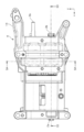
- FIG. 1 is an exploded perspective view of a balancer device 1 according to a first embodiment.
- 1 is a plan view of a balancer device 1 according to a first embodiment.
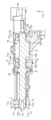
- FIG. 3 is a cross-sectional view taken along line S3-S3 in FIG.
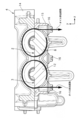
- FIG. 3 is a sectional view taken along line S4-S4 in FIG.
- FIG. 6 is a perspective view of a drive side balancer shaft 2 according to the first, third, and fifth embodiments.
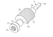
- FIG. 6 is a perspective view of a driven-side balancer shaft 3 according to the first, third, and fifth embodiments.
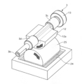
- 2 shows an example of a method for coating the oil repellent layer 23. It is a figure which shows the rotational resistance reduction effect of Embodiment 1.
- FIG. 1 is an exploded perspective view of a balancer device 1 according to a first embodiment.
- FIG. 3 is a cross-sectional view taken along line S3-S3 in FIG.
- FIG. 3 is a sectional view taken along
- FIG. 6 is a cross-sectional view in the x-axis direction of a drive-side balancer shaft 2 of Embodiment 4.
- FIG. 6 is a cross-sectional view in the x-axis direction of a driven-side balancer shaft 3 of Embodiment 4.
- FIG. 6 is an explanatory diagram of a method of shot peening the lower housing 15. It is an example of shot blasting.
- Embodiment 1 1 is an exploded perspective view of the balancer device 1 according to the first embodiment
- FIG. 2 is a plan view of the balancer device 1 according to the first embodiment
- FIG. 3 is a cross-sectional view taken along line S3-S3 in FIG. It is a sectional view taken along line S4-S4.
- the balancer device 1 of the first embodiment is accommodated in an oil pan (not shown) attached to the lower part of a cylinder block of an engine (internal combustion engine).
- the engine is, for example, an in-line four-cylinder reciprocating engine.
- the balancer device 1 includes a drive side balancer shaft 2, a driven side balancer shaft 3, and a housing 4.
- the driving side balancer shaft 2 and the driven side balancer shaft 3 are accommodated in the housing 4.
- the drive-side balancer shaft 2 and the driven-side balancer shaft 3 are arranged parallel to each other along the axial direction of the engine.
- the x-axis is set in the longitudinal direction of the engine
- the y-axis is set in the vertical direction
- the z-axis is set in the horizontal direction of the engine
- the direction from the engine rear side to the front side is the x axis positive direction
- the engine lower side is directed upward.
- the balancer device 1 according to the first embodiment will be described with the direction as the y-axis positive direction and the direction from the left side to the right side as viewed from the front side of the engine as the z-axis positive direction.
- the drive-side balancer shaft 2 has cylindrical journal portions 2c, 2d, and 2e at the x-axis positive direction end 2a, the x-axis direction center, and the x-axis negative direction end 2b.
- Each journal portion 2c, 2d, 2e is supported so as to be rotatable about the x-axis with respect to the housing 4 via sliding bearings 5, 6, 7.
- Each of the plain bearings 5, 6, and 7 is formed by being divided into two halves in the y-axis direction.
- Each plain bearing 5, 6, 7 has oil holes 5a, 6a, 7a at the center in the x-axis direction.
- the drive-side balancer shaft 2 has a drive-side balancer weight 8 between the second journal portion 2d and the third journal portion 2e in the x-axis direction.
- the drive side balancer weight 8 has a semi-cylindrical shape when viewed from the x-axis direction.
- a balancer drive gear 9 is fixed between the first journal portion 2c and the second journal portion 2d in the x-axis direction of the drive-side balancer shaft 2.
- the balancer drive gear 9 is a helical gear.
- a balancer sprocket (not shown) is fixed to the positive end 2a of the drive-side balancer shaft 2 in the x-axis direction. Rotational force from the engine crankshaft is transmitted to the balancer sprocket via a drive chain (not shown). Note that the ratio of the rotational speed of the crankshaft and the drive-side balancer shaft 2 is 1: 2.
- the axial length of the driven balancer shaft 3 is shorter than that of the drive side balancer shaft 2.
- the driven balancer shaft 3 has cylindrical journal portions 3c and 3d in the vicinity of the x-axis positive direction end 3a and the x-axis negative direction end 3b.
- a gear for rotationally driving an oil pump (not shown) is fixed to the x-axis negative direction end 3b.
- Each journal portion 3c, 3d is supported so as to be rotatable about the x axis with respect to the housing 4 via cylindrical sliding bearings 10, 11.
- Each of the plain bearings 10 and 11 is formed by being divided into two halves in the y-axis direction.
- Each of the plain bearings 10 and 11 has oil holes 10a and 11a at the center in the x-axis direction.
- the first journal portion 3c and the second journal portion 3d are provided at the same positions as the second journal portion 2d and the third journal portion 2e of the drive side balancer shaft 2 in the x-axis direction.
- the driven-side balancer shaft 3 includes a driven-side balancer weight 12 between the first journal portion 3c and the second journal portion 3d in the x-axis direction.
- the driven side balancer weight 12 has a semi-cylindrical shape when viewed from the x-axis direction.
- a balancer driven gear 13 is fixed to the x-axis positive direction end 3a of the driven side balancer shaft 3.
- the balancer driven gear 13 is a helical gear that meshes with the balancer drive gear 9.
- the balancer drive gear 9 and the balancer driven gear 13 have the same number of teeth.
- the housing 4 has an upper housing 14 and a lower housing 15. Both housings 14 and 15 are formed in a substantially half-divided shape that is vertically divided by a mating surface parallel to the x-axis. Both housings 14 and 15 are fastened to the lower part of the cylinder block by a plurality of bolts 16 so as to overlap each other.
- the upper housing 14 and the lower housing 15 are provided with bearing support portions 14a, 14b, 14c, 15a, 15b, 15c extending in the y-axis direction. Upper portions of the plain bearings 5, 6, 7, 10, and 11 are attached to the bearing support portions 14a, 14b, and 14c of the upper housing 14, respectively.
- Each bearing support portion 14a, 14b, 14c, 15a, 15b, 15c has oil grooves 17a, 17b, 17c, which are opposed to the outer peripheral sides of the sliding bearings 5, 6, 7, 10, 11 and extend in the z-axis direction. 17d, 17e, and 17f are formed. Oil pumped from an oil pump is supplied to each of the oil grooves 17a, 17b, 17c, 17d, 17e, and 17f.
- a gear housing chamber 18 is provided on the x-axis positive direction side of the bearing support portions 14b and 15b.
- a balancer driving gear 9 and a balancer driven gear 13 are accommodated in the gear accommodating chamber 18 so as to be rotatable around the x axis.
- the x axis positive direction side of the gear housing chamber 18 communicates with the outside of the housing 4.
- the lower part of the lower housing 15 is immersed in the oil in the oil pan, but the oil level in the oil pan is set to a height at which the oil does not flow into the gear housing chamber 18.
- a weight accommodating chamber (accommodating portion) 19 is provided inside the housing 4 and between the bearing support portions 14b and 15b and the bearing support portions 14c and 15c in the x-axis direction.
- a drive-side balancer weight 8 and a driven-side balancer weight 12 are stored so as to be rotatable about the x axis.
- discharge windows 20 and 21 that communicate the weight storage chamber 19 and the outside of the lower housing 15 are formed side by side in the x-axis direction on both sides in the z-axis direction of the weight storage chamber 19.
- FIG. 5 is a perspective view of the drive side balancer shaft 2 of the first embodiment
- FIG. 6 is a perspective view of the driven side balancer shaft 3 of the first embodiment.
- the driving-side balancer weight 8 and the driven-side balancer weight 12 have oil-repellent layers 22 and 23 in semicircular arc-shaped portions 8a and 12a as seen from the x-axis direction on the outer circumferential surface (direction around the x-axis). .
- the oil repellent layers 22 and 23 are for reducing the rotational resistance of the drive side balancer shaft 2 and the driven side balancer shaft 3, and are made of fluororesin such as polytetrafluoroethylene (PTFE) or tetrafluoroethylene-perfluoroalkyl vinyl ether.
- PTFE polytetrafluoroethylene
- the critical surface tension of the oil repellent layers 22 and 23 is less than 30 [mN / m], and the surface thereof has higher oil repellency than the material surfaces of the drive side balancer weight 8 and the driven side balancer weight 12.
- the fluororesin is colorless and transparent. As a result, the appearance of the drive-side balancer weight 8 and the driven-side balancer weight 12 is not impaired.
- the fluororesin may be colored with a color different from that of the outer peripheral surfaces 8a and 12a so that the presence or absence of the oil repellent layers 22 and 23 can be visually recognized.
- FIG. 7 shows an example of a coating method.
- the outer peripheral surface 12a of the driven side balancer weight 12 is brought into contact with the roller 25 whose lower part is immersed in the fluorine coating agent 24, and the driven side balancer shaft 3 is rotated in this state.
- the oil repellent layer 23 can be formed on the outer peripheral surface 12a.
- the oil repellent layer 23 is cured by heating the outer peripheral surface 12a to a predetermined temperature.
- the drive-side balancer shaft 2 rotates at twice the speed of the crankshaft via the balancer sprocket.
- the driven side balancer shaft 3 rotates at the same speed in the opposite direction to the driving side balancer shaft 2 through meshing rotation transmission between the balancer driving gear 9 and the balancer driven gear 13.
- the driving side balancer weight 8 and the driven side balancer weight 12 also rotate in the opposite directions to cancel the left and right centrifugal forces of the driving side balancer shaft 2 and the driven side balancer shaft 3 themselves.
- the driving-side balancer weight 8 and the driven-side balancer weight 12 rotate with the rotation of the driving-side balancer shaft 2 and the driven-side balancer shaft 3 to transmit the excitation force to the engine, thereby generating secondary vibration of the engine. Can be suppressed.
- the oil that has flowed into the weight storage chamber 19 of the housing 4 is scraped up by the drive-side balancer weight 8 and the driven-side balancer weight 12, and then on both sides of the housing 4 in the z-axis direction.
- the formed discharge windows 20 and 21 are discharged to the outside of the housing 4. The discharged oil is returned to the oil pan.
- the balancer device oil agitation (dragging) by the balancer weight causes rotational resistance of the balancer shaft, leading to deterioration in engine fuel efficiency.
- the balancer shaft is covered with the housing, inflow of oil into the weight accommodating chamber is inevitable. For example, a part of the oil supplied to the slide bearing flows into the weight storage chamber.
- the rotational resistance can be reduced by increasing the distance between the outer circumferential surface of the balancer weight and the inner circumferential surface of the weight storage chamber, the apparatus is increased in size.
- the driving side balancer weight 8 and the driven side balancer weight 12 have higher oil repellency on the outer peripheral surfaces 8a and 12a than the material surfaces of the driving side balancer weight 8 and the driven side balancer weight 12.
- Oil repellent layers 22 and 23 are provided.
- the oil sliding property droplet removal property
- the rotational resistance of the drive side balancer shaft 2 and the driven side balancer shaft 3 can be reduced without increasing the size of the balancer device 1.
- energy loss can be reduced as compared with the conventional balancer device, and deterioration of fuel consumption can be suppressed.
- the effect of reducing the rotational resistance of the first embodiment is particularly remarkable in a cryogenic environment where the oil viscosity is high.
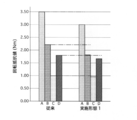
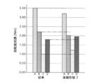
- FIG. 8 is a diagram showing the rotational resistance reduction effect of the first embodiment.
- the rotational resistance values of the drive-side balancer shaft 2 and the driven-side balancer shaft 3 for each mode are different between the conventional balancer device and the balancer device 1 of the first embodiment. It was obtained by experiment.
- A is an engine start mode, and the engine torque reaches the peak torque in the section from the engine stop state until the engine start is started with the cell motor and the engine speed changes from 0 [rpm] to 200 [rpm]. It is the rotation resistance value at the time.
- B is an engine start mode, which is an average value of rotational resistance values measured until 1.0 [sec] has elapsed since the start of the engine with the cell motor from the engine stop state.
- C is a fuel consumption evaluation mode, which is a rotational resistance value when the engine speed is 2,000 [rpm].
- D is a high-speed region mode, and is a rotational resistance value when the engine speed is 4,000 [rpm].
- the balancer device 1 of the first embodiment has a smaller rotational resistance value than the conventional balancer device in all modes. That is, by providing the oil-repellent layers 22 and 23 only on the outer peripheral surfaces 8a and 12a of the driving side balancer weight 8 and the driven side balancer weight 12, the rotational resistance can be reduced regardless of the state of the engine.
- the critical surface tension of the oil repellent layers 22 and 23 is less than 30 [mN / m]. In general, the critical surface tension of engine oil is 30 [mN / m] or more. Therefore, by making the critical surface tension of the oil repellent layers 22 and 23 smaller than the critical surface tension of the oil, the drive-side balancer weight 8 and Oil dragging by the driven balancer weight 12 can be effectively suppressed, and a remarkable rotational resistance reduction effect can be obtained. Since the oil repellent layers 22 and 23 of Embodiment 1 are made of a fluororesin, the oil repellent layers 22 and 23 can be easily formed. Moreover, since the fluororesin has higher oil repellency than other resins, the rotational resistance can be effectively reduced.
- the wear resistance and non-viscosity of the oil repellent layers 22 and 23 can be improved as compared with the case of using other fluororesins.
- PFA the fluororesin
- the non-adhesiveness, chemical resistance, and corrosion resistance in a high temperature environment of the oil repellent layers 22 and 23 can be improved as compared with the case of using PTFE.
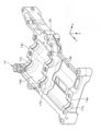
- FIG. 9 is a perspective view of the upper housing 14 of the second embodiment as viewed from the y-axis negative direction side
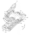
- FIG. 10 is a perspective view of the lower housing 15 of the second embodiment as viewed from the y-axis positive direction side.
- the upper housing 14 and the lower housing 15 have oil-repellent layers 26 and 27 on the inner peripheral surfaces 14d and 15d in the circumferential direction (direction around the x axis) of the weight accommodating chamber 19.
- the oil repellent layers 26 and 27 are the same as the oil repellent layers 22 and 23 of the first embodiment.
- the oil repellent layers 26 and 27 are formed by a cleaning process (first process), a coating process (second process), and a drying process.
- first process the inner peripheral surfaces 14d and 15d of the upper housing 14 and the lower housing 15 are cleaned.
- coating process fluorine coating (fluororesin) is applied to the inner peripheral surfaces 14d and 15d.
- the inner peripheral surfaces 14d and 15d are heated to a predetermined temperature to cure the oil repellent layers 26 and 27.
- FIG. 11 is a diagram showing the rotational resistance reduction effect of the second embodiment.
- the balancer device 1 of the second embodiment is suitable for an engine balancer device in an idle stop vehicle.
- the balancer device 1 of the third embodiment is different from the first and second embodiments in that both the outer circumferential surface of the balancer weight and the inner circumferential surface of the weight storage chamber have an oil repellent layer. Only the parts different from the first and second embodiments will be described below.
- FIG. 12 is a diagram showing the rotational resistance reduction effect of the third embodiment. Although the rotational resistance reduction effect cannot be obtained in the C and D modes, the rotational resistance value in the A and B modes is higher than that of the conventional balancer device. It is getting smaller. Therefore, the balancer device 1 of the third embodiment is suitable for an engine balancer device in an idle stop vehicle.
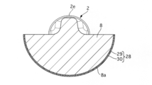
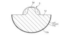
- the balancer device 1 of the fourth embodiment is different from the first embodiment in that the oil repellent layer has a two-layer structure. Only the parts different from the first embodiment will be described below. 13 is a cross-sectional view in the x-axis direction of the drive-side balancer shaft 2 of the fourth embodiment, and FIG. 14 is a cross-sectional view in the x-axis direction of the driven-side balancer shaft 3 of the fourth embodiment.
- the oil repellent layer 28 of the drive-side balancer weight 8 has a pretreatment film layer 29 and an oil repellent film layer 30.
- the undercoat film layer 29 is a layer that includes a paint that emits light in the visible light region when irradiated with ultraviolet rays, and is applied to the outer peripheral surface of the drive-side balancer weight 8.
- the oil repellent coating layer 30 is a layer applied to the outer peripheral surface of the pretreatment coating layer 29, and is formed using a fluororesin such as PTFE or PFA.
- the critical surface tension of the oil repellent coating layer 30 is less than 30 [mN / m], similar to the oil repellent layer 23 of the first embodiment.
- the oil repellent layer 31 of the driven side balancer weight 12 has a pretreatment coating layer 32 and an oil repellent coating layer 33, similar to the oil repellent layer 28.
- the lower treatment coating layer 32 and the oil repellent coating layer 33 are the same as the lower treatment coating layer 28 and the oil repellent coating layer 29.
- the drive-side balancer weight 8 and the driven-side balancer weight 12 are coated with the oil-repellent layers 28 and 31 by irradiating the drive-side balancer weight 8 and the driven-side balancer weight 12 with black light. It can be determined whether or not.
- the balancer device 1 of the fifth embodiment is different from the first embodiment in that the surface roughness of the inner circumferential surface of the weight storage chamber is rougher than the surface roughness of the oil repellent layer. Only the parts different from the first embodiment will be described below.
- the circumferential inner peripheral surfaces 14 d and 15 d of the weight accommodating chamber 19 are uneven, and the surface roughness thereof is determined by the driving-side balancer weight 8 and the driven-side balancer weight 12. It is rougher than the surface roughness of the material surface.
- the uneven shape is formed by performing shot blasting on the inner peripheral side of the upper housing 14 and the lower housing 15.
- the lower housing 15 is an explanatory view of a method of shot peening the lower housing 15 as an example of shot blasting.
- the lower housing 15 suspended from the hook 34 is rotated, and an infinite number of projectiles 36 (zinc balls) are collided from the projector 35 toward the lower housing 15 for a predetermined time.
- the concave and convex shapes can be formed on the circumferential inner peripheral surfaces 14d and 15d while deburring the upper housing 14 and the lower housing 15.
- the circumferential inner circumferential surfaces 14d and 15d have a surface roughness higher than that of the oil repellent layers 22 and 23 by making the circumferential inner circumferential surfaces 14d and 15d of the weight storage chamber 19 have an uneven shape.
- the circumferential inner peripheral surfaces 14d and 15d are oleophilic. For this reason, when the drive-side balancer shaft 2 and the driven-side balancer shaft 3 are driven to rotate, the oil that flows into the weight storage chamber 19 acts on the oil that flows into the weight storage chamber 19. The rotational resistance of the drive side balancer shaft 2 and the driven side balancer shaft 3 can be further reduced.
- the balancer device 1 of the sixth embodiment is different from the fifth embodiment in that the housing 4 is formed by casting. Only the parts different from the fifth embodiment will be described below.
- the upper housing 14 and the lower housing 15 of the sixth embodiment are formed by casting. This eliminates the need for a step for forming the uneven shape on the circumferential inner peripheral surfaces 14d and 15d, so that the uneven shape on the circumferential inner peripheral surfaces 14d and 15d can be easily compared to the case of the fifth embodiment. Can be formed.
- the balancer device 1 of the seventh embodiment is different from the first embodiment in that the oil repellent layer is machined.
- fine periodic structures are provided as the oil repellent layers 22 and 23 on the outer peripheral surfaces of the drive side balancer weight 8 and the driven side balancer weight 12.
- the fine periodic structure has oil repellency equivalent to that of the oil repellent layers 22 and 23 of the first embodiment.
- the fine periodic structure can be formed by cutting. Note that a fine periodic structure may be formed using a femtosecond laser. Thereby, a fine periodic structure can be formed in a shorter time than cutting.
- the oil repellent layers 22 and 23 are formed by machining, the disappearance of the oil repellent layers 22 and 23 due to heat or the like can be prevented.
- the oil repellent layer on the inner peripheral surface in the circumferential direction of the weight storage chamber may have a two-layer structure of a pretreatment film layer and an oil repellent film layer.
- the balancer device includes a balancer shaft that is rotationally driven by an internal combustion engine and has a balancer weight, and a housing that rotatably supports the balancer shaft and has a housing portion that houses the balancer weight.
- An oil repellent layer is provided on the outer circumferential surface of the balancer weight and / or the inner circumferential surface of the housing portion in the circumferential direction.
- the oil repellent layer is a resin.
- the resin is a fluororesin.
- the fluororesin is polytetrafluoroethylene (PTFE). In still another preferred embodiment, in any of the above embodiments, the fluororesin is a tetrafluoroethylene-perfluoroalkyl vinyl ether copolymer (PFA). In still another preferred embodiment, in any of the above embodiments, the resin is colorless and transparent. In still another preferred aspect, in any one of the above aspects, the resin is colored in a color different from a circumferential outer circumferential surface of the balancer shaft and / or a circumferential inner circumferential surface of the housing portion.
- the oil repellent layer includes a pretreatment coating layer containing a paint that emits light in a visible light region when irradiated with ultraviolet rays, and an oil repellent coating layer covering the subtreatment coating layer. And have.
- the oil repellent layer is provided only on the outer circumferential surface of the balancer weight in the circumferential direction.
- the oil repellent layer is formed by machining.
- the machining is a cutting process.
- the machining is laser processing.
- the circumferential inner circumferential surface of the housing portion is rougher than the circumferential outer circumferential surface of the balancer weight.
- the inner peripheral surface of the housing portion has an uneven shape.
- the housing is formed by casting.
- the uneven shape is formed by shot blasting.
- the shot blasting is shot peening in which zinc spheres are sprayed.
- the circumferential inner circumferential surface of the housing portion is oleophilic.
- the balancer device includes a housing that rotatably supports the balancer shaft and has a housing portion that houses the balancer weight, and a circumferential outer peripheral surface of the balancer weight and / or the housing. The critical surface tension of the inner circumferential surface of the part is less than 30 mN / m.
- a processing method of the balancer device includes a balancer shaft that is rotationally driven by an internal combustion engine and has a balancer weight, a housing that rotatably supports the balancer shaft and that houses the balancer weight.
- a first step of cleaning a circumferential outer peripheral surface of the balancer weight and / or a circumferential inner peripheral surface of the housing portion, and a circumferential outer peripheral surface of the balancer weight And / or a second step of applying a material having oil repellency to the inner circumferential surface in the circumferential direction of the housing portion.
- this invention is not limited to the above-mentioned Example, Various modifications are included.
- the above-described embodiments have been described in detail for easy understanding of the present invention, and are not necessarily limited to those having all the configurations described.
- a part of the configuration of one embodiment can be replaced with the configuration of another embodiment, and the configuration of another embodiment can be added to the configuration of one embodiment.
Landscapes
- Engineering & Computer Science (AREA)
- General Engineering & Computer Science (AREA)
- Physics & Mathematics (AREA)
- Acoustics & Sound (AREA)
- Aviation & Aerospace Engineering (AREA)
- Mechanical Engineering (AREA)
- Cylinder Crankcases Of Internal Combustion Engines (AREA)
Abstract
バランサシャフトの回転抵抗を低減できるバランサ装置およびバランサ装置の加工方法を提供する。 バランサ装置は、駆動側バランサウエイトおよび従動側バランサウエイトの周方向外周面に撥油層を有する。
Description
本発明は、バランサ装置およびバランサ装置の加工方法に関する。
一般的に、内燃機関の振動を抑制するバランサ装置が知られている(例えば特許文献1)。
バランサ装置では、バランサウエイトによるオイルの撹拌がバランサシャフトの回転抵抗となる。この回転抵抗が大きいほどエネルギー損失が増大し、内燃機関の燃費が悪化する。このため、バランサシャフトの回転抵抗を低減して欲しいとのニーズがある。
本発明の目的の一つは、バランサシャフトの回転抵抗を低減できるバランサ装置およびバランサ装置の加工方法を提供することにある。
本発明の目的の一つは、バランサシャフトの回転抵抗を低減できるバランサ装置およびバランサ装置の加工方法を提供することにある。
本発明の一実施形態におけるバランサ装置は、バランサウエイトの周方向外周面および/または収容部の内周面に撥油層を有する。
よって、本発明の一実施形態にあっては、バランサシャフトの回転抵抗を低減できる。
〔実施形態1〕
図1は実施形態1のバランサ装置1の分解斜視図、図2は実施形態1のバランサ装置1の平面図、図3は図2のS3-S3線矢視断面図、図4は図2のS4-S4線矢視断面図である。
実施形態1のバランサ装置1は、エンジン(内燃機関)のシリンダブロック下部に取り付けられた図外のオイルパン内に収容されている。エンジンは、例えば直列4気筒のレシプロエンジンである。バランサ装置1は、駆動側バランサシャフト2、従動側バランサシャフト3およびハウジング4を有する。駆動側バランサシャフト2および従動側バランサシャフト3は、ハウジング4内に収容されている。駆動側バランサシャフト2および従動側バランサシャフト3は、その軸方向をエンジン前後方向に沿って互いに平行に配置されている。以下、エンジンの前後方向にx軸、上下方向にy軸、エンジンの左右方向にz軸を設定し、エンジン後方側から前方側へ向かう方向をx軸正方向、エンジン下方側から上方側へ向かう方向をy軸正方向、エンジンの正面側から見て左側から右側へ向かう方向をz軸正方向として実施形態1のバランサ装置1を説明する。
駆動側バランサシャフト2は、x軸正方向端2a、x軸方向中央およびx軸負方向端2bに円柱状のジャーナル部2c,2d,2eを有する。各ジャーナル部2c,2d,2eは、滑り軸受5,6,7を介してハウジング4に対しx軸周り回転可能に支持されている。各滑り軸受5,6,7は、y軸方向に半割状に二分割して形成されている。各滑り軸受5,6,7は、x軸方向中央に油孔5a,6a,7aを有する。駆動側バランサシャフト2は、第2ジャーナル部2dと第3ジャーナル部2eとのx軸方向間に駆動側バランサウエイト8を有する。駆動側バランサウエイト8は、x軸方向から見て半円柱状である。駆動側バランサシャフト2のx軸方向において、第1ジャーナル部2cと第2ジャーナル部2dとの間には、バランサ駆動ギア9が固定されている。バランサ駆動ギア9はヘリカルギアである。駆動側バランサシャフト2のx軸正方向端2aには、図外のバランサスプロケットが固定されている。バランサスプロケットには、図外の駆動チェーンを介してエンジンのクランクシャフトからの回転力が伝達される。なお、クランクシャフトと駆動側バランサシャフト2の回転速度の比は1:2とする。
従動側バランサシャフト3は、その軸長が駆動側バランサシャフト2よりも短く形成されている。従動側バランサシャフト3は、x軸正方向端3a付近およびx軸負方向端3b付近に、円柱状のジャーナル部3c,3dを有する。x軸負方向端3bには、図外のオイルポンプを回転駆動するためのギアが固定される。各ジャーナル部3c,3dは、円筒状の滑り軸受10,11を介してハウジング4に対しx軸周り回転可能に支持されている。各滑り軸受10,11は、y軸方向に半割状に二分割して形成されている。各滑り軸受10,11は、x軸方向中央に油孔10a,11aを有する。第1ジャーナル部3cおよび第2ジャーナル部3dは、x軸方向において駆動側バランサシャフト2の第2ジャーナル部2dおよび第3ジャーナル部2eと同じ位置に設けられている。従動側バランサシャフト3は、第1ジャーナル部3cと第2ジャーナル部3dとのx軸方向間に従動側バランサウエイト12を有する。従動側バランサウエイト12は、x軸方向から見て半円柱状である。従動側バランサシャフト3のx軸正方向端3aには、バランサ従動ギア13が固定されている。バランサ従動ギア13は、バランサ駆動ギア9と噛み合うヘリカルギアである。バランサ駆動ギア9とバランサ従動ギア13の歯数は同じである。
ハウジング4は、アッパハウジング14およびロアハウジング15を有する。両ハウジング14,15は、x軸と平行な合わせ面で上下に二分された略半割状に形成されている。両ハウジング14,15は、複数のボルト16により、上下に重なる状態でシリンダブロック下部に締結されている。アッパハウジング14およびロアハウジング15には、y軸方向に延びる軸受支持部14a,14b,14c,15a,15b,15cが設けられている。アッパハウジング14の各軸受支持部14a,14b,14cには、各滑り軸受5,6,7,10,11の上側部分が取り付けられる。ロアハウジング15の各軸受支持部15a,15b,15cには、各滑り軸受5,6,7,10,11の下側部分が取り付けられる。各軸受支持部14a,14b,14c,15a,15b,15cには、各滑り軸受5,6,7,10,11の外周側と対向し、z軸方向に延びる油溝17a,17b,17c,17d,17e,17fが形成されている。各油溝17a,17b,17c,17d,17e,17fにはオイルポンプから圧送されたオイルが供給される。軸受支持部14b,15bのx軸正方向側には、ギア収容室18が設けられている。ギア収容室18には、バランサ駆動ギア9およびバランサ従動ギア13がx軸周り回転可能に収容されている。ロアハウジング15において、ギア収容室18のx軸正方向側はハウジング4の外部と連通している。なお、エンジン動作時、ロアハウジング15の下部はオイルパン内のオイルに浸かるものの、オイルパン内の油面は、ギア収容室18にオイルが流入しない高さに設定されている。ハウジング4の内部であって、軸受支持部14b,15bと軸受支持部14c,15cとのx軸方向間には、ウエイト収容室(収容部)19が設けられている。ウエイト収容室19には、駆動側バランサウエイト8および従動側バランサウエイト12がx軸周り回転可能に収容されている。ロアハウジング15において、ウエイト収容室19のz軸方向両側には、ウエイト収容室19とロアハウジング15の外部とを連通する排出窓20,21がx軸方向に並んで形成されている。
図5は実施形態1の駆動側バランサシャフト2の斜視図、図6は実施形態1の従動側バランサシャフト3の斜視図である。
駆動側バランサウエイト8および従動側バランサウエイト12は、その周方向(x軸周りの方向)外周面のうち、x軸方向から見て半円弧状の部分8a,12aに撥油層22,23を有する。撥油層22,23は、駆動側バランサシャフト2および従動側バランサシャフト3の回転抵抗を低減するためのもので、フッ素樹脂、例えばポリテトラフルオロエチレン(PTFE)またはテトラフルオロエチレン-パーフルオロアルキルビニルエーテル共重合体(PFA)を用いて形成されている。撥油層22,23の臨界表面張力は30[mN/m]未満であり、その表面は駆動側バランサウエイト8および従動側バランサウエイト12の素材表面よりも撥油性が高い。ここで、フッ素樹脂は無色透明とする。これにより、駆動側バランサウエイト8および従動側バランサウエイト12の外観を損なうことがない。なお、フッ素樹脂を外周面8a,12aとは異なる色で着色し、撥油層22,23の有無を視認可能としてもよい。
駆動側バランサウエイト8および従動側バランサウエイト12は、その周方向(x軸周りの方向)外周面のうち、x軸方向から見て半円弧状の部分8a,12aに撥油層22,23を有する。撥油層22,23は、駆動側バランサシャフト2および従動側バランサシャフト3の回転抵抗を低減するためのもので、フッ素樹脂、例えばポリテトラフルオロエチレン(PTFE)またはテトラフルオロエチレン-パーフルオロアルキルビニルエーテル共重合体(PFA)を用いて形成されている。撥油層22,23の臨界表面張力は30[mN/m]未満であり、その表面は駆動側バランサウエイト8および従動側バランサウエイト12の素材表面よりも撥油性が高い。ここで、フッ素樹脂は無色透明とする。これにより、駆動側バランサウエイト8および従動側バランサウエイト12の外観を損なうことがない。なお、フッ素樹脂を外周面8a,12aとは異なる色で着色し、撥油層22,23の有無を視認可能としてもよい。
次に、駆動側バランサシャフト2および従動側バランサシャフト3の製造方法を説明する。なお、両シャフト2,3は同一の製造工程で製造されるため、従動側バランサシャフト3の製造方法のみを説明し、駆動側バランサシャフト2の製造方法については省略する。
従動側バランサシャフト3は、加工工程、洗浄工程(第1工程)、コーティング工程(第2工程)および乾燥工程により製造される。加工工程では、切削加工により、素材に各ジャーナル部3c,3dおよび従動側バランサウエイト12を形成する。洗浄工程では、従動側バランサウエイト12の外周面12aを洗浄する。コーティング工程では、外周面12aにフッ素コーティング剤(フッ素樹脂)を塗布する。図7はコーティング方法の一例である。下部をフッ素コーティング剤24に浸したローラ25に、従動側バランサウエイト12の外周面12aを接触させ、この状態で従動側バランサシャフト3を回転させる。これにより、外周面12aに撥油層23を形成できる。乾燥工程では、外周面12aを所定温度まで加温して撥油層23を硬化させる。
従動側バランサシャフト3は、加工工程、洗浄工程(第1工程)、コーティング工程(第2工程)および乾燥工程により製造される。加工工程では、切削加工により、素材に各ジャーナル部3c,3dおよび従動側バランサウエイト12を形成する。洗浄工程では、従動側バランサウエイト12の外周面12aを洗浄する。コーティング工程では、外周面12aにフッ素コーティング剤(フッ素樹脂)を塗布する。図7はコーティング方法の一例である。下部をフッ素コーティング剤24に浸したローラ25に、従動側バランサウエイト12の外周面12aを接触させ、この状態で従動側バランサシャフト3を回転させる。これにより、外周面12aに撥油層23を形成できる。乾燥工程では、外周面12aを所定温度まで加温して撥油層23を硬化させる。
実施形態1のバランサ装置1は、エンジンが始動されてクランクシャフトが回転駆動すると、バランサスプロケットを介して駆動側バランサシャフト2がクランクシャフトの2倍の速度で回転する。従動側バランサシャフト3はバランサ駆動ギア9とバランサ従動ギア13の噛み合い回転伝達を経て駆動側バランサシャフト2と反対方向へ同速度で回転する。これにより、駆動側バランサウエイト8および従動側バランサウエイト12も互いに反対方向へ回転しながら駆動側バランサシャフト2および従動側バランサシャフト3自身の左右の遠心力をキャンセルする。このように、駆動側バランサシャフト2および従動側バランサシャフト3の回転に伴い駆動側バランサウエイト8および従動側バランサウエイト12が回転して起振力をエンジンに伝達することにより、エンジンの二次振動を抑制できる。このとき、ハウジング4のウエイト収容室19内に流入したオイルは、図4に示すように、駆動側バランサウエイト8および従動側バランサウエイト12により掻き上げられた後、ハウジング4のz軸方向両側に形成された排出窓20,21からハウジング4の外部へ排出される。排出されたオイルは、オイルパンへ戻される。
バランサ装置において、バランサウエイトによるオイルの撹拌(引き摺り)はバランサシャフトの回転抵抗となるため、エンジンの燃費悪化を招く。バランサシャフトはハウジングで覆われているものの、ウエイト収容室内へのオイルの流入は避けられない。例えば、滑り軸受に供給されたオイルの一部はウエイト収容室に流入する。なお、バランサウエイトの周方向外周面およびウエイト収容室の内周面間の距離を大きくとることで回転抵抗は軽減できるものの、装置の大型化を伴う。これに対し、実施形態1では、駆動側バランサウエイト8および従動側バランサウエイト12は、その外周面8a,12aに、駆動側バランサウエイト8および従動側バランサウエイト12の素材表面よりも撥油性の高い撥油層22,23を有する。これにより、撥油層22,23を持たない従来のバランサウエイトに対してオイルの滑落性(液滴除去性)を高められる。このため、バランサ装置1の大型化を伴うことなく、駆動側バランサシャフト2および従動側バランサシャフト3の回転抵抗を低減できる。この結果、従来のバランサ装置よりもエネルギー損失を低減でき、燃費の悪化を抑制できる。実施形態1の回転抵抗低減効果は、オイル粘度が高くなる極低温環境下において特に顕著となる。
図8は、実施形態1の回転抵抗低減効果を示す図であり、モード別に駆動側バランサシャフト2および従動側バランサシャフト3の回転抵抗値を従来のバランサ装置と実施形態1のバランサ装置1でそれぞれ実験により求めたものである。なお、Aはエンジン始動モードであり、エンジン停止状態からセルモータでエンジン始動を開始し、エンジン回転数が0[rpm]から200[rpm]に変化するまでの区間において、エンジントルクがピークトルクを迎えたときの回転抵抗値である。Bはエンジン始動モードであり、エンジン停止状態からセルモータでエンジン始動を開始してから1.0[sec]が経過するまでに計測した回転抵抗値の平均値である。Cは燃費評価モードであり、エンジン回転数が2,000[rpm]のときの回転抵抗値である。Dは高速域モードであり、エンジン回転数が4,000[rpm]のときの回転抵抗値である。図8に示すように、実施形態1のバランサ装置1では、全てのモードにおいて従来のバランサ装置よりも回転抵抗値が小さい。つまり、撥油層22,23を駆動側バランサウエイト8および従動側バランサウエイト12の外周面8a,12aのみに設けたことにより、エンジンの状態にかかわらず回転抵抗を低減できる。
実施形態1では、撥油層22,23の臨界表面張力を30[mN/m]未満とした。一般的に、エンジンオイルの臨界表面張力は30[mN/m]以上であるから、撥油層22,23の臨界表面張力をオイルの臨界表面張力よりも小さくすることにより、駆動側バランサウエイト8および従動側バランサウエイト12によるオイルの引き摺りを効果的に抑制でき、顕著な回転抵抗低減効果が得られる。
実施形態1の撥油層22,23はフッ素樹脂であるから、撥油層22,23の形成が容易である。また、フッ素樹脂は他の樹脂と比べて撥油性が高いため、回転抵抗を効果的に低減できる。そして、フッ素樹脂としてPTFEを用いることにより、他のフッ素樹脂を用いた場合と比較して、撥油層22,23の耐摩耗性および非粘性を向上できる。なお、フッ素樹脂としてPFAを用いることにより、PTFEを用いた場合と比較して、撥油層22,23の非粘着性、耐薬品性および高温環境下における耐食性を向上できる。
実施形態1の撥油層22,23はフッ素樹脂であるから、撥油層22,23の形成が容易である。また、フッ素樹脂は他の樹脂と比べて撥油性が高いため、回転抵抗を効果的に低減できる。そして、フッ素樹脂としてPTFEを用いることにより、他のフッ素樹脂を用いた場合と比較して、撥油層22,23の耐摩耗性および非粘性を向上できる。なお、フッ素樹脂としてPFAを用いることにより、PTFEを用いた場合と比較して、撥油層22,23の非粘着性、耐薬品性および高温環境下における耐食性を向上できる。
〔実施形態2〕
実施形態2のバランサ装置1は、バランサウエイトの周方向外周面が撥油層を有さず、ウエイト収容室の内周面が撥油層を有する点で実施形態1と相違する。以下、実施形態1と異なる部分のみ説明する。
図9は実施形態2のアッパハウジング14をy軸負方向側から見た斜視図、図10は実施形態2のロアハウジング15をy軸正方向側から見た斜視図である。
アッパハウジング14およびロアハウジング15は、ウエイト収容室19の周方向(x軸周りの方向)内周面14d,15dに撥油層26,27を有する。撥油層26,27は、実施形態1の撥油層22,23と同様のものとする。
撥油層26,27は、洗浄工程(第1工程)、コーティング工程(第2工程)および乾燥工程により形成される。洗浄工程では、アッパハウジング14およびロアハウジング15において、内周面14d,15dをそれぞれ洗浄する。コーティング工程では、内周面14d,15dにフッ素コーティング(フッ素樹脂)をそれぞれ塗布する。乾燥工程では、内周面14d,15dを所定温度まで加温して撥油層26,27を硬化させる。
図11は、実施形態2の回転抵抗低減効果を示す図であり、A、C、Dの各モードでは回転抵抗低減効果が得られないものの、Bのモードでは従来のバランサ装置よりも回転抵抗値が小さくなっている。したがって、頻繁にエンジンの停止と再始動を繰り返すアイドルストップ車両では、エンジン再始動時における駆動側バランサシャフト2および従動側バランサシャフト3の回転抵抗低減効果により、燃費悪化の抑制に貢献できる。よって、実施形態2のバランサ装置1は、アイドルストップ車両におけるエンジンのバランサ装置に好適である。
〔実施形態3〕
実施形態3のバランサ装置1は、バランサウエイトの周方向外周面およびウエイト収容室の内周面が共に撥油層を有する点で実施形態1,2と相違する。以下、実施形態1,2と異なる部分のみ説明する。
実施形態3では、図5,6に示した実施形態1の駆動側バランサシャフト2および従動側バランサシャフト3と、図9,10に示した実施形態2のアッパハウジング14およびロアハウジング15を採用している。
図12は、実施形態3の回転抵抗低減効果を示す図であり、C、Dのモードでは回転抵抗低減効果が得られないものの、A、Bのモードでは従来のバランサ装置よりも回転抵抗値が小さくなっている。よって、実施形態3のバランサ装置1は、アイドルストップ車両におけるエンジンのバランサ装置に好適である。
〔実施形態4〕
実施形態4のバランサ装置1は、撥油層が2層構造である点で実施形態1と相違する。以下、実施形態1と異なる部分のみ説明する。
図13は実施形態4の駆動側バランサシャフト2のx軸方向断面図、図14は実施形態4の従動側バランサシャフト3のx軸方向断面図である。
実施形態4において、駆動側バランサウエイト8の撥油層28は、下処理被膜層29および撥油被膜層30を有する。下処理被膜層29は、紫外線を照射すると可視光領域の光を発する塗料を含む層であり、駆動側バランサウエイト8の外周面に塗布されている。撥油被膜層30は、下処理被膜層29の外周面に塗布された層であり、フッ素樹脂、例えばPTFEまたはPFAを用いて形成されている。撥油被膜層30の臨界表面張力は、実施形態1の撥油層23と同様、30[mN/m]未満である。従動側バランサウエイト12の撥油層31は、撥油層28と同様、下処理被膜層32および撥油被膜層33を有する。下処理被膜層32および撥油被膜層33は、下処理被膜層28および撥油被膜層29と同様である。
実施形態4のバランサ装置1では、駆動側バランサウエイト8および従動側バランサウエイト12にブラックライトを照射することにより、駆動側バランサウエイト8および従動側バランサウエイト12に撥油層28,31が塗布されているか否かを判別できる。
〔実施形態5〕
実施形態5のバランサ装置1は、ウエイト収容室の周方向内周面の表面粗さが、撥油層の表面粗さよりも粗い点で実施形態1と相違する。以下、実施形態1と異なる部分のみ説明する。
実施形態5では、アッパハウジング14およびロアハウジング15において、ウエイト収容室19の周方向内周面14d,15dを凹凸形状とし、その表面粗さを、駆動側バランサウエイト8および従動側バランサウエイト12の素材表面の表面粗さよりも粗くしている。凹凸形状は、アッパハウジング14およびロアハウジング15の内周側にショットブラスト加工を施すことにより形成されている。図15は、ショットブラスト加工の一例として、ロアハウジング15をショットピーニング加工する方法の説明図である。フック34にぶら下げたロアハウジング15を回転させ、ロアハウジング15に向かって投射機35から無数の投射物36(亜鉛球)を所定時間衝突させる。なお、アッパハウジング14についても同様である。これにより、アッパハウジング14およびロアハウジング15のバリ取りを行いつつ、周方向内周面14d,15dに凹凸形状を形成できる。
実施形態5では、ウエイト収容室19の周方向内周面14d,15dを凹凸形状とすることにより、周方向内周面14d,15dは、撥油層22,23よりも高い表面粗さを有する。換言すると、周方向内周面14d,15dは、親油性である。このため、駆動側バランサシャフト2および従動側バランサシャフト3の回転駆動時、ウエイト収容室19に流入したオイルには、当該オイルを留まらせようとする力が働くため、実施形態1と比較して、駆動側バランサシャフト2および従動側バランサシャフト3の回転抵抗をより低減できる。
〔実施形態6〕
実施形態6のバランサ装置1は、ハウジング4が鋳造により形成されている点で実施形態5と相違する。以下、実施形態5と異なる部分のみ説明する。
実施形態6のアッパハウジング14およびロアハウジング15は、鋳造により形成されている。これにより、周方向内周面14d,15dに凹凸形状を形成するための工程が不要となるから、実施形態5の場合と比較して、周方向内周面14d,15dの凹凸形状を容易に形成できる。
実施形態6のバランサ装置1は、ハウジング4が鋳造により形成されている点で実施形態5と相違する。以下、実施形態5と異なる部分のみ説明する。
実施形態6のアッパハウジング14およびロアハウジング15は、鋳造により形成されている。これにより、周方向内周面14d,15dに凹凸形状を形成するための工程が不要となるから、実施形態5の場合と比較して、周方向内周面14d,15dの凹凸形状を容易に形成できる。
〔実施形態7〕
実施形態7のバランサ装置1は、撥油層を機械加工した点で実施形態1と相違する。
実施形態7では、駆動側バランサウエイト8および従動側バランサウエイト12の外周面に、撥油層22,23として微細周期構造が施さている。微細周期構造は、実施形態1の撥油層22,23と同等の撥油性を有する。微細周期構造は、切削加工により形成可能である。なお、フェムト秒レーザを用いて微細周期構造を形成してもよい。これにより、切削加工よりも短時間で微細周期構造を形成できる。
実施形態7では、撥油層22,23が機械加工により形成されているため、熱等による撥油層22,23の消失を防止できる。
実施形態7のバランサ装置1は、撥油層を機械加工した点で実施形態1と相違する。
実施形態7では、駆動側バランサウエイト8および従動側バランサウエイト12の外周面に、撥油層22,23として微細周期構造が施さている。微細周期構造は、実施形態1の撥油層22,23と同等の撥油性を有する。微細周期構造は、切削加工により形成可能である。なお、フェムト秒レーザを用いて微細周期構造を形成してもよい。これにより、切削加工よりも短時間で微細周期構造を形成できる。
実施形態7では、撥油層22,23が機械加工により形成されているため、熱等による撥油層22,23の消失を防止できる。
〔他の実施形態〕
以上、本発明を実施するための実施形態を説明したが、本発明の具体的な構成は実施形態の構成に限定されるものではなく、発明の要旨を逸脱しない範囲の設計変更等があっても本発明に含まれる。
例えば、ウエイト収容室の周方向内周面の撥油層を、下処理被膜層および撥油被膜層の2層構造としてもよい。
以上、本発明を実施するための実施形態を説明したが、本発明の具体的な構成は実施形態の構成に限定されるものではなく、発明の要旨を逸脱しない範囲の設計変更等があっても本発明に含まれる。
例えば、ウエイト収容室の周方向内周面の撥油層を、下処理被膜層および撥油被膜層の2層構造としてもよい。
以上説明した実施形態から把握し得る技術的思想について、以下に記載する。
バランサ装置は、その一つの態様において、内燃機関によって回転駆動され、バランサウエイトを有するバランサシャフトと、前記バランサシャフトを回転可能に支持し、前記バランサウエイトを収容する収容部を有するハウジングと、を備え、前記バランサウエイトの周方向外周面および/または前記収容部の周方向内周面に撥油層を有する。
より好ましい態様では、上記態様において、前記撥油層は、樹脂である。
別の好ましい態様では、上記態様のいずれかにおいて、前記樹脂は、フッ素樹脂である。
さらに別の好ましい態様では、上記態様のいずれかにおいて、前記フッ素樹脂は、ポリテトラフルオロエチレン(PTFE)である。
さらに別の好ましい態様では、上記態様のいずれかにおいて、前記フッ素樹脂は、テトラフルオロエチレン-パーフルオロアルキルビニルエーテル共重合体(PFA)である。
さらに別の好ましい態様では、上記態様のいずれかにおいて、前記樹脂は、無色透明である。
さらに別の好ましい態様では、上記態様のいずれかにおいて、前記樹脂は、前記バランサシャフトの周方向外周面および/または前記収容部の周方向内周面とは異なる色で着色されている。
さらに別の好ましい態様では、上記態様のいずれかにおいて、前記撥油層は、紫外線を照射すると可視光領域の光を発する塗料を含む下処理被膜層と、前記下処理被膜層を覆う撥油被膜層とを有する。
さらに別の好ましい態様では、上記態様のいずれかにおいて、前記撥油層は、前記バランサウエイトの周方向外周面のみに設けられている。
さらに別の好ましい態様では、上記態様のいずれかにおいて、前記撥油層は、機械加工により形成されている。
さらに別の好ましい態様では、上記態様のいずれかにおいて、前記機械加工は、切削加工である。
さらに別の好ましい態様では、上記態様のいずれかにおいて、前記機械加工は、レーザ加工である。
さらに別の好ましい態様では、上記態様のいずれかにおいて、前記収容部の周方向内周面は、前記バランサウエイトの周方向外周面よりも表面粗さが粗い。
さらに別の好ましい態様では、上記態様のいずれかにおいて、前記収容部の内周面は、凹凸形状である。
さらに別の好ましい態様では、上記態様のいずれかにおいて、前記ハウジングは鋳造で形成されている。
さらに別の好ましい態様では、上記態様のいずれかにおいて、前記凹凸形状は、ショットブラストにより形成されている。
さらに別の好ましい態様では、上記態様のいずれかにおいて、前記ショットブラストは、亜鉛球を吹き付けるショットピーニングである。
さらに別の好ましい態様では、上記態様のいずれかにおいて、前記収容部の周方向内周面は、親油性である。
また、他の観点から、バランサ装置は、前記バランサシャフトを回転可能に支持し、前記バランサウエイトを収容する収容部を有するハウジングと、を備え、前記バランサウエイトの周方向外周面および/または前記収容部の周方向内周面の臨界表面張力が30mN/m未満である。
さらに、他の観点から、バランサ装置の加工方法は、内燃機関によって回転駆動され、バランサウエイトを有するバランサシャフトと、前記バランサシャフトを回転可能に支持し、前記バランサウエイトを収容する収容部を有するハウジングと、を備えたバランサ装置の加工方法であって、前記バランサウエイトの周方向外周面および/または前記収容部の周方向内周面を洗浄する第1工程と、前記バランサウエイトの周方向外周面および/または前記収容部の周方向内周面に撥油性を有する材料を塗布する第2工程と、を有する。
尚、本発明は上記した実施例に限定されるものではなく、様々な変形例が含まれる。例えば、上記した実施例は本発明を分かりやすく説明するために詳細に説明したものであり、必ずしも説明した全ての構成を備えるものに限定されるものではない。また、ある実施例の構成の一部を他の実施例の構成に置き換えることが可能であり、また、ある実施例の構成に他の実施例の構成を加えることも可能である。また、各実施例の構成の一部について、他の構成の追加・削除・置換をすることが可能である。
本願は、2016年9月23日付出願の日本国特許出願第2016-185104号に基づく優先権を主張する。2016年9月23日付出願の日本国特許出願第2016-185104号の明細書、特許請求の範囲、図面、及び要約書を含む全開示内容は、参照により本願に全体として組み込まれる。
1 バランサ装置2 駆動側バランサシャフト(バランサシャフト)3 従動側バランサシャフト(バランサシャフト)4 ハウジング8 駆動側バランサウエイト(バランサウエイト)8a 周方向外周面12 従動側バランサウエイト(バランサウエイト)12a 周方向外周面14 アッパハウジング14d 周方向内周面15 ロアハウジング15d 周方向内周面19 ウエイト収容室(収容部)22 撥油層23 撥油層26 撥油層27 撥油層28 撥油層29 下処理被膜層30 撥油被膜層31 撥油層32 下処理被膜層33 撥油被膜層
Claims (20)
- バランサ装置であって、該バランサ装置は、
内燃機関によって回転駆動され、バランサウエイトを有するバランサシャフトと、
前記バランサシャフトを回転可能に支持し、前記バランサウエイトを収容する収容部を有するハウジングと、
を備え、
前記バランサウエイトの周方向外周面および/または前記収容部の周方向内周面に撥油層を有するバランサ装置。 - 請求項1に記載のバランサ装置において、
前記撥油層は、樹脂であるバランサ装置。 - 請求項2に記載のバランサ装置において、
前記樹脂は、フッ素樹脂であるバランサ装置。 - 請求項3に記載のバランサ装置において、
前記フッ素樹脂は、ポリテトラフルオロエチレン(PTFE)であるバランサ装置。 - 請求項3に記載のバランサ装置において、
前記フッ素樹脂は、テトラフルオロエチレン-パーフルオロアルキルビニルエーテル共重合体(PFA)であるバランサ装置。 - 請求項2に記載のバランサ装置において、
前記樹脂は、無色透明であるバランサ装置。 - 請求項2に記載のバランサ装置において、
前記樹脂は、前記バランサシャフトの周方向外周面および/または前記収容部の周方向内周面とは異なる色で着色されているバランサ装置。 - 請求項1に記載のバランサ装置において、
前記撥油層は、紫外線を照射すると可視光領域の光を発する塗料を含む下処理被膜層と、前記下処理被膜層を覆う撥油被膜層とを有するバランサ装置。 - 請求項1に記載のバランサ装置において、
前記撥油層は、前記バランサウエイトの周方向外周面のみに設けられたバランサ装置。 - 請求項1に記載のバランサ装置において、
前記撥油層は、機械加工により形成された微細周期構造を有するバランサ装置。 - 請求項10に記載のバランサ装置において、
前記機械加工は、切削加工であるバランサ装置。 - 請求項10に記載のバランサ装置において、
前記機械加工は、レーザ加工であるバランサ装置。 - 請求項1に記載のバランサ装置において、
前記収容部の周方向内周面は、前記バランサウエイトの周方向外周面よりも表面粗さが粗いバランサ装置。 - 請求項13に記載のバランサ装置において、
前記収容部の内周面は、凹凸形状であるバランサ装置。 - 請求項14に記載のバランサ装置において、
前記ハウジングは鋳造で形成されたバランサ装置。 - 請求項14に記載のバランサ装置において、
前記凹凸形状は、ショットブラストにより形成されたバランサ装置。 - 請求項16に記載のバランサ装置において、
前記ショットブラストは、亜鉛球を吹き付けるショットピーニングであるバランサ装置。 - 請求項13に記載のバランサ装置において、
前記収容部の周方向内周面は、親油性であるバランサ装置。 - バランサ装置であって、該バランサ装置は、
内燃機関によって回転駆動され、バランサウエイトを有するバランサシャフトと、
前記バランサシャフトを回転可能に支持し、前記バランサウエイトを収容する収容部を有するハウジングと、
を備え、
前記バランサウエイトの周方向外周面および/または前記収容部の周方向内周面の臨界表面張力が30mN/m未満であるバランサ装置。 - バランサ装置の加工方法であって、
前記バランサ装置は、
内燃機関によって回転駆動され、バランサウエイトを有するバランサシャフトと、
前記バランサシャフトを回転可能に支持し、前記バランサウエイトを収容する収容部を有するハウジングと、
を備えており、
前記加工方法は、
前記バランサウエイトの周方向外周面および/または前記収容部の周方向内周面を洗浄する第1工程と、
前記バランサウエイトの周方向外周面および/または前記収容部の周方向内周面に撥油性を有する材料を塗布する第2工程と、
を有するバランサ装置の加工方法。
Applications Claiming Priority (2)
| Application Number | Priority Date | Filing Date | Title |
|---|---|---|---|
| JP2016-185104 | 2016-09-23 | ||
| JP2016185104A JP2018048706A (ja) | 2016-09-23 | 2016-09-23 | バランサ装置およびバランサ装置の加工方法 |
Publications (1)
| Publication Number | Publication Date |
|---|---|
| WO2018056017A1 true WO2018056017A1 (ja) | 2018-03-29 |
Family
ID=61690287
Family Applications (1)
| Application Number | Title | Priority Date | Filing Date |
|---|---|---|---|
| PCT/JP2017/031342 Ceased WO2018056017A1 (ja) | 2016-09-23 | 2017-08-31 | バランサ装置およびバランサ装置の加工方法 |
Country Status (2)
| Country | Link |
|---|---|
| JP (1) | JP2018048706A (ja) |
| WO (1) | WO2018056017A1 (ja) |
Citations (7)
| Publication number | Priority date | Publication date | Assignee | Title |
|---|---|---|---|---|
| JPS624653U (ja) * | 1985-06-24 | 1987-01-12 | ||
| JP2001247736A (ja) * | 2000-03-02 | 2001-09-11 | Daikin Ind Ltd | フッ素樹脂組成物 |
| FR2823279A1 (fr) * | 2001-04-09 | 2002-10-11 | Renault Sas | Arbre d'equilibrage comportant des blocs d'equilibrage cylindriques realises par surmoulage |
| JP2009079673A (ja) * | 2007-09-26 | 2009-04-16 | Toyoda Gosei Co Ltd | バランサ装置 |
| JP2011163360A (ja) * | 2010-02-04 | 2011-08-25 | Toyota Motor Corp | バランスシャフトのすべり支持構造 |
| US20150148272A1 (en) * | 2013-11-22 | 2015-05-28 | Imperial Innovations Limited | Gear and engine oils with reduced surface tension |
| JP2015174927A (ja) * | 2014-03-17 | 2015-10-05 | 三福工業株式会社 | 発泡体及びその製造方法 |
-
2016
- 2016-09-23 JP JP2016185104A patent/JP2018048706A/ja active Pending
-
2017
- 2017-08-31 WO PCT/JP2017/031342 patent/WO2018056017A1/ja not_active Ceased
Patent Citations (7)
| Publication number | Priority date | Publication date | Assignee | Title |
|---|---|---|---|---|
| JPS624653U (ja) * | 1985-06-24 | 1987-01-12 | ||
| JP2001247736A (ja) * | 2000-03-02 | 2001-09-11 | Daikin Ind Ltd | フッ素樹脂組成物 |
| FR2823279A1 (fr) * | 2001-04-09 | 2002-10-11 | Renault Sas | Arbre d'equilibrage comportant des blocs d'equilibrage cylindriques realises par surmoulage |
| JP2009079673A (ja) * | 2007-09-26 | 2009-04-16 | Toyoda Gosei Co Ltd | バランサ装置 |
| JP2011163360A (ja) * | 2010-02-04 | 2011-08-25 | Toyota Motor Corp | バランスシャフトのすべり支持構造 |
| US20150148272A1 (en) * | 2013-11-22 | 2015-05-28 | Imperial Innovations Limited | Gear and engine oils with reduced surface tension |
| JP2015174927A (ja) * | 2014-03-17 | 2015-10-05 | 三福工業株式会社 | 発泡体及びその製造方法 |
Also Published As
| Publication number | Publication date |
|---|---|
| JP2018048706A (ja) | 2018-03-29 |
Similar Documents
| Publication | Publication Date | Title |
|---|---|---|
| JP5697344B2 (ja) | 差動装置 | |
| JP5699058B2 (ja) | 水冷エンジン | |
| JP2009127842A (ja) | 歯車 | |
| JP2012162974A (ja) | 合成励振ギヤを有する振動ローラ及びその操作方法 | |
| EP3116733B1 (en) | Vehicle drive apparatus | |
| WO2014119024A1 (ja) | 車両用駆動装置 | |
| JP2018048706A (ja) | バランサ装置およびバランサ装置の加工方法 | |
| JP2014051957A (ja) | 水圧回転機 | |
| JP6395157B2 (ja) | 内燃機関のバランサ装置 | |
| JP6384466B2 (ja) | 差動装置 | |
| JP2008089147A (ja) | デファレンシャル装置 | |
| JP2011117524A (ja) | 回転部材の潤滑構造 | |
| JP4369940B2 (ja) | 回転軸オイルシール部の潤滑構造 | |
| JP2016090017A (ja) | 内燃機関のバランサ装置 | |
| CN104813042A (zh) | 对滑动面的局部构型 | |
| JP5306897B2 (ja) | 内燃機関のバランサ装置 | |
| JP2008014351A (ja) | エンジンのバランサ装置 | |
| JP2007255604A (ja) | ワンウェイクラッチ | |
| KR101968902B1 (ko) | 중공이 형성된 피도물을 위한 피막 처리 장치 | |
| JP6916692B2 (ja) | 駆動力伝達ギア装置及び自動変速機 | |
| JP6427479B2 (ja) | 内燃機関のバランサ装置 | |
| JP7482273B1 (ja) | 内燃機関 | |
| JP6336115B2 (ja) | 内燃機関のバランサ装置 | |
| JP6260737B2 (ja) | ファイナルドライブ装置 | |
| US11236649B2 (en) | Internal combustion engine unit |
Legal Events
| Date | Code | Title | Description |
|---|---|---|---|
| 121 | Ep: the epo has been informed by wipo that ep was designated in this application |
Ref document number: 17852796 Country of ref document: EP Kind code of ref document: A1 |
|
| NENP | Non-entry into the national phase |
Ref country code: DE |
|
| 122 | Ep: pct application non-entry in european phase |
Ref document number: 17852796 Country of ref document: EP Kind code of ref document: A1 |