WO2018055800A1 - 周辺監視装置 - Google Patents
周辺監視装置 Download PDFInfo
- Publication number
- WO2018055800A1 WO2018055800A1 PCT/JP2017/010025 JP2017010025W WO2018055800A1 WO 2018055800 A1 WO2018055800 A1 WO 2018055800A1 JP 2017010025 W JP2017010025 W JP 2017010025W WO 2018055800 A1 WO2018055800 A1 WO 2018055800A1
- Authority
- WO
- WIPO (PCT)
- Prior art keywords
- image
- height
- unit
- display
- vehicle
- Prior art date
- Legal status (The legal status is an assumption and is not a legal conclusion. Google has not performed a legal analysis and makes no representation as to the accuracy of the status listed.)
- Ceased
Links
Images



Classifications
-
- B—PERFORMING OPERATIONS; TRANSPORTING
- B60—VEHICLES IN GENERAL
- B60R—VEHICLES, VEHICLE FITTINGS, OR VEHICLE PARTS, NOT OTHERWISE PROVIDED FOR
- B60R1/00—Optical viewing arrangements; Real-time viewing arrangements for drivers or passengers using optical image capturing systems, e.g. cameras or video systems specially adapted for use in or on vehicles
- B60R1/20—Real-time viewing arrangements for drivers or passengers using optical image capturing systems, e.g. cameras or video systems specially adapted for use in or on vehicles
- B60R1/22—Real-time viewing arrangements for drivers or passengers using optical image capturing systems, e.g. cameras or video systems specially adapted for use in or on vehicles for viewing an area outside the vehicle, e.g. the exterior of the vehicle
- B60R1/28—Real-time viewing arrangements for drivers or passengers using optical image capturing systems, e.g. cameras or video systems specially adapted for use in or on vehicles for viewing an area outside the vehicle, e.g. the exterior of the vehicle with an adjustable field of view
-
- B—PERFORMING OPERATIONS; TRANSPORTING
- B60—VEHICLES IN GENERAL
- B60R—VEHICLES, VEHICLE FITTINGS, OR VEHICLE PARTS, NOT OTHERWISE PROVIDED FOR
- B60R1/00—Optical viewing arrangements; Real-time viewing arrangements for drivers or passengers using optical image capturing systems, e.g. cameras or video systems specially adapted for use in or on vehicles
- B60R1/20—Real-time viewing arrangements for drivers or passengers using optical image capturing systems, e.g. cameras or video systems specially adapted for use in or on vehicles
- B60R1/22—Real-time viewing arrangements for drivers or passengers using optical image capturing systems, e.g. cameras or video systems specially adapted for use in or on vehicles for viewing an area outside the vehicle, e.g. the exterior of the vehicle
- B60R1/23—Real-time viewing arrangements for drivers or passengers using optical image capturing systems, e.g. cameras or video systems specially adapted for use in or on vehicles for viewing an area outside the vehicle, e.g. the exterior of the vehicle with a predetermined field of view
- B60R1/27—Real-time viewing arrangements for drivers or passengers using optical image capturing systems, e.g. cameras or video systems specially adapted for use in or on vehicles for viewing an area outside the vehicle, e.g. the exterior of the vehicle with a predetermined field of view providing all-round vision, e.g. using omnidirectional cameras
-
- B—PERFORMING OPERATIONS; TRANSPORTING
- B60—VEHICLES IN GENERAL
- B60R—VEHICLES, VEHICLE FITTINGS, OR VEHICLE PARTS, NOT OTHERWISE PROVIDED FOR
- B60R1/00—Optical viewing arrangements; Real-time viewing arrangements for drivers or passengers using optical image capturing systems, e.g. cameras or video systems specially adapted for use in or on vehicles
- B60R1/20—Real-time viewing arrangements for drivers or passengers using optical image capturing systems, e.g. cameras or video systems specially adapted for use in or on vehicles
- B60R1/31—Real-time viewing arrangements for drivers or passengers using optical image capturing systems, e.g. cameras or video systems specially adapted for use in or on vehicles providing stereoscopic vision
-
- B—PERFORMING OPERATIONS; TRANSPORTING
- B60—VEHICLES IN GENERAL
- B60R—VEHICLES, VEHICLE FITTINGS, OR VEHICLE PARTS, NOT OTHERWISE PROVIDED FOR
- B60R21/00—Arrangements or fittings on vehicles for protecting or preventing injuries to occupants or pedestrians in case of accidents or other traffic risks
-
- G—PHYSICS
- G06—COMPUTING OR CALCULATING; COUNTING
- G06T—IMAGE DATA PROCESSING OR GENERATION, IN GENERAL
- G06T1/00—General purpose image data processing
-
- G—PHYSICS
- G06—COMPUTING OR CALCULATING; COUNTING
- G06T—IMAGE DATA PROCESSING OR GENERATION, IN GENERAL
- G06T19/00—Manipulating three-dimensional [3D] models or images for computer graphics
-
- G—PHYSICS
- G08—SIGNALLING
- G08G—TRAFFIC CONTROL SYSTEMS
- G08G1/00—Traffic control systems for road vehicles
- G08G1/16—Anti-collision systems
-
- H—ELECTRICITY
- H04—ELECTRIC COMMUNICATION TECHNIQUE
- H04N—PICTORIAL COMMUNICATION, e.g. TELEVISION
- H04N7/00—Television systems
- H04N7/18—Closed-circuit television [CCTV] systems, i.e. systems in which the video signal is not broadcast
Definitions
- the present invention relates to a periphery monitoring device.
- a peripheral monitoring device that is provided in a moving body such as an automobile and displays an image around the moving body is known.
- the above-described periphery monitoring device has a problem that when an object existing in the vicinity is hidden in the vehicle body, it is difficult for an occupant to recognize the object.
- the present invention has been made in view of the above, and an object of the present invention is to provide a periphery monitoring device that allows an occupant to easily recognize surrounding objects.
- the periphery monitoring device of the present invention includes a generation unit that generates object information related to an object around a moving object, and a height of the object identified from the object information or A control unit configured to display a display image that includes an image of the object and changes a viewpoint of a peripheral image that is an image around the moving object when the shape of the object satisfies a predetermined condition.
- the periphery monitoring device displays a display image including the peripheral image whose viewpoint is changed.
- the periphery monitoring apparatus can make a passenger
- the predetermined condition has at least one of a first condition and a second condition
- the first condition is that the height of the object is the height of the moving object.
- the second condition is that the shape of the object is a shape stored in advance
- the control unit is configured so that the first condition and the first value are lower than a threshold height lower than the height.
- control unit may display a preset three-dimensional model image of the object superimposed on the position of the object in the display image.
- the periphery monitoring apparatus can make a passenger
- the generation unit includes at least one imaging unit that captures an image of the periphery of the moving body to generate the object information
- the control unit includes the imaging
- the imaging When the distance from the image calculated to the object is smaller than a predetermined threshold distance, and the height of the object specified from the object information or the shape of the object satisfies the predetermined condition, the imaging The display image obtained by changing the viewpoint of the peripheral image generated from the image may be displayed.
- the control unit when the height of the object specified from the object information satisfies the predetermined condition, changes the viewpoint of the periphery image of the display image being displayed.
- the display image including a peripheral image based on the viewpoint may be displayed.
- the control unit displays a display image including an image under the floor of the moving object. Also good. Thereby, the periphery monitoring apparatus can notify a passenger
- FIG. 1 is an exemplary perspective view showing a state in which a part of a passenger compartment of the vehicle according to the first embodiment is seen through.
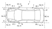
- FIG. 2 is an exemplary plan view of the vehicle.
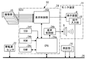
- FIG. 3 is a block diagram illustrating the configuration of the vehicle.
- FIG. 4 is a block diagram illustrating functions of the ECU.
- FIG. 5 is a flowchart of image switching processing executed by the control unit.
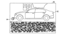
- FIG. 6 is a diagram illustrating an example of a display image including a peripheral image whose viewpoint has been changed.
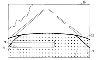
- FIG. 7 is a diagram illustrating an example of a display image according to the second embodiment.
- FIG. 1 is an exemplary perspective view showing a state in which a part of a compartment 2a of the vehicle 1 of the first embodiment is seen through.
- the vehicle 1 is an example of a moving body.
- the vehicle 1 may be, for example, an automobile (an internal combustion engine automobile) using an internal combustion engine (engine, not shown) as a drive source, or an automobile (electric vehicle) using an electric motor (motor, not shown) as a drive source. Or a fuel cell vehicle or the like, or a vehicle (hybrid vehicle) using both of them as drive sources.
- the vehicle 1 can be mounted with various transmissions, and various devices (systems, components, etc.) necessary for driving the internal combustion engine and the electric motor.
- the method, number, layout, and the like of devices related to driving of the wheels 3 in the vehicle 1 can be set in various ways.
- the vehicle 1 includes a vehicle body 2, a steering unit 4, an acceleration operation unit 5, a braking operation unit 6, a speed change operation unit 7, and a monitor device 11.
- the vehicle body 2 constitutes a passenger compartment 2a in which a passenger (not shown) gets.
- a passenger facing the driver's seat 2b as an occupant, the steering unit 4, the acceleration operation unit 5, the braking operation unit 6, the transmission operation unit 7, the display device 8, the audio output device 9, and the operation input Part 10 etc. are provided.
- the vehicle body 2 includes a front bumper provided at the lower portion of the front end portion, a rear bumper provided at the lower portion of the rear end portion, and the like.
- the steering unit 4 is, for example, a steering wheel protruding from the dashboard.
- the acceleration operation unit 5 is, for example, an accelerator pedal positioned under the driver's feet.
- the braking operation unit 6 is, for example, a brake pedal that is positioned under the driver's feet.
- the shift operation unit 7 is, for example, a shift lever that protrudes from the center console.
- the steering unit 4, the acceleration operation unit 5, the braking operation unit 6, and the speed change operation unit 7 are not limited to these.
- the monitor device 11 is provided, for example, at the center of the dashboard in the vehicle width direction, that is, the left-right direction.
- the monitor device 11 may have a function such as a navigation system or an audio system, for example.
- the monitor device 11 includes a display device 8, an audio output device 9, and an operation input unit 10.
- the monitor device 11 may have an operation input unit (not shown) such as a switch, a dial, a joystick, and a push button.
- Display device 8 displays an image based on the image information.
- the display device 8 is, for example, an LCD (Liquid Crystal Display) or an OELD (Organic Electroluminescent Display).
- the audio output device 9 outputs audio based on the audio data.
- the audio output device 9 is, for example, a speaker.
- the audio output device 9 may be provided at a different position in the passenger compartment 2a other than the monitor device 11.
- the operation input unit 10 receives an occupant's input.
- the operation input unit 10 is, for example, a touch panel.
- the operation input unit 10 is provided on the display screen of the display device 8.
- the operation input unit 10 is configured to transmit an image displayed by the display device 8. Thereby, the operation input part 10 can make a passenger
- the operation input unit 10 receives an instruction input by the occupant touching a position corresponding to an image displayed on the display screen of the display device 8.
- FIG. 2 is an exemplary plan view of the vehicle 1.
- the vehicle 1 is, for example, a four-wheeled vehicle, and includes two left and right front wheels 3 ⁇ / b> F and two right and left rear wheels 3 ⁇ / b> R. All or a part of the four wheels 3 can be steered.
- the vehicle 1 includes a plurality of imaging units 15 which are an example of a generation unit.
- the imaging unit 15 is a digital camera that incorporates an imaging element such as a CCD (Charge Coupled Device) or a CIS (CMOS Image Sensor).
- the imaging unit 15 can output moving image or still image data including a plurality of frame images generated at a predetermined frame rate as captured image data.
- the imaging unit 15 captures an image of the periphery of the vehicle 1 including an object existing around the vehicle 1 to generate a captured image, and outputs data of the captured image.
- the captured image may be a moving image or a still image.
- the captured image is an example of object information regarding objects around the vehicle 1.
- Each of the imaging units 15 includes a wide-angle lens or a fish-eye lens, and can capture a range of 140 ° to 190 ° in the horizontal direction.
- the optical axis of the imaging unit 15 is set obliquely downward. Therefore, the imaging unit 15 outputs captured image data obtained by imaging the road surface on which the vehicle 1 is movable and the external environment around the vehicle 1 including the area where the vehicle 1 can be parked.
- the vehicle 1 may have four or less or seven or more imaging units 15.
- the imaging unit 15a is installed, for example, at the left end portion 2c in front of the vehicle 1, and is provided at the upper left portion of the front bumper.
- the imaging unit 15 a images a part of the left side of the front end of the vehicle 1 and the surrounding environment on the left side in front of the vehicle 1.
- the imaging unit 15b is installed, for example, at the right end portion 2d in front of the vehicle 1 and is provided at the upper right portion of the front bumper.
- the imaging unit 15 b captures a part of the right side of the front end of the vehicle 1 and the surrounding environment on the right side in front of the vehicle 1.
- the imaging unit 15a and the imaging unit 15b also function as a stereo camera that images the same object existing in front.
- the imaging unit 15c is installed, for example, on the left end 2e on the rear side of the vehicle 1, and is provided on the left upper part of the rear bumper.
- the imaging unit 15 c images a part of the left side of the rear end of the vehicle 1 and the surrounding environment on the left side behind the vehicle 1.
- the imaging unit 15d is installed, for example, at the right end 2f behind the vehicle 1 and is provided at the upper right side of the rear bumper.
- the imaging unit 15 d captures a part of the right side at the rear end of the vehicle 1 and the surrounding environment on the right side behind the vehicle 1.
- the imaging unit 15c and the imaging unit 15d also function as a stereo camera that images the same object existing behind.
- the imaging unit 15e is provided on the left end of the vehicle body 2, for example, the left door mirror 2g.
- the imaging unit 15 e captures the environment around the left side of the vehicle 1.
- the imaging unit 15f is provided on the right end of the vehicle body 2, for example, the right door mirror 2h.
- the imaging unit 15 f captures the surrounding environment on the right side of the vehicle 1.
- the vehicle 1 includes a plurality of distance measuring units 16.
- the distance measuring unit 16 is, for example, a laser scanner.
- the distance measuring unit 16 scans in a direction intersecting with the irradiation direction while irradiating the laser beam.
- the distance measuring unit 16 receives the laser beam reflected by the object.
- the distance measurement unit 16 outputs the time from the laser light irradiation to the light reception and the irradiation direction as distance measurement information for specifying the direction of the object and measuring the distance to the object.
- the vehicle 1 includes two distance measuring units 16a and 16b.
- the distance measuring unit 16a is installed at the center of the front end of the vehicle 1, for example.
- the distance measuring unit 16a outputs distance measurement information for measuring the distance to a front object.
- the distance measuring unit 16b is installed at the center of the rear end of the vehicle 1, for example.
- the distance measuring unit 16b outputs distance measurement information for measuring a distance to a rear object.
- FIG. 3 is a block diagram illustrating the configuration of the vehicle 1. As shown in FIG. 3, the vehicle 1 further includes a wheel speed sensor 22, an ECU (Electronic Control Unit) 24, and an in-vehicle network 25.
- the monitor device 11, the imaging unit 15, and the ECU 24 function as the periphery monitoring device 50.
- the wheel speed sensor 22 is a sensor that detects the amount of rotation of the wheel 3 and the number of rotations per unit time.
- the wheel speed sensor 22 outputs a wheel speed pulse number indicating the detected rotation speed as a sensor value.
- the wheel speed sensor 22 may be configured using, for example, a hall element.
- the ECU 24 is, for example, a computer.
- the ECU 24 receives captured image data from the imaging unit 15.
- the ECU 24 transmits data related to the image or sound to be output to the monitor device 11.
- the ECU 24 includes a CPU (Central Processing Unit) 24a, a ROM (Read Only Memory) 24b, a RAM (Random Access Memory) 24c, a display control unit 24d, a voice control unit 24e, an SSD (Solid State Drive) 24f, Is provided.
- the CPU 24a, ROM 24b, and RAM 24c may be integrated in the same package.
- the CPU 24a reads a program stored in a nonvolatile storage device such as the ROM 24b, and executes various arithmetic processes and controls according to the program. For example, the CPU 24a executes image processing such as a peripheral monitoring image displayed on the display device 8.
- the ROM 24b stores each program and parameters necessary for executing the program.
- the RAM 24c temporarily stores various types of data used in computations by the CPU 24a.
- the display control unit 24 d mainly performs image processing of an image obtained by the imaging unit 15, data conversion of a display image to be displayed on the display device 8, etc., among arithmetic processing in the ECU 24.
- the voice control unit 24e mainly executes voice processing to be output to the voice output device 9 among the arithmetic processing in the ECU 24.
- the SSD 24f is a rewritable nonvolatile storage unit, and maintains data even when the power of the ECU 24 is turned off.
- the ECU 24 governs overall control of the vehicle 1 by cooperation of hardware and software (control program). For example, the ECU 24 calculates the amount of movement of the vehicle 1 and the vehicle speed based on the sensor value acquired from the wheel speed sensor 22, and executes various controls.
- the ECU 24 generates a display image including the peripheral image based on the captured image including the peripheral image captured by the imaging unit 15 and causes the display device 8 to display the display image.
- the ECU 24 generates a display image including a peripheral image whose viewpoint is changed. Thereby, the ECU 24 realizes a function as the periphery monitoring device 50.
- the in-vehicle network 25 is, for example, a CAN (Controller Area Network).
- the in-vehicle network 25 electrically connects the ECU 24, the distance measuring unit 16, the operation input unit 10, and the wheel speed sensor 22 so that information such as control signals and operation signals can be transmitted and received.
- FIG. 4 is a block diagram showing functions of the ECU 24.
- the ECU 24 includes a control unit 30 and a storage unit 32.
- the control unit 30 is realized as a function of the CPU 24a, the display control unit 24d, and the sound control unit 24e.
- the storage unit 32 is realized as a function of the ROM 24b, the RAM 24c, and the SSD 24f.
- the control unit 30 When the height of an object around the vehicle 1 specified from the captured image acquired from the imaging unit 15 satisfies a predetermined condition, the control unit 30 is a display image including the image of the object, The display device 8 is caused to display a display image in which the viewpoint of the peripheral image that is the image of the image is changed.
- the control unit 30 includes a determination unit 52 and an output unit 54.
- the control unit 30 functions as the determination unit 52 and the output unit 54 by, for example, reading an image switching processing program stored in the storage unit 32. Note that a part or all of the determination unit 52 and the output unit 54 may be configured by hardware such as a circuit including an ASIC (Application Specific Integrated Circuit).
- ASIC Application Specific Integrated Circuit
- the determination unit 52 calculates the vehicle speed from the sensor value acquired from the wheel speed sensor 22.
- the determination unit 52 causes the output unit 54 to display a peripheral image based on the vehicle speed. For example, when the vehicle speed is less than a predetermined threshold vehicle speed, the determination unit 52 outputs a first switching instruction to the output unit 54 to switch from the navigation image for road guidance to the surrounding image.
- the determination unit 52 calculates a distance to a surrounding object based on a plurality of captured images obtained by capturing the periphery by the imaging unit 15. For example, the determination unit 52 calculates the distance to the front object based on the captured images of the front periphery acquired from the imaging units 15a and 15b. The determination unit 52 determines whether or not the distance to the object is smaller than a predetermined threshold distance.
- the determination unit 52 determines that the distance to the object is smaller than a predetermined threshold distance, the determination unit 52 specifies the height of the surrounding object based on the captured image obtained by imaging the periphery. For example, when the vehicle 1 is moving forward, the determination unit 52 specifies the height of the front object based on the captured images of the front surroundings acquired from the imaging units 15a and 15b. Further, when the vehicle 1 is moving rearward, the determination unit 52 specifies the height of the rear object based on the rear surrounding captured images acquired from the imaging units 15c and 15d. The determination unit 52 determines whether or not the height of the identified object satisfies a predetermined condition.
- the predetermined condition is preferably a condition in which an object that can enter the blind spot of the occupant can be detected by the vehicle body 2 and the like, and an object that can contact the vehicle body 2 can be detected.
- An example of the predetermined condition is that the height of the object is lower than the threshold height lower than the height of the vehicle 1 (an example of the first condition) and higher than the height of the bottom of the vehicle body 2.
- the threshold height is, for example, the vehicle height (that is, the height of the highest part of the vehicle body 2), the height of the top surface of the bonnet, lower than the viewpoint of the passenger, and the vehicle body (for example, the hood) as viewed from the passenger. It is a predetermined height such as a height entering the blind spot.
- the determination unit 52 determines whether the height of the object is lower than the threshold height and higher than the bottom of the vehicle body 2. When the height of the object is lower than the threshold height and higher than the bottom of the vehicle body 2, the determination unit 52 outputs a second switching instruction for changing the viewpoint of the surrounding image to the output unit 54. In other words, when the distance to the object is smaller than the predetermined threshold distance and the height of the object satisfies the predetermined condition, the determination unit 52 changes the viewpoint of the surrounding image and displays it. Is output to the output unit 54.
- the output unit 54 outputs information to the occupant.
- the output unit 54 causes the display device 8 to display an image and output the image, and causes the sound output device 9 to output sound.
- the output unit 54 causes the display device 8 to display a navigation image for road guidance.
- the output unit 54 when acquiring the first switching instruction, the output unit 54 generates a peripheral image that is a peripheral image of the vehicle 1 from the captured image based on the captured image captured by the imaging unit 15 and causes the display device 8 to display the generated peripheral image.
- the output unit 54 may generate a peripheral image by performing image processing on the captured images captured by the plurality of imaging units 15 and then combining them.
- the output unit 54 may generate a peripheral image by correcting the distortion of the captured image by image processing.
- the output unit 54 generates a plurality of peripheral images having different viewpoints from the plurality of captured images.
- the output unit 54 generates a plurality of peripheral images by changing the viewpoint by converting the captured image according to the conversion information of the mapping table stored in the storage unit 32.
- the output unit 54 includes a front or rear periphery of the vehicle 1 and a peripheral image of the vehicle 1 viewed from the front or rear viewpoint, and a periphery and vehicle from the right or left viewpoint of the vehicle 1. A peripheral image in which 1 is viewed is generated.
- the output unit 54 When the output unit 54 acquires the second switching instruction from the determination unit 52, the output unit 54 automatically generates a display image including an image of the object and including a peripheral image whose viewpoint has been changed, and causes the display device 8 to display the display image. .
- the output unit 54 displays a display image including a peripheral image viewed from the front or rear viewpoint of the vehicle 1 in the traveling direction.
- a display image including a peripheral image based on a viewpoint changed from the viewpoint of the peripheral image of the display image is displayed on the display device 8.
- the output unit 54 uses the viewpoint as the vehicle.
- the output unit 54 generates a display image including a peripheral image obtained by viewing the periphery of the vehicle 1 including the object from the left viewpoint, and causes the display device 8 to display the display image.
- the output unit 54 may display a display image including an image under the floor of the vehicle 1. Further, the output unit 54 may display a preset three-dimensional model image superimposed on the position of the object in the display image.
- the storage unit 32 stores a program executed by the control unit 30 and parameters necessary for executing the program. For example, the storage unit 32 stores a program for image switching processing. The storage unit 32 determines whether or not to switch a threshold vehicle speed for determining whether to display a three-dimensional model image and a peripheral image necessary for execution of a program for image switching processing, and a viewpoint of the peripheral image. The threshold distance, the threshold height used for determining a predetermined condition, the height of the bottom of the vehicle body 2, and the like are stored.
- the storage unit 32 may be a storage device (for example, a cloud) provided on the network.
- FIG. 5 is a flowchart of the image switching process executed by the control unit 30.
- the control unit 30 functions as the determination unit 52 and the output unit 54 by reading a program for image switching processing, and executes image switching processing.
- the determination unit 52 determines whether or not to display a peripheral image (S102). For example, the determination unit 52 determines whether or not to display a peripheral image depending on whether or not the vehicle speed of the vehicle 1 calculated from the sensor value acquired from the wheel speed sensor 22 is less than the threshold vehicle speed. An example of the threshold vehicle speed is 10 km / h. In this case, the determination unit 52 determines to display a peripheral image when the vehicle speed is less than the threshold vehicle speed. On the other hand, the determination part 52 determines not to display the surrounding image when the vehicle speed is equal to or higher than the threshold vehicle speed. The determination unit 52 may determine whether or not to display a peripheral image based on a user operation instruction received via the operation input unit 10.
- the determination unit 52 determines not to display the surrounding image, the determination unit 52 enters a standby state (S102: No). If the determination unit 52 determines to display a peripheral image (S102: Yes), the determination unit 52 outputs a first switching instruction to the output unit 54.
- the output unit 54 When the output unit 54 acquires the first switching instruction, the output unit 54 generates a peripheral image and displays it on the display device 8 (S104). For example, the output unit 54 causes the display device 8 to display a peripheral image centered in the traveling direction (for example, forward) among peripheral images that have been subjected to image processing for removing distortion from the captured image.
- the traveling direction for example, forward
- the determination unit 52 determines whether or not the distance to the object existing in the traveling direction is smaller than the threshold distance (S106). For example, the determination unit 52 calculates the distance to the object based on the distance measurement information acquired from the distance measurement unit 16a. Note that the determination unit 52 may calculate the distance from the captured image to the object. For example, when the vehicle 1 is traveling forward, the determination unit 52 acquires captured images from the imaging units 15a and 15b. The determination unit 52 calculates the distance to the object from the image of the object included in the captured image of the imaging unit 15a and the image of the object included in the captured image of the imaging unit 15b. The determination unit 52 determines whether the calculated distance is less than the threshold distance.
- the threshold distance is preferably set based on a distance or the like at which the object becomes a blind spot of the driver.
- the threshold distance is a distance until a straight line connecting the front end (or rear end) of the roof of the vehicle body 2 and the front end (or rear end) of the vehicle body 2 intersects the ground. If the determination part 52 determines with the said distance not being smaller than a threshold distance (S106: No), it will be in a standby state. Even if the distance is less than the threshold distance, the determination unit 52 recognizes that the object is being recognized from the captured image of the imaging unit 15 and is currently determining (that is, operating) to the display device 8 during the standby. It may be displayed.
- the determination unit 52 determines whether the height of the object satisfies a predetermined condition (S108). For example, when the vehicle 1 is traveling forward, the determination unit 52 determines the size of the object image included in the captured images acquired from the imaging units 15a and 15b, the enlargement / reduction rate of the imaging units 15a and 15b, and The height of the object is calculated based on the distance to the object. The determination unit 52 determines whether or not the calculated height of the object satisfies a predetermined condition.
- the predetermined condition in the present embodiment is that the height of the object is lower than the threshold height and higher than the bottom of the vehicle body 2.
- An example of an object that satisfies the condition is a wheel stopper (or wheel stopper) or a curb stone installed in a parking lot or the like.
- the determination unit 52 determines that the height of the object does not satisfy the condition (S108: No), and the display image The display of the displayed display image is continued without changing the viewpoint of the surrounding image of the image, and the image switching process is terminated.
- the determination unit 52 determines that the height of the object satisfies the condition (S108: Yes) and performs the second switching.
- the instruction is output to the output unit 54.
- the output unit 54 When the output unit 54 acquires the second switching instruction, the output unit 54 generates a peripheral image with a changed viewpoint, and generates a display image including the peripheral image (S110).
- FIG. 6 is an example of a display image 60 including a peripheral image whose viewpoint has been changed.
- the output unit 54 performs image processing such as distortion deletion from the captured image acquired from the imaging unit 15e, and then converts the viewpoint of the captured image into a peripheral image converted to the side (for example, left).
- the output unit 54 may apply a past image captured in the past and stored in the storage unit 32 such as a ring buffer, when an underfloor image of the vehicle 1 is superimposed on a peripheral image.
- the output unit 54 superimposes a vehicle image 62 that is an image of the vehicle 1 that is set in advance and stored in the storage unit 32 on the position of the vehicle 1 in the surrounding image.
- the output unit 54 superimposes the vehicle image 62 including the wheels 3 of the vehicle 1 in order to make the occupant recognize the sense of distance between the object and the wheels 3. Further, the output unit 54 superimposes the three-dimensional model image 64 of the object set in advance and stored in the storage unit 32 on the position of the object in the peripheral image.
- a plurality of model images of the object are preferably stored in the storage unit 32 in association with the shape and size of the object.
- the model image of the object is preferably associated with the shape and size of a ring stopper, a curb, a speed breaker, or the like.
- the output unit 54 extracts the model image 64 associated with the shape and size of the identified object from the captured images of the imaging units 15a and 15b, and superimposes the model image 64 on the surrounding image.
- the output unit 54 may set a color of the model image 64 in advance, but may select a color (for example, a complementary color or an opposite color) different from the color around the object to color the model image 64. .
- the output unit 54 may color only the area of the model image 64 in contact with the vehicle body 2. Further, the output unit 54 may give a pattern such as a mesh to the model image 64 instead of the color.
- the output unit 54 displays the generated display image 60 as shown in FIG. 6 on the display device 8 (S112). Thereby, the output unit 54 ends the image switching process.
- the periphery monitoring device 50 causes the display device 8 to display the display image 60 including the periphery image obtained by converting the viewpoint when the height of the object satisfies a predetermined condition.
- the periphery monitoring apparatus 50 can make a passenger
- the periphery monitoring device 50 is particularly likely to enter the blind spot of the occupant. The occupant can easily recognize the object.
- the periphery monitoring device 50 Since the periphery monitoring device 50 superimposes the preset three-dimensional model image 64 on the position of the object in the peripheral image whose viewpoint has been switched, it can be made conspicuous with respect to the peripheral image. Thereby, the periphery monitoring apparatus 50 can make a passenger
- the periphery monitoring device 50 calculates the distance to the object by the imaging unit 15 and generates the display image 60 including the periphery image, the configuration can be simplified. Furthermore, since the periphery monitoring device 50 includes a plurality of imaging units 15a and 15b that function as a stereo camera that captures the same object in front, it also detects low objects that cannot be detected by sonar using ultrasonic waves, etc. The height of the object and the distance to the object can be specified. Accordingly, the periphery monitoring device 50 can more accurately determine whether or not the object satisfies the condition, and can switch the viewpoint of the surrounding image in a more appropriate situation.
- the periphery monitoring device 50 While displaying the display image including the peripheral image viewed from the front viewpoint of the vehicle 1 and displaying the front image of the vehicle 1, the periphery monitoring device 50 switches to the display image 60 including the peripheral image viewed from the left viewpoint where the viewpoint is changed. Therefore, the uncomfortable feeling due to switching of the display image 60 can be reduced.
- the periphery monitoring device 50 displays the display image 60 including the underfloor image and the surrounding image of the vehicle 1 by changing the viewpoint, it is possible to notify the occupant of the underfloor state.
- FIG. 7 is a diagram illustrating an example of the display image 70 according to the second embodiment.
- the output unit 54 displays a display including a peripheral image whose viewpoint is converted upward as shown in FIG. An image 70 is generated and displayed on the display device 8.
- the output unit 54 displays a vehicle body image 72 of the vehicle body 2 on the traveling direction side (for example, the front side) of the vehicle 1 indicated by a dotted area surrounded by a bold line, and a wheel image 73 indicating a part of the wheel 3 indicated by a dotted line. You may superimpose on a peripheral image.
- the output unit 54 may transmit the vehicle body image 72.
- the output unit 54 may superimpose a model image 74 of the object on the vehicle body image 72 when the object exists in the blind spot by the vehicle 1.
- the display image 60 or 70 including the peripheral image from the side is displayed on the entire display device 8 by changing the viewpoint, but the output unit 54 changes the viewpoint together with the peripheral image. You may display the display image which combined other images, such as a peripheral image which is not.
- the determination unit 52 determines whether or not to change the viewpoint of the surrounding image depending on whether or not the shape of the object specified from the object information (for example, the captured image) satisfies a predetermined condition.
- the predetermined condition is, for example, that the shape of the object is a shape stored in advance in the storage unit 32 (an example of a second condition).
- the object may be a marker that informs the existence of a non-contact power supply system that supplies power to the storage battery in a non-contact manner.
- the determination unit 52 may change the viewpoint of the surrounding image when the shape of the marker specified from the object information satisfies a predetermined condition.
- the output unit 54 may display the display image with the image under the floor of the vehicle 1 as a part of the peripheral image. Further, the determination unit 52 may change the viewpoint of the surrounding image when the height of the object specified from the object information or the shape of the object satisfies a predetermined condition.
- a peripheral image whose viewpoint is changed with respect to a front or rear object is displayed.
- the present invention is not limited to this.
- the model is emphasized by changing the color of the object.
- You may display the peripheral image (for example, bird's-eye view image) which changed the viewpoint with the image.
- the predetermined conditions set in the above embodiment may be changed as appropriate.
- the viewpoint of the surrounding image is changed. It may be configured.
- a plurality of conditions may be set.
- the second height condition may be lower than the threshold height and lower than the bottom of the vehicle body 2 such as a bumper.
- the output unit 54 acquires a second switching instruction to the effect that the first height condition is satisfied from the determination unit 52, and the object is the vehicle body.
- the output unit 54 Before reaching 2 (for example, a bumper), a peripheral image whose viewpoint has been converted is displayed. In this case, the output unit 54 may output a warning by voice according to the distance between the end of the vehicle body 2 such as a bumper and the object. On the other hand, when the height of the object satisfies the second height condition, the output unit 54 acquires a third switching instruction indicating that the second height condition is satisfied from the determination unit 52, and the object reaches the vehicle body 2. Before the wheel 3 is reached, a peripheral image whose viewpoint has been converted is displayed. In this case, the output unit 54 may output a warning by voice according to the distance between the wheel 3 and the object.
- an example in which an object protrudes upward is given, but the present invention is not limited to this.
- it may be a step where the object is lowered.
- the determination unit 52 determines whether or not the step dent amount satisfies a predetermined condition as the step height, and if the condition is satisfied, the output unit 54 converts the viewpoint.
- You may display a level
- the output unit 54 may change the color before and after the step of the step.
- control unit 30 may display a display image as shown in FIGS. 6 and 7 in which the viewpoint of the peripheral image is changed from the viewpoint of the imaging unit 15 from the navigation image for road guidance.
- the present invention is not limited to this.
- distance measurement information obtained by the distance measurement unit 16 measuring a distance to the object and a direction in which the distance is measured are output as object information, and the determination unit 52 calculates the height of the object based on the object information. Also good. In this case, the distance measurement unit 16 functions as a generation unit.
- the determination unit 52 may calculate the height of the object from one captured image acquired from one imaging unit 15.
- the determination unit 52 includes the height at which the imaging unit 15 is installed, the distance to the object acquired from the imaging unit 15, the size of the object in the captured image, the direction of the optical axis of the lens of the imaging unit 15, and the imaging unit.
- the height of the object may be calculated based on the magnification ratio of the 15 lenses.
Landscapes
- Engineering & Computer Science (AREA)
- Multimedia (AREA)
- Mechanical Engineering (AREA)
- Physics & Mathematics (AREA)
- General Physics & Mathematics (AREA)
- Theoretical Computer Science (AREA)
- General Engineering & Computer Science (AREA)
- Software Systems (AREA)
- Computer Hardware Design (AREA)
- Computer Graphics (AREA)
- Signal Processing (AREA)
- Closed-Circuit Television Systems (AREA)
- Image Analysis (AREA)
- Processing Or Creating Images (AREA)
- Image Processing (AREA)
- Traffic Control Systems (AREA)
Abstract
周辺監視装置は、移動体の周辺の物体に関する物体情報を生成する生成部と、前記物体情報から特定した前記物体の高さが予め定められた条件を満たす場合、前記物体の画像を含み、前記移動体の周辺の画像である周辺画像の視点を変更した表示画像を表示させる制御部と、を備える。
Description
本発明は、周辺監視装置に関する。
自動車等の移動体に設けられ、移動体の周辺の画像を表示する周辺監視装置が知られている。このような周辺監視装置において、移動体の周辺に存在する輪止め等の物体及び物体の周辺を他の領域と異なる表示形態で表示する技術が知られている。
しかしながら、上述の周辺監視装置では、周辺に存在する物体が車体に隠れた場合、乗員が当該物体を認識できにくいといった課題がある。
本発明は、上記に鑑みてなされたものであって、周辺の物体を乗員に容易に認識させることができる周辺監視装置を提供することを目的とする。
上述した課題を解決し、目的を達成するために、本発明の周辺監視装置は、移動体の周辺の物体に関する物体情報を生成する生成部と、前記物体情報から特定した前記物体の高さ又は前記物体の形状が予め定められた条件を満たす場合、前記物体の画像を含み、前記移動体の周辺の画像である周辺画像の視点を変更した表示画像を表示させる制御部と、を備える。
このように、周辺監視装置は、物体の高さ又は物体の形状が予め定められた条件を満たす場合、視点を変更した周辺画像を含む表示画像を表示させる。これにより、周辺監視装置は、移動体の車体等によって進行方向側の乗員等の死角となった領域に存在する周辺の物体を乗員に容易に認識させることができる。
本発明の周辺監視装置では、前記予め定められた条件は、第一の条件と第二の条件の少なくともどちらかを有し、前記第一の条件は、前記物体の高さが前記移動体の高さよりも低い閾値高さよりも低いであって、前記第二の条件は、前記物体の形状が予め記憶された形状であることであって、前記制御部は、前記第一の条件と前記第二の条件の少なくともどちらかを満たす場合、前記周辺画像の前記視点を変更して表示させてもよい。これにより、周辺監視装置は、特に乗員の死角に入りやすい物体及び認識させたい形状の物体等を乗員に容易に認識させることができる。
本発明の周辺監視装置では、前記制御部は、予め設定された前記物体の3次元のモデル画像を前記表示画像内の前記物体の位置に重畳させて表示させてもよい。これにより、周辺監視装置は、モデル画像によって乗員に物体をより容易に認識させることができる。
本発明の周辺監視装置では、前記生成部は、前記物体情報を生成するために前記移動体の周辺を撮像して撮像画像を生成する少なくとも一つの撮像部を含み、前記制御部は、前記撮像画像から算出した前記物体までの距離が予め定められた閾値距離より小さく、かつ、前記物体情報から特定した前記物体の高さ又は前記物体の形状が前記予め定められた条件を満たす場合、前記撮像画像から生成された前記周辺画像の視点を変更した前記表示画像を表示させてもよい。これにより、周辺監視装置は、撮像部によって生成された撮像画像から物体までの距離を算出するとともに周辺画像を生成するので、構成を簡略化できる。
本発明の周辺監視装置では、前記制御部は、前記物体情報から特定した前記物体の高さが前記予め定められた条件を満たす場合、表示中の前記表示画像の前記周辺画像の視点から変更した視点による周辺画像を含む前記表示画像を表示させてもよい。これにより、周辺監視装置は、表示中の表示画像の視点を変更した周辺画像を含む表示画像を表示させることにより、表示画像の切り替わりによる違和感を低減できる。
本発明の周辺監視装置では、前記制御部は、前記物体情報から特定した前記物体の高さが前記予め定められた条件を満たす場合、前記移動体の床下の画像を含む表示画像を表示させてもよい。これにより、周辺監視装置は、乗員に床下の状態を知らせることができる。
以下の例示的な実施形態等の同様の構成要素には共通の符号を付与して、重複する説明を適宜省略する。
<第1実施形態>
図1は、第1実施形態の車両1の車室2aの一部が透視された状態が示された例示的な斜視図である。車両1は、移動体の一例である。車両1は、例えば、内燃機関(エンジン、図示されず)を駆動源とする自動車(内燃機関自動車)であってもよいし、電動機(モータ、図示されず)を駆動源とする自動車(電気自動車、燃料電池自動車等)であってもよいし、それらの双方を駆動源とする自動車(ハイブリッド自動車)であってもよい。また、車両1は、種々の変速装置を搭載することができるし、内燃機関や電動機を駆動するのに必要な種々の装置(システム、部品等)を搭載することができる。また、車両1における車輪3の駆動に関わる装置の方式、個数、及び、レイアウト等は、種々に設定することができる。
図1は、第1実施形態の車両1の車室2aの一部が透視された状態が示された例示的な斜視図である。車両1は、移動体の一例である。車両1は、例えば、内燃機関(エンジン、図示されず)を駆動源とする自動車(内燃機関自動車)であってもよいし、電動機(モータ、図示されず)を駆動源とする自動車(電気自動車、燃料電池自動車等)であってもよいし、それらの双方を駆動源とする自動車(ハイブリッド自動車)であってもよい。また、車両1は、種々の変速装置を搭載することができるし、内燃機関や電動機を駆動するのに必要な種々の装置(システム、部品等)を搭載することができる。また、車両1における車輪3の駆動に関わる装置の方式、個数、及び、レイアウト等は、種々に設定することができる。
図1に示すように、車両1は、車体2と、操舵部4と、加速操作部5と、制動操作部6と、変速操作部7と、モニタ装置11とを備える。
車体2は、不図示の乗員が乗車する車室2aを構成している。車室2a内には、乗員としての運転者の座席2bに臨む状態で、操舵部4、加速操作部5、制動操作部6、変速操作部7、表示装置8、音声出力装置9、操作入力部10等が設けられている。車体2は、前端部の下部に設けられたフロントバンパー及び後端部の下部に設けられたリアバンパー等を含む。
操舵部4は、例えば、ダッシュボードから突出したステアリングホイールである。加速操作部5は、例えば、運転者の足下に位置されたアクセルペダルである。制動操作部6は、例えば、運転者の足下に位置されたブレーキペダルである。変速操作部7は、例えば、センターコンソールから突出したシフトレバーである。なお、操舵部4、加速操作部5、制動操作部6、及び、変速操作部7は、これらには限定されない。
モニタ装置11は、例えば、ダッシュボードの車幅方向すなわち左右方向の中央部に設けられている。モニタ装置11は、例えば、ナビゲーションシステムまたはオーディオシステム等の機能を有してもよい。モニタ装置11は、表示装置8、音声出力装置9、及び、操作入力部10を有する。モニタ装置11は、スイッチ、ダイヤル、ジョイスティック、及び、押しボタン等の不図示の操作入力部を有してもよい。
表示装置8は、画像情報に基づいて画像を表示する。表示装置8は、例えば、LCD(Liquid Crystal Display)、または、OELD(Organic Electroluminescent Display)等である。
音声出力装置9は、音声データに基づいて音声を出力する。音声出力装置9は、例えば、スピーカである。音声出力装置9は、モニタ装置11以外の異なる車室2a内の位置に設けられていてもよい。
操作入力部10は、乗員の入力を受け付ける。操作入力部10は、例えば、タッチパネルである。操作入力部10は、表示装置8の表示画面に設けられている。操作入力部10は、表示装置8が表示する画像を透過可能に構成されている。これにより、操作入力部10は、表示装置8の表示画面に表示される画像を乗員に視認させることができる。操作入力部10は、表示装置8の表示画面に表示される画像に対応した位置を乗員が触れることによって入力した指示を受け付ける。
図2は、車両1の例示的な平面図である。図1及び図2に示すように、車両1は、例えば、四輪自動車であり、左右二つの前輪3Fと、左右二つの後輪3Rとを有する。四つの車輪3の全てまたは一部は、転舵可能である。
車両1は、生成部の一例である複数の撮像部15を備える。撮像部15は、例えば、CCD(Charge Coupled Device)、または、CIS(CMOS Image Sensor)等の撮像素子を内蔵するデジタルカメラである。撮像部15は、所定のフレームレートで生成される複数のフレーム画像を含む動画、または、静止画のデータを撮像画像のデータとして出力できる。例えば、撮像部15は、車両1の周辺に存在する物体を含む車両1の周辺を撮像して撮像画像を生成し、当該撮像画像のデータを出力する。撮像画像は、動画または静止画であってよい。撮像画像は、車両1の周辺の物体に関する物体情報の一例である。撮像部15は、それぞれ、広角レンズまたは魚眼レンズを有し、水平方向の140°~190°の範囲を撮影することができる。撮像部15の光軸は、斜め下方に向けて設定されている。従って、撮像部15は、車両1が移動可能な路面、及び、車両1が駐車可能な領域を含む車両1の周辺の外部の環境を撮像した撮像画像データを出力する。
本実施形態では、6個の撮像部15a、15b、15c、15d、15e、15fが車両1に設けられている。車両1は、4個以下または7個以上の撮像部15を有してもよい。撮像部15aは、例えば、車両1の前方の左側の端部2cに設置され、フロントバンパーの左側の上部に設けられている。撮像部15aは、車両1の前端の左側の一部、及び、車両1の前方の左側の周辺の環境を撮影する。撮像部15bは、例えば、車両1の前方の右側の端部2dに設置され、フロントバンパーの右側の上部に設けられている。撮像部15bは、車両1の前端の右側の一部、及び、車両1の前方の右側の周辺の環境を撮影する。撮像部15a及び撮像部15bは、前方に存在する同じ物体を撮像するステレオカメラとしても機能する。撮像部15cは、例えば、車両1の後方の左側の端部2eに設置され、リアバンパーの左側の上部に設けられている。撮像部15cは、車両1の後端の左側の一部、及び、車両1の後方の左側の周辺の環境を撮影する。撮像部15dは、例えば、車両1の後方の右側の端部2fに設置され、リアバンパーの右側の上部に設けられている。撮像部15dは、車両1の後端の右側の一部、及び、車両1の後方の右側の周辺の環境を撮影する。撮像部15c及び撮像部15dは、後方に存在する同じ物体を撮像するステレオカメラとしても機能する。撮像部15eは、車体2の左側の端部、例えば、左側のドアミラー2gに設けられている。撮像部15eは、車両1の左側の周辺の環境を撮影する。撮像部15fは、車体2の右側の端部、例えば、右側のドアミラー2hに設けられている。撮像部15fは、車両1の右側の周辺の環境を撮影する。
車両1は、複数の測距部16を備える。測距部16は、例えば、レーザスキャナである。測距部16は、レーザ光を照射しつつ照射方向と交差する方向で走査する。測距部16は、物体に反射されたレーザ光を受光する。測距部16は、レーザ光の照射から受光までの時間及び照射方向を、物体の方向を特定するとともに物体までの距離を測距する測距情報として出力する。
本実施形態では、車両1は、2個の測距部16a、16bを備える。測距部16aは、例えば、車両1の前端部の中央に設置されている。測距部16aは、前方の物体までの距離を測距する測距情報を出力する。測距部16bは、例えば、車両1の後端部の中央に設置されている。測距部16bは、後方の物体までの距離を測距する測距情報を出力する。
図3は、車両1の構成を説明するブロック図である。図3に示すように、車両1は、車輪速センサ22と、ECU(Electronic Control Unit)24と、車内ネットワーク25とを更に備える。モニタ装置11、撮像部15、及び、ECU24は、周辺監視装置50として機能する。
車輪速センサ22は、車輪3の回転量や単位時間当たりの回転数を検出するセンサである。車輪速センサ22は、検出した回転数を示す車輪速パルス数をセンサ値として出力する。車輪速センサ22は、例えば、ホール素子などを用いて構成されうる。
ECU24は、例えば、コンピュータである。ECU24は、撮像部15から撮像画像データを受信する。ECU24は、出力させる画像または音声に関するデータをモニタ装置11へ送信する。ECU24は、CPU(Central Processing Unit)24aと、ROM(Read Only Memory)24bと、RAM(Random Access Memory)24cと、表示制御部24dと、音声制御部24eと、SSD(Solid State Drive)24fとを備える。CPU24a、ROM24b及びRAM24cは、同一パッケージ内に集積されていてもよい。
CPU24aは、ROM24b等の不揮発性の記憶装置に記憶されたプログラムを読み出し、当該プログラムにしたがって各種の演算処理および制御を実行する。CPU24aは、例えば、表示装置8に表示させる周辺監視用の画像等の画像処理を実行する。
ROM24bは、各プログラム及びプログラムの実行に必要なパラメータ等を記憶する。RAM24cは、CPU24aでの演算で用いられる各種のデータを一時的に記憶する。表示制御部24dは、ECU24での演算処理のうち、主として、撮像部15で得られた画像の画像処理、表示装置8に表示させる表示用の画像のデータ変換等を実行する。音声制御部24eは、ECU24での演算処理のうち、主として、音声出力装置9に出力させる音声の処理を実行する。SSD24fは、書き換え可能な不揮発性の記憶部であって、ECU24の電源がオフされた場合にあってもデータを維持する。
本実施形態では、ECU24は、ハードウェアとソフトウェア(制御プログラム)が協働することにより、車両1の制御全般を司る。例えば、ECU24は、車輪速センサ22から取得したセンサ値に基づいて車両1の移動量及び車速などを演算し、各種制御を実行する。ECU24は、撮像部15が撮像した周辺の画像を含む撮像画像に基づいて、周辺画像を含む表示画像を生成して、表示装置8に表示させる。ECU24は、例えば、視点を変化させた周辺画像を含む表示画像を生成する。これにより、ECU24は、周辺監視装置50としての機能を実現している。
車内ネットワーク25は、例えば、CAN(Controller Area Network)である。車内ネットワーク25は、ECU24と、測距部16と、操作入力部10と、車輪速センサ22とを互いに制御信号及び操作信号等の情報を送受信可能に電気的に接続する。
図4は、ECU24の機能を示すブロック図である。図4に示すように、ECU24は、制御部30と、記憶部32とを有する。制御部30は、CPU24a、表示制御部24d、及び、音声制御部24eの機能として実現される。記憶部32は、ROM24b、RAM24c、及び、SSD24fの機能として実現される。
制御部30は、撮像部15から取得した撮像画像から特定した車両1の周辺の物体の高さが予め定められた条件を満たす場合、物体の画像を含む表示画像であって、車両1の周辺の画像である周辺画像の視点を変更した表示画像を表示装置8に表示させる。制御部30は、判定部52と、出力部54とを有する。制御部30は、例えば、記憶部32に格納された画像切替処理用のプログラムを読み込むことによって、判定部52及び出力部54として機能する。尚、判定部52及び出力部54の一部または全部は、ASIC(Application Specific Integrated Circuit)を含む回路等のハードウェアによって構成してもよい。
判定部52は、車輪速センサ22から取得するセンサ値から車速を算出する。判定部52は、車速に基づいて、周辺画像を出力部54に表示させる。例えば、判定部52は、車速が予め定められた閾値車速未満の場合、第1切替指示を出力部54へ出力することによって、道案内用のナビゲーション画像から周辺画像に切り替えさせる。
判定部52は、撮像部15が周辺を撮像した複数の撮像画像に基づいて、周辺の物体までの距離を算出する。例えば、判定部52は、撮像部15a、15bから取得した前方の周辺の撮像画像に基づいて、前方の物体までの距離を算出する。判定部52は、物体までの距離が予め定められた閾値距離よりも小さいか否かを判定する。
判定部52は、物体までの距離が予め定められた閾値距離よりも小さいと判定した場合、撮像部15が周辺を撮像した撮像画像に基づいて、周辺の物体の高さを特定する。例えば、判定部52は、車両1が前方に移動している場合、撮像部15a、15bから取得した前方の周辺の撮像画像に基づいて、前方の物体の高さを特定する。また、判定部52は、車両1が後方に移動している場合、撮像部15c、15dから取得した後方の周辺の撮像画像に基づいて、後方の物体の高さを特定する。判定部52は、特定した物体の高さが予め定められた条件を満たしているか否かを判定する。予め定められた条件は、車体2等によって乗員の死角に入る可能性のある物体を検出でき、かつ、車体2と接触する可能性のある物体を検出できる条件が好ましい。予め定められた条件の一例は、物体の高さが、車両1の高さよりも低い閾値高さよりも低く(第一の条件の一例)、かつ、車体2の底部の高さよりも高いである。閾値高さは、例えば、車高(即ち、車体2の最高部の高さ)、ボンネットの天面の高さ、乗員の視点よりも低い、及び、乗員から見て車体(例えば、ボンネット)の死角に入り込む高さ等の予め定められた高さである。従って、判定部52は、物体の高さが、閾値高さよりも低く、かつ、車体2の底部より高いか否かを判定する。判定部52は、物体の高さが閾値高さよりも低くかつ車体2の底部よりも高い場合、周辺画像の視点を変更させる第2切替指示を出力部54へ出力する。換言すれば、判定部52は、物体までの距離が予め定められた閾値距離よりも小さく、かつ、物体の高さが予め定められた条件を満たす場合、周辺画像の視点を変更させて表示させるための第2切替指示を出力部54へ出力する。
出力部54は、乗員へ情報を出力する。例えば、出力部54は、表示装置8に画像を表示させて画像を出力するとともに、音声出力装置9に音声を出力させる。具体的には、出力部54は、道案内用のナビゲーション画像を表示装置8に表示させる。また、出力部54は、第1切替指示を取得すると、撮像部15が撮像した撮像画像に基づいて、車両1の周辺の画像である周辺画像を撮像画像から生成して表示装置8に表示させる。ここで、出力部54は、複数の撮像部15が撮像した撮像画像を画像処理した後、合成して周辺画像を生成してもよい。例えば、出力部54は、画像処理によって撮像画像の歪みを補正して周辺画像を生成してもよい。
また、出力部54は、複数の撮像画像から視点が異なる複数の周辺画像を生成する。例えば、出力部54は、記憶部32に格納されたマッピングテーブルの変換情報によって、撮像画像を変換することにより、視点を変更して複数の周辺画像を生成する。具体的には、出力部54は、車両1の前部または後部の視点から前方または後方の周辺及び車両1を見た周辺画像、及び、車両1の右方または左方の視点から周辺及び車両1を見た周辺画像を生成する。出力部54は、判定部52から第2切替指示を取得すると、物体の画像を含む表示画像であって、視点を変更した周辺画像を含む表示画像を自動で生成して表示装置8に表示させる。例えば、出力部54は、判定部52から第2切替指示を取得すると、車両1の前部または後部の視点から進行方向を見た周辺画像を含む表示画像を表示させている場合、表示中の表示画像の周辺画像の視点から変更した視点による周辺画像を含む表示画像を表示装置8に表示させる。具体的には、出力部54は、車両1が前方に移動中であって、車両1の前部の視点から前方を見た周辺画像を含む表示画像を表示している場合、当該視点を車両1の左方の視点に変更する。この場合、出力部54は、左方の視点から物体を含む車両1の周辺を見た周辺画像を含む表示画像を生成して、表示装置8に表示させる。ここで、出力部54は、判定部52から第2切替指示を取得して、視点を変更する場合、車両1の床下の画像を含む表示画像を表示させてもよい。また、出力部54は、予め設定された3次元のモデル画像を表示画像内の物体の位置に重畳させて表示させてもよい。
記憶部32は、制御部30が実行するプログラム及びプログラムの実行に必要なパラメータ等を記憶する。例えば、記憶部32は、画像切替処理用のプログラムを記憶する。記憶部32は、画像切替処理用のプログラムの実行に必要な3次元のモデル画像、周辺画像を表示させるか否かを判定するための閾値車速、周辺画像の視点を切り替えるか否かを判定するための閾値距離、予め定められた条件の判定に用いられる閾値高さ、及び、車体2の底部の高さ等を記憶する。尚、記憶部32はネットワーク上に設けられた記憶装置(例えば、クラウド)等であってもよい。
図5は、制御部30が実行する画像切替処理のフローチャートである。制御部30は、画像切替処理用のプログラムを読み込むことによって、判定部52及び出力部54として機能して、画像切替処理を実行する。
図5に示すように、判定部52は、周辺画像を表示するか否かを判定する(S102)。例えば、判定部52は、車輪速センサ22から取得したセンサ値から算出した車両1の車速が閾値車速未満か否かによって周辺画像を表示するか否かを判定する。閾値車速の一例は、10km/hである。この場合、判定部52は、車速が閾値車速未満の場合、周辺画像を表示すると判定する。一方、判定部52は、車速が閾値車速以上の場合、周辺画像を表示しないと判定する。尚、判定部52は、操作入力部10を介して受け付けたユーザの操作指示等に基づいて、周辺画像を表示するか否かを判定してもよい。
判定部52は、周辺画像を表示しないと判定した場合、待機状態となる(S102:No)。判定部52は、周辺画像を表示すると判定すると(S102:Yes)、第1切替指示を出力部54へ出力する。
出力部54は、第1切替指示を取得すると、周辺画像を生成して、表示装置8に表示させる(S104)。例えば、出力部54は、撮像画像から歪みを削除する画像処理を実行した周辺画像のうち、進行方向(例えば、前方)を中心とする周辺画像を表示装置8に表示させる。
判定部52は、進行方向に存在する物体までの距離が閾値距離より小さいか否かを判定する(S106)。例えば、判定部52は、測距部16aから取得した測距情報に基づいて、物体までの距離を算出する。尚、判定部52は、撮像画像から物体までの距離を算出してもよい。例えば、判定部52は、車両1が前方に進行している場合、撮像部15a、15bから撮像画像を取得する。判定部52は、撮像部15aの撮像画像に含まれる物体の画像と撮像部15bの撮像画像に含まれる物体の画像とから物体までの距離を算出する。判定部52は、算出した距離が閾値距離未満か否かを判定する。閾値距離は、物体が運転者の死角となる距離等に基づいて設定することが好ましい。例えば、閾値距離は、車体2のルーフの前端部(または後端部)と車体2の前端部(または後端部)とを結ぶ直線が地面と交差するまでの距離等である。判定部52は、当該距離が閾値距離より小さくないと判定すると(S106:No)、待機状態となる。尚、判定部52は、当該距離が閾値距離未満であっても、物体を撮像部15の撮像画像から認識して判定中(即ち、作動中)である旨を当該待機中に表示装置8に表示してもよい。
判定部52は、算出した物体までの距離が閾値距離より小さいと判定すると(S106:Yes)、物体の高さが予め定められた条件を満たすか否かを判定する(S108)。例えば、判定部52は、車両1が前方に進行している場合、撮像部15a、15bから取得した撮像画像に含まれる物体の画像の大きさ、撮像部15a、15bの拡大・縮小率、及び、物体までの距離等に基づいて、物体の高さを算出する。判定部52は、算出した物体の高さが予め定められた条件を満たすか否かを判定する。本実施形態における予め定められた条件は、物体の高さが、閾値高さよりも低く、かつ、車体2の底部よりも高いである。当該条件を満たす物体の一例は、駐車場等に設置されている輪止め(または車輪止め)または縁石等である。
物体の高さが、閾値高さよりも高く、または、車体2の底部よりも低い場合、判定部52は、物体の高さが当該条件を満たさないと判定して(S108:No)、表示画像の周辺画像の視点を変更することなく、表示中の表示画像の表示を継続して、画像切替処理を終了する。
物体の高さが、閾値高さよりも低く、かつ、車体2の底部よりも高い場合、判定部52は、物体の高さが当該条件を満たすと判定して(S108:Yes)、第2切替指示を出力部54へ出力する。
出力部54は、第2切替指示を取得すると、視点を変更した周辺画像を生成して、当該周辺画像を含む表示画像を生成する(S110)。
図6は、視点変更した周辺画像を含む表示画像60の一例の図である。例えば、出力部54は、撮像部15eから取得した撮像画像から歪みの削除等の画像処理を実行した後、当該撮像画像の視点を側方(例えば、左方)に変換した周辺画像に変換する。尚、出力部54は、車両1の床下の画像を周辺画像に重畳させる場合、過去に撮像されてリングバッファ等の記憶部32に格納された過去画像を適用してもよい。出力部54は、図6に示すように、予め設定されて記憶部32に格納された車両1の画像である車両画像62を当該周辺画像の車両1の位置に重畳させる。この場合、出力部54は、物体と車輪3との距離感を乗員に認識させるために、車両1の車輪3を含む車両画像62を重畳させることが好ましい。更に、出力部54は、予め設定されて記憶部32に格納された物体の3次元のモデル画像64を周辺画像の物体の位置に重畳させる。物体のモデル画像は、物体の形状及び大きさ等に対応付けて記憶部32に複数格納されていることが好ましい。例えば、物体のモデル画像は、輪止め、縁石、及び、スピードブレーカ等の形状及び大きさに対応付けられていることが好ましい。この場合、出力部54は、撮像部15a、15bの撮像画像から特定した物体の形状及び大きさに関連付けられたモデル画像64を抽出して、周辺画像に重畳させる。出力部54は、モデル画像64の色を予め設定された色としてもよいが、物体の周辺の色と異なる色(例えば、補色または反対色)を選択してモデル画像64を着色してもよい。尚、出力部54は、車体2と接触するモデル画像64の領域のみ着色してもよい。また、出力部54は、色に代えてメッシュ等の模様をモデル画像64に付与してもよい。
出力部54は、図6に示すような生成した表示画像60を表示装置8に表示させる(S112)。これにより、出力部54は、画像切替処理を終了する。
上述したように、周辺監視装置50は、物体の高さが予め定められた条件を満たす場合、視点を変換した周辺画像を含む表示画像60を表示装置8に表示させている。これにより、周辺監視装置50は、車体2等によって進行方向側の撮像部15及び乗員の死角となった領域に存在する周辺の物体を乗員に容易に認識させることができる。また、予め定められた条件を、物体の高さが、閾値高さよりも高く、かつ、車体2の底部の高さよりも高いとすることにより、周辺監視装置50は、特に乗員の死角に入りやすい物体を乗員に容易に認識させることができる。
周辺監視装置50は、視点を切り替えた周辺画像の物体の位置に予め設定された3次元のモデル画像64を重畳させるので、周辺画像に対して目立たせることができる。これにより、周辺監視装置50は、乗員に物体をより容易に認識させることができる。
周辺監視装置50は、撮像部15によって物体までの距離を算出するとともに周辺画像を含む表示画像60を生成するので、構成を簡略化できる。更に、周辺監視装置50は、前方の同じ物体を撮影するステレオカメラとして機能する複数の撮像部15a、15bを有するので、超音波等を使用したソナー等によって検出できない低い物体等も検出して、当該物体の高さ及び物体までの距離を特定できる。これにより、周辺監視装置50は、物体が条件を満たすか否かをより正確に判定して、より適切な状況で周辺画像の視点を切り替えることができる。
周辺監視装置50は、車両1の前部の視点から前方を見た周辺画像を含む表示画像を表示中に、当該視点を変更した左方の視点から見た周辺画像を含む表示画像60に切り替えるので、表示画像60の切り替わりによる違和感を低減できる。
周辺監視装置50は、視点の変更によって、車両1の床下の画像及び周辺画像を含む表示画像60を表示させるので、乗員に床下の状態を知らせることができる。
<第2実施形態>
上述の実施形態では、物体の高さが条件を満たした場合、出力部54は、視点を側方に変換した周辺画像を生成したが、これに限定されない。図7は、第2実施形態の表示画像70の一例を示す図である。
上述の実施形態では、物体の高さが条件を満たした場合、出力部54は、視点を側方に変換した周辺画像を生成したが、これに限定されない。図7は、第2実施形態の表示画像70の一例を示す図である。
第2実施形態では、判定部52が、物体の高さが予め定められた条件を満たすと判定すると、出力部54は、図7に示すように、視点を上方に変換した周辺画像を含む表示画像70を生成して表示装置8に表示させる。ここで、出力部54は、太線で囲むドット領域で示す車両1の進行方向側(例えば、前側)の車体2の車体画像72、及び、点線で示す車輪3の一部を示す車輪画像73を周辺画像に重畳させてもよい。この場合、出力部54は、車体画像72を透過させてもよい。更に、出力部54は、車両1によって物体が死角に存在する場合、車体画像72に物体のモデル画像74を重畳させてもよい。
上述の実施形態の各構成の機能、接続関係、配置、及び、個数等は適宜変更してよい。
上述の実施形態では、視点を変更して側方からの周辺画像を含む表示画像60、70を表示装置8の全体に表示させたが、出力部54は、当該周辺画像とともに、視点を変更していない周辺画像等の別の画像を合わせた表示画像を表示させてもよい。
上述の実施形態では、物体が輪止めであり物体の高さが予め定められた条件を満たすか否かを判定する例を挙げたが、これに限定されない。例えば、判定部52は、物体情報(例えば、撮像画像)から特定した物体の形状が予め定められた条件を満たすか否かによって、周辺画像の視点を変更するか否かを判定するようにしてもよい。予め定められた条件は、例えば、物体の形状が予め記憶部32に記憶された形状であることである(第二の条件の一例)。この場合、物体は蓄電池に電力を非接触で給電する非接触給電システムの存在を知らせるマーカであってもよい。判定部52は、物体情報から特定した当該マーカの形状が予め定められた条件を満たす場合、周辺画像の視点を変更してよい。この場合、出力部54は、車両1の床下の画像を周辺画像の一部として表示画像を表示させてもよい。また、判定部52は、物体情報から特定した物体の高さ又は物体の形状が予め定められた条件を満たすか場合、周辺画像の視点を変更するようにしてもよい。
上述の実施形態では、前方または後方の物体に対して視点を変更した周辺画像を表示する例を挙げたが、これに限定されない。例えば、車両1が右方または左方へと操舵されて進行している場合、進路上に存在する物体の高さが上述の条件を満たしている場合、物体の色を変更して強調したモデル画像とともに視点を変更した周辺画像(例えば、俯瞰画像)を表示してもよい。
上述の実施形態で設定した予め定められた条件は適宜変更してよい。例えば、物体の高さが、予め定められた条件として閾値高さよりも低い場合(即ち、物体の高さが車体2の底部の高さより高くてもよい)、周辺画像の視点を変更するように構成してもよい。また、複数の条件を設定してもよい。例えば、上述の条件(以下、第1高さ条件と記載)に加えて、閾値高さよりも低く、かつ、バンパー等の車体2の底部よりも低いことを第2高さ条件としてもよい。この設定においては、物体の高さが第1高さ条件を満たす場合、出力部54は、当該第1高さ条件を満たす旨の第2切替指示を判定部52から取得して、物体が車体2(例えば、バンパー)に達する前に視点を変換した周辺画像を表示させる。この場合、出力部54は、バンパー等の車体2の端部と物体との距離に応じて、警告を音声で出力してもよい。一方、物体の高さが第2高さ条件を満たす場合、出力部54は、当該第2高さ条件を満たす旨の第3切替指示を判定部52から取得して、物体が車体2に達してかつ車輪3に達する前に視点を変換した周辺画像を表示させる。この場合、出力部54は、車輪3と物体との距離に応じて、警告を音声で出力してもよい。
上述の実施形態では、物体が上方に突出している例を挙げたがこれに限定されない。例えば、物体が下がる段差であってもよい。この場合、判定部52は、段差の段の高さとして段差の凹み量が予め定められた条件を満たすか否かを判定して、当該条件を満たす場合、出力部54は、視点を変換した周辺画像(例えば、車両1の床下を含む俯瞰画像)とともに、段差を表示してもよい。出力部54は、段差の段の前後で色を変更してもよい。
上述の実施形態では、周辺画像を含む表示画像から当該周辺画像の視点を変更した周辺画像を含む表示画像に切り替える例を挙げたがこれに限定されない。例えば、制御部30は、道案内用のナビゲーション画像から周辺画像の視点を撮像部15の視点から変更した図6及び図7に示すような表示画像を表示させてもよい。
上述の実施形態では、撮像部15が生成した撮像画像を物体情報とし、当該物体情報に基づいて物体の高さを算出する例を示したがこれに限定されない。例えば、測距部16が物体までの距離を測距した測距情報及び測距した方向等を物体情報として出力し、判定部52は、当該物体情報に基づいて物体の高さを算出してもよい。この場合、測距部16は、生成部として機能する。
上述の実施形態では、判定部52が複数の撮像部15から取得した複数の撮像画像から物体の高さを算出する例を挙げたが、これに限定されない。判定部52は1つの撮像部15から取得した1枚の撮像画像から物体の高さを算出してもよい。例えば、判定部52は撮像部15が設置されている高さ、撮像部15から取得した物体までの距離、撮像画像内における物体の大きさ、撮像部15のレンズの光軸の向き及び撮像部15のレンズの拡大率等によって、物体の高さを算出してよい。
本発明の実施形態及び変形例を説明したが、これらの実施形態及び変形例は、例として提示したものであり、発明の範囲を限定することは意図していない。これら新規な実施形態は、その他の様々な形態で実施されることが可能であり、発明の要旨を逸脱しない範囲で、種々の省略、置き換え、変更を行うことができる。これら実施形態やその変形は、発明の範囲や要旨に含まれるとともに、請求の範囲に記載された発明とその均等の範囲に含まれる。
1…車両
2…車体
8…表示装置
15…撮像部
16…測距部
30…制御部
32…記憶部
50…周辺監視装置
60…表示画像
62…車両画像
64…モデル画像
70…表示画像
72…車体画像
73…車輪画像
74…モデル画像
2…車体
8…表示装置
15…撮像部
16…測距部
30…制御部
32…記憶部
50…周辺監視装置
60…表示画像
62…車両画像
64…モデル画像
70…表示画像
72…車体画像
73…車輪画像
74…モデル画像
Claims (6)
- 移動体の周辺の物体に関する物体情報を生成する生成部と、
前記物体情報から特定した前記物体の高さ又は前記物体の形状が予め定められた条件を満たす場合、前記物体の画像を含み、前記移動体の周辺の画像である周辺画像の視点を変更した表示画像を表示させる制御部と、
を備える周辺監視装置。 - 前記予め定められた条件は、第一の条件と第二の条件の少なくともどちらかを有し、
前記第一の条件は、前記物体の高さが前記移動体の高さよりも低い閾値高さよりも低いであって、
前記第二の条件は、前記物体の形状が予め記憶された形状であることであって、
前記制御部は、前記第一の条件と前記第二の条件の少なくともどちらかを満たす場合、前記周辺画像の前記視点を変更して表示させる
請求項1に記載の周辺監視装置。 - 前記制御部は、予め設定された前記物体の3次元のモデル画像を前記表示画像内の前記物体の位置に重畳させて表示させる
請求項1または2に記載の周辺監視装置。 - 前記生成部は、前記物体情報を生成するために前記移動体の周辺を撮像して撮像画像を生成する少なくとも一つの撮像部を含み、
前記制御部は、前記撮像画像から算出した前記物体までの距離が予め定められた閾値距離より小さく、かつ、前記物体情報から特定した前記物体の高さ又は前記物体の形状が前記予め定められた条件を満たす場合、前記撮像画像から生成された前記周辺画像の視点を変更した前記表示画像を表示させる
請求項1から3のいずれか1項に記載の周辺監視装置。 - 前記制御部は、前記物体情報から特定した前記物体の高さが前記予め定められた条件を満たす場合、表示中の前記表示画像の前記周辺画像の視点から変更した視点による周辺画像を含む前記表示画像を表示させる
請求項1から4のいずれか1項に記載の周辺監視装置。 - 前記制御部は、前記物体情報から特定した前記物体の高さが前記予め定められた条件を満たす場合、前記移動体の床下の画像を含む表示画像を表示させる
請求項1から5のいずれか1項に記載の周辺監視装置。
Applications Claiming Priority (2)
| Application Number | Priority Date | Filing Date | Title |
|---|---|---|---|
| JP2016-184221 | 2016-09-21 | ||
| JP2016184221A JP6772716B2 (ja) | 2016-09-21 | 2016-09-21 | 周辺監視装置 |
Publications (1)
| Publication Number | Publication Date |
|---|---|
| WO2018055800A1 true WO2018055800A1 (ja) | 2018-03-29 |
Family
ID=61690261
Family Applications (1)
| Application Number | Title | Priority Date | Filing Date |
|---|---|---|---|
| PCT/JP2017/010025 Ceased WO2018055800A1 (ja) | 2016-09-21 | 2017-03-13 | 周辺監視装置 |
Country Status (2)
| Country | Link |
|---|---|
| JP (1) | JP6772716B2 (ja) |
| WO (1) | WO2018055800A1 (ja) |
Families Citing this family (1)
| Publication number | Priority date | Publication date | Assignee | Title |
|---|---|---|---|---|
| JP7782290B2 (ja) * | 2022-02-04 | 2025-12-09 | 日産自動車株式会社 | 運転支援装置及び運転支援方法 |
Citations (5)
| Publication number | Priority date | Publication date | Assignee | Title |
|---|---|---|---|---|
| JP2004114840A (ja) * | 2002-09-26 | 2004-04-15 | Nissan Motor Co Ltd | 駐車支援装置 |
| JP2007116377A (ja) * | 2005-10-19 | 2007-05-10 | Aisin Aw Co Ltd | 駐車支援方法及び駐車支援装置 |
| JP2010123012A (ja) * | 2008-11-21 | 2010-06-03 | Suzuki Motor Corp | 輪止検出装置及び後方画像表示装置 |
| JP2012208559A (ja) * | 2011-03-29 | 2012-10-25 | Panasonic Corp | 駐車支援装置 |
| JP2015105070A (ja) * | 2013-12-02 | 2015-06-08 | 株式会社デンソー | 駐車支援装置 |
-
2016
- 2016-09-21 JP JP2016184221A patent/JP6772716B2/ja active Active
-
2017
- 2017-03-13 WO PCT/JP2017/010025 patent/WO2018055800A1/ja not_active Ceased
Patent Citations (5)
| Publication number | Priority date | Publication date | Assignee | Title |
|---|---|---|---|---|
| JP2004114840A (ja) * | 2002-09-26 | 2004-04-15 | Nissan Motor Co Ltd | 駐車支援装置 |
| JP2007116377A (ja) * | 2005-10-19 | 2007-05-10 | Aisin Aw Co Ltd | 駐車支援方法及び駐車支援装置 |
| JP2010123012A (ja) * | 2008-11-21 | 2010-06-03 | Suzuki Motor Corp | 輪止検出装置及び後方画像表示装置 |
| JP2012208559A (ja) * | 2011-03-29 | 2012-10-25 | Panasonic Corp | 駐車支援装置 |
| JP2015105070A (ja) * | 2013-12-02 | 2015-06-08 | 株式会社デンソー | 駐車支援装置 |
Also Published As
| Publication number | Publication date |
|---|---|
| JP6772716B2 (ja) | 2020-10-21 |
| JP2018050171A (ja) | 2018-03-29 |
Similar Documents
| Publication | Publication Date | Title |
|---|---|---|
| US10363872B2 (en) | Periphery monitoring device | |
| CN105539287B (zh) | 周边监视装置 | |
| US20190100245A1 (en) | Surroundings monitoring apparatus | |
| JP6760122B2 (ja) | 周辺監視装置 | |
| WO2018061294A1 (ja) | 周辺監視装置 | |
| JP2018144526A (ja) | 周辺監視装置 | |
| US10970812B2 (en) | Image processing device | |
| JP2018063294A (ja) | 表示制御装置 | |
| CN112492262A (zh) | 图像处理装置 | |
| WO2019073938A1 (ja) | 駐車支援装置 | |
| WO2018066282A1 (ja) | 周辺監視装置 | |
| JP2019028920A (ja) | 表示制御装置 | |
| JP2017094922A (ja) | 周辺監視装置 | |
| JP2012086684A (ja) | 駐車支援装置 | |
| CN109314770B (zh) | 周边监控装置 | |
| JP6876236B2 (ja) | 表示制御装置 | |
| JP2019010909A (ja) | 駐車支援方法及び駐車支援装置 | |
| CN110959289B (zh) | 周边监控装置 | |
| JP2019151304A (ja) | 周辺監視装置 | |
| JP6840998B2 (ja) | 障害物検知装置 | |
| JP6772716B2 (ja) | 周辺監視装置 | |
| JP7087333B2 (ja) | 駐車支援装置 | |
| JP6610140B2 (ja) | 周辺監視装置 | |
| JP6965563B2 (ja) | 周辺監視装置 | |
| JP2019069722A (ja) | 駐車支援装置 |
Legal Events
| Date | Code | Title | Description |
|---|---|---|---|
| 121 | Ep: the epo has been informed by wipo that ep was designated in this application |
Ref document number: 17852581 Country of ref document: EP Kind code of ref document: A1 |
|
| NENP | Non-entry into the national phase |
Ref country code: DE |
|
| 122 | Ep: pct application non-entry in european phase |
Ref document number: 17852581 Country of ref document: EP Kind code of ref document: A1 |