WO2018052004A1 - Dispositif de transformation de chaîne d'échantillons, dispositif de codage de signal, dispositif de décodage de signal, procédé de transformation de chaîne d'échantillons, procédé de codage de signal, procédé de décodage de signal, et programme - Google Patents
Dispositif de transformation de chaîne d'échantillons, dispositif de codage de signal, dispositif de décodage de signal, procédé de transformation de chaîne d'échantillons, procédé de codage de signal, procédé de décodage de signal, et programme Download PDFInfo
- Publication number
- WO2018052004A1 WO2018052004A1 PCT/JP2017/032991 JP2017032991W WO2018052004A1 WO 2018052004 A1 WO2018052004 A1 WO 2018052004A1 JP 2017032991 W JP2017032991 W JP 2017032991W WO 2018052004 A1 WO2018052004 A1 WO 2018052004A1
- Authority
- WO
- WIPO (PCT)
- Prior art keywords
- signal
- sample
- weighted
- companding
- unit
- Prior art date
Links
Images


Classifications
-
- G—PHYSICS
- G10—MUSICAL INSTRUMENTS; ACOUSTICS
- G10L—SPEECH ANALYSIS OR SYNTHESIS; SPEECH RECOGNITION; SPEECH OR VOICE PROCESSING; SPEECH OR AUDIO CODING OR DECODING
- G10L19/00—Speech or audio signals analysis-synthesis techniques for redundancy reduction, e.g. in vocoders; Coding or decoding of speech or audio signals, using source filter models or psychoacoustic analysis
- G10L19/02—Speech or audio signals analysis-synthesis techniques for redundancy reduction, e.g. in vocoders; Coding or decoding of speech or audio signals, using source filter models or psychoacoustic analysis using spectral analysis, e.g. transform vocoders or subband vocoders
- G10L19/032—Quantisation or dequantisation of spectral components
- G10L19/035—Scalar quantisation
-
- G—PHYSICS
- G10—MUSICAL INSTRUMENTS; ACOUSTICS
- G10L—SPEECH ANALYSIS OR SYNTHESIS; SPEECH RECOGNITION; SPEECH OR VOICE PROCESSING; SPEECH OR AUDIO CODING OR DECODING
- G10L19/00—Speech or audio signals analysis-synthesis techniques for redundancy reduction, e.g. in vocoders; Coding or decoding of speech or audio signals, using source filter models or psychoacoustic analysis
- G10L19/0017—Lossless audio signal coding; Perfect reconstruction of coded audio signal by transmission of coding error
-
- G—PHYSICS
- G10—MUSICAL INSTRUMENTS; ACOUSTICS
- G10L—SPEECH ANALYSIS OR SYNTHESIS; SPEECH RECOGNITION; SPEECH OR VOICE PROCESSING; SPEECH OR AUDIO CODING OR DECODING
- G10L19/00—Speech or audio signals analysis-synthesis techniques for redundancy reduction, e.g. in vocoders; Coding or decoding of speech or audio signals, using source filter models or psychoacoustic analysis
- G10L19/04—Speech or audio signals analysis-synthesis techniques for redundancy reduction, e.g. in vocoders; Coding or decoding of speech or audio signals, using source filter models or psychoacoustic analysis using predictive techniques
- G10L19/26—Pre-filtering or post-filtering
Definitions
- the present invention relates to a technique for transforming a sample sequence derived from a sound signal into a sample sequence compressed or expanded based on a sample value in the vicinity thereof in a signal processing technique such as a sound signal encoding technique.
- the lossless coding unit 18 uses the lossless code such as entropy coding based on the quantized signal.
- the multiplexing unit 19 outputs the code corresponding to the quantized signal and the code corresponding to the quantization width together.
- the demultiplexing unit 21 extracts the signal code and the code corresponding to the quantization width
- the lossless decoding unit 22 performs lossless decoding of the signal code
- the inverse quantization unit 23 is decoded.
- the quantized signal is inversely quantized to obtain the original signal.
- Non-Patent Document 1 the amount of information required is increased by the amount of filter coefficients as compared with simple lossy compression coding as shown in FIGS.
- auditory weighting only needs to satisfy the following two properties, and strict information is often unnecessary. 1.
- a signal value or a frequency spectrum value of the signal is given a relatively small weight and a small value is given a relatively large weight. 2.
- a relatively small weight is applied to the vicinity of the peak of the signal or the frequency spectrum of the signal in the same manner as the peak.
- the present invention combines the above two properties and transforms the sample sequence by pre-processing and post-processing that do not require auxiliary information for post-processing, thereby improving the auditory quality of sound signal encoding processing and decoding processing.
- the purpose is to increase.
- the sample string transformation device encodes a weighted frequency domain signal obtained by transforming a frequency domain signal corresponding to an input acoustic signal.
- a sample sequence transformation device for obtaining a weighted frequency domain signal corresponding to a weighted time domain signal for performing a frequency domain signal from a sample sequence of a frequency domain signal corresponding to an input acoustic signal for each predetermined time interval For each frequency interval of a plurality of samples smaller than the number of frequency samples in the signal sample sequence, the frequency interval is calculated from the sample value of the sample included in the frequency interval.
- a representative value calculation unit for calculating a value, a weight corresponding to the function value of the representative value by a companding function capable of defining an inverse function for each predetermined time interval, and the representative value in the sample sequence of the frequency domain signal A signal companding unit that obtains a frequency domain sample sequence multiplied by each sample as a sample sequence of a weighted frequency domain signal.
- the sample string transformation device is a decoded acoustic signal from a weighted frequency domain signal obtained by a decoding device or a weighted frequency domain signal corresponding to a weighted time domain signal obtained by a decoding device.
- a sample sequence transformation device that obtains a frequency domain signal corresponding to a plurality of samples from a sample sequence of a weighted frequency domain signal that is smaller than the number of frequency samples in the sample sequence of the weighted frequency domain signal for each predetermined time interval.
- a companding representative value calculation unit that calculates a representative value of the frequency section from a sample value of a sample included in the frequency section for each frequency section, and a representative value by a companding function that can define an inverse function for each predetermined time section
- a frequency domain sample sequence obtained by multiplying the weight corresponding to the function value by each sample corresponding to the representative value in the sample sequence of the weighted frequency domain signal.
- a sample string transformation device that receives a weighted acoustic signal or an input acoustic signal for input to an encoding device that encodes a weighted acoustic signal obtained by transforming an input acoustic signal.
- a sample train deformation device for obtaining a weighted acoustic signal corresponding to a weighted frequency domain signal to be input to an encoding device for encoding a weighted frequency domain signal corresponding to the weighted acoustic signal obtained by deformation.
- a representative value calculation unit that calculates a representative value of the time interval, a weight corresponding to the function value of the representative value by a companding function that can define an inverse function for each predetermined time interval, and an input acoustic signal
- a time-series weighted acoustic signal corresponding to a time-domain weighted acoustic signal obtained by a decoding apparatus or a frequency-domain weighted acoustic signal obtained by a decoding apparatus.
- a sample sequence transformation device that obtains a decoded acoustic signal from a signal, by a plurality of samples less than the number of samples in the sample sequence of the weighted acoustic signal from the sample sequence of the weighted acoustic signal in the time domain for each predetermined time interval
- a companding representative value calculation unit that calculates a representative value of the time interval from the sample value of the sample included in the time interval, and a representative value by a companding function that can define an inverse function for each predetermined time interval
- the time domain sample sequence obtained by multiplying the weight corresponding to the function value of each of the samples corresponding to the representative value in the sample sequence of the weighted acoustic signal with the sample sequence of the decoded acoustic signal Including a signal inverse companding unit obtained by.
- the auditory quality of the encoding process and the decoding process can be improved.
- FIG. 1 is a diagram illustrating a functional configuration of a conventional encoding device.
- FIG. 2 is a diagram illustrating a functional configuration of a conventional decoding device.
- FIG. 3 is a diagram illustrating a functional configuration of a conventional encoding device.
- FIG. 4 is a diagram illustrating a functional configuration of a conventional decoding device.
- FIG. 5 is a diagram illustrating a functional configuration of the encoding device according to the first embodiment and the second embodiment.
- FIG. 6 is a diagram illustrating a functional configuration of the decoding devices according to the first embodiment and the second embodiment.
- FIG. 7 is a diagram illustrating a functional configuration of the signal preprocessing unit according to the first embodiment.
- FIG. 1 is a diagram illustrating a functional configuration of a conventional encoding device.
- FIG. 2 is a diagram illustrating a functional configuration of a conventional decoding device.
- FIG. 3 is a diagram illustrating a functional configuration of a conventional encoding device.
- FIG. 8 is a diagram illustrating a functional configuration of the signal post-processing unit according to the first embodiment.
- FIG. 9 is a diagram illustrating a functional configuration of the quasi-instantaneous companding unit according to the first embodiment.
- FIG. 10 is a diagram illustrating a functional configuration of the quasi-instantaneous reverse companding unit according to the first embodiment.
- FIG. 11 is a diagram illustrating a processing procedure of the encoding method according to the embodiment.
- FIG. 12 is a diagram illustrating an acoustic signal before quasi-instantaneous companding.
- FIG. 13 is a diagram illustrating a sample section before quasi-instantaneous companding.
- FIG. 14 is a diagram illustrating a sample interval after quasi-instantaneous companding.
- FIG. 12 is a diagram illustrating an acoustic signal before quasi-instantaneous companding.
- FIG. 13 is a diagram illustrating a sample section before quasi-instantaneous compand
- FIG. 15 is a diagram illustrating a weighted signal after quasi-instantaneous companding.
- FIG. 16 is a diagram illustrating a processing procedure of the decoding method according to the embodiment.
- FIG. 17 is a diagram illustrating a decoding weighted signal before quasi-instantaneous reverse companding.
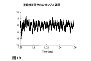
- FIG. 18 is a diagram illustrating a sample section before quasi-instantaneous reverse companding.
- FIG. 19 is a diagram illustrating a sample interval after quasi-instantaneous reverse companding.
- FIG. 20 is a diagram illustrating an output signal after quasi-instantaneous reverse companding.
- FIG. 21 is a diagram illustrating a functional configuration of a signal preprocessing unit according to the second embodiment.
- FIG. 21 is a diagram illustrating a functional configuration of a signal preprocessing unit according to the second embodiment.
- FIG. 22 is a diagram illustrating a functional configuration of a signal post-processing unit according to the second embodiment.
- FIG. 23 is a diagram illustrating a functional configuration of the quasi-instantaneous companding unit according to the second embodiment.
- FIG. 24 is a diagram illustrating a functional configuration of the quasi-instantaneous reverse companding unit according to the second embodiment.
- FIG. 25 is a diagram illustrating a functional configuration of the encoding device according to the third embodiment and the fourth embodiment.
- FIG. 26 is a diagram illustrating a functional configuration of the decoding devices according to the third embodiment and the fourth embodiment.
- FIG. 27 is a diagram illustrating a functional configuration of a signal preprocessing unit according to the third embodiment.
- FIG. 28 is a diagram illustrating a functional configuration of a signal post-processing unit according to the third embodiment.
- FIG. 29 is a diagram illustrating a functional configuration of a signal preprocessing unit according to the fourth embodiment.
- FIG. 30 is a diagram illustrating a functional configuration of a signal post-processing unit according to the fourth embodiment.
- FIG. 31 is a diagram illustrating frequency spectra before and after quasi-instantaneous companding according to the fifth embodiment.
- FIG. 32 is a diagram illustrating a functional configuration of the quasi-instantaneous companding unit according to the sixth embodiment.
- FIG. 33 is a diagram illustrating a functional configuration of the quasi-instantaneous reverse companding section according to the sixth embodiment.
- FIG. 34 is a diagram illustrating frequency spectra before and after quasi-instantaneous companding according to the sixth embodiment.
- FIG. 35 is a diagram illustrating a functional configuration of the sample train deforming device according to the seventh embodiment.
- FIG. 36 is a diagram illustrating a functional configuration of the sample train deforming device according to the seventh embodiment.
- FIG. 37 is a diagram illustrating a functional configuration of the encoding device according to the eighth embodiment.
- FIG. 38 is a diagram illustrating a functional configuration of the decoding device according to the eighth embodiment.
- FIG. 39 is a diagram illustrating a processing procedure of the encoding method according to the eighth embodiment.
- FIG. 40 is a diagram illustrating a processing procedure of the decoding method according to the eighth embodiment.
- FIG. 41 is a diagram illustrating a functional configuration of the encoding device according to the ninth embodiment.
- FIG. 42 is a diagram illustrating a processing procedure of the encoding method according to the ninth embodiment.
- FIG. 43 is a diagram illustrating a functional configuration of an encoding device according to a modification of the ninth embodiment.
- FIG. 44 is a diagram illustrating a processing procedure of the encoding method according to the modified example of the ninth embodiment.
- FIG. 45 is a diagram illustrating a functional configuration of the decoding device according to the ninth embodiment.
- FIG. 46 is a diagram illustrating a processing procedure of the decoding method according to the ninth embodiment.
- FIG. 47 is a diagram illustrating a functional configuration of the signal encoding device according to the tenth embodiment.
- FIG. 48 is a diagram illustrating a functional configuration of the signal decoding apparatus according to the tenth embodiment.
- FIG. 49 is a diagram for explaining a mechanism for improving auditory quality.
- the first embodiment of the present invention includes an encoding device 1 and a decoding device 2.
- the encoding device 1 encodes a sound signal (acoustic signal) such as voice or music input in units of frames to obtain a code and outputs it.
- the code output from the encoding device 10 is input to the decoding device 20.
- the decoding device 20 decodes the input code and outputs an acoustic signal in units of frames.
- the encoding device 1 of the first embodiment includes a signal preprocessing unit 10, a quantization unit 17, a lossless encoding unit 18, and a multiplexing unit 19, as shown in FIG. That is, the signal preprocessing unit 10 is added to the conventional encoding device 91 shown in FIG.
- the decoding device 2 of the first embodiment includes a demultiplexing unit 21, a lossless decoding unit 22, an inverse quantization unit 23, and a signal post-processing unit 25. That is, the signal post-processing unit 25 is added to the conventional decoding device 92 shown in FIG.
- the encoding device 1 and the decoding device 2 are loaded with a special program in a known or dedicated computer having, for example, a central processing unit (CPU), a main storage device (Random access memory, RAM), and the like. It is a special device constructed.
- the encoding device 1 and the decoding device 2 execute each process under the control of the central processing unit.
- the data input to the encoding device 1 and the decoding device 2 and the data obtained in each process are stored in, for example, the main storage device, and the data stored in the main storage device is read out as necessary. It is used for processing.
- at least a part of each processing unit of the encoding device 1 and the decoding device 2 may be configured by hardware such as an integrated circuit.
- the signal preprocessing unit 10 of the encoding device 1 and the signal postprocessing unit 25 of the decoding device 2 perform a “quasi-instantaneous companding” process.
- the quasi-instantaneous companding is a conversion in which sample values within a predetermined interval are grouped together and the sample values are compressed or expanded according to the representative value.
- the signal preprocessing unit 10 includes a quasi-instantaneous companding unit 100.
- the signal post-processing unit 25 includes a quasi-instantaneous reverse companding unit 250 as shown in FIG.
- the quasi-instantaneous companding unit 100 includes a representative value calculating unit 110 and a signal companding unit 120.
- the quasi-instantaneous reverse companding unit 250 includes a companding representative value calculating unit 260 and a signal reverse companding unit 270.
- the encoding device 1 adaptively weights the input signal using quasi-instantaneous companding that does not require auxiliary information as preprocessing to obtain a weighted signal, and the quantum signal similar to the prior art is applied to the weighted signal. And lossless encoding.
- the decoding device 2 receives the code as input and performs lossless decoding and inverse quantization similar to those of the prior art, and reverses the quasi-instantaneous companding of the encoding device 1 using quasi-instantaneous companding that does not require auxiliary information as post-processing. Is applied to the weighted signal.
- the encoding device 1 and the decoding device 2 of the first embodiment can audibly reduce quantization distortion by these processes.
- the acoustic signal X k input to the encoding device 1 is input to the signal preprocessing unit 10.
- One of the predetermined feature amounts is calculated as a representative value and output.
- the representative value may be calculated using, for example, a part of M ′ ( ⁇ M) samples in the section of M samples as follows.
- M ′ is the number of samples used for calculating the representative value
- G m is the number of the sample used for calculating the predetermined representative value.
- the companding function f (x) is an arbitrary function that can define the inverse function f ⁇ 1 (y).
- the companding function f (x) for example, the following generalized logarithmic function can be used.
- ⁇ and ⁇ are predetermined positive numbers.
- companding function f (x) by the conversion after the representative value f (- X m) and the original representative value - with X m, the sample value X k of the audio signal for each section by M samples, the following Thus, it is transformed into a weighted signal Yk .
- first representative value by using the companding function f (x) - converts X m, the weight f corresponding to the function value multiplying the X m and the sample values X k - (- X m) /
- a two-stage calculation is performed, such as transformation into a weighted signal Yk .
- the present invention is not limited to such a calculation method, and any calculation method may be used as long as the calculation can obtain the weighted signal Yk .
- a calculation that performs the calculation of Equation (9) in one step may be performed.
- the companding function that can define the inverse function is not limited to the calculation for a single sample value as shown in Equation (7), and is, for example, a function that outputs a calculation result for each sample with a plurality of samples as arguments. It may be defined as a companding function including an operation that further performs an operation capable of performing an inverse operation on a function that can define an inverse function. For example, in equation (9)
- the quasi-instantaneous companding is expressed by a simple constant multiple that depends only on the representative value in each section.
- a representative value from the weighted signal Y k even decoding device 2 - X m can be estimated by reverse without auxiliary information Drawing can be performed.
- the signal Y k is scalar quantized and a quantized signal is output.
- the quantization unit 17 outputs the quantized signal to the lossless encoding unit 18 and the quantization width used for the quantization to the multiplexing unit 19.
- a predetermined quantization width may be used, or if the code length is too long for the target code length based on the code length of the compression result by the lossless encoding unit 18, quantization is performed.
- the search may be performed by increasing the width and decreasing the quantization width when the code length is too short with respect to the target code length.
- the quantization unit 17 may be operated for each frame having the same number of samples N as the signal preprocessing unit 10, or may be operated for each number of samples different from the signal preprocessing unit 10, for example, every 2N samples. .
- the lossless encoding unit 18 receives the quantized signal output from the quantizing unit 17, assigns a code corresponding to the quantized signal by lossless encoding, and outputs a signal code.
- the lossless encoding unit 18 outputs the signal code to the multiplexing unit 19.
- general entropy encoding may be used, or an existing lossless encoding method such as MPEG-ALS (see Reference 1) or G.711.0 (see Reference 2) is used. Also good.
- the lossless encoding unit 18 may be operated for each frame having the same number of samples N as the signal preprocessing unit 10, or may be operated for each number of samples different from the signal preprocessing unit 10, for example, every 2N samples.
- Good. [Reference 1] T. Liebechen, T. Moriya, N. Harada, Y. Kamamoto, and YA Reznik, “The MPEG-4 Audio Lossless Coding (ALS) standard-technology and applications,” in Proc. AES 119th Convention, Paper # 6589, Oct., 2005. [Reference 2] ITU-T G.711.0, “Lossless compression of G.711 pulse code modulation,” 2009.
- the multiplexing unit 19 receives the quantization width output from the quantization unit 17 and the signal code output from the lossless encoding unit 18, receives a quantization width code that is a code corresponding to the quantization width, and Together with the signal code, it is output as an output code.
- the quantization width code is obtained by encoding the quantization width value.
- a known encoding method may be used as a method of encoding the quantization width value.
- the multiplexing unit 19 may be operated for each frame having the same number of samples N as the signal preprocessing unit 10, or may be operated for each number of samples different from the signal preprocessing unit 10, for example, every 2N samples. .
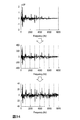
- FIGS. 12 to 15 show specific examples of the process in which the input acoustic signal is deformed by the preprocessing of the encoding method of the first embodiment.
- FIG. 12 shows a signal waveform of the acoustic signal Xk in the time domain. The horizontal axis represents time, and the vertical axis represents amplitude.
- FIG. 12 shows a sound signal X k from 0 seconds to 2 seconds.
- FIG. 13 shows a signal waveform of an acoustic signal in a section of M samples cut out at positions separated by dotted lines in FIG. 12 in order to calculate a representative value. A representative value is calculated from the M samples included in the section of 1.28 seconds to 1.36 seconds shown in FIG.
- FIG. 12 shows a signal waveform of the acoustic signal Xk in the time domain. The horizontal axis represents time, and the vertical axis represents amplitude.
- FIG. 12 shows a sound signal X k from 0 seconds to 2 seconds.
- FIG. 14 is a signal waveform of a weighted signal of a section of M samples after weighting according to the function value of the representative value by the companding function. Compared to FIG. 13, it can be seen that the amplitude value is converted without changing the shape of the waveform.
- FIG. 15 shows the signal waveform of the weighted signal Yk that is finally output from the signal preprocessing unit. Compared with FIG. 12, it can be seen that the whole is drawn.
- the demultiplexing unit 21 receives the code input to the decoding device 2, and outputs the signal code to the lossless decoding unit 22 and the quantization width corresponding to the quantization width code to the inverse quantization unit 23, respectively. .
- the quantization width corresponding to the quantization width code is obtained by decoding the quantization width code.
- a decoding method corresponding to a known encoding method in which the quantization width is encoded may be used.
- the signal post-processing unit 25 operates for each frame having the number of samples N as described below, but the multiplexing unit 19 may be operated for each frame having the same number of samples N as the signal post-processing unit 25. The operation may be performed every number of samples different from the post-processing unit 25, for example, every 2N samples.
- the lossless decoding unit 22 receives the signal code output from the demultiplexing unit 21, performs lossless decoding corresponding to the processing of the lossless encoding unit 18, and reverses the signal corresponding to the signal code as a decoded quantized signal.
- the data is output to the quantization unit 23.
- the lossless decoding unit 22 may be operated for each frame having the same number of samples N as the signal post-processing unit 25, or may be operated for each number of samples different from the signal post-processing unit 25, for example, every 2N samples. .
- the inverse quantization unit 23 receives the decoded quantized signal output from the lossless decoding unit 22 and the quantization width output from the demultiplexing unit 21, and corresponds to the quantization width, for example, as in the prior art.
- the value to be multiplied by each sample value of the decoded quantized signal is multiplied for each sample to obtain a dequantized signal.
- the inverse quantization unit 23 may be operated for each frame having the same number of samples N as the signal post-processing unit 25, or may be operated for each number of samples different from the signal post-processing unit 25, for example, every 2N samples. Good.
- Companding representative value - calculation method of Y m are used the same as the representative value calculation unit 110 of the encoding apparatus 1 corresponding to the decoding apparatus 2.
- the companding representative value calculated here (the companding representative value calculating unit 260) is quantized by the encoding device 1.
- the representative value calculated by the representative value calculation unit 110 of the encoding device 1 is equal to the value obtained by converting with the companding function, and there is quantization distortion in the encoding device 1.
- the value obtained by converting the representative value calculated by the representative value calculation unit 110 of the encoding device 1 by the companding function is almost the same value. Therefore, the signal representative companding unit 270 in the latter stage can invert the companding representative value using the inverse function of the companding function to estimate the original representative value, and the reverse companding can be performed without auxiliary information. It can be carried out.
- FIG. 17 to 20 show specific examples of the process in which the decoding weighted signal is transformed by the post-processing of the decoding method of the first embodiment.
- FIG. 17 shows a signal waveform of the decoding weighted signal ⁇ Yk obtained by the decoding method. The horizontal axis represents time, and the vertical axis represents amplitude. In the example of FIG. 17, the decoding weighted signal ⁇ Y k from 0 second to 2 seconds is shown.
- FIG. 18 is a signal waveform of a decoding weighted signal in a section of M samples cut out at positions separated by dotted lines in FIG. 17 in order to calculate a companding representative value. A companding representative value is calculated from the M samples included in the section of 1.28 seconds to 1.36 seconds shown in FIG.
- FIG. 19 shows the signal waveform of the output signal in the section of M samples after weighting according to the function value of the companding representative value by the inverse function of the companding function. Compared to FIG. 18, it can be seen that the amplitude value is converted without changing the shape of the waveform.
- FIG. 20 shows the signal waveform of the output signal ⁇ X k that is finally output from the signal post-processing section. Compared with FIG. 17, it turns out that it is reverse-drawn as a whole.
- the signal pre-processing unit 10 and the signal post-processing unit 25 of the first embodiment perform the quasi-instantaneous companding process with the time domain signal, but the signal weighting by the quasi-instantaneous companding is performed even in the frequency domain. In particular, quantization distortion can be reduced.
- the signal preprocessing unit and the signal postprocessing unit are processed in the frequency domain.
- the encoding device 3 of the second embodiment includes a signal preprocessing unit 11, a quantization unit 17, a lossless encoding unit 18, and a multiplexing unit 19, as shown in FIG. That is, the processing of the signal preprocessing unit is different from that of the encoding device 1 of the first embodiment.
- the decoding device 4 according to the second embodiment includes a demultiplexing unit 21, a lossless decoding unit 22, an inverse quantization unit 23, and a signal post-processing unit 26. That is, the signal post-processing unit is different from the decoding device 2 of the first embodiment.
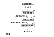
- the signal preprocessing unit 11 includes a frequency conversion unit 130, a quasi-instantaneous companding unit 101, and a frequency inverse conversion unit 140.
- the signal post-processing unit 26 includes a frequency conversion unit 280, a quasi-instantaneous reverse companding unit 251, and a frequency reverse conversion unit 290, as shown in FIG.
- the quasi-instantaneous companding unit 101 includes a representative value calculating unit 111 and a signal companding unit 121 as shown in FIG.
- the quasi-instantaneous reverse companding unit 251 includes a companding representative value calculating unit 261 and a signal reverse companding unit 271 as shown in FIG.
- the quasi-instantaneous companding part 101 and the quasi-instantaneous counter-compressing part 251 are different from the quasi-instantaneous companding part 100 and the quasi-instantaneous inverse companding part 250 of the first embodiment in that the input / output is a frequency spectrum. .
- the acoustic signal x n input to the encoding device 3 is input to the signal preprocessing unit 11.
- ⁇ Third embodiment> The signal preprocessing unit 11 and the signal postprocessing unit 26 of the second embodiment performed quasi-instantaneous companding in the frequency domain, and then returned to the time domain to perform encoding and decoding processing.
- encoding and decoding processes are performed in the frequency domain without returning to the time domain.
- the encoding device 5 of the third embodiment includes a signal preprocessing unit 12, a quantization unit 17, a lossless encoding unit 18, and a multiplexing unit 19. That is, the processing of the signal preprocessing unit is different from that of the encoding device 3 of the second embodiment.
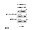
- the decoding device 6 according to the third embodiment includes a demultiplexing unit 21, a lossless decoding unit 22, an inverse quantization unit 23, and a signal post-processing unit 27. That is, the signal post-processing unit is different from the decoding device 4 of the second embodiment.
- the signal preprocessing unit 12 includes a frequency conversion unit 130 and a quasi-instantaneous companding unit 101 as shown in FIG. That is, it differs from the signal preprocessing unit 11 of the second embodiment in that the frequency inverse transform unit 140 is not included and a weighted frequency spectrum is output.
- the signal post-processing unit 27 includes a quasi-instantaneous reverse companding unit 251 and a frequency inverse converting unit 290. That is, it differs from the signal post-processing unit 26 of the second embodiment in that the frequency conversion unit 280 is not included and a decoding weighted frequency spectrum is input.
- the quantization unit 17, the lossless encoding unit 18, the lossless decoding unit 22, and the inverse quantization unit 23 are the same as the quantization unit 17, the lossless encoding unit 18, the lossless decoding unit 22, and the inverse quantization unit 23 of the second embodiment. Although the same processing is performed, it is different from the second embodiment in that a frequency spectrum is handled instead of the time domain signal.
- the processing of the frequency conversion unit 130 and the quasi-instantaneous companding unit 101 is the same as that in the second embodiment described above.
- the lossless decoding unit 22 receives the signal code output from the demultiplexing unit 21, performs lossless decoding corresponding to the processing of the lossless encoding unit 18, and dequantizes the frequency spectrum corresponding to the signal code as a decoded quantized frequency spectrum. To the unit 23.
- the inverse quantization unit 23 receives the decoded quantized frequency spectrum output from the lossless decoding unit 22 and the quantization width output from the demultiplexing unit 21, and, for example, in the same manner as in the prior art, a value corresponding to the quantization width and Each sample value of the decoded quantized frequency spectrum is multiplied for each sample to obtain a dequantized signal.
- the processes of the quasi-instantaneous reverse companding unit 251 and the frequency reverse converting unit 290 are the same as those in the second embodiment described above.
- the signal preprocessing unit 10 and the signal postprocessing unit 25 of the first embodiment performed the quasi-instantaneous companding process on the time domain signal, and then performed the encoding and decoding processes in the time domain.
- the quasi-instantaneous companding process is performed with the time domain signal, and then the signal is converted into the frequency domain to be encoded and decoded.
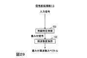
- the encoding device 7 according to the fourth embodiment includes a signal preprocessing unit 13, a quantization unit 17, a lossless encoding unit 18, and a multiplexing unit 19, as shown in FIG. That is, the processing of the signal preprocessing unit is different from that of the encoding device 1 of the first embodiment.
- the decoding device 8 of the fourth embodiment includes a demultiplexing unit 21, a lossless decoding unit 22, an inverse quantization unit 23, and a signal post-processing unit 28. That is, the signal post-processing unit is different from the decoding device 2 of the first embodiment.
- the signal pre-processing unit 13 includes a quasi-instantaneous companding unit 100 and a frequency converting unit 130 as shown in FIG. That is, as compared with the signal preprocessing unit 10 of the first embodiment, the frequency converter 130 is connected to the subsequent stage of the quasi-instantaneous companding unit 100 and a weighted frequency spectrum is output.
- the signal post-processing unit 28 includes a frequency reverse conversion unit 290 and a quasi instantaneous reverse companding unit 250, as shown in FIG. That is, the difference from the signal post-processing unit 25 of the first embodiment is that the frequency inverse transform unit 290 is connected to the preceding stage of the quasi-instantaneous reverse companding unit 250 and the decoded weighted frequency spectrum is input.
- the quantization unit 17, the lossless encoding unit 18, the lossless decoding unit 22, and the inverse quantization unit 23 are the same as the quantization unit 17, the lossless encoding unit 18, the lossless decoding unit 22, and the inverse quantization unit 23 of the first embodiment. Although the same processing is performed, it is different from the first embodiment in that a frequency spectrum is handled instead of the time domain signal.
- the acoustic signal x n input to the encoding device 7 is input to the signal preprocessing unit 13.
- the processing of the frequency conversion unit 130 is the same as that in the second embodiment described above.
- the lossless decoding unit 22 receives the signal code output from the demultiplexing unit 21, performs lossless decoding corresponding to the processing of the lossless encoding unit 18, and dequantizes the frequency spectrum corresponding to the signal code as a decoded quantized frequency spectrum. To the unit 23.
- the inverse quantization unit 23 receives the decoded quantized frequency spectrum output from the lossless decoding unit 22 and the quantization width output from the demultiplexing unit 21, and, for example, in the same manner as in the prior art, a value corresponding to the quantization width and Each sample value of the decoded quantized frequency spectrum is multiplied for each sample to obtain a dequantized signal.
- the processing of the frequency inverse transform unit 290 is the same as that in the second embodiment described above.
- ⁇ Points from the first embodiment to the fourth embodiment> In the first embodiment, a configuration has been described in which preprocessing and postprocessing are performed in the time domain, and encoding processing and decoding processing are performed in the time domain. In the second embodiment, a configuration has been described in which preprocessing and postprocessing are performed in the frequency domain, and encoding processing and decoding processing are performed in the time domain. In the third embodiment, a configuration has been described in which preprocessing and postprocessing are performed in the frequency domain, and encoding processing and decoding processing are performed in the frequency domain. In the fourth embodiment, a configuration has been described in which preprocessing and postprocessing are performed in the time domain, and encoding processing and decoding processing are performed in the frequency domain.
- the pre-processing and post-processing, and the encoding processing and decoding processing can be performed in any combination of frequency domain and time domain.
- the pre-processing and post-processing of the present invention are applicable to both frequency domain encoding processing and decoding processing and time domain encoding processing and decoding processing.
- a plurality of sample sections for performing the quasi-instantaneous companding process can be inversely transformed without using auxiliary information, regardless of how long the section is determined in advance.
- auditory quality is taken into consideration, it is possible to more appropriately determine a plurality of sample intervals for performing the quasi-instantaneous companding process.
- L intervals be [K 0 K 1 ], [K 1 K 2 ],..., [K L-1 K L ]
- K m-1 K m ] represents that the (K m-1 +1) -th sample to the K m- th sample in the frame are defined as the m-th interval.
- the processing interval can be set finer as the frequency is lower, and the processing interval coarser as the frequency is higher.
- Companding function f (x) by the conversion after the representative value f (- X m) and the original representative value - with X m, the sample value X of the frequency spectrum for each the L section including a sample number a predetermined k is transformed into a weighted frequency spectrum Y k as follows.
- the decoding device of the fifth embodiment is obtained by changing the processes of the companding representative value calculation unit 261 and the signal reverse companding unit 271 in the decoding device 4 of the second embodiment as follows.
- FIG. 31 shows a specific example of a frequency spectrum when signal companding is performed by dividing the section more finely as the low frequency and coarser as the high frequency by the preprocessing of the encoding method of the fifth embodiment.
- the frequency band of 0 to 2000 Hz is divided into 5 sections, and for example, the frequency band of 5000 Hz to 8000 Hz is all included in one section, and is finer as the low frequency and coarser as the high frequency.
- the processing section is set as follows.
- ⁇ Sixth embodiment> When a signal that has no undulations in the spectrum and shows a uniformly large value is subjected to quasi-instantaneous companding by finely dividing the section, the spectrum value in the frame is uniformly reduced. In other words, the quantization performance may be adversely affected.
- a quasi-instantaneous companding process is hierarchically used as a countermeasure. For example, quasi-instantaneous companding is first performed in a rough section in the frame, and the value of a section with high energy is increased using, for example, an inverse function of the companding function. Thereafter, quasi-instantaneous companding is performed in a finer section. In the inverse transformation, first, quasi-instantaneous reverse companding is performed in a fine section, and then, the original frequency spectrum is obtained by performing quasi-instantaneous reverse companding in a rough section.
- the encoding device of the sixth embodiment is obtained by changing the processing of the quasi-instantaneous companding unit 101 in the encoding device 3 of the second embodiment as follows.
- the configuration of the sixth embodiment can be applied to the second embodiment, and can be applied to all the embodiments from the first embodiment to the fifth embodiment.
- the quasi-instantaneous companding unit 102 of the sixth embodiment includes a representative value calculating unit 112 and a signal companding unit 122, and the output of the signal companding unit 122 is input to the representative value calculating unit 112. Configured to be
- the sample number M of the section for which the representative value calculation unit 112 obtains the representative value may be configured to be different every time it is repeated.
- Companding function f (x) by the conversion after the representative value f (- X m) and the original representative value - with X m, the sample values ⁇ X k of the frequency spectrum for each section of the M samples, as follows It is transformed into a weighted frequency spectrum Yk .
- the companding function f (x) used by the signal companding unit 122 may be configured to use a different one each time it is repeated. For example, the inverse function f ⁇ 1 (x) of the companding function f (x) is used for the first time, and the companding function f (x) is used for the second time.
- the decoding device of the sixth embodiment is obtained by changing the processing of the quasi-instantaneous reverse companding unit 251 in the decoding device 4 of the second embodiment as follows.
- the configuration of the sixth embodiment can be applied to the second embodiment, and can be applied to all the embodiments from the first embodiment to the fifth embodiment.
- the quasi-instantaneous reverse companding unit 252 of the sixth embodiment includes a companding representative value calculating unit 262 and a signal reverse companding unit 272, and the output of the signal reverse companding unit 272 is a companding representative. It is configured to be input to the value calculation unit 262.
- Companding representative value - calculation method of Y m are used the same as the representative value calculation unit 112 of the coding apparatus corresponding to the decoding apparatus.
- the number of samples M in the section for which the companding representative value calculation unit 262 obtains the companding representative value corresponds to the number of samples M used by the representative value calculating unit 112 of the encoding device corresponding to the decoding device each time it is repeated.
- Companding function f companding representative value was converted by the inverse function f -1 (y) of (x) f -1 (- Y m) and the original companding representative values - with Y m, predetermined M samples of the section Every time, the sample value ⁇ Y k of the decoding weighted frequency spectrum is transformed into the sample value of the decoding frequency spectrum ⁇ X k as follows.
- the inverse function f ⁇ 1 (y) of the companding function f (x) used by the signal inverse companding unit 272 is an inverse function corresponding to the companding function f (x) used by the signal companding unit 122 every time it is repeated. It is configured to use.
- the companding function f (x) is used as the inverse function of the inverse function f ⁇ 1 (x) of the companding function f (x) at the first time, and the inverse function with respect to the companding function f (x) is performed the second time.
- the inverse function f ⁇ 1 (x) of the companding function f (x) is used as
- FIG. 34 shows a specific example of a frequency spectrum when the representative value calculation and the signal companding process are repeated a plurality of times by the preprocessing of the encoding method of the sixth embodiment.
- the quasi-instantaneous reverse companding unit 251 included in the unit 250 and the decoding devices 4 and 6 can also be configured as an independent sample train deforming device.
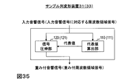
- This sample sequence transformation device 33 is a weighted frequency domain signal for input to an encoding device for encoding a weighted frequency domain signal obtained by transforming a frequency domain signal corresponding to an input acoustic signal, or an input acoustic signal.
- a weighted frequency domain corresponding to a weighted time domain signal for input to an encoding device for encoding a weighted time domain signal corresponding to a weighted frequency domain signal obtained by modifying a frequency domain signal corresponding to the signal For example, as shown in FIG.
- the sample train deforming apparatus for obtaining a signal includes a representative value calculating unit 111 and a signal companding unit 121.
- the representative value calculation unit 111 calculates, for each predetermined time interval, from the sample sequence of the frequency domain signal corresponding to the input acoustic signal, for each frequency interval with a plurality of samples less than the number of frequency samples in the frequency domain sample sequence, The representative value of the frequency section is calculated from the sample values of the included samples.
- the signal companding unit 121 includes, for each predetermined time interval, a weight corresponding to the function value of the representative value by the companding function that can define an inverse function, and each sample corresponding to the representative value in the frequency domain sample sequence.
- the multiplied frequency domain sample sequence is obtained as a sample sequence of the weighted frequency domain signal.
- This sample sequence transformation device 34 is a weighted frequency domain signal obtained by a decoding device that obtains a weighted frequency domain signal corresponding to a frequency domain signal corresponding to a decoded acoustic signal, or a frequency domain corresponding to a decoded acoustic signal.
- the companding representative value calculation unit 261 performs, for each predetermined time interval, from the sample sequence of the weighted frequency domain signal, the frequency segment for each frequency segment by a plurality of samples smaller than the number of frequency samples in the sample sequence of the weighted frequency domain signal.
- the representative value of the frequency section is calculated from the sample values of the samples included in.
- the signal reverse companding unit 271 corresponds to a weight corresponding to a function value of a representative value by a companding function capable of defining an inverse function for each predetermined time interval, and the representative value in the sample sequence of the weighted frequency domain signal.
- a frequency domain sample sequence obtained by multiplying each sample is obtained as a sample sequence of the frequency domain signal corresponding to the decoded acoustic signal.
- This sample string transformation device 31 is a weighted acoustic signal for input to an encoding device that encodes a weighted acoustic signal obtained by transforming an input acoustic signal, or a weight obtained by transforming an input acoustic signal.
- a sample-sequence modification device that obtains a weighted acoustic signal corresponding to a weighted frequency domain signal for input to an encoding device that encodes a weighted frequency domain signal corresponding to the attached acoustic signal, for example, FIG.
- the representative value calculation unit 110 and the signal companding unit 120 are included.
- the representative value calculation unit 110 is included in the time interval for each predetermined time interval from a sample sequence of the input acoustic signal in the time domain to a time interval of a plurality of samples smaller than the number of samples in the sample sequence of the input acoustic signal.
- a representative value of the time interval is calculated from the sample value of the sample.
- the signal companding unit 120 has a weight corresponding to a function value of a representative value by a companding function capable of defining an inverse function for each predetermined time interval, each sample corresponding to the representative value in the sample sequence of the input acoustic signal, and , And a time-domain sample sequence obtained by multiplying and is obtained as a sample sequence of the weighted acoustic signal.
- This sample sequence transformation device 32 obtains a time-domain weighted acoustic signal corresponding to the decoded acoustic signal by decoding.
- FIG. 36 shows a sample train deforming device that obtains a decoded acoustic signal from a weighted acoustic signal in a time domain corresponding to a weighted acoustic signal in a frequency domain obtained by a decoding device that obtains an attached acoustic signal by decoding.
- a companding representative value calculation unit 260 and a signal reverse companding unit 270 are included.
- the companding representative value calculation unit 260 performs, for each predetermined time interval, from the sample sequence of the weighted acoustic signal in the time domain, for each time interval by a plurality of samples less than the number of samples in the sample sequence of the weighted acoustic signal.
- a representative value of the time interval is calculated from the sample values of the samples included in the interval.
- the signal reverse companding unit 270 corresponds to the weight corresponding to the function value of the representative value by the companding function capable of defining the inverse function for each predetermined time interval, and the representative value in the sample sequence of the weighted frequency domain signal.
- a frequency domain sample sequence obtained by multiplying each sample is obtained as a sample sequence of the frequency domain signal corresponding to the decoded acoustic signal.
- the sample string transformation devices 33 and 34 are set so that the number of samples included in the section corresponding to the low frequency is small as the section of the plurality of samples is in the section corresponding to the low frequency, and the number of samples included in the section corresponding to the high frequency is increased.
- the sample row deforming device 35 can be configured.
- the sample string deforming devices 31 to 35 calculate a representative value for each section of a plurality of samples of the input acoustic signal, and multiply each sample of the sample string by a weight corresponding to the calculated function value of the representative value.
- the sample train deforming device 36 can be configured to be repeatedly executed a predetermined number of times.
- the pre-processing by quasi-instantaneous companding and the post-processing by quasi-instantaneous inverse companding have the property of reducing auditory distortion instead of increasing numerical errors such as the square error of the waveform of the decoded signal.
- the pre-processing and the post-processing are used instead of the pre-processing and the post-processing. It is more convenient to compress or process the decoded signal again, aiming to reduce the numerical error of the waveform of the simple decoded signal without using post-processing.
- whether or not to perform pre-processing and post-processing of the signal by quasi-instantaneous companding and quasi-instantaneous reverse companding depends on the quantization width of the frequency domain signal corresponding to the input acoustic signal or the input acoustic signal. Select for each frame based on the value of.
- the eighth embodiment can be applied to the first embodiment, the second embodiment, the fifth embodiment, and the sixth embodiment applied to these embodiments.
- the presence or absence of signal preprocessing is selected based on the value of the quantization width of the input acoustic signal or the frequency domain signal corresponding to the input acoustic signal.
- the decoding device by selecting the presence or absence of post-processing based on the quantization width obtained by decoding, only the frame pre-processed by the encoding device corresponds to the pre-processing performed by the encoding device.
- Post-processing can be performed. That is, the decoding apparatus can perform a decoding process corresponding to the encoding process performed by the encoding apparatus.
- the encoding device 41 according to the eighth embodiment includes a signal preprocessing unit 51, a quantization unit 52, a lossless encoding unit 18, and a multiplexing unit 19. Since the process performed by the quantization unit 52 is complicated in the encoding device 41 of the eighth embodiment, the processing procedure of the encoding method executed by the encoding apparatus 41 of the eighth embodiment is described with reference to FIG. explain.
- the acoustic signal X k input to the encoding device 41 is first input to the quantization unit 52.
- the quantizing unit 52 for example, as in the prior art, to obtain an integer value as a quantized signal by dividing a sound signal X k with a value corresponding to the quantization width.
- the quantization width is increased when the code length is too long for the target code length, and the code length is set to the target code length. If the code length is too short, the search is performed such that the quantization width is reduced. That is, the quantization width is a value obtained by searching and is a value estimated to be optimal.
- step S52 the quantization unit 52 converts the quantized signal into a lossless encoding unit for a frame in which the quantization width used in the quantization in step S51 is smaller than a predetermined threshold value or less than the predetermined threshold value. 18, the quantization width used for quantization is output to the multiplexing unit 19, and for the other frames, information for operating the signal preprocessing unit of the frame is output to the signal preprocessing unit 51. To do.
- step S14 the quantization unit 52 divides the weighted signal Yk by a value corresponding to the quantization width to obtain an integer value as a quantized signal, as in the prior art. For example, based on the code length of the compression result by the lossless encoding unit 18, the quantization width is increased when the code length is too long for the target code length, and the code length is set to the target code length. If the code length is too short, the search is performed such that the quantization width is reduced. That is, the quantization width is a value obtained by searching and is a value estimated to be optimal.
- the quantization width obtained by the search in step S14 is larger than the quantization width obtained by the search in step S51, and is larger than the threshold value in step S52.
- the lower limit value of the quantization width obtained by the search in step S14 is set in step S52. What is necessary is just to set it as the value more than the threshold value in or larger than a threshold value.
- the quantization unit 52 outputs the quantized signal to the lossless encoding unit 18 and the quantization width used for the quantization to the multiplexing unit 19.
- Step S15 performed by the lossless encoding unit 18 and step S16 performed by the multiplexing unit 19 are the same as those in the first embodiment.
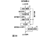
- the decoding device 42 includes a demultiplexing unit 61, a lossless decoding unit 22, an inverse quantization unit 23, a determination unit 62, and a signal post-processing unit 63.
- a processing procedure of the decoding method executed by the decoding device 42 of the eighth embodiment will be described.
- step S ⁇ b> 21 the demultiplexing unit 61 receives the code input to the decoding device 42, converts the signal code to the lossless decoding unit 22, and sets the quantization width corresponding to the quantization width code to the inverse quantization unit 23 and the determination unit 62. Respectively.
- the process of obtaining the quantization width by decoding is the same as that of the demultiplexing unit 21.
- Step S22 performed by the lossless decoding unit 22 and step S23 performed by the inverse quantization unit 23 are the same as in the first embodiment.
- the pre-processing and post-processing of signals tend to be necessary as the quantization accuracy of the input acoustic signal and the frequency domain signal corresponding to the input acoustic signal is coarser, and as the quantization accuracy is finer, it becomes unnecessary.
- By adaptively changing the degree of quasi-instantaneous companding for each frame it is possible to apply weighting more in accordance with the signal.
- the encoding device of the ninth embodiment determines the degree of quasi-instantaneous companding in the signal preprocessing for each frame based on the input acoustic signal and the value of the quantization width of the frequency domain signal corresponding to the input acoustic signal. Select and send a coefficient specifying the degree of the selected quasi-instantaneous companding to the decoding device.
- the decoding apparatus according to the ninth embodiment selects, for each frame, the degree of quasi-instantaneous reverse companding in the post-processing of the signal based on the coefficient specifying the degree of quasi-instantaneous companding sent from the encoding apparatus.
- the decoding device also determines the degree of quasi-instantaneous companding used for signal preprocessing in the encoding device based on a coefficient that specifies the degree of quasi-instantaneous companding, and the encoding device performs the processing.
- Post-processing corresponding to the pre-processing can be performed. That is, the decoding apparatus can perform a decoding process corresponding to the encoding process performed by the encoding apparatus.
- ⁇ in Equation (7) is a coefficient that specifies the degree of quasi-instantaneous companding.
- ⁇ which is a coefficient that specifies the degree of quasi-instantaneous companding, is also referred to as companding coefficient.
- the ninth embodiment can be applied to all the embodiments from the first embodiment to the sixth embodiment.
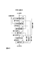
- the encoding device 43 of the ninth embodiment includes a quantization width calculation unit 53, a companding coefficient selection unit 54, a signal preprocessing unit 55, a quantization unit 17, a lossless encoding unit 18, and Multiplexer 56 is included.
- the processing procedure of the encoding method executed by the encoding device 43 of the ninth embodiment will be described.
- the acoustic signal X k input to the encoding device 43 is first input to the quantization width calculation unit 53.
- the quantization width calculation unit 53 determines the quantization width based on, for example, the code length of the compression result by lossless encoding, and if the code length is too long for the target code length.
- the search is performed by increasing the quantization width and decreasing the quantization width when the code length is too short with respect to the target code length. That is, the quantization width is a value obtained by searching and is a value estimated to be optimal.
- the estimated value of the calculated quantization width may be output to the companding coefficient selection unit 54 as the quantization width.
- the companding coefficient selector 54 receives the quantized width output from the quantized width calculator 53 for each frame, and stores a plurality of companding coefficients ⁇ stored in advance in the companding coefficient selector 54.
- One candidate value corresponding to the quantization width value is selected as the companding coefficient ⁇ from the candidate values.
- a companding function is used so that the power of the weighted acoustic signal after companding or the weighted frequency domain signal sample sequence corresponding to the input acoustic signal becomes flat.
- the input acoustic signal and the weighted acoustic signal before and after companding, or between the sample sequence of the frequency domain signal corresponding to the input acoustic signal and the sample sequence of the weighted frequency domain signal A companding function is selected so as to specify a companding function that makes the difference smaller.
- the companding coefficient selection unit 54 outputs the companding coefficient ⁇ obtained by the selection to the signal preprocessing unit 55 and the multiplexing unit 56.
- Step S14 performed by the quantization unit 17 and step S15 performed by the lossless encoding unit 18 are the same as those in the first embodiment.
- the multiplexing unit 56 receives the quantization width output from the quantization unit 17, the signal code output from the lossless encoding unit 18, and the companding coefficient output from the companding coefficient selection unit 54. Then, a quantization width code that is a code corresponding to the quantization width, a companding coefficient code that is a code corresponding to the companding coefficient, and a signal code are output together as an output code.
- the quantization width code is obtained by encoding the quantization width value.
- a known encoding method may be used as a method of encoding method may be used.
- the companding coefficient sign is obtained by encoding the value of the companding coefficient.
- the multiplexing unit 56 may be operated for each frame having the same number of samples N as the signal preprocessing unit 55, or may be operated for each number of samples different from the signal preprocessing unit 55, for example, every 2N samples. .
- an encoding device 45 includes an input signal quantization unit 57, a companding coefficient selection unit 54, a signal preprocessing unit 55, a quantization unit 17, and a lossless encoding unit. 18 and a multiplexing unit 56.
- FIG. 44 the processing procedure of the encoding method executed by the encoding device 45 according to the modification of the ninth embodiment will be described.
- the acoustic signal X k input to the encoding device 45 is first input to the input signal quantization unit 57.
- the input signal quantization unit 57 for example, as in the prior art, to obtain an integer value as a quantized signal by dividing a sound signal X k with a value corresponding to the quantization width.
- the method for obtaining the quantization width is the same as that of the quantization width calculation unit 53 of the encoding device 43 of the ninth embodiment.
- the input signal quantization unit 57 outputs the obtained quantization width to the companding coefficient selection unit 54 and the multiplexing unit 56, and outputs the quantized signal to the lossless encoding unit 18.
- the output of the quantization width to the multiplexing unit 56 and the output of the quantized signal to the lossless encoding unit 18 are controlled by the companding coefficient selection unit 54.
- Step S54 performed by the companding coefficient selector 54 is the same as that of the encoding device 43 of the ninth embodiment.
- the companding coefficient selecting unit 54 outputs the companding coefficient ⁇ obtained by the selection to the signal preprocessing unit 55, and the companding coefficient ⁇ is 1. In this case, control is performed so that the quantized signal obtained by the input signal quantizing unit 57 is input to the lossless encoding unit 18 and the quantization width obtained by the input signal quantizing unit 57 is input to the multiplexing unit 56. In addition, the companding coefficient selection unit 54 outputs the companding coefficient ⁇ to the multiplexing unit 58.
- the signal pre-processing unit 55 receives the companding coefficient ⁇ output from the companding coefficient selecting unit 54.
- Step S14 performed by the quantization unit 17 is the same as that of the encoding device 43 of the ninth embodiment. However, step S14 is performed only when the companding coefficient ⁇ is not 1, that is, when a value other than quasi-instantaneous companding is designated.
- Step S15 performed by the lossless encoding unit 18 and step S55 performed by the multiplexing unit 56 are the same as those of the encoding device 43 of the ninth embodiment.
- the decoding device 44 of the ninth embodiment includes a demultiplexing unit 64, a lossless decoding unit 22, an inverse quantization unit 23, and a signal post-processing unit 65.
- a processing procedure of a decoding method executed by the decoding device 44 of the ninth embodiment will be described.
- step S62 the demultiplexing unit 64 receives the code input to the decoding device 44, receives the signal code to the lossless decoding unit 22, and the companding coefficient ⁇ corresponding to the companding coefficient code to the signal post-processing unit 65.
- the quantization width corresponding to the quantization width code is output to the inverse quantization unit 23, respectively.
- Step S22 performed by the lossless decoding unit 22 and step S23 performed by the inverse quantization unit 23 are the same as in the first embodiment.
- the decoded weighted signal ⁇ Y k and the output signal ⁇ X k are the same. Therefore, the first embodiment using the companding coefficient ⁇ for the decoding weighted signal ⁇ Y k only when the companding coefficient ⁇ is not 1, that is, when a value other than quasi-instantaneous companding is designated.
- the encoding device and the decoding device of the eighth embodiment can be configured as a signal encoding device and a signal decoding device using the sample string transformation device described in the seventh embodiment.
- the signal encoding device using the sample string transformation device of the seventh embodiment is configured as follows.
- the signal encoding device 71 includes the sample string deforming device 31 or 33 of the seventh embodiment, and an encoding device 50 that encodes a signal to be encoded to obtain a signal code.
- the encoding device 50 performs, for example, processing corresponding to other than the signal preprocessing unit 51 of the encoding device 41 of the eighth embodiment, and the sample string transformation device 31 or 33 is, for example, the encoding device of the eighth embodiment.
- the processing corresponding to the 41 signal preprocessing unit 51 is performed.
- the signal encoding device 71 is obtained by obtaining the quantization width for encoding the input acoustic signal or the frequency domain signal corresponding to the input acoustic signal with the target code length by the encoding device 50 for each predetermined time interval.
- the input acoustic signal or a frequency domain signal corresponding to the input acoustic signal is encoded by the encoding device 50 as an encoding target signal
- the input acoustic signal or the frequency domain signal corresponding to the input acoustic signal is input to the sample train deforming device 31 or 33, and the weighted acoustic signal or the weighted frequency obtained by the sample train transforming device 31 or 33 is obtained.
- the sample sequence of the region signal is encoded by the encoding device 50 as an encoding target signal.
- the signal decoding apparatus using the sample string transformation apparatus of the seventh embodiment is configured as follows.
- the signal decoding device 72 includes a sample string transformation device 32 or 34 according to the seventh embodiment, and a decoding device 60 that decodes a signal code to obtain a decoded signal.
- the decoding device 60 performs a process corresponding to, for example, other than the signal post-processing unit 63 of the decoding device 42 according to the eighth embodiment, and the sample string transformation device 32 or 34 performs, for example, a signal of the decoding device 42 according to the eighth embodiment. Processing corresponding to the post-processing unit 63 is performed.
- the signal decoding device 72 decodes the quantization width code and obtains the quantization width by the decoding device 60 every predetermined time interval, and the obtained quantization width is smaller than the predetermined threshold value or less than the predetermined threshold value. For a certain time interval, a signal obtained by decoding the signal code by the decoding device 60 is obtained as a decoded acoustic signal or a frequency domain signal corresponding to the decoded acoustic signal, and for other time intervals, the decoding device 60 obtains the signal.
- the received signal is input to the sample train deforming device 32 or 34 to obtain a decoded acoustic signal or a frequency domain signal corresponding to the decoded acoustic signal.
- the concept of the ninth embodiment can be applied to the sample train deforming device 31 or 33 described in the seventh embodiment to configure as the sample train deforming device 37.
- the sample string deforming device 37 uses the sample string deforming device 31 or 33 to obtain a companding function corresponding to the companding coefficient selected by the quantization width calculating unit and the companding coefficient selecting unit 54 described in the ninth embodiment. It is comprised so that the companding function selection part which performs the process to select may be further included.
- the quantization width calculation unit obtains a quantization width for encoding the input acoustic signal or the frequency domain signal corresponding to the input acoustic signal with the target code length for each predetermined time interval.
- the companding function selector selects the input acoustic signal and the weighted acoustic signal or the sample sequence of the frequency domain signal corresponding to the input acoustic signal and the weight as the quantization width is smaller as the companding function for each predetermined time interval.
- the companding function is selected such that the closer the sample sequence of the weighted frequency domain signal is, or / and the greater the quantization width, the flatter the power of the sample sequence of the weighted acoustic signal or weighted frequency domain signal.
- the quasi-instantaneous companding can perform transformations having the following two properties without adding auxiliary information. 1. In the frame, a signal value or a frequency spectrum value of the signal is given a relatively small weight and a small value is given a relatively large weight. 2. In the frame, a relatively small weight is applied to the vicinity of the peak of the signal or the frequency spectrum of the signal in the same manner as the peak.
- a relatively small weight is applied to the vicinity of the peak of the signal or the frequency spectrum of the signal in the same manner as the peak.
- FIG. 49A shows the frequency spectrum of the quantization error when the original signal is quantized at regular intervals in the time domain. In this case, since the quantization error of a flat spectrum occurs and it is annoying, the auditory quality is deteriorated.
- FIG. 49B shows the frequency spectrum of the quantization error when the companded original signal obtained by companding the original signal is quantized at equal intervals in the time domain. It can be seen that the companding signal and the quantization error have the same flat spectrum.
- FIG. 49C shows a frequency spectrum of a quantization error in the case of reverse companding FIG. In this case, since it becomes a quantization error along the inclination of the spectrum of the original signal, it becomes difficult to hear noise and the auditory quality is improved.
- a representative value is obtained for each sample within a predetermined interval, and based on that representative value
- a general representative value is how to determine - the value of X m is not Motomara, performing the inverse transform I can't.
- the function that determines the representative value is not Motomara, performing the inverse transform I can't.
- the original representative value can also be obtained by the decoding apparatus. Inverse transformation based on this value
- the original sample value can be obtained without using auxiliary information.
- the companded Y k is quantized in the middle, and if an error occurs, the original representative value cannot be obtained correctly, but by performing the same process as above on the quantized Y k , the representative value - estimated value of X m can be calculated, it is possible to perform inverse transform on the basis of its value.
- weighting suitable for auditory characteristics can be performed according to the audio-acoustic signal without adding auxiliary information, and the efficiency of lossy compression coding can be increased. it can.
- the configuration of the fifth embodiment by setting the section used for the quasi-instantaneous companding to be fine at the low frequency and coarse at the high frequency, weighting more suitable for the auditory characteristics can be realized.
- the configuration of the sixth embodiment by using different quasi-instantaneous companding multiple times, more complicated companding can be realized and weighting efficiency can be increased.
- the program describing the processing contents can be recorded on a computer-readable recording medium.
- a computer-readable recording medium for example, any recording medium such as a magnetic recording device, an optical disk, a magneto-optical recording medium, and a semiconductor memory may be used.
- this program is distributed, for example, by selling, transferring, or lending a portable recording medium such as a DVD or CD-ROM in which the program is recorded. Furthermore, the program may be distributed by storing the program in a storage device of the server computer and transferring the program from the server computer to another computer via a network.
- a computer that executes such a program first stores a program recorded on a portable recording medium or a program transferred from a server computer in its own storage device. When executing the process, this computer reads the program stored in its own recording medium and executes the process according to the read program.
- the computer may directly read the program from a portable recording medium and execute processing according to the program, and the program is transferred from the server computer to the computer. Each time, the processing according to the received program may be executed sequentially.
- the program is not transferred from the server computer to the computer, and the above processing is executed by a so-called ASP (Application Service Provider) type service that realizes the processing function only by the execution instruction and result acquisition. It is good.
- ASP Application Service Provider
- the program in this embodiment includes information that is used for processing by an electronic computer and that conforms to the program (data that is not a direct command to the computer but has a property that defines the processing of the computer).
- the present apparatus is configured by executing a predetermined program on a computer.
- a predetermined program on a computer.
- at least a part of these processing contents may be realized by hardware.
Abstract
La présente invention améliore les performances de procédés de codage et de décodage de signaux audio. Selon l'invention, une unité de calcul de valeur représentative (110) calcule, à partir de la chaîne d'échantillons d'un signal de région de fréquence qui correspond à un signal acoustique d'entrée dans chaque intervalle de temps prescrit, la valeur représentative de chaque intervalle de fréquence à partir de la valeur d'échantillon d'un échantillon compris dans chacun des intervalles de fréquence, chacun des intervalles de fréquence étant dérivé d'une pluralité d'échantillons dont le nombre est inférieur au nombre d'échantillons de fréquence de la chaîne d'échantillons du signal de plage de fréquences. Dans chacun des intervalles de temps prescrits, une unité de compression-extension de signal (120) acquiert, en tant que chaîne d'échantillons d'un signal de région de fréquence pondéré, une chaîne d'échantillons de région de fréquence obtenue par multiplication d'un poids qui correspond à la valeur de fonction d'une valeur représentative dérivée d'une fonction de compression-extension avec laquelle une fonction inverse peut être définie, par chacun des échantillons dans la chaîne d'échantillons de région de fréquence qui correspond à la valeur représentative.
Priority Applications (4)
| Application Number | Priority Date | Filing Date | Title |
|---|---|---|---|
| EP17850905.5A EP3514791B1 (fr) | 2016-09-15 | 2017-09-13 | Convertisseur de séquence d'échantillon, méthode de conversion de séquence d'échantillon, et programme |
| JP2018539738A JP6712643B2 (ja) | 2016-09-15 | 2017-09-13 | サンプル列変形装置、信号符号化装置、信号復号装置、サンプル列変形方法、信号符号化方法、信号復号方法、およびプログラム |
| CN201780056241.XA CN109716431B (zh) | 2016-09-15 | 2017-09-13 | 样本串变形装置、样本串变形方法、记录介质 |
| US16/332,583 US11468905B2 (en) | 2016-09-15 | 2017-09-13 | Sample sequence converter, signal encoding apparatus, signal decoding apparatus, sample sequence converting method, signal encoding method, signal decoding method and program |
Applications Claiming Priority (4)
| Application Number | Priority Date | Filing Date | Title |
|---|---|---|---|
| JP2016180196 | 2016-09-15 | ||
| JP2016-180196 | 2016-09-15 | ||
| JP2017001966 | 2017-01-10 | ||
| JP2017-001966 | 2017-01-10 |
Publications (1)
| Publication Number | Publication Date |
|---|---|
| WO2018052004A1 true WO2018052004A1 (fr) | 2018-03-22 |
Family
ID=61618807
Family Applications (1)
| Application Number | Title | Priority Date | Filing Date |
|---|---|---|---|
| PCT/JP2017/032991 WO2018052004A1 (fr) | 2016-09-15 | 2017-09-13 | Dispositif de transformation de chaîne d'échantillons, dispositif de codage de signal, dispositif de décodage de signal, procédé de transformation de chaîne d'échantillons, procédé de codage de signal, procédé de décodage de signal, et programme |
Country Status (5)
| Country | Link |
|---|---|
| US (1) | US11468905B2 (fr) |
| EP (1) | EP3514791B1 (fr) |
| JP (1) | JP6712643B2 (fr) |
| CN (1) | CN109716431B (fr) |
| WO (1) | WO2018052004A1 (fr) |
Citations (4)
| Publication number | Priority date | Publication date | Assignee | Title |
|---|---|---|---|---|
| JPH05158495A (ja) * | 1991-05-07 | 1993-06-25 | Fujitsu Ltd | 音声符号化伝送装置 |
| JP2002123298A (ja) * | 2000-10-18 | 2002-04-26 | Nippon Telegr & Teleph Corp <Ntt> | 信号符号化方法、装置及び信号符号化プログラムを記録した記録媒体 |
| JP2002353820A (ja) * | 2001-05-22 | 2002-12-06 | Sony Corp | 正規化装置、方法、プログラムおよび該プログラムを記録した記録媒体ならびに通信端末装置 |
| JP2009230154A (ja) * | 1997-12-08 | 2009-10-08 | Mitsubishi Electric Corp | 音信号加工装置及び音信号加工方法 |
Family Cites Families (4)
| Publication number | Priority date | Publication date | Assignee | Title |
|---|---|---|---|---|
| US7548853B2 (en) * | 2005-06-17 | 2009-06-16 | Shmunk Dmitry V | Scalable compressed audio bit stream and codec using a hierarchical filterbank and multichannel joint coding |
| JP5694751B2 (ja) * | 2010-12-13 | 2015-04-01 | 日本電信電話株式会社 | 符号化方法、復号方法、符号化装置、復号装置、プログラム、記録媒体 |
| ES2617958T3 (es) * | 2011-04-05 | 2017-06-20 | Nippon Telegraph And Telephone Corporation | Codificación de una señal acústica |
| KR101762204B1 (ko) * | 2012-05-23 | 2017-07-27 | 니폰 덴신 덴와 가부시끼가이샤 | 부호화 방법, 복호 방법, 부호화 장치, 복호 장치, 프로그램 및 기록 매체 |
-
2017
- 2017-09-13 WO PCT/JP2017/032991 patent/WO2018052004A1/fr unknown
- 2017-09-13 EP EP17850905.5A patent/EP3514791B1/fr active Active
- 2017-09-13 CN CN201780056241.XA patent/CN109716431B/zh active Active
- 2017-09-13 JP JP2018539738A patent/JP6712643B2/ja active Active
- 2017-09-13 US US16/332,583 patent/US11468905B2/en active Active
Patent Citations (4)
| Publication number | Priority date | Publication date | Assignee | Title |
|---|---|---|---|---|
| JPH05158495A (ja) * | 1991-05-07 | 1993-06-25 | Fujitsu Ltd | 音声符号化伝送装置 |
| JP2009230154A (ja) * | 1997-12-08 | 2009-10-08 | Mitsubishi Electric Corp | 音信号加工装置及び音信号加工方法 |
| JP2002123298A (ja) * | 2000-10-18 | 2002-04-26 | Nippon Telegr & Teleph Corp <Ntt> | 信号符号化方法、装置及び信号符号化プログラムを記録した記録媒体 |
| JP2002353820A (ja) * | 2001-05-22 | 2002-12-06 | Sony Corp | 正規化装置、方法、プログラムおよび該プログラムを記録した記録媒体ならびに通信端末装置 |
Non-Patent Citations (4)
| Title |
|---|
| "Lossless compression of G.711 pulse code modulation", ITU-T G.711.0, 2009 |
| GERALD D. T. SCHULLER; BIN YU; DAWEI HUANG; BERND EDLER: "Perceptual Audio Coding Using Adaptive Pre-and Post-Filters and Lossless Compression", IEEE TRANSACTIONS ON SPEECH AND AUDIO PROCESSING, vol. 10, no. 6, September 2002 (2002-09-01), XP011079662 |
| See also references of EP3514791A4 |
| T. LIEBECHEN; T. MORIYA; N. HARADA; Y. KAMAMOTO; Y. A. REZNIK: "The MPEG-4 Audio Lossless Coding (ALS) standard - technology and applications", PROC. AES 119TH CONVENTION, October 2005 (2005-10-01) |
Also Published As
| Publication number | Publication date |
|---|---|
| EP3514791A1 (fr) | 2019-07-24 |
| JP6712643B2 (ja) | 2020-06-24 |
| CN109716431A (zh) | 2019-05-03 |
| EP3514791B1 (fr) | 2021-07-28 |
| EP3514791A4 (fr) | 2020-04-29 |
| JPWO2018052004A1 (ja) | 2019-07-04 |
| US11468905B2 (en) | 2022-10-11 |
| US20210335372A1 (en) | 2021-10-28 |
| CN109716431B (zh) | 2022-11-01 |
Similar Documents
| Publication | Publication Date | Title |
|---|---|---|
| KR102248252B1 (ko) | 대역폭 확장을 위한 고주파수 부호화/복호화 방법 및 장치 | |
| CN101622662B (zh) | 编码装置和编码方法 | |
| EP0942411B1 (fr) | Dispositif de codage et décodage des signaux audio | |
| JP3344962B2 (ja) | オーディオ信号符号化装置、及びオーディオ信号復号化装置 | |
| JP3636094B2 (ja) | 信号符号化装置及び方法、並びに信号復号装置及び方法 | |
| JP4978539B2 (ja) | 符号化装置、符号化方法及びプログラム。 | |
| US20130101028A1 (en) | Encoding method, decoding method, device, program, and recording medium | |
| US20130101049A1 (en) | Encoding method, decoding method, encoding device, decoding device, program, and recording medium | |
| US20130106626A1 (en) | Encoding method, decoding method, encoding device, decoding device, program, and recording medium | |
| WO2018052004A1 (fr) | Dispositif de transformation de chaîne d'échantillons, dispositif de codage de signal, dispositif de décodage de signal, procédé de transformation de chaîne d'échantillons, procédé de codage de signal, procédé de décodage de signal, et programme | |
| JP4191503B2 (ja) | 音声楽音信号符号化方法、復号化方法、符号化装置、復号化装置、符号化プログラム、および復号化プログラム | |
| JP3353266B2 (ja) | 音響信号変換符号化方法 | |
| JP3353267B2 (ja) | 音響信号変換符号化方法及び復号化方法 | |
| WO2023278889A1 (fr) | Compression de formes d'onde audio à l'aide de réseaux neuronaux et de quantificateurs vectoriels | |
| JP2011009868A (ja) | 符号化方法、復号方法、符号化器、復号器およびプログラム | |
| JP2000132195A (ja) | 信号符号化装置及び方法 | |
| JPH1091196A (ja) | 音響信号符号化方法および音響信号復号化方法 |
Legal Events
| Date | Code | Title | Description |
|---|---|---|---|
| 121 | Ep: the epo has been informed by wipo that ep was designated in this application |
Ref document number: 17850905 Country of ref document: EP Kind code of ref document: A1 |
|
| ENP | Entry into the national phase |
Ref document number: 2018539738 Country of ref document: JP Kind code of ref document: A |
|
| NENP | Non-entry into the national phase |
Ref country code: DE |
|
| ENP | Entry into the national phase |
Ref document number: 2017850905 Country of ref document: EP Effective date: 20190415 |