WO2018052004A1 - Sample string transformation device, signal encoding device, signal decoding device, sample string transformation method, signal encoding method, signal decoding method, and program - Google Patents
Sample string transformation device, signal encoding device, signal decoding device, sample string transformation method, signal encoding method, signal decoding method, and program Download PDFInfo
- Publication number
- WO2018052004A1 WO2018052004A1 PCT/JP2017/032991 JP2017032991W WO2018052004A1 WO 2018052004 A1 WO2018052004 A1 WO 2018052004A1 JP 2017032991 W JP2017032991 W JP 2017032991W WO 2018052004 A1 WO2018052004 A1 WO 2018052004A1
- Authority
- WO
- WIPO (PCT)
- Prior art keywords
- signal
- sample
- weighted
- companding
- unit
- Prior art date
Links
Images


Classifications
-
- G—PHYSICS
- G10—MUSICAL INSTRUMENTS; ACOUSTICS
- G10L—SPEECH ANALYSIS OR SYNTHESIS; SPEECH RECOGNITION; SPEECH OR VOICE PROCESSING; SPEECH OR AUDIO CODING OR DECODING
- G10L19/00—Speech or audio signals analysis-synthesis techniques for redundancy reduction, e.g. in vocoders; Coding or decoding of speech or audio signals, using source filter models or psychoacoustic analysis
- G10L19/02—Speech or audio signals analysis-synthesis techniques for redundancy reduction, e.g. in vocoders; Coding or decoding of speech or audio signals, using source filter models or psychoacoustic analysis using spectral analysis, e.g. transform vocoders or subband vocoders
- G10L19/032—Quantisation or dequantisation of spectral components
- G10L19/035—Scalar quantisation
-
- G—PHYSICS
- G10—MUSICAL INSTRUMENTS; ACOUSTICS
- G10L—SPEECH ANALYSIS OR SYNTHESIS; SPEECH RECOGNITION; SPEECH OR VOICE PROCESSING; SPEECH OR AUDIO CODING OR DECODING
- G10L19/00—Speech or audio signals analysis-synthesis techniques for redundancy reduction, e.g. in vocoders; Coding or decoding of speech or audio signals, using source filter models or psychoacoustic analysis
- G10L19/0017—Lossless audio signal coding; Perfect reconstruction of coded audio signal by transmission of coding error
-
- G—PHYSICS
- G10—MUSICAL INSTRUMENTS; ACOUSTICS
- G10L—SPEECH ANALYSIS OR SYNTHESIS; SPEECH RECOGNITION; SPEECH OR VOICE PROCESSING; SPEECH OR AUDIO CODING OR DECODING
- G10L19/00—Speech or audio signals analysis-synthesis techniques for redundancy reduction, e.g. in vocoders; Coding or decoding of speech or audio signals, using source filter models or psychoacoustic analysis
- G10L19/04—Speech or audio signals analysis-synthesis techniques for redundancy reduction, e.g. in vocoders; Coding or decoding of speech or audio signals, using source filter models or psychoacoustic analysis using predictive techniques
- G10L19/26—Pre-filtering or post-filtering
Definitions
- the present invention relates to a technique for transforming a sample sequence derived from a sound signal into a sample sequence compressed or expanded based on a sample value in the vicinity thereof in a signal processing technique such as a sound signal encoding technique.
- the lossless coding unit 18 uses the lossless code such as entropy coding based on the quantized signal.
- the multiplexing unit 19 outputs the code corresponding to the quantized signal and the code corresponding to the quantization width together.
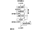
- the demultiplexing unit 21 extracts the signal code and the code corresponding to the quantization width
- the lossless decoding unit 22 performs lossless decoding of the signal code
- the inverse quantization unit 23 is decoded.
- the quantized signal is inversely quantized to obtain the original signal.
- Non-Patent Document 1 the amount of information required is increased by the amount of filter coefficients as compared with simple lossy compression coding as shown in FIGS.
- auditory weighting only needs to satisfy the following two properties, and strict information is often unnecessary. 1.
- a signal value or a frequency spectrum value of the signal is given a relatively small weight and a small value is given a relatively large weight. 2.
- a relatively small weight is applied to the vicinity of the peak of the signal or the frequency spectrum of the signal in the same manner as the peak.
- the present invention combines the above two properties and transforms the sample sequence by pre-processing and post-processing that do not require auxiliary information for post-processing, thereby improving the auditory quality of sound signal encoding processing and decoding processing.
- the purpose is to increase.
- the sample string transformation device encodes a weighted frequency domain signal obtained by transforming a frequency domain signal corresponding to an input acoustic signal.
- a sample sequence transformation device for obtaining a weighted frequency domain signal corresponding to a weighted time domain signal for performing a frequency domain signal from a sample sequence of a frequency domain signal corresponding to an input acoustic signal for each predetermined time interval For each frequency interval of a plurality of samples smaller than the number of frequency samples in the signal sample sequence, the frequency interval is calculated from the sample value of the sample included in the frequency interval.
- a representative value calculation unit for calculating a value, a weight corresponding to the function value of the representative value by a companding function capable of defining an inverse function for each predetermined time interval, and the representative value in the sample sequence of the frequency domain signal A signal companding unit that obtains a frequency domain sample sequence multiplied by each sample as a sample sequence of a weighted frequency domain signal.
- the sample string transformation device is a decoded acoustic signal from a weighted frequency domain signal obtained by a decoding device or a weighted frequency domain signal corresponding to a weighted time domain signal obtained by a decoding device.
- a sample sequence transformation device that obtains a frequency domain signal corresponding to a plurality of samples from a sample sequence of a weighted frequency domain signal that is smaller than the number of frequency samples in the sample sequence of the weighted frequency domain signal for each predetermined time interval.
- a companding representative value calculation unit that calculates a representative value of the frequency section from a sample value of a sample included in the frequency section for each frequency section, and a representative value by a companding function that can define an inverse function for each predetermined time section
- a frequency domain sample sequence obtained by multiplying the weight corresponding to the function value by each sample corresponding to the representative value in the sample sequence of the weighted frequency domain signal.
- a sample string transformation device that receives a weighted acoustic signal or an input acoustic signal for input to an encoding device that encodes a weighted acoustic signal obtained by transforming an input acoustic signal.
- a sample train deformation device for obtaining a weighted acoustic signal corresponding to a weighted frequency domain signal to be input to an encoding device for encoding a weighted frequency domain signal corresponding to the weighted acoustic signal obtained by deformation.
- a representative value calculation unit that calculates a representative value of the time interval, a weight corresponding to the function value of the representative value by a companding function that can define an inverse function for each predetermined time interval, and an input acoustic signal
- a time-series weighted acoustic signal corresponding to a time-domain weighted acoustic signal obtained by a decoding apparatus or a frequency-domain weighted acoustic signal obtained by a decoding apparatus.
- a sample sequence transformation device that obtains a decoded acoustic signal from a signal, by a plurality of samples less than the number of samples in the sample sequence of the weighted acoustic signal from the sample sequence of the weighted acoustic signal in the time domain for each predetermined time interval
- a companding representative value calculation unit that calculates a representative value of the time interval from the sample value of the sample included in the time interval, and a representative value by a companding function that can define an inverse function for each predetermined time interval
- the time domain sample sequence obtained by multiplying the weight corresponding to the function value of each of the samples corresponding to the representative value in the sample sequence of the weighted acoustic signal with the sample sequence of the decoded acoustic signal Including a signal inverse companding unit obtained by.
- the auditory quality of the encoding process and the decoding process can be improved.
- FIG. 1 is a diagram illustrating a functional configuration of a conventional encoding device.
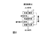
- FIG. 2 is a diagram illustrating a functional configuration of a conventional decoding device.
- FIG. 3 is a diagram illustrating a functional configuration of a conventional encoding device.
- FIG. 4 is a diagram illustrating a functional configuration of a conventional decoding device.
- FIG. 5 is a diagram illustrating a functional configuration of the encoding device according to the first embodiment and the second embodiment.
- FIG. 6 is a diagram illustrating a functional configuration of the decoding devices according to the first embodiment and the second embodiment.
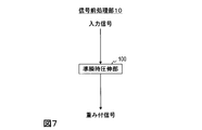
- FIG. 7 is a diagram illustrating a functional configuration of the signal preprocessing unit according to the first embodiment.
- FIG. 1 is a diagram illustrating a functional configuration of a conventional encoding device.
- FIG. 2 is a diagram illustrating a functional configuration of a conventional decoding device.
- FIG. 3 is a diagram illustrating a functional configuration of a conventional encoding device.
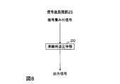
- FIG. 8 is a diagram illustrating a functional configuration of the signal post-processing unit according to the first embodiment.
- FIG. 9 is a diagram illustrating a functional configuration of the quasi-instantaneous companding unit according to the first embodiment.
- FIG. 10 is a diagram illustrating a functional configuration of the quasi-instantaneous reverse companding unit according to the first embodiment.
- FIG. 11 is a diagram illustrating a processing procedure of the encoding method according to the embodiment.
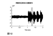
- FIG. 12 is a diagram illustrating an acoustic signal before quasi-instantaneous companding.
- FIG. 13 is a diagram illustrating a sample section before quasi-instantaneous companding.
- FIG. 14 is a diagram illustrating a sample interval after quasi-instantaneous companding.
- FIG. 12 is a diagram illustrating an acoustic signal before quasi-instantaneous companding.
- FIG. 13 is a diagram illustrating a sample section before quasi-instantaneous compand
- FIG. 15 is a diagram illustrating a weighted signal after quasi-instantaneous companding.
- FIG. 16 is a diagram illustrating a processing procedure of the decoding method according to the embodiment.
- FIG. 17 is a diagram illustrating a decoding weighted signal before quasi-instantaneous reverse companding.
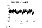
- FIG. 18 is a diagram illustrating a sample section before quasi-instantaneous reverse companding.
- FIG. 19 is a diagram illustrating a sample interval after quasi-instantaneous reverse companding.
- FIG. 20 is a diagram illustrating an output signal after quasi-instantaneous reverse companding.
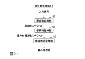
- FIG. 21 is a diagram illustrating a functional configuration of a signal preprocessing unit according to the second embodiment.
- FIG. 21 is a diagram illustrating a functional configuration of a signal preprocessing unit according to the second embodiment.
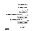
- FIG. 22 is a diagram illustrating a functional configuration of a signal post-processing unit according to the second embodiment.
- FIG. 23 is a diagram illustrating a functional configuration of the quasi-instantaneous companding unit according to the second embodiment.
- FIG. 24 is a diagram illustrating a functional configuration of the quasi-instantaneous reverse companding unit according to the second embodiment.
- FIG. 25 is a diagram illustrating a functional configuration of the encoding device according to the third embodiment and the fourth embodiment.
- FIG. 26 is a diagram illustrating a functional configuration of the decoding devices according to the third embodiment and the fourth embodiment.
- FIG. 27 is a diagram illustrating a functional configuration of a signal preprocessing unit according to the third embodiment.
- FIG. 28 is a diagram illustrating a functional configuration of a signal post-processing unit according to the third embodiment.
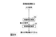
- FIG. 29 is a diagram illustrating a functional configuration of a signal preprocessing unit according to the fourth embodiment.
- FIG. 30 is a diagram illustrating a functional configuration of a signal post-processing unit according to the fourth embodiment.
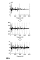
- FIG. 31 is a diagram illustrating frequency spectra before and after quasi-instantaneous companding according to the fifth embodiment.
- FIG. 32 is a diagram illustrating a functional configuration of the quasi-instantaneous companding unit according to the sixth embodiment.
- FIG. 33 is a diagram illustrating a functional configuration of the quasi-instantaneous reverse companding section according to the sixth embodiment.
- FIG. 34 is a diagram illustrating frequency spectra before and after quasi-instantaneous companding according to the sixth embodiment.
- FIG. 35 is a diagram illustrating a functional configuration of the sample train deforming device according to the seventh embodiment.
- FIG. 36 is a diagram illustrating a functional configuration of the sample train deforming device according to the seventh embodiment.
- FIG. 37 is a diagram illustrating a functional configuration of the encoding device according to the eighth embodiment.
- FIG. 38 is a diagram illustrating a functional configuration of the decoding device according to the eighth embodiment.
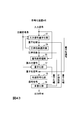
- FIG. 39 is a diagram illustrating a processing procedure of the encoding method according to the eighth embodiment.
- FIG. 40 is a diagram illustrating a processing procedure of the decoding method according to the eighth embodiment.
- FIG. 41 is a diagram illustrating a functional configuration of the encoding device according to the ninth embodiment.
- FIG. 42 is a diagram illustrating a processing procedure of the encoding method according to the ninth embodiment.
- FIG. 43 is a diagram illustrating a functional configuration of an encoding device according to a modification of the ninth embodiment.
- FIG. 44 is a diagram illustrating a processing procedure of the encoding method according to the modified example of the ninth embodiment.
- FIG. 45 is a diagram illustrating a functional configuration of the decoding device according to the ninth embodiment.
- FIG. 46 is a diagram illustrating a processing procedure of the decoding method according to the ninth embodiment.
- FIG. 47 is a diagram illustrating a functional configuration of the signal encoding device according to the tenth embodiment.
- FIG. 48 is a diagram illustrating a functional configuration of the signal decoding apparatus according to the tenth embodiment.
- FIG. 49 is a diagram for explaining a mechanism for improving auditory quality.
- the first embodiment of the present invention includes an encoding device 1 and a decoding device 2.
- the encoding device 1 encodes a sound signal (acoustic signal) such as voice or music input in units of frames to obtain a code and outputs it.
- the code output from the encoding device 10 is input to the decoding device 20.
- the decoding device 20 decodes the input code and outputs an acoustic signal in units of frames.
- the encoding device 1 of the first embodiment includes a signal preprocessing unit 10, a quantization unit 17, a lossless encoding unit 18, and a multiplexing unit 19, as shown in FIG. That is, the signal preprocessing unit 10 is added to the conventional encoding device 91 shown in FIG.
- the decoding device 2 of the first embodiment includes a demultiplexing unit 21, a lossless decoding unit 22, an inverse quantization unit 23, and a signal post-processing unit 25. That is, the signal post-processing unit 25 is added to the conventional decoding device 92 shown in FIG.
- the encoding device 1 and the decoding device 2 are loaded with a special program in a known or dedicated computer having, for example, a central processing unit (CPU), a main storage device (Random access memory, RAM), and the like. It is a special device constructed.
- the encoding device 1 and the decoding device 2 execute each process under the control of the central processing unit.
- the data input to the encoding device 1 and the decoding device 2 and the data obtained in each process are stored in, for example, the main storage device, and the data stored in the main storage device is read out as necessary. It is used for processing.
- at least a part of each processing unit of the encoding device 1 and the decoding device 2 may be configured by hardware such as an integrated circuit.
- the signal preprocessing unit 10 of the encoding device 1 and the signal postprocessing unit 25 of the decoding device 2 perform a “quasi-instantaneous companding” process.
- the quasi-instantaneous companding is a conversion in which sample values within a predetermined interval are grouped together and the sample values are compressed or expanded according to the representative value.
- the signal preprocessing unit 10 includes a quasi-instantaneous companding unit 100.
- the signal post-processing unit 25 includes a quasi-instantaneous reverse companding unit 250 as shown in FIG.
- the quasi-instantaneous companding unit 100 includes a representative value calculating unit 110 and a signal companding unit 120.
- the quasi-instantaneous reverse companding unit 250 includes a companding representative value calculating unit 260 and a signal reverse companding unit 270.
- the encoding device 1 adaptively weights the input signal using quasi-instantaneous companding that does not require auxiliary information as preprocessing to obtain a weighted signal, and the quantum signal similar to the prior art is applied to the weighted signal. And lossless encoding.
- the decoding device 2 receives the code as input and performs lossless decoding and inverse quantization similar to those of the prior art, and reverses the quasi-instantaneous companding of the encoding device 1 using quasi-instantaneous companding that does not require auxiliary information as post-processing. Is applied to the weighted signal.
- the encoding device 1 and the decoding device 2 of the first embodiment can audibly reduce quantization distortion by these processes.
- the acoustic signal X k input to the encoding device 1 is input to the signal preprocessing unit 10.
- One of the predetermined feature amounts is calculated as a representative value and output.
- the representative value may be calculated using, for example, a part of M ′ ( ⁇ M) samples in the section of M samples as follows.
- M ′ is the number of samples used for calculating the representative value
- G m is the number of the sample used for calculating the predetermined representative value.
- the companding function f (x) is an arbitrary function that can define the inverse function f ⁇ 1 (y).
- the companding function f (x) for example, the following generalized logarithmic function can be used.
- ⁇ and ⁇ are predetermined positive numbers.
- companding function f (x) by the conversion after the representative value f (- X m) and the original representative value - with X m, the sample value X k of the audio signal for each section by M samples, the following Thus, it is transformed into a weighted signal Yk .
- first representative value by using the companding function f (x) - converts X m, the weight f corresponding to the function value multiplying the X m and the sample values X k - (- X m) /
- a two-stage calculation is performed, such as transformation into a weighted signal Yk .
- the present invention is not limited to such a calculation method, and any calculation method may be used as long as the calculation can obtain the weighted signal Yk .
- a calculation that performs the calculation of Equation (9) in one step may be performed.
- the companding function that can define the inverse function is not limited to the calculation for a single sample value as shown in Equation (7), and is, for example, a function that outputs a calculation result for each sample with a plurality of samples as arguments. It may be defined as a companding function including an operation that further performs an operation capable of performing an inverse operation on a function that can define an inverse function. For example, in equation (9)
- the quasi-instantaneous companding is expressed by a simple constant multiple that depends only on the representative value in each section.
- a representative value from the weighted signal Y k even decoding device 2 - X m can be estimated by reverse without auxiliary information Drawing can be performed.
- the signal Y k is scalar quantized and a quantized signal is output.
- the quantization unit 17 outputs the quantized signal to the lossless encoding unit 18 and the quantization width used for the quantization to the multiplexing unit 19.
- a predetermined quantization width may be used, or if the code length is too long for the target code length based on the code length of the compression result by the lossless encoding unit 18, quantization is performed.
- the search may be performed by increasing the width and decreasing the quantization width when the code length is too short with respect to the target code length.
- the quantization unit 17 may be operated for each frame having the same number of samples N as the signal preprocessing unit 10, or may be operated for each number of samples different from the signal preprocessing unit 10, for example, every 2N samples. .
- the lossless encoding unit 18 receives the quantized signal output from the quantizing unit 17, assigns a code corresponding to the quantized signal by lossless encoding, and outputs a signal code.
- the lossless encoding unit 18 outputs the signal code to the multiplexing unit 19.
- general entropy encoding may be used, or an existing lossless encoding method such as MPEG-ALS (see Reference 1) or G.711.0 (see Reference 2) is used. Also good.
- the lossless encoding unit 18 may be operated for each frame having the same number of samples N as the signal preprocessing unit 10, or may be operated for each number of samples different from the signal preprocessing unit 10, for example, every 2N samples.
- Good. [Reference 1] T. Liebechen, T. Moriya, N. Harada, Y. Kamamoto, and YA Reznik, “The MPEG-4 Audio Lossless Coding (ALS) standard-technology and applications,” in Proc. AES 119th Convention, Paper # 6589, Oct., 2005. [Reference 2] ITU-T G.711.0, “Lossless compression of G.711 pulse code modulation,” 2009.
- the multiplexing unit 19 receives the quantization width output from the quantization unit 17 and the signal code output from the lossless encoding unit 18, receives a quantization width code that is a code corresponding to the quantization width, and Together with the signal code, it is output as an output code.
- the quantization width code is obtained by encoding the quantization width value.
- a known encoding method may be used as a method of encoding the quantization width value.
- the multiplexing unit 19 may be operated for each frame having the same number of samples N as the signal preprocessing unit 10, or may be operated for each number of samples different from the signal preprocessing unit 10, for example, every 2N samples. .
- FIGS. 12 to 15 show specific examples of the process in which the input acoustic signal is deformed by the preprocessing of the encoding method of the first embodiment.
- FIG. 12 shows a signal waveform of the acoustic signal Xk in the time domain. The horizontal axis represents time, and the vertical axis represents amplitude.
- FIG. 12 shows a sound signal X k from 0 seconds to 2 seconds.
- FIG. 13 shows a signal waveform of an acoustic signal in a section of M samples cut out at positions separated by dotted lines in FIG. 12 in order to calculate a representative value. A representative value is calculated from the M samples included in the section of 1.28 seconds to 1.36 seconds shown in FIG.
- FIG. 12 shows a signal waveform of the acoustic signal Xk in the time domain. The horizontal axis represents time, and the vertical axis represents amplitude.
- FIG. 12 shows a sound signal X k from 0 seconds to 2 seconds.
- FIG. 14 is a signal waveform of a weighted signal of a section of M samples after weighting according to the function value of the representative value by the companding function. Compared to FIG. 13, it can be seen that the amplitude value is converted without changing the shape of the waveform.
- FIG. 15 shows the signal waveform of the weighted signal Yk that is finally output from the signal preprocessing unit. Compared with FIG. 12, it can be seen that the whole is drawn.
- the demultiplexing unit 21 receives the code input to the decoding device 2, and outputs the signal code to the lossless decoding unit 22 and the quantization width corresponding to the quantization width code to the inverse quantization unit 23, respectively. .
- the quantization width corresponding to the quantization width code is obtained by decoding the quantization width code.
- a decoding method corresponding to a known encoding method in which the quantization width is encoded may be used.
- the signal post-processing unit 25 operates for each frame having the number of samples N as described below, but the multiplexing unit 19 may be operated for each frame having the same number of samples N as the signal post-processing unit 25. The operation may be performed every number of samples different from the post-processing unit 25, for example, every 2N samples.
- the lossless decoding unit 22 receives the signal code output from the demultiplexing unit 21, performs lossless decoding corresponding to the processing of the lossless encoding unit 18, and reverses the signal corresponding to the signal code as a decoded quantized signal.
- the data is output to the quantization unit 23.
- the lossless decoding unit 22 may be operated for each frame having the same number of samples N as the signal post-processing unit 25, or may be operated for each number of samples different from the signal post-processing unit 25, for example, every 2N samples. .
- the inverse quantization unit 23 receives the decoded quantized signal output from the lossless decoding unit 22 and the quantization width output from the demultiplexing unit 21, and corresponds to the quantization width, for example, as in the prior art.
- the value to be multiplied by each sample value of the decoded quantized signal is multiplied for each sample to obtain a dequantized signal.
- the inverse quantization unit 23 may be operated for each frame having the same number of samples N as the signal post-processing unit 25, or may be operated for each number of samples different from the signal post-processing unit 25, for example, every 2N samples. Good.
- Companding representative value - calculation method of Y m are used the same as the representative value calculation unit 110 of the encoding apparatus 1 corresponding to the decoding apparatus 2.
- the companding representative value calculated here (the companding representative value calculating unit 260) is quantized by the encoding device 1.
- the representative value calculated by the representative value calculation unit 110 of the encoding device 1 is equal to the value obtained by converting with the companding function, and there is quantization distortion in the encoding device 1.
- the value obtained by converting the representative value calculated by the representative value calculation unit 110 of the encoding device 1 by the companding function is almost the same value. Therefore, the signal representative companding unit 270 in the latter stage can invert the companding representative value using the inverse function of the companding function to estimate the original representative value, and the reverse companding can be performed without auxiliary information. It can be carried out.
- FIG. 17 to 20 show specific examples of the process in which the decoding weighted signal is transformed by the post-processing of the decoding method of the first embodiment.
- FIG. 17 shows a signal waveform of the decoding weighted signal ⁇ Yk obtained by the decoding method. The horizontal axis represents time, and the vertical axis represents amplitude. In the example of FIG. 17, the decoding weighted signal ⁇ Y k from 0 second to 2 seconds is shown.
- FIG. 18 is a signal waveform of a decoding weighted signal in a section of M samples cut out at positions separated by dotted lines in FIG. 17 in order to calculate a companding representative value. A companding representative value is calculated from the M samples included in the section of 1.28 seconds to 1.36 seconds shown in FIG.
- FIG. 19 shows the signal waveform of the output signal in the section of M samples after weighting according to the function value of the companding representative value by the inverse function of the companding function. Compared to FIG. 18, it can be seen that the amplitude value is converted without changing the shape of the waveform.
- FIG. 20 shows the signal waveform of the output signal ⁇ X k that is finally output from the signal post-processing section. Compared with FIG. 17, it turns out that it is reverse-drawn as a whole.
- the signal pre-processing unit 10 and the signal post-processing unit 25 of the first embodiment perform the quasi-instantaneous companding process with the time domain signal, but the signal weighting by the quasi-instantaneous companding is performed even in the frequency domain. In particular, quantization distortion can be reduced.
- the signal preprocessing unit and the signal postprocessing unit are processed in the frequency domain.
- the encoding device 3 of the second embodiment includes a signal preprocessing unit 11, a quantization unit 17, a lossless encoding unit 18, and a multiplexing unit 19, as shown in FIG. That is, the processing of the signal preprocessing unit is different from that of the encoding device 1 of the first embodiment.
- the decoding device 4 according to the second embodiment includes a demultiplexing unit 21, a lossless decoding unit 22, an inverse quantization unit 23, and a signal post-processing unit 26. That is, the signal post-processing unit is different from the decoding device 2 of the first embodiment.
- the signal preprocessing unit 11 includes a frequency conversion unit 130, a quasi-instantaneous companding unit 101, and a frequency inverse conversion unit 140.
- the signal post-processing unit 26 includes a frequency conversion unit 280, a quasi-instantaneous reverse companding unit 251, and a frequency reverse conversion unit 290, as shown in FIG.
- the quasi-instantaneous companding unit 101 includes a representative value calculating unit 111 and a signal companding unit 121 as shown in FIG.
- the quasi-instantaneous reverse companding unit 251 includes a companding representative value calculating unit 261 and a signal reverse companding unit 271 as shown in FIG.
- the quasi-instantaneous companding part 101 and the quasi-instantaneous counter-compressing part 251 are different from the quasi-instantaneous companding part 100 and the quasi-instantaneous inverse companding part 250 of the first embodiment in that the input / output is a frequency spectrum. .
- the acoustic signal x n input to the encoding device 3 is input to the signal preprocessing unit 11.
- ⁇ Third embodiment> The signal preprocessing unit 11 and the signal postprocessing unit 26 of the second embodiment performed quasi-instantaneous companding in the frequency domain, and then returned to the time domain to perform encoding and decoding processing.
- encoding and decoding processes are performed in the frequency domain without returning to the time domain.
- the encoding device 5 of the third embodiment includes a signal preprocessing unit 12, a quantization unit 17, a lossless encoding unit 18, and a multiplexing unit 19. That is, the processing of the signal preprocessing unit is different from that of the encoding device 3 of the second embodiment.
- the decoding device 6 according to the third embodiment includes a demultiplexing unit 21, a lossless decoding unit 22, an inverse quantization unit 23, and a signal post-processing unit 27. That is, the signal post-processing unit is different from the decoding device 4 of the second embodiment.
- the signal preprocessing unit 12 includes a frequency conversion unit 130 and a quasi-instantaneous companding unit 101 as shown in FIG. That is, it differs from the signal preprocessing unit 11 of the second embodiment in that the frequency inverse transform unit 140 is not included and a weighted frequency spectrum is output.
- the signal post-processing unit 27 includes a quasi-instantaneous reverse companding unit 251 and a frequency inverse converting unit 290. That is, it differs from the signal post-processing unit 26 of the second embodiment in that the frequency conversion unit 280 is not included and a decoding weighted frequency spectrum is input.
- the quantization unit 17, the lossless encoding unit 18, the lossless decoding unit 22, and the inverse quantization unit 23 are the same as the quantization unit 17, the lossless encoding unit 18, the lossless decoding unit 22, and the inverse quantization unit 23 of the second embodiment. Although the same processing is performed, it is different from the second embodiment in that a frequency spectrum is handled instead of the time domain signal.
- the processing of the frequency conversion unit 130 and the quasi-instantaneous companding unit 101 is the same as that in the second embodiment described above.
- the lossless decoding unit 22 receives the signal code output from the demultiplexing unit 21, performs lossless decoding corresponding to the processing of the lossless encoding unit 18, and dequantizes the frequency spectrum corresponding to the signal code as a decoded quantized frequency spectrum. To the unit 23.
- the inverse quantization unit 23 receives the decoded quantized frequency spectrum output from the lossless decoding unit 22 and the quantization width output from the demultiplexing unit 21, and, for example, in the same manner as in the prior art, a value corresponding to the quantization width and Each sample value of the decoded quantized frequency spectrum is multiplied for each sample to obtain a dequantized signal.
- the processes of the quasi-instantaneous reverse companding unit 251 and the frequency reverse converting unit 290 are the same as those in the second embodiment described above.
- the signal preprocessing unit 10 and the signal postprocessing unit 25 of the first embodiment performed the quasi-instantaneous companding process on the time domain signal, and then performed the encoding and decoding processes in the time domain.
- the quasi-instantaneous companding process is performed with the time domain signal, and then the signal is converted into the frequency domain to be encoded and decoded.
- the encoding device 7 according to the fourth embodiment includes a signal preprocessing unit 13, a quantization unit 17, a lossless encoding unit 18, and a multiplexing unit 19, as shown in FIG. That is, the processing of the signal preprocessing unit is different from that of the encoding device 1 of the first embodiment.
- the decoding device 8 of the fourth embodiment includes a demultiplexing unit 21, a lossless decoding unit 22, an inverse quantization unit 23, and a signal post-processing unit 28. That is, the signal post-processing unit is different from the decoding device 2 of the first embodiment.
- the signal pre-processing unit 13 includes a quasi-instantaneous companding unit 100 and a frequency converting unit 130 as shown in FIG. That is, as compared with the signal preprocessing unit 10 of the first embodiment, the frequency converter 130 is connected to the subsequent stage of the quasi-instantaneous companding unit 100 and a weighted frequency spectrum is output.
- the signal post-processing unit 28 includes a frequency reverse conversion unit 290 and a quasi instantaneous reverse companding unit 250, as shown in FIG. That is, the difference from the signal post-processing unit 25 of the first embodiment is that the frequency inverse transform unit 290 is connected to the preceding stage of the quasi-instantaneous reverse companding unit 250 and the decoded weighted frequency spectrum is input.
- the quantization unit 17, the lossless encoding unit 18, the lossless decoding unit 22, and the inverse quantization unit 23 are the same as the quantization unit 17, the lossless encoding unit 18, the lossless decoding unit 22, and the inverse quantization unit 23 of the first embodiment. Although the same processing is performed, it is different from the first embodiment in that a frequency spectrum is handled instead of the time domain signal.
- the acoustic signal x n input to the encoding device 7 is input to the signal preprocessing unit 13.
- the processing of the frequency conversion unit 130 is the same as that in the second embodiment described above.
- the lossless decoding unit 22 receives the signal code output from the demultiplexing unit 21, performs lossless decoding corresponding to the processing of the lossless encoding unit 18, and dequantizes the frequency spectrum corresponding to the signal code as a decoded quantized frequency spectrum. To the unit 23.
- the inverse quantization unit 23 receives the decoded quantized frequency spectrum output from the lossless decoding unit 22 and the quantization width output from the demultiplexing unit 21, and, for example, in the same manner as in the prior art, a value corresponding to the quantization width and Each sample value of the decoded quantized frequency spectrum is multiplied for each sample to obtain a dequantized signal.
- the processing of the frequency inverse transform unit 290 is the same as that in the second embodiment described above.
- ⁇ Points from the first embodiment to the fourth embodiment> In the first embodiment, a configuration has been described in which preprocessing and postprocessing are performed in the time domain, and encoding processing and decoding processing are performed in the time domain. In the second embodiment, a configuration has been described in which preprocessing and postprocessing are performed in the frequency domain, and encoding processing and decoding processing are performed in the time domain. In the third embodiment, a configuration has been described in which preprocessing and postprocessing are performed in the frequency domain, and encoding processing and decoding processing are performed in the frequency domain. In the fourth embodiment, a configuration has been described in which preprocessing and postprocessing are performed in the time domain, and encoding processing and decoding processing are performed in the frequency domain.
- the pre-processing and post-processing, and the encoding processing and decoding processing can be performed in any combination of frequency domain and time domain.
- the pre-processing and post-processing of the present invention are applicable to both frequency domain encoding processing and decoding processing and time domain encoding processing and decoding processing.
- a plurality of sample sections for performing the quasi-instantaneous companding process can be inversely transformed without using auxiliary information, regardless of how long the section is determined in advance.
- auditory quality is taken into consideration, it is possible to more appropriately determine a plurality of sample intervals for performing the quasi-instantaneous companding process.
- L intervals be [K 0 K 1 ], [K 1 K 2 ],..., [K L-1 K L ]
- K m-1 K m ] represents that the (K m-1 +1) -th sample to the K m- th sample in the frame are defined as the m-th interval.
- the processing interval can be set finer as the frequency is lower, and the processing interval coarser as the frequency is higher.
- Companding function f (x) by the conversion after the representative value f (- X m) and the original representative value - with X m, the sample value X of the frequency spectrum for each the L section including a sample number a predetermined k is transformed into a weighted frequency spectrum Y k as follows.
- the decoding device of the fifth embodiment is obtained by changing the processes of the companding representative value calculation unit 261 and the signal reverse companding unit 271 in the decoding device 4 of the second embodiment as follows.
- FIG. 31 shows a specific example of a frequency spectrum when signal companding is performed by dividing the section more finely as the low frequency and coarser as the high frequency by the preprocessing of the encoding method of the fifth embodiment.
- the frequency band of 0 to 2000 Hz is divided into 5 sections, and for example, the frequency band of 5000 Hz to 8000 Hz is all included in one section, and is finer as the low frequency and coarser as the high frequency.
- the processing section is set as follows.
- ⁇ Sixth embodiment> When a signal that has no undulations in the spectrum and shows a uniformly large value is subjected to quasi-instantaneous companding by finely dividing the section, the spectrum value in the frame is uniformly reduced. In other words, the quantization performance may be adversely affected.
- a quasi-instantaneous companding process is hierarchically used as a countermeasure. For example, quasi-instantaneous companding is first performed in a rough section in the frame, and the value of a section with high energy is increased using, for example, an inverse function of the companding function. Thereafter, quasi-instantaneous companding is performed in a finer section. In the inverse transformation, first, quasi-instantaneous reverse companding is performed in a fine section, and then, the original frequency spectrum is obtained by performing quasi-instantaneous reverse companding in a rough section.
- the encoding device of the sixth embodiment is obtained by changing the processing of the quasi-instantaneous companding unit 101 in the encoding device 3 of the second embodiment as follows.
- the configuration of the sixth embodiment can be applied to the second embodiment, and can be applied to all the embodiments from the first embodiment to the fifth embodiment.
- the quasi-instantaneous companding unit 102 of the sixth embodiment includes a representative value calculating unit 112 and a signal companding unit 122, and the output of the signal companding unit 122 is input to the representative value calculating unit 112. Configured to be
- the sample number M of the section for which the representative value calculation unit 112 obtains the representative value may be configured to be different every time it is repeated.
- Companding function f (x) by the conversion after the representative value f (- X m) and the original representative value - with X m, the sample values ⁇ X k of the frequency spectrum for each section of the M samples, as follows It is transformed into a weighted frequency spectrum Yk .
- the companding function f (x) used by the signal companding unit 122 may be configured to use a different one each time it is repeated. For example, the inverse function f ⁇ 1 (x) of the companding function f (x) is used for the first time, and the companding function f (x) is used for the second time.
- the decoding device of the sixth embodiment is obtained by changing the processing of the quasi-instantaneous reverse companding unit 251 in the decoding device 4 of the second embodiment as follows.
- the configuration of the sixth embodiment can be applied to the second embodiment, and can be applied to all the embodiments from the first embodiment to the fifth embodiment.
- the quasi-instantaneous reverse companding unit 252 of the sixth embodiment includes a companding representative value calculating unit 262 and a signal reverse companding unit 272, and the output of the signal reverse companding unit 272 is a companding representative. It is configured to be input to the value calculation unit 262.
- Companding representative value - calculation method of Y m are used the same as the representative value calculation unit 112 of the coding apparatus corresponding to the decoding apparatus.
- the number of samples M in the section for which the companding representative value calculation unit 262 obtains the companding representative value corresponds to the number of samples M used by the representative value calculating unit 112 of the encoding device corresponding to the decoding device each time it is repeated.
- Companding function f companding representative value was converted by the inverse function f -1 (y) of (x) f -1 (- Y m) and the original companding representative values - with Y m, predetermined M samples of the section Every time, the sample value ⁇ Y k of the decoding weighted frequency spectrum is transformed into the sample value of the decoding frequency spectrum ⁇ X k as follows.
- the inverse function f ⁇ 1 (y) of the companding function f (x) used by the signal inverse companding unit 272 is an inverse function corresponding to the companding function f (x) used by the signal companding unit 122 every time it is repeated. It is configured to use.
- the companding function f (x) is used as the inverse function of the inverse function f ⁇ 1 (x) of the companding function f (x) at the first time, and the inverse function with respect to the companding function f (x) is performed the second time.
- the inverse function f ⁇ 1 (x) of the companding function f (x) is used as
- FIG. 34 shows a specific example of a frequency spectrum when the representative value calculation and the signal companding process are repeated a plurality of times by the preprocessing of the encoding method of the sixth embodiment.
- the quasi-instantaneous reverse companding unit 251 included in the unit 250 and the decoding devices 4 and 6 can also be configured as an independent sample train deforming device.
- This sample sequence transformation device 33 is a weighted frequency domain signal for input to an encoding device for encoding a weighted frequency domain signal obtained by transforming a frequency domain signal corresponding to an input acoustic signal, or an input acoustic signal.
- a weighted frequency domain corresponding to a weighted time domain signal for input to an encoding device for encoding a weighted time domain signal corresponding to a weighted frequency domain signal obtained by modifying a frequency domain signal corresponding to the signal For example, as shown in FIG.
- the sample train deforming apparatus for obtaining a signal includes a representative value calculating unit 111 and a signal companding unit 121.
- the representative value calculation unit 111 calculates, for each predetermined time interval, from the sample sequence of the frequency domain signal corresponding to the input acoustic signal, for each frequency interval with a plurality of samples less than the number of frequency samples in the frequency domain sample sequence, The representative value of the frequency section is calculated from the sample values of the included samples.
- the signal companding unit 121 includes, for each predetermined time interval, a weight corresponding to the function value of the representative value by the companding function that can define an inverse function, and each sample corresponding to the representative value in the frequency domain sample sequence.
- the multiplied frequency domain sample sequence is obtained as a sample sequence of the weighted frequency domain signal.
- This sample sequence transformation device 34 is a weighted frequency domain signal obtained by a decoding device that obtains a weighted frequency domain signal corresponding to a frequency domain signal corresponding to a decoded acoustic signal, or a frequency domain corresponding to a decoded acoustic signal.
- the companding representative value calculation unit 261 performs, for each predetermined time interval, from the sample sequence of the weighted frequency domain signal, the frequency segment for each frequency segment by a plurality of samples smaller than the number of frequency samples in the sample sequence of the weighted frequency domain signal.
- the representative value of the frequency section is calculated from the sample values of the samples included in.
- the signal reverse companding unit 271 corresponds to a weight corresponding to a function value of a representative value by a companding function capable of defining an inverse function for each predetermined time interval, and the representative value in the sample sequence of the weighted frequency domain signal.
- a frequency domain sample sequence obtained by multiplying each sample is obtained as a sample sequence of the frequency domain signal corresponding to the decoded acoustic signal.
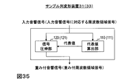
- This sample string transformation device 31 is a weighted acoustic signal for input to an encoding device that encodes a weighted acoustic signal obtained by transforming an input acoustic signal, or a weight obtained by transforming an input acoustic signal.
- a sample-sequence modification device that obtains a weighted acoustic signal corresponding to a weighted frequency domain signal for input to an encoding device that encodes a weighted frequency domain signal corresponding to the attached acoustic signal, for example, FIG.
- the representative value calculation unit 110 and the signal companding unit 120 are included.
- the representative value calculation unit 110 is included in the time interval for each predetermined time interval from a sample sequence of the input acoustic signal in the time domain to a time interval of a plurality of samples smaller than the number of samples in the sample sequence of the input acoustic signal.
- a representative value of the time interval is calculated from the sample value of the sample.
- the signal companding unit 120 has a weight corresponding to a function value of a representative value by a companding function capable of defining an inverse function for each predetermined time interval, each sample corresponding to the representative value in the sample sequence of the input acoustic signal, and , And a time-domain sample sequence obtained by multiplying and is obtained as a sample sequence of the weighted acoustic signal.
- This sample sequence transformation device 32 obtains a time-domain weighted acoustic signal corresponding to the decoded acoustic signal by decoding.
- FIG. 36 shows a sample train deforming device that obtains a decoded acoustic signal from a weighted acoustic signal in a time domain corresponding to a weighted acoustic signal in a frequency domain obtained by a decoding device that obtains an attached acoustic signal by decoding.
- a companding representative value calculation unit 260 and a signal reverse companding unit 270 are included.
- the companding representative value calculation unit 260 performs, for each predetermined time interval, from the sample sequence of the weighted acoustic signal in the time domain, for each time interval by a plurality of samples less than the number of samples in the sample sequence of the weighted acoustic signal.
- a representative value of the time interval is calculated from the sample values of the samples included in the interval.
- the signal reverse companding unit 270 corresponds to the weight corresponding to the function value of the representative value by the companding function capable of defining the inverse function for each predetermined time interval, and the representative value in the sample sequence of the weighted frequency domain signal.
- a frequency domain sample sequence obtained by multiplying each sample is obtained as a sample sequence of the frequency domain signal corresponding to the decoded acoustic signal.
- the sample string transformation devices 33 and 34 are set so that the number of samples included in the section corresponding to the low frequency is small as the section of the plurality of samples is in the section corresponding to the low frequency, and the number of samples included in the section corresponding to the high frequency is increased.
- the sample row deforming device 35 can be configured.
- the sample string deforming devices 31 to 35 calculate a representative value for each section of a plurality of samples of the input acoustic signal, and multiply each sample of the sample string by a weight corresponding to the calculated function value of the representative value.
- the sample train deforming device 36 can be configured to be repeatedly executed a predetermined number of times.
- the pre-processing by quasi-instantaneous companding and the post-processing by quasi-instantaneous inverse companding have the property of reducing auditory distortion instead of increasing numerical errors such as the square error of the waveform of the decoded signal.
- the pre-processing and the post-processing are used instead of the pre-processing and the post-processing. It is more convenient to compress or process the decoded signal again, aiming to reduce the numerical error of the waveform of the simple decoded signal without using post-processing.
- whether or not to perform pre-processing and post-processing of the signal by quasi-instantaneous companding and quasi-instantaneous reverse companding depends on the quantization width of the frequency domain signal corresponding to the input acoustic signal or the input acoustic signal. Select for each frame based on the value of.
- the eighth embodiment can be applied to the first embodiment, the second embodiment, the fifth embodiment, and the sixth embodiment applied to these embodiments.
- the presence or absence of signal preprocessing is selected based on the value of the quantization width of the input acoustic signal or the frequency domain signal corresponding to the input acoustic signal.
- the decoding device by selecting the presence or absence of post-processing based on the quantization width obtained by decoding, only the frame pre-processed by the encoding device corresponds to the pre-processing performed by the encoding device.
- Post-processing can be performed. That is, the decoding apparatus can perform a decoding process corresponding to the encoding process performed by the encoding apparatus.
- the encoding device 41 according to the eighth embodiment includes a signal preprocessing unit 51, a quantization unit 52, a lossless encoding unit 18, and a multiplexing unit 19. Since the process performed by the quantization unit 52 is complicated in the encoding device 41 of the eighth embodiment, the processing procedure of the encoding method executed by the encoding apparatus 41 of the eighth embodiment is described with reference to FIG. explain.
- the acoustic signal X k input to the encoding device 41 is first input to the quantization unit 52.
- the quantizing unit 52 for example, as in the prior art, to obtain an integer value as a quantized signal by dividing a sound signal X k with a value corresponding to the quantization width.
- the quantization width is increased when the code length is too long for the target code length, and the code length is set to the target code length. If the code length is too short, the search is performed such that the quantization width is reduced. That is, the quantization width is a value obtained by searching and is a value estimated to be optimal.
- step S52 the quantization unit 52 converts the quantized signal into a lossless encoding unit for a frame in which the quantization width used in the quantization in step S51 is smaller than a predetermined threshold value or less than the predetermined threshold value. 18, the quantization width used for quantization is output to the multiplexing unit 19, and for the other frames, information for operating the signal preprocessing unit of the frame is output to the signal preprocessing unit 51. To do.
- step S14 the quantization unit 52 divides the weighted signal Yk by a value corresponding to the quantization width to obtain an integer value as a quantized signal, as in the prior art. For example, based on the code length of the compression result by the lossless encoding unit 18, the quantization width is increased when the code length is too long for the target code length, and the code length is set to the target code length. If the code length is too short, the search is performed such that the quantization width is reduced. That is, the quantization width is a value obtained by searching and is a value estimated to be optimal.
- the quantization width obtained by the search in step S14 is larger than the quantization width obtained by the search in step S51, and is larger than the threshold value in step S52.
- the lower limit value of the quantization width obtained by the search in step S14 is set in step S52. What is necessary is just to set it as the value more than the threshold value in or larger than a threshold value.
- the quantization unit 52 outputs the quantized signal to the lossless encoding unit 18 and the quantization width used for the quantization to the multiplexing unit 19.
- Step S15 performed by the lossless encoding unit 18 and step S16 performed by the multiplexing unit 19 are the same as those in the first embodiment.
- the decoding device 42 includes a demultiplexing unit 61, a lossless decoding unit 22, an inverse quantization unit 23, a determination unit 62, and a signal post-processing unit 63.
- a processing procedure of the decoding method executed by the decoding device 42 of the eighth embodiment will be described.
- step S ⁇ b> 21 the demultiplexing unit 61 receives the code input to the decoding device 42, converts the signal code to the lossless decoding unit 22, and sets the quantization width corresponding to the quantization width code to the inverse quantization unit 23 and the determination unit 62. Respectively.
- the process of obtaining the quantization width by decoding is the same as that of the demultiplexing unit 21.
- Step S22 performed by the lossless decoding unit 22 and step S23 performed by the inverse quantization unit 23 are the same as in the first embodiment.
- the pre-processing and post-processing of signals tend to be necessary as the quantization accuracy of the input acoustic signal and the frequency domain signal corresponding to the input acoustic signal is coarser, and as the quantization accuracy is finer, it becomes unnecessary.
- By adaptively changing the degree of quasi-instantaneous companding for each frame it is possible to apply weighting more in accordance with the signal.
- the encoding device of the ninth embodiment determines the degree of quasi-instantaneous companding in the signal preprocessing for each frame based on the input acoustic signal and the value of the quantization width of the frequency domain signal corresponding to the input acoustic signal. Select and send a coefficient specifying the degree of the selected quasi-instantaneous companding to the decoding device.
- the decoding apparatus according to the ninth embodiment selects, for each frame, the degree of quasi-instantaneous reverse companding in the post-processing of the signal based on the coefficient specifying the degree of quasi-instantaneous companding sent from the encoding apparatus.
- the decoding device also determines the degree of quasi-instantaneous companding used for signal preprocessing in the encoding device based on a coefficient that specifies the degree of quasi-instantaneous companding, and the encoding device performs the processing.
- Post-processing corresponding to the pre-processing can be performed. That is, the decoding apparatus can perform a decoding process corresponding to the encoding process performed by the encoding apparatus.
- ⁇ in Equation (7) is a coefficient that specifies the degree of quasi-instantaneous companding.
- ⁇ which is a coefficient that specifies the degree of quasi-instantaneous companding, is also referred to as companding coefficient.
- the ninth embodiment can be applied to all the embodiments from the first embodiment to the sixth embodiment.
- the encoding device 43 of the ninth embodiment includes a quantization width calculation unit 53, a companding coefficient selection unit 54, a signal preprocessing unit 55, a quantization unit 17, a lossless encoding unit 18, and Multiplexer 56 is included.
- the processing procedure of the encoding method executed by the encoding device 43 of the ninth embodiment will be described.
- the acoustic signal X k input to the encoding device 43 is first input to the quantization width calculation unit 53.
- the quantization width calculation unit 53 determines the quantization width based on, for example, the code length of the compression result by lossless encoding, and if the code length is too long for the target code length.
- the search is performed by increasing the quantization width and decreasing the quantization width when the code length is too short with respect to the target code length. That is, the quantization width is a value obtained by searching and is a value estimated to be optimal.
- the estimated value of the calculated quantization width may be output to the companding coefficient selection unit 54 as the quantization width.
- the companding coefficient selector 54 receives the quantized width output from the quantized width calculator 53 for each frame, and stores a plurality of companding coefficients ⁇ stored in advance in the companding coefficient selector 54.
- One candidate value corresponding to the quantization width value is selected as the companding coefficient ⁇ from the candidate values.
- a companding function is used so that the power of the weighted acoustic signal after companding or the weighted frequency domain signal sample sequence corresponding to the input acoustic signal becomes flat.
- the input acoustic signal and the weighted acoustic signal before and after companding, or between the sample sequence of the frequency domain signal corresponding to the input acoustic signal and the sample sequence of the weighted frequency domain signal A companding function is selected so as to specify a companding function that makes the difference smaller.
- the companding coefficient selection unit 54 outputs the companding coefficient ⁇ obtained by the selection to the signal preprocessing unit 55 and the multiplexing unit 56.
- Step S14 performed by the quantization unit 17 and step S15 performed by the lossless encoding unit 18 are the same as those in the first embodiment.
- the multiplexing unit 56 receives the quantization width output from the quantization unit 17, the signal code output from the lossless encoding unit 18, and the companding coefficient output from the companding coefficient selection unit 54. Then, a quantization width code that is a code corresponding to the quantization width, a companding coefficient code that is a code corresponding to the companding coefficient, and a signal code are output together as an output code.
- the quantization width code is obtained by encoding the quantization width value.
- a known encoding method may be used as a method of encoding method may be used.
- the companding coefficient sign is obtained by encoding the value of the companding coefficient.
- the multiplexing unit 56 may be operated for each frame having the same number of samples N as the signal preprocessing unit 55, or may be operated for each number of samples different from the signal preprocessing unit 55, for example, every 2N samples. .
- an encoding device 45 includes an input signal quantization unit 57, a companding coefficient selection unit 54, a signal preprocessing unit 55, a quantization unit 17, and a lossless encoding unit. 18 and a multiplexing unit 56.
- FIG. 44 the processing procedure of the encoding method executed by the encoding device 45 according to the modification of the ninth embodiment will be described.
- the acoustic signal X k input to the encoding device 45 is first input to the input signal quantization unit 57.
- the input signal quantization unit 57 for example, as in the prior art, to obtain an integer value as a quantized signal by dividing a sound signal X k with a value corresponding to the quantization width.
- the method for obtaining the quantization width is the same as that of the quantization width calculation unit 53 of the encoding device 43 of the ninth embodiment.
- the input signal quantization unit 57 outputs the obtained quantization width to the companding coefficient selection unit 54 and the multiplexing unit 56, and outputs the quantized signal to the lossless encoding unit 18.
- the output of the quantization width to the multiplexing unit 56 and the output of the quantized signal to the lossless encoding unit 18 are controlled by the companding coefficient selection unit 54.
- Step S54 performed by the companding coefficient selector 54 is the same as that of the encoding device 43 of the ninth embodiment.
- the companding coefficient selecting unit 54 outputs the companding coefficient ⁇ obtained by the selection to the signal preprocessing unit 55, and the companding coefficient ⁇ is 1. In this case, control is performed so that the quantized signal obtained by the input signal quantizing unit 57 is input to the lossless encoding unit 18 and the quantization width obtained by the input signal quantizing unit 57 is input to the multiplexing unit 56. In addition, the companding coefficient selection unit 54 outputs the companding coefficient ⁇ to the multiplexing unit 58.
- the signal pre-processing unit 55 receives the companding coefficient ⁇ output from the companding coefficient selecting unit 54.
- Step S14 performed by the quantization unit 17 is the same as that of the encoding device 43 of the ninth embodiment. However, step S14 is performed only when the companding coefficient ⁇ is not 1, that is, when a value other than quasi-instantaneous companding is designated.
- Step S15 performed by the lossless encoding unit 18 and step S55 performed by the multiplexing unit 56 are the same as those of the encoding device 43 of the ninth embodiment.
- the decoding device 44 of the ninth embodiment includes a demultiplexing unit 64, a lossless decoding unit 22, an inverse quantization unit 23, and a signal post-processing unit 65.
- a processing procedure of a decoding method executed by the decoding device 44 of the ninth embodiment will be described.
- step S62 the demultiplexing unit 64 receives the code input to the decoding device 44, receives the signal code to the lossless decoding unit 22, and the companding coefficient ⁇ corresponding to the companding coefficient code to the signal post-processing unit 65.
- the quantization width corresponding to the quantization width code is output to the inverse quantization unit 23, respectively.
- Step S22 performed by the lossless decoding unit 22 and step S23 performed by the inverse quantization unit 23 are the same as in the first embodiment.
- the decoded weighted signal ⁇ Y k and the output signal ⁇ X k are the same. Therefore, the first embodiment using the companding coefficient ⁇ for the decoding weighted signal ⁇ Y k only when the companding coefficient ⁇ is not 1, that is, when a value other than quasi-instantaneous companding is designated.
- the encoding device and the decoding device of the eighth embodiment can be configured as a signal encoding device and a signal decoding device using the sample string transformation device described in the seventh embodiment.
- the signal encoding device using the sample string transformation device of the seventh embodiment is configured as follows.
- the signal encoding device 71 includes the sample string deforming device 31 or 33 of the seventh embodiment, and an encoding device 50 that encodes a signal to be encoded to obtain a signal code.
- the encoding device 50 performs, for example, processing corresponding to other than the signal preprocessing unit 51 of the encoding device 41 of the eighth embodiment, and the sample string transformation device 31 or 33 is, for example, the encoding device of the eighth embodiment.
- the processing corresponding to the 41 signal preprocessing unit 51 is performed.
- the signal encoding device 71 is obtained by obtaining the quantization width for encoding the input acoustic signal or the frequency domain signal corresponding to the input acoustic signal with the target code length by the encoding device 50 for each predetermined time interval.
- the input acoustic signal or a frequency domain signal corresponding to the input acoustic signal is encoded by the encoding device 50 as an encoding target signal
- the input acoustic signal or the frequency domain signal corresponding to the input acoustic signal is input to the sample train deforming device 31 or 33, and the weighted acoustic signal or the weighted frequency obtained by the sample train transforming device 31 or 33 is obtained.
- the sample sequence of the region signal is encoded by the encoding device 50 as an encoding target signal.
- the signal decoding apparatus using the sample string transformation apparatus of the seventh embodiment is configured as follows.
- the signal decoding device 72 includes a sample string transformation device 32 or 34 according to the seventh embodiment, and a decoding device 60 that decodes a signal code to obtain a decoded signal.
- the decoding device 60 performs a process corresponding to, for example, other than the signal post-processing unit 63 of the decoding device 42 according to the eighth embodiment, and the sample string transformation device 32 or 34 performs, for example, a signal of the decoding device 42 according to the eighth embodiment. Processing corresponding to the post-processing unit 63 is performed.
- the signal decoding device 72 decodes the quantization width code and obtains the quantization width by the decoding device 60 every predetermined time interval, and the obtained quantization width is smaller than the predetermined threshold value or less than the predetermined threshold value. For a certain time interval, a signal obtained by decoding the signal code by the decoding device 60 is obtained as a decoded acoustic signal or a frequency domain signal corresponding to the decoded acoustic signal, and for other time intervals, the decoding device 60 obtains the signal.
- the received signal is input to the sample train deforming device 32 or 34 to obtain a decoded acoustic signal or a frequency domain signal corresponding to the decoded acoustic signal.
- the concept of the ninth embodiment can be applied to the sample train deforming device 31 or 33 described in the seventh embodiment to configure as the sample train deforming device 37.
- the sample string deforming device 37 uses the sample string deforming device 31 or 33 to obtain a companding function corresponding to the companding coefficient selected by the quantization width calculating unit and the companding coefficient selecting unit 54 described in the ninth embodiment. It is comprised so that the companding function selection part which performs the process to select may be further included.
- the quantization width calculation unit obtains a quantization width for encoding the input acoustic signal or the frequency domain signal corresponding to the input acoustic signal with the target code length for each predetermined time interval.
- the companding function selector selects the input acoustic signal and the weighted acoustic signal or the sample sequence of the frequency domain signal corresponding to the input acoustic signal and the weight as the quantization width is smaller as the companding function for each predetermined time interval.
- the companding function is selected such that the closer the sample sequence of the weighted frequency domain signal is, or / and the greater the quantization width, the flatter the power of the sample sequence of the weighted acoustic signal or weighted frequency domain signal.
- the quasi-instantaneous companding can perform transformations having the following two properties without adding auxiliary information. 1. In the frame, a signal value or a frequency spectrum value of the signal is given a relatively small weight and a small value is given a relatively large weight. 2. In the frame, a relatively small weight is applied to the vicinity of the peak of the signal or the frequency spectrum of the signal in the same manner as the peak.
- a relatively small weight is applied to the vicinity of the peak of the signal or the frequency spectrum of the signal in the same manner as the peak.
- FIG. 49A shows the frequency spectrum of the quantization error when the original signal is quantized at regular intervals in the time domain. In this case, since the quantization error of a flat spectrum occurs and it is annoying, the auditory quality is deteriorated.
- FIG. 49B shows the frequency spectrum of the quantization error when the companded original signal obtained by companding the original signal is quantized at equal intervals in the time domain. It can be seen that the companding signal and the quantization error have the same flat spectrum.
- FIG. 49C shows a frequency spectrum of a quantization error in the case of reverse companding FIG. In this case, since it becomes a quantization error along the inclination of the spectrum of the original signal, it becomes difficult to hear noise and the auditory quality is improved.
- a representative value is obtained for each sample within a predetermined interval, and based on that representative value
- a general representative value is how to determine - the value of X m is not Motomara, performing the inverse transform I can't.
- the function that determines the representative value is not Motomara, performing the inverse transform I can't.
- the original representative value can also be obtained by the decoding apparatus. Inverse transformation based on this value
- the original sample value can be obtained without using auxiliary information.
- the companded Y k is quantized in the middle, and if an error occurs, the original representative value cannot be obtained correctly, but by performing the same process as above on the quantized Y k , the representative value - estimated value of X m can be calculated, it is possible to perform inverse transform on the basis of its value.
- weighting suitable for auditory characteristics can be performed according to the audio-acoustic signal without adding auxiliary information, and the efficiency of lossy compression coding can be increased. it can.
- the configuration of the fifth embodiment by setting the section used for the quasi-instantaneous companding to be fine at the low frequency and coarse at the high frequency, weighting more suitable for the auditory characteristics can be realized.
- the configuration of the sixth embodiment by using different quasi-instantaneous companding multiple times, more complicated companding can be realized and weighting efficiency can be increased.
- the program describing the processing contents can be recorded on a computer-readable recording medium.
- a computer-readable recording medium for example, any recording medium such as a magnetic recording device, an optical disk, a magneto-optical recording medium, and a semiconductor memory may be used.
- this program is distributed, for example, by selling, transferring, or lending a portable recording medium such as a DVD or CD-ROM in which the program is recorded. Furthermore, the program may be distributed by storing the program in a storage device of the server computer and transferring the program from the server computer to another computer via a network.
- a computer that executes such a program first stores a program recorded on a portable recording medium or a program transferred from a server computer in its own storage device. When executing the process, this computer reads the program stored in its own recording medium and executes the process according to the read program.
- the computer may directly read the program from a portable recording medium and execute processing according to the program, and the program is transferred from the server computer to the computer. Each time, the processing according to the received program may be executed sequentially.
- the program is not transferred from the server computer to the computer, and the above processing is executed by a so-called ASP (Application Service Provider) type service that realizes the processing function only by the execution instruction and result acquisition. It is good.
- ASP Application Service Provider
- the program in this embodiment includes information that is used for processing by an electronic computer and that conforms to the program (data that is not a direct command to the computer but has a property that defines the processing of the computer).
- the present apparatus is configured by executing a predetermined program on a computer.
- a predetermined program on a computer.
- at least a part of these processing contents may be realized by hardware.
Abstract
The present invention improves the performance of processes for encoding and decoding audio signals. A representative value calculation unit 110 calculates, from the sample string of a frequency region signal that corresponds to an input acoustic signal in each prescribed time interval, the representative value of each frequency interval from the sample value of a sample included in each of the frequency intervals, each of the frequency intervals being derived from a plurality of samples that are fewer in number than the number of frequency samples of the sample string of the frequency range signal. In each of the prescribed time intervals, a signal companding unit 120 acquires, as the sample string of a weighted frequency region signal, a frequency region sample string obtained by multiplying a weight that corresponds to the function value of a representative value derived from a companding function with which an inverse function can be defined, and each of the samples in the frequency region sample string that correspond to the representative value.
Description
この発明は、音信号の符号化技術などの信号処理技術において、音信号に由来するサンプル列を、その近傍のサンプル値を基に圧縮または伸長したサンプル列に変形する技術に関する。
The present invention relates to a technique for transforming a sample sequence derived from a sound signal into a sample sequence compressed or expanded based on a sample value in the vicinity thereof in a signal processing technique such as a sound signal encoding technique.
一般的に、不可逆圧縮符号化においては、図1に示すように、量子化部17が入力信号を量子化した後、可逆符号化部18が量子化信号に基づいてエントロピー符号化等の可逆符号化により符号を与え、多重化部19が量子化信号に対応する符号と量子化幅に対応する符号とを合わせて出力する。復号時には、図2に示すように、多重分離部21が信号符号と量子化幅に対応する符号とを取り出し、可逆復号部22が信号符号を可逆復号した後、逆量子化部23が復号された量子化信号を逆量子化して元の信号を得る。
In general, in lossy compression coding, as shown in FIG. 1, after the quantization unit 17 quantizes the input signal, the lossless coding unit 18 uses the lossless code such as entropy coding based on the quantized signal. The multiplexing unit 19 outputs the code corresponding to the quantized signal and the code corresponding to the quantization width together. At the time of decoding, as shown in FIG. 2, the demultiplexing unit 21 extracts the signal code and the code corresponding to the quantization width, the lossless decoding unit 22 performs lossless decoding of the signal code, and then the inverse quantization unit 23 is decoded. The quantized signal is inversely quantized to obtain the original signal.
特に、音声や音楽などの音信号の不可逆圧縮符号化においては、図3に示すように、図1の量子化処理の前に分析部15による信号の分析とフィルタ部16によるフィルタリング処理とを加え、信号に合わせて聴覚特性に適った重みを付与することにより、量子化で生じる誤差を聴覚的に小さくする手法が知られている(非特許文献1参照)。この従来手法では、量子化信号に対応する符号と量子化に用いた量子化幅に対応する符号とに加え、フィルタリングに用いたフィルタ係数に対応する符号も補助情報として復号装置に送り、復号装置は、図4に示すように、図2の逆量子化処理の後処理として、逆フィルタ部24が復号された重み付信号を逆フィルタにかけることで元の信号を得る。
In particular, in irreversible compression coding of sound signals such as speech and music, as shown in FIG. 3, analysis of the signal by the analysis unit 15 and filtering processing by the filter unit 16 are added before the quantization processing of FIG. A method is known in which an error caused by quantization is aurally reduced by assigning a weight suitable for an auditory characteristic in accordance with a signal (see Non-Patent Document 1). In this conventional method, in addition to the code corresponding to the quantized signal and the code corresponding to the quantization width used for quantization, the code corresponding to the filter coefficient used for filtering is also sent to the decoding device as auxiliary information. As shown in FIG. 4, as a post-processing of the inverse quantization process of FIG. 2, the inverse filter unit 24 applies the decoded weighted signal to the inverse filter to obtain the original signal.
非特許文献1に記載された従来技術では、図1~2に示すような単純な不可逆圧縮符号化に比べてフィルタ係数の分だけ必要な情報量が増加してしまう。しかしながら、聴覚的な重み付けは大きく以下の2つの性質を満たしてさえいればよく、厳密な情報が不要なことが多い。1.フレーム内において、信号の値または信号の周波数スペクトルの値が、大きいものには相対的に小さな重みをかけ、小さなものには相対的に大きな重みをかける。2.フレーム内において、信号または信号の周波数スペクトルのピーク近傍には、ピークと同じように相対的に小さな重みをかける。
In the prior art described in Non-Patent Document 1, the amount of information required is increased by the amount of filter coefficients as compared with simple lossy compression coding as shown in FIGS. However, auditory weighting only needs to satisfy the following two properties, and strict information is often unnecessary. 1. In the frame, a signal value or a frequency spectrum value of the signal is given a relatively small weight and a small value is given a relatively large weight. 2. In the frame, a relatively small weight is applied to the vicinity of the peak of the signal or the frequency spectrum of the signal in the same manner as the peak.
この発明は、上記2つの性質を併せ持ち、かつ、後処理のための補助情報が不要な前処理および後処理でサンプル列を変形することにより、音信号の符号化処理および復号処理の聴覚品質を高めることを目的とする。
The present invention combines the above two properties and transforms the sample sequence by pre-processing and post-processing that do not require auxiliary information for post-processing, thereby improving the auditory quality of sound signal encoding processing and decoding processing. The purpose is to increase.
上記の課題を解決するために、この発明の第一の態様のサンプル列変形装置は、入力音響信号に対応する周波数領域信号を変形して得た重み付周波数領域信号を符号化する符号化装置に入力するための重み付周波数領域信号、または、入力音響信号に対応する周波数領域信号を変形して得た重み付周波数領域信号に対応する重み付時間領域信号を符号化する符号化装置に入力するための重み付時間領域信号に対応する重み付周波数領域信号、を得るサンプル列変形装置であって、所定時間区間ごとに、入力音響信号に対応する周波数領域信号のサンプル列から、当該周波数領域信号のサンプル列の周波数サンプル数より少ない複数サンプルによる周波数区間ごとに、当該周波数区間に含まれるサンプルのサンプル値から当該周波数区間の代表値を算出する代表値算出部と、所定時間区間ごとに、逆関数を定義できる圧伸関数による代表値の関数値に応じた重みと、周波数領域信号のサンプル列中の当該代表値に対応する各サンプルと、を乗算した周波数領域サンプル列を、重み付周波数領域信号のサンプル列として得る信号圧伸部と、を含む。
In order to solve the above-described problem, the sample string transformation device according to the first aspect of the present invention encodes a weighted frequency domain signal obtained by transforming a frequency domain signal corresponding to an input acoustic signal. Input to an encoding device that encodes a weighted frequency domain signal corresponding to a weighted frequency domain signal obtained by transforming a weighted frequency domain signal to be input to the input signal or a frequency domain signal corresponding to the input acoustic signal A sample sequence transformation device for obtaining a weighted frequency domain signal corresponding to a weighted time domain signal for performing a frequency domain signal from a sample sequence of a frequency domain signal corresponding to an input acoustic signal for each predetermined time interval For each frequency interval of a plurality of samples smaller than the number of frequency samples in the signal sample sequence, the frequency interval is calculated from the sample value of the sample included in the frequency interval. A representative value calculation unit for calculating a value, a weight corresponding to the function value of the representative value by a companding function capable of defining an inverse function for each predetermined time interval, and the representative value in the sample sequence of the frequency domain signal A signal companding unit that obtains a frequency domain sample sequence multiplied by each sample as a sample sequence of a weighted frequency domain signal.
この発明の第二の態様のサンプル列変形装置は、復号装置が得た重み付周波数領域信号、または、復号装置が得た重み付時間領域信号に対応する重み付周波数領域信号、から復号音響信号に対応する周波数領域信号を得るサンプル列変形装置であって、所定時間区間ごとに、重み付周波数領域信号のサンプル列から、当該重み付周波数領域信号のサンプル列の周波数サンプル数より少ない複数サンプルによる周波数区間ごとに当該周波数区間に含まれるサンプルのサンプル値から当該周波数区間の代表値を算出する圧伸代表値算出部と、所定時間区間ごとに、逆関数を定義できる圧伸関数による代表値の関数値に応じた重みと、重み付周波数領域信号のサンプル列中の当該代表値に対応する各サンプルと、を乗算した周波数領域サンプル列を、復号音響信号に対応する周波数領域信号のサンプル列として得る信号逆圧伸部と、を含む。
The sample string transformation device according to the second aspect of the present invention is a decoded acoustic signal from a weighted frequency domain signal obtained by a decoding device or a weighted frequency domain signal corresponding to a weighted time domain signal obtained by a decoding device. Is a sample sequence transformation device that obtains a frequency domain signal corresponding to a plurality of samples from a sample sequence of a weighted frequency domain signal that is smaller than the number of frequency samples in the sample sequence of the weighted frequency domain signal for each predetermined time interval. A companding representative value calculation unit that calculates a representative value of the frequency section from a sample value of a sample included in the frequency section for each frequency section, and a representative value by a companding function that can define an inverse function for each predetermined time section A frequency domain sample sequence obtained by multiplying the weight corresponding to the function value by each sample corresponding to the representative value in the sample sequence of the weighted frequency domain signal. Includes a signal inverse companding unit to obtain a sample sequence in the frequency domain signals corresponding to the decoded sound signal.
この発明の第三の態様のサンプル列変形装置は、入力音響信号を変形して得た重み付音響信号を符号化する符号化装置に入力するための重み付音響信号、または、入力音響信号を変形して得た重み付音響信号に対応する重み付周波数領域信号を符号化する符号化装置に入力するための重み付周波数領域信号に対応する重み付音響信号、を得るサンプル列変形装置であって、所定時間区間ごとに、時間領域の入力音響信号のサンプル列から、当該入力音響信号のサンプル列のサンプル数より少ない複数サンプルによる時間区間ごとに、当該時間区間に含まれるサンプルのサンプル値から当該時間区間の代表値を算出する代表値算出部と、所定時間区間ごとに、逆関数を定義できる圧伸関数による代表値の関数値に応じた重みと、入力音響信号のサンプル列中の当該代表値に対応する各サンプルと、を乗算した時間領域サンプル列を、重み付音響信号のサンプル列として得る信号圧伸部と、を含む。
According to a third aspect of the present invention, there is provided a sample string transformation device that receives a weighted acoustic signal or an input acoustic signal for input to an encoding device that encodes a weighted acoustic signal obtained by transforming an input acoustic signal. A sample train deformation device for obtaining a weighted acoustic signal corresponding to a weighted frequency domain signal to be input to an encoding device for encoding a weighted frequency domain signal corresponding to the weighted acoustic signal obtained by deformation. For each predetermined time interval, from the sample sequence of the input acoustic signal in the time domain, from the sample value of the sample included in the time interval, for each time interval by a plurality of samples smaller than the number of samples in the sample sequence of the input acoustic signal A representative value calculation unit that calculates a representative value of the time interval, a weight corresponding to the function value of the representative value by a companding function that can define an inverse function for each predetermined time interval, and an input acoustic signal Each sample corresponding to the representative values in the sample sequence, a time-domain sample sequence obtained by multiplying the includes a signal companding unit to obtain a sample sequence of weighted sound signal.
この発明の第四の態様のサンプル列変形装置は、復号装置が得た時間領域の重み付音響信号、または、復号装置が得た周波数領域の重み付音響信号に対応する時間領域の重み付音響信号、から復号音響信号を得るサンプル列変形装置であって、所定時間区間ごとに、時間領域の重み付音響信号のサンプル列から、当該重み付音響信号のサンプル列のサンプル数より少ない複数サンプルによる時間区間ごとに、当該時間区間に含まれるサンプルのサンプル値から当該時間区間の代表値を算出する圧伸代表値算出部と、所定時間区間ごとに、逆関数を定義できる圧伸関数による代表値の関数値に応じた重みと、重み付音響信号のサンプル列中の当該代表値に対応する各サンプルと、を乗算した時間領域サンプル列を、復号音響信号のサンプル列として得る信号逆圧伸部と、を含む。
According to a fourth aspect of the present invention, there is provided a time-series weighted acoustic signal corresponding to a time-domain weighted acoustic signal obtained by a decoding apparatus or a frequency-domain weighted acoustic signal obtained by a decoding apparatus. A sample sequence transformation device that obtains a decoded acoustic signal from a signal, by a plurality of samples less than the number of samples in the sample sequence of the weighted acoustic signal from the sample sequence of the weighted acoustic signal in the time domain for each predetermined time interval For each time interval, a companding representative value calculation unit that calculates a representative value of the time interval from the sample value of the sample included in the time interval, and a representative value by a companding function that can define an inverse function for each predetermined time interval The time domain sample sequence obtained by multiplying the weight corresponding to the function value of each of the samples corresponding to the representative value in the sample sequence of the weighted acoustic signal with the sample sequence of the decoded acoustic signal Including a signal inverse companding unit obtained by.
この発明によれば、聴覚的な重み付けに必要とされる2つの性質を併せ持ち、かつ、後処理のための補助情報が不要な前処理および後処理でサンプル列を変形することにより、音信号の符号化処理および復号処理の聴覚品質を高めることが可能である。
According to the present invention, by combining the two properties required for auditory weighting and by modifying the sample sequence by preprocessing and postprocessing that do not require auxiliary information for postprocessing, The auditory quality of the encoding process and the decoding process can be improved.
以下、この発明の実施の形態について詳細に説明する。なお、図面中において同じ機能を有する構成部には同じ番号を付し、重複説明を省略する。
Hereinafter, embodiments of the present invention will be described in detail. In addition, the same number is attached | subjected to the component which has the same function in drawing, and duplication description is abbreviate | omitted.
文中で使用する記号「~」「^」「-」等は、本来直後の文字の真上に記載されるべきものであるが、テキスト記法の制限により、当該文字の直前に記載する。数式中においてはこれらの記号は本来の位置、すなわち文字の真上に記述している。
The symbols “~”, “^”, “ - ”, etc. used in the sentence should be written immediately above the character that immediately follows, but are written immediately before the character due to restrictions on textual notation. In the mathematical expression, these symbols are described in their original positions, that is, directly above the characters.
<第一実施形態>
この発明の第一実施形態は、符号化装置1および復号装置2からなる。符号化装置1は、フレーム単位で入力された音声や音楽などの音信号(音響信号)を符号化して符号を得て、出力する。符号化装置10が出力する符号は復号装置20へ入力される。復号装置20は入力された符号を復号してフレーム単位の音響信号を出力する。 <First embodiment>
The first embodiment of the present invention includes anencoding device 1 and a decoding device 2. The encoding device 1 encodes a sound signal (acoustic signal) such as voice or music input in units of frames to obtain a code and outputs it. The code output from the encoding device 10 is input to the decoding device 20. The decoding device 20 decodes the input code and outputs an acoustic signal in units of frames.
この発明の第一実施形態は、符号化装置1および復号装置2からなる。符号化装置1は、フレーム単位で入力された音声や音楽などの音信号(音響信号)を符号化して符号を得て、出力する。符号化装置10が出力する符号は復号装置20へ入力される。復号装置20は入力された符号を復号してフレーム単位の音響信号を出力する。 <First embodiment>
The first embodiment of the present invention includes an
第一実施形態の符号化装置1は、図5に示すように、信号前処理部10、量子化部17、可逆符号化部18、および多重化部19を含む。つまり、図1に示した従来の符号化装置91に対して信号前処理部10を追加したものである。第一実施形態の復号装置2は、図6に示すように、多重分離部21、可逆復号部22、逆量子化部23、および信号後処理部25を含む。つまり、図2に示した従来の復号装置92に対して信号後処理部25を追加したものである。
The encoding device 1 of the first embodiment includes a signal preprocessing unit 10, a quantization unit 17, a lossless encoding unit 18, and a multiplexing unit 19, as shown in FIG. That is, the signal preprocessing unit 10 is added to the conventional encoding device 91 shown in FIG. As illustrated in FIG. 6, the decoding device 2 of the first embodiment includes a demultiplexing unit 21, a lossless decoding unit 22, an inverse quantization unit 23, and a signal post-processing unit 25. That is, the signal post-processing unit 25 is added to the conventional decoding device 92 shown in FIG.
符号化装置1および復号装置2は、例えば、中央演算処理装置(Central Processing Unit、CPU)、主記憶装置(Random Access Memory、RAM)などを有する公知又は専用のコンピュータに特別なプログラムが読み込まれて構成された特別な装置である。符号化装置1および復号装置2は、例えば、中央演算処理装置の制御のもとで各処理を実行する。符号化装置1および復号装置2に入力されたデータや各処理で得られたデータは、例えば、主記憶装置に格納され、主記憶装置に格納されたデータは必要に応じて読み出されて他の処理に利用される。また、符号化装置1および復号装置2の各処理部の少なくとも一部が集積回路等のハードウェアによって構成されていてもよい。
The encoding device 1 and the decoding device 2 are loaded with a special program in a known or dedicated computer having, for example, a central processing unit (CPU), a main storage device (Random access memory, RAM), and the like. It is a special device constructed. For example, the encoding device 1 and the decoding device 2 execute each process under the control of the central processing unit. The data input to the encoding device 1 and the decoding device 2 and the data obtained in each process are stored in, for example, the main storage device, and the data stored in the main storage device is read out as necessary. It is used for processing. Further, at least a part of each processing unit of the encoding device 1 and the decoding device 2 may be configured by hardware such as an integrated circuit.
符号化装置1の信号前処理部10および復号装置2の信号後処理部25は、「準瞬時圧伸」の処理を行う。準瞬時圧伸とは、所定区間内のサンプル値をひとまとめにし、その代表値に応じてそれらのサンプル値を圧縮あるいは伸長する変換のことを言う。信号前処理部10は、図7に示すように、準瞬時圧伸部100を含む。信号後処理部25は、図8に示すように、準瞬時逆圧伸部250を含む。準瞬時圧伸部100は、図9に示すように、代表値算出部110および信号圧伸部120を含む。準瞬時逆圧伸部250は、図10に示すように、圧伸代表値算出部260および信号逆圧伸部270を含む。
The signal preprocessing unit 10 of the encoding device 1 and the signal postprocessing unit 25 of the decoding device 2 perform a “quasi-instantaneous companding” process. The quasi-instantaneous companding is a conversion in which sample values within a predetermined interval are grouped together and the sample values are compressed or expanded according to the representative value. As shown in FIG. 7, the signal preprocessing unit 10 includes a quasi-instantaneous companding unit 100. The signal post-processing unit 25 includes a quasi-instantaneous reverse companding unit 250 as shown in FIG. As shown in FIG. 9, the quasi-instantaneous companding unit 100 includes a representative value calculating unit 110 and a signal companding unit 120. As shown in FIG. 10, the quasi-instantaneous reverse companding unit 250 includes a companding representative value calculating unit 260 and a signal reverse companding unit 270.
符号化装置1は、前処理として補助情報が不要な準瞬時圧伸を用いて入力信号を適応的に重み付けして重み付信号を得て、その重み付信号に対して従来技術と同様の量子化および可逆符号化を行う。復号装置2は、符号を入力として従来技術と同様の可逆復号および逆量子化を行い、後処理として補助情報の不要な準瞬時圧伸を用いて符号化装置1の準瞬時圧伸とは逆の重み付けを重み付信号に施す。第一実施形態の符号化装置1および復号装置2は、これらの処理により、量子化歪みを聴覚的に低減することが可能となる。
The encoding device 1 adaptively weights the input signal using quasi-instantaneous companding that does not require auxiliary information as preprocessing to obtain a weighted signal, and the quantum signal similar to the prior art is applied to the weighted signal. And lossless encoding. The decoding device 2 receives the code as input and performs lossless decoding and inverse quantization similar to those of the prior art, and reverses the quasi-instantaneous companding of the encoding device 1 using quasi-instantaneous companding that does not require auxiliary information as post-processing. Is applied to the weighted signal. The encoding device 1 and the decoding device 2 of the first embodiment can audibly reduce quantization distortion by these processes.
≪符号化装置1≫
図11を参照して、第一実施形態の符号化装置1が実行する符号化方法の処理手続きを説明する。 <<Encoder 1 >>
With reference to FIG. 11, the processing procedure of the encoding method executed by theencoding apparatus 1 of the first embodiment will be described.
図11を参照して、第一実施形態の符号化装置1が実行する符号化方法の処理手続きを説明する。 <<
With reference to FIG. 11, the processing procedure of the encoding method executed by the
ステップS11において、音声や音楽などの時間領域の音響信号Xk(k=0, …, N-1、N(>0)は所定のフレーム内のサンプル数、kはフレーム内でのサンプル番号)がフレーム単位で符号化装置1へ入力される。符号化装置1へ入力された音響信号Xkは信号前処理部10へ入力される。
In step S11, a time domain acoustic signal X k such as voice or music (k = 0,..., N−1, N (> 0) is the number of samples in a predetermined frame, and k is a sample number in the frame) Are input to the encoding device 1 in units of frames. The acoustic signal X k input to the encoding device 1 is input to the signal preprocessing unit 10.
[信号前処理部10]
信号前処理部10は、フレーム毎に、符号化装置1へ入力された音響信号Xk(k=0, …, N-1)を受け取り、準瞬時圧伸部100での処理を行い、重み付信号Yk(k=0, …, N-1)を量子化部17へ出力する。 [Signal preprocessing unit 10]
Thesignal preprocessing unit 10 receives the acoustic signal X k (k = 0,..., N−1) input to the encoding device 1 for each frame, performs processing in the quasi-instantaneous companding unit 100, and performs weighting. The additional signal Y k (k = 0,..., N−1) is output to the quantization unit 17.
信号前処理部10は、フレーム毎に、符号化装置1へ入力された音響信号Xk(k=0, …, N-1)を受け取り、準瞬時圧伸部100での処理を行い、重み付信号Yk(k=0, …, N-1)を量子化部17へ出力する。 [Signal preprocessing unit 10]
The
[準瞬時圧伸部100]
準瞬時圧伸部100は、フレーム毎に、符号化装置1へ入力された音響信号Xk(k=0, …, N-1)を受け取り、代表値算出部110および信号圧伸部120での処理を行い、重み付信号Yk(k=0, …, N-1)を量子化部17へ出力する。 [Quasi-instantaneous stretched part 100]
Thequasi-instantaneous companding unit 100 receives the acoustic signal X k (k = 0,..., N−1) input to the encoding device 1 for each frame, and the representative value calculating unit 110 and the signal companding unit 120 The weighted signal Y k (k = 0,..., N−1) is output to the quantization unit 17.
準瞬時圧伸部100は、フレーム毎に、符号化装置1へ入力された音響信号Xk(k=0, …, N-1)を受け取り、代表値算出部110および信号圧伸部120での処理を行い、重み付信号Yk(k=0, …, N-1)を量子化部17へ出力する。 [Quasi-instantaneous stretched part 100]
The
[代表値算出部110]
ステップS12において、代表値算出部110は、フレーム毎に、準瞬時圧伸部100から入力された音響信号Xk(k=0, …, N-1)を受け取り、所定のM(≦N)サンプルによる区間毎に代表値-Xm(m=1, …, N/M)を算出し、信号圧伸部120へ出力する。代表値-Xmとしては、復号装置2でも推定可能な特徴量を用いる。 [Representative value calculation unit 110]
In step S12, the representativevalue calculation unit 110 receives the acoustic signal X k (k = 0,..., N−1) input from the quasi-instantaneous companding unit 100 for each frame and receives a predetermined M (≦ N). representative value for each section by the sample - X m (m = 1, ..., N / M) is calculated and output to the signal companding unit 120. Representative value - The X m, use can be estimated feature amount even decoding device 2.
ステップS12において、代表値算出部110は、フレーム毎に、準瞬時圧伸部100から入力された音響信号Xk(k=0, …, N-1)を受け取り、所定のM(≦N)サンプルによる区間毎に代表値-Xm(m=1, …, N/M)を算出し、信号圧伸部120へ出力する。代表値-Xmとしては、復号装置2でも推定可能な特徴量を用いる。 [Representative value calculation unit 110]
In step S12, the representative
例えば、絶対値平均
For example, absolute value average

または、二乗平均の平方根
Or the root mean square

または、p乗平均のp乗根(p>0)
Or pth root of pth average (p> 0)

または、絶対値の最大値
Or the maximum absolute value
または、絶対値の最小値
Or the minimum absolute value
などのうちの予め定めた1つの特徴量を、代表値として算出し、出力する。
One of the predetermined feature amounts is calculated as a representative value and output.
演算量を削減するために、代表値の算出は、Mサンプルによる区間内の一部のM'(<M)サンプルを用いて、例えば以下のように行ってもよい。
In order to reduce the amount of calculation, the representative value may be calculated using, for example, a part of M ′ (<M) samples in the section of M samples as follows.

ただし、M'は代表値算出に用いるサンプル数、Gmは予め決めた代表値算出に用いるサンプルの番号である。
Here, M ′ is the number of samples used for calculating the representative value, and G m is the number of the sample used for calculating the predetermined representative value.
[信号圧伸部120]
ステップS13において、信号圧伸部120は、フレーム毎に、代表値算出部110が出力した代表値-Xm(m=1, …, N/M)と、準瞬時圧伸部100から入力されたフレーム毎の音響信号Xk(k=0, …, N-1)とを受け取り、以下のように重み付信号Yk(k=0, …, N-1)を生成し、量子化部17へ出力する。 [Signal companding section 120]
In step S13, thesignal companding unit 120, for each frame, the representative value calculation unit 110 outputs the representative value - X m (m = 1, ..., N / M) and is inputted from the quasi-instantaneous companding unit 100 And an acoustic signal X k (k = 0,..., N-1) for each frame, and generates a weighted signal Y k (k = 0,..., N-1) as follows, and the quantization unit 17 to output.
ステップS13において、信号圧伸部120は、フレーム毎に、代表値算出部110が出力した代表値-Xm(m=1, …, N/M)と、準瞬時圧伸部100から入力されたフレーム毎の音響信号Xk(k=0, …, N-1)とを受け取り、以下のように重み付信号Yk(k=0, …, N-1)を生成し、量子化部17へ出力する。 [Signal companding section 120]
In step S13, the
まず、予め定めた圧伸関数f(x)を用いて代表値-Xmを変換する。圧伸関数f(x)は逆関数f-1(y)を定義することが可能な任意の関数である。圧伸関数f(x)としては、例えば、次に示すような一般化対数関数などを使用することができる。
First, the representative value by using a predetermined companding function f (x) - converting an X m. The companding function f (x) is an arbitrary function that can define the inverse function f −1 (y). As the companding function f (x), for example, the following generalized logarithmic function can be used.

ただし、γおよびμは所定の正数とする。
However, γ and μ are predetermined positive numbers.
次に、圧伸関数f(x)による変換後の代表値f(-Xm)および元の代表値-Xmを用い、Mサンプルによる区間毎に音響信号のサンプル値Xkを、以下のように重み付信号Ykに変形する。
Next, companding function f (x) by the conversion after the representative value f (- X m) and the original representative value - with X m, the sample value X k of the audio signal for each section by M samples, the following Thus, it is transformed into a weighted signal Yk .

ここでは、最初に圧伸関数f(x)を用いて代表値-Xmを変換し、その関数値に応じた重みf(-Xm)/-Xmとサンプル値Xkとを乗算することで重み付信号Ykに変形するといった、二段階の演算を行う例を示した。しかしながら、この発明はこのような計算方法に限定されるものではなく、重み付信号Ykを得られる演算であればどのような計算方法を行ってもよい。例えば式(9)の演算を一段階で行うような計算を行ってもよい。
Here, first representative value by using the companding function f (x) - converts X m, the weight f corresponding to the function value multiplying the X m and the sample values X k - (- X m) / Thus, an example is shown in which a two-stage calculation is performed, such as transformation into a weighted signal Yk . However, the present invention is not limited to such a calculation method, and any calculation method may be used as long as the calculation can obtain the weighted signal Yk . For example, a calculation that performs the calculation of Equation (9) in one step may be performed.
逆関数を定義することが可能な圧伸関数は、式(7)のように単独のサンプル値に対する演算には限定されず、例えば、複数サンプルを引数として各サンプルに対する演算結果を出力する関数であってもよいし、逆関数を定義できる関数に対して逆演算が可能な演算をさらに行う演算を含んで圧伸関数として定義してもよい。例えば、式(9)における
The companding function that can define the inverse function is not limited to the calculation for a single sample value as shown in Equation (7), and is, for example, a function that outputs a calculation result for each sample with a plurality of samples as arguments. It may be defined as a companding function including an operation that further performs an operation capable of performing an inverse operation on a function that can define an inverse function. For example, in equation (9)
を圧伸関数と捉えてもよいし、また例えば、式(9)における
May be regarded as a companding function, and for example, in equation (9)

を圧伸関数と捉えてもよい。
May be regarded as a companding function.
準瞬時圧伸は、区間ごとにみると代表値のみに依存する単純な定数倍で表現されている。これにより、代表値算出部110の説明で挙げたような特徴量を用いている限り、復号装置2でも重み付信号Ykから代表値-Xmを推定することができ、補助情報無しで逆圧伸を行うことが可能である。
The quasi-instantaneous companding is expressed by a simple constant multiple that depends only on the representative value in each section. Thus, as long as using the feature amounts such as exemplified in the description of the representative value calculating section 110, a representative value from the weighted signal Y k even decoding device 2 - X m can be estimated by reverse without auxiliary information Drawing can be performed.
[量子化部17]
ステップS14において、量子化部17は、信号前処理部10が出力したフレーム毎の重み付信号Yk(k=0, …, N-1)を受け取り、目標の符号長に適うように重み付信号Ykをスカラー量子化し、量子化信号を出力する。量子化部17は、例えば、従来技術と同様に、重み付信号Ykを量子化幅に対応する値で除算して整数値を量子化信号として得る。量子化部17は、量子化信号を可逆符号化部18へ、量子化に使用した量子化幅を多重化部19へそれぞれ出力する。量子化幅は、例えば所定のものを使用してもよいし、可逆符号化部18による圧縮結果の符号長を基にして、符号長が目標の符号長に対して長過ぎる場合には量子化幅を大きくし、符号長が目標の符号長に対して短過ぎる場合には量子化幅を小さくするというようにして探索してもよい。量子化部17は、信号前処理部10と同じサンプル数Nのフレーム毎に動作させてもよいし、信号前処理部10と異なるサンプル数毎、例えばサンプル数2N毎、に動作させてもよい。 [Quantization unit 17]
In step S14, thequantization unit 17 receives the weighted signal Y k (k = 0,..., N−1) for each frame output from the signal preprocessing unit 10 and weights it so as to meet the target code length. The signal Y k is scalar quantized and a quantized signal is output. The quantization unit 17, for example, divides the weighted signal Y k by a value corresponding to the quantization width to obtain an integer value as a quantized signal, as in the prior art. The quantization unit 17 outputs the quantized signal to the lossless encoding unit 18 and the quantization width used for the quantization to the multiplexing unit 19. For example, a predetermined quantization width may be used, or if the code length is too long for the target code length based on the code length of the compression result by the lossless encoding unit 18, quantization is performed. The search may be performed by increasing the width and decreasing the quantization width when the code length is too short with respect to the target code length. The quantization unit 17 may be operated for each frame having the same number of samples N as the signal preprocessing unit 10, or may be operated for each number of samples different from the signal preprocessing unit 10, for example, every 2N samples. .
ステップS14において、量子化部17は、信号前処理部10が出力したフレーム毎の重み付信号Yk(k=0, …, N-1)を受け取り、目標の符号長に適うように重み付信号Ykをスカラー量子化し、量子化信号を出力する。量子化部17は、例えば、従来技術と同様に、重み付信号Ykを量子化幅に対応する値で除算して整数値を量子化信号として得る。量子化部17は、量子化信号を可逆符号化部18へ、量子化に使用した量子化幅を多重化部19へそれぞれ出力する。量子化幅は、例えば所定のものを使用してもよいし、可逆符号化部18による圧縮結果の符号長を基にして、符号長が目標の符号長に対して長過ぎる場合には量子化幅を大きくし、符号長が目標の符号長に対して短過ぎる場合には量子化幅を小さくするというようにして探索してもよい。量子化部17は、信号前処理部10と同じサンプル数Nのフレーム毎に動作させてもよいし、信号前処理部10と異なるサンプル数毎、例えばサンプル数2N毎、に動作させてもよい。 [Quantization unit 17]
In step S14, the
[可逆符号化部18]
ステップS15において、可逆符号化部18は、量子化部17が出力した量子化信号を受け取り、可逆符号化により量子化信号に対応する符号を割り当て、信号符号を出力する。可逆符号化部18は、信号符号を多重化部19へ出力する。可逆符号化は、例えば一般的なエントロピー符号化を用いてもよいし、MPEG-ALS(参考文献1参照)やG.711.0(参考文献2参照)のような既存の可逆符号化方式を用いてもよい。可逆符号化部18は、信号前処理部10と同じサンプル数Nのフレーム毎に動作させてもよいし、信号前処理部10と異なるサンプル数毎、例えばサンプル数2N毎、に動作させてもよい。
〔参考文献1〕T. Liebechen, T. Moriya, N. Harada, Y. Kamamoto, and Y. A. Reznik, “The MPEG-4 Audio Lossless Coding (ALS) standard - technology and applications,” in Proc. AES 119th Convention, Paper #6589, Oct., 2005.
〔参考文献2〕ITU-T G.711.0, “Lossless compression of G.711 pulse code modulation,” 2009. [Lossless encoding unit 18]
In step S15, thelossless encoding unit 18 receives the quantized signal output from the quantizing unit 17, assigns a code corresponding to the quantized signal by lossless encoding, and outputs a signal code. The lossless encoding unit 18 outputs the signal code to the multiplexing unit 19. For lossless encoding, for example, general entropy encoding may be used, or an existing lossless encoding method such as MPEG-ALS (see Reference 1) or G.711.0 (see Reference 2) is used. Also good. The lossless encoding unit 18 may be operated for each frame having the same number of samples N as the signal preprocessing unit 10, or may be operated for each number of samples different from the signal preprocessing unit 10, for example, every 2N samples. Good.
[Reference 1] T. Liebechen, T. Moriya, N. Harada, Y. Kamamoto, and YA Reznik, “The MPEG-4 Audio Lossless Coding (ALS) standard-technology and applications,” in Proc. AES 119th Convention, Paper # 6589, Oct., 2005.
[Reference 2] ITU-T G.711.0, “Lossless compression of G.711 pulse code modulation,” 2009.
ステップS15において、可逆符号化部18は、量子化部17が出力した量子化信号を受け取り、可逆符号化により量子化信号に対応する符号を割り当て、信号符号を出力する。可逆符号化部18は、信号符号を多重化部19へ出力する。可逆符号化は、例えば一般的なエントロピー符号化を用いてもよいし、MPEG-ALS(参考文献1参照)やG.711.0(参考文献2参照)のような既存の可逆符号化方式を用いてもよい。可逆符号化部18は、信号前処理部10と同じサンプル数Nのフレーム毎に動作させてもよいし、信号前処理部10と異なるサンプル数毎、例えばサンプル数2N毎、に動作させてもよい。
〔参考文献1〕T. Liebechen, T. Moriya, N. Harada, Y. Kamamoto, and Y. A. Reznik, “The MPEG-4 Audio Lossless Coding (ALS) standard - technology and applications,” in Proc. AES 119th Convention, Paper #6589, Oct., 2005.
〔参考文献2〕ITU-T G.711.0, “Lossless compression of G.711 pulse code modulation,” 2009. [Lossless encoding unit 18]
In step S15, the
[Reference 1] T. Liebechen, T. Moriya, N. Harada, Y. Kamamoto, and YA Reznik, “The MPEG-4 Audio Lossless Coding (ALS) standard-technology and applications,” in Proc. AES 119th Convention, Paper # 6589, Oct., 2005.
[Reference 2] ITU-T G.711.0, “Lossless compression of G.711 pulse code modulation,” 2009.
[多重化部19]
ステップS16において、多重化部19は、量子化部17が出力した量子化幅と、可逆符号化部18が出力した信号符号とを受け取り、量子化幅に対応する符号である量子化幅符号と信号符号とを合わせて出力符号として出力する。量子化幅符号は、量子化幅の値を符号化することにより得る。量子化幅の値を符号化する方法としては、周知の符号化方法を用いればよい。多重化部19は、信号前処理部10と同じサンプル数Nのフレーム毎に動作させてもよいし、信号前処理部10と異なるサンプル数毎、例えばサンプル数2N毎、に動作させてもよい。 [Multiplexer 19]
In step S16, the multiplexingunit 19 receives the quantization width output from the quantization unit 17 and the signal code output from the lossless encoding unit 18, receives a quantization width code that is a code corresponding to the quantization width, and Together with the signal code, it is output as an output code. The quantization width code is obtained by encoding the quantization width value. As a method of encoding the quantization width value, a known encoding method may be used. The multiplexing unit 19 may be operated for each frame having the same number of samples N as the signal preprocessing unit 10, or may be operated for each number of samples different from the signal preprocessing unit 10, for example, every 2N samples. .
ステップS16において、多重化部19は、量子化部17が出力した量子化幅と、可逆符号化部18が出力した信号符号とを受け取り、量子化幅に対応する符号である量子化幅符号と信号符号とを合わせて出力符号として出力する。量子化幅符号は、量子化幅の値を符号化することにより得る。量子化幅の値を符号化する方法としては、周知の符号化方法を用いればよい。多重化部19は、信号前処理部10と同じサンプル数Nのフレーム毎に動作させてもよいし、信号前処理部10と異なるサンプル数毎、例えばサンプル数2N毎、に動作させてもよい。 [Multiplexer 19]
In step S16, the multiplexing
図12~15に、第一実施形態の符号化方法の前処理により、入力された音響信号が変形される過程の具体例を示す。図12は時間領域の音響信号Xkの信号波形である。横軸は時間を表し、縦軸は振幅を表す。図12の例では、0秒から2秒までの音響信号Xkを示している。図13は代表値を算出するために図12中の点線で区切られた位置で切り出したMサンプルによる区間の音響信号の信号波形である。図13に示した1.28秒~1.36秒の区間に含まれるMサンプルから代表値を算出する。図14は圧伸関数による代表値の関数値に応じて重み付けした後のMサンプルによる区間の重み付信号の信号波形である。図13と比較して、波形の形状は変わらずに振幅の値が変換されていることがわかる。図15は最終的に信号前処理部から出力される重み付信号Ykの信号波形である。図12と比較して、全体として圧伸されていることがわかる。
FIGS. 12 to 15 show specific examples of the process in which the input acoustic signal is deformed by the preprocessing of the encoding method of the first embodiment. FIG. 12 shows a signal waveform of the acoustic signal Xk in the time domain. The horizontal axis represents time, and the vertical axis represents amplitude. In the example of FIG. 12 shows a sound signal X k from 0 seconds to 2 seconds. FIG. 13 shows a signal waveform of an acoustic signal in a section of M samples cut out at positions separated by dotted lines in FIG. 12 in order to calculate a representative value. A representative value is calculated from the M samples included in the section of 1.28 seconds to 1.36 seconds shown in FIG. FIG. 14 is a signal waveform of a weighted signal of a section of M samples after weighting according to the function value of the representative value by the companding function. Compared to FIG. 13, it can be seen that the amplitude value is converted without changing the shape of the waveform. FIG. 15 shows the signal waveform of the weighted signal Yk that is finally output from the signal preprocessing unit. Compared with FIG. 12, it can be seen that the whole is drawn.
≪復号装置2≫
図16を参照して、第一実施形態の復号装置2が実行する復号方法の処理手続きを説明する。 <<Decoding Device 2 >>
With reference to FIG. 16, the process procedure of the decoding method which thedecoding apparatus 2 of 1st embodiment performs is demonstrated.
図16を参照して、第一実施形態の復号装置2が実行する復号方法の処理手続きを説明する。 <<
With reference to FIG. 16, the process procedure of the decoding method which the
[多重分離部21]
ステップS21において、多重分離部21は、復号装置2へ入力された符号を受け取り、信号符号を可逆復号部22へ、量子化幅符号に対応する量子化幅を逆量子化部23へそれぞれ出力する。量子化幅符号に対応する量子化幅は、量子化幅符号を復号することにより得る。量子化幅符号を復号する方法としては、量子化幅を符号化した周知の符号化方法に対応する復号方法を用いればよい。信号後処理部25は以下で説明する通りサンプル数Nのフレーム毎に動作するが、多重化部19は、信号後処理部25と同じサンプル数Nのフレーム毎に動作させてもよいし、信号後処理部25と異なるサンプル数毎、例えばサンプル数2N毎、に動作させてもよい。 [Demultiplexer 21]
In step S21, thedemultiplexing unit 21 receives the code input to the decoding device 2, and outputs the signal code to the lossless decoding unit 22 and the quantization width corresponding to the quantization width code to the inverse quantization unit 23, respectively. . The quantization width corresponding to the quantization width code is obtained by decoding the quantization width code. As a method for decoding the quantization width code, a decoding method corresponding to a known encoding method in which the quantization width is encoded may be used. The signal post-processing unit 25 operates for each frame having the number of samples N as described below, but the multiplexing unit 19 may be operated for each frame having the same number of samples N as the signal post-processing unit 25. The operation may be performed every number of samples different from the post-processing unit 25, for example, every 2N samples.
ステップS21において、多重分離部21は、復号装置2へ入力された符号を受け取り、信号符号を可逆復号部22へ、量子化幅符号に対応する量子化幅を逆量子化部23へそれぞれ出力する。量子化幅符号に対応する量子化幅は、量子化幅符号を復号することにより得る。量子化幅符号を復号する方法としては、量子化幅を符号化した周知の符号化方法に対応する復号方法を用いればよい。信号後処理部25は以下で説明する通りサンプル数Nのフレーム毎に動作するが、多重化部19は、信号後処理部25と同じサンプル数Nのフレーム毎に動作させてもよいし、信号後処理部25と異なるサンプル数毎、例えばサンプル数2N毎、に動作させてもよい。 [Demultiplexer 21]
In step S21, the
[可逆復号部22]
ステップS22において、可逆復号部22は、多重分離部21が出力した信号符号を受け取り、可逆符号化部18の処理に対応する可逆復号を行い、信号符号に対応する信号を復号量子化信号として逆量子化部23へ出力する。可逆復号部22は、信号後処理部25と同じサンプル数Nのフレーム毎に動作させてもよいし、信号後処理部25と異なるサンプル数毎、例えばサンプル数2N毎、に動作させてもよい。 [Reversible decoding unit 22]
In step S22, thelossless decoding unit 22 receives the signal code output from the demultiplexing unit 21, performs lossless decoding corresponding to the processing of the lossless encoding unit 18, and reverses the signal corresponding to the signal code as a decoded quantized signal. The data is output to the quantization unit 23. The lossless decoding unit 22 may be operated for each frame having the same number of samples N as the signal post-processing unit 25, or may be operated for each number of samples different from the signal post-processing unit 25, for example, every 2N samples. .
ステップS22において、可逆復号部22は、多重分離部21が出力した信号符号を受け取り、可逆符号化部18の処理に対応する可逆復号を行い、信号符号に対応する信号を復号量子化信号として逆量子化部23へ出力する。可逆復号部22は、信号後処理部25と同じサンプル数Nのフレーム毎に動作させてもよいし、信号後処理部25と異なるサンプル数毎、例えばサンプル数2N毎、に動作させてもよい。 [Reversible decoding unit 22]
In step S22, the
[逆量子化部23]
ステップS23において、逆量子化部23は、可逆復号部22が出力した復号量子化信号と、多重分離部21が出力した量子化幅とを受け取り、例えば従来技術と同様に、量子化幅に対応する値と復号量子化信号の各サンプル値とをサンプル毎に乗算し、逆量子化された信号を得る。逆量子化部23は、逆量子化された信号をサンプル数Nのフレーム毎の復号重み付信号^Yk(k=0, …, N-1)として信号後処理部25へ出力する。逆量子化部23は、信号後処理部25と同じサンプル数Nのフレーム毎に動作させてもよいし、信号後処理部25と異なるサンプル数毎、例えばサンプル数2N毎、に動作させてもよい。 [Inverse quantization unit 23]
In step S23, theinverse quantization unit 23 receives the decoded quantized signal output from the lossless decoding unit 22 and the quantization width output from the demultiplexing unit 21, and corresponds to the quantization width, for example, as in the prior art. The value to be multiplied by each sample value of the decoded quantized signal is multiplied for each sample to obtain a dequantized signal. The inverse quantization unit 23 outputs the inversely quantized signal to the signal post-processing unit 25 as a decoding weighted signal ^ Y k (k = 0,..., N−1) for each frame of the number of samples N. The inverse quantization unit 23 may be operated for each frame having the same number of samples N as the signal post-processing unit 25, or may be operated for each number of samples different from the signal post-processing unit 25, for example, every 2N samples. Good.
ステップS23において、逆量子化部23は、可逆復号部22が出力した復号量子化信号と、多重分離部21が出力した量子化幅とを受け取り、例えば従来技術と同様に、量子化幅に対応する値と復号量子化信号の各サンプル値とをサンプル毎に乗算し、逆量子化された信号を得る。逆量子化部23は、逆量子化された信号をサンプル数Nのフレーム毎の復号重み付信号^Yk(k=0, …, N-1)として信号後処理部25へ出力する。逆量子化部23は、信号後処理部25と同じサンプル数Nのフレーム毎に動作させてもよいし、信号後処理部25と異なるサンプル数毎、例えばサンプル数2N毎、に動作させてもよい。 [Inverse quantization unit 23]
In step S23, the
[信号後処理部25]
信号後処理部25は、フレーム毎に、逆量子化部23が出力した復号重み付信号^Yk(k=0, …, N-1)を受け取り、準瞬時逆圧伸部250での処理を行い、出力信号^Xk(k=0, …, N-1)を出力する。 [Signal post-processing unit 25]
Thesignal post-processing unit 25 receives the decoding weighted signal ^ Y k (k = 0,..., N−1) output from the inverse quantization unit 23 for each frame, and performs processing in the quasi-instantaneous inverse companding unit 250. And output an output signal ^ X k (k = 0, ..., N-1).
信号後処理部25は、フレーム毎に、逆量子化部23が出力した復号重み付信号^Yk(k=0, …, N-1)を受け取り、準瞬時逆圧伸部250での処理を行い、出力信号^Xk(k=0, …, N-1)を出力する。 [Signal post-processing unit 25]
The
[準瞬時逆圧伸部250]
準瞬時逆圧伸部250は、フレーム毎に、信号後処理部25から入力された復号重み付信号^Yk(k=0, …, N-1)を受け取り、圧伸代表値算出部260および信号逆圧伸部270での処理を行い、出力信号^Xk(k=0, …, N-1)を出力する。 [Quasi-instantaneous reverse companding section 250]
Thequasi-instantaneous companding unit 250 receives the decoding weighted signal ^ Y k (k = 0,..., N−1) input from the signal post-processing unit 25 for each frame, and the companding representative value calculating unit 260. Then, the signal reverse companding unit 270 performs processing, and outputs an output signal ^ X k (k = 0,..., N−1).
準瞬時逆圧伸部250は、フレーム毎に、信号後処理部25から入力された復号重み付信号^Yk(k=0, …, N-1)を受け取り、圧伸代表値算出部260および信号逆圧伸部270での処理を行い、出力信号^Xk(k=0, …, N-1)を出力する。 [Quasi-instantaneous reverse companding section 250]
The
[圧伸代表値算出部260]
ステップS24において、圧伸代表値算出部260は、フレーム毎に、逆量子化部23が出力した復号重み付信号^Yk(k=0, …, N-1)を受け取り、復号装置2に対応する符号化装置1の代表値算出部110と同様にして、Mサンプルによる区間毎に代表値-Ym(m=1, …, N/M)を算出し、圧伸代表値-Ymとして信号逆圧伸部270へ出力する。圧伸代表値-Ymの算出方法は、復号装置2に対応する符号化装置1の代表値算出部110と同じものを用いる。 [Drawing representative value calculation unit 260]
In step S24, the companding representativevalue calculation unit 260 receives the decoding weighted signal ^ Y k (k = 0,..., N−1) output from the inverse quantization unit 23 for each frame, and sends it to the decoding device 2. in the same manner as the representative value calculation unit 110 of the corresponding encoder 1, a representative value for each section by M samples - Y m (m = 1, ..., N / M) is calculated, companding representative value - Y m Is output to the signal reverse companding section 270. Companding representative value - calculation method of Y m are used the same as the representative value calculation unit 110 of the encoding apparatus 1 corresponding to the decoding apparatus 2.
ステップS24において、圧伸代表値算出部260は、フレーム毎に、逆量子化部23が出力した復号重み付信号^Yk(k=0, …, N-1)を受け取り、復号装置2に対応する符号化装置1の代表値算出部110と同様にして、Mサンプルによる区間毎に代表値-Ym(m=1, …, N/M)を算出し、圧伸代表値-Ymとして信号逆圧伸部270へ出力する。圧伸代表値-Ymの算出方法は、復号装置2に対応する符号化装置1の代表値算出部110と同じものを用いる。 [Drawing representative value calculation unit 260]
In step S24, the companding representative
例えば、絶対値平均であれば、
For example, if the absolute value average,

とする。
And
上述の代表値算出部110で挙げたような特徴量で代表値を算出した場合、ここ(圧伸代表値算出部260)で算出される圧伸代表値は、符号化装置1での量子化による歪みが無い場合には符号化装置1の代表値算出部110で算出された代表値を圧伸関数により変換して得た値に等しくなり、符号化装置1での量子化歪みがあったとしても符号化装置1の代表値算出部110で算出された代表値を圧伸関数により変換して得た値とほぼ同じ値になる。したがって、後段の信号逆圧伸部270で圧伸関数の逆関数を用いて圧伸代表値を逆変換することにより、元の代表値を推定することができ、補助情報無しで逆圧伸を行うことができる。
When the representative value is calculated with the feature amount as described in the representative value calculation unit 110 described above, the companding representative value calculated here (the companding representative value calculating unit 260) is quantized by the encoding device 1. When there is no distortion due to the encoding device 1, the representative value calculated by the representative value calculation unit 110 of the encoding device 1 is equal to the value obtained by converting with the companding function, and there is quantization distortion in the encoding device 1. However, the value obtained by converting the representative value calculated by the representative value calculation unit 110 of the encoding device 1 by the companding function is almost the same value. Therefore, the signal representative companding unit 270 in the latter stage can invert the companding representative value using the inverse function of the companding function to estimate the original representative value, and the reverse companding can be performed without auxiliary information. It can be carried out.
[信号逆圧伸部270]
ステップS25において、信号逆圧伸部270は、フレーム毎に、圧伸代表値算出部260が出力した圧伸代表値-Ym(m=1, …, N/M)と、逆量子化部23が出力した復号重み付信号^Yk(k=0, …, N-1)とを受け取り、以下のように出力信号^Xk(k=0, …, N-1)を生成し、出力する。 [Signal reverse companding section 270]
In step S25, the signalinverse companding unit 270, for each frame, companding typical companding representative value calculating section 260 has output - Y m (m = 1, ..., N / M) and the inverse quantization unit 23 receives the decoded weighted signal ^ Y k (k = 0,..., N-1) output from the terminal 23 and generates an output signal ^ X k (k = 0,..., N-1) as follows: Output.
ステップS25において、信号逆圧伸部270は、フレーム毎に、圧伸代表値算出部260が出力した圧伸代表値-Ym(m=1, …, N/M)と、逆量子化部23が出力した復号重み付信号^Yk(k=0, …, N-1)とを受け取り、以下のように出力信号^Xk(k=0, …, N-1)を生成し、出力する。 [Signal reverse companding section 270]
In step S25, the signal
まず、予め定めた圧伸関数f(x)の逆関数f-1(y)を用いて圧伸代表値-Ymを変換する。例えば、対応する符号化装置1の信号圧伸部120で圧伸関数f(x)として一般化対数関数を用いたならば、逆関数f-1(y)は以下のものを用いる。
First, draw a representative value using the -1 (y) inverse function f of a predetermined companding function f (x) - converts the Y m. For example, if the generalized logarithmic function is used as the companding function f (x) in the signal companding unit 120 of the corresponding encoding device 1, the following is used as the inverse function f −1 (y).

次に、逆関数f-1(y)による変換後の圧伸代表値f-1(-Ym)および元の圧伸代表値-Ymを用い、Mサンプルによる区間毎に復号重み付信号のサンプル値^Ykを、以下のように出力信号^Xkに変形する。
Then, the inverse function f -1 (y) companding representative value f -1 converted by (- Y m) and the original companding representative value - Y m using the signal with the decoding weighted for each section by M samples the sample value ^ Y k, is deformed to an output signal ^ X k as follows.
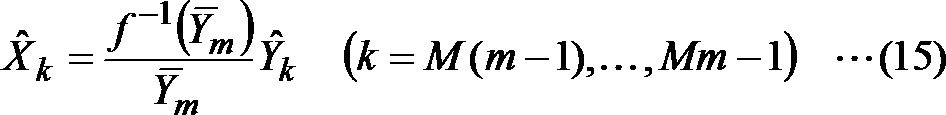
ここでは、最初に逆関数f-1(y)を用いて圧伸代表値-Ymを変換し、その関数値に応じた重みf-1(-Ym)/-Ymとサンプル値^Ykとを乗算することで出力信号^Xkに変形するといった、二段階の演算を行う例を示した。しかしながら、この発明はこのような計算方法に限定されるものではなく、信号圧伸部120と同様に、どのような計算方法を行ってもよい。例えば式(15)の演算を一段階で行うような計算を行ってもよい。
Here, first using an inverse function f -1 (y) companding representative value - to convert the Y m, the weight f -1 corresponding to the function value (- Y m) / - Y m and the sample value ^ An example of performing a two-stage operation, such as transforming to output signal ^ X k by multiplying with Y k , was shown. However, the present invention is not limited to such a calculation method, and any calculation method may be performed similarly to the signal companding unit 120. For example, a calculation that performs the calculation of Equation (15) in one step may be performed.
図17~20に、第一実施形態の復号方法の後処理により、復号重み付信号が変形される過程の具体例を示す。図17は復号方法により得られた復号重み付信号^Ykの信号波形である。横軸は時間を表し、縦軸は振幅を表す。図17の例では、0秒から2秒までの復号重み付信号^Ykを示している。図18は圧伸代表値を算出するために図17中の点線で区切られた位置で切り出したMサンプルによる区間の復号重み付信号の信号波形である。図18に示した1.28秒~1.36秒の区間に含まれるMサンプルから圧伸代表値を算出する。図19は圧伸関数の逆関数による圧伸代表値の関数値に応じて重み付けした後のMサンプルによる区間の出力信号の信号波形である。図18と比較して、波形の形状は変わらずに振幅の値が変換されていることがわかる。図20は最終的に信号後処理部から出力される出力信号^Xkの信号波形である。図17と比較して、全体として逆圧伸されていることがわかる。
17 to 20 show specific examples of the process in which the decoding weighted signal is transformed by the post-processing of the decoding method of the first embodiment. FIG. 17 shows a signal waveform of the decoding weighted signal ^ Yk obtained by the decoding method. The horizontal axis represents time, and the vertical axis represents amplitude. In the example of FIG. 17, the decoding weighted signal ^ Y k from 0 second to 2 seconds is shown. FIG. 18 is a signal waveform of a decoding weighted signal in a section of M samples cut out at positions separated by dotted lines in FIG. 17 in order to calculate a companding representative value. A companding representative value is calculated from the M samples included in the section of 1.28 seconds to 1.36 seconds shown in FIG. FIG. 19 shows the signal waveform of the output signal in the section of M samples after weighting according to the function value of the companding representative value by the inverse function of the companding function. Compared to FIG. 18, it can be seen that the amplitude value is converted without changing the shape of the waveform. FIG. 20 shows the signal waveform of the output signal ^ X k that is finally output from the signal post-processing section. Compared with FIG. 17, it turns out that it is reverse-drawn as a whole.
<第二実施形態>
第一実施形態の信号前処理部10および信号後処理部25は、時間領域の信号で準瞬時圧伸の処理を行ったが、準瞬時圧伸による信号の重み付けは周波数領域で行っても聴覚的に量子化歪みを低減することができる。第二実施形態の符号化装置3および復号装置4では、信号前処理部および信号後処理部の処理を周波数領域で行う。 <Second embodiment>
Thesignal pre-processing unit 10 and the signal post-processing unit 25 of the first embodiment perform the quasi-instantaneous companding process with the time domain signal, but the signal weighting by the quasi-instantaneous companding is performed even in the frequency domain. In particular, quantization distortion can be reduced. In the encoding device 3 and the decoding device 4 of the second embodiment, the signal preprocessing unit and the signal postprocessing unit are processed in the frequency domain.
第一実施形態の信号前処理部10および信号後処理部25は、時間領域の信号で準瞬時圧伸の処理を行ったが、準瞬時圧伸による信号の重み付けは周波数領域で行っても聴覚的に量子化歪みを低減することができる。第二実施形態の符号化装置3および復号装置4では、信号前処理部および信号後処理部の処理を周波数領域で行う。 <Second embodiment>
The
第二実施形態の符号化装置3は、図5に示すように、信号前処理部11、量子化部17、可逆符号化部18、および多重化部19を含む。つまり、第一実施形態の符号化装置1と比較して、信号前処理部の処理が異なる。第二実施形態の復号装置4は、多重分離部21、可逆復号部22、逆量子化部23、および信号後処理部26を含む。つまり、第一実施形態の復号装置2と比較して、信号後処理部の処理が異なる。
The encoding device 3 of the second embodiment includes a signal preprocessing unit 11, a quantization unit 17, a lossless encoding unit 18, and a multiplexing unit 19, as shown in FIG. That is, the processing of the signal preprocessing unit is different from that of the encoding device 1 of the first embodiment. The decoding device 4 according to the second embodiment includes a demultiplexing unit 21, a lossless decoding unit 22, an inverse quantization unit 23, and a signal post-processing unit 26. That is, the signal post-processing unit is different from the decoding device 2 of the first embodiment.
信号前処理部11は、図21に示すように、周波数変換部130、準瞬時圧伸部101、および周波数逆変換部140を含む。信号後処理部26は、図22に示すように、周波数変換部280、準瞬時逆圧伸部251、および周波数逆変換部290を含む。準瞬時圧伸部101は、図23に示すように、代表値算出部111および信号圧伸部121を含む。準瞬時逆圧伸部251は、図24に示すように、圧伸代表値算出部261および信号逆圧伸部271を含む。準瞬時圧伸部101および準瞬時逆圧伸部251は、入出力が周波数スペクトルである点が、第一実施形態の準瞬時圧伸部100および準瞬時逆圧伸部250と異なる点である。
As shown in FIG. 21, the signal preprocessing unit 11 includes a frequency conversion unit 130, a quasi-instantaneous companding unit 101, and a frequency inverse conversion unit 140. The signal post-processing unit 26 includes a frequency conversion unit 280, a quasi-instantaneous reverse companding unit 251, and a frequency reverse conversion unit 290, as shown in FIG. The quasi-instantaneous companding unit 101 includes a representative value calculating unit 111 and a signal companding unit 121 as shown in FIG. The quasi-instantaneous reverse companding unit 251 includes a companding representative value calculating unit 261 and a signal reverse companding unit 271 as shown in FIG. The quasi-instantaneous companding part 101 and the quasi-instantaneous counter-compressing part 251 are different from the quasi-instantaneous companding part 100 and the quasi-instantaneous inverse companding part 250 of the first embodiment in that the input / output is a frequency spectrum. .
≪符号化装置3≫
音声や音楽などの時間領域の音響信号xn(n=0, …, N-1、N(>0)は所定のフレーム内のサンプル数、nはフレーム内でのサンプル番号)がフレーム単位で符号化装置3へ入力される。符号化装置3へ入力された音響信号xnは信号前処理部11へ入力される。 <<Encoder 3 >>
Time domain acoustic signal x n (n = 0,…, N-1, N (> 0) is the number of samples in a given frame, n is the number of samples in a frame) in units of frames Input to theencoding device 3. The acoustic signal x n input to the encoding device 3 is input to the signal preprocessing unit 11.
音声や音楽などの時間領域の音響信号xn(n=0, …, N-1、N(>0)は所定のフレーム内のサンプル数、nはフレーム内でのサンプル番号)がフレーム単位で符号化装置3へ入力される。符号化装置3へ入力された音響信号xnは信号前処理部11へ入力される。 <<
Time domain acoustic signal x n (n = 0,…, N-1, N (> 0) is the number of samples in a given frame, n is the number of samples in a frame) in units of frames Input to the
[信号前処理部11]
信号前処理部11は、フレーム毎に、符号化装置3へ入力された音響信号xn(n=0, …, N-1)を受け取り、周波数変換部130、準瞬時圧伸部101、および周波数逆変換部140での処理を行い、重み付信号yn(n=0, …, N-1)を量子化部17へ出力する。 [Signal preprocessing unit 11]
Thesignal preprocessing unit 11 receives the acoustic signal x n (n = 0,..., N−1) input to the encoding device 3 for each frame, and receives the frequency conversion unit 130, the quasi-instantaneous companding unit 101, and The processing in the frequency inverse transform unit 140 is performed, and the weighted signal y n (n = 0,..., N−1) is output to the quantization unit 17.
信号前処理部11は、フレーム毎に、符号化装置3へ入力された音響信号xn(n=0, …, N-1)を受け取り、周波数変換部130、準瞬時圧伸部101、および周波数逆変換部140での処理を行い、重み付信号yn(n=0, …, N-1)を量子化部17へ出力する。 [Signal preprocessing unit 11]
The
[周波数変換部130]
周波数変換部130は、フレーム毎に、信号前処理部11から入力された音響信号xn(n=0, …, N-1)を受け取り、例えば以下のような離散コサイン変換を施して周波数スペクトルXk(k=0, …, N-1)に変換し、その周波数スペクトルXkを準瞬時圧伸部101へ出力する。 [Frequency conversion unit 130]
Thefrequency conversion unit 130 receives the acoustic signal x n (n = 0,..., N−1) input from the signal preprocessing unit 11 for each frame and performs, for example, the following discrete cosine transform to obtain a frequency spectrum. X k (k = 0,..., N−1) is converted and the frequency spectrum X k is output to the quasi-instantaneous companding unit 101.
周波数変換部130は、フレーム毎に、信号前処理部11から入力された音響信号xn(n=0, …, N-1)を受け取り、例えば以下のような離散コサイン変換を施して周波数スペクトルXk(k=0, …, N-1)に変換し、その周波数スペクトルXkを準瞬時圧伸部101へ出力する。 [Frequency conversion unit 130]
The

ただし、xn(n=0, …, N-1)は音響信号のサンプル値を、Xk(k=0, …, N-1)は周波数スペクトルのサンプル値をそれぞれ表す。
Here, x n (n = 0,..., N−1) represents the sample value of the acoustic signal, and X k (k = 0,..., N−1) represents the sample value of the frequency spectrum.
[準瞬時圧伸部101]
準瞬時圧伸部101は、フレーム毎に、周波数変換部130が出力した周波数スペクトルXk(k=0, …, N-1)を受け取り、代表値算出部111および信号圧伸部121での処理を行い、重み付周波数スペクトルYk(k=0, …, N-1)を周波数逆変換部140へ出力する。代表値算出部111および信号圧伸部121の処理は、第一実施形態の音響信号Xk(k=0, …, N-1)に代えて周波数スペクトルXk(k=0, …, N-1)を用い、第一実施形態の重み付信号Yk(k=0, …, N-1)に代えて重み付周波数スペクトルYk(k=0, …, N-1)を得ること以外は、第一実施形態の代表値算出部110および信号圧伸部120と同様である。 [Quasi-instantaneous stretched part 101]
Thequasi-instantaneous companding unit 101 receives the frequency spectrum X k (k = 0,..., N−1) output from the frequency converting unit 130 for each frame, and the representative value calculating unit 111 and the signal companding unit 121 Processing is performed, and the weighted frequency spectrum Y k (k = 0,..., N−1) is output to the frequency inverse transform unit 140. The processing of the representative value calculation unit 111 and the signal companding unit 121 is performed by replacing the acoustic signal X k (k = 0,..., N−1) of the first embodiment with a frequency spectrum X k (k = 0,. -1) to obtain a weighted frequency spectrum Y k (k = 0, ..., N-1) instead of the weighted signal Y k (k = 0, ..., N-1) of the first embodiment. Except for this, it is the same as the representative value calculation unit 110 and the signal companding unit 120 of the first embodiment.
準瞬時圧伸部101は、フレーム毎に、周波数変換部130が出力した周波数スペクトルXk(k=0, …, N-1)を受け取り、代表値算出部111および信号圧伸部121での処理を行い、重み付周波数スペクトルYk(k=0, …, N-1)を周波数逆変換部140へ出力する。代表値算出部111および信号圧伸部121の処理は、第一実施形態の音響信号Xk(k=0, …, N-1)に代えて周波数スペクトルXk(k=0, …, N-1)を用い、第一実施形態の重み付信号Yk(k=0, …, N-1)に代えて重み付周波数スペクトルYk(k=0, …, N-1)を得ること以外は、第一実施形態の代表値算出部110および信号圧伸部120と同様である。 [Quasi-instantaneous stretched part 101]
The
[周波数逆変換部140]
周波数逆変換部140は、フレーム毎に、準瞬時圧伸部101が出力した重み付周波数スペクトルYk(k=0, …, N-1)を受け取り、例えば以下のような逆離散コサイン変換を施して重み付信号yn(n=0, …, N-1)に変換し、その重み付信号ynを量子化部17へ出力する。 [Inverse frequency conversion unit 140]
The frequencyinverse transform unit 140 receives the weighted frequency spectrum Y k (k = 0,..., N−1) output from the quasi-instantaneous companding unit 101 for each frame and performs, for example, the following inverse discrete cosine transform. The weighted signal y n (n = 0,..., N−1) is converted, and the weighted signal y n is output to the quantization unit 17.
周波数逆変換部140は、フレーム毎に、準瞬時圧伸部101が出力した重み付周波数スペクトルYk(k=0, …, N-1)を受け取り、例えば以下のような逆離散コサイン変換を施して重み付信号yn(n=0, …, N-1)に変換し、その重み付信号ynを量子化部17へ出力する。 [Inverse frequency conversion unit 140]
The frequency

ただし、yn(n=0, …, N-1)は重み付信号のサンプル値を表す。
However, y n (n = 0,..., N−1) represents a sample value of the weighted signal.
第二実施形態の重み付信号yn(n=0, …, N-1)は、表記は第一実施形態の重み付信号Yk(k=0, …, N-1)とは異なるが、第一実施形態と同様に時間領域の重み付信号である。したがって、第二実施形態の量子化部17以降は第一実施形態と同じ動作をするので、説明を省略する。
Although the weighted signal y n (n = 0,..., N−1) of the second embodiment is different from the weighted signal Y k (k = 0,..., N−1) of the first embodiment, Similar to the first embodiment, it is a time domain weighted signal. Therefore, since the quantization unit 17 and subsequent parts of the second embodiment perform the same operation as that of the first embodiment, description thereof is omitted.
≪復号装置4≫
[信号後処理部26]
信号後処理部26は、フレーム毎に、逆量子化部23が出力した復号重み付信号^yn(n=0, …, N-1)を受け取り、周波数変換部280、準瞬時逆圧伸部251、および周波数逆変換部290での処理を行い、出力信号^xn(n=0, …, N-1)を出力する。第二実施形態の復号重み付信号^yn(n=0, …, N-1)は、表記は異なるが、第一実施形態の復号重み付信号^Yk(k=0, …, N-1)と同様に、逆量子化部23が出力した時間領域の復号重み付信号である。 << Decoding Device 4 >>
[Signal post-processing unit 26]
Thesignal post-processing unit 26 receives the decoding weighted signal ^ y n (n = 0,..., N−1) output from the inverse quantization unit 23 for each frame, and receives the frequency conversion unit 280 and the quasi-instantaneous inverse companding. Unit 251 and frequency inverse transform unit 290 perform processing, and output signal ^ x n (n = 0,..., N−1) is output. The decoding weighted signal ^ y n (n = 0,..., N-1) of the second embodiment has a different notation, but the decoding weighted signal ^ Y k (k = 0,..., N of the first embodiment is different. Similar to (-1), it is a decoding weighted signal in the time domain output from the inverse quantization unit 23.
[信号後処理部26]
信号後処理部26は、フレーム毎に、逆量子化部23が出力した復号重み付信号^yn(n=0, …, N-1)を受け取り、周波数変換部280、準瞬時逆圧伸部251、および周波数逆変換部290での処理を行い、出力信号^xn(n=0, …, N-1)を出力する。第二実施形態の復号重み付信号^yn(n=0, …, N-1)は、表記は異なるが、第一実施形態の復号重み付信号^Yk(k=0, …, N-1)と同様に、逆量子化部23が出力した時間領域の復号重み付信号である。 << Decoding Device 4 >>
[Signal post-processing unit 26]
The
[周波数変換部280]
周波数変換部280は、フレーム毎に、信号後処理部26から入力された復号重み付信号^yn(n=0, …, N-1)を受け取り、周波数変換部130と同様にして、復号重み付周波数スペクトル^Yk(k=0, …, N-1)に変換し、その復号重み付周波数スペクトル^Ykを準瞬時逆圧伸部251へ出力する。 [Frequency converter 280]
Thefrequency conversion unit 280 receives the decoding weighted signal ^ y n (n = 0,..., N−1) input from the signal post-processing unit 26 for each frame, and performs decoding in the same manner as the frequency conversion unit 130. The weighted frequency spectrum ^ Y k (k = 0,..., N−1) is converted and the decoded weighted frequency spectrum ^ Y k is output to the quasi-instantaneous reverse companding unit 251.
周波数変換部280は、フレーム毎に、信号後処理部26から入力された復号重み付信号^yn(n=0, …, N-1)を受け取り、周波数変換部130と同様にして、復号重み付周波数スペクトル^Yk(k=0, …, N-1)に変換し、その復号重み付周波数スペクトル^Ykを準瞬時逆圧伸部251へ出力する。 [Frequency converter 280]
The
[準瞬時逆圧伸部251]
準瞬時逆圧伸部251は、フレーム毎に、周波数変換部280が出力した復号重み付周波数スペクトル^Yk(k=0, …, N-1)を受け取り、圧伸代表値算出部261および信号逆圧伸部271での処理を行い、復号周波数スペクトル^Xk(k=0, …, N-1)を周波数逆変換部290へ出力する。圧伸代表値算出部261および信号逆圧伸部271の処理は、第一実施形態の復号重み付信号^Yk(k=0, …, N-1)に代えて復号重み付周波数スペクトル^Yk(k=0, …, N-1)を用い、第一実施形態の出力信号^Xk(k=0, …, N-1)に代えて復号周波数スペクトル^Xk(k=0, …, N-1)を得ること以外は、第一実施形態の圧伸代表値算出部260および信号逆圧伸部270と同様である。 [Quasi-instantaneous reverse companding section 251]
The quasi-instantaneousreverse companding unit 251 receives the decoding weighted frequency spectrum ^ Y k (k = 0,..., N−1) output from the frequency converting unit 280 for each frame, and receives the companding representative value calculating unit 261 and The signal inverse companding unit 271 performs processing, and outputs the decoded frequency spectrum ^ X k (k = 0,..., N−1) to the frequency inverse transform unit 290. The processing of the companding representative value calculation unit 261 and the signal reverse companding unit 271 is performed by using the decoding weighted frequency spectrum instead of the decoding weighted signal ^ Y k (k = 0,..., N−1) of the first embodiment ^ Using Y k (k = 0,…, N−1), instead of the output signal ^ X k (k = 0,…, N−1) of the first embodiment, the decoded frequency spectrum ^ X k (k = 0) ,..., N-1) is the same as the companding representative value calculating unit 260 and the signal counter companding unit 270 of the first embodiment.
準瞬時逆圧伸部251は、フレーム毎に、周波数変換部280が出力した復号重み付周波数スペクトル^Yk(k=0, …, N-1)を受け取り、圧伸代表値算出部261および信号逆圧伸部271での処理を行い、復号周波数スペクトル^Xk(k=0, …, N-1)を周波数逆変換部290へ出力する。圧伸代表値算出部261および信号逆圧伸部271の処理は、第一実施形態の復号重み付信号^Yk(k=0, …, N-1)に代えて復号重み付周波数スペクトル^Yk(k=0, …, N-1)を用い、第一実施形態の出力信号^Xk(k=0, …, N-1)に代えて復号周波数スペクトル^Xk(k=0, …, N-1)を得ること以外は、第一実施形態の圧伸代表値算出部260および信号逆圧伸部270と同様である。 [Quasi-instantaneous reverse companding section 251]
The quasi-instantaneous
[周波数逆変換部290]
周波数逆変換部290は、フレーム毎に、準瞬時逆圧伸部251が出力した復号周波数スペクトル^Xk(k=0, …, N-1)を受け取り、周波数逆変換部140と同様にして、出力信号^xn(n=0, …, N-1)に変換し、その出力信号^xnを出力する。 [Inverse frequency conversion unit 290]
The frequencyinverse transform unit 290 receives the decoded frequency spectrum ^ X k (k = 0,..., N−1) output from the quasi-instantaneous reverse companding unit 251 for each frame, and performs the same process as the frequency inverse transform unit 140. The output signal ^ x n (n = 0,..., N−1) is converted and the output signal ^ x n is output.
周波数逆変換部290は、フレーム毎に、準瞬時逆圧伸部251が出力した復号周波数スペクトル^Xk(k=0, …, N-1)を受け取り、周波数逆変換部140と同様にして、出力信号^xn(n=0, …, N-1)に変換し、その出力信号^xnを出力する。 [Inverse frequency conversion unit 290]
The frequency
<第三実施形態>
第二実施形態の信号前処理部11および信号後処理部26は、周波数領域にて準瞬時圧伸を行った後、時間領域に戻して符号化および復号の処理を行った。第三実施形態では、時間領域に戻さず周波数領域のまま符号化および復号の処理を行う。 <Third embodiment>
Thesignal preprocessing unit 11 and the signal postprocessing unit 26 of the second embodiment performed quasi-instantaneous companding in the frequency domain, and then returned to the time domain to perform encoding and decoding processing. In the third embodiment, encoding and decoding processes are performed in the frequency domain without returning to the time domain.
第二実施形態の信号前処理部11および信号後処理部26は、周波数領域にて準瞬時圧伸を行った後、時間領域に戻して符号化および復号の処理を行った。第三実施形態では、時間領域に戻さず周波数領域のまま符号化および復号の処理を行う。 <Third embodiment>
The
第三実施形態の符号化装置5は、図25に示すように、信号前処理部12、量子化部17、可逆符号化部18、および多重化部19を含む。つまり、第二実施形態の符号化装置3と比較して、信号前処理部の処理が異なる。第三実施形態の復号装置6は、図26に示すように、多重分離部21、可逆復号部22、逆量子化部23、および信号後処理部27を含む。つまり、第二実施形態の復号装置4と比較して、信号後処理部の処理が異なる。
As shown in FIG. 25, the encoding device 5 of the third embodiment includes a signal preprocessing unit 12, a quantization unit 17, a lossless encoding unit 18, and a multiplexing unit 19. That is, the processing of the signal preprocessing unit is different from that of the encoding device 3 of the second embodiment. As illustrated in FIG. 26, the decoding device 6 according to the third embodiment includes a demultiplexing unit 21, a lossless decoding unit 22, an inverse quantization unit 23, and a signal post-processing unit 27. That is, the signal post-processing unit is different from the decoding device 4 of the second embodiment.
信号前処理部12は、図27に示すように、周波数変換部130および準瞬時圧伸部101を含む。つまり、第二実施形態の信号前処理部11と比較して、周波数逆変換部140を含まず、重み付周波数スペクトルを出力する点が異なる。信号後処理部27は、図28に示すように、準瞬時逆圧伸部251および周波数逆変換部290を含む。つまり、第二実施形態の信号後処理部26と比較して、周波数変換部280を含まず、復号重み付周波数スペクトルが入力される点が異なる。量子化部17、可逆符号化部18、可逆復号部22および逆量子化部23は、第二実施形態の量子化部17、可逆符号化部18、可逆復号部22および逆量子化部23と同様の処理を行うが、時間領域の信号に代えて周波数スペクトルを扱う点が第二実施形態とは異なる。
The signal preprocessing unit 12 includes a frequency conversion unit 130 and a quasi-instantaneous companding unit 101 as shown in FIG. That is, it differs from the signal preprocessing unit 11 of the second embodiment in that the frequency inverse transform unit 140 is not included and a weighted frequency spectrum is output. As shown in FIG. 28, the signal post-processing unit 27 includes a quasi-instantaneous reverse companding unit 251 and a frequency inverse converting unit 290. That is, it differs from the signal post-processing unit 26 of the second embodiment in that the frequency conversion unit 280 is not included and a decoding weighted frequency spectrum is input. The quantization unit 17, the lossless encoding unit 18, the lossless decoding unit 22, and the inverse quantization unit 23 are the same as the quantization unit 17, the lossless encoding unit 18, the lossless decoding unit 22, and the inverse quantization unit 23 of the second embodiment. Although the same processing is performed, it is different from the second embodiment in that a frequency spectrum is handled instead of the time domain signal.
≪符号化装置5≫
[信号前処理部12]
信号前処理部12は、フレーム毎に、符号化装置5へ入力された音響信号xn(n=0, …, N-1)を受け取り、周波数変換部130および準瞬時圧伸部101での処理を行い、重み付周波数スペクトルYk(k=0, …, N-1)を量子化部17へ出力する。周波数変換部130および準瞬時圧伸部101の処理は、上述の第二実施形態と同様である。 <<Encoder 5 >>
[Signal preprocessing unit 12]
Thesignal preprocessing unit 12 receives the acoustic signal x n (n = 0,..., N−1) input to the encoding device 5 for each frame, and the frequency conversion unit 130 and the quasi-instantaneous companding unit 101 Processing is performed, and the weighted frequency spectrum Y k (k = 0,..., N−1) is output to the quantization unit 17. The processing of the frequency conversion unit 130 and the quasi-instantaneous companding unit 101 is the same as that in the second embodiment described above.
[信号前処理部12]
信号前処理部12は、フレーム毎に、符号化装置5へ入力された音響信号xn(n=0, …, N-1)を受け取り、周波数変換部130および準瞬時圧伸部101での処理を行い、重み付周波数スペクトルYk(k=0, …, N-1)を量子化部17へ出力する。周波数変換部130および準瞬時圧伸部101の処理は、上述の第二実施形態と同様である。 <<
[Signal preprocessing unit 12]
The
第三実施形態の重み付周波数スペクトルYk(k=0, …, N-1)は周波数領域の信号であり、第二実施形態の重み付信号Yk(k=0, …, N-1)は時間領域の信号であるが、量子化部17以降は、信号が時間領域であっても周波数領域であっても同様の動作をするので、説明を省略する。
The weighted frequency spectrum Y k (k = 0,..., N−1) of the third embodiment is a frequency domain signal, and the weighted signal Y k (k = 0,..., N−1) of the second embodiment. ) Is a signal in the time domain, and the quantizing unit 17 and later perform the same operation regardless of whether the signal is in the time domain or the frequency domain, and thus the description thereof is omitted.
≪復号装置6≫
[可逆復号部22]
可逆復号部22は、多重分離部21が出力した信号符号を受け取り、可逆符号化部18の処理に対応する可逆復号を行い、信号符号に対応する周波数スペクトルを復号量子化周波数スペクトルとして逆量子化部23へ出力する。 << Decoding Device 6 >>
[Reversible decoding unit 22]
Thelossless decoding unit 22 receives the signal code output from the demultiplexing unit 21, performs lossless decoding corresponding to the processing of the lossless encoding unit 18, and dequantizes the frequency spectrum corresponding to the signal code as a decoded quantized frequency spectrum. To the unit 23.
[可逆復号部22]
可逆復号部22は、多重分離部21が出力した信号符号を受け取り、可逆符号化部18の処理に対応する可逆復号を行い、信号符号に対応する周波数スペクトルを復号量子化周波数スペクトルとして逆量子化部23へ出力する。 << Decoding Device 6 >>
[Reversible decoding unit 22]
The
[逆量子化部23]
逆量子化部23は、可逆復号部22が出力した復号量子化周波数スペクトルと、多重分離部21が出力した量子化幅とを受け取り、例えば従来技術と同様に、量子化幅に対応する値と復号量子化周波数スペクトルの各サンプル値とをサンプル毎に乗算し、逆量子化された信号を得る。逆量子化部23は、逆量子化された信号をサンプル数Nのフレーム毎の復号重み付周波数スペクトル^Yk(k=0, …, N-1)として信号後処理部27へ出力する。 [Inverse quantization unit 23]
Theinverse quantization unit 23 receives the decoded quantized frequency spectrum output from the lossless decoding unit 22 and the quantization width output from the demultiplexing unit 21, and, for example, in the same manner as in the prior art, a value corresponding to the quantization width and Each sample value of the decoded quantized frequency spectrum is multiplied for each sample to obtain a dequantized signal. The inverse quantization unit 23 outputs the inversely quantized signal to the signal post-processing unit 27 as a decoding weighted frequency spectrum ^ Y k (k = 0,..., N−1) for each frame of N samples.
逆量子化部23は、可逆復号部22が出力した復号量子化周波数スペクトルと、多重分離部21が出力した量子化幅とを受け取り、例えば従来技術と同様に、量子化幅に対応する値と復号量子化周波数スペクトルの各サンプル値とをサンプル毎に乗算し、逆量子化された信号を得る。逆量子化部23は、逆量子化された信号をサンプル数Nのフレーム毎の復号重み付周波数スペクトル^Yk(k=0, …, N-1)として信号後処理部27へ出力する。 [Inverse quantization unit 23]
The
[信号後処理部27]
信号後処理部27は、フレーム毎に、逆量子化部23が出力した復号重み付周波数スペクトル^Yk(k=0, …, N-1)を受け取り、準瞬時逆圧伸部251および周波数逆変換部290での処理を行い、出力信号^xn(n=0, …, N-1)を出力する。準瞬時逆圧伸部251および周波数逆変換部290の処理は、上述の第二実施形態と同様である。 [Signal post-processing unit 27]
Thesignal post-processing unit 27 receives the decoding weighted frequency spectrum ^ Y k (k = 0,..., N−1) output from the inverse quantization unit 23 for each frame, and receives the quasi-instantaneous inverse companding unit 251 and the frequency. The inverse conversion unit 290 performs processing and outputs an output signal ^ x n (n = 0,..., N−1). The processes of the quasi-instantaneous reverse companding unit 251 and the frequency reverse converting unit 290 are the same as those in the second embodiment described above.
信号後処理部27は、フレーム毎に、逆量子化部23が出力した復号重み付周波数スペクトル^Yk(k=0, …, N-1)を受け取り、準瞬時逆圧伸部251および周波数逆変換部290での処理を行い、出力信号^xn(n=0, …, N-1)を出力する。準瞬時逆圧伸部251および周波数逆変換部290の処理は、上述の第二実施形態と同様である。 [Signal post-processing unit 27]
The
<第四実施形態>
第一実施形態の信号前処理部10および信号後処理部25は、時間領域の信号で準瞬時圧伸の処理を行った後、時間領域のまま符号化および復号の処理を行った。第四実施形態では、時間領域の信号で準瞬時圧伸の処理を行った後、周波数領域に変換して符号化および復号の処理を行う。 <Fourth embodiment>
Thesignal preprocessing unit 10 and the signal postprocessing unit 25 of the first embodiment performed the quasi-instantaneous companding process on the time domain signal, and then performed the encoding and decoding processes in the time domain. In the fourth embodiment, the quasi-instantaneous companding process is performed with the time domain signal, and then the signal is converted into the frequency domain to be encoded and decoded.
第一実施形態の信号前処理部10および信号後処理部25は、時間領域の信号で準瞬時圧伸の処理を行った後、時間領域のまま符号化および復号の処理を行った。第四実施形態では、時間領域の信号で準瞬時圧伸の処理を行った後、周波数領域に変換して符号化および復号の処理を行う。 <Fourth embodiment>
The
第四実施形態の符号化装置7は、図25に示すように、信号前処理部13、量子化部17、可逆符号化部18、および多重化部19を含む。つまり、第一実施形態の符号化装置1と比較して、信号前処理部の処理が異なる。第四実施形態の復号装置8は、図26に示すように、多重分離部21、可逆復号部22、逆量子化部23、および信号後処理部28を含む。つまり、第一実施形態の復号装置2と比較して、信号後処理部の処理が異なる。
The encoding device 7 according to the fourth embodiment includes a signal preprocessing unit 13, a quantization unit 17, a lossless encoding unit 18, and a multiplexing unit 19, as shown in FIG. That is, the processing of the signal preprocessing unit is different from that of the encoding device 1 of the first embodiment. As shown in FIG. 26, the decoding device 8 of the fourth embodiment includes a demultiplexing unit 21, a lossless decoding unit 22, an inverse quantization unit 23, and a signal post-processing unit 28. That is, the signal post-processing unit is different from the decoding device 2 of the first embodiment.
信号前処理部13は、図29に示すように、準瞬時圧伸部100および周波数変換部130を含む。つまり、第一実施形態の信号前処理部10と比較して、準瞬時圧伸部100の後段に周波数変換部130を接続し、重み付周波数スペクトルを出力する点が異なる。信号後処理部28は、図30に示すように、周波数逆変換部290および準瞬時逆圧伸部250を含む。つまり、第一実施形態の信号後処理部25と比較して、準瞬時逆圧伸部250の前段に周波数逆変換部290を接続し、復号重み付周波数スペクトルが入力される点が異なる。量子化部17、可逆符号化部18、可逆復号部22および逆量子化部23は、第一実施形態の量子化部17、可逆符号化部18、可逆復号部22および逆量子化部23と同様の処理を行うが、時間領域の信号に代えて周波数スペクトルを扱う点が第一実施形態とは異なる。
The signal pre-processing unit 13 includes a quasi-instantaneous companding unit 100 and a frequency converting unit 130 as shown in FIG. That is, as compared with the signal preprocessing unit 10 of the first embodiment, the frequency converter 130 is connected to the subsequent stage of the quasi-instantaneous companding unit 100 and a weighted frequency spectrum is output. The signal post-processing unit 28 includes a frequency reverse conversion unit 290 and a quasi instantaneous reverse companding unit 250, as shown in FIG. That is, the difference from the signal post-processing unit 25 of the first embodiment is that the frequency inverse transform unit 290 is connected to the preceding stage of the quasi-instantaneous reverse companding unit 250 and the decoded weighted frequency spectrum is input. The quantization unit 17, the lossless encoding unit 18, the lossless decoding unit 22, and the inverse quantization unit 23 are the same as the quantization unit 17, the lossless encoding unit 18, the lossless decoding unit 22, and the inverse quantization unit 23 of the first embodiment. Although the same processing is performed, it is different from the first embodiment in that a frequency spectrum is handled instead of the time domain signal.
≪符号化装置7≫
音声や音楽などの時間領域の音響信号xn(n=0, …, N-1、N(>0)は所定のフレーム内のサンプル数、nはフレーム内でのサンプル番号)がフレーム単位で符号化装置7へ入力される。符号化装置7へ入力された音響信号xnは信号前処理部13へ入力される。 << Encoder 7 >>
Time domain acoustic signal x n (n = 0,…, N-1, N (> 0) is the number of samples in a given frame, n is the number of samples in a frame) in units of frames Input to the encoding device 7. The acoustic signal x n input to the encoding device 7 is input to thesignal preprocessing unit 13.
音声や音楽などの時間領域の音響信号xn(n=0, …, N-1、N(>0)は所定のフレーム内のサンプル数、nはフレーム内でのサンプル番号)がフレーム単位で符号化装置7へ入力される。符号化装置7へ入力された音響信号xnは信号前処理部13へ入力される。 << Encoder 7 >>
Time domain acoustic signal x n (n = 0,…, N-1, N (> 0) is the number of samples in a given frame, n is the number of samples in a frame) in units of frames Input to the encoding device 7. The acoustic signal x n input to the encoding device 7 is input to the
[信号前処理部13]
信号前処理部13は、フレーム毎に、符号化装置7へ入力された音響信号xn(n=0, …, N-1)を受け取り、準瞬時圧伸部100および周波数変換部130での処理を行い、重み付周波数スペクトルYk(k=0, …, N-1)を量子化部17へ出力する。 [Signal preprocessing unit 13]
Thesignal preprocessing unit 13 receives the acoustic signal x n (n = 0,..., N−1) input to the encoding device 7 for each frame, and the quasi instantaneous companding unit 100 and the frequency converting unit 130 Processing is performed, and the weighted frequency spectrum Y k (k = 0,..., N−1) is output to the quantization unit 17.
信号前処理部13は、フレーム毎に、符号化装置7へ入力された音響信号xn(n=0, …, N-1)を受け取り、準瞬時圧伸部100および周波数変換部130での処理を行い、重み付周波数スペクトルYk(k=0, …, N-1)を量子化部17へ出力する。 [Signal preprocessing unit 13]
The
[準瞬時圧伸部100]
準瞬時圧伸部100は、フレーム毎に、符号化装置7へ入力された音響信号xn(n=0, …, N-1)を受け取り、代表値算出部110および信号圧伸部120での処理を行い、重み付信号yn(n=0, …, N-1)を周波数変換部130へ出力する。準瞬時圧伸部100の処理は、音響信号xn(n=0, …, N-1)が上述の第一実施形態では音響信号Xk(k=0, …, N-1)と表記され、重み付信号yn(n=0, …, N-1)が上述の第一実施形態では重み付信号Yk(k=0, …, N-1)と表記されていること以外は、上述の第一実施形態と同様である。 [Quasi-instantaneous stretched part 100]
Thequasi-instantaneous companding unit 100 receives the acoustic signal x n (n = 0,..., N−1) input to the encoding device 7 for each frame, and the representative value calculating unit 110 and the signal companding unit 120 The weighted signal y n (n = 0,..., N−1) is output to the frequency conversion unit 130. In the processing of the quasi-instantaneous companding unit 100, the acoustic signal x n (n = 0,..., N−1) is expressed as the acoustic signal X k (k = 0,..., N−1) in the first embodiment described above. Except that the weighted signal y n (n = 0,..., N−1) is expressed as the weighted signal Y k (k = 0,..., N−1) in the first embodiment described above. This is the same as the first embodiment described above.
準瞬時圧伸部100は、フレーム毎に、符号化装置7へ入力された音響信号xn(n=0, …, N-1)を受け取り、代表値算出部110および信号圧伸部120での処理を行い、重み付信号yn(n=0, …, N-1)を周波数変換部130へ出力する。準瞬時圧伸部100の処理は、音響信号xn(n=0, …, N-1)が上述の第一実施形態では音響信号Xk(k=0, …, N-1)と表記され、重み付信号yn(n=0, …, N-1)が上述の第一実施形態では重み付信号Yk(k=0, …, N-1)と表記されていること以外は、上述の第一実施形態と同様である。 [Quasi-instantaneous stretched part 100]
The
[周波数変換部130]
周波数変換部130は、フレーム毎に、準瞬時圧伸部100から入力された重み付信号yn(n=0, …, N-1)を受け取り、周波数領域のスペクトルに変換して、重み付周波数スペクトルYk(k=0, …, N-1)を得て、量子化部17へ出力する。周波数変換部130の処理は、上述の第二実施形態と同様である。 [Frequency conversion unit 130]
Thefrequency conversion unit 130 receives the weighted signal y n (n = 0,..., N−1) input from the quasi-instantaneous companding unit 100 for each frame, converts it into a frequency domain spectrum, and weights it. A frequency spectrum Y k (k = 0,..., N−1) is obtained and output to the quantization unit 17. The processing of the frequency conversion unit 130 is the same as that in the second embodiment described above.
周波数変換部130は、フレーム毎に、準瞬時圧伸部100から入力された重み付信号yn(n=0, …, N-1)を受け取り、周波数領域のスペクトルに変換して、重み付周波数スペクトルYk(k=0, …, N-1)を得て、量子化部17へ出力する。周波数変換部130の処理は、上述の第二実施形態と同様である。 [Frequency conversion unit 130]
The
第四実施形態の重み付周波数スペクトルYk(k=0, …, N-1)は周波数領域の信号であり、第一実施形態の重み付信号Yk(k=0, …, N-1)は時間領域の信号であるが、量子化部17以降は、信号が時間領域であっても周波数領域であっても同様の動作をするので、説明を省略する。
The weighted frequency spectrum Y k (k = 0,..., N−1) of the fourth embodiment is a frequency domain signal, and the weighted signal Y k (k = 0,..., N−1) of the first embodiment is used. ) Is a signal in the time domain, and the quantizing unit 17 and later perform the same operation regardless of whether the signal is in the time domain or the frequency domain, and thus the description thereof is omitted.
≪復号装置8≫
[可逆復号部22]
可逆復号部22は、多重分離部21が出力した信号符号を受け取り、可逆符号化部18の処理に対応する可逆復号を行い、信号符号に対応する周波数スペクトルを復号量子化周波数スペクトルとして逆量子化部23へ出力する。 << Decoding device 8 >>
[Reversible decoding unit 22]
Thelossless decoding unit 22 receives the signal code output from the demultiplexing unit 21, performs lossless decoding corresponding to the processing of the lossless encoding unit 18, and dequantizes the frequency spectrum corresponding to the signal code as a decoded quantized frequency spectrum. To the unit 23.
[可逆復号部22]
可逆復号部22は、多重分離部21が出力した信号符号を受け取り、可逆符号化部18の処理に対応する可逆復号を行い、信号符号に対応する周波数スペクトルを復号量子化周波数スペクトルとして逆量子化部23へ出力する。 << Decoding device 8 >>
[Reversible decoding unit 22]
The
[逆量子化部23]
逆量子化部23は、可逆復号部22が出力した復号量子化周波数スペクトルと、多重分離部21が出力した量子化幅とを受け取り、例えば従来技術と同様に、量子化幅に対応する値と復号量子化周波数スペクトルの各サンプル値とをサンプル毎に乗算し、逆量子化された信号を得る。逆量子化部23は、逆量子化された信号を復号重み付周波数スペクトル^Yk(k=0, …, N-1)として信号後処理部28へ出力する。 [Inverse quantization unit 23]
Theinverse quantization unit 23 receives the decoded quantized frequency spectrum output from the lossless decoding unit 22 and the quantization width output from the demultiplexing unit 21, and, for example, in the same manner as in the prior art, a value corresponding to the quantization width and Each sample value of the decoded quantized frequency spectrum is multiplied for each sample to obtain a dequantized signal. The inverse quantization unit 23 outputs the inversely quantized signal to the signal post-processing unit 28 as a decoded weighted frequency spectrum ^ Y k (k = 0,..., N−1).
逆量子化部23は、可逆復号部22が出力した復号量子化周波数スペクトルと、多重分離部21が出力した量子化幅とを受け取り、例えば従来技術と同様に、量子化幅に対応する値と復号量子化周波数スペクトルの各サンプル値とをサンプル毎に乗算し、逆量子化された信号を得る。逆量子化部23は、逆量子化された信号を復号重み付周波数スペクトル^Yk(k=0, …, N-1)として信号後処理部28へ出力する。 [Inverse quantization unit 23]
The
[信号後処理部28]
信号後処理部28は、フレーム毎に、逆量子化部23が出力した復号重み付周波数スペクトル^Yk(k=0, …, N-1)を受け取り、周波数逆変換部290および準瞬時逆圧伸部250での処理を行い、出力信号^xn(n=0, …, N-1)を出力する。 [Signal post-processing unit 28]
Thesignal post-processing unit 28 receives the decoding weighted frequency spectrum ^ Y k (k = 0,..., N−1) output from the inverse quantization unit 23 for each frame, and receives the frequency inverse transform unit 290 and the quasi-instantaneous inverse. The processing in the companding section 250 is performed, and an output signal ^ x n (n = 0,..., N−1) is output.
信号後処理部28は、フレーム毎に、逆量子化部23が出力した復号重み付周波数スペクトル^Yk(k=0, …, N-1)を受け取り、周波数逆変換部290および準瞬時逆圧伸部250での処理を行い、出力信号^xn(n=0, …, N-1)を出力する。 [Signal post-processing unit 28]
The
[周波数逆変換部290]
周波数逆変換部290は、フレーム毎に、逆量子化部23が出力した復号重み付周波数スペクトル^Yk(k=0, …, N-1)を受け取り、時間領域の信号に変換して、復号重み付信号^yn(n=0, …, N-1)を得て、準瞬時逆圧伸部250へ出力する。周波数逆変換部290の処理は、上述の第二実施形態と同様である。 [Inverse frequency conversion unit 290]
The frequencyinverse transform unit 290 receives the decoding weighted frequency spectrum ^ Y k (k = 0,..., N−1) output from the inverse quantization unit 23 for each frame, converts it into a time domain signal, and A decoding weighted signal ^ y n (n = 0,..., N−1) is obtained and output to the quasi-instantaneous reverse companding unit 250. The processing of the frequency inverse transform unit 290 is the same as that in the second embodiment described above.
周波数逆変換部290は、フレーム毎に、逆量子化部23が出力した復号重み付周波数スペクトル^Yk(k=0, …, N-1)を受け取り、時間領域の信号に変換して、復号重み付信号^yn(n=0, …, N-1)を得て、準瞬時逆圧伸部250へ出力する。周波数逆変換部290の処理は、上述の第二実施形態と同様である。 [Inverse frequency conversion unit 290]
The frequency
[準瞬時逆圧伸部250]
準瞬時逆圧伸部250は、フレーム毎に、入力された復号重み付信号^yn(n=0, …, N-1)を受け取り、圧伸代表値算出部260および信号逆圧伸部270での処理を行い、出力信号^xn(n=0, …, N-1)を出力する。準瞬時逆圧伸部250の処理は、復号重み付信号^yn(n=0, …, N-1)が上述の第一実施形態では復号重み付信号^Yk(k=0, …, N-1)と表記され、出力信号^xn(n=0, …, N-1)が上述の第一実施形態では出力信号^Xk(k=0, …, N-1)と表記されていること以外は、上述の第一実施形態と同様である。 [Quasi-instantaneous reverse companding section 250]
The quasi-instantaneousreverse companding unit 250 receives the input decoding weighted signal ^ y n (n = 0,..., N−1) for each frame, and displays the companding representative value calculating unit 260 and the signal reverse companding unit. The processing at 270 is performed, and an output signal ^ x n (n = 0,..., N−1) is output. In the processing of the quasi-instantaneous reverse companding unit 250, the decoding weighted signal ^ y n (n = 0,..., N−1) is the decoding weighted signal ^ Y k (k = 0,. , N-1) and the output signal ^ x n (n = 0,…, N-1) is the output signal ^ X k (k = 0,…, N-1) in the first embodiment described above. Except for the notation, the second embodiment is the same as the first embodiment.
準瞬時逆圧伸部250は、フレーム毎に、入力された復号重み付信号^yn(n=0, …, N-1)を受け取り、圧伸代表値算出部260および信号逆圧伸部270での処理を行い、出力信号^xn(n=0, …, N-1)を出力する。準瞬時逆圧伸部250の処理は、復号重み付信号^yn(n=0, …, N-1)が上述の第一実施形態では復号重み付信号^Yk(k=0, …, N-1)と表記され、出力信号^xn(n=0, …, N-1)が上述の第一実施形態では出力信号^Xk(k=0, …, N-1)と表記されていること以外は、上述の第一実施形態と同様である。 [Quasi-instantaneous reverse companding section 250]
The quasi-instantaneous
<第一実施形態から第四実施形態のポイント>
第一実施形態では時間領域で前処理および後処理を行い、時間領域で符号化処理および復号処理を行う構成を説明した。第二実施形態では周波数領域で前処理および後処理を行い、時間領域で符号化処理および復号処理を行う構成を説明した。第三実施形態では周波数領域で前処理および後処理を行い、周波数領域で符号化処理および復号処理を行う構成を説明した。第四実施形態では時間領域で前処理および後処理を行い、周波数領域で符号化処理および復号処理を行う構成を説明した。すなわち、この発明では、前処理および後処理と、符号化処理および復号処理は、周波数領域と時間領域の任意の組み合わせで実施することができる。言い替えると、この発明の前処理および後処理は、周波数領域の符号化処理および復号処理と時間領域の符号化処理および復号処理とのどちらに対しても適用可能なものである。 <Points from the first embodiment to the fourth embodiment>
In the first embodiment, a configuration has been described in which preprocessing and postprocessing are performed in the time domain, and encoding processing and decoding processing are performed in the time domain. In the second embodiment, a configuration has been described in which preprocessing and postprocessing are performed in the frequency domain, and encoding processing and decoding processing are performed in the time domain. In the third embodiment, a configuration has been described in which preprocessing and postprocessing are performed in the frequency domain, and encoding processing and decoding processing are performed in the frequency domain. In the fourth embodiment, a configuration has been described in which preprocessing and postprocessing are performed in the time domain, and encoding processing and decoding processing are performed in the frequency domain. That is, in the present invention, the pre-processing and post-processing, and the encoding processing and decoding processing can be performed in any combination of frequency domain and time domain. In other words, the pre-processing and post-processing of the present invention are applicable to both frequency domain encoding processing and decoding processing and time domain encoding processing and decoding processing.
<第五実施形態>
準瞬時圧伸の処理を行う複数サンプルの区間は予め決めた長さであればどのように定めても補助情報を用いずに逆変換を行うことができる。しかしながら、聴覚品質を考慮すると、準瞬時圧伸の処理を行う複数サンプルの区間をより適切に定めることができる。 <Fifth embodiment>
A plurality of sample sections for performing the quasi-instantaneous companding process can be inversely transformed without using auxiliary information, regardless of how long the section is determined in advance. However, when auditory quality is taken into consideration, it is possible to more appropriately determine a plurality of sample intervals for performing the quasi-instantaneous companding process.
人間の聴覚は各周波数の振幅を対数的に感じ取っているため、その観点ではサンプル毎に個々に重み付けした方がよい。しかしながら、ピーク周辺の周波数はピークの値に引きずられて重みが小さくなるべきであるため、その観点では複数サンプルをまとめて重み付けした方がよい。一方、人間の聴覚の周波数解像度は低周波数において高く、高周波数において低いことが知られている。そこで、第五実施形態では低周波数での処理区間を細かく、高周波数での処理区間を粗く設定することで、聴覚品質を考慮しながらより効率的な重み付けを実現する。
Since human hearing senses the amplitude of each frequency logarithmically, it is better to weight each sample individually from that viewpoint. However, since the frequency around the peak should be dragged to the peak value and the weight should be reduced, it is better to weight a plurality of samples collectively from that viewpoint. On the other hand, it is known that the frequency resolution of human hearing is high at low frequencies and low at high frequencies. Therefore, in the fifth embodiment, more efficient weighting is realized while considering auditory quality by setting the processing interval at a low frequency finely and the processing interval at a high frequency coarsely.
≪符号化装置≫
第五実施形態の符号化装置は、第二実施形態の符号化装置3もしくは第三実施形態の符号化装置5において、代表値算出部111および信号圧伸部121の処理を以下のように変更したものである。 <Encoder>
In the encoding device of the fifth embodiment, the processing of the representativevalue calculation unit 111 and the signal companding unit 121 is changed as follows in the encoding device 3 of the second embodiment or the encoding device 5 of the third embodiment. It is a thing.
第五実施形態の符号化装置は、第二実施形態の符号化装置3もしくは第三実施形態の符号化装置5において、代表値算出部111および信号圧伸部121の処理を以下のように変更したものである。 <Encoder>
In the encoding device of the fifth embodiment, the processing of the representative
[代表値算出部111]
代表値算出部111は、フレーム毎に、周波数変換部130が出力した周波数スペクトルXk(k=0, …, N-1)を受け取り、各フレームの周波数スペクトルXk(k=0, …, N-1)を予め定めた個数のサンプルを含むL個の区間(周波数区間)に分割し、その区間毎に代表値-Xm(m=1, …, L)を算出し、信号圧伸部121へ出力する。このとき、各区間に含まれるサンプル数は任意に定めることができる。例えば、K0, …, KL(0=K0<…<KL=N-1)をフレーム内のサンプルの番号を表すものとし、L個の区間を[K0 K1], [K1 K2], …, [KL-1 KL]のように定義する。[Km-1 Km]は、フレーム内の(Km-1+1)番目のサンプルからKm番目のサンプルまでをm番目の区間として定義することを表している。このとき、代表値-Xm(m=1, …, L)は、例えば絶対値平均を用いて、 [Representative value calculation unit 111]
The representativevalue calculation unit 111 receives the frequency spectrum X k (k = 0,..., N−1) output from the frequency conversion unit 130 for each frame, and the frequency spectrum X k (k = 0,. divided into L sections (frequency interval) containing a sample of N-1) predetermined number of representative values for respective sections - X m (m = 1, ..., L) is calculated, the signal companding Output to the unit 121. At this time, the number of samples included in each section can be arbitrarily determined. For example, let K 0 ,…, K L (0 = K 0 <… <K L = N−1) represent the number of samples in the frame, and let L intervals be [K 0 K 1 ], [K 1 K 2 ],…, [K L-1 K L ] [K m-1 K m ] represents that the (K m-1 +1) -th sample to the K m- th sample in the frame are defined as the m-th interval. At this time, the representative value - X m (m = 1, ..., L) , for example by using the absolute value average,
代表値算出部111は、フレーム毎に、周波数変換部130が出力した周波数スペクトルXk(k=0, …, N-1)を受け取り、各フレームの周波数スペクトルXk(k=0, …, N-1)を予め定めた個数のサンプルを含むL個の区間(周波数区間)に分割し、その区間毎に代表値-Xm(m=1, …, L)を算出し、信号圧伸部121へ出力する。このとき、各区間に含まれるサンプル数は任意に定めることができる。例えば、K0, …, KL(0=K0<…<KL=N-1)をフレーム内のサンプルの番号を表すものとし、L個の区間を[K0 K1], [K1 K2], …, [KL-1 KL]のように定義する。[Km-1 Km]は、フレーム内の(Km-1+1)番目のサンプルからKm番目のサンプルまでをm番目の区間として定義することを表している。このとき、代表値-Xm(m=1, …, L)は、例えば絶対値平均を用いて、 [Representative value calculation unit 111]
The representative

として算出する。
Calculate as
L個の区間それぞれに含まれるサンプル数をMm(m=1, …, L、ただしM1≦M2≦…≦ML)としたとき、例えばM1<…<MLとなるように[Km-1 Km]を定義することで、低周波数ほど細かく処理区間を設定し、高周波数ほど粗い処理区間を設定することができる。なお、M1=M2=…=MLの場合は、上記第一~第四実施形態と等しい構成となる。
When the number of samples included in each of the L sections is M m (m = 1,…, L, where M 1 ≦ M 2 ≦… ≦ M L ), for example, M 1 <… <M L By defining [K m-1 K m ], the processing interval can be set finer as the frequency is lower, and the processing interval coarser as the frequency is higher. In the case of M 1 = M 2 = ... = M L, a configuration equivalent to the first to fourth embodiments.
[信号圧伸部121]
信号圧伸部121は、フレーム毎に、代表値算出部111が出力した代表値-Xm(m=1, …, L)と、周波数変換部130が出力した周波数スペクトルXk(k=0, …, N-1)とを受け取り、以下のように重み付周波数スペクトルYk(k=0, …, N-1)を生成し、周波数逆変換部140へ出力する。 [Signal companding section 121]
Signal companding unit 121, for each frame, the representative value representative value calculating unit 111 outputs - X m (m = 1, ..., L) and the frequency spectrum X k (k = 0 to the frequency conversion section 130 is output ,..., N−1), and generates a weighted frequency spectrum Y k (k = 0,..., N−1) as follows and outputs it to the frequency inverse transform unit 140.
信号圧伸部121は、フレーム毎に、代表値算出部111が出力した代表値-Xm(m=1, …, L)と、周波数変換部130が出力した周波数スペクトルXk(k=0, …, N-1)とを受け取り、以下のように重み付周波数スペクトルYk(k=0, …, N-1)を生成し、周波数逆変換部140へ出力する。 [Signal companding section 121]
圧伸関数f(x)による変換後の代表値f(-Xm)および元の代表値-Xmを用い、予め定めた個数のサンプルを含むL個の区間毎に周波数スペクトルのサンプル値Xkを、以下のように重み付周波数スペクトルYkに変形する。
Companding function f (x) by the conversion after the representative value f (- X m) and the original representative value - with X m, the sample value X of the frequency spectrum for each the L section including a sample number a predetermined k is transformed into a weighted frequency spectrum Y k as follows.

≪復号装置≫
第五実施形態の復号装置は、第二実施形態の復号装置4において、圧伸代表値算出部261および信号逆圧伸部271の処理を以下のように変更したものである。 ≪Decoding device≫
The decoding device of the fifth embodiment is obtained by changing the processes of the companding representativevalue calculation unit 261 and the signal reverse companding unit 271 in the decoding device 4 of the second embodiment as follows.
第五実施形態の復号装置は、第二実施形態の復号装置4において、圧伸代表値算出部261および信号逆圧伸部271の処理を以下のように変更したものである。 ≪Decoding device≫
The decoding device of the fifth embodiment is obtained by changing the processes of the companding representative
[圧伸代表値算出部261]
圧伸代表値算出部261は、フレーム毎に、周波数変換部280が出力した復号重み付周波数スペクトル^Yk(k=0, …, N-1)を受け取り、代表値算出部111と同様にして、各フレームの復号重み付周波数スペクトル^Yk(k=0, …, N-1)を予め定めた個数のサンプルを含むL個の区間(周波数区間)に分割し、その区間毎に代表値-Ym(m=1, …, L)を算出し、圧伸代表値-Ymとして信号逆圧伸部271へ出力する。圧伸代表値-Ymの算出方法は代表値算出部111と同じものを用いる。 [Drawing representative value calculation unit 261]
The companding representativevalue calculation unit 261 receives the decoding weighted frequency spectrum ^ Y k (k = 0,..., N−1) output from the frequency conversion unit 280 for each frame, and performs the same process as the representative value calculation unit 111. Then, the decoding weighted frequency spectrum ^ Y k (k = 0,…, N-1) of each frame is divided into L sections (frequency sections) including a predetermined number of samples, and each section is represented by value - Y m (m = 1, ..., L) is calculated, companding representative value - Y m outputs to the signal inverse companding unit 271 as. Companding representative value - calculation method of Y m are used the same as the representative value calculation unit 111.
圧伸代表値算出部261は、フレーム毎に、周波数変換部280が出力した復号重み付周波数スペクトル^Yk(k=0, …, N-1)を受け取り、代表値算出部111と同様にして、各フレームの復号重み付周波数スペクトル^Yk(k=0, …, N-1)を予め定めた個数のサンプルを含むL個の区間(周波数区間)に分割し、その区間毎に代表値-Ym(m=1, …, L)を算出し、圧伸代表値-Ymとして信号逆圧伸部271へ出力する。圧伸代表値-Ymの算出方法は代表値算出部111と同じものを用いる。 [Drawing representative value calculation unit 261]
The companding representative
圧伸代表値-Ym(m=1, …, L)は、例えば、絶対値平均であれば、
Companding representative value - Y m (m = 1, ..., L) are, for example, if the absolute value average,

として算出する。
Calculate as
[信号逆圧伸部271]
信号逆圧伸部271は、フレーム毎に、圧伸代表値算出部261が出力した圧伸代表値-Ym(m=1,…,M')と、周波数変換部280が出力した復号重み付周波数スペクトル^Yk(k=0, …, N-1)とを受け取り、以下のように復号周波数スペクトル^Xk(k=0, …, N-1)を生成し、周波数逆変換部290へ出力する。 [Signal reverse companding section 271]
Signalinverse companding unit 271, for each frame, companding typical companding representative value calculating section 261 has output - Y m (m = 1, ..., M ') and the decoding weight frequency converter 280 has output Frequency spectrum ^ Y k (k = 0,…, N-1) is received and decoded frequency spectrum ^ X k (k = 0,…, N-1) is generated as shown below. To 290.
信号逆圧伸部271は、フレーム毎に、圧伸代表値算出部261が出力した圧伸代表値-Ym(m=1,…,M')と、周波数変換部280が出力した復号重み付周波数スペクトル^Yk(k=0, …, N-1)とを受け取り、以下のように復号周波数スペクトル^Xk(k=0, …, N-1)を生成し、周波数逆変換部290へ出力する。 [Signal reverse companding section 271]
Signal
圧伸関数f(x)の逆関数f-1(y)による変換後の圧伸代表値f-1(-Ym)および元の圧伸代表値-Ymを用い、所定のMサンプルの区間毎に復号重み付周波数スペクトルのサンプル値^Ykを、以下のように復号周波数スペクトル^Xkのサンプル値に変形する。
Companding function f companding representative value after conversion by the inverse function f -1 (y) of (x) f -1 (- Y m) and the original companding representative values - with Y m, the predetermined M samples For each section, the sample value ^ Y k of the decoding weighted frequency spectrum is transformed into the sample value of the decoding frequency spectrum ^ X k as follows.
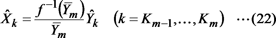
図31に、第五実施形態の符号化方法の前処理により低周波数ほど細かく、高周波数ほど粗く区間分けして信号圧伸したときの周波数スペクトルの具体例を示す。図31の例では、例えば0~2000Hzの周波数帯は5個の区間に分けられ、例えば5000Hz~8000Hzの周波数帯ではすべて1個の区間に含まれており、低周波数ほど細かく、高周波数ほど粗くなるように処理区間が設定されていることがわかる。
FIG. 31 shows a specific example of a frequency spectrum when signal companding is performed by dividing the section more finely as the low frequency and coarser as the high frequency by the preprocessing of the encoding method of the fifth embodiment. In the example of FIG. 31, for example, the frequency band of 0 to 2000 Hz is divided into 5 sections, and for example, the frequency band of 5000 Hz to 8000 Hz is all included in one section, and is finer as the low frequency and coarser as the high frequency. It can be seen that the processing section is set as follows.
<第六実施形態>
フレーム内でスペクトルに起伏がなく、一様に大きな値を示すような信号に対して、細かく区間を区切って準瞬時圧伸を行った場合、フレーム内のスペクトルの値を一様に小さくしてしまい、量子化の性能に悪影響を与える場合がある。第六実施形態では、その対策として、準瞬時圧伸の処理を階層的に用いる。例えば、まずフレーム内の粗い区間で準瞬時圧伸を行い、エネルギーの高い区間については例えば圧伸関数の逆関数を用いて値を高めておく。その後、より細かい区間で準瞬時圧伸を行う。逆変換では、まず細かい区間で準瞬時逆圧伸を行い、その後、粗い区間で準瞬時逆圧伸を行うことで元の周波数スペクトルを求める。 <Sixth embodiment>
When a signal that has no undulations in the spectrum and shows a uniformly large value is subjected to quasi-instantaneous companding by finely dividing the section, the spectrum value in the frame is uniformly reduced. In other words, the quantization performance may be adversely affected. In the sixth embodiment, a quasi-instantaneous companding process is hierarchically used as a countermeasure. For example, quasi-instantaneous companding is first performed in a rough section in the frame, and the value of a section with high energy is increased using, for example, an inverse function of the companding function. Thereafter, quasi-instantaneous companding is performed in a finer section. In the inverse transformation, first, quasi-instantaneous reverse companding is performed in a fine section, and then, the original frequency spectrum is obtained by performing quasi-instantaneous reverse companding in a rough section.
≪符号化装置≫
第六実施形態の符号化装置は、第二実施形態の符号化装置3において、準瞬時圧伸部101の処理を以下のように変更したものである。ただし、第六実施形態の構成を適用できるのは第二実施形態に限定されず、第一実施形態から第五実施形態のすべての実施形態について適用することができる。第六実施形態の準瞬時圧伸部102は、図32に示すように、代表値算出部112および信号圧伸部122を含み、信号圧伸部122の出力が代表値算出部112へ入力されるように構成される。 <Encoder>
The encoding device of the sixth embodiment is obtained by changing the processing of thequasi-instantaneous companding unit 101 in the encoding device 3 of the second embodiment as follows. However, the configuration of the sixth embodiment can be applied to the second embodiment, and can be applied to all the embodiments from the first embodiment to the fifth embodiment. As shown in FIG. 32, the quasi-instantaneous companding unit 102 of the sixth embodiment includes a representative value calculating unit 112 and a signal companding unit 122, and the output of the signal companding unit 122 is input to the representative value calculating unit 112. Configured to be
第六実施形態の符号化装置は、第二実施形態の符号化装置3において、準瞬時圧伸部101の処理を以下のように変更したものである。ただし、第六実施形態の構成を適用できるのは第二実施形態に限定されず、第一実施形態から第五実施形態のすべての実施形態について適用することができる。第六実施形態の準瞬時圧伸部102は、図32に示すように、代表値算出部112および信号圧伸部122を含み、信号圧伸部122の出力が代表値算出部112へ入力されるように構成される。 <Encoder>
The encoding device of the sixth embodiment is obtained by changing the processing of the
[準瞬時圧伸部102]
準瞬時圧伸部102は、フレーム毎に、周波数変換部130が出力した周波数スペクトルXk(k=0, …, N-1)を受け取り、代表値算出部112および信号圧伸部122での処理を所定の回数繰り返し行った後、重み付周波数スペクトルYk(k=0, …, N-1)を周波数逆変換部140へ出力する。 [Quasi-instantaneous companding part 102]
The quasi-instantaneous companding unit 102 receives the frequency spectrum X k (k = 0,..., N−1) output from thefrequency converting unit 130 for each frame, and the representative value calculating unit 112 and the signal companding unit 122 After the process is repeated a predetermined number of times, the weighted frequency spectrum Y k (k = 0,..., N−1) is output to the frequency inverse transform unit 140.
準瞬時圧伸部102は、フレーム毎に、周波数変換部130が出力した周波数スペクトルXk(k=0, …, N-1)を受け取り、代表値算出部112および信号圧伸部122での処理を所定の回数繰り返し行った後、重み付周波数スペクトルYk(k=0, …, N-1)を周波数逆変換部140へ出力する。 [Quasi-instantaneous companding part 102]
The quasi-instantaneous companding unit 102 receives the frequency spectrum X k (k = 0,..., N−1) output from the
[代表値算出部112]
代表値算出部112は、フレーム毎に、処理対象とする周波数スペクトル~Xk(k=0, …, N-1)を受け取り、Mサンプルの区間毎に代表値-Xm(m=1, …, N/M)を算出し、信号圧伸部122へ出力する。代表値算出部112は、1回目の実行時には、準瞬時圧伸部102から入力された周波数スペクトルXk(k=0, …, N-1)を処理対象の周波数スペクトル~Xk(k=0, …, N-1)として受け取り、2回目以降の実行時には、信号圧伸部122が出力した重み付周波数スペクトルYk(k=0, …, N-1)を処理対象の周波数スペクトル~Xk(k=0, …, N-1)として受け取る。 [Representative value calculation unit 112]
Representativevalue calculation unit 112 for each frame, the frequency spectrum ~ X k (k = 0, ..., N-1) to be processed receives the representative value for each section of the M samples - X m (m = 1, ..., N / M) and output to the signal companding unit 122. In the first execution, the representative value calculation unit 112 uses the frequency spectrum X k (k = 0,..., N−1) input from the quasi-instantaneous companding unit 102 as the frequency spectrum to X k (k = 0,..., N-1), and at the second and subsequent executions, the weighted frequency spectrum Y k (k = 0,. Receive as X k (k = 0,…, N-1).
代表値算出部112は、フレーム毎に、処理対象とする周波数スペクトル~Xk(k=0, …, N-1)を受け取り、Mサンプルの区間毎に代表値-Xm(m=1, …, N/M)を算出し、信号圧伸部122へ出力する。代表値算出部112は、1回目の実行時には、準瞬時圧伸部102から入力された周波数スペクトルXk(k=0, …, N-1)を処理対象の周波数スペクトル~Xk(k=0, …, N-1)として受け取り、2回目以降の実行時には、信号圧伸部122が出力した重み付周波数スペクトルYk(k=0, …, N-1)を処理対象の周波数スペクトル~Xk(k=0, …, N-1)として受け取る。 [Representative value calculation unit 112]
Representative
代表値-Xm(m=1,…,M)は、例えば、絶対値平均であれば、
Representative values - X m (m = 1, ..., M) is, for example, if the absolute value average,

として算出する。
Calculate as
代表値算出部112が代表値を求める区間のサンプル数Mは、繰り返しの度に毎回異なるものを用いるように構成してもよい。例えば、1回目にはM=N/2のように処理区間が粗くなるようにし、2回目にはM=N/8のように処理区間が細かくなるようにする。
The sample number M of the section for which the representative value calculation unit 112 obtains the representative value may be configured to be different every time it is repeated. For example, the processing interval is made coarser as M = N / 2 at the first time, and the processing interval is made finer as M = N / 8 at the second time.
[信号圧伸部122]
信号圧伸部122は、フレーム毎に、代表値算出部112が出力した代表値-Xm(m=1, …, N/M)と、処理対象とする周波数スペクトル~Xk(k=0, …, N-1)とを受け取り、以下のように重み付周波数スペクトルYk(k=0, …, N-1)を生成し、周波数逆変換部140へ出力する。信号圧伸部122は、1回目の実行時には、準瞬時圧伸部102から入力された周波数スペクトルXk(k=0, …, N-1)を処理対象の周波数スペクトル~Xk(k=0, …, N-1)として受け取り、2回目以降の実行時には、前回の実行時に出力した重み付周波数スペクトルYk(k=0, …, N-1)を保存しておき、処理対象の周波数スペクトル~Xk(k=0, …, N-1)として利用する。 [Signal companding section 122]
Signal companding unit 122, for each frame, the representative value representative value calculating section 112 has output - X m (m = 1, ..., N / M) and the frequency spectrum to be processed ~ X k (k = 0 ,..., N−1), and generates a weighted frequency spectrum Y k (k = 0,..., N−1) as follows and outputs it to the frequency inverse transform unit 140. In the first execution, the signal companding unit 122 uses the frequency spectrum X k (k = 0,..., N−1) input from the quasi-instantaneous companding unit 102 as the frequency spectrum to X k (k = 0, ..., N-1), and at the second and subsequent executions, the weighted frequency spectrum Y k (k = 0, ..., N-1) output at the previous execution is saved and the processing target Used as frequency spectrum ~ Xk (k = 0, ..., N-1).
信号圧伸部122は、フレーム毎に、代表値算出部112が出力した代表値-Xm(m=1, …, N/M)と、処理対象とする周波数スペクトル~Xk(k=0, …, N-1)とを受け取り、以下のように重み付周波数スペクトルYk(k=0, …, N-1)を生成し、周波数逆変換部140へ出力する。信号圧伸部122は、1回目の実行時には、準瞬時圧伸部102から入力された周波数スペクトルXk(k=0, …, N-1)を処理対象の周波数スペクトル~Xk(k=0, …, N-1)として受け取り、2回目以降の実行時には、前回の実行時に出力した重み付周波数スペクトルYk(k=0, …, N-1)を保存しておき、処理対象の周波数スペクトル~Xk(k=0, …, N-1)として利用する。 [Signal companding section 122]
圧伸関数f(x)による変換後の代表値f(-Xm)および元の代表値-Xmを用い、Mサンプルの区間毎に周波数スペクトルのサンプル値~Xkを、以下のように重み付周波数スペクトルYkに変形する。
Companding function f (x) by the conversion after the representative value f (- X m) and the original representative value - with X m, the sample values ~ X k of the frequency spectrum for each section of the M samples, as follows It is transformed into a weighted frequency spectrum Yk .

信号圧伸部122が用いる圧伸関数f(x)は、繰り返しの度に毎回異なるものを用いるように構成してもよい。例えば、1回目には圧伸関数f(x)の逆関数f-1(x)を用い、2回目には圧伸関数f(x)を用いるようにする。
The companding function f (x) used by the signal companding unit 122 may be configured to use a different one each time it is repeated. For example, the inverse function f −1 (x) of the companding function f (x) is used for the first time, and the companding function f (x) is used for the second time.
≪復号装置≫
第六実施形態の復号装置は、第二実施形態の復号装置4において、準瞬時逆圧伸部251の処理を以下のように変更したものである。ただし、第六実施形態の構成を適用できるのは第二実施形態に限定されず、第一実施形態から第五実施形態のすべての実施形態について適用することができる。第六実施形態の準瞬時逆圧伸部252は、図33に示すように、圧伸代表値算出部262および信号逆圧伸部272を含み、信号逆圧伸部272の出力が圧伸代表値算出部262へ入力されるように構成される。 ≪Decoding device≫
The decoding device of the sixth embodiment is obtained by changing the processing of the quasi-instantaneousreverse companding unit 251 in the decoding device 4 of the second embodiment as follows. However, the configuration of the sixth embodiment can be applied to the second embodiment, and can be applied to all the embodiments from the first embodiment to the fifth embodiment. As shown in FIG. 33, the quasi-instantaneous reverse companding unit 252 of the sixth embodiment includes a companding representative value calculating unit 262 and a signal reverse companding unit 272, and the output of the signal reverse companding unit 272 is a companding representative. It is configured to be input to the value calculation unit 262.
第六実施形態の復号装置は、第二実施形態の復号装置4において、準瞬時逆圧伸部251の処理を以下のように変更したものである。ただし、第六実施形態の構成を適用できるのは第二実施形態に限定されず、第一実施形態から第五実施形態のすべての実施形態について適用することができる。第六実施形態の準瞬時逆圧伸部252は、図33に示すように、圧伸代表値算出部262および信号逆圧伸部272を含み、信号逆圧伸部272の出力が圧伸代表値算出部262へ入力されるように構成される。 ≪Decoding device≫
The decoding device of the sixth embodiment is obtained by changing the processing of the quasi-instantaneous
[準瞬時逆圧伸部252]
準瞬時逆圧伸部252は、フレーム毎に、周波数変換部280が出力した復号重み付周波数スペクトル^Yk(k=0, …, N-1)を受け取り、圧伸代表値算出部262および信号逆圧伸部272での処理を所定の回数繰り返し行い、復号周波数スペクトル^Xk(k=0, …, N-1)を周波数逆変換部290へ出力する。 [Quasi-instantaneous reverse companding section 252]
The quasi-instantaneous companding unit 252 receives the decoding weighted frequency spectrum ^ Y k (k = 0,..., N−1) output from thefrequency converting unit 280 for each frame, and displays the companding representative value calculating unit 262 and The processing in the signal reverse companding unit 272 is repeated a predetermined number of times, and the decoded frequency spectrum ^ X k (k = 0,..., N−1) is output to the frequency inverse converting unit 290.
準瞬時逆圧伸部252は、フレーム毎に、周波数変換部280が出力した復号重み付周波数スペクトル^Yk(k=0, …, N-1)を受け取り、圧伸代表値算出部262および信号逆圧伸部272での処理を所定の回数繰り返し行い、復号周波数スペクトル^Xk(k=0, …, N-1)を周波数逆変換部290へ出力する。 [Quasi-instantaneous reverse companding section 252]
The quasi-instantaneous companding unit 252 receives the decoding weighted frequency spectrum ^ Y k (k = 0,..., N−1) output from the
[圧伸代表値算出部262]
圧伸代表値算出部262は、フレーム毎に、処理対象とする周波数スペクトル~Yk(k=0, …, N-1)を受け取り、復号装置に対応する符号化装置の代表値算出部112と同様にして、Mサンプルの区間毎に代表値-Ym(m=1, …, N/M)を算出し、圧伸代表値-Ymとして信号逆圧伸部272へ出力する。圧伸代表値-Ymの算出方法は復号装置に対応する符号化装置の代表値算出部112と同じものを用いる。圧伸代表値算出部262は、1回目の実行時には、準瞬時逆圧伸部252から入力された復号重み付周波数スペクトル^Yk(k=0, …, N-1)を処理対象の周波数スペクトル~Yk(k=0, …, N-1)として受け取り、2回目以降の実行時には、信号逆圧伸部272が出力した復号周波数スペクトル^Xk(k=0, …, N-1)を処理対象の周波数スペクトル~Yk(k=0, …, N-1)として受け取る。 [Drawing representative value calculation unit 262]
The companding representativevalue calculation unit 262 receives the frequency spectrum ~ Y k (k = 0, ..., N-1) to be processed for each frame, and represents the representative value calculation unit 112 of the encoding device corresponding to the decoding device. in the same manner as the representative value for each section of the M samples - Y m (m = 1, ..., N / M) is calculated, companding representative value - outputs to the signal inverse companding unit 272 as Y m. Companding representative value - calculation method of Y m are used the same as the representative value calculation unit 112 of the coding apparatus corresponding to the decoding apparatus. The companding representative value calculation unit 262 executes the decoding weighted frequency spectrum ^ Y k (k = 0,..., N−1) input from the quasi-instantaneous reverse companding unit 252 at the time of the first execution. Spectrum ~ Y k (k = 0,..., N-1) received at the second and subsequent executions, the decoded frequency spectrum ^ X k (k = 0,..., N-1) output by the signal counter companding unit 272 ) As a frequency spectrum to be processed ~ Yk (k = 0, ..., N-1).
圧伸代表値算出部262は、フレーム毎に、処理対象とする周波数スペクトル~Yk(k=0, …, N-1)を受け取り、復号装置に対応する符号化装置の代表値算出部112と同様にして、Mサンプルの区間毎に代表値-Ym(m=1, …, N/M)を算出し、圧伸代表値-Ymとして信号逆圧伸部272へ出力する。圧伸代表値-Ymの算出方法は復号装置に対応する符号化装置の代表値算出部112と同じものを用いる。圧伸代表値算出部262は、1回目の実行時には、準瞬時逆圧伸部252から入力された復号重み付周波数スペクトル^Yk(k=0, …, N-1)を処理対象の周波数スペクトル~Yk(k=0, …, N-1)として受け取り、2回目以降の実行時には、信号逆圧伸部272が出力した復号周波数スペクトル^Xk(k=0, …, N-1)を処理対象の周波数スペクトル~Yk(k=0, …, N-1)として受け取る。 [Drawing representative value calculation unit 262]
The companding representative
圧伸代表値-Ym(m=1, …, N/M)は、例えば、絶対値平均であれば、
The companding representative value - Y m (m = 1,…, N / M) is, for example, the average of absolute values,

として算出する。
Calculate as
圧伸代表値算出部262が圧伸代表値を求める区間のサンプル数Mは、繰り返しの度に復号装置に対応する符号化装置の代表値算出部112が用いたサンプル数Mに対応するものを用いるように構成する。例えば、1回目にはM=N/8のように処理区間が細かくなるようにし、2回目にはM=N/2のように処理区間が粗くなるようにする。
The number of samples M in the section for which the companding representative value calculation unit 262 obtains the companding representative value corresponds to the number of samples M used by the representative value calculating unit 112 of the encoding device corresponding to the decoding device each time it is repeated. Configure to use. For example, the processing interval is narrowed such that M = N / 8 for the first time, and the processing interval is rough such that M = N / 2 for the second time.
[信号逆圧伸部272]
信号逆圧伸部272は、フレーム毎に、圧伸代表値算出部262が出力した圧伸代表値-Ym(m=1, …, N/M)と、処理対象とする周波数スペクトル~Yk(k=0, …, N-1)とを受け取り、以下のように復号周波数スペクトル^Xk(k=0, …, N-1)を生成し、周波数逆変換部290へ出力する。信号逆圧伸部272は、1回目の実行時には、準瞬時逆圧伸部252から入力された復号重み付周波数スペクトル^Yk(k=0, …, N-1)を処理対象の周波数スペクトル~Yk(k=0, …, N-1)として受け取り、2回目以降の実行時には、前回の実行時に出力した復号周波数スペクトル^Xk(k=0, …, N-1)を保存しておき、処理対象の周波数スペクトル~Yk(k=0, …, N-1)として利用する。 [Signal reverse companding section 272]
Signalinverse companding unit 272, for each frame, companding typical companding representative value calculating section 262 outputs - Y m (m = 1, ..., N / M) and the frequency spectrum to be processed ~ Y k (k = 0,..., N−1) is received, a decoded frequency spectrum ^ X k (k = 0,..., N−1) is generated as follows, and output to the frequency inverse transform unit 290. In the first execution, the signal reverse companding unit 272 uses the decoding weighted frequency spectrum ^ Y k (k = 0,..., N−1) input from the quasi-instantaneous companding unit 252 as a processing target frequency spectrum. ~ Y k (k = 0,…, N-1) is received as the second and subsequent executions, and the decoded frequency spectrum ^ X k (k = 0,…, N-1) output during the previous execution is saved. The frequency spectrum to be processed is used as Y k (k = 0,..., N−1).
信号逆圧伸部272は、フレーム毎に、圧伸代表値算出部262が出力した圧伸代表値-Ym(m=1, …, N/M)と、処理対象とする周波数スペクトル~Yk(k=0, …, N-1)とを受け取り、以下のように復号周波数スペクトル^Xk(k=0, …, N-1)を生成し、周波数逆変換部290へ出力する。信号逆圧伸部272は、1回目の実行時には、準瞬時逆圧伸部252から入力された復号重み付周波数スペクトル^Yk(k=0, …, N-1)を処理対象の周波数スペクトル~Yk(k=0, …, N-1)として受け取り、2回目以降の実行時には、前回の実行時に出力した復号周波数スペクトル^Xk(k=0, …, N-1)を保存しておき、処理対象の周波数スペクトル~Yk(k=0, …, N-1)として利用する。 [Signal reverse companding section 272]
Signal
圧伸関数f(x)の逆関数f-1(y)により変換した圧伸代表値f-1(-Ym)および元の圧伸代表値-Ymを用い、所定のMサンプルの区間毎に復号重み付周波数スペクトルのサンプル値^Ykを、以下のように復号周波数スペクトル^Xkのサンプル値に変形する。
Companding function f companding representative value was converted by the inverse function f -1 (y) of (x) f -1 (- Y m) and the original companding representative values - with Y m, predetermined M samples of the section Every time, the sample value ^ Y k of the decoding weighted frequency spectrum is transformed into the sample value of the decoding frequency spectrum ^ X k as follows.

信号逆圧伸部272が用いる圧伸関数f(x)の逆関数f-1(y)は、繰り返しの度に信号圧伸部122が用いた圧伸関数f(x)に対応する逆関数を用いるように構成する。例えば、1回目には圧伸関数f(x)の逆関数f-1(x)に対する逆関数として圧伸関数f(x)を用い、2回目には圧伸関数f(x) に対する逆関数として圧伸関数f(x)の逆関数f-1(x)を用いるようにする。
The inverse function f −1 (y) of the companding function f (x) used by the signal inverse companding unit 272 is an inverse function corresponding to the companding function f (x) used by the signal companding unit 122 every time it is repeated. It is configured to use. For example, the companding function f (x) is used as the inverse function of the inverse function f −1 (x) of the companding function f (x) at the first time, and the inverse function with respect to the companding function f (x) is performed the second time. The inverse function f −1 (x) of the companding function f (x) is used as
図34に、第六実施形態の符号化方法の前処理により、代表値算出と信号圧伸の処理を複数回繰り返したときの周波数スペクトルの具体例を示す。図34の例では、繰り返しのたびに各区間に含まれるサンプル数Mを異なるように構成している。具体的には、1回目の処理では1フレームが2個の区間に分かれるようにM=N/2に設定し、2回目の処理では1フレームが8個の区間に分かれるようにM=N/8に設定している。
FIG. 34 shows a specific example of a frequency spectrum when the representative value calculation and the signal companding process are repeated a plurality of times by the preprocessing of the encoding method of the sixth embodiment. In the example of FIG. 34, the number of samples M included in each section is different for each repetition. Specifically, M = N / 2 is set so that one frame is divided into two sections in the first process, and M = N / so that one frame is divided into eight sections in the second process. 8 is set.
<第七実施形態>
上述の各実施形態で説明した符号化装置1、7が備える準瞬時圧伸部100、符号化装置3、5が備える準瞬時圧伸部101、復号装置2、8が備える準瞬時逆圧伸部250、および復号装置4、6が備える準瞬時逆圧伸部251は、独立したサンプル列変形装置として構成することも可能である。 <Seventh embodiment>
Thequasi-instantaneous companding unit 100 included in the encoding devices 1 and 7 described in the above embodiments, the quasi-instantaneous companding unit 101 included in the encoding devices 3 and 5, and the quasi-instantaneous reverse companding included in the decoding devices 2 and 8. The quasi-instantaneous reverse companding unit 251 included in the unit 250 and the decoding devices 4 and 6 can also be configured as an independent sample train deforming device.
上述の各実施形態で説明した符号化装置1、7が備える準瞬時圧伸部100、符号化装置3、5が備える準瞬時圧伸部101、復号装置2、8が備える準瞬時逆圧伸部250、および復号装置4、6が備える準瞬時逆圧伸部251は、独立したサンプル列変形装置として構成することも可能である。 <Seventh embodiment>
The
準瞬時圧伸部101を独立したサンプル列変形装置とする場合、以下のように構成する。このサンプル列変形装置33は、入力音響信号に対応する周波数領域信号を変形して得た重み付周波数領域信号を符号化する符号化装置に入力するための重み付周波数領域信号、または、入力音響信号に対応する周波数領域信号を変形して得た重み付周波数領域信号に対応する重み付時間領域信号を符号化する符号化装置に入力するための重み付時間領域信号に対応する重み付周波数領域信号、を得るサンプル列変形装置であって、例えば、図35に示すように、代表値算出部111と信号圧伸部121とを含む。代表値算出部111は、所定時間区間ごとに、入力音響信号に対応する周波数領域信号のサンプル列から、当該周波数領域サンプル列の周波数サンプル数より少ない複数サンプルによる周波数区間ごとに、当該周波数区間に含まれるサンプルのサンプル値から当該周波数区間の代表値を算出する。信号圧伸部121は、所定時間区間ごとに、逆関数を定義できる圧伸関数による代表値の関数値に応じた重みと、周波数領域サンプル列中の当該代表値に対応する各サンプルと、を乗算した周波数領域サンプル列を、重み付周波数領域信号のサンプル列として得る。
When the quasi-instantaneous companding unit 101 is an independent sample train deforming device, it is configured as follows. This sample sequence transformation device 33 is a weighted frequency domain signal for input to an encoding device for encoding a weighted frequency domain signal obtained by transforming a frequency domain signal corresponding to an input acoustic signal, or an input acoustic signal. A weighted frequency domain corresponding to a weighted time domain signal for input to an encoding device for encoding a weighted time domain signal corresponding to a weighted frequency domain signal obtained by modifying a frequency domain signal corresponding to the signal For example, as shown in FIG. 35, the sample train deforming apparatus for obtaining a signal includes a representative value calculating unit 111 and a signal companding unit 121. The representative value calculation unit 111 calculates, for each predetermined time interval, from the sample sequence of the frequency domain signal corresponding to the input acoustic signal, for each frequency interval with a plurality of samples less than the number of frequency samples in the frequency domain sample sequence, The representative value of the frequency section is calculated from the sample values of the included samples. The signal companding unit 121 includes, for each predetermined time interval, a weight corresponding to the function value of the representative value by the companding function that can define an inverse function, and each sample corresponding to the representative value in the frequency domain sample sequence. The multiplied frequency domain sample sequence is obtained as a sample sequence of the weighted frequency domain signal.
準瞬時逆圧伸部251を独立したサンプル列変形装置とする場合、以下のように構成する。このサンプル列変形装置34は、復号音響信号に対応する周波数領域信号に対応する重み付周波数領域信号を復号により得る復号装置が得た重み付周波数領域信号、または、復号音響信号に対応する周波数領域信号に対応する重み付時間領域信号を復号により得る復号装置が得た重み付時間領域信号に対応する重み付周波数領域信号、から復号音響信号に対応する周波数領域信号を得るサンプル列変形装置であって、例えば、図36に示すように、圧伸代表値算出部261と信号逆圧伸部271とを含む。圧伸代表値算出部261は、所定時間区間ごとに、重み付周波数領域信号のサンプル列から、当該重み付周波数領域信号のサンプル列の周波数サンプル数より少ない複数サンプルによる周波数区間ごとに当該周波数区間に含まれるサンプルのサンプル値から当該周波数区間の代表値を算出する。信号逆圧伸部271は、所定時間区間ごとに、逆関数を定義できる圧伸関数による代表値の関数値に応じた重みと、重み付周波数領域信号のサンプル列中の当該代表値に対応する各サンプルと、を乗算した周波数領域サンプル列を、復号音響信号に対応する周波数領域信号のサンプル列として得る。
When the quasi-instantaneous reverse companding section 251 is an independent sample train deforming device, it is configured as follows. This sample sequence transformation device 34 is a weighted frequency domain signal obtained by a decoding device that obtains a weighted frequency domain signal corresponding to a frequency domain signal corresponding to a decoded acoustic signal, or a frequency domain corresponding to a decoded acoustic signal. A sample sequence transformation device that obtains a frequency domain signal corresponding to a decoded acoustic signal from a weighted frequency domain signal corresponding to a weighted time domain signal obtained by a decoding device that obtains a weighted time domain signal corresponding to the signal by decoding. For example, as shown in FIG. 36, a companding representative value calculation unit 261 and a signal reverse companding unit 271 are included. The companding representative value calculation unit 261 performs, for each predetermined time interval, from the sample sequence of the weighted frequency domain signal, the frequency segment for each frequency segment by a plurality of samples smaller than the number of frequency samples in the sample sequence of the weighted frequency domain signal. The representative value of the frequency section is calculated from the sample values of the samples included in. The signal reverse companding unit 271 corresponds to a weight corresponding to a function value of a representative value by a companding function capable of defining an inverse function for each predetermined time interval, and the representative value in the sample sequence of the weighted frequency domain signal. A frequency domain sample sequence obtained by multiplying each sample is obtained as a sample sequence of the frequency domain signal corresponding to the decoded acoustic signal.
準瞬時圧伸部100を独立したサンプル列変形装置とする場合、以下のように構成する。このサンプル列変形装置31は、入力音響信号を変形して得た重み付音響信号を符号化する符号化装置に入力するための重み付音響信号、または、入力音響信号を変形して得た重み付音響信号に対応する重み付周波数領域信号を符号化する符号化装置に入力するための重み付周波数領域信号に対応する重み付音響信号、を得るサンプル列変形装置であって、例えば、図35に示すように、代表値算出部110と信号圧伸部120とを含む。代表値算出部110は、所定時間区間ごとに、時間領域の入力音響信号のサンプル列から、当該入力音響信号のサンプル列のサンプル数より少ない複数サンプルによる時間区間ごとに、当該時間区間に含まれるサンプルのサンプル値から当該時間区間の代表値を算出する。信号圧伸部120は、所定時間区間ごとに、逆関数を定義できる圧伸関数による代表値の関数値に応じた重みと、入力音響信号のサンプル列中の当該代表値に対応する各サンプルと、を乗算した時間領域サンプル列を、重み付音響信号のサンプル列として得る。
When the quasi-instantaneous companding unit 100 is an independent sample train deforming device, it is configured as follows. This sample string transformation device 31 is a weighted acoustic signal for input to an encoding device that encodes a weighted acoustic signal obtained by transforming an input acoustic signal, or a weight obtained by transforming an input acoustic signal. A sample-sequence modification device that obtains a weighted acoustic signal corresponding to a weighted frequency domain signal for input to an encoding device that encodes a weighted frequency domain signal corresponding to the attached acoustic signal, for example, FIG. As shown, the representative value calculation unit 110 and the signal companding unit 120 are included. The representative value calculation unit 110 is included in the time interval for each predetermined time interval from a sample sequence of the input acoustic signal in the time domain to a time interval of a plurality of samples smaller than the number of samples in the sample sequence of the input acoustic signal. A representative value of the time interval is calculated from the sample value of the sample. The signal companding unit 120 has a weight corresponding to a function value of a representative value by a companding function capable of defining an inverse function for each predetermined time interval, each sample corresponding to the representative value in the sample sequence of the input acoustic signal, and , And a time-domain sample sequence obtained by multiplying and is obtained as a sample sequence of the weighted acoustic signal.
準瞬時逆圧伸部250を独立したサンプル列変形装置とする場合、以下のように構成する。このサンプル列変形装置32は、復号音響信号に対応する時間領域の重み付音響信号を復号により得る復号装置が得た時間領域の重み付音響信号、または、復号音響信号に対応する周波数領域の重み付音響信号を復号により得る復号装置が得た周波数領域の重み付音響信号に対応する時間領域の重み付音響信号、から復号音響信号を得るサンプル列変形装置であって、例えば、図36に示すように、圧伸代表値算出部260と信号逆圧伸部270とを含む。圧伸代表値算出部260は、所定時間区間ごとに、時間領域の重み付音響信号のサンプル列から、当該重み付音響信号のサンプル列のサンプル数より少ない複数サンプルによる時間区間ごとに、当該時間区間に含まれるサンプルのサンプル値から当該時間区間の代表値を算出する。信号逆圧伸部270は、所定時間区間ごとに、逆関数を定義できる圧伸関数による代表値の関数値に応じた重みと、重み付周波数領域信号のサンプル列中の当該代表値に対応する各サンプルと、を乗算した周波数領域サンプル列を、復号音響信号に対応する周波数領域信号のサンプル列として得る。
When the quasi-instantaneous reverse companding section 250 is an independent sample train deforming device, it is configured as follows. This sample sequence transformation device 32 obtains a time-domain weighted acoustic signal corresponding to the decoded acoustic signal by decoding. The time-domain weighted acoustic signal obtained by the decoding device or a frequency-domain weight corresponding to the decoded acoustic signal. FIG. 36 shows a sample train deforming device that obtains a decoded acoustic signal from a weighted acoustic signal in a time domain corresponding to a weighted acoustic signal in a frequency domain obtained by a decoding device that obtains an attached acoustic signal by decoding. As described above, a companding representative value calculation unit 260 and a signal reverse companding unit 270 are included. The companding representative value calculation unit 260 performs, for each predetermined time interval, from the sample sequence of the weighted acoustic signal in the time domain, for each time interval by a plurality of samples less than the number of samples in the sample sequence of the weighted acoustic signal. A representative value of the time interval is calculated from the sample values of the samples included in the interval. The signal reverse companding unit 270 corresponds to the weight corresponding to the function value of the representative value by the companding function capable of defining the inverse function for each predetermined time interval, and the representative value in the sample sequence of the weighted frequency domain signal. A frequency domain sample sequence obtained by multiplying each sample is obtained as a sample sequence of the frequency domain signal corresponding to the decoded acoustic signal.
サンプル列変形装置33、34は、複数サンプルによる区間が、低周波数に対応する区間であるほど含まれるサンプル数が少なく、高周波数に対応する区間であるほど含まれるサンプル数が多くなるように設定されたサンプル列変形装置35として構成することができる。
The sample string transformation devices 33 and 34 are set so that the number of samples included in the section corresponding to the low frequency is small as the section of the plurality of samples is in the section corresponding to the low frequency, and the number of samples included in the section corresponding to the high frequency is increased. The sample row deforming device 35 can be configured.
サンプル列変形装置31~35は、入力音響信号の複数サンプルによる区間ごとに代表値を算出することと、算出した代表値の関数値に応じた重みとサンプル列の各サンプルとを乗算することを、所定の回数繰り返し実行するサンプル列変形装置36として構成することができる。
The sample string deforming devices 31 to 35 calculate a representative value for each section of a plurality of samples of the input acoustic signal, and multiply each sample of the sample string by a weight corresponding to the calculated function value of the representative value. The sample train deforming device 36 can be configured to be repeatedly executed a predetermined number of times.
<第八実施形態>
フレーム毎の符号長の上限が一定であると、入力される信号のフレーム毎の統計的性質等に依存して圧縮効率が変動し、量子化幅が小さくできるフレームや、大きな量子化幅を用いざるを得ないフレームが現れる。中でも圧縮効率が高く、量子化幅が小さくできるようなフレームにおいては、前処理及び後処理を行わずとも量子化誤差が聴覚的に十分に小さいことが多い。準瞬時圧伸による前処理及び準瞬時逆圧伸による後処理は、復号信号の波形の二乗誤差のような数値的誤差を大きくする代わりに聴覚的な歪を低減するような性質をもっている。従って、入力音響信号や入力音響信号に対応する周波数領域信号の量子化幅の小さいフレームについては、信号の前処理及び後処理を用いて聴覚的な歪を低減しようとするよりも、前処理及び後処理を用いず単純な復号信号の波形の数値的誤差を下げることを目指したほうが、復号信号を再び圧縮したり加工したりする際には都合がよい。 <Eighth embodiment>
If the upper limit of the code length for each frame is constant, the compression efficiency varies depending on the statistical properties of the input signal for each frame, and a frame with a small quantization width or a large quantization width is used. An inevitable frame appears. In particular, in a frame where the compression efficiency is high and the quantization width can be reduced, the quantization error is often sufficiently small auditorily without performing pre-processing and post-processing. The pre-processing by quasi-instantaneous companding and the post-processing by quasi-instantaneous inverse companding have the property of reducing auditory distortion instead of increasing numerical errors such as the square error of the waveform of the decoded signal. Therefore, for a frame with a small quantization width of the input acoustic signal and the frequency domain signal corresponding to the input acoustic signal, the pre-processing and the post-processing are used instead of the pre-processing and the post-processing. It is more convenient to compress or process the decoded signal again, aiming to reduce the numerical error of the waveform of the simple decoded signal without using post-processing.
そこで、第八実施形態では、準瞬時圧伸及び準瞬時逆圧伸による信号の前処理及び後処理を行うか否かを、入力音響信号や入力音響信号に対応する周波数領域信号の量子化幅の値に基づいてフレーム毎に選択する。
Therefore, in the eighth embodiment, whether or not to perform pre-processing and post-processing of the signal by quasi-instantaneous companding and quasi-instantaneous reverse companding depends on the quantization width of the frequency domain signal corresponding to the input acoustic signal or the input acoustic signal. Select for each frame based on the value of.
なお、第八実施形態は、第一実施形態、第二実施形態、第五実施形態、これらの実施形態に適用した第六実施形態、に適用することができる。
The eighth embodiment can be applied to the first embodiment, the second embodiment, the fifth embodiment, and the sixth embodiment applied to these embodiments.
第八実施形態の符号化装置および復号装置によれば、符号化装置においては入力音響信号や入力音響信号に対応する周波数領域信号の量子化幅の値に基づき信号の前処理の有無を選択し、復号装置においては復号により得た量子化幅に基づき後処理の有無を選択することにより、符号化装置で前処理のなされたフレームのみに対して、符号化装置が行った前処理に対応する後処理を施すことができる。すなわち、符号化装置が行った符号化処理に対応する復号処理を復号装置が行うことが可能となる。
According to the encoding device and the decoding device of the eighth embodiment, in the encoding device, the presence or absence of signal preprocessing is selected based on the value of the quantization width of the input acoustic signal or the frequency domain signal corresponding to the input acoustic signal. In the decoding device, by selecting the presence or absence of post-processing based on the quantization width obtained by decoding, only the frame pre-processed by the encoding device corresponds to the pre-processing performed by the encoding device. Post-processing can be performed. That is, the decoding apparatus can perform a decoding process corresponding to the encoding process performed by the encoding apparatus.
≪符号化装置41≫
第八実施形態の符号化装置の一例として、第一実施形態の符号化装置1を変更したものについて説明する。第八実施形態の符号化装置41は、図37に示すように、信号前処理部51、量子化部52、可逆符号化部18、および多重化部19を含む。第八実施形態の符号化装置41は、量子化部52が行う処理が複雑であるため、図39を参照して、第八実施形態の符号化装置41が実行する符号化方法の処理手続きを説明する。 << Encoder 41 >>
As an example of the encoding apparatus according to the eighth embodiment, a modification of theencoding apparatus 1 according to the first embodiment will be described. As illustrated in FIG. 37, the encoding device 41 according to the eighth embodiment includes a signal preprocessing unit 51, a quantization unit 52, a lossless encoding unit 18, and a multiplexing unit 19. Since the process performed by the quantization unit 52 is complicated in the encoding device 41 of the eighth embodiment, the processing procedure of the encoding method executed by the encoding apparatus 41 of the eighth embodiment is described with reference to FIG. explain.
第八実施形態の符号化装置の一例として、第一実施形態の符号化装置1を変更したものについて説明する。第八実施形態の符号化装置41は、図37に示すように、信号前処理部51、量子化部52、可逆符号化部18、および多重化部19を含む。第八実施形態の符号化装置41は、量子化部52が行う処理が複雑であるため、図39を参照して、第八実施形態の符号化装置41が実行する符号化方法の処理手続きを説明する。 << Encoder 41 >>
As an example of the encoding apparatus according to the eighth embodiment, a modification of the
ステップS11において、音声や音楽などの時間領域の音響信号Xk(k=0, …, N-1)がフレーム単位で符号化装置41へ入力される。符号化装置41へ入力された音響信号Xkは、まず、量子化部52へ入力される。
In step S11, a time domain acoustic signal X k (k = 0,..., N−1) such as voice or music is input to the encoding device 41 in units of frames. The acoustic signal X k input to the encoding device 41 is first input to the quantization unit 52.
[量子化部52:ステップS51とS52]
ステップS51において、量子化部52は、フレーム毎の音響信号Xk(k=0, …, N-1)を受け取り、目標の符号長に適うように音響信号Xkをスカラー量子化し、量子化信号を得る。ステップS51においては、量子化部52は、例えば、従来技術と同様に、音響信号Xkを量子化幅に対応する値で除算して整数値を量子化信号として得る。量子化幅は、例えば、可逆符号化部18による圧縮結果の符号長を基にして、符号長が目標の符号長に対して長過ぎる場合には量子化幅を大きくし、符号長が目標の符号長に対して短過ぎる場合には量子化幅を小さくするというように探索する。すなわち、量子化幅は、探索により得た値であり、最適であると推測される値である。 [Quantization unit 52: Steps S51 and S52]
In step S51, thequantization unit 52 receives the acoustic signal X k (k = 0,..., N−1) for each frame, scalar quantizes the acoustic signal X k so as to meet the target code length, and quantizes it. Get a signal. In step S51, the quantizing unit 52, for example, as in the prior art, to obtain an integer value as a quantized signal by dividing a sound signal X k with a value corresponding to the quantization width. For example, based on the code length of the compression result by the lossless encoding unit 18, the quantization width is increased when the code length is too long for the target code length, and the code length is set to the target code length. If the code length is too short, the search is performed such that the quantization width is reduced. That is, the quantization width is a value obtained by searching and is a value estimated to be optimal.
ステップS51において、量子化部52は、フレーム毎の音響信号Xk(k=0, …, N-1)を受け取り、目標の符号長に適うように音響信号Xkをスカラー量子化し、量子化信号を得る。ステップS51においては、量子化部52は、例えば、従来技術と同様に、音響信号Xkを量子化幅に対応する値で除算して整数値を量子化信号として得る。量子化幅は、例えば、可逆符号化部18による圧縮結果の符号長を基にして、符号長が目標の符号長に対して長過ぎる場合には量子化幅を大きくし、符号長が目標の符号長に対して短過ぎる場合には量子化幅を小さくするというように探索する。すなわち、量子化幅は、探索により得た値であり、最適であると推測される値である。 [Quantization unit 52: Steps S51 and S52]
In step S51, the
ステップS52において、量子化部52は、ステップS51で量子化に使用した量子化幅が所定の閾値よりも小さかった、または所定の閾値以下であったフレームについては、量子化信号を可逆符号化部18へ、量子化に使用した量子化幅を多重化部19へ、それぞれ出力し、それ以外のフレームについては、当該フレームの信号前処理部を動作させるための情報を信号前処理部51へ出力する。
In step S52, the quantization unit 52 converts the quantized signal into a lossless encoding unit for a frame in which the quantization width used in the quantization in step S51 is smaller than a predetermined threshold value or less than the predetermined threshold value. 18, the quantization width used for quantization is output to the multiplexing unit 19, and for the other frames, information for operating the signal preprocessing unit of the frame is output to the signal preprocessing unit 51. To do.
[信号前処理部51]
信号前処理部51は、量子化部52から当該フレームの信号前処理部を動作させるための情報が入力された場合、すなわち、当該フレームの音響信号の量子化幅が所定の閾値以上であるか所定の閾値を超えている場合に限り、符号化装置41へ入力された音響信号Xkを受け取り、第一実施形態の信号前処理部11と同様の処理を行い、フレーム毎の重み付信号Yk(k=0, …, N-1)を量子化部52へ出力する。(ステップS12、S13) [Signal preprocessing unit 51]
Thesignal preprocessing unit 51 receives information for operating the signal preprocessing unit of the frame from the quantization unit 52, that is, whether the quantization width of the acoustic signal of the frame is equal to or larger than a predetermined threshold value. Only when the predetermined threshold value is exceeded, the acoustic signal X k input to the encoding device 41 is received, the same processing as the signal preprocessing unit 11 of the first embodiment is performed, and the weighted signal Y for each frame k (k = 0,..., N−1) is output to the quantization unit 52. (Steps S12 and S13)
信号前処理部51は、量子化部52から当該フレームの信号前処理部を動作させるための情報が入力された場合、すなわち、当該フレームの音響信号の量子化幅が所定の閾値以上であるか所定の閾値を超えている場合に限り、符号化装置41へ入力された音響信号Xkを受け取り、第一実施形態の信号前処理部11と同様の処理を行い、フレーム毎の重み付信号Yk(k=0, …, N-1)を量子化部52へ出力する。(ステップS12、S13) [Signal preprocessing unit 51]
The
[量子化部52:ステップS14]
ステップS14において、量子化部52は、信号前処理部51が重み付信号Yk(k=0, …, N-1)を出力したフレーム、すなわち、当該フレームの音響信号の量子化幅が所定の閾値以上であるか所定の閾値を超えているフレームについて、信号前処理部51が出力した当該フレームの重み付信号Yk(k=0, …, N-1)を受け取り、目標の符号長に適うように重み付信号Ykをスカラー量子化し、量子化信号を出力する。ステップS14においては、量子化部52は、例えば、従来技術と同様に、重み付信号Ykを量子化幅に対応する値で除算して整数値を量子化信号として得る。量子化幅は、例えば、可逆符号化部18による圧縮結果の符号長を基にして、符号長が目標の符号長に対して長過ぎる場合には量子化幅を大きくし、符号長が目標の符号長に対して短過ぎる場合には量子化幅を小さくするというように探索する。すなわち、量子化幅は、探索により得た値であり、最適であると推測される値である。 [Quantization unit 52: Step S14]
In step S14, the quantizingunit 52 has a predetermined quantization width of the frame in which the signal preprocessing unit 51 outputs the weighted signal Y k (k = 0,..., N−1), that is, the acoustic signal of the frame. For a frame that is equal to or greater than the threshold value or exceeds the predetermined threshold value, the weighted signal Y k (k = 0,..., N−1) of the frame output from the signal preprocessing unit 51 is received, and the target code length The weighted signal Y k is scalar quantized so as to meet the above, and a quantized signal is output. In step S14, for example, the quantization unit 52 divides the weighted signal Yk by a value corresponding to the quantization width to obtain an integer value as a quantized signal, as in the prior art. For example, based on the code length of the compression result by the lossless encoding unit 18, the quantization width is increased when the code length is too long for the target code length, and the code length is set to the target code length. If the code length is too short, the search is performed such that the quantization width is reduced. That is, the quantization width is a value obtained by searching and is a value estimated to be optimal.
ステップS14において、量子化部52は、信号前処理部51が重み付信号Yk(k=0, …, N-1)を出力したフレーム、すなわち、当該フレームの音響信号の量子化幅が所定の閾値以上であるか所定の閾値を超えているフレームについて、信号前処理部51が出力した当該フレームの重み付信号Yk(k=0, …, N-1)を受け取り、目標の符号長に適うように重み付信号Ykをスカラー量子化し、量子化信号を出力する。ステップS14においては、量子化部52は、例えば、従来技術と同様に、重み付信号Ykを量子化幅に対応する値で除算して整数値を量子化信号として得る。量子化幅は、例えば、可逆符号化部18による圧縮結果の符号長を基にして、符号長が目標の符号長に対して長過ぎる場合には量子化幅を大きくし、符号長が目標の符号長に対して短過ぎる場合には量子化幅を小さくするというように探索する。すなわち、量子化幅は、探索により得た値であり、最適であると推測される値である。 [Quantization unit 52: Step S14]
In step S14, the quantizing
ステップS14の探索により求まる量子化幅は、ほとんどの場合は、ステップS51の探索により求まる量子化幅より大きな値となり、ステップS52における閾値よりも大きな値となる。なお、ステップS14の探索により求まる量子化幅が、ステップS52における閾値よりも小さな値または閾値以下の値とならないようにするためには、ステップS14の探索により求める量子化幅の下限値をステップS52における閾値以上の値または閾値より大きな値とすればよい。
In most cases, the quantization width obtained by the search in step S14 is larger than the quantization width obtained by the search in step S51, and is larger than the threshold value in step S52. In order to prevent the quantization width obtained by the search in step S14 from being a value smaller than or less than the threshold value in step S52, the lower limit value of the quantization width obtained by the search in step S14 is set in step S52. What is necessary is just to set it as the value more than the threshold value in or larger than a threshold value.
量子化部52は、量子化信号を可逆符号化部18へ、量子化に使用した量子化幅を多重化部19へ、それぞれ出力する。
The quantization unit 52 outputs the quantized signal to the lossless encoding unit 18 and the quantization width used for the quantization to the multiplexing unit 19.
[可逆符号化部18、多重化部19]
可逆符号化部18が行うステップS15、多重化部19が行うステップS16は第一実施形態と同様である。 [Reversible encoding unit 18, multiplexing unit 19]
Step S15 performed by thelossless encoding unit 18 and step S16 performed by the multiplexing unit 19 are the same as those in the first embodiment.
可逆符号化部18が行うステップS15、多重化部19が行うステップS16は第一実施形態と同様である。 [
Step S15 performed by the
≪復号装置42≫
第八実施形態の復号装置の一例として、第一実施形態の復号装置2を変更したものについて説明する。第八実施形態の復号装置42は、図38に示すように、多重分離部61、可逆復号部22、逆量子化部23、判定部62、および信号後処理部63を含む。以下では、図40を参照して、第八実施形態の復号装置42が実行する復号方法の処理手続きを説明する。 << Decoding device 42 >>
As an example of the decoding device according to the eighth embodiment, a modification of thedecoding device 2 according to the first embodiment will be described. As illustrated in FIG. 38, the decoding device 42 according to the eighth embodiment includes a demultiplexing unit 61, a lossless decoding unit 22, an inverse quantization unit 23, a determination unit 62, and a signal post-processing unit 63. Hereinafter, with reference to FIG. 40, a processing procedure of the decoding method executed by the decoding device 42 of the eighth embodiment will be described.
第八実施形態の復号装置の一例として、第一実施形態の復号装置2を変更したものについて説明する。第八実施形態の復号装置42は、図38に示すように、多重分離部61、可逆復号部22、逆量子化部23、判定部62、および信号後処理部63を含む。以下では、図40を参照して、第八実施形態の復号装置42が実行する復号方法の処理手続きを説明する。 << Decoding device 42 >>
As an example of the decoding device according to the eighth embodiment, a modification of the
[多重分離部61]
ステップS21において、多重分離部61は、復号装置42へ入力された符号を受け取り、信号符号を可逆復号部22へ、量子化幅符号に対応する量子化幅を逆量子化部23及び判定部62へ、それぞれ出力する。量子化幅を復号により得る処理は多重分離部21と同様である。 [Demultiplexer 61]
In step S <b> 21, thedemultiplexing unit 61 receives the code input to the decoding device 42, converts the signal code to the lossless decoding unit 22, and sets the quantization width corresponding to the quantization width code to the inverse quantization unit 23 and the determination unit 62. Respectively. The process of obtaining the quantization width by decoding is the same as that of the demultiplexing unit 21.
ステップS21において、多重分離部61は、復号装置42へ入力された符号を受け取り、信号符号を可逆復号部22へ、量子化幅符号に対応する量子化幅を逆量子化部23及び判定部62へ、それぞれ出力する。量子化幅を復号により得る処理は多重分離部21と同様である。 [Demultiplexer 61]
In step S <b> 21, the
[可逆復号部22、逆量子化部23]
可逆復号部22が行うステップS22及び逆量子化部23が行うステップS23は第一実施形態と同様である。 [Reversible decoding unit 22 and inverse quantization unit 23]
Step S22 performed by thelossless decoding unit 22 and step S23 performed by the inverse quantization unit 23 are the same as in the first embodiment.
可逆復号部22が行うステップS22及び逆量子化部23が行うステップS23は第一実施形態と同様である。 [
Step S22 performed by the
[判定部62]
ステップS61において、判定部62は、フレーム毎に、逆量子化部23が出力した復号重み付信号^Yk(k=0, …, N-1)及び多重分離部61が出力した量子化幅を受け取り、量子化幅が所定の閾値より小さいまたは所定の閾値以下であるフレームについては、逆量子化部23が出力した復号重み付信号^Yk(k=0, …, N-1)をそのまま出力信号^Xk(k=0, …, N-1)として出力し、それ以外のフレームについては、当該フレームの信号後処理部を動作させるための情報と逆量子化部23が出力した復号重み付信号^Yk(k=0, …, N-1)を信号後処理部63へ出力する。 [Determining unit 62]
In step S61, thedetermination unit 62 determines, for each frame, the decoded weighted signal ^ Y k (k = 0,..., N−1) output from the inverse quantization unit 23 and the quantization width output from the demultiplexing unit 61. And a decoding weighted signal ^ Y k (k = 0,..., N−1) output by the inverse quantization unit 23 is used for a frame whose quantization width is smaller than a predetermined threshold or less than a predetermined threshold. The output signal ^ X k (k = 0,..., N-1) is output as it is, and for the other frames, the information for operating the signal post-processing unit of the frame and the inverse quantization unit 23 output it. The decoding weighted signal ^ Y k (k = 0,..., N−1) is output to the signal post-processing unit 63.
ステップS61において、判定部62は、フレーム毎に、逆量子化部23が出力した復号重み付信号^Yk(k=0, …, N-1)及び多重分離部61が出力した量子化幅を受け取り、量子化幅が所定の閾値より小さいまたは所定の閾値以下であるフレームについては、逆量子化部23が出力した復号重み付信号^Yk(k=0, …, N-1)をそのまま出力信号^Xk(k=0, …, N-1)として出力し、それ以外のフレームについては、当該フレームの信号後処理部を動作させるための情報と逆量子化部23が出力した復号重み付信号^Yk(k=0, …, N-1)を信号後処理部63へ出力する。 [Determining unit 62]
In step S61, the
[信号後処理部63]
信号後処理部63は、判定部62から当該フレームの信号後処理部を動作させるための情報が入力された場合、すなわち、量子化幅が所定の閾値を超えているまたは所定の閾値以上であるフレームについて、逆量子化部23が出力した復号重み付信号^Yk(k=0, …, N-1)を受け取り、第一実施形態の信号後処理部25と同様の処理を行い、出力信号^Xk(k=0, …, N-1)を得て出力する。(ステップS24、S25) [Signal post-processing unit 63]
When the information for operating the signal post-processing unit of the frame is input from thedetermination unit 62, the signal post-processing unit 63, that is, the quantization width exceeds a predetermined threshold or is greater than or equal to a predetermined threshold For the frame, the decoding weighted signal ^ Y k (k = 0,..., N−1) output from the inverse quantization unit 23 is received, the same processing as the signal post-processing unit 25 of the first embodiment is performed, and output Obtain and output signal ^ X k (k = 0,…, N-1). (Steps S24 and S25)
信号後処理部63は、判定部62から当該フレームの信号後処理部を動作させるための情報が入力された場合、すなわち、量子化幅が所定の閾値を超えているまたは所定の閾値以上であるフレームについて、逆量子化部23が出力した復号重み付信号^Yk(k=0, …, N-1)を受け取り、第一実施形態の信号後処理部25と同様の処理を行い、出力信号^Xk(k=0, …, N-1)を得て出力する。(ステップS24、S25) [Signal post-processing unit 63]
When the information for operating the signal post-processing unit of the frame is input from the
<第九実施形態>
第一実施形態の符号化装置で用いた式(7)において、準瞬時圧伸の程度を指定するパラメータγは、対数的な準瞬時圧伸を指定するγ=0から準瞬時圧伸無しを指定するγ=1へと、連続的に調節することができる。信号の前処理及び後処理は、入力音響信号や入力音響信号に対応する周波数領域信号の量子化の精度が粗いところほど必要となり、量子化の精度が細かいところほど不要となる傾向にあることから、フレーム毎に準瞬時圧伸の程度を適応的に変化させることで、より信号に即した重み付けを施すことが可能となる。 <Ninth embodiment>
In the equation (7) used in the encoding device of the first embodiment, the parameter γ that specifies the degree of quasi-instantaneous companding is the quasi-instantaneous companding from γ = 0 that specifies logarithmic quasi-instantaneous companding. The specified γ = 1 can be continuously adjusted. The pre-processing and post-processing of signals tend to be necessary as the quantization accuracy of the input acoustic signal and the frequency domain signal corresponding to the input acoustic signal is coarser, and as the quantization accuracy is finer, it becomes unnecessary. By adaptively changing the degree of quasi-instantaneous companding for each frame, it is possible to apply weighting more in accordance with the signal.
そこで、第九実施形態の符号化装置は、信号の前処理における準瞬時圧伸の程度を、入力音響信号や入力音響信号に対応する周波数領域信号の量子化幅の値に基づいてフレーム毎に選択し、選択した準瞬時圧伸の程度を指定する係数を復号装置に送る。第九実施形態の復号装置は、符号化装置から送られた準瞬時圧伸の程度を指定する係数を基に、信号の後処理における準瞬時逆圧伸の程度をフレーム毎に選択する。これらの処理により、復号装置においても、準瞬時圧伸の程度を指定する係数を基に、符号化装置で信号の前処理に用いた準瞬時圧伸の程度を判断し、符号化装置が行った前処理に対応する後処理を施すことができる。すなわち、符号化装置が行った符号化処理に対応する復号処理を復号装置が行うことが可能となる。以下では、一例として、式(7)におけるγを準瞬時圧伸の程度を指定する係数とする例を説明する。以下では、準瞬時圧伸の程度を指定する係数であるγを圧伸係数とも呼ぶ。
Therefore, the encoding device of the ninth embodiment determines the degree of quasi-instantaneous companding in the signal preprocessing for each frame based on the input acoustic signal and the value of the quantization width of the frequency domain signal corresponding to the input acoustic signal. Select and send a coefficient specifying the degree of the selected quasi-instantaneous companding to the decoding device. The decoding apparatus according to the ninth embodiment selects, for each frame, the degree of quasi-instantaneous reverse companding in the post-processing of the signal based on the coefficient specifying the degree of quasi-instantaneous companding sent from the encoding apparatus. With these processes, the decoding device also determines the degree of quasi-instantaneous companding used for signal preprocessing in the encoding device based on a coefficient that specifies the degree of quasi-instantaneous companding, and the encoding device performs the processing. Post-processing corresponding to the pre-processing can be performed. That is, the decoding apparatus can perform a decoding process corresponding to the encoding process performed by the encoding apparatus. Hereinafter, as an example, an example will be described in which γ in Equation (7) is a coefficient that specifies the degree of quasi-instantaneous companding. Hereinafter, γ, which is a coefficient that specifies the degree of quasi-instantaneous companding, is also referred to as companding coefficient.
なお、第九実施形態は、第一実施形態から第六実施形態のすべての実施形態に適用することができる。
The ninth embodiment can be applied to all the embodiments from the first embodiment to the sixth embodiment.
≪符号化装置43≫
第九実施形態の符号化装置の一例として、第一実施形態の符号化装置1を変更したものについて説明する。第九実施形態の符号化装置43は、図41に示すように、量子化幅算出部53、圧伸係数選択部54、信号前処理部55、量子化部17、可逆符号化部18、および多重化部56を含む。以下、図42を参照して、第九実施形態の符号化装置43が実行する符号化方法の処理手続きを説明する。 << Encoder 43 >>
As an example of the encoding apparatus of the ninth embodiment, a description will be given of a modification of theencoding apparatus 1 of the first embodiment. As shown in FIG. 41, the encoding device 43 of the ninth embodiment includes a quantization width calculation unit 53, a companding coefficient selection unit 54, a signal preprocessing unit 55, a quantization unit 17, a lossless encoding unit 18, and Multiplexer 56 is included. Hereinafter, with reference to FIG. 42, the processing procedure of the encoding method executed by the encoding device 43 of the ninth embodiment will be described.
第九実施形態の符号化装置の一例として、第一実施形態の符号化装置1を変更したものについて説明する。第九実施形態の符号化装置43は、図41に示すように、量子化幅算出部53、圧伸係数選択部54、信号前処理部55、量子化部17、可逆符号化部18、および多重化部56を含む。以下、図42を参照して、第九実施形態の符号化装置43が実行する符号化方法の処理手続きを説明する。 << Encoder 43 >>
As an example of the encoding apparatus of the ninth embodiment, a description will be given of a modification of the
ステップS11において、音声や音楽などの時間領域の音響信号Xk(k=0, …, N-1)がフレーム単位で符号化装置43へ入力される。符号化装置43へ入力された音響信号Xkは、まず、量子化幅算出部53へ入力される。
In step S11, a time domain acoustic signal X k (k = 0,..., N−1) such as voice or music is input to the encoding device 43 in units of frames. The acoustic signal X k input to the encoding device 43 is first input to the quantization width calculation unit 53.
[量子化幅算出部53]
ステップS53において、量子化幅算出部53は、フレーム毎の音響信号Xk(k=0, …, N-1)を受け取り、目標の符号長に適うように音響信号Xkをスカラー量子化するための量子化幅を得る。量子化幅算出部53は、得た量子化幅を圧伸係数選択部54へ出力する。 [Quantization width calculation unit 53]
In step S53, the quantizationwidth calculation unit 53 receives the acoustic signal X k (k = 0,..., N−1) for each frame and scalar quantizes the acoustic signal X k so as to meet the target code length. To obtain the quantization width. The quantization width calculation unit 53 outputs the obtained quantization width to the companding coefficient selection unit 54.
ステップS53において、量子化幅算出部53は、フレーム毎の音響信号Xk(k=0, …, N-1)を受け取り、目標の符号長に適うように音響信号Xkをスカラー量子化するための量子化幅を得る。量子化幅算出部53は、得た量子化幅を圧伸係数選択部54へ出力する。 [Quantization width calculation unit 53]
In step S53, the quantization
ステップS53においては、量子化幅算出部53は、量子化幅を、例えば、可逆符号化による圧縮結果の符号長を基にして、符号長が目標の符号長に対して長過ぎる場合には量子化幅を大きくし、符号長が目標の符号長に対して短過ぎる場合には量子化幅を小さくするというように探索する。すなわち、量子化幅は、探索により得た値であり、最適であると推測される値である。
In step S53, the quantization width calculation unit 53 determines the quantization width based on, for example, the code length of the compression result by lossless encoding, and if the code length is too long for the target code length. The search is performed by increasing the quantization width and decreasing the quantization width when the code length is too short with respect to the target code length. That is, the quantization width is a value obtained by searching and is a value estimated to be optimal.
また、例えば、ステップS53においては、量子化幅算出部53は、フレーム毎の音響信号Xk(k=0, …, N-1)のエントロピーと目標符号長とから量子化幅の推定値を算出し、算出した量子化幅の推定値を量子化幅として圧伸係数選択部54へ出力してもよい。
Further, for example, in step S53, the quantization width calculation unit 53 calculates an estimation value of the quantization width from the entropy of the acoustic signal X k (k = 0,..., N−1) for each frame and the target code length. The estimated value of the calculated quantization width may be output to the companding coefficient selection unit 54 as the quantization width.
[圧伸係数選択部54]
ステップS54において、圧伸係数選択部54は、フレーム毎に、量子化幅算出部53が出力した量子化幅を受け取り、圧伸係数選択部54に予め記憶された複数個の圧伸係数γの候補値の中から量子化幅の値に対応する1つの候補値を圧伸係数γとして選択する。γの選択は、例えば、0≦γ≦1の範囲で量子化幅の値に反比例する値をγとして選ぶなどにより、量子化幅が大きなフレームではγ=0に近い値を、量子化幅が小さなフレームではγ=1に近い値を選択する。つまり、音響信号の量子化精度が低いフレームでは、より圧伸後の重み付音響信号、または入力音響信号に対応する重み付周波数領域信号のサンプル列のパワーが平坦になるような圧伸関数を、音響信号の量子化精度が高いフレームでは、圧伸の前後における入力音響信号と重み付音響信号、または入力音響信号に対応する周波数領域信号のサンプル列と重み付周波数領域信号のサンプル列間の違いがより小さくなるような圧伸関数を、それぞれ指定するような圧伸係数を選択する。圧伸係数選択部54は、選択により得た圧伸係数γを信号前処理部55及び多重化部56へ出力する。 [Drawing coefficient selection unit 54]
In step S54, thecompanding coefficient selector 54 receives the quantized width output from the quantized width calculator 53 for each frame, and stores a plurality of companding coefficients γ stored in advance in the companding coefficient selector 54. One candidate value corresponding to the quantization width value is selected as the companding coefficient γ from the candidate values. The selection of γ is, for example, by selecting a value that is inversely proportional to the quantization width value in the range of 0 ≦ γ ≦ 1, as γ, and so on, in a frame with a large quantization width, a value close to γ = 0 is set. A value close to γ = 1 is selected for a small frame. In other words, in frames where the acoustic signal quantization accuracy is low, a companding function is used so that the power of the weighted acoustic signal after companding or the weighted frequency domain signal sample sequence corresponding to the input acoustic signal becomes flat. In a frame where the quantization accuracy of the acoustic signal is high, the input acoustic signal and the weighted acoustic signal before and after companding, or between the sample sequence of the frequency domain signal corresponding to the input acoustic signal and the sample sequence of the weighted frequency domain signal A companding function is selected so as to specify a companding function that makes the difference smaller. The companding coefficient selection unit 54 outputs the companding coefficient γ obtained by the selection to the signal preprocessing unit 55 and the multiplexing unit 56.
ステップS54において、圧伸係数選択部54は、フレーム毎に、量子化幅算出部53が出力した量子化幅を受け取り、圧伸係数選択部54に予め記憶された複数個の圧伸係数γの候補値の中から量子化幅の値に対応する1つの候補値を圧伸係数γとして選択する。γの選択は、例えば、0≦γ≦1の範囲で量子化幅の値に反比例する値をγとして選ぶなどにより、量子化幅が大きなフレームではγ=0に近い値を、量子化幅が小さなフレームではγ=1に近い値を選択する。つまり、音響信号の量子化精度が低いフレームでは、より圧伸後の重み付音響信号、または入力音響信号に対応する重み付周波数領域信号のサンプル列のパワーが平坦になるような圧伸関数を、音響信号の量子化精度が高いフレームでは、圧伸の前後における入力音響信号と重み付音響信号、または入力音響信号に対応する周波数領域信号のサンプル列と重み付周波数領域信号のサンプル列間の違いがより小さくなるような圧伸関数を、それぞれ指定するような圧伸係数を選択する。圧伸係数選択部54は、選択により得た圧伸係数γを信号前処理部55及び多重化部56へ出力する。 [Drawing coefficient selection unit 54]
In step S54, the
[信号前処理部55]
信号前処理部55は、フレーム毎に、符号化装置43へ入力された音響信号Xk(k=0, …, N-1)と圧伸係数選択部54が出力した圧伸係数γを受け取り、音響信号Xkに対して入力された圧伸係数γを用いて第一実施形態の信号前処理部11と同様の処理を行い、フレーム毎の重み付信号Yk(k=0, …, N-1)を量子化部17へ出力する。(ステップS12、S13) [Signal preprocessing unit 55]
Thesignal preprocessing unit 55 receives the acoustic signal X k (k = 0,..., N−1) input to the encoding device 43 and the companding coefficient γ output by the companding coefficient selecting unit 54 for each frame. The same processing as that of the signal preprocessing unit 11 of the first embodiment is performed using the companding coefficient γ input to the acoustic signal X k , and the weighted signal Y k (k = 0,. N-1) is output to the quantization unit 17. (Steps S12 and S13)
信号前処理部55は、フレーム毎に、符号化装置43へ入力された音響信号Xk(k=0, …, N-1)と圧伸係数選択部54が出力した圧伸係数γを受け取り、音響信号Xkに対して入力された圧伸係数γを用いて第一実施形態の信号前処理部11と同様の処理を行い、フレーム毎の重み付信号Yk(k=0, …, N-1)を量子化部17へ出力する。(ステップS12、S13) [Signal preprocessing unit 55]
The
[量子化部17、可逆符号化部18]
量子化部17が行うステップS14、可逆符号化部18が行うステップS15は第一実施形態と同様である。 [Quantization unit 17, lossless encoding unit 18]
Step S14 performed by thequantization unit 17 and step S15 performed by the lossless encoding unit 18 are the same as those in the first embodiment.
量子化部17が行うステップS14、可逆符号化部18が行うステップS15は第一実施形態と同様である。 [
Step S14 performed by the
[多重化部56]
ステップS55において、多重化部56は、量子化部17が出力した量子化幅と、可逆符号化部18が出力した信号符号と、圧伸係数選択部54が出力した圧伸係数と、を受け取り、量子化幅に対応する符号である量子化幅符号と、圧伸係数に対応する符号である圧伸係数符号と、信号符号と、を合わせて出力符号として出力する。量子化幅符号は、量子化幅の値を符号化することにより得る。量子化幅の値を符号化する方法としては、周知の符号化方法を用いればよい。圧伸係数符号は、圧伸係数の値を符号化することにより得る。圧伸係数の値を符号化する方法としては、周知の符号化方法を用いればよい。多重化部56は、信号前処理部55と同じサンプル数Nのフレーム毎に動作させてもよいし、信号前処理部55と異なるサンプル数毎、例えばサンプル数2N毎、に動作させてもよい。 [Multiplexer 56]
In step S55, the multiplexingunit 56 receives the quantization width output from the quantization unit 17, the signal code output from the lossless encoding unit 18, and the companding coefficient output from the companding coefficient selection unit 54. Then, a quantization width code that is a code corresponding to the quantization width, a companding coefficient code that is a code corresponding to the companding coefficient, and a signal code are output together as an output code. The quantization width code is obtained by encoding the quantization width value. As a method of encoding the quantization width value, a known encoding method may be used. The companding coefficient sign is obtained by encoding the value of the companding coefficient. As a method of encoding the value of the companding coefficient, a known encoding method may be used. The multiplexing unit 56 may be operated for each frame having the same number of samples N as the signal preprocessing unit 55, or may be operated for each number of samples different from the signal preprocessing unit 55, for example, every 2N samples. .
ステップS55において、多重化部56は、量子化部17が出力した量子化幅と、可逆符号化部18が出力した信号符号と、圧伸係数選択部54が出力した圧伸係数と、を受け取り、量子化幅に対応する符号である量子化幅符号と、圧伸係数に対応する符号である圧伸係数符号と、信号符号と、を合わせて出力符号として出力する。量子化幅符号は、量子化幅の値を符号化することにより得る。量子化幅の値を符号化する方法としては、周知の符号化方法を用いればよい。圧伸係数符号は、圧伸係数の値を符号化することにより得る。圧伸係数の値を符号化する方法としては、周知の符号化方法を用いればよい。多重化部56は、信号前処理部55と同じサンプル数Nのフレーム毎に動作させてもよいし、信号前処理部55と異なるサンプル数毎、例えばサンプル数2N毎、に動作させてもよい。 [Multiplexer 56]
In step S55, the multiplexing
≪符号化装置43の変形例≫
第九実施形態の符号化装置43の変形例として、量子化幅算出部53に代えて入力信号量子化部57を備える例を説明する。第九実施形態の変形例の符号化装置45は、図43に示すように、入力信号量子化部57、圧伸係数選択部54、信号前処理部55、量子化部17、可逆符号化部18、および多重化部56を含む。以下、図44を参照して、第九実施形態の変形例の符号化装置45が実行する符号化方法の処理手続きを説明する。 << Modification of Encoding Device 43 >>
As a modification of the encoding device 43 of the ninth embodiment, an example in which an inputsignal quantization unit 57 is provided instead of the quantization width calculation unit 53 will be described. As shown in FIG. 43, an encoding device 45 according to a modification of the ninth embodiment includes an input signal quantization unit 57, a companding coefficient selection unit 54, a signal preprocessing unit 55, a quantization unit 17, and a lossless encoding unit. 18 and a multiplexing unit 56. Hereinafter, with reference to FIG. 44, the processing procedure of the encoding method executed by the encoding device 45 according to the modification of the ninth embodiment will be described.
第九実施形態の符号化装置43の変形例として、量子化幅算出部53に代えて入力信号量子化部57を備える例を説明する。第九実施形態の変形例の符号化装置45は、図43に示すように、入力信号量子化部57、圧伸係数選択部54、信号前処理部55、量子化部17、可逆符号化部18、および多重化部56を含む。以下、図44を参照して、第九実施形態の変形例の符号化装置45が実行する符号化方法の処理手続きを説明する。 << Modification of Encoding Device 43 >>
As a modification of the encoding device 43 of the ninth embodiment, an example in which an input
ステップS11において、音声や音楽などの時間領域の音響信号Xk(k=0, …, N-1)がフレーム単位で符号化装置45へ入力される。符号化装置45へ入力された音響信号Xkは、まず、入力信号量子化部57へ入力される。
In step S11, time domain acoustic signals X k (k = 0,..., N−1) such as speech and music are input to the encoding device 45 in units of frames. The acoustic signal X k input to the encoding device 45 is first input to the input signal quantization unit 57.
[入力信号量子化部57]
ステップS57において、入力信号量子化部57は、フレーム毎の音響信号Xk(k=0, …, N-1)を受け取り、目標の符号長に適うように音響信号Xkをスカラー量子化するための量子化幅と、音響信号Xkを量子化幅でスカラー量子化した量子化信号と、を得る。ステップS57においては、入力信号量子化部57は、例えば、従来技術と同様に、音響信号Xkを量子化幅に対応する値で除算して整数値を量子化信号として得る。量子化幅を得る方法は第九実施形態の符号化装置43の量子化幅算出部53と同じである。入力信号量子化部57は、得た量子化幅を圧伸係数選択部54および多重化部56へ、量子化信号を可逆符号化部18へ、それぞれ出力する。ただし、このうち量子化幅の多重化部56への出力と量子化信号の可逆符号化部18への出力は、圧伸係数選択部54による制御に従う。 [Input Signal Quantization Unit 57]
In step S57, the inputsignal quantization unit 57 receives the acoustic signal X k (k = 0,..., N−1) for each frame, and scalar quantizes the acoustic signal X k so as to meet the target code length. And a quantized signal obtained by scalar-quantizing the acoustic signal X k with a quantization width. In step S57, the input signal quantization unit 57, for example, as in the prior art, to obtain an integer value as a quantized signal by dividing a sound signal X k with a value corresponding to the quantization width. The method for obtaining the quantization width is the same as that of the quantization width calculation unit 53 of the encoding device 43 of the ninth embodiment. The input signal quantization unit 57 outputs the obtained quantization width to the companding coefficient selection unit 54 and the multiplexing unit 56, and outputs the quantized signal to the lossless encoding unit 18. However, the output of the quantization width to the multiplexing unit 56 and the output of the quantized signal to the lossless encoding unit 18 are controlled by the companding coefficient selection unit 54.
ステップS57において、入力信号量子化部57は、フレーム毎の音響信号Xk(k=0, …, N-1)を受け取り、目標の符号長に適うように音響信号Xkをスカラー量子化するための量子化幅と、音響信号Xkを量子化幅でスカラー量子化した量子化信号と、を得る。ステップS57においては、入力信号量子化部57は、例えば、従来技術と同様に、音響信号Xkを量子化幅に対応する値で除算して整数値を量子化信号として得る。量子化幅を得る方法は第九実施形態の符号化装置43の量子化幅算出部53と同じである。入力信号量子化部57は、得た量子化幅を圧伸係数選択部54および多重化部56へ、量子化信号を可逆符号化部18へ、それぞれ出力する。ただし、このうち量子化幅の多重化部56への出力と量子化信号の可逆符号化部18への出力は、圧伸係数選択部54による制御に従う。 [Input Signal Quantization Unit 57]
In step S57, the input
[圧伸係数選択部54]
圧伸係数選択部54が行うステップS54は第九実施形態の符号化装置43と同様である。 [Drawing coefficient selection unit 54]
Step S54 performed by thecompanding coefficient selector 54 is the same as that of the encoding device 43 of the ninth embodiment.
圧伸係数選択部54が行うステップS54は第九実施形態の符号化装置43と同様である。 [Drawing coefficient selection unit 54]
Step S54 performed by the
圧伸係数選択部54は、ステップS56において、圧伸係数γが1でない場合には、選択により得た圧伸係数γを信号前処理部55へ出力し、圧伸係数γが1である場合には、入力信号量子化部57が得た量子化信号を可逆符号化部18に入力し、入力信号量子化部57が得た量子化幅を多重化部56に入力するように制御する。また、圧伸係数選択部54は、圧伸係数γを多重化部58へ出力する。
If the companding coefficient γ is not 1 in step S56, the companding coefficient selecting unit 54 outputs the companding coefficient γ obtained by the selection to the signal preprocessing unit 55, and the companding coefficient γ is 1. In this case, control is performed so that the quantized signal obtained by the input signal quantizing unit 57 is input to the lossless encoding unit 18 and the quantization width obtained by the input signal quantizing unit 57 is input to the multiplexing unit 56. In addition, the companding coefficient selection unit 54 outputs the companding coefficient γ to the multiplexing unit 58.
[信号前処理部55]
信号前処理部55には、圧伸係数選択部54が出力した圧伸係数γが入力される。信号前処理部55は、圧伸係数γが1でない場合、つまり準瞬時圧伸無し以外が指定されている場合のみ、フレーム毎に、符号化装置45へ入力された音響信号Xk(k=0, …, N-1)を受け取り、音響信号xnに対して入力された圧伸係数γを用いて第一実施形態の信号前処理部11と同様の処理を行い、フレーム毎の重み付信号Yk(k=0, …, N-1)を量子化部17へ出力する。(ステップS12、S13) [Signal preprocessing unit 55]
Thesignal pre-processing unit 55 receives the companding coefficient γ output from the companding coefficient selecting unit 54. The signal preprocessor 55 only receives the acoustic signal X k (k = k =) input to the encoding device 45 for each frame only when the companding coefficient γ is not 1, that is, when other than quasi-instantaneous companding is designated. 0,..., N-1), and performs the same processing as the signal preprocessing unit 11 of the first embodiment using the companding coefficient γ input to the acoustic signal xn , and weights each frame. The signal Y k (k = 0,..., N−1) is output to the quantization unit 17. (Steps S12 and S13)
信号前処理部55には、圧伸係数選択部54が出力した圧伸係数γが入力される。信号前処理部55は、圧伸係数γが1でない場合、つまり準瞬時圧伸無し以外が指定されている場合のみ、フレーム毎に、符号化装置45へ入力された音響信号Xk(k=0, …, N-1)を受け取り、音響信号xnに対して入力された圧伸係数γを用いて第一実施形態の信号前処理部11と同様の処理を行い、フレーム毎の重み付信号Yk(k=0, …, N-1)を量子化部17へ出力する。(ステップS12、S13) [Signal preprocessing unit 55]
The
[量子化部17]
量子化部17が行うステップS14は第九実施形態の符号化装置43と同じである。ただし、ステップS14は、圧伸係数γが1でない場合、つまり準瞬時圧伸無し以外が指定されている場合にのみ行われる。 [Quantization unit 17]
Step S14 performed by thequantization unit 17 is the same as that of the encoding device 43 of the ninth embodiment. However, step S14 is performed only when the companding coefficient γ is not 1, that is, when a value other than quasi-instantaneous companding is designated.
量子化部17が行うステップS14は第九実施形態の符号化装置43と同じである。ただし、ステップS14は、圧伸係数γが1でない場合、つまり準瞬時圧伸無し以外が指定されている場合にのみ行われる。 [Quantization unit 17]
Step S14 performed by the
[可逆符号化部18、多重化部56]
可逆符号化部18が行うステップS15、多重化部56が行うステップS55は第九実施形態の符号化装置43と同様である。 [Reversible encoding unit 18, multiplexing unit 56]
Step S15 performed by thelossless encoding unit 18 and step S55 performed by the multiplexing unit 56 are the same as those of the encoding device 43 of the ninth embodiment.
可逆符号化部18が行うステップS15、多重化部56が行うステップS55は第九実施形態の符号化装置43と同様である。 [
Step S15 performed by the
≪復号装置44≫
第九実施形態の復号装置の一例として、第一実施形態の復号装置2を変更したものについて説明する。第九実施形態の復号装置44は、図45に示すように、多重分離部64、可逆復号部22、逆量子化部23、および信号後処理部65を含む。以下では、図46を参照して、第九実施形態の復号装置44が実行する復号方法の処理手続きを説明する。 << Decoding device 44 >>
As an example of the decoding device of the ninth embodiment, a modification of thedecoding device 2 of the first embodiment will be described. As shown in FIG. 45, the decoding device 44 of the ninth embodiment includes a demultiplexing unit 64, a lossless decoding unit 22, an inverse quantization unit 23, and a signal post-processing unit 65. Hereinafter, with reference to FIG. 46, a processing procedure of a decoding method executed by the decoding device 44 of the ninth embodiment will be described.
第九実施形態の復号装置の一例として、第一実施形態の復号装置2を変更したものについて説明する。第九実施形態の復号装置44は、図45に示すように、多重分離部64、可逆復号部22、逆量子化部23、および信号後処理部65を含む。以下では、図46を参照して、第九実施形態の復号装置44が実行する復号方法の処理手続きを説明する。 << Decoding device 44 >>
As an example of the decoding device of the ninth embodiment, a modification of the
[多重分離部64]
ステップS62において、多重分離部64は、復号装置44へ入力された符号を受け取り、信号符号を可逆復号部22へ、圧伸係数符号に対応する圧伸係数γを信号後処理部65へ、量子化幅符号に対応する量子化幅を逆量子化部23へ、それぞれ出力する。 [Demultiplexer 64]
In step S62, thedemultiplexing unit 64 receives the code input to the decoding device 44, receives the signal code to the lossless decoding unit 22, and the companding coefficient γ corresponding to the companding coefficient code to the signal post-processing unit 65. The quantization width corresponding to the quantization width code is output to the inverse quantization unit 23, respectively.
ステップS62において、多重分離部64は、復号装置44へ入力された符号を受け取り、信号符号を可逆復号部22へ、圧伸係数符号に対応する圧伸係数γを信号後処理部65へ、量子化幅符号に対応する量子化幅を逆量子化部23へ、それぞれ出力する。 [Demultiplexer 64]
In step S62, the
[可逆復号部22、逆量子化部23]
可逆復号部22が行うステップS22及び逆量子化部23が行うステップS23は第一実施形態と同様である。 [Reversible decoding unit 22 and inverse quantization unit 23]
Step S22 performed by thelossless decoding unit 22 and step S23 performed by the inverse quantization unit 23 are the same as in the first embodiment.
可逆復号部22が行うステップS22及び逆量子化部23が行うステップS23は第一実施形態と同様である。 [
Step S22 performed by the
[信号後処理部65]
信号後処理部65は、フレーム毎に、逆量子化部23が出力した復号重み付信号^Yk(k=0, …, N-1)及び、多重分離部64が出力した圧伸係数γを受け取り、復号重み付信号^Ykに対して圧伸係数γを用いて第一実施形態の信号後処理部65と同様の処理を行い、出力信号^Xk(k=0, …, N-1)を得て出力する。(ステップS24、S25) [Signal post-processing unit 65]
For each frame, thesignal post-processing unit 65 outputs the decoded weighted signal ^ Y k (k = 0,..., N−1) output from the inverse quantization unit 23 and the companding coefficient γ output from the demultiplexing unit 64. And the decoding weighted signal ^ Y k is subjected to the same processing as the signal post-processing unit 65 of the first embodiment using the companding coefficient γ, and the output signal ^ X k (k = 0,..., N -1) is obtained and output. (Steps S24 and S25)
信号後処理部65は、フレーム毎に、逆量子化部23が出力した復号重み付信号^Yk(k=0, …, N-1)及び、多重分離部64が出力した圧伸係数γを受け取り、復号重み付信号^Ykに対して圧伸係数γを用いて第一実施形態の信号後処理部65と同様の処理を行い、出力信号^Xk(k=0, …, N-1)を得て出力する。(ステップS24、S25) [Signal post-processing unit 65]
For each frame, the
なお、圧伸係数γが1である場合には、復号重み付信号^Ykと出力信号^Xkは同じである。そこで、圧伸係数γが1ではない場合、つまり準瞬時圧伸無し以外が指定されている場合にのみ、復号重み付信号^Ykに対して、圧伸係数γを用いて第一実施形態の信号後処理部25と同様の処理を行い、出力信号^Xk(k=0, …, N-1)を得て出力し、それ以外の場合、すなわち、圧伸係数γが1ある場合には、復号重み付信号^Yk(k=0, …, N-1)をそのまま出力信号^Xk(k=0, …, N-1)として出力してもよい。
When the companding coefficient γ is 1, the decoded weighted signal ^ Y k and the output signal ^ X k are the same. Therefore, the first embodiment using the companding coefficient γ for the decoding weighted signal ^ Y k only when the companding coefficient γ is not 1, that is, when a value other than quasi-instantaneous companding is designated. The same processing as that of the signal post-processing unit 25 is performed, and an output signal ^ X k (k = 0,..., N-1) is obtained and output. In this case, the decoding weighted signal ^ Y k (k = 0,..., N−1) may be output as it is as the output signal ^ X k (k = 0,..., N−1).
<第十実施形態>
第八実施形態の符号化装置および復号装置を、第七実施形態で説明したサンプル列変形装置を用いて、信号符号化装置および信号復号装置として構成することも可能である。 <Tenth embodiment>
The encoding device and the decoding device of the eighth embodiment can be configured as a signal encoding device and a signal decoding device using the sample string transformation device described in the seventh embodiment.
第七実施形態のサンプル列変形装置を用いた信号符号化装置は、以下のように構成する。この信号符号化装置71は、例えば、図47に示すように、第七実施形態のサンプル列変形装置31または33と、符号化対象信号を符号化して信号符号を得る符号化装置50と、を含む。符号化装置50は、例えば、第八実施形態の符号化装置41の信号前処理部51以外に対応する処理を行い、サンプル列変形装置31または33は、例えば、第八実施形態の符号化装置41の信号前処理部51に対応する処理を行う。信号符号化装置71は、所定時間区間ごとに、入力音響信号または入力音響信号に対応する周波数領域信号を目標符号長で符号化するための量子化幅を符号化装置50で得て、得られた量子化幅が所定の閾値より小さいまたは所定の閾値以下である時間区間については、入力音響信号または入力音響信号に対応する周波数領域信号を符号化対象信号として符号化装置50で符号化し、それ以外の時間区間については、入力音響信号または入力音響信号に対応する周波数領域信号をサンプル列変形装置31または33に入力し、サンプル列変形装置31または33が得た重み付音響信号または重み付周波数領域信号のサンプル列を符号化対象信号として符号化装置50で符号化する。
The signal encoding device using the sample string transformation device of the seventh embodiment is configured as follows. For example, as shown in FIG. 47, the signal encoding device 71 includes the sample string deforming device 31 or 33 of the seventh embodiment, and an encoding device 50 that encodes a signal to be encoded to obtain a signal code. Including. The encoding device 50 performs, for example, processing corresponding to other than the signal preprocessing unit 51 of the encoding device 41 of the eighth embodiment, and the sample string transformation device 31 or 33 is, for example, the encoding device of the eighth embodiment. The processing corresponding to the 41 signal preprocessing unit 51 is performed. The signal encoding device 71 is obtained by obtaining the quantization width for encoding the input acoustic signal or the frequency domain signal corresponding to the input acoustic signal with the target code length by the encoding device 50 for each predetermined time interval. For a time interval in which the quantization width is smaller than or smaller than a predetermined threshold, the input acoustic signal or a frequency domain signal corresponding to the input acoustic signal is encoded by the encoding device 50 as an encoding target signal, For the time interval other than the above, the input acoustic signal or the frequency domain signal corresponding to the input acoustic signal is input to the sample train deforming device 31 or 33, and the weighted acoustic signal or the weighted frequency obtained by the sample train transforming device 31 or 33 is obtained. The sample sequence of the region signal is encoded by the encoding device 50 as an encoding target signal.
第七実施形態のサンプル列変形装置を用いた信号復号装置は、以下のように構成する。この信号復号装置72は、例えば、図48に示すように、第七実施形態のサンプル列変形装置32または34と、信号符号を復号して復号信号を得る復号装置60と、を含む。復号装置60は、例えば、第八実施形態の復号装置42の信号後処理部63以外に対応する処理を行い、サンプル列変形装置32または34は、例えば、第八実施形態の復号装置42の信号後処理部63に対応する処理を行う。信号復号装置72は、所定時間区間ごとに、量子化幅符号を復号して量子化幅を復号装置60で得て、得られた量子化幅が所定の閾値より小さい、または所定の閾値以下である時間区間については、信号符号を復号装置60で復号して得た信号を復号音響信号、または復号音響信号に対応する周波数領域信号として得、それ以外の時間区間については、復号装置60が得た信号をサンプル列変形装置32または34に入力して復号音響信号、または復号音響信号に対応する周波数領域信号を得る。
The signal decoding apparatus using the sample string transformation apparatus of the seventh embodiment is configured as follows. For example, as shown in FIG. 48, the signal decoding device 72 includes a sample string transformation device 32 or 34 according to the seventh embodiment, and a decoding device 60 that decodes a signal code to obtain a decoded signal. The decoding device 60 performs a process corresponding to, for example, other than the signal post-processing unit 63 of the decoding device 42 according to the eighth embodiment, and the sample string transformation device 32 or 34 performs, for example, a signal of the decoding device 42 according to the eighth embodiment. Processing corresponding to the post-processing unit 63 is performed. The signal decoding device 72 decodes the quantization width code and obtains the quantization width by the decoding device 60 every predetermined time interval, and the obtained quantization width is smaller than the predetermined threshold value or less than the predetermined threshold value. For a certain time interval, a signal obtained by decoding the signal code by the decoding device 60 is obtained as a decoded acoustic signal or a frequency domain signal corresponding to the decoded acoustic signal, and for other time intervals, the decoding device 60 obtains the signal. The received signal is input to the sample train deforming device 32 or 34 to obtain a decoded acoustic signal or a frequency domain signal corresponding to the decoded acoustic signal.
<第十一実施形態>
第九実施形態の考え方を、第七実施形態で説明したサンプル列変形装置31または33に適用させて、サンプル列変形装置37として構成することができる。このサンプル列変形装置37は、サンプル列変形装置31または33において、第九実施形態で説明した量子化幅算出部と、圧伸係数選択部54が選択する圧伸係数に対応する圧伸関数を選択する処理を行う圧伸関数選択部とをさらに含むように構成する。量子化幅算出部は、所定時間区間ごとに、入力音響信号または入力音響信号に対応する周波数領域信号を目標符号長で符号化するための量子化幅を得る。圧伸関数選択部は、所定時間区間ごとに、圧伸関数として、量子化幅が小さいほど、入力音響信号と重み付音響信号、または、入力音響信号に対応する周波数領域信号のサンプル列と重み付周波数領域信号のサンプル列、が近くなる、または/および、量子化幅が大きいほど、重み付音響信号または重み付周波数領域信号のサンプル列のパワーが平坦になる、圧伸関数を選択する。 <Eleventh embodiment>
The concept of the ninth embodiment can be applied to the sample train deforming device 31 or 33 described in the seventh embodiment to configure as the sample train deforming device 37. The sample string deforming device 37 uses the sample string deforming device 31 or 33 to obtain a companding function corresponding to the companding coefficient selected by the quantization width calculating unit and the compandingcoefficient selecting unit 54 described in the ninth embodiment. It is comprised so that the companding function selection part which performs the process to select may be further included. The quantization width calculation unit obtains a quantization width for encoding the input acoustic signal or the frequency domain signal corresponding to the input acoustic signal with the target code length for each predetermined time interval. The companding function selector selects the input acoustic signal and the weighted acoustic signal or the sample sequence of the frequency domain signal corresponding to the input acoustic signal and the weight as the quantization width is smaller as the companding function for each predetermined time interval. The companding function is selected such that the closer the sample sequence of the weighted frequency domain signal is, or / and the greater the quantization width, the flatter the power of the sample sequence of the weighted acoustic signal or weighted frequency domain signal.
第九実施形態の考え方を、第七実施形態で説明したサンプル列変形装置31または33に適用させて、サンプル列変形装置37として構成することができる。このサンプル列変形装置37は、サンプル列変形装置31または33において、第九実施形態で説明した量子化幅算出部と、圧伸係数選択部54が選択する圧伸係数に対応する圧伸関数を選択する処理を行う圧伸関数選択部とをさらに含むように構成する。量子化幅算出部は、所定時間区間ごとに、入力音響信号または入力音響信号に対応する周波数領域信号を目標符号長で符号化するための量子化幅を得る。圧伸関数選択部は、所定時間区間ごとに、圧伸関数として、量子化幅が小さいほど、入力音響信号と重み付音響信号、または、入力音響信号に対応する周波数領域信号のサンプル列と重み付周波数領域信号のサンプル列、が近くなる、または/および、量子化幅が大きいほど、重み付音響信号または重み付周波数領域信号のサンプル列のパワーが平坦になる、圧伸関数を選択する。 <Eleventh embodiment>
The concept of the ninth embodiment can be applied to the sample train deforming device 31 or 33 described in the seventh embodiment to configure as the sample train deforming device 37. The sample string deforming device 37 uses the sample string deforming device 31 or 33 to obtain a companding function corresponding to the companding coefficient selected by the quantization width calculating unit and the companding
<発明のポイント>
準瞬時圧伸は、補助的な情報を追加せずに、次の2つの性質を持つ変換を行うことができる。1.フレーム内において、信号の値または信号の周波数スペクトルの値が、大きいものには相対的に小さな重みをかけ、小さなものには相対的に大きな重みをかける。2.フレーム内において、信号または信号の周波数スペクトルのピーク近傍には、ピークと同じように相対的に小さな重みをかける。以下、上記の構成により、これらが実現される理由を説明する。 <Points of invention>
The quasi-instantaneous companding can perform transformations having the following two properties without adding auxiliary information. 1. In the frame, a signal value or a frequency spectrum value of the signal is given a relatively small weight and a small value is given a relatively large weight. 2. In the frame, a relatively small weight is applied to the vicinity of the peak of the signal or the frequency spectrum of the signal in the same manner as the peak. Hereinafter, the reason why these are realized by the above configuration will be described.
まず、図49を用いて、原信号と量子化誤差の関係から、準瞬時圧伸を行うことで聴覚品質が向上することを説明する。図49(A)は原信号をそのまま時間領域で等間隔量子化した場合の量子化誤差の周波数スペクトルである。この場合、平坦なスペクトルの量子化誤差が生じ耳障りであるため聴覚品質が低下する。図49(B)は原信号を圧伸した圧伸原信号を時間領域で等間隔量子化した場合の量子化誤差の周波数スペクトルである。圧伸原信号と量子化誤差とが同様の平坦なスペクトルとなっていることがわかる。図49(C)は図49(B)を逆圧伸した場合の量子化誤差の周波数スペクトルである。この場合、原信号のスペクトルの傾きに沿った量子化誤差となるため、ノイズが聞こえにくくなり、聴覚品質が向上する。
First, using FIG. 49, it will be explained that the auditory quality is improved by performing quasi-instantaneous companding from the relationship between the original signal and the quantization error. FIG. 49A shows the frequency spectrum of the quantization error when the original signal is quantized at regular intervals in the time domain. In this case, since the quantization error of a flat spectrum occurs and it is annoying, the auditory quality is deteriorated. FIG. 49B shows the frequency spectrum of the quantization error when the companded original signal obtained by companding the original signal is quantized at equal intervals in the time domain. It can be seen that the companding signal and the quantization error have the same flat spectrum. FIG. 49C shows a frequency spectrum of a quantization error in the case of reverse companding FIG. In this case, since it becomes a quantization error along the inclination of the spectrum of the original signal, it becomes difficult to hear noise and the auditory quality is improved.
準瞬時圧伸では所定区間内のサンプル毎に代表値を求め、その代表値を基に
In quasi-instantaneous companding, a representative value is obtained for each sample within a predetermined interval, and based on that representative value
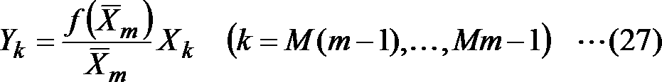
のように、区間内において音響信号もしくは周波数スペクトルXkに対して定数倍を行う。ここで、圧伸関数f(x)を例えば対数関数とし、代表値の決め方を二乗平均の平方根とすると、この変換はエネルギーの高い区間では小さい値による定数倍、エネルギーの低い区間では大きな値による定数倍に相当する。したがって、大きなサンプル値が多いほどその区間は変換により圧縮され、小さいサンプル値が多いほどその区間は変換により伸長される。また、同様の理由より、大きなサンプル値の近傍のサンプル値は小さいサンプル値の近傍のサンプル値よりも変換により圧縮される。
As described above, constant multiplication is performed on the acoustic signal or the frequency spectrum X k in the section. Here, if the companding function f (x) is a logarithmic function, for example, and the method of determining the representative value is the square root of the root mean square, this conversion is a constant multiple by a small value in a high energy interval, and a large value in a low energy interval. It corresponds to a constant multiple. Therefore, as the larger sample value is, the interval is compressed by the conversion, and as the smaller sample value is increased, the interval is expanded by the conversion. For the same reason, sample values near large sample values are compressed by conversion rather than sample values near small sample values.
復号装置には上記変換で生成された重み付信号もしくは重み付周波数スペクトルYkの値のみが伝わるため、一般的な決め方では代表値-Xmの値が求まらず、逆変換を行うことはできない。しかし、代表値を決める関数
Since only the value of the generated frequency spectrum with with signal or weighted weighted Y k by the conversion is transmitted to the decoding apparatus, a general representative value is how to determine - the value of X m is not Motomara, performing the inverse transform I can't. However, the function that determines the representative value
が絶対値平均のように1次の正斉次性を満たすのであれば、(つまり、
If satisfies the first order homogeneity like the absolute value average (that is,
である関数gが任意のα(>0)について
For any α (> 0) where the function g is
を満たすのであれば、)Ykの値から同じように代表値を求めると、
If the representative value is obtained in the same way from the value of Y k )

のように圧伸された代表値が得られる。この圧伸代表値を逆関数で変形することにより、
A representative value drawn as shown in FIG. By transforming this companding representative value with an inverse function,
のように復号装置でも元の代表値が求まる。この値を基に逆変換を
As described above, the original representative value can also be obtained by the decoding apparatus. Inverse transformation based on this value

のように行うことで、補助情報を使用せずに元のサンプル値を得ることができる。
By carrying out like this, the original sample value can be obtained without using auxiliary information.
もちろん圧伸の行われたYkが途中で量子化され、誤差が生じると元の代表値は正しく求まらないが、量子化されたYkに対して上記と同様な処理を行うことにより、代表値-Xmの推定値は算出でき、その値を基に逆変換を行うことができる。
Of course, the companded Y k is quantized in the middle, and if an error occurs, the original representative value cannot be obtained correctly, but by performing the same process as above on the quantized Y k , the representative value - estimated value of X m can be calculated, it is possible to perform inverse transform on the basis of its value.
<発明の効果>
上記のように構成することにより、この発明によれば、補助的な情報を追加することなく、音声音響信号に合わせて聴覚特性に適った重み付けを施し、不可逆圧縮符号化の効率を上げることができる。また、第五実施形態の構成によれば、準瞬時圧伸に用いる区間を低周波数では細かく、高周波数では粗く設定することにより、さらに聴覚特性に適った重み付けが実現できる。また、第六実施形態の構成によれば、異なる準瞬時圧伸を複数回用いることにより、より複雑な圧伸を実現し、重み付けの効率を上げることができる。 <Effect of the invention>
By configuring as described above, according to the present invention, weighting suitable for auditory characteristics can be performed according to the audio-acoustic signal without adding auxiliary information, and the efficiency of lossy compression coding can be increased. it can. Further, according to the configuration of the fifth embodiment, by setting the section used for the quasi-instantaneous companding to be fine at the low frequency and coarse at the high frequency, weighting more suitable for the auditory characteristics can be realized. Further, according to the configuration of the sixth embodiment, by using different quasi-instantaneous companding multiple times, more complicated companding can be realized and weighting efficiency can be increased.
以上、この発明の実施の形態について説明したが、具体的な構成は、これらの実施の形態に限られるものではなく、この発明の趣旨を逸脱しない範囲で適宜設計の変更等があっても、この発明に含まれることはいうまでもない。
As described above, the embodiments of the present invention have been described, but the specific configuration is not limited to these embodiments, and even if there is a design change or the like as appropriate without departing from the spirit of the present invention, Needless to say, it is included in this invention.
[プログラム、記録媒体]
上記実施形態で説明した各装置における各種の処理機能をコンピュータによって実現する場合、各装置が有すべき機能の処理内容はプログラムによって記述される。そして、このプログラムをコンピュータで実行することにより、上記各装置における各種の処理機能がコンピュータ上で実現される。 [Program, recording medium]
When various processing functions in each device described in the above embodiment are realized by a computer, the processing contents of the functions that each device should have are described by a program. Then, by executing this program on a computer, various processing functions in each of the above devices are realized on the computer.
この処理内容を記述したプログラムは、コンピュータで読み取り可能な記録媒体に記録しておくことができる。コンピュータで読み取り可能な記録媒体としては、例えば、磁気記録装置、光ディスク、光磁気記録媒体、半導体メモリ等どのようなものでもよい。
The program describing the processing contents can be recorded on a computer-readable recording medium. As the computer-readable recording medium, for example, any recording medium such as a magnetic recording device, an optical disk, a magneto-optical recording medium, and a semiconductor memory may be used.
また、このプログラムの流通は、例えば、そのプログラムを記録したDVD、CD-ROM等の可搬型記録媒体を販売、譲渡、貸与等することによって行う。さらに、このプログラムをサーバコンピュータの記憶装置に格納しておき、ネットワークを介して、サーバコンピュータから他のコンピュータにそのプログラムを転送することにより、このプログラムを流通させる構成としてもよい。
Also, this program is distributed, for example, by selling, transferring, or lending a portable recording medium such as a DVD or CD-ROM in which the program is recorded. Furthermore, the program may be distributed by storing the program in a storage device of the server computer and transferring the program from the server computer to another computer via a network.
このようなプログラムを実行するコンピュータは、例えば、まず、可搬型記録媒体に記録されたプログラムもしくはサーバコンピュータから転送されたプログラムを、一旦、自己の記憶装置に格納する。そして、処理の実行時、このコンピュータは、自己の記録媒体に格納されたプログラムを読み取り、読み取ったプログラムに従った処理を実行する。また、このプログラムの別の実行形態として、コンピュータが可搬型記録媒体から直接プログラムを読み取り、そのプログラムに従った処理を実行することとしてもよく、さらに、このコンピュータにサーバコンピュータからプログラムが転送されるたびに、逐次、受け取ったプログラムに従った処理を実行することとしてもよい。また、サーバコンピュータから、このコンピュータへのプログラムの転送は行わず、その実行指示と結果取得のみによって処理機能を実現する、いわゆるASP(Application Service Provider)型のサービスによって、上述の処理を実行する構成としてもよい。なお、本形態におけるプログラムには、電子計算機による処理の用に供する情報であってプログラムに準ずるもの(コンピュータに対する直接の指令ではないがコンピュータの処理を規定する性質を有するデータ等)を含むものとする。
For example, a computer that executes such a program first stores a program recorded on a portable recording medium or a program transferred from a server computer in its own storage device. When executing the process, this computer reads the program stored in its own recording medium and executes the process according to the read program. As another execution form of the program, the computer may directly read the program from a portable recording medium and execute processing according to the program, and the program is transferred from the server computer to the computer. Each time, the processing according to the received program may be executed sequentially. In addition, the program is not transferred from the server computer to the computer, and the above processing is executed by a so-called ASP (Application Service Provider) type service that realizes the processing function only by the execution instruction and result acquisition. It is good. Note that the program in this embodiment includes information that is used for processing by an electronic computer and that conforms to the program (data that is not a direct command to the computer but has a property that defines the processing of the computer).
また、この形態では、コンピュータ上で所定のプログラムを実行させることにより、本装置を構成することとしたが、これらの処理内容の少なくとも一部をハードウェア的に実現することとしてもよい。
In this embodiment, the present apparatus is configured by executing a predetermined program on a computer. However, at least a part of these processing contents may be realized by hardware.
Claims (17)
- 入力音響信号に対応する周波数領域信号を変形して得た重み付周波数領域信号を符号化する符号化装置に入力するための上記重み付周波数領域信号、または、入力音響信号に対応する周波数領域信号を変形して得た重み付周波数領域信号に対応する重み付時間領域信号を符号化する符号化装置に入力するための上記重み付時間領域信号に対応する重み付周波数領域信号、を得るサンプル列変形装置であって、
所定時間区間ごとに、入力音響信号に対応する周波数領域信号のサンプル列から、当該周波数領域信号のサンプル列の周波数サンプル数より少ない複数サンプルによる周波数区間ごとに、当該周波数区間に含まれるサンプルのサンプル値から当該周波数区間の代表値を算出する代表値算出部と、
上記所定時間区間ごとに、逆関数を定義できる圧伸関数による上記代表値の関数値に応じた重みと、上記周波数領域信号のサンプル列中の当該代表値に対応する各サンプルと、を乗算した周波数領域サンプル列を、上記重み付周波数領域信号のサンプル列として得る信号圧伸部と、
を含むサンプル列変形装置。 The above-mentioned weighted frequency domain signal to be input to an encoding device that encodes a weighted frequency domain signal obtained by transforming a frequency domain signal corresponding to the input acoustic signal, or a frequency domain signal corresponding to the input acoustic signal A sample sequence for obtaining a weighted frequency domain signal corresponding to the weighted time domain signal to be input to an encoding device for encoding a weighted time domain signal corresponding to the weighted frequency domain signal obtained by transforming A deformation device,
Samples of samples included in the frequency interval from a sample sequence of the frequency domain signal corresponding to the input acoustic signal for each frequency interval by a plurality of samples less than the number of frequency samples in the sample sequence of the frequency domain signal for each predetermined time interval A representative value calculation unit for calculating a representative value of the frequency section from the value;
For each predetermined time interval, the weight corresponding to the function value of the representative value by the companding function that can define an inverse function is multiplied by each sample corresponding to the representative value in the sample sequence of the frequency domain signal. A signal companding unit for obtaining a frequency domain sample sequence as a sample sequence of the weighted frequency domain signal;
Including sample row deformation device. - 復号装置が得た重み付周波数領域信号、または、復号装置が得た重み付時間領域信号に対応する重み付周波数領域信号、から復号音響信号に対応する周波数領域信号を得るサンプル列変形装置であって、
所定時間区間ごとに、上記重み付周波数領域信号のサンプル列から、当該重み付周波数領域信号のサンプル列の周波数サンプル数より少ない複数サンプルによる周波数区間ごとに当該周波数区間に含まれるサンプルのサンプル値から当該周波数区間の代表値を算出する圧伸代表値算出部と、
上記所定時間区間ごとに、逆関数を定義できる圧伸関数による上記代表値の関数値に応じた重みと、上記重み付周波数領域信号のサンプル列中の当該代表値に対応する各サンプルと、を乗算した周波数領域サンプル列を、上記復号音響信号に対応する周波数領域信号のサンプル列として得る信号逆圧伸部と、
を含むサンプル列変形装置。 A sample sequence transformation device that obtains a frequency domain signal corresponding to a decoded acoustic signal from a weighted frequency domain signal obtained by the decoding device or a weighted frequency domain signal corresponding to the weighted time domain signal obtained by the decoding device. And
From the sample sequence of the weighted frequency domain signal for each predetermined time interval, from the sample value of the sample included in the frequency segment for each frequency interval of a plurality of samples less than the number of frequency samples in the sample sequence of the weighted frequency domain signal A companding representative value calculating unit for calculating a representative value of the frequency section;
For each predetermined time interval, a weight according to the function value of the representative value by a companding function that can define an inverse function, and each sample corresponding to the representative value in the sample sequence of the weighted frequency domain signal, A signal back companding unit that obtains the multiplied frequency domain sample sequence as a sample sequence of the frequency domain signal corresponding to the decoded acoustic signal;
Including sample row deformation device. - 入力音響信号を変形して得た重み付音響信号を符号化する符号化装置に入力するための上記重み付音響信号、または、入力音響信号を変形して得た重み付音響信号に対応する重み付周波数領域信号を符号化する符号化装置に入力するための上記重み付周波数領域信号に対応する重み付音響信号、を得るサンプル列変形装置であって、
所定時間区間ごとに、時間領域の入力音響信号のサンプル列から、当該入力音響信号のサンプル列のサンプル数より少ない複数サンプルによる時間区間ごとに、当該時間区間に含まれるサンプルのサンプル値から当該時間区間の代表値を算出する代表値算出部と、
上記所定時間区間ごとに、逆関数を定義できる圧伸関数による上記代表値の関数値に応じた重みと、上記入力音響信号のサンプル列中の当該代表値に対応する各サンプルと、を乗算した時間領域サンプル列を、上記重み付音響信号のサンプル列として得る信号圧伸部と、
を含むサンプル列変形装置。 The weighted acoustic signal to be input to the encoding device that encodes the weighted acoustic signal obtained by transforming the input acoustic signal, or the weight corresponding to the weighted acoustic signal obtained by transforming the input acoustic signal A sample train deformation device for obtaining a weighted acoustic signal corresponding to the weighted frequency domain signal for input to an encoding device for encoding a weighted frequency domain signal,
For each predetermined time interval, from the sample sequence of the input acoustic signal in the time domain, for each time interval with a plurality of samples less than the number of samples in the sample sequence of the input acoustic signal, the time from the sample value of the sample included in the time interval A representative value calculation unit for calculating a representative value of the section;
For each predetermined time interval, the weight corresponding to the function value of the representative value by the companding function capable of defining an inverse function is multiplied by each sample corresponding to the representative value in the sample sequence of the input acoustic signal. A signal companding unit for obtaining a time-domain sample sequence as a sample sequence of the weighted acoustic signal;
Including sample row deformation device. - 復号装置が得た時間領域の重み付音響信号、または、復号装置が得た周波数領域の重み付音響信号に対応する時間領域の重み付音響信号、から復号音響信号を得るサンプル列変形装置であって、
所定時間区間ごとに、上記時間領域の重み付音響信号のサンプル列から、当該重み付音響信号のサンプル列のサンプル数より少ない複数サンプルによる時間区間ごとに、当該時間区間に含まれるサンプルのサンプル値から当該時間区間の代表値を算出する圧伸代表値算出部と、
上記所定時間区間ごとに、逆関数を定義できる圧伸関数による上記代表値の関数値に応じた重みと、上記重み付音響信号のサンプル列中の当該代表値に対応する各サンプルと、を乗算した時間領域サンプル列を、上記復号音響信号のサンプル列として得る信号逆圧伸部と、
を含むサンプル列変形装置。 A sample sequence transformation device that obtains a decoded acoustic signal from a time-domain weighted acoustic signal obtained by a decoding device or a time-domain weighted acoustic signal corresponding to a frequency-domain weighted acoustic signal obtained by a decoding device. And
For each predetermined time interval, from the sample sequence of the weighted acoustic signal in the time domain, the sample value of the sample included in the time interval for each time interval of a plurality of samples less than the number of samples in the sample sequence of the weighted acoustic signal A companding representative value calculation unit for calculating a representative value of the time interval from
Multiplying the weight corresponding to the function value of the representative value by the companding function that can define an inverse function and each sample corresponding to the representative value in the sample sequence of the weighted acoustic signal for each predetermined time interval A signal back companding unit that obtains the time domain sample sequence as a sample sequence of the decoded acoustic signal;
Including sample row deformation device. - 請求項1または2に記載のサンプル列変形装置であって、
上記複数サンプルによる周波数区間は、低周波数に対応する周波数区間であるほど含まれるサンプル数が少なく、高周波数に対応する周波数区間であるほど含まれるサンプル数が多くなるように設定される、
サンプル列変形装置。 The sample train deformation device according to claim 1 or 2,
The frequency interval by the plurality of samples is set so that the number of samples included is smaller as the frequency interval corresponds to the low frequency, and the number of samples included is higher as the frequency interval corresponds to the high frequency.
Sample row deformation device. - 請求項1から5のいずれかに記載のサンプル列変形装置であって、
上記複数サンプルによる区間ごとに上記代表値を算出することと、上記算出した代表値の関数値に応じた重みと上記サンプル列の各サンプルとを乗算することを、所定の回数繰り返し実行するものである、
サンプル列変形装置。 The sample train deformation device according to any one of claims 1 to 5,
The calculation of the representative value for each section of the plurality of samples and the multiplication of the weights corresponding to the calculated function value of the representative value by each sample of the sample sequence are repeatedly executed a predetermined number of times. is there,
Sample row deformation device. - 請求項1または3に記載のサンプル列変形装置であって、
上記所定時間区間ごとに、入力音響信号または入力音響信号に対応する周波数領域信号を目標符号長で符号化するための量子化幅を得る量子化幅算出部と、
上記所定時間区間ごとに、上記圧伸関数として、
上記量子化幅が小さいほど、上記入力音響信号と上記重み付音響信号、または、上記入力音響信号に対応する周波数領域信号のサンプル列と上記重み付周波数領域信号のサンプル列、が近くなる、
または/および、
上記量子化幅が大きいほど、上記重み付音響信号または上記重み付周波数領域信号のサンプル列のパワーが平坦になる、
圧伸関数を選択する圧伸関数選択部と、
を更に含むサンプル列変形装置。 The sample train deformation device according to claim 1 or 3,
For each of the predetermined time intervals, a quantization width calculation unit that obtains a quantization width for encoding the input acoustic signal or a frequency domain signal corresponding to the input acoustic signal with a target code length;
For each predetermined time interval, as the companding function,
The smaller the quantization width, the closer the input acoustic signal and the weighted acoustic signal, or the sample sequence of the frequency domain signal corresponding to the input acoustic signal and the sample sequence of the weighted frequency domain signal,
Or / and
The greater the quantization width, the flatter the power of the weighted acoustic signal or the weighted frequency domain signal sample sequence,
A companding function selector for selecting the companding function;
A sample row deformation device further comprising: - 請求項1または3に記載のサンプル列変形装置と、符号化対象信号を符号化して信号符号を得る符号化装置と、を含む信号符号化装置であって、
上記所定時間区間ごとに、入力音響信号または入力音響信号に対応する周波数領域信号を目標符号長で符号化するための量子化幅を得て、
得られた量子化幅が所定の閾値より小さいまたは所定の閾値以下である時間区間については、上記入力音響信号または上記入力音響信号に対応する周波数領域信号を上記符号化対象信号として上記符号化装置で符号化し、
それ以外の時間区間については、上記入力音響信号または上記入力音響信号に対応する周波数領域信号を上記サンプル列変形装置に入力し、上記サンプル列変形装置が得た上記重み付音響信号または上記重み付周波数領域信号のサンプル列を上記符号化対象信号として上記符号化装置で符号化する
信号符号化装置。 A signal encoding device comprising: the sample string transformation device according to claim 1 or 3; and an encoding device that encodes a signal to be encoded to obtain a signal code,
For each predetermined time interval, obtain a quantization width for encoding an input acoustic signal or a frequency domain signal corresponding to the input acoustic signal with a target code length,
For the time interval in which the obtained quantization width is smaller than a predetermined threshold or less than or equal to a predetermined threshold, the encoding device uses the input acoustic signal or a frequency domain signal corresponding to the input acoustic signal as the encoding target signal. Encoded with
For the other time intervals, the input acoustic signal or the frequency domain signal corresponding to the input acoustic signal is input to the sample train deforming device, and the weighted acoustic signal or weighting obtained by the sample train transforming device is obtained. A signal encoding device that encodes a sample sequence of a frequency domain signal as the encoding target signal by the encoding device. - 請求項2または4に記載のサンプル列変形装置と、信号符号を復号して復号信号を得る復号装置と、を含む信号復号装置であって、
上記所定時間区間ごとに、量子化幅符号を復号して量子化幅を得て、
得られた量子化幅が所定の閾値より小さいまたは所定の閾値以下である時間区間については、上記信号符号を上記復号装置で復号して得た信号を上記復号音響信号または上記復号音響信号に対応する周波数領域信号として得、
それ以外の時間区間については、上記復号装置が得た信号を上記サンプル列変形装置に入力して上記復号音響信号または上記復号音響信号に対応する周波数領域信号を得る
信号復号装置。 A signal decoding device comprising: the sample string transformation device according to claim 2; and a decoding device that decodes a signal code to obtain a decoded signal,
For each predetermined time interval, the quantization width code is decoded to obtain the quantization width,
For a time interval in which the obtained quantization width is smaller than a predetermined threshold value or less than a predetermined threshold value, the signal obtained by decoding the signal code by the decoding device corresponds to the decoded acoustic signal or the decoded acoustic signal. Obtained as a frequency domain signal
For other time intervals, the signal obtained by the decoding device is input to the sample string transformation device to obtain the decoded acoustic signal or a frequency domain signal corresponding to the decoded acoustic signal. - 入力音響信号に対応する周波数領域信号を変形して得た重み付周波数領域信号を符号化する符号化方法に入力するための上記重み付周波数領域信号、または、入力音響信号に対応する周波数領域信号を変形して得た重み付周波数領域信号に対応する重み付時間領域信号を符号化する符号化方法に入力するための上記重み付時間領域信号に対応する重み付周波数領域信号、を得るサンプル列変形方法であって、
所定時間区間ごとに、入力音響信号に対応する周波数領域信号のサンプル列から、当該周波数領域信号のサンプル列の周波数サンプル数より少ない複数サンプルによる周波数区間ごとに、当該周波数区間に含まれるサンプルのサンプル値から当該周波数区間の代表値を算出する代表値算出ステップと、
上記所定時間区間ごとに、逆関数を定義できる圧伸関数による上記代表値の関数値に応じた重みと、上記周波数領域信号のサンプル列中の当該代表値に対応する各サンプルと、を乗算した周波数領域サンプル列を、上記重み付周波数領域信号のサンプル列として得る信号圧伸ステップと、
を含むサンプル列変形方法。 The above-mentioned weighted frequency domain signal for input to an encoding method for encoding a weighted frequency domain signal obtained by transforming a frequency domain signal corresponding to the input acoustic signal, or a frequency domain signal corresponding to the input acoustic signal A sample sequence for obtaining a weighted frequency domain signal corresponding to the weighted time domain signal to be input to an encoding method for encoding a weighted time domain signal corresponding to the weighted frequency domain signal obtained by transforming A deformation method,
Samples of samples included in the frequency interval from a sample sequence of the frequency domain signal corresponding to the input acoustic signal for each frequency interval by a plurality of samples less than the number of frequency samples in the sample sequence of the frequency domain signal for each predetermined time interval A representative value calculating step for calculating a representative value of the frequency section from the value;
For each predetermined time interval, the weight corresponding to the function value of the representative value by the companding function that can define an inverse function is multiplied by each sample corresponding to the representative value in the sample sequence of the frequency domain signal. A signal companding step of obtaining a frequency domain sample sequence as a sample sequence of the weighted frequency domain signal;
A sample column transformation method including: - 復号により得た重み付周波数領域信号、または、復号により得た重み付時間領域信号に対応する重み付周波数領域信号、から復号音響信号に対応する周波数領域信号を得るサンプル列変形方法であって、
所定時間区間ごとに、上記重み付周波数領域信号のサンプル列から、当該重み付周波数領域信号のサンプル列の周波数サンプル数より少ない複数サンプルによる周波数区間ごとに当該周波数区間に含まれるサンプルのサンプル値から当該周波数区間の代表値を算出する圧伸代表値算出ステップと、
上記所定時間区間ごとに、逆関数を定義できる圧伸関数による上記代表値の関数値に応じた重みと、上記重み付周波数領域信号のサンプル列中の当該代表値に対応する各サンプルと、を乗算した周波数領域サンプル列を、上記復号音響信号に対応する周波数領域信号のサンプル列として得る信号逆圧伸ステップと、
を含むサンプル列変形方法。 A sample sequence modification method for obtaining a frequency domain signal corresponding to a decoded acoustic signal from a weighted frequency domain signal obtained by decoding or a weighted frequency domain signal corresponding to a weighted time domain signal obtained by decoding,
From the sample sequence of the weighted frequency domain signal for each predetermined time interval, from the sample value of the sample included in the frequency segment for each frequency interval of a plurality of samples less than the number of frequency samples in the sample sequence of the weighted frequency domain signal Companding representative value calculating step for calculating a representative value of the frequency section;
For each predetermined time interval, a weight according to the function value of the representative value by a companding function that can define an inverse function, and each sample corresponding to the representative value in the sample sequence of the weighted frequency domain signal, A signal reverse companding step of obtaining a multiplied frequency domain sample sequence as a sample sequence of a frequency domain signal corresponding to the decoded acoustic signal;
A sample column transformation method including: - 入力音響信号を変形して得た重み付音響信号を符号化する符号化方法に入力するための上記重み付音響信号、または、入力音響信号を変形して得た重み付音響信号に対応する重み付周波数領域信号を符号化する符号化方法に入力するための上記重み付周波数領域信号に対応する重み付音響信号、を得るサンプル列変形方法であって、
所定時間区間ごとに、時間領域の入力音響信号のサンプル列から、当該入力音響信号のサンプル列のサンプル数より少ない複数サンプルによる時間区間ごとに、当該時間区間に含まれるサンプルのサンプル値から当該時間区間の代表値を算出する代表値算出ステップと、
上記所定時間区間ごとに、逆関数を定義できる圧伸関数による上記代表値の関数値に応じた重みと、上記入力音響信号のサンプル列中の当該代表値に対応する各サンプルと、を乗算した時間領域サンプル列を、上記重み付音響信号のサンプル列として得る信号圧伸ステップと、
を含むサンプル列変形方法。 The weighted sound signal for input to the encoding method for encoding the weighted sound signal obtained by modifying the input sound signal, or the weight corresponding to the weighted sound signal obtained by modifying the input sound signal A sample sequence modification method for obtaining a weighted acoustic signal corresponding to the weighted frequency domain signal for input to an encoding method for encoding a weighted frequency domain signal,
For each predetermined time interval, from the sample sequence of the input acoustic signal in the time domain, for each time interval with a plurality of samples less than the number of samples in the sample sequence of the input acoustic signal, the time from the sample value of the sample included in the time interval A representative value calculating step for calculating a representative value of the section;
For each predetermined time interval, the weight corresponding to the function value of the representative value by the companding function capable of defining an inverse function is multiplied by each sample corresponding to the representative value in the sample sequence of the input acoustic signal. A signal companding step of obtaining a time domain sample sequence as a sample sequence of the weighted acoustic signal;
A sample column transformation method including: - 復号により得た時間領域の重み付音響信号、または、復号により得た周波数領域の重み付音響信号に対応する時間領域の重み付音響信号、から復号音響信号を得るサンプル列変形方法であって、
所定時間区間ごとに、上記時間領域の重み付音響信号のサンプル列から、当該重み付音響信号のサンプル列のサンプル数より少ない複数サンプルによる時間区間ごとに、当該時間区間に含まれるサンプルのサンプル値から当該時間区間の代表値を算出する圧伸代表値算出ステップと、
上記所定時間区間ごとに、逆関数を定義できる圧伸関数による上記代表値の関数値に応じた重みと、上記重み付音響信号のサンプル列中の当該代表値に対応する各サンプルと、を乗算した時間領域サンプル列を、上記復号音響信号のサンプル列として得る信号逆圧伸ステップと、
を含むサンプル列変形方法。 A sample sequence modification method for obtaining a decoded acoustic signal from a time-domain weighted acoustic signal obtained by decoding or a time-domain weighted acoustic signal corresponding to a frequency-domain weighted acoustic signal obtained by decoding,
For each predetermined time interval, from the sample sequence of the weighted acoustic signal in the time domain, the sample value of the sample included in the time interval for each time interval of a plurality of samples less than the number of samples in the sample sequence of the weighted acoustic signal A companding representative value calculating step for calculating a representative value of the time interval from
Multiplying the weight corresponding to the function value of the representative value by the companding function that can define an inverse function and each sample corresponding to the representative value in the sample sequence of the weighted acoustic signal for each predetermined time interval A signal reverse companding step for obtaining the time domain sample sequence as a sample sequence of the decoded acoustic signal;
A sample column transformation method including: - 請求項10または12に記載のサンプル列変形方法であって、
上記所定時間区間ごとに、入力音響信号または入力音響信号に対応する周波数領域信号を目標符号長で符号化するための量子化幅を得る量子化幅算出ステップと、
上記所定時間区間ごとに、上記圧伸関数として、
上記量子化幅が小さいほど、上記入力音響信号と上記重み付音響信号、または、上記入力音響信号に対応する周波数領域信号のサンプル列と上記重み付周波数領域信号のサンプル列、が近くなる、
または/および、
上記量子化幅が大きいほど、上記重み付音響信号または上記重み付周波数領域信号のサンプル列のパワーが平坦になる、
圧伸関数を選択する圧伸関数選択ステップと、
を更に含むサンプル列変形方法。 The sample sequence deformation method according to claim 10 or 12,
A quantization width calculation step for obtaining a quantization width for encoding the input acoustic signal or a frequency domain signal corresponding to the input acoustic signal with a target code length for each predetermined time interval;
For each predetermined time interval, as the companding function,
The smaller the quantization width, the closer the input acoustic signal and the weighted acoustic signal, or the sample sequence of the frequency domain signal corresponding to the input acoustic signal and the sample sequence of the weighted frequency domain signal,
Or / and
The greater the quantization width, the flatter the power of the weighted acoustic signal or the weighted frequency domain signal sample sequence,
A companding function selection step for selecting the companding function;
A sample row deformation method further comprising: - 請求項10または12に記載のサンプル列変形方法と、符号化対象信号を符号化して信号符号を得る符号化方法と、を含む信号符号化方法であって、
上記所定時間区間ごとに、入力音響信号または入力音響信号に対応する周波数領域信号を目標符号長で符号化するための量子化幅を得て、
得られた量子化幅が所定の閾値より小さいまたは所定の閾値以下である時間区間については、上記入力音響信号または上記入力音響信号に対応する周波数領域信号を上記符号化対象信号として上記符号化方法で符号化し、
それ以外の時間区間については、上記入力音響信号または上記入力音響信号に対応する周波数領域信号を上記サンプル列変形方法に入力し、上記サンプル列変形方法が得た上記重み付音響信号または上記重み付周波数領域信号のサンプル列を上記符号化対象信号として上記符号化方法で符号化する
信号符号化方法。 A signal encoding method comprising: the sample string transformation method according to claim 10 or 12; and an encoding method for encoding a signal to be encoded to obtain a signal code,
For each predetermined time interval, obtain a quantization width for encoding an input acoustic signal or a frequency domain signal corresponding to the input acoustic signal with a target code length,
For the time interval in which the obtained quantization width is smaller than a predetermined threshold value or less than a predetermined threshold value, the encoding method uses the input acoustic signal or a frequency domain signal corresponding to the input acoustic signal as the encoding target signal. Encoded with
For the other time intervals, the input acoustic signal or the frequency domain signal corresponding to the input acoustic signal is input to the sample sequence transformation method, and the weighted acoustic signal or the weighted weight obtained by the sample sequence transformation method is obtained. A signal encoding method in which a sample sequence of a frequency domain signal is encoded by the encoding method as the encoding target signal. - 請求項11または13に記載のサンプル列変形方法と、信号符号を復号して復号信号を得る復号方法と、を含む信号復号方法であって、
上記所定時間区間ごとに、量子化幅符号を復号して量子化幅を得て、
得られた量子化幅が所定の閾値より小さいまたは所定の閾値以下である時間区間については、上記信号符号を上記復号装置で復号して得た信号を上記復号音響信号または上記復号音響信号に対応する周波数領域信号として得、
それ以外の時間区間については、上記復号装置が得た信号を上記サンプル列変形方法に入力して上記復号音響信号または上記復号音響信号に対応する周波数領域信号を得る
信号復号方法。 A signal decoding method comprising: the sample string transformation method according to claim 11 or 13; and a decoding method for decoding a signal code to obtain a decoded signal,
For each predetermined time interval, the quantization width code is decoded to obtain the quantization width,
For a time interval in which the obtained quantization width is smaller than a predetermined threshold value or less than a predetermined threshold value, the signal obtained by decoding the signal code by the decoding device corresponds to the decoded acoustic signal or the decoded acoustic signal. Obtained as a frequency domain signal
For other time intervals, the signal obtained by the decoding device is input to the sample string transformation method to obtain the decoded acoustic signal or a frequency domain signal corresponding to the decoded acoustic signal. - 請求項1から7のいずれかに記載のサンプル列変形装置または請求項8に記載の信号符号化装置または請求項9に記載の信号復号装置としてコンピュータを機能させるためのプログラム。 A program for causing a computer to function as the sample string transformation device according to any one of claims 1 to 7, the signal encoding device according to claim 8, or the signal decoding device according to claim 9.
Priority Applications (4)
| Application Number | Priority Date | Filing Date | Title |
|---|---|---|---|
| EP17850905.5A EP3514791B1 (en) | 2016-09-15 | 2017-09-13 | Sample sequence converter, sample sequence converting method and program |
| JP2018539738A JP6712643B2 (en) | 2016-09-15 | 2017-09-13 | Sample sequence transformation device, signal coding device, signal decoding device, sample sequence transformation method, signal coding method, signal decoding method, and program |
| CN201780056241.XA CN109716431B (en) | 2016-09-15 | 2017-09-13 | Sample string deforming device, sample string deforming method, and recording medium |
| US16/332,583 US11468905B2 (en) | 2016-09-15 | 2017-09-13 | Sample sequence converter, signal encoding apparatus, signal decoding apparatus, sample sequence converting method, signal encoding method, signal decoding method and program |
Applications Claiming Priority (4)
| Application Number | Priority Date | Filing Date | Title |
|---|---|---|---|
| JP2016180196 | 2016-09-15 | ||
| JP2016-180196 | 2016-09-15 | ||
| JP2017001966 | 2017-01-10 | ||
| JP2017-001966 | 2017-01-10 |
Publications (1)
| Publication Number | Publication Date |
|---|---|
| WO2018052004A1 true WO2018052004A1 (en) | 2018-03-22 |
Family
ID=61618807
Family Applications (1)
| Application Number | Title | Priority Date | Filing Date |
|---|---|---|---|
| PCT/JP2017/032991 WO2018052004A1 (en) | 2016-09-15 | 2017-09-13 | Sample string transformation device, signal encoding device, signal decoding device, sample string transformation method, signal encoding method, signal decoding method, and program |
Country Status (5)
| Country | Link |
|---|---|
| US (1) | US11468905B2 (en) |
| EP (1) | EP3514791B1 (en) |
| JP (1) | JP6712643B2 (en) |
| CN (1) | CN109716431B (en) |
| WO (1) | WO2018052004A1 (en) |
Citations (4)
| Publication number | Priority date | Publication date | Assignee | Title |
|---|---|---|---|---|
| JPH05158495A (en) * | 1991-05-07 | 1993-06-25 | Fujitsu Ltd | Voice encoding transmitter |
| JP2002123298A (en) * | 2000-10-18 | 2002-04-26 | Nippon Telegr & Teleph Corp <Ntt> | Method and device for encoding signal, recording medium recorded with signal encoding program |
| JP2002353820A (en) * | 2001-05-22 | 2002-12-06 | Sony Corp | Normalizing device, method, program and recording medium with the program recorded, and communication terminal equipment |
| JP2009230154A (en) * | 1997-12-08 | 2009-10-08 | Mitsubishi Electric Corp | Sound signal processing device and sound signal processing method |
Family Cites Families (4)
| Publication number | Priority date | Publication date | Assignee | Title |
|---|---|---|---|---|
| US7548853B2 (en) * | 2005-06-17 | 2009-06-16 | Shmunk Dmitry V | Scalable compressed audio bit stream and codec using a hierarchical filterbank and multichannel joint coding |
| JP5694751B2 (en) * | 2010-12-13 | 2015-04-01 | 日本電信電話株式会社 | Encoding method, decoding method, encoding device, decoding device, program, recording medium |
| ES2617958T3 (en) * | 2011-04-05 | 2017-06-20 | Nippon Telegraph And Telephone Corporation | Coding of an acoustic signal |
| KR101762204B1 (en) * | 2012-05-23 | 2017-07-27 | 니폰 덴신 덴와 가부시끼가이샤 | Encoding method, decoding method, encoder, decoder, program and recording medium |
-
2017
- 2017-09-13 WO PCT/JP2017/032991 patent/WO2018052004A1/en unknown
- 2017-09-13 EP EP17850905.5A patent/EP3514791B1/en active Active
- 2017-09-13 CN CN201780056241.XA patent/CN109716431B/en active Active
- 2017-09-13 JP JP2018539738A patent/JP6712643B2/en active Active
- 2017-09-13 US US16/332,583 patent/US11468905B2/en active Active
Patent Citations (4)
| Publication number | Priority date | Publication date | Assignee | Title |
|---|---|---|---|---|
| JPH05158495A (en) * | 1991-05-07 | 1993-06-25 | Fujitsu Ltd | Voice encoding transmitter |
| JP2009230154A (en) * | 1997-12-08 | 2009-10-08 | Mitsubishi Electric Corp | Sound signal processing device and sound signal processing method |
| JP2002123298A (en) * | 2000-10-18 | 2002-04-26 | Nippon Telegr & Teleph Corp <Ntt> | Method and device for encoding signal, recording medium recorded with signal encoding program |
| JP2002353820A (en) * | 2001-05-22 | 2002-12-06 | Sony Corp | Normalizing device, method, program and recording medium with the program recorded, and communication terminal equipment |
Non-Patent Citations (4)
| Title |
|---|
| "Lossless compression of G.711 pulse code modulation", ITU-T G.711.0, 2009 |
| GERALD D. T. SCHULLER; BIN YU; DAWEI HUANG; BERND EDLER: "Perceptual Audio Coding Using Adaptive Pre-and Post-Filters and Lossless Compression", IEEE TRANSACTIONS ON SPEECH AND AUDIO PROCESSING, vol. 10, no. 6, September 2002 (2002-09-01), XP011079662 |
| See also references of EP3514791A4 |
| T. LIEBECHEN; T. MORIYA; N. HARADA; Y. KAMAMOTO; Y. A. REZNIK: "The MPEG-4 Audio Lossless Coding (ALS) standard - technology and applications", PROC. AES 119TH CONVENTION, October 2005 (2005-10-01) |
Also Published As
| Publication number | Publication date |
|---|---|
| EP3514791A1 (en) | 2019-07-24 |
| JP6712643B2 (en) | 2020-06-24 |
| CN109716431A (en) | 2019-05-03 |
| EP3514791B1 (en) | 2021-07-28 |
| EP3514791A4 (en) | 2020-04-29 |
| JPWO2018052004A1 (en) | 2019-07-04 |
| US11468905B2 (en) | 2022-10-11 |
| US20210335372A1 (en) | 2021-10-28 |
| CN109716431B (en) | 2022-11-01 |
Similar Documents
| Publication | Publication Date | Title |
|---|---|---|
| KR102248252B1 (en) | Method and apparatus for encoding and decoding high frequency for bandwidth extension | |
| CN101622662B (en) | Encoding device and encoding method | |
| EP0942411B1 (en) | Audio signal coding and decoding apparatus | |
| JP3344962B2 (en) | Audio signal encoding device and audio signal decoding device | |
| JP3636094B2 (en) | Signal encoding apparatus and method, and signal decoding apparatus and method | |
| JP4978539B2 (en) | Encoding apparatus, encoding method, and program. | |
| US20130101028A1 (en) | Encoding method, decoding method, device, program, and recording medium | |
| US20130101049A1 (en) | Encoding method, decoding method, encoding device, decoding device, program, and recording medium | |
| US20130106626A1 (en) | Encoding method, decoding method, encoding device, decoding device, program, and recording medium | |
| WO2018052004A1 (en) | Sample string transformation device, signal encoding device, signal decoding device, sample string transformation method, signal encoding method, signal decoding method, and program | |
| JP4191503B2 (en) | Speech musical sound signal encoding method, decoding method, encoding device, decoding device, encoding program, and decoding program | |
| JP3353266B2 (en) | Audio signal conversion coding method | |
| JP3353267B2 (en) | Audio signal conversion encoding method and decoding method | |
| WO2023278889A1 (en) | Compressing audio waveforms using neural networks and vector quantizers | |
| JP2011009868A (en) | Encoding method, decoding method, encoder, decoder, and program | |
| JP2000132195A (en) | Signal encoding device and method therefor | |
| JPH1091196A (en) | Method of encoding acoustic signal and method of decoding acoustic signal |
Legal Events
| Date | Code | Title | Description |
|---|---|---|---|
| 121 | Ep: the epo has been informed by wipo that ep was designated in this application |
Ref document number: 17850905 Country of ref document: EP Kind code of ref document: A1 |
|
| ENP | Entry into the national phase |
Ref document number: 2018539738 Country of ref document: JP Kind code of ref document: A |
|
| NENP | Non-entry into the national phase |
Ref country code: DE |
|
| ENP | Entry into the national phase |
Ref document number: 2017850905 Country of ref document: EP Effective date: 20190415 |