WO2018047600A1 - Grinding stone and production method therefor - Google Patents
Grinding stone and production method therefor Download PDFInfo
- Publication number
- WO2018047600A1 WO2018047600A1 PCT/JP2017/029594 JP2017029594W WO2018047600A1 WO 2018047600 A1 WO2018047600 A1 WO 2018047600A1 JP 2017029594 W JP2017029594 W JP 2017029594W WO 2018047600 A1 WO2018047600 A1 WO 2018047600A1
- Authority
- WO
- WIPO (PCT)
- Prior art keywords
- base metal
- fixed
- grinding
- fixed abrasive
- workpiece
- Prior art date
Links
Images


Classifications
-
- B—PERFORMING OPERATIONS; TRANSPORTING
- B24—GRINDING; POLISHING
- B24D—TOOLS FOR GRINDING, BUFFING OR SHARPENING
- B24D3/00—Physical features of abrasive bodies, or sheets, e.g. abrasive surfaces of special nature; Abrasive bodies or sheets characterised by their constituents
-
- B—PERFORMING OPERATIONS; TRANSPORTING
- B24—GRINDING; POLISHING
- B24D—TOOLS FOR GRINDING, BUFFING OR SHARPENING
- B24D5/00—Bonded abrasive wheels, or wheels with inserted abrasive blocks, designed for acting only by their periphery; Bushings or mountings therefor
-
- B—PERFORMING OPERATIONS; TRANSPORTING
- B24—GRINDING; POLISHING
- B24D—TOOLS FOR GRINDING, BUFFING OR SHARPENING
- B24D3/00—Physical features of abrasive bodies, or sheets, e.g. abrasive surfaces of special nature; Abrasive bodies or sheets characterised by their constituents
- B24D3/02—Physical features of abrasive bodies, or sheets, e.g. abrasive surfaces of special nature; Abrasive bodies or sheets characterised by their constituents the constituent being used as bonding agent
- B24D3/04—Physical features of abrasive bodies, or sheets, e.g. abrasive surfaces of special nature; Abrasive bodies or sheets characterised by their constituents the constituent being used as bonding agent and being essentially inorganic
Definitions
- the present invention relates to a grinding wheel used for grinding a workpiece made of a metal material, a ceramic material or the like, and a method of manufacturing the same.
- a grinding wheel for grinding a workpiece made of a metal material, a ceramic material or the like for example, a base metal having a workpiece facing surface facing the workpiece, and abrasive grains such as diamond or cBN on the workpiece facing surface are suitable. It is known to have an abrasive layer or grinding layer held by a bonding material (see Patent Document 1). Then, when grinding a work using such a grinding wheel, the grinding wheel is attached to a suitable grinding device, and the base metal is fed at a high speed while rotating around its axis to feed it toward the work, The grinding layer disposed on the workpiece facing surface of the base metal is brought into contact with the workpiece. By doing so, the abrasive grains exposed on the surface of the grinding layer become cutting edges, and the work is ground.
- JP, 2010-46771 A Japanese Patent Application Laid-Open No. 63-283865
- the technical subject of this invention is excellent in the discharge
- the present invention has a base metal having a workpiece facing surface for facing a workpiece, and a fixed abrasive wire in which a large number of abrasive grains are fixed to a core wire,
- the abrasive wire is fixed so as to extend adjacent to the workpiece facing surface of the base metal, whereby a grinding portion for workpiece grinding is formed on the workpiece facing surface, and adjacent fixed abrasive particles are formed.
- a grinding wheel characterized in that a discharge groove for chip discharge, which is a recess between wires, is formed.
- the workpiece-facing surface of the base metal is formed of an outer peripheral surface around the rotation axis of the base metal, and the fixed abrasive wire is formed on the outer peripheral surface of the base metal along the rotational axis direction.
- the fixed abrasive wire which is fixed to the base metal in a spirally wound state, whereby the grinding portion is formed on the outer peripheral surface of the base metal and adjacent to the rotation axis direction.
- the discharge groove is formed by the concave portion of And, more preferably, the fixed abrasive wire has a first end and a second end at both ends in the longitudinal direction, and the first end is fixed to one end side of the base metal in the rotation axis direction The second end is fixed to the other end side of the base metal in the direction of the rotation axis of the base metal, and the intermediate part located between the first end and the second end is the base metal. Relative to the outer peripheral surface, it is wound so as to be capable of relative movement in the direction of the rotation axis in a non-sticking state.
- the work-facing surface of the base metal is an end face on one end side in the rotation axis direction of the base metal, and the fixed abrasive wire is on the end face of the base metal.
- the grinding portion is formed on the end face of the base metal, and the radial direction of the base metal is fixed to the base metal in a spirally wound state around the rotation axis.
- the said discharge groove may be formed of the recessed part between the fixed abrasive wires which adjoin each other.
- the fixed abrasive wire has a first end and a second end at both ends in the longitudinal direction, and the first end is on one side in the radial direction of the end face of the base metal.
- An intermediate portion which is fixed, the second end is fixed on the other side in the radial direction of the base metal, and an intermediate portion located between the first end and the second end is opposed to the end face of the base metal.
- a spirally recessed guide groove is engraved on the end face of the base metal, and the fixed abrasive wire is disposed in the guide groove along the longitudinal direction of the guide groove. It may be fixed to the base metal in a fixed state.
- a grinding wheel in which a grinding portion for grinding a workpiece and a discharge groove for discharging chips are formed on the workpiece-facing surface of a base metal having a workpiece-facing surface for facing a workpiece.
- a fixed abrasive wire having an outer peripheral surface around the rotation axis of the base metal as the work-facing surface, and a fixed abrasive wire having abrasive grains fixed to the core wire is formed on the outer peripheral surface of the base metal in the rotational axis direction.
- the grinding portion is formed on the outer peripheral surface by spirally winding from one end side to the other end side, and the discharge groove is formed by the concave portion between the fixed abrasive wires adjacent in the rotation axis direction.
- a method of manufacturing a grinding wheel comprising the steps of forming and securing the first end and the second end in the longitudinal direction of the fixed abrasive wire to the base metal.
- a method of manufacturing a grinding stone in which a grinding portion for grinding a workpiece and a discharge groove for discharging chips are formed on the workpiece-facing surface of a base metal having a workpiece-facing surface facing a workpiece.
- the fixed abrasive wire having an end face on one end side in the rotation axis direction of the base metal as the work-facing surface and the abrasive grains fixed to the core wire is placed on the end face of the base metal around its rotation axis.
- a method of manufacturing a grinding wheel characterized by the present invention is provided.
- the fixed abrasive wire is fixed to the workpiece facing surface facing the workpiece in the base metal, whereby the grinding portion and chips for grinding the workpiece on the workpiece facing surface of the base metal A discharge groove for discharge is simultaneously formed. Therefore, it is possible to provide a grinding wheel which is excellent in chip dischargeability and can improve the grinding efficiency, and a method of manufacturing the grinding wheel.
- FIG. 2 is a partial enlarged side view schematically showing an area A surrounded by an alternate long and short dash line in FIG.
- FIG. 2 is a partial enlarged side view schematically showing a region B surrounded by an alternate long and short dash line in FIG. 1.
- FIG. 1 It is a top view which shows typically 2nd Embodiment of the grinding stone which concerns on this invention.
- FIG. 7 is a partially enlarged cross-sectional view showing an intermediate portion of the fixed abrasive wire fixed to the base metal of FIG. 6 in an enlarged manner.
- FIG. 7 is a partial enlarged plan view schematically showing a region C surrounded by an alternate long and short dash line in FIG. 6.
- FIG. 7 is a partial enlarged plan view schematically showing a region D surrounded by an alternate long and short dash line in FIG. 6. It is a top view which shows typically 3rd Embodiment of the grinding stone which concerns on this invention.
- FIG. 11 is a partially enlarged cross-sectional view showing an intermediate portion of the fixed abrasive wire fixed to the base metal of FIG. 10 in an enlarged manner.
- FIG. 11 is a partial enlarged plan view schematically showing an area E surrounded by an alternate long and short dash line in FIG. 10.
- FIG. 11 is a partial enlarged plan view schematically showing a region F surrounded by an alternate long and short dash line in FIG. 10.
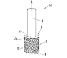
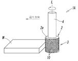
- the grinding wheel 1A is for grinding a workpiece W such as a metal material or a ceramic, and the base metal 2 having a workpiece facing surface facing the workpiece W, and the workpiece grinding surface provided on the workpiece facing surface And a grinding unit 3.
- the base metal 2 was attached to a suitable grinding device (not shown) and was rotated about its rotation axis L with respect to the base metal 2 Feeding is performed in a state, and the grinding portion 3 provided on the work grinding surface of the base metal 2 (the outer peripheral surface 2a of the base metal 2 described later) is brought into contact with the work W.
- the base metal 2 is formed in a cylindrical or cylindrical shape and formed in a circular cross-section, for example, by a metal such as stainless steel, aluminum, super steel, etc.
- the work opposing surface is the base metal. It comprises a circular outer peripheral surface 2a around the rotation axis L.
- the base metal 2 is integrally provided with a shaft 4 formed in a round rod shape smaller in diameter than that.
- the shaft 4 is a portion to be clamped by the grinding device.
- the base metal 2 is attached to the grinding apparatus through the shaft 4 so that it can rotate in the three axial directions while rotating about the axis L by the driving force of the grinding apparatus.
- the outer diameters of the base metal 2 and the shaft 4 and the lengths in the direction of the rotation axis L can be arbitrarily set in accordance with the dimensions of the workpiece to be ground.
- the fixed abrasive wire 10 having flexibility described later spirals along the direction of the rotation axis L on the outer peripheral surface 2 a of the base metal 2. It is formed by being fixed to the base metal 2 in a wound state. And the abrasive grain 11 exposed to the surface of the fixed abrasive wire 10 becomes a cutting blade, and the said workpiece
- the fixed abrasive wire 10 used for the grinding wheel 1A fine wires such as diamond or cubic boron nitride (cBN) can be used as the core wire 12 made of metal such as piano wire and having flexibility.
- the abrasive grains 11 are fixed in a single layer state (single particle state).
- fixing of the abrasive grains 11 to the core wire 12 is performed by an appropriate fixing method, but when the abrasive grains 11 are fixed in a single layer state on the core wire 12 as in the present embodiment, Since the spontaneous growth effect of the abrasive grains 11 does not occur, when the abrasive grains 11 are disintegrated, the sharpness in the disaggregated portion becomes dull.
- the retention strength of the abrasive grains 11 to the core wire 12 is enhanced. ing. Therefore, it is possible to suppress the dropout of the abrasive grains 11 from the core wire 12 as much as possible and to suppress the deterioration of the fixed abrasive wire 10, that is, the grinding portion 3 and reduce the replacement frequency of the grinding wheel 1A and the fixed abrasive wire 10 can do.
- the grinding unit 3 is arranged so that one fixed abrasive wire 10 extends from the one end side of the base metal 2 along the rotation axis L direction with respect to the outer peripheral surface 2 a of the base metal 2. It is configured by continuously winding in a single layer toward the end side.
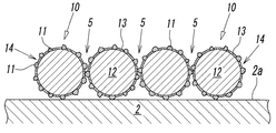
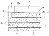
- the cross section of the core wire 12 that is, the cross section of the fixed abrasive wire 10 is substantially circular, as shown in FIG.
- a recess 5 is formed on the outer peripheral surface 2a of the base metal 2 between the fixed abrasive wires 10, 10 adjacent to each other in the direction of the rotation axis L.
- the concave portion 5 is formed of a valley-like space between the adjacent fixed abrasive wires 10 and 10, and is spirally formed from one end side to the other end side along the rotation axis L direction of the base metal 2 It is continuous.
- the above-mentioned recessed part 5 is a discharge groove which improves the dischargeability of the chips of the work W in the same manner as the chip pocket 14 between the adjacent abrasive grains 11 and 11 on the outer peripheral surface of the fixed abrasive wire 10 when grinding the work W. Act as.
- this fixed abrasive wire 10 is one in fixed abrasive wire 10 and 10 comrades which adjoin in the rotating shaft L direction.
- a state in which the tip portion (edge portion) of the abrasive grain 11 in the fixed abrasive wire 10 is in contact with the other fixed abrasive wire 10, that is, the average abrasive grain diameter of the abrasive grain 11 or the abrasive grain 11 from the metal plating layer 13 In a state in which a gap of about the amount of protrusion is formed, it is tightly wound on the outer peripheral surface 2a of the base metal 2 (see FIGS. 3 to 5).
- the fixed abrasive wire 10 has a first end and a second end at both ends in the longitudinal direction (longitudinal direction of the core wire 12). Then, as shown in FIG. 4, the first end 10 a of the fixed abrasive wire 10 is connected to one end side of the outer peripheral surface 2 a of the base metal 2 in the rotational axis L direction (that is, the shaft 4 in the outer peripheral surface 2 a is connected And the second end 10b of the wire 10 is positioned on the other end side of the outer peripheral surface 2a (opposite to the base in the rotational axis L direction) (as shown in FIG. 5). Fixed to the tip end side).
- the intermediate portion 10 c of the fixed abrasive wire 10 located between the first end 10 a and the second end 10 b is wound in a non-adherent state with respect to the outer peripheral surface 2 a of the base metal 2.
- the intermediate portion 10c can move relative to the outer peripheral surface 2a. That is, since the intermediate portion 10c of the wire 10 is not fixed to the base metal 2, it is slightly displaced in the rotation axis L direction or the circumferential direction on the outer peripheral surface 2a of the base metal 2 due to cutting resistance or the like. Or it can be slightly twisted around the central axis of the wire 10.
- reference numeral 16 denotes a fixing portion formed by fixing the second end 10b of the fixed abrasive wire 10 to the base metal 2 by the fixing means.
- the grinding wheel 1A is attached to the grinding device via the shaft 4 provided integrally with the base metal 2, and the grinding wheel 1A is Various grinding conditions relating to the feed speed, the number of rotations, the cut amount to the workpiece W, etc. are set. Then, after setting the grinding conditions, the grinding wheel 1A is rotated about the rotation axis L to feed the workpiece W toward the work W. Then, the workpiece W and the grinding portion 3 composed of the fixed abrasive wire 10 spirally wound around the workpiece facing surface of the base metal 2, that is, the outer peripheral surface 2a of the base metal 2 are in contact with each other.
- the workpiece W is gradually ground in the feed direction by the abrasive grains 11 exposed on the surface of the surface 10.
- the grinding process using this grinding wheel 1A is a dry process that does not use a grinding fluid, it is of course possible to work using a grinding fluid according to the processing conditions.
- Chips generated during grinding enter into the above-mentioned chip pockets 14 of the fixed abrasive wire 10 and are formed as discharge grooves for chips formed between the fixed abrasive wires 10, 10 adjacent in the direction of the rotation axis L.
- the chips that have entered the recess 5 are discharged to the outside by the rotation of the grinding wheel 1A.
- the fixed abrasive wire 10 is wound along the rotation axis L at substantially uniform intervals on the outer peripheral surface 2 a of the base metal 2, the recessed portion 5 extended in the circumferential direction of the base metal 2 Also, they are in a state of being disposed at substantially uniform intervals in the direction of the rotation axis L of the grinding wheel 1. Therefore, the concave portion 5 can be uniformly opposed to the workpiece W at any position of the grinding portion 3, whereby the chips can be discharged efficiently.
- this wire 10 is an intermediate portion located between the first end 10a and the second end 10b. 10c, the base metal 2 is wound so as to be able to move relative to the base metal 2 in a non-sticking state, and due to its grinding resistance, it slightly displaces or reciprocates or oscillates on the outer peripheral surface 2a of the base metal 2. It is possible to Therefore, for example, even if the workpiece W is made of a clogged material such as a soft material, the chips can be shaken off from the recess 5 and efficiently discharged.
- the process of manufacturing the said grinding stone 1A is demonstrated.
- the base metal 2 made of a metal material such as stainless steel, aluminum or super steel as described above and having the outer peripheral surface 2a around the rotation axis L and the core wire 12 made of a metal material such as a piano wire
- a long fixed-abrasive wire 10 is prepared, in which fine abrasive grains 11 made of or cBN are fixed.
- the fixed abrasive wire 10 is wound around the outer peripheral surface 2a of the base metal 2 to form a grinding portion 3 for grinding the work W and a recess 5 (discharge groove) for chip discharge. Move to the step.
- the fixed abrasive wire 10 is spirally tightened to the outer peripheral surface 2 a of the base metal 2 along the axis L direction. Tightly wound in the shape. Then, the fixed particle wire 10 is continuously and densely wound from the one end side to the other end side of the base metal 2 in the rotation axis L direction, so that one layer is fixed to the outer peripheral surface 2a of the base metal 2 A grinding portion 3 composed of abrasive wire 10 is formed. At the same time, a recess 5 (discharge groove) for chip discharge is formed between the fixed abrasive wires 10, 10 adjacent to each other in the rotational axis L direction.
- a winding method of the fixed abrasive wire 10 with respect to the base metal 2 it can carry out by using a predetermined
- both ends of the fixed abrasive wire 10 wound around the base metal 2 are cut or the like to form a first end and a second end at both ends in the longitudinal direction (core 12 direction), and the first end 10a Is fixed to one end side of the base metal 2 in the rotation axis L direction by an appropriate fixing method such as soldering, brazing, welding and the like. Further, in the same manner as the first end 10a, the second end 10b of the wire 10 is fixed to the other end side of the base metal 2 in the rotation axis L direction. As a result, the grinding wheel 1A in the present embodiment can be obtained.
- the fixed abrasive wire 10 fixed to the base metal 2 when the fixed abrasive wire 10 fixed to the base metal 2 is removed, for example, when a fixing means such as the above-described soldering is used, the fixed portion may be removed by an appropriate method such as laser heating. it can.
- the first end 10a of the fixed abrasive wire 10 is formed by cutting or the like. Is fixed to one end side of the base metal 2 and then the wire 10 is spirally wound from one end side to the other end side of the base metal 2 and then the second end 10b of the wire 10 is cut or the like It may be formed and fixed to the other end side of the base metal 2.
- the fixed abrasive wire 10 in which the abrasive grains 11 are fixed to the core wire 12 is spirally wound around the outer peripheral surface 2 a of the base metal 2 along the rotation axis L direction.
- the grinding portion 3 for grinding the workpiece W is formed, and at the same time, between the fixed abrasive wires 10 and 10 adjacent in the direction of the rotation axis L, for discharging chips.
- the recess 5 discharge groove
- the said base metal 2 is comprised so that it may be attached to a grinding apparatus via the shaft 4, it does not restrict to this, It is a base metal which has the attachment hole penetrated in thickness direction like a flat grindstone. It may be such that it is mounted on the spindle in the grinding apparatus via the mounting hole.
- the example which the said grinding stone 1 uses for surface grinding process is shown in FIG. 2, you may use not only this but for example, cylindrical grinding process or internal surface grinding process.
- the fixed abrasive wire 10 is fixed to the outer peripheral surface 2a of the base metal 2 at two points of the first end 10a and the second end 10b. It may be fixed to the base metal 2 at three or more locations including the central portion of the wire 10 wound around.
- the workpiece facing surface facing the workpiece W in this case is a substantially circular shape disposed on one side in the direction of the rotation axis L of the base metal 2 (the tip side located opposite to the shaft 4 in the axis L direction).
- the end face 2b is a point where the grinding portion 3 for grinding the work and the recess 5 for chip discharge are provided on the end face 2b.
- the grinding wheel 1B of the second embodiment is mainly used when performing lapping, and is provided on the end face 2b by pressing the end face 2b side of the base metal 2 rotating about the axis L against the work W
- the surface of the workpiece W is smoothed by the grinding portion 3.
- the remaining structure is substantially the same as that of the grinding wheel 1A according to the first embodiment, so the same reference numerals as those of the grinding wheel 1A according to the first embodiment are attached to the same main components.
- the description of the effects based on the parts and their constituent parts is omitted to avoid redundant description.
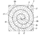
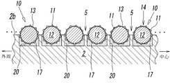
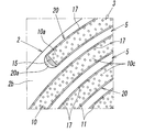
- the end face 2b of the base metal 2 has a uniformly flat surface, and the fixed abrasive wire 10 spirals around the rotation axis L on the end face 2b. It is fixed in a state of being wound in a shape.
- the grinding portion 3 is formed on the end face 2 b of the base metal 2, and the recess 5 for discharging chips between the fixed abrasive wires 10 and 10 adjacent in the radial direction of the base metal 2.
- the winding pitch in the radial direction of the base metal 2 and the number of turns thereof, the number of wires 10, etc. are arbitrary, but in the present embodiment, one fixed abrasive wire 10 is used. It is closely wound in a spiral manner from the vicinity of the outer peripheral edge to the substantially central position on the end face 2b.
- the first end 10a of the fixed abrasive wire 10 is fixed to the outer peripheral edge side of the end face 2b of the base metal 2,
- the second end 10b of the fixed abrasive wire 10 is fixed at a substantially central position of the end face 2b.
- the intermediate portion 10c located between the first end 10a and the second end 10b has a predetermined distance from the end face 2b along the longitudinal direction of the fixed abrasive wire 10. It is fixed intermittently. Therefore, in the intermediate portion 10c, the fixed portion 17 fixed to the end surface 2b of the base metal 2 and the non-fixed portion not fixed to the end surface 2b of the base metal 2 are alternately arranged along the longitudinal direction. (See FIGS. 8 and 9). As a result, the non-sticking portion is configured to be displaced or rocked on the end face 2 b of the base metal 2 due to cutting resistance or the like in the grinding process of the workpiece W.
- the fixing means of the fixed abrasive wire 10 to the base metal 2 is performed by soldering, brazing, welding or the like as in the first embodiment, and in the present embodiment, as shown by reference numeral 17 in FIG.
- the fixed abrasive wire 10 is point-joined by spot welding such as resistance welding, laser welding, or arc welding.
- spot welding such as resistance welding, laser welding, or arc welding.
- each fixed part 17 of the fixed abrasive wire 10 is located in the radial direction inner side of the base metal 2, you may be located in the radial direction outer side. Further, 15 in FIG.
- FIG. 8 is a fixed portion formed by fixing the first end 10a of the fixed abrasive wire 10 to the end face 2b of the base metal 2 at the position near the outer peripheral edge of the end face 2b by the fixing means.
- 16 in FIG. 9 is a fixing portion formed by fixing the second end 10b to the end face 2b at the approximate center position of the end face 2b by the fixing means.
- the base metal 2 and the fixed abrasive wire 10 are prepared, and the fixed abrasive wire 10 is placed on the end face 2b of the base 2 and the rotation axis L It fixes with respect to this end surface 2b, winding tightly around spirally.
- the fixed abrasive wire 10 is wound from the outer peripheral edge side of the base metal 2 toward the center side a plurality of times.
- the winding start end side (first end portion 10a side) of the fixed abrasive wire 10 is fixed to the base metal by fixing means such as spot welding at a position near the outer peripheral edge of the end face 2b.
- the fixed abrasive wire 10 is spirally wound toward the center of the end face 2b, the fixed abrasive wire 10 is fixed to the base metal 2 at a predetermined interval along the length direction of the fixed abrasive wire 10. . This is sequentially repeated, and finally, the winding end side (second end portion 2b side) of the fixed abrasive wire 10 is fixed to the base metal 2 at a substantially central position (near the rotation axis L) of the end surface 2b of the base metal 2. Do. Then, in the fixed abrasive wire 10, excess portions on the winding start end side and the winding end side are cut or the like.
- the fixed abrasive wire 10 is spirally fixed to the end face 2 b of the base metal 2, and between the fixed abrasive wires 10, 10 adjacent in the radial direction of the base metal 2.
- a grinding wheel 1B in which the recess 5 for chip discharge is formed.
- both ends of the fixed abrasive wire 10 are cut to form the first end 10a and the second end 10b in advance, and they are used as a base metal as described above. It is also possible to fix to the end face 2b while winding it on the end face 2b.
- the fixed abrasive wire 10 is wound from the outer peripheral edge side of the base metal toward the center, but it is of course possible to wind from the central side toward the outer peripheral edge side. It is also possible to weld the fixed abrasive wire 10 sequentially from the outer side of the base metal 2 in the radial direction.
- the grinding wheel 1C according to the third embodiment differs from the grinding wheel 1B according to the second embodiment in that the end face 2b forming a workpiece-facing surface facing the workpiece W is recessed substantially spirally around the rotation axis L.
- a guide groove 20 is provided, and the fixed abrasive wire 10 is disposed in the guide groove 20 in a spirally wound state along the guide groove 20, and the guide groove 20 is in this state. It is a point fixed to the base metal inside.
- the spiral guide groove 20 continues without break from the vicinity of the outer peripheral edge to the central portion of the end face 2 b of the base metal 2.
- the guide groove 20 has a substantially rectangular cross-sectional shape, and the groove width is formed to be slightly larger than the diameter of the fixed abrasive wire 10, and the groove depth Is shallower than the diameter of the fixed abrasive wire 10. Therefore, when the fixed abrasive wire 10 is accommodated in the groove 20 along the longitudinal direction of the guide groove 20, the substantially arc-shaped surface of the fixed abrasive wire 10 is made of the above-mentioned base metal 2 as shown in FIG.
- the workpiece W can be ground by the fixed abrasive wire 10 protruding from the end face 2 b and protruding therefrom.
- the recess 5 for chip discharge is between the fixed abrasive wires 10, 10 adjacent to each other in the radial direction of the base metal 2. It is formed. Further, the winding pitch of the fixed abrasive wire 10, 10 for determining the width of the recess 5 substantially corresponds to the radial pitch of the guide groove 20 adjacent in the radial direction of the base metal 2; In the embodiment, the winding pitch of the guide groove 20 is such that the abrasive grains 11 of the adjacent fixed abrasive wires 10, 10 do not contact each other with the fixed abrasive wire 10 accommodated in the guide groove 20. It is set to be separated to such an extent that
- a resin adhesive is used as a fixing means of the fixed abrasive wire 10. Then, with the adhesive, as shown in FIG. 12 or FIG. 13, the first end 10 a of the fixed abrasive wire 10 is a groove end at one end side (the outermost side) in the length direction in the guide groove 20. The second end 10b is fixed at the position 20a, and is fixed at the position of the groove end 20b on the other end side (central side) of the guide groove 20 in the longitudinal direction.
- the middle portion 10 c of the fixed abrasive wire is fixed to the base metal 2 intermittently along the length direction of the fixed abrasive wire 10 in the guide groove 20.
- the fixed portion 15-17 of the abrasive wire 10 may be configured to be slightly displaced on the end face 2b while being fixed to the end face 2b. Further, in the example shown in FIG. 11, the fixed abrasive wire 10 is fixed to the base metal 2 in a non-contact state at the groove bottom of the guide groove 20, but the guide groove is in contact with the groove bottom. It may be fixed within 20.
- a process of manufacturing the grinding wheel 1C shown in the third embodiment will be described.
- the end face 2b of the base metal 2 is swirled around the rotation axis L of the base metal 2.
- Shaped guide grooves 20 are formed.
- the step of forming the guide groove 20 is performed, for example, by a laser processing machine or the like, whereby a spiral groove having an appropriate groove width and groove depth is formed at a predetermined winding pitch.
- a resin-based adhesive is filled in the groove end 20a at one end located on the outermost side and the groove end 20b at the other end located on the innermost side in the guide groove 20, and Between the groove end portions 20a and 20b, adhesive is intermittently filled at predetermined intervals along the longitudinal direction of the guide groove 20. By doing so, an adhesive layer (portion of the fixing portion 15-17) is formed on the portion of the guide groove 20 filled with the adhesive. Then, the process proceeds to the fixing step described below, in which the fixed abrasive wire 10 is moved along the longitudinal direction of the guide groove 20 before the adhesive layer is cured. Place inside.
- the fixed abrasive wire 10 which is formed to have a length corresponding to the length of the guide groove and has the first end 10a and the second end 10b in advance is used, of course, As described in the manufacturing process of the grinding wheel 1B according to the second embodiment, after fixing the long fixed abrasive wire 10 to the base metal 2 (in the guide groove 20), both ends of the fixed abrasive wire 10 are cut The first end 10a and the second end 10b may be formed.
- the fixed abrasive wire 10 is spirally wound along the longitudinal direction of the guide groove 20, and as shown in FIG. 13, the second end of the fixed abrasive wire 10
- the portion 10 b is disposed so as to substantially coincide with the other groove end 20 b of the guide groove 20.
- the fixed abrasive wire 10 is spirally fixed to the end face 2 b of the base metal 2, and between the fixed abrasive wires 10, 10 adjacent in the radial direction of the base metal 2.
- the guide groove 20 is formed by a laser processing machine, but may be formed by cutting with, for example, a cutting blade of a cutting tool.
- a part of the fixed abrasive wire 10 may be accommodated in the guide groove 20, and a part of the outer peripheral surface of the fixed abrasive wire 10 may be protruded to the outside. If possible, for example, it may have a substantially circular cross section or a substantially V-shaped cross section.
Abstract
[Problem] To provide a grinding stone with excellent ability to discharge swarf and with which grinding efficiency can be improved, and a production method for such a grinding stone. [Solution] The grinding stone has a metal base 2 with a workpiece-facing surface that faces a workpiece W and a fixed abrasive grain wire 10 made by fixing many abrasive grains 11 on a core wire 12. Fixing the fixed abrasive grain wire 10 on the workpiece-facing surface of the metal base 2 forms a grinding section 3 for workpiece grinding on the workpiece-facing surface and forms discharging grooves for discharging swarf that are constituted from the crevices 5 between adjacent fixed abrasive grain wires 10 and 10.
Description
本発明は、金属材料やセラミックス材料等から成るワークの研削に用いられる研削砥石及びその製造方法に関するものである。
The present invention relates to a grinding wheel used for grinding a workpiece made of a metal material, a ceramic material or the like, and a method of manufacturing the same.
従来から、金属材料やセラミックス材料等から成るワークを研削する研削砥石としては、例えば、ワークに対向するワーク対向面を有する台金と、該ワーク対向面にダイヤモンドやcBN等の砥粒が適宜のボンド材で保持された砥粒層すなわち研削層とを有するものが知られている(特許文献1参照)。そして、このような研削砥石を用いてワークを研削する際には、該研削砥石を適宜の研削装置に取り付け、台金をその軸周りに高速回転させながらワークに向けて送りを与えて、該台金のワーク対向面上に配された研削層をワークに接触させる。そうすることで、研削層の表面に露出した砥粒が切れ刃となって、該ワークが研削される。
Conventionally, as a grinding wheel for grinding a workpiece made of a metal material, a ceramic material or the like, for example, a base metal having a workpiece facing surface facing the workpiece, and abrasive grains such as diamond or cBN on the workpiece facing surface are suitable. It is known to have an abrasive layer or grinding layer held by a bonding material (see Patent Document 1). Then, when grinding a work using such a grinding wheel, the grinding wheel is attached to a suitable grinding device, and the base metal is fed at a high speed while rotating around its axis to feed it toward the work, The grinding layer disposed on the workpiece facing surface of the base metal is brought into contact with the workpiece. By doing so, the abrasive grains exposed on the surface of the grinding layer become cutting edges, and the work is ground.
ところで、この種の研削砥石においては、ワークの研削の際に生ずる切屑が、砥粒間のチップポケット内に堆積することで目詰まりが発生してしまい、その結果、研削効率の低下を招く虞がある。そのため、このような研削砥石においては、上記研削層に、切屑の排出性を高める為の切屑排出用の排出溝を設け、該排出溝を通じて上記切屑を外部に排出させることが好ましい。
なお、本発明に関連する先行技術文献として、例えば、特許文献2のようなものが挙げられる。 By the way, in this type of grinding wheel, chips generated during grinding of a workpiece are accumulated in chip pockets between abrasive grains, which may cause clogging, and as a result, the grinding efficiency may be reduced. There is. Therefore, in such a grinding wheel, it is preferable that a discharge groove for chip discharge is provided in the grinding layer to enhance chip dischargeability, and the chips are discharged to the outside through the discharge groove.
In addition, as a prior art document relevant to this invention, a thing likepatent document 2 is mentioned, for example.
なお、本発明に関連する先行技術文献として、例えば、特許文献2のようなものが挙げられる。 By the way, in this type of grinding wheel, chips generated during grinding of a workpiece are accumulated in chip pockets between abrasive grains, which may cause clogging, and as a result, the grinding efficiency may be reduced. There is. Therefore, in such a grinding wheel, it is preferable that a discharge groove for chip discharge is provided in the grinding layer to enhance chip dischargeability, and the chips are discharged to the outside through the discharge groove.
In addition, as a prior art document relevant to this invention, a thing like
そこで、本発明の技術的課題は、切屑の排出性に優れ、研削効率の向上を図ることができる研削砥石及びそのような研削砥石の製造方法を提供することにある。
Then, the technical subject of this invention is excellent in the discharge | emission property of chips, and is providing the grinding wheel which can aim at the improvement of grinding efficiency, and the manufacturing method of such a grinding wheel.
上記課題を解決するため、本発明によれば、ワークに対向させるためのワーク対向面を有する台金と、芯線に多数の砥粒が固着されて成る固定砥粒ワイヤーとを有し、上記固定砥粒ワイヤーが、台金における上記ワーク対向面に隣り合って延びるように固定されることで、該ワーク対向面上に、ワーク研削用の研削部が形成されていると共に、隣り合う固定砥粒ワイヤー間の凹部から成る切屑排出用の排出溝が形成されていることを特徴とする研削砥石が提供される。
In order to solve the above problems, according to the present invention, it has a base metal having a workpiece facing surface for facing a workpiece, and a fixed abrasive wire in which a large number of abrasive grains are fixed to a core wire, The abrasive wire is fixed so as to extend adjacent to the workpiece facing surface of the base metal, whereby a grinding portion for workpiece grinding is formed on the workpiece facing surface, and adjacent fixed abrasive particles are formed. There is provided a grinding wheel characterized in that a discharge groove for chip discharge, which is a recess between wires, is formed.
このとき、好ましくは、上記台金のワーク対向面が、該台金の回転軸周りの外周面から成っており、上記固定砥粒ワイヤーが、台金の外周面に上記回転軸方向に沿って螺旋状に巻かれた状態で該台金に固定されていて、それにより、該台金の外周面上に上記研削部が形成されていると共に、上記回転軸方向に隣り合う固定砥粒ワイヤー間の凹部により上記排出溝が形成されている。
そして、より好ましくは、上記固定砥粒ワイヤーは、その長手方向の両端に第1端と第2端をそれぞれ有していて、その第1端部が台金の回転軸方向の一端側に固着され、その第2端部が該台金の回転軸方向の他端側に固着されていると共に、これら第1端部と第2端部との間に位置する中間部が、上記台金の外周面に対して、非固着状態で上記回転軸方向に相対動可能に巻かれている。 At this time, preferably, the workpiece-facing surface of the base metal is formed of an outer peripheral surface around the rotation axis of the base metal, and the fixed abrasive wire is formed on the outer peripheral surface of the base metal along the rotational axis direction. Between the fixed abrasive wire which is fixed to the base metal in a spirally wound state, whereby the grinding portion is formed on the outer peripheral surface of the base metal and adjacent to the rotation axis direction. The discharge groove is formed by the concave portion of
And, more preferably, the fixed abrasive wire has a first end and a second end at both ends in the longitudinal direction, and the first end is fixed to one end side of the base metal in the rotation axis direction The second end is fixed to the other end side of the base metal in the direction of the rotation axis of the base metal, and the intermediate part located between the first end and the second end is the base metal. Relative to the outer peripheral surface, it is wound so as to be capable of relative movement in the direction of the rotation axis in a non-sticking state.
また、上記本発明に係る研削砥石においては、上記台金のワーク対向面が、該台金の回転軸方向における一端側の端面から成っており、上記固定砥粒ワイヤーが、台金の端面上において、上記回転軸周りに渦巻き状に巻かれた状態で該台金に固定されていて、それにより、該台金の端面上に上記研削部が形成されていると共に、該台金の径方向で隣り合う固定砥粒ワイヤー間の凹部によって上記排出溝が形成されていてもよい。
In the grinding wheel according to the present invention, the work-facing surface of the base metal is an end face on one end side in the rotation axis direction of the base metal, and the fixed abrasive wire is on the end face of the base metal. Wherein the grinding portion is formed on the end face of the base metal, and the radial direction of the base metal is fixed to the base metal in a spirally wound state around the rotation axis. The said discharge groove may be formed of the recessed part between the fixed abrasive wires which adjoin each other.
このとき、好ましくは、上記固定砥粒ワイヤーは、その長手方向の両端に第1端と第2端をそれぞれ有していて、上記第1端部が、台金の端面における径方向一方側で固着され、第2端部が該台金の径方向他方側で固着されていると共に、これら第1端部と第2端部との間に位置する中間部が、該台金の端面に対し、固定砥粒ワイヤーの長手方向に沿って断続的に固着されている。
At this time, preferably, the fixed abrasive wire has a first end and a second end at both ends in the longitudinal direction, and the first end is on one side in the radial direction of the end face of the base metal. An intermediate portion which is fixed, the second end is fixed on the other side in the radial direction of the base metal, and an intermediate portion located between the first end and the second end is opposed to the end face of the base metal. , And fixed intermittently along the longitudinal direction of the fixed abrasive wire.
また、上記台金の端面には、渦巻き状に凹設されたガイド溝が刻設されており、上記固定砥粒ワイヤーが、このガイド溝の長さ方向に沿って該ガイド溝内に配設された状態で、該台金に固定されていてもよい。
Further, a spirally recessed guide groove is engraved on the end face of the base metal, and the fixed abrasive wire is disposed in the guide groove along the longitudinal direction of the guide groove. It may be fixed to the base metal in a fixed state.
さらに、本発明によれば、ワークに対向させるためのワーク対向面を有する台金の該ワーク対向面上に、ワーク研削用の研削部と切屑排出用の排出溝とが形成された研削砥石の製造方法であって、上記台金の回転軸周りの外周面を上記ワーク対向面とし、芯線に砥粒が固着されて成る固定砥粒ワイヤーを、該台金の外周面に、その回転軸方向の一端側から他端側に向けて螺旋状に巻くことによって、該外周面上に、上記研削部を形成すると共に、上記回転軸方向に隣り合う固定砥粒ワイヤー間の凹部により上記排出溝を形成するステップと、固定砥粒ワイヤーの長手方向における第1端部及び第2端部を該台金に固着するステップとを含むことを特徴とする研削砥石の製造方法が提供される。
Furthermore, according to the present invention, a grinding wheel in which a grinding portion for grinding a workpiece and a discharge groove for discharging chips are formed on the workpiece-facing surface of a base metal having a workpiece-facing surface for facing a workpiece. In the manufacturing method, a fixed abrasive wire having an outer peripheral surface around the rotation axis of the base metal as the work-facing surface, and a fixed abrasive wire having abrasive grains fixed to the core wire is formed on the outer peripheral surface of the base metal in the rotational axis direction. The grinding portion is formed on the outer peripheral surface by spirally winding from one end side to the other end side, and the discharge groove is formed by the concave portion between the fixed abrasive wires adjacent in the rotation axis direction. A method of manufacturing a grinding wheel is provided comprising the steps of forming and securing the first end and the second end in the longitudinal direction of the fixed abrasive wire to the base metal.
また、本発明によれば、ワークに対向するワーク対向面を有する台金の該ワーク対向面上に、ワーク研削用の研削部と切屑排出用の排出溝とが形成された研削砥石の製造方法であって、上記台金の回転軸方向の一端側の端面を上記ワーク対向面とし、芯線に砥粒が固着されて成る固定砥粒ワイヤーを、該台金の端面上で、その回転軸周りに渦巻き状に巻くことによって、該端面上に上記研削部を形成すると共に、該端面の径方向に隣り合う固定砥粒ワイヤー間の凹部により上記排出溝を形成するステップと、固定砥粒ワイヤーの長手方向における第1端部及び第2端部、並びに該固定砥粒ワイヤーの第1端部と第2端部との間に位置する中間部を、台金に固着するステップとを含むことを特徴とする研削砥石の製造方法が提供される。
Further, according to the present invention, there is provided a method of manufacturing a grinding stone in which a grinding portion for grinding a workpiece and a discharge groove for discharging chips are formed on the workpiece-facing surface of a base metal having a workpiece-facing surface facing a workpiece. The fixed abrasive wire having an end face on one end side in the rotation axis direction of the base metal as the work-facing surface and the abrasive grains fixed to the core wire is placed on the end face of the base metal around its rotation axis. Forming the grinding portion on the end face by spirally winding, and forming the discharge groove by the recess between the fixed abrasive wires adjacent to each other in the radial direction of the end face; Securing the first end and the second end in the longitudinal direction and an intermediate portion located between the first end and the second end of the fixed abrasive wire to the base metal. A method of manufacturing a grinding wheel characterized by the present invention is provided.
このとき、上記台金の端面に、上記回転軸周りに渦巻き状に凹設されたガイド溝を刻設するステップと、上記固定砥粒ワイヤーを、上記ガイド溝の長さ方向に沿って該ガイド溝内に配置するステップとを含んでいてもよい。
At this time, in the end face of the base metal, a step of engrave a guide groove recessed in a spiral manner around the rotation axis, and the fixed abrasive wire along the length direction of the guide groove. And disposing in the groove.
以上に記した本発明によれば、台金におけるワークに対向するワーク対向面に、固定砥粒ワイヤーを固定することにより、該台金のワーク対向面上に、ワーク研削用の研削部と切屑排出用の排出溝とが同時に形成される。したがって、切屑の排出性に優れ、研削効率の向上も図ることが可能な研削砥石及び該研削砥石の製造方法を提供することができる。
According to the present invention described above, the fixed abrasive wire is fixed to the workpiece facing surface facing the workpiece in the base metal, whereby the grinding portion and chips for grinding the workpiece on the workpiece facing surface of the base metal A discharge groove for discharge is simultaneously formed. Therefore, it is possible to provide a grinding wheel which is excellent in chip dischargeability and can improve the grinding efficiency, and a method of manufacturing the grinding wheel.
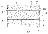
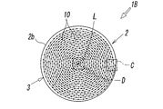
図1-図5は、本発明に係る研削砥石の第1の実施形態を示している。この研削砥石1Aは、金属材料やセラミックス等のワークWを研削する為のもので、ワークWに対向するワーク対向面を有する台金2と、該ワーク対向面上に設けられたワーク研削用の研削部3とを有している。この研削砥石1AによってワークWを研削する際には、図2に示すように、該台金2を図示しない適宜の研削装置に取り付け、台金2に対してその回転軸L周りに回転させた状態で送りを与え、台金2のワーク研削面(後述の台金2の外周面2a)に設けられた研削部3をワークWに接触させる。
1 to 5 show a first embodiment of a grinding wheel according to the present invention. The grinding wheel 1A is for grinding a workpiece W such as a metal material or a ceramic, and the base metal 2 having a workpiece facing surface facing the workpiece W, and the workpiece grinding surface provided on the workpiece facing surface And a grinding unit 3. When grinding the work W with this grinding wheel 1A, as shown in FIG. 2, the base metal 2 was attached to a suitable grinding device (not shown) and was rotated about its rotation axis L with respect to the base metal 2 Feeding is performed in a state, and the grinding portion 3 provided on the work grinding surface of the base metal 2 (the outer peripheral surface 2a of the base metal 2 described later) is brought into contact with the work W.
上記台金2は、例えばステンレス鋼、アルミニウム、超鋼等の金属によって円柱状ないし円筒状に形成され断面円形を成しており、本実施形態においては、上記ワーク対向面が、台金2の回転軸L周りの円形外周面2aから成っている。また、この台金2には、図1又は図2に示すように、それよりも小径の丸棒状に形成されたシャフト4が一体的に設けられている。このシャフト4は研削装置にクランプされる部分である。上記台金2は、シャフト4を介して上記研削装置に取り付けられることで、該研削装置の駆動力によって軸L周りに回転すると同時に、3軸方向に移動することができるようになっている。なお、台金2及びシャフト4の外径及び回転軸L方向長さは、研削するワークの寸法等に合わせて任意に設定することが可能である。
The base metal 2 is formed in a cylindrical or cylindrical shape and formed in a circular cross-section, for example, by a metal such as stainless steel, aluminum, super steel, etc. In the present embodiment, the work opposing surface is the base metal. It comprises a circular outer peripheral surface 2a around the rotation axis L. Further, as shown in FIG. 1 or 2, the base metal 2 is integrally provided with a shaft 4 formed in a round rod shape smaller in diameter than that. The shaft 4 is a portion to be clamped by the grinding device. The base metal 2 is attached to the grinding apparatus through the shaft 4 so that it can rotate in the three axial directions while rotating about the axis L by the driving force of the grinding apparatus. The outer diameters of the base metal 2 and the shaft 4 and the lengths in the direction of the rotation axis L can be arbitrarily set in accordance with the dimensions of the workpiece to be ground.
次いで、本発明の特徴部分である研削部3の具体的構成について説明する。図1又は図2に示すように、この研削部3は、後述する可撓性を有する固定砥粒ワイヤー10が、上記台金2の外周面2a上に、上記回転軸L方向に沿って螺旋状に巻かれた状態で台金2に固定されることにより形成されている。そして、固定砥粒ワイヤー10の表面に露出した砥粒11が切刃となり、上記ワークWを研削するようになっている。
Next, a specific configuration of the grinding unit 3 which is a feature of the present invention will be described. As shown in FIG. 1 or FIG. 2, in the grinding portion 3, the fixed abrasive wire 10 having flexibility described later spirals along the direction of the rotation axis L on the outer peripheral surface 2 a of the base metal 2. It is formed by being fixed to the base metal 2 in a wound state. And the abrasive grain 11 exposed to the surface of the fixed abrasive wire 10 becomes a cutting blade, and the said workpiece | work W is ground.
図3に示すように、上記研削砥石1Aに用いられる固定砥粒ワイヤー10としては、ピアノ線等の金属製で可撓性を有する芯線12に、ダイヤモンドや立方晶窒化ホウ素(cBN)等の微細な上記砥粒11が単層状態(単粒状態)で固着されて成るものが好適に用いられる。このとき、芯線12への砥粒11の固着は適宜の固着方法により行われるが、本実施形態のように、上記砥粒11が芯線12上に単層状態で固着されている場合には、該砥粒11の自生発刃効果が生じないことから、砥粒11が脱粒してしまうと脱粒部分における切れ味が鈍くなってしまう。
As shown in FIG. 3, as the fixed abrasive wire 10 used for the grinding wheel 1A, fine wires such as diamond or cubic boron nitride (cBN) can be used as the core wire 12 made of metal such as piano wire and having flexibility. Preferably, the abrasive grains 11 are fixed in a single layer state (single particle state). At this time, fixing of the abrasive grains 11 to the core wire 12 is performed by an appropriate fixing method, but when the abrasive grains 11 are fixed in a single layer state on the core wire 12 as in the present embodiment, Since the spontaneous growth effect of the abrasive grains 11 does not occur, when the abrasive grains 11 are disintegrated, the sharpness in the disaggregated portion becomes dull.
そこで、本実施形態では、上記砥粒11を、ニッケル、銅等のボンド材を用いた電着による金属めっき層13で固着することにより、該砥粒11の芯線12への保持力が高められている。そのため、芯線12からの砥粒11の脱粒を可及的に抑えて固定砥粒ワイヤー10すなわち研削部3の劣化を抑制することができ、研削砥石1Aや固定砥粒ワイヤー10の交換頻度を低減することができる。
Therefore, in the present embodiment, by fixing the abrasive grains 11 with the metal plating layer 13 by electrodeposition using a bonding material such as nickel and copper, the retention strength of the abrasive grains 11 to the core wire 12 is enhanced. ing. Therefore, it is possible to suppress the dropout of the abrasive grains 11 from the core wire 12 as much as possible and to suppress the deterioration of the fixed abrasive wire 10, that is, the grinding portion 3 and reduce the replacement frequency of the grinding wheel 1A and the fixed abrasive wire 10 can do.
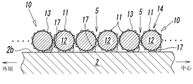
本実施形態において、上記研削部3は、1本の上記固定砥粒ワイヤー10を、台金2の外周面2aに対し、回転軸L方向に沿うように、該台金2の一端側から他端側に向けて連続して一重に巻くことにより構成されている。このように、台金2に対して固定砥粒ワイヤー10が一重の螺旋状に巻かれると、芯線12の断面すなわち固定砥粒ワイヤー10の断面が略円形であるため、図3-図5に示すように、台金2の外周面2a上には、上記回転軸L方向に互いに隣接する固定砥粒ワイヤー10,10間に凹部5が形成される。
In the present embodiment, the grinding unit 3 is arranged so that one fixed abrasive wire 10 extends from the one end side of the base metal 2 along the rotation axis L direction with respect to the outer peripheral surface 2 a of the base metal 2. It is configured by continuously winding in a single layer toward the end side. Thus, when the fixed abrasive wire 10 is wound in a single spiral shape with respect to the base metal 2, the cross section of the core wire 12, that is, the cross section of the fixed abrasive wire 10 is substantially circular, as shown in FIG. As shown, a recess 5 is formed on the outer peripheral surface 2a of the base metal 2 between the fixed abrasive wires 10, 10 adjacent to each other in the direction of the rotation axis L.
この凹部5は、隣り合う固定砥粒ワイヤー10,10間の谷状空間から成るものであって、台金2の上記回転軸L方向に沿って一端側から他端側に亘って螺旋状に連続している。上記凹部5は、ワークWの研削加工の際に、固定砥粒ワイヤー10の外周面における隣接する砥粒11,11間のチップポケット14と同様に、ワークWの切屑の排出性を高める排出溝として機能する。
The concave portion 5 is formed of a valley-like space between the adjacent fixed abrasive wires 10 and 10, and is spirally formed from one end side to the other end side along the rotation axis L direction of the base metal 2 It is continuous. The above-mentioned recessed part 5 is a discharge groove which improves the dischargeability of the chips of the work W in the same manner as the chip pocket 14 between the adjacent abrasive grains 11 and 11 on the outer peripheral surface of the fixed abrasive wire 10 when grinding the work W. Act as.
なお、上記固定砥粒ワイヤー10の巻回ピッチは任意であるが、本実施形態では、該固定砥粒ワイヤー10は、回転軸L方向に隣り合う固定砥粒ワイヤー10,10同士において、一方の固定砥粒ワイヤー10における砥粒11の先端部(刃先部)が、他方の固定砥粒ワイヤー10に接した状態すなわち、凡そ砥粒11の平均砥粒径ないし金属めっき層13からの砥粒11の突き出し量程度の隙間が形成された状態で、台金2の外周面2a上に密巻きされている(図3-図5参照)。
In addition, although the winding pitch of the said fixed abrasive wire 10 is arbitrary, in this embodiment, this fixed abrasive wire 10 is one in fixed abrasive wire 10 and 10 comrades which adjoin in the rotating shaft L direction. A state in which the tip portion (edge portion) of the abrasive grain 11 in the fixed abrasive wire 10 is in contact with the other fixed abrasive wire 10, that is, the average abrasive grain diameter of the abrasive grain 11 or the abrasive grain 11 from the metal plating layer 13 In a state in which a gap of about the amount of protrusion is formed, it is tightly wound on the outer peripheral surface 2a of the base metal 2 (see FIGS. 3 to 5).
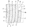
上記固定砥粒ワイヤー10は、その長手方向(芯線12の長手方向)の両端に第1端と第2端とをそれぞれ有している。そして、図4に示すように、該固定砥粒ワイヤー10の第1端部10aが、台金2の外周面2aにおける回転軸L方向の一端側(すなわち、外周面2aにおけるシャフト4が連結された基端部)に固着され、図5に示すように、該ワイヤー10の第2端部10bが、上記外周面2aの他端側(回転軸L方向において上記基端部と反対側に位置する先端部側)に固着されている。
The fixed abrasive wire 10 has a first end and a second end at both ends in the longitudinal direction (longitudinal direction of the core wire 12). Then, as shown in FIG. 4, the first end 10 a of the fixed abrasive wire 10 is connected to one end side of the outer peripheral surface 2 a of the base metal 2 in the rotational axis L direction (that is, the shaft 4 in the outer peripheral surface 2 a is connected And the second end 10b of the wire 10 is positioned on the other end side of the outer peripheral surface 2a (opposite to the base in the rotational axis L direction) (as shown in FIG. 5). Fixed to the tip end side).
その一方で、これら第1端部10aと第2端部10bとの間に位置する固定砥粒ワイヤー10の中間部10cは、上記台金2の外周面2aに対して非固着状態で巻かれており、その結果、この中間部10cは、上記外周面2aに対して相対動可能となっている。すなわち、このワイヤー10の中間部10cは、台金2に対して固定されていないため、切削抵抗等により、上記台金2の外周面2a上において、回転軸L方向や周方向に微少に変位したり、当該ワイヤー10の中心軸回りに微少に捩れたりすることが可能となっている。
On the other hand, the intermediate portion 10 c of the fixed abrasive wire 10 located between the first end 10 a and the second end 10 b is wound in a non-adherent state with respect to the outer peripheral surface 2 a of the base metal 2. As a result, the intermediate portion 10c can move relative to the outer peripheral surface 2a. That is, since the intermediate portion 10c of the wire 10 is not fixed to the base metal 2, it is slightly displaced in the rotation axis L direction or the circumferential direction on the outer peripheral surface 2a of the base metal 2 due to cutting resistance or the like. Or it can be slightly twisted around the central axis of the wire 10.
なお、図4における15は、台金2に対して、上記固定砥粒ワイヤー10の第1端部10aをはんだ付け、ロウ付け、或いは、溶接等の固着手段で固定して成る固着部であり、また、図5において16は、上記固定砥粒ワイヤー10の第2端部10bを、同じく台金2に対して上記固着手段で固定して成る固着部である。
4 in FIG. 4 is a fixed portion formed by fixing the first end 10a of the fixed abrasive wire 10 to the base metal 2 by means of soldering, brazing or welding. Further, in FIG. 5, reference numeral 16 denotes a fixing portion formed by fixing the second end 10b of the fixed abrasive wire 10 to the base metal 2 by the fixing means.
上記研削砥石1Aを用いてワークWを研削する場合、上述したように、研削砥石1Aを、台金2と一体に設けられたシャフト4を介して研削装置に取り付け、研削装置によって研削砥石1Aの送り速度や回転数、ワークWに対する切り込み量等に関する各種研削条件を設定する。そして、研削条件設定後、研削砥石1Aを上記回転軸L周りに回転させた状態でワークWに向けて送りを与える。そうすると、ワークWと、台金2のワーク対向面、即ち台金2の外周面2aに螺旋状に巻き付けられた固定砥粒ワイヤー10から成る研削部3とが接触して、該固定砥粒ワイヤー10の表面に露出した砥粒11により該ワークWが上記送り方向に徐々に研削されていく。このとき、この研削砥石1Aによる研削加工は、研削液を使用しないドライ加工であることが望ましいが、加工条件に応じて研削液を使用して加工することも勿論可能である。
When the workpiece W is ground using the grinding wheel 1A, as described above, the grinding wheel 1A is attached to the grinding device via the shaft 4 provided integrally with the base metal 2, and the grinding wheel 1A is Various grinding conditions relating to the feed speed, the number of rotations, the cut amount to the workpiece W, etc. are set. Then, after setting the grinding conditions, the grinding wheel 1A is rotated about the rotation axis L to feed the workpiece W toward the work W. Then, the workpiece W and the grinding portion 3 composed of the fixed abrasive wire 10 spirally wound around the workpiece facing surface of the base metal 2, that is, the outer peripheral surface 2a of the base metal 2 are in contact with each other. The workpiece W is gradually ground in the feed direction by the abrasive grains 11 exposed on the surface of the surface 10. At this time, although it is desirable that the grinding process using this grinding wheel 1A is a dry process that does not use a grinding fluid, it is of course possible to work using a grinding fluid according to the processing conditions.
研削の際に発生した切屑は、固定砥粒ワイヤー10の上記チップポケット14内に入り込むと共に、回転軸L方向に隣り合う該固定砥粒ワイヤー10,10間に形成された、切屑の排出溝としての凹部5にも入り込んでいく。そして、この凹部5に入り込んだ切屑は、研削砥石1Aの回転によって外部に排出されていく。このとき、上記固定砥粒ワイヤー10が回転軸Lに沿って台金2の外周面2aにほぼ均一な間隔で巻かれていることから、台金2の周方向に延設された上記凹部5も、研削砥石1の回転軸L方向にほぼ均一な間隔で配置された状態となっている。そのため、研削部3のどの位置においても、ワークWに対して、上記凹部5を均一に対峙させることができ、それにより、切屑の排出を効率よく行うことができる。
Chips generated during grinding enter into the above-mentioned chip pockets 14 of the fixed abrasive wire 10 and are formed as discharge grooves for chips formed between the fixed abrasive wires 10, 10 adjacent in the direction of the rotation axis L. Into the recess 5 of the The chips that have entered the recess 5 are discharged to the outside by the rotation of the grinding wheel 1A. At this time, since the fixed abrasive wire 10 is wound along the rotation axis L at substantially uniform intervals on the outer peripheral surface 2 a of the base metal 2, the recessed portion 5 extended in the circumferential direction of the base metal 2 Also, they are in a state of being disposed at substantially uniform intervals in the direction of the rotation axis L of the grinding wheel 1. Therefore, the concave portion 5 can be uniformly opposed to the workpiece W at any position of the grinding portion 3, whereby the chips can be discharged efficiently.
また、ワークW研削時、固定砥粒ワイヤー10には研削抵抗が生ずるが、上述のように、このワイヤー10は、その第1端部10aと第2端部10bとの間に位置する中間部10cにおいて、台金2に対して非固着状態で相対動可能に巻かれていて、その研削抵抗により、台金2の外周面2a上で微少に往復動等の変位をしたり揺動をしたりすることができるようになっている。そのため、例えば、ワークWが軟性材料等の目詰まりし易い材料から成っていたとしても、その切屑を凹部5から振い落して効率的に排出することができる。
Also, when grinding the workpiece W, grinding resistance is generated in the fixed abrasive wire 10, but as described above, this wire 10 is an intermediate portion located between the first end 10a and the second end 10b. 10c, the base metal 2 is wound so as to be able to move relative to the base metal 2 in a non-sticking state, and due to its grinding resistance, it slightly displaces or reciprocates or oscillates on the outer peripheral surface 2a of the base metal 2. It is possible to Therefore, for example, even if the workpiece W is made of a clogged material such as a soft material, the chips can be shaken off from the recess 5 and efficiently discharged.
続いて、上記研削砥石1Aを製造する工程について説明する。先ず、上述したような、ステンレス鋼、アルミニウム、超鋼等の金属素材から成り、回転軸L周りに外周面2aを有する台金2と、ピアノ線等の金属素材から成る芯線12に対し、ダイヤモンドやcBNから成る微細な砥粒11が固着されて成る長尺の固定砥粒ワイヤー10とを準備する。次に、上記台金2の外周面2aに固定砥粒ワイヤー10を巻回することにより、ワークWを研削するための研削部3と、切屑排出用の凹部5(排出溝)とを形成するステップへと移行する。
Then, the process of manufacturing the said grinding stone 1A is demonstrated. First, for the base metal 2 made of a metal material such as stainless steel, aluminum or super steel as described above and having the outer peripheral surface 2a around the rotation axis L and the core wire 12 made of a metal material such as a piano wire A long fixed-abrasive wire 10 is prepared, in which fine abrasive grains 11 made of or cBN are fixed. Next, the fixed abrasive wire 10 is wound around the outer peripheral surface 2a of the base metal 2 to form a grinding portion 3 for grinding the work W and a recess 5 (discharge groove) for chip discharge. Move to the step.
このステップでは、上記固定砥粒ワイヤー10に所定の張力を付した状態で、該固定砥粒ワイヤー10を、台金2の外周面2aに、上記軸L方向に沿ってきつく締め付けた状態で螺旋状に密に巻回する。そして、該固定粒ワイヤー10を、台金2の回転軸L方向の一端側から他端側に到るまで連続的かつ密に巻き付けることにより、台金2の外周面2aには、一層の固定砥粒ワイヤー10から成る研削部3が形成される。また、それと同時に、回転軸L方向で隣合う固定砥粒ワイヤー10,10間に切屑排出用の凹部5(排出溝)が形成される。なお、台金2に対する固定砥粒ワイヤー10の巻回方法としては、例えば、所定の巻き線機等を用いることで行うことができる。
In this step, while the fixed abrasive wire 10 is under a predetermined tension, the fixed abrasive wire 10 is spirally tightened to the outer peripheral surface 2 a of the base metal 2 along the axis L direction. Tightly wound in the shape. Then, the fixed particle wire 10 is continuously and densely wound from the one end side to the other end side of the base metal 2 in the rotation axis L direction, so that one layer is fixed to the outer peripheral surface 2a of the base metal 2 A grinding portion 3 composed of abrasive wire 10 is formed. At the same time, a recess 5 (discharge groove) for chip discharge is formed between the fixed abrasive wires 10, 10 adjacent to each other in the rotational axis L direction. In addition, as a winding method of the fixed abrasive wire 10 with respect to the base metal 2, it can carry out by using a predetermined | prescribed winding machine etc., for example.
次いで、台金2に巻き付けた固定砥粒ワイヤー10の両端を切断する等して、その長手方向(芯線12方向)の両端に第1端及び第2端を形成し、その第1端部10aを、台金2の回転軸L方向の一端側に対してはんだ付け、ロウ付け、溶接等の適宜の固着方法で固着する。また、該第1端部10aと同様にして、該ワイヤー10の第2端部10bを、該台金2の回転軸L方向の他端側に対して固着する。その結果、本実施形態における上記研削砥石1Aを得ることができる。
Then, both ends of the fixed abrasive wire 10 wound around the base metal 2 are cut or the like to form a first end and a second end at both ends in the longitudinal direction (core 12 direction), and the first end 10a Is fixed to one end side of the base metal 2 in the rotation axis L direction by an appropriate fixing method such as soldering, brazing, welding and the like. Further, in the same manner as the first end 10a, the second end 10b of the wire 10 is fixed to the other end side of the base metal 2 in the rotation axis L direction. As a result, the grinding wheel 1A in the present embodiment can be obtained.
また、台金2に固着された固定砥粒ワイヤー10を取り外す際には、例えば、上記はんだ付け等の固着手段が用いられている場合、当該固着部分をレーザー加熱等の適宜方法によって取り外すことができる。
なお、上記研削砥石1Aを製造するのに際し、例えば、台金2に固定砥粒ワイヤー10を巻回するのに先立って、該固定砥粒ワイヤー10の第1端部10aを切断等により形成してそれを台金2の一端側に固着し、それから、そのワイヤー10を台金2の一端側から他端側に向けて螺旋巻きした後に、該ワイヤー10の第2端部10bを切断等により形成してそれを台金2の他端側に固着してもよい。 In addition, when the fixedabrasive wire 10 fixed to the base metal 2 is removed, for example, when a fixing means such as the above-described soldering is used, the fixed portion may be removed by an appropriate method such as laser heating. it can.
When manufacturing thegrinding wheel 1A, for example, prior to winding the fixed abrasive wire 10 on the base metal 2, the first end 10a of the fixed abrasive wire 10 is formed by cutting or the like. Is fixed to one end side of the base metal 2 and then the wire 10 is spirally wound from one end side to the other end side of the base metal 2 and then the second end 10b of the wire 10 is cut or the like It may be formed and fixed to the other end side of the base metal 2.
なお、上記研削砥石1Aを製造するのに際し、例えば、台金2に固定砥粒ワイヤー10を巻回するのに先立って、該固定砥粒ワイヤー10の第1端部10aを切断等により形成してそれを台金2の一端側に固着し、それから、そのワイヤー10を台金2の一端側から他端側に向けて螺旋巻きした後に、該ワイヤー10の第2端部10bを切断等により形成してそれを台金2の他端側に固着してもよい。 In addition, when the fixed
When manufacturing the
このように、第1実施形態においては、芯線12に砥粒11が固着された固定砥粒ワイヤー10を、台金2の外周面2aに、その回転軸L方向に沿って螺旋状に巻いた状態で台金2に固定することで、ワークW研削用の研削部3が形成され、また、それと同時に、回転軸L方向で隣り合う固定砥粒ワイヤー10,10間には、切屑排出用の凹部5(排出溝)も形成される。そのため、優れた切屑の排出性により砥石の目詰まりを抑制することが可能で研削効率にに優れた研削砥石1Aを、高い生産性で且つ低コストにて提供することができる。
As described above, in the first embodiment, the fixed abrasive wire 10 in which the abrasive grains 11 are fixed to the core wire 12 is spirally wound around the outer peripheral surface 2 a of the base metal 2 along the rotation axis L direction. By fixing to the base metal 2 in the state, the grinding portion 3 for grinding the workpiece W is formed, and at the same time, between the fixed abrasive wires 10 and 10 adjacent in the direction of the rotation axis L, for discharging chips. The recess 5 (discharge groove) is also formed. Therefore, it is possible to suppress the clogging of the grindstone by the excellent chip discharge property, and it is possible to provide the grinding grindstone 1A excellent in grinding efficiency at high productivity and at low cost.
また、研削砥石1Aの切れ味が低下した際には、台金2から使用済みの固定砥粒ワイヤー10を取り外し、新規の固定砥粒ワイヤー10を再度その台金2に巻き付けて固定すれば、台金2を廃棄することなく再利用することも可能であり、そうすることで、研削砥石1の運用コストも抑制することができる。
Also, when the sharpness of the grinding wheel 1A decreases, remove the used fixed abrasive wire 10 from the base metal 2 and wind and fix the new fixed abrasive wire 10 around the base metal 2 again. It is also possible to reuse the gold 2 without discarding it, and by doing so, the operation cost of the grinding stone 1 can also be suppressed.
なお、上記台金2は、シャフト4を介して研削装置に取り付けられるように構成されているが、これに限るものではなく、平形砥石のように、厚み方向に貫通する取付孔を有する台金であって、研削装置におけるスピンドルに上記取付孔を介して装着するようなもの等であってもよい。また、図2では、上記研削砥石1が平面研削加工に用いる例が示されているが、これに限らず、例えば、円筒研削加工や内面研削加工に用いてもよい。さらに、上記実施形態においては、固定砥粒ワイヤー10を第1端部10a及び第2端部10bの2個所で台金2の外周面2aに固着しているが、それに加えて、台金2に巻かれた当該ワイヤー10の中央部等を含む3個所以上で台金2に固着しても良い。
In addition, although the said base metal 2 is comprised so that it may be attached to a grinding apparatus via the shaft 4, it does not restrict to this, It is a base metal which has the attachment hole penetrated in thickness direction like a flat grindstone. It may be such that it is mounted on the spindle in the grinding apparatus via the mounting hole. Moreover, although the example which the said grinding stone 1 uses for surface grinding process is shown in FIG. 2, you may use not only this but for example, cylindrical grinding process or internal surface grinding process. Furthermore, in the above embodiment, the fixed abrasive wire 10 is fixed to the outer peripheral surface 2a of the base metal 2 at two points of the first end 10a and the second end 10b. It may be fixed to the base metal 2 at three or more locations including the central portion of the wire 10 wound around.
図6-図9は本発明に係る研削砥石の第2実施形態を示すもので、この第2実施形態の研削砥石1Bが上記第1実施形態の研削砥石1Aと相違する点は、台金2における、ワークWに対向するワーク対向面を、該台金2の回転軸L方向の一方側(上記シャフト4とは軸L方向で逆側に位置する先端部側)に配された略円形を成す端面2bとし、該端面2b上にワーク研削用の研削部3及び切屑排出用の凹部5を設けた点である。この第2実施形態の研削砥石1Bは、主として、ラップ加工を行う際に用いられ、ワークWに対し、軸L周りに回転する台金2の端面2b側を押し付けて、該端面2bに設けられた研削部3によりワークWの表面を平滑化するものである。
なお、上記以外の構成は実質的に第1実施形態の研削砥石1Aと同じであるので、両者の主要な同一構成部分に第1実施形態の研削砥石1Aと同じ符号を付し、それらの構成部分及びその構成部分に基づく作用効果の説明は、重複記載を避けるため省略する。 6 to 9 show a second embodiment of the grinding wheel according to the present invention, and the difference between thegrinding wheel 1B of the second embodiment and the grinding wheel 1A of the first embodiment is that the base metal 2 is used. The workpiece facing surface facing the workpiece W in this case is a substantially circular shape disposed on one side in the direction of the rotation axis L of the base metal 2 (the tip side located opposite to the shaft 4 in the axis L direction). The end face 2b is a point where the grinding portion 3 for grinding the work and the recess 5 for chip discharge are provided on the end face 2b. The grinding wheel 1B of the second embodiment is mainly used when performing lapping, and is provided on the end face 2b by pressing the end face 2b side of the base metal 2 rotating about the axis L against the work W The surface of the workpiece W is smoothed by the grinding portion 3.
The remaining structure is substantially the same as that of thegrinding wheel 1A according to the first embodiment, so the same reference numerals as those of the grinding wheel 1A according to the first embodiment are attached to the same main components. The description of the effects based on the parts and their constituent parts is omitted to avoid redundant description.
なお、上記以外の構成は実質的に第1実施形態の研削砥石1Aと同じであるので、両者の主要な同一構成部分に第1実施形態の研削砥石1Aと同じ符号を付し、それらの構成部分及びその構成部分に基づく作用効果の説明は、重複記載を避けるため省略する。 6 to 9 show a second embodiment of the grinding wheel according to the present invention, and the difference between the
The remaining structure is substantially the same as that of the
図6又は図7に示すように、台金2における上記端面2bは一様に平坦な表面を成していて、この端面2b上に、上記固定砥粒ワイヤー10が上記回転軸L周りに渦巻き状に巻かれた状態で固定されている。それにより、台金2の端面2b上には、上記研削部3が形成されていると共に、台金2の径方向で隣接する固定砥粒ワイヤー10,10間に、切屑排出用の上記凹部5が設けられている。このとき、上記台金2の径方向への巻回ピッチやその巻回数やワイヤー10の本数等については任意であるが、本実施形態では、1本の上記固定砥粒ワイヤー10を用いて、それを上記端面2b上において外周縁近傍から略中央位置にかけて渦巻き状に密巻している。
As shown in FIG. 6 or 7, the end face 2b of the base metal 2 has a uniformly flat surface, and the fixed abrasive wire 10 spirals around the rotation axis L on the end face 2b. It is fixed in a state of being wound in a shape. As a result, the grinding portion 3 is formed on the end face 2 b of the base metal 2, and the recess 5 for discharging chips between the fixed abrasive wires 10 and 10 adjacent in the radial direction of the base metal 2. Is provided. At this time, the winding pitch in the radial direction of the base metal 2 and the number of turns thereof, the number of wires 10, etc. are arbitrary, but in the present embodiment, one fixed abrasive wire 10 is used. It is closely wound in a spiral manner from the vicinity of the outer peripheral edge to the substantially central position on the end face 2b.
図6及び図8、図9に示すように、この研削砥石1Bにおいては、上記固定砥粒ワイヤー10の上記第1端部10aが、上記台金2の端面2bの外周縁側に固定され、該固定砥粒ワイヤー10の第2端部10bが、上記端面2bの略中央位置に固定されている。一方、これら第1端部10aと第2端部10bとの間に位置する中間部10cは、上記端面2bに対し、上記固定砥粒ワイヤー10の長手方向に沿って所定の間隔を有して断続的に固定されている。よって、この中間部10cは、台金2の端面2bに対して固定された固着部17と、該台金2の端面2bに固定されていない非固着部分とを上記長手方向に沿って交互に有している(図8、図9参照)。その結果、ワークWの研削加工の際の切削抵抗等により、上記非固着部分が、上記台金2の端面2b上で変位したり揺動したりするように構成されている。
As shown in FIGS. 6, 8 and 9, in the grinding wheel 1B, the first end 10a of the fixed abrasive wire 10 is fixed to the outer peripheral edge side of the end face 2b of the base metal 2, The second end 10b of the fixed abrasive wire 10 is fixed at a substantially central position of the end face 2b. On the other hand, the intermediate portion 10c located between the first end 10a and the second end 10b has a predetermined distance from the end face 2b along the longitudinal direction of the fixed abrasive wire 10. It is fixed intermittently. Therefore, in the intermediate portion 10c, the fixed portion 17 fixed to the end surface 2b of the base metal 2 and the non-fixed portion not fixed to the end surface 2b of the base metal 2 are alternately arranged along the longitudinal direction. (See FIGS. 8 and 9). As a result, the non-sticking portion is configured to be displaced or rocked on the end face 2 b of the base metal 2 due to cutting resistance or the like in the grinding process of the workpiece W.
台金2に対する固定砥粒ワイヤー10の固着手段としては、第1実施形態と同様にはんだ付けや、ロウ付、溶接等により行われ、本実施形態においては、例えば図7に符号17で示すように、該固定砥粒ワイヤー10が抵抗溶接、レーザー溶接、アーク溶接等のスポット溶接により点接合されている。なお、図7に示す例では、固定砥粒ワイヤー10の各固着部17が、台金2の径方向内側に位置しているが、径方向外側に位置していてもよい。
また、図8の15は、台金2の端面2bに対して、固定砥粒ワイヤー10の第1端部10aを、端面2bの外周縁近傍位置において、上記固着手段で固定して成る固着部であり、図9の16は、該端面2bに対し、第2端部10bを、端面2bの略中心位置において上記固着手段で固定してなる固着部である。 The fixing means of the fixedabrasive wire 10 to the base metal 2 is performed by soldering, brazing, welding or the like as in the first embodiment, and in the present embodiment, as shown by reference numeral 17 in FIG. The fixed abrasive wire 10 is point-joined by spot welding such as resistance welding, laser welding, or arc welding. In addition, in the example shown in FIG. 7, although each fixed part 17 of the fixed abrasive wire 10 is located in the radial direction inner side of the base metal 2, you may be located in the radial direction outer side.
Further, 15 in FIG. 8 is a fixed portion formed by fixing thefirst end 10a of the fixed abrasive wire 10 to the end face 2b of the base metal 2 at the position near the outer peripheral edge of the end face 2b by the fixing means. And 16 in FIG. 9 is a fixing portion formed by fixing the second end 10b to the end face 2b at the approximate center position of the end face 2b by the fixing means.
また、図8の15は、台金2の端面2bに対して、固定砥粒ワイヤー10の第1端部10aを、端面2bの外周縁近傍位置において、上記固着手段で固定して成る固着部であり、図9の16は、該端面2bに対し、第2端部10bを、端面2bの略中心位置において上記固着手段で固定してなる固着部である。 The fixing means of the fixed
Further, 15 in FIG. 8 is a fixed portion formed by fixing the
この第2実施形態の研削砥石1Bを製造する場合、上記台金2と上記固定砥粒ワイヤー10とを準備し、上記固定砥粒ワイヤー10を台金2の端面2b上で、上記回転軸L周りに渦巻き状に密に巻きながら該端面2bに対して固定する。ここで、上記固定砥粒ワイヤー10を巻回するにあたり、例えば、固定砥粒ワイヤー10を、台金2の外周縁側から中心側に向けて複数周巻いていくとする。その場合には、先ず、該固定砥粒ワイヤー10における巻き始端側(第1端部10a側)を、上記台金に対し、端面2bの外周縁近傍位置において上記スポット溶接等の固着手段で固定する。それから、固定砥粒ワイヤー10を上記端面2bの中心に向けて渦巻き状に巻回しつつ、該固定砥粒ワイヤー10の長さ方向に沿って所定の間隔を空けながら台金2に固定していく。これを順次繰り返し、最終的に、台金2の端面2bの略中央位置(回転軸L近傍)において固定砥粒ワイヤー10の巻き終端側(第2端部2b側)を該台金2に固定する。そして、固定砥粒ワイヤー10における、巻き始端側と巻き終端側との余剰部分を切断等する。
When manufacturing the grinding wheel 1B of the second embodiment, the base metal 2 and the fixed abrasive wire 10 are prepared, and the fixed abrasive wire 10 is placed on the end face 2b of the base 2 and the rotation axis L It fixes with respect to this end surface 2b, winding tightly around spirally. Here, in winding the fixed abrasive wire 10, for example, it is assumed that the fixed abrasive wire 10 is wound from the outer peripheral edge side of the base metal 2 toward the center side a plurality of times. In that case, first, the winding start end side (first end portion 10a side) of the fixed abrasive wire 10 is fixed to the base metal by fixing means such as spot welding at a position near the outer peripheral edge of the end face 2b. Do. Then, while the fixed abrasive wire 10 is spirally wound toward the center of the end face 2b, the fixed abrasive wire 10 is fixed to the base metal 2 at a predetermined interval along the length direction of the fixed abrasive wire 10. . This is sequentially repeated, and finally, the winding end side (second end portion 2b side) of the fixed abrasive wire 10 is fixed to the base metal 2 at a substantially central position (near the rotation axis L) of the end surface 2b of the base metal 2. Do. Then, in the fixed abrasive wire 10, excess portions on the winding start end side and the winding end side are cut or the like.
このようにして、上記台金2の端面2bに対して、上記固定砥粒ワイヤー10が渦巻き状に固定されると共に、台金2の径方向に隣接する固定砥粒ワイヤー10,10の間に、切屑排出用の凹部5が形成された研削砥石1Bを得ることができる。
なお、固定砥粒ワイヤー10の固着ステップの前に、該固定砥粒ワイヤー10の両端を切断して予め第1端部10aと第2端部10bを形成し、それを上述のように台金2の端面2b上で巻きながら該端面2bに固定することも可能である。また、上記の説明では、固定砥粒ワイヤー10を台金の外周縁側から中心に向けて巻回したが、これとは逆に、中心側から外周縁側に向けて巻回することも勿論可能であるし、固定砥粒ワイヤー10を台金2の径方向外側から順次溶接していくことも可能である。 Thus, the fixedabrasive wire 10 is spirally fixed to the end face 2 b of the base metal 2, and between the fixed abrasive wires 10, 10 adjacent in the radial direction of the base metal 2. Thus, it is possible to obtain a grinding wheel 1B in which the recess 5 for chip discharge is formed.
In addition, before the fixing step of the fixedabrasive wire 10, both ends of the fixed abrasive wire 10 are cut to form the first end 10a and the second end 10b in advance, and they are used as a base metal as described above. It is also possible to fix to the end face 2b while winding it on the end face 2b. In the above description, the fixed abrasive wire 10 is wound from the outer peripheral edge side of the base metal toward the center, but it is of course possible to wind from the central side toward the outer peripheral edge side. It is also possible to weld the fixed abrasive wire 10 sequentially from the outer side of the base metal 2 in the radial direction.
なお、固定砥粒ワイヤー10の固着ステップの前に、該固定砥粒ワイヤー10の両端を切断して予め第1端部10aと第2端部10bを形成し、それを上述のように台金2の端面2b上で巻きながら該端面2bに固定することも可能である。また、上記の説明では、固定砥粒ワイヤー10を台金の外周縁側から中心に向けて巻回したが、これとは逆に、中心側から外周縁側に向けて巻回することも勿論可能であるし、固定砥粒ワイヤー10を台金2の径方向外側から順次溶接していくことも可能である。 Thus, the fixed
In addition, before the fixing step of the fixed
図10-図13は、本発明に係る第3実施形態を示すものである。
この第3の実施形態の研削砥石1Cが第2実施形態の研削砥石1Bと異なる点は、ワークWに対向するワーク対向面を成す上記端面2bに、回転軸Lを中心として略渦巻き状に凹設されたガイド溝20が設けられると共に、このガイド溝20内に、上記固定砥粒ワイヤー10が該ガイド溝20に沿って渦巻き状に巻かれた状態で配設され、その状態でガイド溝20内で台金に固定されている点である。 10 to 13 show a third embodiment according to the present invention.
Thegrinding wheel 1C according to the third embodiment differs from the grinding wheel 1B according to the second embodiment in that the end face 2b forming a workpiece-facing surface facing the workpiece W is recessed substantially spirally around the rotation axis L. A guide groove 20 is provided, and the fixed abrasive wire 10 is disposed in the guide groove 20 in a spirally wound state along the guide groove 20, and the guide groove 20 is in this state. It is a point fixed to the base metal inside.
この第3の実施形態の研削砥石1Cが第2実施形態の研削砥石1Bと異なる点は、ワークWに対向するワーク対向面を成す上記端面2bに、回転軸Lを中心として略渦巻き状に凹設されたガイド溝20が設けられると共に、このガイド溝20内に、上記固定砥粒ワイヤー10が該ガイド溝20に沿って渦巻き状に巻かれた状態で配設され、その状態でガイド溝20内で台金に固定されている点である。 10 to 13 show a third embodiment according to the present invention.
The
上記渦巻き状のガイド溝20は、台金2の端面2bにおける外周縁近傍から中央部分に向けて切れ目なく連続している。また、図11に示すように、上記ガイド溝20は、略矩形の横断面形状を有しており、その溝幅は上記固定砥粒ワイヤー10の直径よりもやや大きく形成され、その溝深さは上記固定砥粒ワイヤー10の直径よりも浅く成っている。よって、このガイド溝20の長さ方向に沿って該溝20内に固定砥粒ワイヤー10を収容すると、図11のように、該固定砥粒ワイヤー10の略弧状の表面が上記台金2の端面2bから突出し、突出する固定砥粒ワイヤー10によって上記ワークW研削することができる。
The spiral guide groove 20 continues without break from the vicinity of the outer peripheral edge to the central portion of the end face 2 b of the base metal 2. Further, as shown in FIG. 11, the guide groove 20 has a substantially rectangular cross-sectional shape, and the groove width is formed to be slightly larger than the diameter of the fixed abrasive wire 10, and the groove depth Is shallower than the diameter of the fixed abrasive wire 10. Therefore, when the fixed abrasive wire 10 is accommodated in the groove 20 along the longitudinal direction of the guide groove 20, the substantially arc-shaped surface of the fixed abrasive wire 10 is made of the above-mentioned base metal 2 as shown in FIG. The workpiece W can be ground by the fixed abrasive wire 10 protruding from the end face 2 b and protruding therefrom.
そして、図11に示すように、この第3の実施形態に係る研削砥石1Cにおいても、台金2の径方向に隣接する固定砥粒ワイヤー10,10同士の間に切屑排出用の凹部5が形成されている。
また、凹部5の幅を決める固定砥粒ワイヤー10,10の巻回ピッチは、実質的に、台金2の径方向に隣接するガイド溝20の径方向ピッチに対応しており、この第3の実施形態では、上記ガイド溝20の巻回ピッチは、該ガイド溝20内に固定砥粒ワイヤー10を収容した状態で、隣り合う該固定砥粒ワイヤー10,10の砥粒11が互いに非接触となる程度に離間するように設定されている。 And as shown in FIG. 11, also in the grindingstone 1C according to the third embodiment, the recess 5 for chip discharge is between the fixed abrasive wires 10, 10 adjacent to each other in the radial direction of the base metal 2. It is formed.
Further, the winding pitch of the fixed abrasive wire 10, 10 for determining the width of the recess 5 substantially corresponds to the radial pitch of the guide groove 20 adjacent in the radial direction of the base metal 2; In the embodiment, the winding pitch of the guide groove 20 is such that the abrasive grains 11 of the adjacent fixed abrasive wires 10, 10 do not contact each other with the fixed abrasive wire 10 accommodated in the guide groove 20. It is set to be separated to such an extent that
また、凹部5の幅を決める固定砥粒ワイヤー10,10の巻回ピッチは、実質的に、台金2の径方向に隣接するガイド溝20の径方向ピッチに対応しており、この第3の実施形態では、上記ガイド溝20の巻回ピッチは、該ガイド溝20内に固定砥粒ワイヤー10を収容した状態で、隣り合う該固定砥粒ワイヤー10,10の砥粒11が互いに非接触となる程度に離間するように設定されている。 And as shown in FIG. 11, also in the grinding
Further, the winding pitch of the fixed
固定砥粒ワイヤー10の固定手段として、この第3の実施形態では、樹脂系接着剤が用いられている。そして、該接着剤により、図12又は図13に示すように、上記固定砥粒ワイヤー10の第1端部10aが、ガイド溝20における、長さ方向の一端側(最外周側)の溝端部20aの位置で固定され、第2端部10bが、ガイド溝20における、長さ方向の他端側(中心側)の溝端部20bの位置で固定されている。一方、固定砥粒ワイヤーの中間部10cは、上記ガイド溝20内において、該固定砥粒ワイヤー10の長さ方向に沿って断続的に台金2に対して固定されている。
In the third embodiment, a resin adhesive is used as a fixing means of the fixed abrasive wire 10. Then, with the adhesive, as shown in FIG. 12 or FIG. 13, the first end 10 a of the fixed abrasive wire 10 is a groove end at one end side (the outermost side) in the length direction in the guide groove 20. The second end 10b is fixed at the position 20a, and is fixed at the position of the groove end 20b on the other end side (central side) of the guide groove 20 in the longitudinal direction. On the other hand, the middle portion 10 c of the fixed abrasive wire is fixed to the base metal 2 intermittently along the length direction of the fixed abrasive wire 10 in the guide groove 20.
なお、上記接着剤としては、例えば、硬化した際に、変形に対する追随性を有する柔軟な接着剤層を形成するものを用いることで、ワークWの研削加工等の際、その接触抵抗等によって固定砥粒ワイヤー10における上記固着部15-17が、上記端面2bに固定された状態のまま該端面2b上で僅かに変位したりするように構成することもできる。
また、図11に示す例では、固定砥粒ワイヤー10は、上記ガイド溝20の溝底に非接触状態で台金2に固定されているが、該溝底に当接した状態で該ガイド溝20内で固定されていてもよい。 In addition, as the above-mentioned adhesive agent, when it hardens, for example, in the case of grinding processing of work W, it fixes by the contact resistance etc. by using the thing which forms the flexible adhesive bond layer which has conformity to modification. The fixed portion 15-17 of theabrasive wire 10 may be configured to be slightly displaced on the end face 2b while being fixed to the end face 2b.
Further, in the example shown in FIG. 11, the fixedabrasive wire 10 is fixed to the base metal 2 in a non-contact state at the groove bottom of the guide groove 20, but the guide groove is in contact with the groove bottom. It may be fixed within 20.
また、図11に示す例では、固定砥粒ワイヤー10は、上記ガイド溝20の溝底に非接触状態で台金2に固定されているが、該溝底に当接した状態で該ガイド溝20内で固定されていてもよい。 In addition, as the above-mentioned adhesive agent, when it hardens, for example, in the case of grinding processing of work W, it fixes by the contact resistance etc. by using the thing which forms the flexible adhesive bond layer which has conformity to modification. The fixed portion 15-17 of the
Further, in the example shown in FIG. 11, the fixed
この第3の実施形態に示す研削砥石1Cを製造する工程について説明する。
この研削砥石1Cを製造する場合には、上記固定砥粒ワイヤー10を台金2に固定するのに先立って、先ず、台金2の端面2bに、該台金2の回転軸L周りに渦巻き状のガイド溝20を刻設する。このガイド溝20の形成ステップは、例えば、レーザー加工機等により行われ、それにより適宜の溝幅及び溝深さを有する渦巻き状の溝が所定の巻回ピッチで形成される。このあと、ガイド溝20内における、最外周側に位置する一端側の溝端部20aと、最内周側に位置する他端側の溝端部20bとに樹脂系の接着剤を充填すると共に、これら両溝端部20a,20b間においては、該ガイド溝20の長手方向に沿って所定の間隔をあけて断続的に接着剤を充填する。そうすることで、ガイド溝20内の上記接着剤を充填した部分には接着剤層(固着部15-17の部分)が形成される。そして、以下に説明する固定ステップに移行するが、その際、上記接着剤層が硬化しきらないうちに、上記固定砥粒ワイヤー10をガイド溝20の長さ方向に沿って、該ガイド溝20内に配置する。 A process of manufacturing thegrinding wheel 1C shown in the third embodiment will be described.
When manufacturing thisgrinding wheel 1C, prior to fixing the fixed abrasive wire 10 to the base metal 2, first, the end face 2b of the base metal 2 is swirled around the rotation axis L of the base metal 2. Shaped guide grooves 20 are formed. The step of forming the guide groove 20 is performed, for example, by a laser processing machine or the like, whereby a spiral groove having an appropriate groove width and groove depth is formed at a predetermined winding pitch. Thereafter, a resin-based adhesive is filled in the groove end 20a at one end located on the outermost side and the groove end 20b at the other end located on the innermost side in the guide groove 20, and Between the groove end portions 20a and 20b, adhesive is intermittently filled at predetermined intervals along the longitudinal direction of the guide groove 20. By doing so, an adhesive layer (portion of the fixing portion 15-17) is formed on the portion of the guide groove 20 filled with the adhesive. Then, the process proceeds to the fixing step described below, in which the fixed abrasive wire 10 is moved along the longitudinal direction of the guide groove 20 before the adhesive layer is cured. Place inside.
この研削砥石1Cを製造する場合には、上記固定砥粒ワイヤー10を台金2に固定するのに先立って、先ず、台金2の端面2bに、該台金2の回転軸L周りに渦巻き状のガイド溝20を刻設する。このガイド溝20の形成ステップは、例えば、レーザー加工機等により行われ、それにより適宜の溝幅及び溝深さを有する渦巻き状の溝が所定の巻回ピッチで形成される。このあと、ガイド溝20内における、最外周側に位置する一端側の溝端部20aと、最内周側に位置する他端側の溝端部20bとに樹脂系の接着剤を充填すると共に、これら両溝端部20a,20b間においては、該ガイド溝20の長手方向に沿って所定の間隔をあけて断続的に接着剤を充填する。そうすることで、ガイド溝20内の上記接着剤を充填した部分には接着剤層(固着部15-17の部分)が形成される。そして、以下に説明する固定ステップに移行するが、その際、上記接着剤層が硬化しきらないうちに、上記固定砥粒ワイヤー10をガイド溝20の長さ方向に沿って、該ガイド溝20内に配置する。 A process of manufacturing the
When manufacturing this
なお、ここでは、ガイド溝の長さに対応する長さに形成されていて、予め第1端部10aと第2端部10bとを有する固定砥粒ワイヤー10を用いているが、勿論、第2実施形態の研削砥石1Bの製造工程で述べたように、長尺な固定砥粒ワイヤー10を台金2(ガイド溝20内)に固定したのち、該固定砥粒ワイヤー10の両端を切断して、第1端部10a及び第2端部10bを形成してもよい。
Here, although the fixed abrasive wire 10 which is formed to have a length corresponding to the length of the guide groove and has the first end 10a and the second end 10b in advance is used, of course, As described in the manufacturing process of the grinding wheel 1B according to the second embodiment, after fixing the long fixed abrasive wire 10 to the base metal 2 (in the guide groove 20), both ends of the fixed abrasive wire 10 are cut The first end 10a and the second end 10b may be formed.
この固定砥粒ワイヤー10の台金2への固着ステップにおいては、例えば、図12に示すように、該固定砥粒ワイヤー10の第1端部10aをガイド溝20の一端側の溝端部20aと略一致させ、その状態で該固定砥粒ワイヤー10を上記ガイド溝20の長さ方向に沿って渦巻き状に巻回し、そして、図13に示すように、該固定砥粒ワイヤー10の第2端部10bをガイド溝20の他方の溝端部20bと略一致するようにして配置する。このようにして、上記台金2の端面2bに対して、上記固定砥粒ワイヤー10が渦巻き状に固定されると共に、台金2の径方向に隣接する固定砥粒ワイヤー10,10の間に、切屑排出用の凹部5が形成された研削砥石1Cを得ることができる。
In the step of fixing the fixed abrasive wire 10 to the base metal 2, for example, as shown in FIG. 12, the first end 10 a of the fixed abrasive wire 10 and the groove end 20 a on one end side of the guide groove 20 In substantially the same state, the fixed abrasive wire 10 is spirally wound along the longitudinal direction of the guide groove 20, and as shown in FIG. 13, the second end of the fixed abrasive wire 10 The portion 10 b is disposed so as to substantially coincide with the other groove end 20 b of the guide groove 20. Thus, the fixed abrasive wire 10 is spirally fixed to the end face 2 b of the base metal 2, and between the fixed abrasive wires 10, 10 adjacent in the radial direction of the base metal 2. Thus, it is possible to obtain a grinding wheel 1C in which the recess 5 for chip discharge is formed.
なお、この第3の実施形態では、上記ガイド溝20をレーザー加工機により形成しているが、例えば切削工具の切刃等により切削して形成してもよい。また、ガイド溝20の横断面形状については、固定砥粒ワイヤー10の一部を該ガイド溝20内に収容して、該固定砥粒ワイヤー10の外周面の一部を外部に突出させることができれば、例えば、略円形状の横断面や略V形状の横断面を有するものであってもよい。
In the third embodiment, the guide groove 20 is formed by a laser processing machine, but may be formed by cutting with, for example, a cutting blade of a cutting tool. With respect to the cross-sectional shape of the guide groove 20, a part of the fixed abrasive wire 10 may be accommodated in the guide groove 20, and a part of the outer peripheral surface of the fixed abrasive wire 10 may be protruded to the outside. If possible, for example, it may have a substantially circular cross section or a substantially V-shaped cross section.
以上、本発明に係る研削砥石及びその製造方法について説明してきたが、本発明は上記の実施形態に限定されることなく、特許請求の範囲の趣旨を逸脱しない範囲で様々な設計変更が可能であることは言うまでもない。
As mentioned above, although the grinding stone concerning the present invention and its manufacturing method were explained, the present invention is not limited to the above-mentioned embodiment, and various design changes are possible in the range which does not deviate from the meaning of a claim. It goes without saying that there is one.
1A,1B,1C 研削砥石
2 台金
2a 外周面
2b 端面
3 研削部
5 凹部
10 固定砥粒ワイヤー
10a 第1端部
10b 第2端部
10c 中間部
11 砥粒
12 芯線
20 ガイド溝
W ワーク 1A, 1B,1C Grinding wheel 2 Base metal 2a Outer peripheral surface 2b End face 3 Grinding part 5 Recess 10 Fixed abrasive wire 10a First end 10b Second end 10c Middle part 11 Abrasive grain 12 Core wire 20 Guide groove W Work
2 台金
2a 外周面
2b 端面
3 研削部
5 凹部
10 固定砥粒ワイヤー
10a 第1端部
10b 第2端部
10c 中間部
11 砥粒
12 芯線
20 ガイド溝
W ワーク 1A, 1B,
Claims (9)
- ワークに対向させるためのワーク対向面を有する台金と、芯線に多数の砥粒が固着されて成る固定砥粒ワイヤーとを有し、
上記固定砥粒ワイヤーが、台金における上記ワーク対向面に隣り合って延びるように固定されることで、該ワーク対向面上に、ワーク研削用の研削部が形成されていると共に、隣り合う固定砥粒ワイヤー間の凹部から成る切屑排出用の排出溝が形成されていることを特徴とする研削砥石。 It has a base metal having a workpiece facing surface for facing a workpiece, and a fixed abrasive wire in which a large number of abrasive grains are fixed to a core wire,
The fixed abrasive wire is fixed so as to extend adjacent to the workpiece facing surface of the base metal, whereby a grinding portion for workpiece grinding is formed on the workpiece facing surface, and the adjacent abrasive wires are fixed. A grinding wheel characterized in that a discharge groove for chip discharge, which is a recess between abrasive wires, is formed. - 請求項1に記載の研削砥石において、
上記台金のワーク対向面が、該台金の回転軸周りの外周面から成っており、上記固定砥粒ワイヤーが、台金の外周面に上記回転軸方向に沿って螺旋状に巻かれた状態で該台金に固定されていて、それにより、該台金の外周面上に上記研削部が形成されていると共に、上記回転軸方向に隣り合う固定砥粒ワイヤー間の凹部により上記排出溝が形成されていることを特徴とするもの。 In the grinding wheel according to claim 1,
The workpiece facing surface of the base metal is composed of an outer peripheral surface around the rotation axis of the base metal, and the fixed abrasive wire is spirally wound around the outer peripheral surface of the base metal along the rotation axis direction. The discharge groove is fixed to the base metal in a state, whereby the grinding portion is formed on the outer peripheral surface of the base metal, and the discharge groove is formed by the recess between the fixed abrasive wires adjacent in the rotation axis direction. Are formed. - 請求項2に記載の研削砥石において、
上記固定砥粒ワイヤーは、その長手方向の両端に第1端と第2端をそれぞれ有していて、その第1端部が台金の回転軸方向の一端側に固着され、その第2端部が該台金の回転軸方向の他端側に固着されていると共に、これら第1端部と第2端部との間に位置する中間部が、上記台金の外周面に対して、非固着状態で上記回転軸方向に相対動可能に巻かれていることを特徴とするもの。 In the grinding wheel according to claim 2,
The fixed abrasive wire has a first end and a second end at both ends in the longitudinal direction, and the first end is fixed to one end side in the rotation axis direction of the base metal, and the second end And a middle portion fixed between the first end and the second end with respect to the outer peripheral surface of the base metal. It is characterized in that it is wound so as to be able to move relative to each other in the direction of the rotation axis in a non-sticking state. - 請求項1に記載の研削砥石において、
上記台金のワーク対向面が、該台金の回転軸方向における一端側の端面から成っており、上記固定砥粒ワイヤーが、台金の端面上において、上記回転軸周りに渦巻き状に巻かれた状態で該台金に固定されていて、それにより、該台金の端面上に上記研削部が形成されていると共に、該台金の径方向で隣り合う固定砥粒ワイヤー間の凹部によって上記排出溝が形成されていることを特徴とするもの。 In the grinding wheel according to claim 1,
The workpiece facing surface of the base metal is composed of an end face on one end side in the rotation axis direction of the base metal, and the fixed abrasive wire is wound spirally around the rotation axis on the end face of the base metal. The grinding portion is formed on the end face of the base metal in such a manner that the grinding portion is formed on the end face of the base metal, and the recess between the fixed abrasive wire adjacent in the radial direction of the base metal is used. Characterized in that a discharge groove is formed. - 請求項4に記載の研削砥石において、
上記固定砥粒ワイヤーは、その長手方向の両端に第1端と第2端をそれぞれ有していて、上記第1端部が、台金の端面における径方向一方側で固着され、第2端部が該台金の径方向他方側で固着されていると共に、これら第1端部と第2端部との間に位置する中間部が、該台金の端面に対し、固定砥粒ワイヤーの長手方向に沿って断続的に固着されていることを特徴とするもの。 In the grinding wheel according to claim 4,
The fixed abrasive wire has a first end and a second end at both ends in the longitudinal direction, and the first end is fixed on one side in the radial direction of the end face of the base metal, and the second end And the intermediate portion located between the first end and the second end is fixed to the end face of the base metal and fixed to the end face of the base metal. What is characterized by being intermittently fixed along the longitudinal direction. - 請求項4又は5に記載の研削砥石において、
上記台金の端面には、渦巻き状に凹設されたガイド溝が刻設されており、上記固定砥粒ワイヤーが、このガイド溝の長さ方向に沿って該ガイド溝内に配設された状態で、該台金に固定されていることを特徴とするもの。 In the grinding wheel according to claim 4 or 5,
A spirally recessed guide groove is engraved on the end face of the base metal, and the fixed abrasive wire is disposed in the guide groove along the longitudinal direction of the guide groove. Being fixed to the base metal in a state. - ワークに対向させるためのワーク対向面を有する台金の該ワーク対向面上に、ワーク研削用の研削部と切屑排出用の排出溝とが形成された研削砥石の製造方法であって、
上記台金の回転軸周りの外周面を上記ワーク対向面とし、芯線に砥粒が固着されて成る固定砥粒ワイヤーを、該台金の外周面に、その回転軸方向の一端側から他端側に向けて螺旋状に巻くことによって、該外周面上に、上記研削部を形成すると共に、上記回転軸方向に隣り合う固定砥粒ワイヤー間の凹部により上記排出溝を形成するステップと、
固定砥粒ワイヤーの長手方向における第1端部及び第2端部を該台金に固着するステップとを含むことを特徴とする研削砥石の製造方法。 A manufacturing method of a grinding wheel in which a grinding portion for grinding a workpiece and a discharge groove for discharging chips are formed on the workpiece facing surface of a base metal having a workpiece facing surface for facing a workpiece,
The fixed abrasive wire having the outer peripheral surface around the rotation axis of the base metal as the above-mentioned work opposing surface and the abrasive grains fixed to the core wire, the outer peripheral surface of the base metal from the one end side of the rotation axis direction Forming the grinding portion on the outer peripheral surface by spirally winding toward the side, and forming the discharge groove by a recess between the fixed abrasive wires adjacent in the rotation axis direction;
And affixing the first end and the second end in the longitudinal direction of the fixed abrasive wire to the base metal. - ワークに対向するワーク対向面を有する台金の該ワーク対向面上に、ワーク研削用の研削部と切屑排出用の排出溝とが形成された研削砥石の製造方法であって、
上記台金の回転軸方向の一端側の端面を上記ワーク対向面とし、芯線に砥粒が固着されて成る固定砥粒ワイヤーを、該台金の端面上で、その回転軸周りに渦巻き状に巻くことによって、該端面上に上記研削部を形成すると共に、該端面の径方向に隣り合う固定砥粒ワイヤー間の凹部により上記排出溝を形成するステップと、
固定砥粒ワイヤーの長手方向における第1端部及び第2端部、並びに該固定砥粒ワイヤーの第1端部と第2端部との間に位置する中間部を、台金に固着するステップとを含むことを特徴とする研削砥石の製造方法。 A manufacturing method of a grinding wheel in which a grinding portion for grinding a workpiece and a discharge groove for discharging chips are formed on the workpiece facing surface of a base metal having a workpiece facing surface facing the workpiece,
The end face on one end side in the rotation axis direction of the base metal is used as the above-mentioned work opposing surface, and the fixed abrasive wire formed by fixing the abrasive grains to the core wire is spirally wound around the rotation axis on the end face of the base metal. Forming the grinding portion on the end face by winding, and forming the discharge groove by a recess between fixed abrasive wires adjacent in the radial direction of the end face;
Fixing the first end and the second end in the longitudinal direction of the fixed abrasive wire, and an intermediate portion located between the first end and the second end of the fixed abrasive wire to the base metal And a method of manufacturing a grinding wheel characterized in that - 請求項8に記載の研削砥石の製造方法において、
上記回転軸周りに渦巻き状に凹設されたガイド溝を刻設するステップと、
上記固定砥粒ワイヤーを、上記ガイド溝の長さ方向に沿って該ガイド溝内に配置するステップとを含むことを特徴とするもの。 In the manufacturing method of the grinding wheel according to claim 8,
Engraving a spirally recessed guide groove around the rotation axis;
Placing the fixed abrasive wire in the guide groove along the longitudinal direction of the guide groove.
Priority Applications (2)
| Application Number | Priority Date | Filing Date | Title |
|---|---|---|---|
| CN201780046162.0A CN109789533A (en) | 2016-09-06 | 2017-08-18 | Abrasive grinding wheel and its manufacturing method |
| KR1020197004911A KR20190044063A (en) | 2016-09-06 | 2017-08-18 | Grinding wheel and manufacturing method thereof |
Applications Claiming Priority (2)
| Application Number | Priority Date | Filing Date | Title |
|---|---|---|---|
| JP2016173666A JP6755550B2 (en) | 2016-09-06 | 2016-09-06 | Grinding wheel and its manufacturing method |
| JP2016-173666 | 2016-09-06 |
Publications (1)
| Publication Number | Publication Date |
|---|---|
| WO2018047600A1 true WO2018047600A1 (en) | 2018-03-15 |
Family
ID=61562270
Family Applications (1)
| Application Number | Title | Priority Date | Filing Date |
|---|---|---|---|
| PCT/JP2017/029594 WO2018047600A1 (en) | 2016-09-06 | 2017-08-18 | Grinding stone and production method therefor |
Country Status (5)
| Country | Link |
|---|---|
| JP (1) | JP6755550B2 (en) |
| KR (1) | KR20190044063A (en) |
| CN (1) | CN109789533A (en) |
| TW (1) | TWI705875B (en) |
| WO (1) | WO2018047600A1 (en) |
Families Citing this family (4)
| Publication number | Priority date | Publication date | Assignee | Title |
|---|---|---|---|---|
| AU2019231380A1 (en) | 2018-03-05 | 2020-09-24 | Daiichi Sankyo Company, Limited | Pharmaceutical composition for treating or preventing heterotopic ossification |
| CN111015533B (en) * | 2019-12-31 | 2022-04-12 | 枣庄北航机床创新研究院有限公司 | Small-size polishing tool and manufacturing method thereof |
| KR102438282B1 (en) * | 2020-08-07 | 2022-08-30 | 문덕주 | An abrasive article and a method for manufacturing the abrasive article |
| CN117300927B (en) * | 2023-11-28 | 2024-02-02 | 太原理工大学 | Ordered abrasive particle arrangement method suitable for cylindrical grinding wheel and grinding wheel preparation method |
Citations (2)
| Publication number | Priority date | Publication date | Assignee | Title |
|---|---|---|---|---|
| JPS63283865A (en) * | 1987-05-14 | 1988-11-21 | Brother Ind Ltd | Casterd-iron bond diamond or cbn grindstone |
| JP2015142947A (en) * | 2014-01-31 | 2015-08-06 | コマツNtc株式会社 | Tool for processing inner peripheral surface |
Family Cites Families (6)
| Publication number | Priority date | Publication date | Assignee | Title |
|---|---|---|---|---|
| US3939612A (en) * | 1971-06-02 | 1976-02-24 | Dresser Industries, Inc. | Reinforced grinding wheel |
| CH641396A5 (en) * | 1979-10-04 | 1984-02-29 | Arthur Werner Staehli | Flat-lapping or polishing wheel |
| DE3332085A1 (en) * | 1983-09-06 | 1985-03-21 | Festo KG, 7300 Esslingen | Tool for roughening, or removing material by abrasion or cutting |
| JP2010046771A (en) | 2008-08-22 | 2010-03-04 | Asahi Diamond Industrial Co Ltd | Superabrasive wheel |
| KR101192157B1 (en) * | 2010-12-07 | 2012-10-17 | 지앤피테크놀로지 주식회사 | Polishing roller apparatus for display panel, semiconductor substrate, etc. |
| CN103659530B (en) * | 2012-09-03 | 2016-05-18 | 舒能(苏州)工业技术有限公司 | A kind of S type bend pipe polishing grinding tool |
-
2016
- 2016-09-06 JP JP2016173666A patent/JP6755550B2/en active Active
-
2017
- 2017-08-17 TW TW106127898A patent/TWI705875B/en not_active IP Right Cessation
- 2017-08-18 CN CN201780046162.0A patent/CN109789533A/en active Pending
- 2017-08-18 KR KR1020197004911A patent/KR20190044063A/en unknown
- 2017-08-18 WO PCT/JP2017/029594 patent/WO2018047600A1/en active Application Filing
Patent Citations (2)
| Publication number | Priority date | Publication date | Assignee | Title |
|---|---|---|---|---|
| JPS63283865A (en) * | 1987-05-14 | 1988-11-21 | Brother Ind Ltd | Casterd-iron bond diamond or cbn grindstone |
| JP2015142947A (en) * | 2014-01-31 | 2015-08-06 | コマツNtc株式会社 | Tool for processing inner peripheral surface |
Also Published As
| Publication number | Publication date |
|---|---|
| JP2018039066A (en) | 2018-03-15 |
| TW201819113A (en) | 2018-06-01 |
| KR20190044063A (en) | 2019-04-29 |
| TWI705875B (en) | 2020-10-01 |
| JP6755550B2 (en) | 2020-09-16 |
| CN109789533A (en) | 2019-05-21 |
Similar Documents
| Publication | Publication Date | Title |
|---|---|---|
| WO2018047600A1 (en) | Grinding stone and production method therefor | |
| JP4421476B2 (en) | Polishing machine brush manufacturing method and polishing machine brush | |
| US6295977B1 (en) | Method and device for simultaneously cutting off a multiplicity of wafers from a workpiece | |
| EP1987921A1 (en) | Brush-like grindstone | |
| US20060130823A1 (en) | Gear type machining tip and tool attaching the same thereon | |
| JP5701211B2 (en) | Electroformed thin cutting saw and core drill impregnated with abrasive | |
| US3436871A (en) | Abrasive cutting tools | |
| JP2002273663A (en) | Resin bond wire saw | |
| JP6786075B2 (en) | Wheel brush and abrasive bundle holder | |
| JP5599526B2 (en) | End mill manufacturing equipment | |
| JP5700682B2 (en) | Rotary dresser | |
| JP2008178938A (en) | Wire saw | |
| JP2800475B2 (en) | Manufacturing method of diamond core bit | |
| JP2007050471A (en) | Dressing method and rotary dressing device | |
| JP7356185B2 (en) | Processing grindstone and core drill | |
| JP5468110B2 (en) | Manufacturing method of grindstone with recess | |
| JP3606742B2 (en) | Core bit with clearance in the base metal | |
| KR20230101102A (en) | Diamond Rotary Dresser Manufacturing Method to Improve Surface Finish | |
| JP2002036121A (en) | Thin-bladed grinding wheel | |
| JPH06339865A (en) | Cup grinding wheel for ultrasonic grinding and ultrasonic grinding work machine using the same | |
| JP4948122B2 (en) | Whetstone with inclined grooves | |
| JP2006136957A (en) | Grinding wheel | |
| JP2003031749A (en) | Punch for manufacturing semiconductor device | |
| JP2000288942A (en) | Grinding tool and its manufacture | |
| JP2000176725A (en) | Groove inner surface machining tool of punch die, and manufacture of punch die using such tool |
Legal Events
| Date | Code | Title | Description |
|---|---|---|---|
| 121 | Ep: the epo has been informed by wipo that ep was designated in this application |
Ref document number: 17848543 Country of ref document: EP Kind code of ref document: A1 |
|
| ENP | Entry into the national phase |
Ref document number: 20197004911 Country of ref document: KR Kind code of ref document: A |
|
| NENP | Non-entry into the national phase |
Ref country code: DE |
|
| 122 | Ep: pct application non-entry in european phase |
Ref document number: 17848543 Country of ref document: EP Kind code of ref document: A1 |