WO2018043605A1 - 変速機 - Google Patents
変速機 Download PDFInfo
- Publication number
- WO2018043605A1 WO2018043605A1 PCT/JP2017/031264 JP2017031264W WO2018043605A1 WO 2018043605 A1 WO2018043605 A1 WO 2018043605A1 JP 2017031264 W JP2017031264 W JP 2017031264W WO 2018043605 A1 WO2018043605 A1 WO 2018043605A1
- Authority
- WO
- WIPO (PCT)
- Prior art keywords
- gear
- output shaft
- input
- shaft
- speed
- Prior art date
- Legal status (The legal status is an assumption and is not a legal conclusion. Google has not performed a legal analysis and makes no representation as to the accuracy of the status listed.)
- Ceased
Links
Images






Classifications
-
- F—MECHANICAL ENGINEERING; LIGHTING; HEATING; WEAPONS; BLASTING
- F16—ENGINEERING ELEMENTS AND UNITS; GENERAL MEASURES FOR PRODUCING AND MAINTAINING EFFECTIVE FUNCTIONING OF MACHINES OR INSTALLATIONS; THERMAL INSULATION IN GENERAL
- F16D—COUPLINGS FOR TRANSMITTING ROTATION; CLUTCHES; BRAKES
- F16D25/00—Fluid-actuated clutches
- F16D25/06—Fluid-actuated clutches in which the fluid actuates a piston incorporated in, i.e. rotating with the clutch
- F16D25/062—Fluid-actuated clutches in which the fluid actuates a piston incorporated in, i.e. rotating with the clutch the clutch having friction surfaces
- F16D25/063—Fluid-actuated clutches in which the fluid actuates a piston incorporated in, i.e. rotating with the clutch the clutch having friction surfaces with clutch members exclusively moving axially
- F16D25/0635—Fluid-actuated clutches in which the fluid actuates a piston incorporated in, i.e. rotating with the clutch the clutch having friction surfaces with clutch members exclusively moving axially with flat friction surfaces, e.g. discs
- F16D25/0638—Fluid-actuated clutches in which the fluid actuates a piston incorporated in, i.e. rotating with the clutch the clutch having friction surfaces with clutch members exclusively moving axially with flat friction surfaces, e.g. discs with more than two discs, e.g. multiple lamellae
-
- F—MECHANICAL ENGINEERING; LIGHTING; HEATING; WEAPONS; BLASTING
- F16—ENGINEERING ELEMENTS AND UNITS; GENERAL MEASURES FOR PRODUCING AND MAINTAINING EFFECTIVE FUNCTIONING OF MACHINES OR INSTALLATIONS; THERMAL INSULATION IN GENERAL
- F16H—GEARING
- F16H3/00—Toothed gearings for conveying rotary motion with variable gear ratio or for reversing rotary motion
- F16H3/02—Toothed gearings for conveying rotary motion with variable gear ratio or for reversing rotary motion without gears having orbital motion
- F16H3/08—Toothed gearings for conveying rotary motion with variable gear ratio or for reversing rotary motion without gears having orbital motion exclusively or essentially with continuously meshing gears, that can be disengaged from their shafts
- F16H3/087—Toothed gearings for conveying rotary motion with variable gear ratio or for reversing rotary motion without gears having orbital motion exclusively or essentially with continuously meshing gears, that can be disengaged from their shafts characterised by the disposition of the gears
- F16H3/091—Toothed gearings for conveying rotary motion with variable gear ratio or for reversing rotary motion without gears having orbital motion exclusively or essentially with continuously meshing gears, that can be disengaged from their shafts characterised by the disposition of the gears including a single countershaft
-
- F—MECHANICAL ENGINEERING; LIGHTING; HEATING; WEAPONS; BLASTING
- F16—ENGINEERING ELEMENTS AND UNITS; GENERAL MEASURES FOR PRODUCING AND MAINTAINING EFFECTIVE FUNCTIONING OF MACHINES OR INSTALLATIONS; THERMAL INSULATION IN GENERAL
- F16H—GEARING
- F16H3/00—Toothed gearings for conveying rotary motion with variable gear ratio or for reversing rotary motion
- F16H3/44—Toothed gearings for conveying rotary motion with variable gear ratio or for reversing rotary motion using gears having orbital motion
-
- F—MECHANICAL ENGINEERING; LIGHTING; HEATING; WEAPONS; BLASTING
- F16—ENGINEERING ELEMENTS AND UNITS; GENERAL MEASURES FOR PRODUCING AND MAINTAINING EFFECTIVE FUNCTIONING OF MACHINES OR INSTALLATIONS; THERMAL INSULATION IN GENERAL
- F16H—GEARING
- F16H3/00—Toothed gearings for conveying rotary motion with variable gear ratio or for reversing rotary motion
- F16H3/44—Toothed gearings for conveying rotary motion with variable gear ratio or for reversing rotary motion using gears having orbital motion
- F16H3/46—Gearings having only two central gears, connected by orbital gears
- F16H3/48—Gearings having only two central gears, connected by orbital gears with single orbital gears or pairs of rigidly-connected orbital gears
- F16H3/52—Gearings having only two central gears, connected by orbital gears with single orbital gears or pairs of rigidly-connected orbital gears comprising orbital spur gears
- F16H3/54—Gearings having only two central gears, connected by orbital gears with single orbital gears or pairs of rigidly-connected orbital gears comprising orbital spur gears one of the central gears being internally toothed and the other externally toothed
Definitions
- the present disclosure relates to a transmission, and more particularly, to a multi-stage transmission including a planetary gear mechanism.
- the transmission is multi-staged by adding a transmission gear train
- the overall weight of the device will increase and the overall length will increase.
- a planetary gear mechanism as a sub-transmission is arranged on the output side of the main transmission, and the planetary gear mechanism is switched between high speed and low speed.
- Multi-stage transmissions are widely put into practical use (see, for example, Patent Documents 1 and 2).
- a clutch device for connecting / disconnecting power transmission from the drive source to the main transmission, a torque converter for generating torque amplification, and the like are provided on the input side of the main transmission.
- a brake and a clutch for switching the planetary gear mechanism to high speed or low speed are required, and the number of parts increases. This causes an increase in weight, an increase in the overall length, an increase in cost, and the like.
- the torque transmitted from the main transmission to the planetary gear mechanism is increased by the main transmission at the low speed stage. For this reason, in order to sufficiently secure the pressure contact force of the brake that switches the planetary gear mechanism to a low speed with respect to the increased torque, it is necessary to increase the capacity of the clutch plate, resulting in an increase in the size of the planetary gear mechanism.
- This disclosure effectively suppresses an increase in weight and an increase in overall length while achieving multistage transmission.
- the technology of the present disclosure includes an input shaft to which power is transmitted from a drive source, a gear group to which power is transmitted from the input shaft, a carrier that rotatably supports a part of the gear group, and the gear.
- a planetary gear mechanism including an input / output shaft to which power is transmitted from the group, and an engaged state in which one gear of the gear group is engaged to stop the rotation of the one gear, or the rotation of the one gear
- a first engagement mechanism that can be switched to a release state that allows the rotation, and an engagement state in which another gear different from the one gear in the gear group is engaged with the carrier and integrally rotated, or the other
- a second engagement mechanism that can be switched to a release state for releasing the engagement between the gear and the carrier, an output shaft that is arranged coaxially with the input / output shaft, a counter shaft that is arranged in parallel with the output shaft, Input gears provided on the input / output shaft and the counter shaft And characterized by comprising a main transmission that includes a plurality of output
- the first engagement mechanism is selected to be in the released state and the second engagement mechanism is selected to be in the engagement state, and the input shaft and the input / output shaft are directly connected to each other, and the predetermined high speed
- the first engagement mechanism is selected to be in the engaged state and the second engagement mechanism is selected to be in the released state, and the power transmitted to the input shaft is accelerated and transmitted to the input / output shaft. It is preferable.
- the second engagement mechanism may be a wet multi-plate clutch, and the wet multi-plate clutch may be completely connected via a half-clutch state at a predetermined start stage.
- the planetary gear mechanism is fixed to the input shaft, a sun gear fixed to the input / output shaft, a ring gear disposed concentrically with the sun gear, a plurality of pinion gears meshed with the sun gear and the ring gear, and the input shaft. And a carrier that rotatably supports the pinion gear, wherein the first engagement mechanism stops the rotation of the ring gear in the engaged state, and the second engagement mechanism is in contact with the carrier in the engaged state.
- the input / output shaft may be integrally rotated.
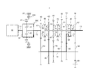
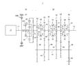
- FIG. 1 is a skeleton diagram showing a transmission according to the present embodiment.
- FIG. 2 is a diagram illustrating a first-speed power transmission path of the transmission according to the present embodiment.
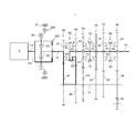
- FIG. 3 is a view for explaining a second-speed power transmission path of the transmission according to the present embodiment.
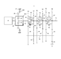
- FIG. 4 is a diagram for explaining a third speed power transmission path of the transmission according to the present embodiment.
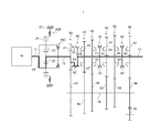
- FIG. 5 is a diagram for explaining a 4-speed power transmission path of the transmission according to the present embodiment.
- FIG. 6 is a diagram for explaining a fifth-speed power transmission path of the transmission according to the present embodiment.
- FIG. 7 is a diagram for explaining a 6-speed power transmission path of the transmission according to the present embodiment.
- FIG. 1 is a skeleton diagram showing a transmission according to the present embodiment.
- FIG. 2 is a diagram illustrating a first-speed power transmission path of the transmission according to the present embodiment.
- FIG. 3 is a view for explaining a second-speed power transmission path
- FIG. 8 is a view for explaining a seventh-speed power transmission path of the transmission according to the present embodiment.
- FIG. 9 is a skeleton diagram showing a transmission according to another embodiment.
- FIG. 10 is a skeleton diagram showing a transmission according to another embodiment.
- FIG. 11 is a table for explaining detailed settings of the gear ratios of the transmission according to the present embodiment and the final gear ratio of each gear stage.
- the transmission 1 of this embodiment includes a planetary gear mechanism 20 as a sub-transmission and a main transmission 30 in order from the input side.
- reference numeral 10 denotes an engine as a drive source
- reference numeral 11 denotes a crankshaft (hereinafter referred to as an input shaft) of the engine 10.
- the planetary gear mechanism 20 is a speed increasing planetary gear, and is arranged concentrically with the input / output shaft 12 coaxially arranged with the input shaft 11, the sun gear 22 fixed to the input / output shaft 12, and the sun gear 22.
- the sun gear 22, the ring gear 25, and the pinion gear 23 correspond to the gear group of the present disclosure
- the brake 26B corresponds to the first engagement mechanism of the present disclosure
- the clutch 26C corresponds to the second engagement mechanism of the present disclosure.
- the brake 26B is preferably a wet multi-plate clutch, and is provided between the ring gear 25 and a fixed portion 27 such as a transmission case.
- a hydraulic control circuit not shown
- the clutch plates are pressed into contact with each other
- the brake 26B enters an “engaged state” in which the ring gear 25 is engaged with the fixed portion 27 to stop the rotation.
- the brake 26B is switched to a “released state” that allows the ring gear 25 to rotate. .
- the clutch 26C is preferably a wet multi-plate clutch, and is provided between the carrier 24 and the input / output shaft 12.
- the clutch 26C engages the carrier 24 with the input / output shaft 12 to connect the input shaft 11 and the input / output shaft 12 to each other.
- An “engaged state” is established for direct connection.
- the clutch 26C enters a “release state” in which the direct connection between the input shaft 11 and the input / output shaft 12 is released. It can be switched.
- the main transmission 30 includes an output shaft 13 disposed coaxially with the input / output shaft 12, a counter shaft 14 disposed in parallel with the input / output shaft 12 and the output shaft 13, a primary gear train 40, and a fourth gear.
- the primary gear train 40 is an example of the input gear train of the present disclosure.
- the primary gear train 40 is provided so as to be integrally rotatable with the input / output shaft 12 and the counter shaft 14 is integrally rotatable.
- a primary counter gear 42 that always meshes with the gear 41 is provided.
- the 4-speed gear train 43 is an example of the output gear train of the present disclosure.
- the 4-speed gear train 43 is provided on the output shaft 13 so as to be rotatable relative to the output shaft 13 and the counter shaft 14 is integrally rotatable.
- a 4-speed counter gear 45 that always meshes with the 4-speed main gear 44;
- the third-speed gear train 46 is an example of the output gear train of the present disclosure, and is provided with a third-speed main gear 47 provided on the output shaft 13 so as to be relatively rotatable and on the counter shaft 14 so as to be integrally rotatable. And a third-speed counter gear 48 that always meshes with the third-speed main gear 47.
- the second-speed gear train 50 is an example of the output gear train of the present disclosure, and is provided so as to be integrally rotatable with the counter-shaft 14 and the second-speed main gear 51 that is relatively rotatable with the output shaft 13.
- a second-speed counter gear 52 that always meshes with the second-speed main gear 51;
- the first-speed gear train 53 is an example of the output gear train of the present disclosure.
- the first-speed gear train 53 is provided on the output shaft 13 so as to be rotatable relative to the output shaft 13 and on the counter shaft 14 so as to be integrally rotatable.
- a first-speed counter gear 55 that always meshes with the first-speed main gear 54.
- the reverse gear train 56 is an example of the output gear train of the present disclosure.
- the reverse gear train 57 is provided on the output shaft 13 so as to be relatively rotatable, and is provided on the counter shaft 14 so as to be integrally rotatable.
- a reverse counter gear 58 that is always meshed with the main gear 57 and an idler gear 59 that is always meshed with the reverse counter gear 58 are included.
- the first sync mechanism 60 meshes with a first sync hub 61 provided on the output shaft 13 between the primary main gear 41 and the 4-speed main gear 44 so as to be integrally rotatable, and with the outer peripheral teeth of the first sync hub 61.
- a first sync sleeve 62 having inner peripheral teeth, a 5/7 speed dog gear 63 provided integrally with the primary main gear 41, and a 4/4 provided integrally with the fourth speed main gear 44.
- a 6-speed dog gear 64 and a synchronizer ring (not shown) provided between the first sync hub 61 and the dog gears 63 and 64 are provided.
- the first sync mechanism 60 selects the primary main gear 41 or the fourth-speed main gear 44 as the output shaft 13 by shifting the first sync sleeve 61 by a shift fork (not shown) and meshing with the dog gears 63 and 64. Synchronously coupled (gear-in).
- the second synchro mechanism 70 includes a second sync hub 71 provided on the output shaft 13 between the third-speed main gear 47 and the second-speed main gear 51 so as to be integrally rotatable, and outer peripheral teeth of the second sync hub 71.
- a second sync sleeve 72 having inner teeth that mesh with the third gear, a third-speed dog gear 73 provided integrally with the third-speed main gear 47, and a second-speed main gear 51 provided so as to be integrally rotatable.
- a second-speed dog gear 74 and a synchronizer ring (not shown) provided between the second sync hub 71 and the dog gears 73 and 74 are provided.
- the second sync mechanism 70 shifts the second sync sleeve 71 by a shift fork (not shown) and meshes with the dog gears 73 and 74, so that the third-speed main gear 47 or the second-speed main gear 51 is connected to the output shaft 13.
- a shift fork not shown
- the second sync mechanism 70 is configured so that the counter shaft 14 is provided if the third-speed main gear 47 and the second-speed main gear 51 are fixed gears, and the third-speed counter gear 48 and the second-speed counter gear 51 are idle gears. It may be provided on the side.
- the third synchronization mechanism 80 includes a third synchronization hub 81 provided on the output shaft 13 between the first-speed main gear 54 and the reverse main gear 57 so as to be integrally rotatable, and outer peripheral teeth of the third synchronization hub 81.
- a third sync sleeve 82 having meshing inner teeth, a first-speed dog gear 83 provided integrally with the first-speed main gear 54, and a reverse provided integrally with the reverse-speed main gear 57 Dog gear 84, and a third synchronizer hub 81 and a synchronizer ring (not shown) provided between dog gears 83 and 84, respectively.
- the third sync mechanism 80 shifts the third sync sleeve 81 by a shift fork (not shown) and meshes with each of the dog gears 83 and 84, so that the first speed main gear 54 or the reverse main gear 57 is used as the output shaft 13.
- a synchronous coupling (gear-in) is selectively performed.
- the third sync mechanism 80 is arranged on the counter shaft 14 side if the first-speed main gear 54 and the reverse main gear 57 are fixed gears, and the first-speed counter gear 55 and the reverse counter gear 58 are idle gears. It may be provided.
- FIG. 2 shows a first-speed power transmission path.
- the brake 26B is selected to be in the “released state” and the clutch 26C is selected to be in the “engaged state”, and the first speed main gear 54 and the output shaft 13 are coupled by the third sync mechanism 80. That is, the power of the engine 10 is transmitted to the input shaft 11 ⁇ carrier 24 ⁇ clutch 26 C ⁇ input / output shaft 12 ⁇ primary gear train 40 ⁇ counter shaft 14, first speed gear train 53 ⁇ third sync mechanism 80 ⁇ output shaft 13.
- a first-speed power transmission path is established.
- the clutch 26C can also be used as a first speed start clutch. be able to.
- FIG. 3 shows a second speed power transmission path.
- the brake 26B is selected to be in the “released state” and the clutch 26C is selected to be in the “engaged state”, and the second-speed main gear 51 and the output shaft 13 are coupled by the second sync mechanism 70. That is, the power of the engine 10 is transmitted to the input shaft 11 ⁇ the carrier 24 ⁇ the clutch 26C ⁇ the input / output shaft 12 ⁇ the primary gear train 40 ⁇ the counter shaft 14 ⁇ the second gear train 50 ⁇ the second sync mechanism 70 ⁇ the output shaft 13.
- a second-speed power transmission path is established.
- the clutch 26C is also used as a clutch for the second speed start. be able to.
- FIG. 4 shows a third speed power transmission path.
- the brake 26B is selected to be “released state” and the clutch 26C is selected to be “engaged state”, and the third speed main gear 47 and the output shaft 13 are coupled by the second sync mechanism 70. That is, the motive power of the engine 10 is transmitted to the input shaft 11 ⁇ the carrier 24 ⁇ the clutch 26C ⁇ the input / output shaft 12 ⁇ the primary gear train 40 ⁇ the counter shaft 14 ⁇ the third gear train 46 ⁇ the second sync mechanism 70 ⁇ the output shaft 13.
- a third-speed power transmission path is established.
- FIG. 5 shows a 4-speed power transmission path.
- the brake 26B is selected to be in the “released state” and the clutch 26C is selected to be in the “engaged state”, and the main gear 44 for the fourth speed and the output shaft 13 are coupled by the first sync mechanism 60. That is, the motive power of the engine 10 is transmitted to the input shaft 11 ⁇ the carrier 24 ⁇ the clutch 26C ⁇ the input / output shaft 12 ⁇ the primary gear train 40 ⁇ the counter shaft 14 ⁇ the 4-speed gear train 43 ⁇ the first sync mechanism 60 ⁇ the output shaft 13.
- a 4-speed power transmission path is established.
- FIG. 6 shows a 5-speed power transmission path.
- the brake 26B is selected to be in the “released state” and the clutch 26C is selected to be in the “engaged state”, and the primary main gear 41 and the output shaft 13 are coupled by the first sync mechanism 60, 11, the input / output shaft 12 and the output shaft 13 are directly connected. That is, the power of the engine 10 is transmitted to the input shaft 11 ⁇ carrier 24 ⁇ clutch 26 ⁇ / b> C ⁇ input / output shaft 12 ⁇ primary main gear 41 ⁇ first sync mechanism 60 ⁇ output shaft 13, so that a 5-speed power transmission path is established. Has been established.
- FIG. 7 shows a 6-speed power transmission path.
- the brake 26B is selected to be “engaged” and the clutch 26C is selected to be “released”, and the first sync mechanism 60 causes the 4th speed main gear 44 to pass through the 4 / 6th speed dog gear 64.
- the output shaft 13 is coupled. That is, after the power of the engine 10 is increased through the input shaft 11 ⁇ the carrier 24 ⁇ the pinion gear 23 ⁇ the sun gear 22, the input / output shaft 12 ⁇ the primary gear train 40 ⁇ the counter shaft 14 ⁇ the fourth gear train 43 ⁇
- a 6th-speed power transmission path is established.
- FIG. 8 shows a 7-speed power transmission path.
- the brake 26B is selected to be “engaged” and the clutch 26C is selected to be “released”, and the primary main gear 41 and the output shaft 13 are coupled by the first sync mechanism 60, The shaft 12 and the output shaft 13 are directly connected. That is, the power of the engine 10 is increased through the input shaft 11 ⁇ carrier 24 ⁇ pinion gear 23 ⁇ sun gear 22, and then transmitted to the input / output shaft 12 ⁇ primary main gear 41 ⁇ first sync mechanism 60 ⁇ output shaft 13. As a result, a 7-speed power transmission path is established.
- the gear ratio of the planetary gear mechanism 20 is set to 0.55. Further, the gear ratio of each transmission gear train of the main transmission 30 is 5.979 for the first gear train 53 and the gear train 50 for the second gear when the gear ratio of the primary gear train 40 is 1.0. Is 3.434, the third gear set 46 is set to 2.040, and the fourth gear set 43 is set to 1.379.
- the brake 26B of the planetary gear mechanism 20 is set to the “released state” and the clutch 26C is set to the “engaged state” so that the input shaft 11 and the input / output shaft 12 are directly connected (5th speed).
- the final gear ratio of each gear stage becomes the same value as the gear ratio of each gear train.
- the final gear ratio of each gear stage is determined by the planetary gear mechanism 20 by setting the brake 26B of the planetary gear mechanism 20 to the “engaged state” and the clutch 26C to the “released state”. Increased value.
- the planetary gear mechanism 20 is configured to be able to effectively expand the number of gears and the gear ratio ratio without causing an increase in the gear train for shifting by switching directly to a low gear and increasing to a high gear. . Further, when starting at the first and second speeds, the clutch 26C is gradually connected and completely engaged from the half-clutch state, so that the clutch 26C can also be used as a starting clutch.
- the speed change planetary gear mechanism 20 is provided on the input side of the main transmission 30, so that the speed change gear train is provided to the main transmission 30.
- Multi-stage transmission 1 can be achieved without adding.
- the clutch 26C of the planetary gear mechanism 20 is gradually connected and completely engaged from the half-clutch state, so that the clutch 26C can be used as a starting clutch.
- the clutch device and torque converter of the conventional structure it becomes possible to omit the clutch device and torque converter of the conventional structure, and the weight and the total length of the entire device can be effectively reduced as compared with the conventional structure.
- the torque increased by the main transmission is transmitted to the planetary gear mechanism at the low speed stage, so it is necessary to ensure a large brake capacity.
- the planetary gear mechanism 20 is arranged on the input side of the main transmission 30, transmission of increased torque unlike the conventional structure does not occur, so that the capacity of the brake 26 ⁇ / b> B and the clutch 26 ⁇ / b> C is reduced. Can be kept small, and an increase in the size of the planetary gear mechanism 20 can be effectively prevented.
- the carrier 24 is connected to the input shaft 11
- the ring gear 25 is connected to the input / output shaft 12
- the brake 26B fixes the sun gear 22.
- a possible single pinion type planetary gear mechanism may be used.
- a double pinion type planetary gear mechanism in which the ring gear 25 is connected to the input shaft 11 and the sun gear 22 is connected to the input / output shaft 12 as shown in FIG. In any of these cases, the same operational effects as in the above embodiment can be obtained.
- brake 26B and the clutch 26C are not limited to the wet multi-plate clutch, and a wet single-plate clutch or the like can also be applied.
Landscapes
- Engineering & Computer Science (AREA)
- General Engineering & Computer Science (AREA)
- Mechanical Engineering (AREA)
- Structure Of Transmissions (AREA)
- Hydraulic Clutches, Magnetic Clutches, Fluid Clutches, And Fluid Joints (AREA)
Abstract
入力軸、入力軸から動力が伝達されるギヤ群、キャリア及び、ギヤ群から動力が伝達される入出力軸を含む遊星歯車機構と、ギヤの回転を停止させる係合状態又は、ギヤの回転を許容する解除状態に切り替え可能なブレーキと、ギヤをキャリアと係合させて一体回転させる係合状態又は、ギヤとキャリアとの係合を解除する解除状態に切り替え可能なクラッチと、出力軸、カウンタ軸、入力ギヤ列及び、複数の出力ギヤ列を含む主変速機とを備えた。
Description
本開示は、変速機に関し、特に、遊星歯車機構を備えた多段変速機に関する。
一般的に、変速機の多段化を変速ギヤ列の追加によって行うと、装置全体の重量増加や全長増加等を招くことになる。このような変速ギヤ列の追加を行うことなく多段化を図る構造として、主変速機の出力側に副変速機としての遊星歯車機構を配置し、遊星歯車機構を高速又は低速に切り替えるようにした多段変速機が広く実用化されている(例えば、特許文献1,2参照)。
一般的に、主変速機の入力側には、駆動源から主変速機への動力伝達を断接するクラッチ装置やトルクの増幅作用を発生させるトルクコンバータ等が設けられている。このため、主変速機の出力側に遊星歯車機構を設けた構造では、入力側のクラッチ装置やトルクコンバータに加え、遊星歯車機構を高速又は低速に切り替えるブレーキ及びクラッチも必要となり、部品点数の増加に伴う重量増加や全長増加、コスト上昇等を招く。
また、主変速機の出力側に遊星歯車機構を設けた構造では、主変速機から遊星歯車機構に伝達されるトルクは、低速段時に主変速機によって増大されることになる。このため、増大されたトルクに対して、遊星歯車機構を低速に切り替えるブレーキの圧接力を十分に確保するには、クラッチプレートの容量を大きくする必要があり、遊星歯車機構の大型化を招く。
本開示は、変速機の多段化を図りつつ、重量増加や全長増加を効果的に抑制する。
本開示の技術は、駆動源から動力が伝達される入力軸、該入力軸から動力が伝達されるギヤ群、該ギヤ群のうち一部のギヤ群を回転可能に支持するキャリア及び、前記ギヤ群から動力が伝達される入出力軸を含む遊星歯車機構と、前記ギヤ群のうち一のギヤと係合して当該一のギヤの回転を停止させる係合状態又は、前記一のギヤの回転を許容する解除状態に切り替え可能な第1係合機構と、前記ギヤ群のうち前記一のギヤとは異なる他のギヤを前記キャリアと係合させて一体回転させる係合状態又は、前記他のギヤと前記キャリアとの係合を解除する解除状態に切り替え可能な第2係合機構と、前記入出力軸と同軸上に配置された出力軸、該出力軸と平行に配置されたカウンタ軸、前記入出力軸と前記カウンタ軸とに設けられた入力ギヤ列及び、前記出力軸と前記カウンタ軸とに設けられた複数の出力ギヤ列を含む主変速機とを備えることを特徴とする。
また、所定の低速段にて、前記第1係合機構が解除状態、前記第2係合機構が係合状態に選択されて、前記入力軸と前記入出力軸とが直結され、所定の高速段にて、前記第1係合機構が係合状態、前記第2係合機構が解除状態に選択されて、前記入力軸に伝達される動力が前記入出力軸に増速されて伝達されることが好ましい。
また、前記第2係合機構は湿式多板クラッチであって、当該湿式多板クラッチが所定の発進段にて半クラッチ状態を経由して完接されてもよい。
また、前記遊星歯車機構は、前記入出力軸に固定されたサンギヤと、該サンギヤと同心に配置されたリングギヤと、前記サンギヤ及び前記リングギヤと噛合する複数のピニオンギヤと、前記入力軸に固定されると共に、前記ピニオンギヤを回転可能に支持するキャリアとを含み、前記第1係合機構は、係合状態で前記リングギヤの回転を停止させ、前記第2係合機構は、係合状態で前記キャリアと前記入出力軸とを一体回転させてもよい。
本開示の技術によれば、変速機の多段化を図りつつ、重量増加や全長増加を効果的に抑制することができる。
以下、添付図面に基づいて、本開示の一実施形態に係る変速機を説明する。
図1に示すように、本実施形態の変速機1は、入力側から順に副変速機としての遊星歯車機構20と、主変速機30とを備えている。なお、図中において、符号10は駆動源としてのエンジン、符号11はエンジン10のクランク軸(以下、入力軸という)をそれぞれ示している。
遊星歯車機構20は、増速用遊星歯車であって、入力軸11と同軸上に配置された入出力軸12と、入出力軸12に固定されたサンギヤ22と、サンギヤ22と同心に配置されたリングギヤ25と、サンギヤ22及びリングギヤ25と噛合する複数のピニオンギヤ23と、入力軸11に固定されると共に、各ピニオンギヤ23を自転及び公転自在に支持するキャリア24と、ブレーキ26Bと、クラッチ26Cとを備えている。なお、サンギヤ22、リングギヤ25、ピニオンギヤ23は、本開示のギヤ群、ブレーキ26Bは本開示の第1係合機構、クラッチ26Cは本開示の第2係合機構に相当する。
ブレーキ26Bは、好ましくは、湿式多板クラッチであって、リングギヤ25と変速機ケース等の固定部27との間に設けられている。ブレーキ26Bは、図示を省略する油圧制御回路から作動油が供給されて各クラッチプレートが圧接されると、リングギヤ25を固定部27に係合させて回転を停止させる「係合状態」になる。一方、ブレーキ26Bは、作動油の供給が停止されて各クラッチプレートが図示しないリターンスプリングの付勢力によって離反されると、リングギヤ25の回転を許容する「解除状態」に切り替えられるようになっている。
クラッチ26Cは、好ましくは、湿式多板クラッチであって、キャリア24と入出力軸12との間に設けられている。クラッチ26Cは、図示を省略する油圧制御回路から作動油が供給されて各クラッチプレートが圧接されると、キャリア24を入出力軸12に係合させて、入力軸11と入出力軸12とを直結させる「係合状態」になる。一方、クラッチ26Cは、作動油の供給が停止されて各クラッチプレートが図示しないリターンスプリングの付勢力によって離反されると、入力軸11と入出力軸12との直結を解除する「解除状態」に切り替えられるようになっている。
主変速機30は、入出力軸12と同軸上に配置された出力軸13と、入出力軸12及び出力軸13と平行に配置されたカウンタ軸14と、プライマリギヤ列40と、4速用ギヤ列43と、3速用ギヤ列46と、2速用ギヤ列50と、1速用ギヤ列53と、リバース用ギヤ列56と、第1シンクロ機構60と、第2シンクロ機構70と、第3シンクロ機構80とを備えている。
プライマリギヤ列40は、本開示の入力ギヤ列の一例であって、入出力軸12に一体回転可能に設けられたプライマリ主ギヤ41と、カウンタ軸14に一体回転可能に設けられて、プライマリ主ギヤ41と常時噛合するプライマリカウンタギヤ42とを有する。
4速用ギヤ列43は、本開示の出力ギヤ列の一例であって、出力軸13に相対回転可能に設けられた4速用主ギヤ44と、カウンタ軸14に一体回転可能に設けられて、4速用主ギヤ44と常時噛合する4速用カウンタギヤ45とを有する。
3速用ギヤ列46は、本開示の出力ギヤ列の一例であって、出力軸13に相対回転可能に設けられた3速用主ギヤ47と、カウンタ軸14に一体回転可能に設けられて、3速用主ギヤ47と常時噛合する3速用カウンタギヤ48とを有する。
2速用ギヤ列50は、本開示の出力ギヤ列の一例であって、出力軸13に相対回転可能に設けられた2速用主ギヤ51と、カウンタ軸14に一体回転可能に設けられて、2速用主ギヤ51と常時噛合する2速用カウンタギヤ52とを有する。
1速用ギヤ列53は、本開示の出力ギヤ列の一例であって、出力軸13に相対回転可能に設けられた1速用主ギヤ54と、カウンタ軸14に一体回転可能に設けられて、1速用主ギヤ54と常時噛合する1速用カウンタギヤ55とを有する。
リバース用ギヤ列56は、本開示の出力ギヤ列の一例であって、出力軸13に相対回転可能に設けられたリバース用主ギヤ57と、カウンタ軸14に一体回転可能に設けられて、リバース用主ギヤ57と常時噛合するリバース用カウンタギヤ58と、リバース用カウンタギヤ58と常時噛合するアイドラギヤ59とを有する。
第1シンクロ機構60は、プライマリ主ギヤ41と4速用主ギヤ44との間の出力軸13に一体回転可能に設けられた第1シンクロハブ61と、第1シンクロハブ61の外周歯と噛合する内周歯を有する第1シンクロスリーブ62と、プライマリ主ギヤ41に一体回転可能に設けられた5/7速用ドグギヤ63と、4速用主ギヤ44に一体回転可能に設けられた4/6速用ドグギヤ64と、第1シンクロハブ61と各ドグギヤ63,64との間にそれぞれ設けられた図示しないシンクロナイザリングとを備えている。
第1シンクロ機構60は、図示しないシフトフォークによって第1シンクロスリーブ61がシフト移動されて各ドグギヤ63,64と噛合することで、プライマリ主ギヤ41又は4速用主ギヤ44を出力軸13に選択的に同期結合(ギヤイン)させるようになっている。
第2シンクロ機構70は、3速用主ギヤ47と2速用主ギヤ51との間の出力軸13に一体回転可能に設けられた第2シンクロハブ71と、第2シンクロハブ71の外周歯と噛合する内周歯を有する第2シンクロスリーブ72と、3速用主ギヤ47に一体回転可能に設けられた3速用ドグギヤ73と、2速用主ギヤ51に一体回転可能に設けられた2速用ドグギヤ74と、第2シンクロハブ71と各ドグギヤ73,74との間にそれぞれ設けられた図示しないシンクロナイザリングとを備えている。
第2シンクロ機構70は、図示しないシフトフォークによって第2シンクロスリーブ71がシフト移動されて各ドグギヤ73,74と噛合することで、3速用主ギヤ47又は2速用主ギヤ51を出力軸13に選択的に同期結合(ギヤイン)させるようになっている。なお、第2シンクロ機構70は、3速用主ギヤ47及び2速用主ギヤ51を固定ギヤ、3速用カウンタギヤ48及び2速用カウンタギヤ51を遊転ギヤとすれば、カウンタ軸14側に設けられてもよい。
第3シンクロ機構80は、1速用主ギヤ54とリバース用主ギヤ57との間の出力軸13に一体回転可能に設けられた第3シンクロハブ81と、第3シンクロハブ81の外周歯と噛合する内周歯を有する第3シンクロスリーブ82と、1速用主ギヤ54に一体回転可能に設けられた1速用ドグギヤ83と、リバース速用主ギヤ57に一体回転可能に設けられたリバース用ドグギヤ84と、第3シンクロハブ81と各ドグギヤ83,84との間にそれぞれ設けられた図示しないシンクロナイザリングとを備えている。
第3シンクロ機構80は、図示しないシフトフォークによって第3シンクロスリーブ81がシフト移動されて各ドグギヤ83,84と噛合することで、1速用主ギヤ54又はリバース用主ギヤ57を出力軸13に選択的に同期結合(ギヤイン)させるようになっている。なお、第3シンクロ機構80は、1速用主ギヤ54及びリバース用主ギヤ57を固定ギヤ、1速用カウンタギヤ55及びリバース用カウンタギヤ58を遊転ギヤとすれば、カウンタ軸14側に設けられてもよい。
次に、本実施形態の変速機1による各前進段の動力伝達経路を図2~8に基づいて説明する。
図2は、1速の動力伝達経路を示している。1速の場合は、ブレーキ26Bが「解除状態」、クラッチ26Cが「係合状態」に選択されると共に、第3シンクロ機構80によって1速用主ギヤ54と出力軸13とが結合される。すなわち、エンジン10の動力が入力軸11→キャリア24→クラッチ26C→入出力軸12→プライマリギヤ列40→カウンタ軸14、1速用ギヤ列53→第3シンクロ機構80→出力軸13に伝達されることで、1速の動力伝達経路が確立されるようになっている。1速発進時には、1速の動力伝達経路を確立した状態で、クラッチ26Cを徐々に接続すると共に半クラッチ状態を経由して完接させれば、クラッチ26Cを1速発進用のクラッチとして兼用することができる。
図3は、2速の動力伝達経路を示している。2速の場合は、ブレーキ26Bが「解除状態」、クラッチ26Cが「係合状態」に選択されると共に、第2シンクロ機構70によって2速用主ギヤ51と出力軸13とが結合される。すなわち、エンジン10の動力が入力軸11→キャリア24→クラッチ26C→入出力軸12→プライマリギヤ列40→カウンタ軸14→2速用ギヤ列50→第2シンクロ機構70→出力軸13に伝達されることで、2速の動力伝達経路が確立されるようになっている。2速発進時には、2速の動力伝達経路を確立した状態で、クラッチ26Cを徐々に接続すると共に半クラッチ状態を経由して完接させれば、クラッチ26Cを2速発進用のクラッチとして兼用することができる。
図4は、3速の動力伝達経路を示している。3速の場合は、ブレーキ26Bが「解除状態」、クラッチ26Cが「係合状態」に選択されると共に、第2シンクロ機構70によって3速用主ギヤ47と出力軸13とが結合される。すなわち、エンジン10の動力が入力軸11→キャリア24→クラッチ26C→入出力軸12→プライマリギヤ列40→カウンタ軸14→3速用ギヤ列46→第2シンクロ機構70→出力軸13に伝達されることで、3速の動力伝達経路が確立されるようになっている。
図5は、4速の動力伝達経路を示している。4速の場合は、ブレーキ26Bが「解除状態」、クラッチ26Cが「係合状態」に選択されると共に、第1シンクロ機構60によって4速用主ギヤ44と出力軸13とが結合される。すなわち、エンジン10の動力が入力軸11→キャリア24→クラッチ26C→入出力軸12→プライマリギヤ列40→カウンタ軸14→4速用ギヤ列43→第1シンクロ機構60→出力軸13に伝達されることで、4速の動力伝達経路が確立されるようになっている。
図6は、5速の動力伝達経路を示している。5速の場合は、ブレーキ26Bが「解除状態」、クラッチ26Cが「係合状態」に選択されると共に、第1シンクロ機構60によってプライマリ主ギヤ41と出力軸13とが結合されて、入力軸11、入出力軸12及び、出力軸13が直結状態にされる。すなわち、エンジン10の動力が入力軸11→キャリア24→クラッチ26C→入出力軸12→プライマリ主ギヤ41→第1シンクロ機構60→出力軸13に伝達されることで、5速の動力伝達経路が確立されるようになっている。
図7は、6速の動力伝達経路を示している。6速の場合は、ブレーキ26Bが「係合状態」、クラッチ26Cが「解除状態」に選択されると共に、第1シンクロ機構60によって4速用主ギヤ44が4/6速用ドグギヤ64を介して出力軸13とが結合される。すなわち、エンジン10の動力が入力軸11→キャリア24→ピニオンギヤ23→サンギヤ22を経由して増速された後、入出力軸12→プライマリギヤ列40→カウンタ軸14→4速用ギヤ列43→第1シンクロ機構60→出力軸13に伝達されることで、6速の動力伝達経路が確立されるようになっている。
図8は、7速の動力伝達経路を示している。7速の場合は、ブレーキ26Bが「係合状態」、クラッチ26Cが「解除状態」に選択されると共に、第1シンクロ機構60によってプライマリ主ギヤ41と出力軸13とが結合されて、入出力軸12及び、出力軸13が直結状態にされる。すなわち、エンジン10の動力が入力軸11→キャリア24→ピニオンギヤ23→サンギヤ22を経由して増速された後、入出力軸12→プライマリ主ギヤ41→第1シンクロ機構60→出力軸13に伝達されることで、7速の動力伝達経路が確立されるようになっている。
次に、図11に基づいて、本実施形態に係る変速機1の各ギヤ比及び各変速段の最終変速比の詳細設定について説明する。なお、以下の説明に用いる各数値は、本実施形態の好適な一例であって、本開示の趣旨を一脱しない範囲で他の値に設定することが可能である。
図11に示すように、遊星歯車機構20のギヤ比は0.55に設定されている。また、主変速機30の各変速用ギヤ列のギヤ比は、プライマリギヤ列40のギヤ比を1.0とした場合に、1速用ギヤ列53が5.979、2速用ギヤ列50が3.434、3速用ギヤ列46が2.040、4速用ギヤ列43が1.379で設定されている。1~5速までの低速段領域では、遊星歯車機構20のブレーキ26Bを「解除状態」、クラッチ26Cを「係合状態」にして、入力軸11と入出力軸12とを直結状態(5速は出力軸13も直結)とすることで、各変速段の最終変速比は各変速用ギヤ列のギヤ比と同値になる。一方、6速以降の高速段領域では、遊星歯車機構20のブレーキ26Bを「係合状態」、クラッチ26Cを「解除状態」にすることで、各変速段の最終変速比は遊星歯車機構20によって増速された値になる。
すなわち、遊星歯車機構20を低速段では直結、高速段では増速に切り替えることで、変速用ギヤ列の増加を招くことなく変速段数及び変速比幅を効果的に拡張できるように構成されている。また、1・2速発進時には、クラッチ26Cを徐々に接続して半クラッチ状態から完接させることで、クラッチ26Cを発進用のクラッチとして兼用できるように構成されている。
以上詳述したように、本実施形態の変速機1によれば、主変速機30の入力側に増速用の遊星歯車機構20を設けたことで、主変速機30に変速用ギヤ列を追加することなく変速機1の多段化を図ることができる。
また、発進時には、遊星歯車機構20のクラッチ26Cを徐々に接続して半クラッチ状態から完接させることで、クラッチ26Cを発進用のクラッチに兼用することができる。これにより、従来構造のクラッチ装置やトルクコンバータを省略することが可能となり、従来構造よりも装置全体の重量や全長を効果的に減少させることができる。
また、遊星歯車機構を主変速機の出力側に配置した従来構造では、低速段時に主変速機によって増大されたトルクが遊星歯車機構に伝達されるため、ブレーキ容量を大きく確保する必要がある。これに対し、本実施形態では、遊星歯車機構20を主変速機30の入力側に配置したことで、従来構造のような増大されたトルクの伝達が生じないため、ブレーキ26Bやクラッチ26Cの容量を小さく抑えることが可能となり、遊星歯車機構20の大型化を効果的に防止することができる。
なお、本開示は、上述の実施形態に限定されるものではなく、本開示の趣旨を逸脱しない範囲で、適宜変形して実施することが可能である。
例えば、遊星歯車機構20は、増速用であれば、図9に示すように、キャリア24が入力軸11に接続され、リングギヤ25が入出力軸12に接続され、ブレーキ26Bがサンギヤ22を固定可能なシングルピニオン型の遊星歯車機構であってもよい。或いは、図10に示すような、リングギヤ25が入力軸11に接続され、サンギヤ22が入出力軸12に接続されたダブルピニオン型の遊星歯車機構であってもよい。これら何れの場合も上記実施形態と同様の作用効果を奏することができる。
また、上記実施形態では、変速段は計7段として説明したが、遊星歯車機構20やプライマリギヤ列40、各変速用ギヤ列43,46,50,53のギヤ比を適宜調整することで、計8~10段の変速段を設定してもよい。
また、ブレーキ26Bやクラッチ26Cは、湿式多板クラッチに限定されず、湿式単板クラッチ等を適用することもできる。
本出願は、2016年8月31日付で出願された日本国特許出願(特願2016-169407)に基づくものであり、その内容はここに参照として取り込まれる。
本開示の技術によれば、変速機の多段化を図りつつ、重量増加や全長増加を効果的に抑制することができる。
1 変速機
10 エンジン
11 入力軸
12 入出力軸
13 出力軸
14 カウンタ軸
20 遊星歯車機構
22 サンギヤ
23 ピニオンギヤ
24 キャリア
25 リングギヤ
26B ブレーキ
26C クラッチ
30 主変速機
40 プライマリギヤ列
43 4速用ギヤ列
46 3速用ギヤ列
50 2速用ギヤ列
53 1速用ギヤ列
56 リバース用ギヤ列
60 第1シンクロ機構
70 第2シンクロ機構
80 第3シンクロ機構
10 エンジン
11 入力軸
12 入出力軸
13 出力軸
14 カウンタ軸
20 遊星歯車機構
22 サンギヤ
23 ピニオンギヤ
24 キャリア
25 リングギヤ
26B ブレーキ
26C クラッチ
30 主変速機
40 プライマリギヤ列
43 4速用ギヤ列
46 3速用ギヤ列
50 2速用ギヤ列
53 1速用ギヤ列
56 リバース用ギヤ列
60 第1シンクロ機構
70 第2シンクロ機構
80 第3シンクロ機構
Claims (4)
- 駆動源から動力が伝達される入力軸、該入力軸から動力が伝達されるギヤ群、該ギヤ群のうち一部のギヤ群を回転可能に支持するキャリア及び、前記ギヤ群から動力が伝達される入出力軸を含む遊星歯車機構と、
前記ギヤ群のうち一のギヤと係合して当該一のギヤの回転を停止させる係合状態又は、前記一のギヤの回転を許容する解除状態に切り替え可能な第1係合機構と、
前記ギヤ群のうち前記一のギヤとは異なる他のギヤを前記キャリアと係合させて一体回転させる係合状態又は、前記他のギヤと前記キャリアとの係合を解除する解除状態に切り替え可能な第2係合機構と、
前記入出力軸と同軸上に配置された出力軸、該出力軸と平行に配置されたカウンタ軸、前記入出力軸と前記カウンタ軸とに設けられた入力ギヤ列及び、前記出力軸と前記カウンタ軸とに設けられた複数の出力ギヤ列を含む主変速機と、を備える
ことを特徴とする変速機。 - 所定の低速段にて、前記第1係合機構が解除状態、前記第2係合機構が係合状態に選択されて、前記入力軸と前記入出力軸とが直結され、
所定の高速段にて、前記第1係合機構が係合状態、前記第2係合機構が解除状態に選択されて、前記入力軸に伝達される動力が前記入出力軸に増速されて伝達される
請求項1に記載の変速機。 - 前記第2係合機構は湿式多板クラッチであって、当該湿式多板クラッチが所定の発進段にて半クラッチ状態を経由して完接される
請求項1又は2に記載の変速機。 - 前記遊星歯車機構は、前記入出力軸に固定されたサンギヤと、該サンギヤと同心に配置されたリングギヤと、前記サンギヤ及び前記リングギヤと噛合する複数のピニオンギヤと、前記入力軸に固定されると共に、前記ピニオンギヤを回転可能に支持するキャリアとを含み、前記第1係合機構は、係合状態で前記リングギヤの回転を停止させ、前記第2係合機構は、係合状態で前記キャリアと前記入出力軸とを一体回転させる
請求項1から3の何れか一項に記載の変速機。
Applications Claiming Priority (2)
| Application Number | Priority Date | Filing Date | Title |
|---|---|---|---|
| JP2016-169407 | 2016-08-31 | ||
| JP2016169407A JP6729191B2 (ja) | 2016-08-31 | 2016-08-31 | 変速機 |
Publications (1)
| Publication Number | Publication Date |
|---|---|
| WO2018043605A1 true WO2018043605A1 (ja) | 2018-03-08 |
Family
ID=61300940
Family Applications (1)
| Application Number | Title | Priority Date | Filing Date |
|---|---|---|---|
| PCT/JP2017/031264 Ceased WO2018043605A1 (ja) | 2016-08-31 | 2017-08-30 | 変速機 |
Country Status (2)
| Country | Link |
|---|---|
| JP (1) | JP6729191B2 (ja) |
| WO (1) | WO2018043605A1 (ja) |
Citations (3)
| Publication number | Priority date | Publication date | Assignee | Title |
|---|---|---|---|---|
| JP2002048213A (ja) * | 2000-08-01 | 2002-02-15 | Toyota Motor Corp | 無段変速機構を備えた変速機 |
| JP2002266980A (ja) * | 2001-03-05 | 2002-09-18 | Aisin Aw Co Ltd | 車両用変速機 |
| JP2004100941A (ja) * | 2002-03-05 | 2004-04-02 | Aisin Aw Co Ltd | 車両用変速機 |
-
2016
- 2016-08-31 JP JP2016169407A patent/JP6729191B2/ja not_active Expired - Fee Related
-
2017
- 2017-08-30 WO PCT/JP2017/031264 patent/WO2018043605A1/ja not_active Ceased
Patent Citations (3)
| Publication number | Priority date | Publication date | Assignee | Title |
|---|---|---|---|---|
| JP2002048213A (ja) * | 2000-08-01 | 2002-02-15 | Toyota Motor Corp | 無段変速機構を備えた変速機 |
| JP2002266980A (ja) * | 2001-03-05 | 2002-09-18 | Aisin Aw Co Ltd | 車両用変速機 |
| JP2004100941A (ja) * | 2002-03-05 | 2004-04-02 | Aisin Aw Co Ltd | 車両用変速機 |
Also Published As
| Publication number | Publication date |
|---|---|
| JP2018035874A (ja) | 2018-03-08 |
| JP6729191B2 (ja) | 2020-07-22 |
Similar Documents
| Publication | Publication Date | Title |
|---|---|---|
| US9194463B2 (en) | 10-shift power train of automatic transmission for vehicle | |
| KR101664560B1 (ko) | 차량용 다단 자동변속기 | |
| CN104373527B (zh) | 三输入离合器变速器 | |
| CN102562966A (zh) | 自动变速器 | |
| JP7209401B2 (ja) | 動力伝達装置 | |
| US9145960B2 (en) | Triple clutch multi-speed transmission | |
| JP6295604B2 (ja) | ツインクラッチ式変速機 | |
| JP2009210020A (ja) | トランスミッション | |
| JP2010216605A (ja) | トランスミッション | |
| JP2016053412A (ja) | 変速機 | |
| KR20170061266A (ko) | 직결요소를 이용한 전륜 8속 자동 변속기 | |
| CN204533385U (zh) | 自动变速器及具有该自动变速器的车辆 | |
| JP2008291893A (ja) | デュアルクラッチ式変速機 | |
| JP6221485B2 (ja) | ツインクラッチ式変速機 | |
| JP6729191B2 (ja) | 変速機 | |
| WO2018092871A1 (ja) | デュアルクラッチ式変速機 | |
| JP6733431B2 (ja) | 変速機 | |
| KR101551005B1 (ko) | 8속 듀얼클러치 트랜스미션 | |
| KR101393908B1 (ko) | 자동변속기의 6속 파워트레인 | |
| JP2009185863A (ja) | 自動変速機 | |
| JP6828327B2 (ja) | デュアルクラッチ式変速機 | |
| KR101836617B1 (ko) | 차량용 다단 dct | |
| JP2007085436A (ja) | 歯車式多段変速装置 | |
| JP6897317B2 (ja) | 変速機 | |
| JP6772742B2 (ja) | デュアルクラッチ式変速機 |
Legal Events
| Date | Code | Title | Description |
|---|---|---|---|
| 121 | Ep: the epo has been informed by wipo that ep was designated in this application |
Ref document number: 17846609 Country of ref document: EP Kind code of ref document: A1 |
|
| NENP | Non-entry into the national phase |
Ref country code: DE |
|
| 122 | Ep: pct application non-entry in european phase |
Ref document number: 17846609 Country of ref document: EP Kind code of ref document: A1 |