WO2018043253A1 - 防眩性板ガラスの製造方法 - Google Patents
防眩性板ガラスの製造方法 Download PDFInfo
- Publication number
- WO2018043253A1 WO2018043253A1 PCT/JP2017/030171 JP2017030171W WO2018043253A1 WO 2018043253 A1 WO2018043253 A1 WO 2018043253A1 JP 2017030171 W JP2017030171 W JP 2017030171W WO 2018043253 A1 WO2018043253 A1 WO 2018043253A1
- Authority
- WO
- WIPO (PCT)
- Prior art keywords
- treatment
- plate glass
- glass
- antiglare
- producing
- Prior art date
- Legal status (The legal status is an assumption and is not a legal conclusion. Google has not performed a legal analysis and makes no representation as to the accuracy of the status listed.)
- Ceased
Links
Images

Classifications
-
- C—CHEMISTRY; METALLURGY
- C03—GLASS; MINERAL OR SLAG WOOL
- C03C—CHEMICAL COMPOSITION OF GLASSES, GLAZES OR VITREOUS ENAMELS; SURFACE TREATMENT OF GLASS; SURFACE TREATMENT OF FIBRES OR FILAMENTS MADE FROM GLASS, MINERALS OR SLAGS; JOINING GLASS TO GLASS OR OTHER MATERIALS
- C03C15/00—Surface treatment of glass, not in the form of fibres or filaments, by etching
-
- G—PHYSICS
- G09—EDUCATION; CRYPTOGRAPHY; DISPLAY; ADVERTISING; SEALS
- G09F—DISPLAYING; ADVERTISING; SIGNS; LABELS OR NAME-PLATES; SEALS
- G09F9/00—Indicating arrangements for variable information in which the information is built-up on a support by selection or combination of individual elements
Definitions
- the present invention relates to a method for producing an antiglare plate glass.
- the antiglare plate glass produced by the present invention is suitable as a cover glass for solar cells, a cover glass for image display devices, and the like.
- image display devices liquid crystal displays, organic EL displays, plasma displays, etc.
- various devices TVs, personal computers, smartphones, mobile phones, etc.
- room lights fluorescent lamps, etc.
- external light such as sunlight Is reflected on the display surface
- an antiglare treatment is performed on the surface of the cover glass for an image display device.
- an antiglare treatment is also performed to prevent light damage caused by reflected light reflected from the surface of the cover glass for solar cells.
- the anti-glare treatment is a treatment for making a reflected image unclear by providing irregularities on the surface of a substrate such as a plate glass used as a cover glass and scattering incident light by the irregularities.
- Conventionally known antiglare treatments include a method of roughening the surface of a substrate by immersing it in hydrofluoric acid or the like, and a method of roughening by sandblasting or the like (Patent Document 1).
- Patent Document 1 The above-described anti-glare process has a difficulty in that the time required for the process is relatively long and the throughput is low, and a reduction required for the anti-glare process is required.
- Patent Documents 2 to 6 glass surface treatment methods using a transfer-type atmospheric pressure CVD apparatus are known (Patent Documents 2 to 6).
- hydrogen chloride (HCl) gas, hydrogen fluoride (hydrogen fluoride (HCl) is supplied from a source gas supply nozzle provided in the apparatus to a plate glass or glass ribbon conveyed at a predetermined speed in a conveyance type atmospheric pressure CVD apparatus.
- HF hydrogen fluoride
- HF hydrogen fluoride
- gas mixed with water vapor, or these gases are sprayed separately to surface-treat the glass.
- these surface treatments are aimed at increasing the haze of the plate glass and densifying the surface of the plate glass, and no attempt has been made to apply an antiglare treatment to the plate glass using a transport type atmospheric pressure CVD apparatus.
- the present invention aims to improve the throughput of the antiglare treatment on the surface of the plate glass.
- the present invention includes a first treatment in which a first gas containing hydrogen chloride (HCl) is brought into contact with one surface of a plate glass made of alkali-containing glass, and hydrogen fluoride (The second treatment containing the second gas containing HF) is brought into contact with the volume ratio (H 2 O / HF) of water vapor (H 2 O) and HF of 0.5 or less.
- the temperature of the plate glass at the time of said 2nd process implementation is 500 degreeC or more, It implements in this order, The manufacturing method of the plate glass by which one surface was anti-glare-treated was provided.
- the temperature of the plate glass during the first treatment and the second treatment is preferably 500 to 800 ° C.
- the first gas preferably has an HCl concentration of 1 to 30 vol%.
- the second gas preferably has an HF concentration of 1 to 20 vol%.
- the gas contact time of the first treatment is preferably 1 to 20 seconds.
- the gas contact time of the second treatment is preferably 5 to 50 seconds.
- the third treatment is cleaning of a surface to be treated of the plate glass.
- the method for producing an antiglare-treated plate glass of the present invention it is preferable to carry out a pretreatment for adjusting the elution amount of the alkali component on the surface of the plateglass before the first treatment.
- the pretreatment is preferably a treatment for forming a SiO 2 film or a TiO 2 film on the plate glass surface.
- the plate glass is a float plate glass, and one surface of the plate glass is a bottom surface of the float plate glass.
- At least one of the first treatment and the second treatment is performed at normal pressure.
- the first treatment and the second treatment are performed while being conveyed in a conveyance type CVD apparatus.
- 2nd gas does not contain water vapor
- an antiglare-treated plate glass of the present invention it is preferable to obtain an antiglare-treated plate glass having a surface hardness of 4H or more.
- the atmospheric pressure CVD method is used to impart an antiglare property to one surface of the plate glass
- a method for roughening the surface of the plate glass by immersing in hydrofluoric acid or the like, sandblasting of the plate glass Provided is a method for producing a plate glass that has a higher throughput than the conventional methods such as a method of roughening the surface, a high transmittance of the plate glass, and a large pencil hardness value that is an index of the surface hardness.
- the glass sheet imparted with the antiglare property according to the present invention has a low gloss (unit) value, which is an index of gloss, and is suitable as a cover glass for solar cells and a cover glass for image display devices.
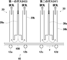
- FIG. 1 is a schematic diagram showing an example of the configuration of a transport-type atmospheric pressure CVD apparatus.
- FIG. 2A is a schematic cross-sectional view showing the plate glass after the first treatment of the present invention
- FIG. 2B is a schematic cross-sectional view showing the plate glass after the second treatment of the present invention
- FIG. 2C is a schematic cross-sectional view showing the plate glass after the third processing of the present invention to be described later.
- the antiglare treatment is performed on one surface of the plate glass in the following procedure.
- the plate glass subjected to the antiglare treatment using the method of the present invention is an alkali-containing glass such as soda lime silicate glass, alumina silicate glass, borosilicate glass or the like.
- FIG. 1 is a schematic diagram showing an example of the configuration of a transport-type atmospheric pressure CVD apparatus used in the present invention.
- the transfer-type atmospheric pressure CVD apparatus shown in FIG. 1 includes a first gas, which will be described later, from the gas supply means 20, 30 on the glass substrate 100 which is transferred in the direction of arrow y by the rollers -12a to 12d of the conveyor belt 10.
- the second gas is supplied.
- the gas supply means 20 and 30 shown in FIG. 1 are provided with exhaust parts 20b and 30b on both the upstream side and the downstream side in the traveling direction of the plate glass 100 with respect to the gas supply parts 20a and 30a.
- the first gas and the second gas supplied from the gas supply units 20a and 30a onto the plate glass 100 are sucked and removed to the exhaust units 20b and 30b through a path indicated by a dashed arrow.
- a first gas containing hydrogen chloride (HCl) is supplied from the gas supply unit 20 a of the gas supply unit 20 and is brought into contact with one surface of the plate glass 100.
- the plate glass 100 is an alkali-containing glass
- the temperature of the plate glass at the time of the first treatment is 500 ° C. or higher
- a part of the alkali component in the plate glass 100 is deposited on the surface of the plate glass as ions.
- the alkali-containing glass is soda lime silicate glass
- a part of sodium in the plate glass 100 is deposited on the surface of the plate glass 100 as sodium ions.
- the temperature of the plate glass during the first treatment is preferably 500 to 800 ° C., and more preferably 500 to 650 ° C. It is preferable to set the temperature to 650 ° C. or lower because it is easy to suppress warpage and distortion of the plate glass during the first treatment.
- the plate glass 100 before the first treatment is 500 ° C. or higher, for example, when the method of the present invention is carried out by “on-line processing”, 500 ° C. during the first treatment.
- the plate glass 100 is cooled so that it may become the above range.
- the plate glass 100 before the first treatment is less than 500 ° C., for example, when the method of the present invention is carried out by “off-line treatment”, 500 ° C. or more at the time of carrying out the first treatment.
- the plate glass 100 is heated so as to be in the range.
- the first gas supplied from the gas supply unit 20a normally contains nitrogen, dry air, and a rare gas as a carrier gas in addition to HCl. Among these, nitrogen and dry air are preferable because they are inexpensive.
- the first gas supplied from the gas supply unit 20a may contain water vapor (H 2 O) in addition to HCl and the carrier gas.
- the HCl concentration in the first gas is preferably 1-30 vol%, and more preferably 2-15 vol%.
- the gas contact time in the first treatment is preferably 1 to 20 seconds, and more preferably 2 to 12 seconds.
- a pretreatment for adjusting the precipitation amount of alkali ions (sodium ions in the case of soda lime silicate glass) on the surface of the plate glass 100 may be performed before the first treatment.
- this pretreatment include a treatment in which water vapor is brought into contact with the surface of the plate glass 100 and a treatment in which a gas containing hydrogen fluoride (HF) is brought into contact.
- HF hydrogen fluoride
- an SiO 2 film or a TiO 2 film may be formed on the surface of the plate glass 100 as a base film.
- a gas supply unit is further provided upstream of the gas supply unit 20 in the traveling direction of the plate glass 100, and a predetermined gas is supplied from the gas supply unit. Then, the plate glass 100 is brought into contact with the surface.
- water vapor is supplied from the gas supply means.
- a gas containing hydrogen fluoride (HF) is supplied from the gas supply means.
- a gas containing hydrogen fluoride (HF) is supplied from the gas supply means.
- SiO 2 film is formed on the surface of the plate glass 100 as a base film, for example, a gas containing monosilane (SiH 4 ) and a gas containing oxygen (O 2 ) are supplied from the gas supply means.
- a TiO 2 film is formed as a base film on the surface of the plate glass 100, for example, titanium chloride (TiCl 4 ) or titanium tetraisopropoxide (TTIP) is supplied from the gas supply means.
- a second gas containing hydrogen fluoride (HF) is supplied from the gas supply unit 30 a of the gas supply means 30 and is brought into contact with one surface of the plate glass 100.
- the second gas containing HF is brought into contact with one surface of the plate glass 100, the surface of the plate glass 100 is etched by HF in the second gas.
- the portion where alkali chloride is deposited on the surface of the plate glass 100 in the first treatment is not etched because the alkali chloride serves as a mask.
- unevenness is formed on the surface of the plate glass 100 by the second treatment, and the antiglare treatment is performed on the surface of the plate glass 100.
- the 2nd process is an etching process in a gaseous phase
- the temperature of the plate glass during the second treatment is preferably 500 to 800 ° C., more preferably 500 to 650 ° C. It is preferable to set the temperature to 650 ° C. or lower because it is easy to suppress warpage and distortion of the plate glass during the second treatment.
- the plate glass 100 before a 2nd process is 500 degreeC or more
- the plate glass 100 is cooled so that it may become the range of 500 degreeC or more, and before a 2nd process.
- the plate glass 100 is less than 500 ° C.
- the plate glass 100 is heated so as to be in the range of 500 ° C. or higher during the second treatment.
- FIG. 2A is a view showing the plate glass after the first treatment, and the alkali chloride 200 is deposited on the surface of the plate glass 100.
- FIG. 2B is a schematic cross-sectional view showing the plate glass surface after the second treatment. Since the alkali chloride 200 serves as a mask, only the portion where the alkali chloride 200 does not exist is etched, and the recess 110 is formed. Is formed.
- FIG. 2C is a schematic cross-sectional view showing the plate glass after the third treatment, and shows a state in which alkali chlorides existing on one surface of the plate glass 100 are removed by washing. In FIG. 2C, unevenness is formed on the surface of the plate glass 100 due to the presence of the recess 110. Due to the presence of the unevenness, the surface of the plate glass 100 is subjected to an antiglare treatment.
- the second gas supplied from the gas supply unit 30a contains water vapor (H 2 O)
- the antiglare treatment is applied to the surface of the plate glass 100 as shown in Comparative Examples 1 to 4 described later. I can't. This is because when the second gas contains water vapor (H 2 O) and the ratio thereof increases, the shape of the alkali chloride 200 deposited on the surface of the plate glass 100 changes and cannot function as an etching mask. it is conceivable that. Therefore, the second gas supplied from the gas supply unit 30a is required to have a volume ratio (H 2 O / HF) between H 2 O and HF of 0.5 or less.
- the second gas supplied from the gas supply unit 30a preferably has a volume ratio (H 2 O / HF) between H 2 O and HF of 0.1 or less. Further, it is more preferable that the volume ratio (H 2 O / HF) is 0 and the second gas does not contain water vapor (H 2 O).
- the volume ratio of 0, that is, the volume of water vapor (H 2 O) of 0 means that the volume is substantially 0. In the present embodiment, when the second gas does not actively contain water vapor (H 2 O) or contains water vapor (H 2 O) in an unavoidable amount, the volume is regarded as zero.
- the second gas supplied from the gas supply unit 30a normally contains nitrogen, dry air, and a rare gas as a carrier gas in addition to HF. Among these, nitrogen and dry air are preferable because they are inexpensive.
- the HF concentration in the second gas is preferably 1 to 20 vol%, and more preferably 2 to 15 vol%.
- the gas contact time in the second treatment is preferably 5 to 50 seconds, and more preferably 10 to 30 seconds.
- the difference in the temperature of the plate glass between the first treatment and the second treatment is preferably 0 to 50 ° C., more preferably 0 to 30 ° C.
- the first treatment or the second treatment may be higher.
- the warp distortion of the glass plate can be suppressed by reducing the difference in temperature between the plate glass of the first treatment and the second treatment.
- the method for washing the treated surface of the plate glass 100 is not particularly limited, and examples thereof include washing with water. Washing with water is preferable because it is low in cost and does not require an operation for removing the cleaning liquid after treatment.
- the plate glass 100 after the third treatment may be dried.
- the method of the present invention may be implemented as online processing or offline processing.
- on-line processing refers to a glass formed by a float method, a downdraw method, or the like when the method of the present invention is applied to a glass ribbon that moves in a float bath in a glass float forming method. This refers to the case where the method of the present invention is applied in the slow cooling process of slowly cooling the ribbon.
- off-line processing refers to performing the first processing and the second processing described above on the plate glass that has been formed and cut into a desired size.
- the plate glass in the present specification includes a glass ribbon that is formed and cut into a desired size, a glass ribbon that moves in the float bath, and a glass ribbon that is formed by a float method, a downdraw method, or the like. .
- the antiglare treatment When using the plate glass on which the antiglare treatment has been performed as the cover glass for an image display device, it is preferable to perform the antiglare treatment on the bottom surface of the float plate glass.
- the float plate glass that has been subjected to the antiglare treatment according to the method of the present invention has higher strength on the surface that has not been subjected to the antiglare treatment.
- the antiglare treatment is applied to the bottom surface of the float plate glass, the top surface not subjected to the antiglare treatment has higher strength. Therefore, when the antiglare treatment is applied to the bottom surface of the float plate glass, when the top surface having higher strength is used as the cover glass for an image display device, it can be the side facing the glass of the main body. Strength when used as glass is improved.
- the antiglare treatment of the present invention is more preferably performed in this mode, but is not limited to this mode.
- the plate glass that has been antiglare treated by the method of the present invention has good antiglare properties.
- the reflected image diffusivity index value R measured by the procedure described in the examples described later is preferably 0.05 or more, and more preferably 0.1 or more.
- the plate glass that has been subjected to the antiglare treatment by the method of the present invention changes in light transmittance as compared with that before the antiglare treatment.
- the change value ⁇ T before and after the antiglare treatment of the transmittance T measured by the procedure described in Examples described later is preferably 0.4% or more, and more preferably 1.0% or more.
- the glass sheet subjected to the antiglare treatment by the method of the present invention has low gloss.
- the glossiness (Gloss Unit (GU)) measured by the procedure described in Examples described later is preferably less than 72, and more preferably 70 or less.
- the plate glass subjected to the antiglare treatment by the method of the present invention has a higher surface hardness than the plate glass whose entire surface is HF etched.
- the pencil hardness measured by the procedure described in the examples described later is preferably 4H or higher, more preferably 7H or higher, and still more preferably 8H or higher.
- Examples 1 to 12 In the examples shown below, a plate glass of a soda lime silicate glass composition formed by the float process (the transmittance is 92.5% by the measurement based on the following evaluation method) is used, and a transport type atmospheric pressure CVD apparatus is used. The first treatment and the second treatment of the method of the present invention were performed in this order on the bottom surface of the plate glass.
- the transport type atmospheric pressure CVD apparatus has the configuration shown in FIG.
- the HCl concentration, glass temperature, and gas contact time of the first gas in the first treatment, and the second gas HF concentration, H 2 O / HF, glass temperature, and gas contact time in the second treatment are as follows: As shown in Table 1.
- the first gas is a mixed gas of HCl and nitrogen.
- the second gas is a mixed gas of HF and nitrogen.
- Comparative Examples 1 to 5 were carried out in the same procedure as in Example except that H 2 O / HF in the second treatment was more than 0.5.
- Comparative examples 6 to 10 were carried out in the same procedure as in the example except that the first treatment was not carried out.
- Transmittance T is measured by using a light receiver to place the C light source on the surface that is in contact with the gas in the first treatment and the second treatment, and to transmit the light transmitted to the opposite surface. did.
- the transmittance T was measured by the method described in JIS K7136: 2000 (ISO14782: 1999), and was measured using a haze meter (HZ-1 manufactured by Suga Test Instruments Co., Ltd.).
- the “Haze ratio” was measured by the method described in JIS K7105: 1981, and was measured using a haze meter (HZ-1 manufactured by Suga Test Instruments Co., Ltd.).
- GUI is a gloss unit (Gloss Unit), measured by a method described in JIS Z8741: 1997 (ISO2813), and measured using a spectrocolorimeter (manufactured by Konica Minolta, gloss meter GM-268Plus). did. The measurement angle was 60 °.
- R is a reflection image diffusivity index value, and is the thickness of the glass plate from the surface (hereinafter referred to as the “first surface”) on the gas contact side in the first treatment and the second treatment.
- first surface the thickness of the glass plate from the surface (hereinafter referred to as the “first surface”) on the gas contact side in the first treatment and the second treatment.
- light visible region
- the luminance of specularly reflected light referred to as 45 ° specularly reflected light
- the light receiving angle of light was changed in the range of 0 ° to + 90 °, and the brightness of the totally reflected light reflected on the first surface was measured and calculated from the following equation (1).
- Reflected image diffusivity index value R (Brightness of total reflected light-45 ° brightness of regular reflected light) / (Brightness of total reflected light) (1) “Pencil hardness” was measured by a pencil hardness test according to JIS K 5400. In addition, the description "not yet" in a table
- surface is what did not implement a pencil hardness test.
- the reflected image diffusivity index value R was 0.05 or more. Excellent antiglare property. Further, the glossiness (GU) is less than 72. The pencil hardness is 7H or higher, and the surface hardness is high. On the other hand, Comparative Examples 1 to 5 in which H 2 O / HF in the second treatment is more than 0.5 are inferior in antiglare property because the reflected image diffusivity index value R is less than 0.05. The glossiness (GU) is 72 or more. In Comparative Examples 6 to 10 in which the first treatment was not performed, the reflected image diffusivity index value R was less than 0.05, and the antiglare property was inferior. The glossiness (GU) is 72 or more. Moreover, the pencil hardness is 6H or less, and the surface hardness is low.
Landscapes
- Chemical & Material Sciences (AREA)
- Life Sciences & Earth Sciences (AREA)
- Engineering & Computer Science (AREA)
- Chemical Kinetics & Catalysis (AREA)
- General Chemical & Material Sciences (AREA)
- Geochemistry & Mineralogy (AREA)
- Materials Engineering (AREA)
- Organic Chemistry (AREA)
- Surface Treatment Of Glass (AREA)
- Devices For Indicating Variable Information By Combining Individual Elements (AREA)
Abstract
板ガラス表面の防眩処理のスループットの向上。 アルカリ含有ガラスからなる板ガラスの一方の表面に対し、塩化水素(HCl)を含有する第一のガスを接触させる第一の処理と、フッ化水素(HF)を含有する第二のガスを、水蒸気(H2O)とHFとの体積比(H2O/HF)が0.5以下で接触させる第二の処理とを、前記第一の処理および前記第二の処理実施時の板ガラスの温度が500℃以上で、この順に実施することを特徴とする、一方の表面が防眩処理された板ガラスの製造方法。
Description
本発明は、防眩性板ガラスの製造方法に関する。本発明により製造される防眩性板ガラスは、太陽電池用カバーガラス、画像表示装置用カバーガラスなどとして好適である。
各種機器(テレビ、パーソナルコンピュータ、スマートフォン、携帯電話等)に備え付けられた画像表示装置(液晶ディスプレイ、有機ELディスプレイ、プラズマディスプレイ等)においては、室内照明(蛍光灯等)、太陽光等の外光が表示面に映り込むと、反射像によって視認性が低下する。そこで、外光の映り込みを抑制するために、画像表示装置用カバーガラスの表面に、防眩処理を施すことが行われている。
また、近年は、太陽電池用カバーガラスの表面で反射した反射光による光害を防止するために防眩処理を施すことも行われている。
また、近年は、太陽電池用カバーガラスの表面で反射した反射光による光害を防止するために防眩処理を施すことも行われている。
防眩処理は、カバーガラスとして使用される板ガラスのような基材表面に凹凸を設け、該凹凸によって入射光を散乱させることで反射像を不鮮明にする処理である。防眩処理としては、従来、基材の表面をフッ酸等に浸漬して粗面化する方法、サンドブラスト等により粗面化する方法が知られている(特許文献1)。
上述した防眩処理は、処理に要する時間が比較的長くスループットが低いことが難点であり、防眩処理に要する短縮が求められている。
上述した防眩処理は、処理に要する時間が比較的長くスループットが低いことが難点であり、防眩処理に要する短縮が求められている。
一方、搬送型常圧CVD装置を使用したガラスの表面処理方法が知られている(特許文献2~6)。これらの表面処理方法では、搬送型常圧CVD装置内を所定速度で搬送される板ガラス若しくはガラスリボンに対し、装置に設けられた原料ガス供給ノズルから、塩化水素(HCl)ガス、フッ化水素(HF)ガス、および水蒸気を混合したガス、若しくは、これらのガスを別々に吹き付けてガラスを表面処理する。
しかしながら、これらの表面処理は、板ガラスの高ヘイズ化や板ガラス表面の緻密化を目的としており、搬送型常圧CVD装置を使用して板ガラスに防眩処理を施す試みはなされていない。
しかしながら、これらの表面処理は、板ガラスの高ヘイズ化や板ガラス表面の緻密化を目的としており、搬送型常圧CVD装置を使用して板ガラスに防眩処理を施す試みはなされていない。
本発明は、板ガラス表面の防眩処理のスループットの向上を目的とする。
上述した目的を達成するため、本発明は、アルカリ含有ガラスからなる板ガラスの一方の表面に対し、塩化水素(HCl)を含有する第一のガスを接触させる第一の処理と、フッ化水素(HF)を含有する第二のガスを、水蒸気(H2O)とHFとの体積比(H2O/HF)が0.5以下で接触させる第二の処理とを、前記第一の処理および前記第二の処理実施時の板ガラスの温度が500℃以上で、この順に実施することを特徴とする、一方の表面が防眩処理された板ガラスの製造方法を提供する。
本発明の防眩処理された板ガラスの製造方法において、前記第一の処理および前記第二の処理実施時の板ガラスの温度が500~800℃であることが好ましい。
本発明の防眩処理された板ガラスの製造方法において、前記第一のガスはHCl濃度が1~30vol%であることが好ましい。
本発明の防眩処理された板ガラスの製造方法において、前記第二のガスはHF濃度が1~20vol%であることが好ましい。
本発明の防眩処理された板ガラスの製造方法において、前記第一の処理のガス接触時間が1~20秒であることが好ましい。
本発明の防眩処理された板ガラスの製造方法において、前記第二の処理のガス接触時間が5~50秒であることが好ましい。
本発明の防眩処理された板ガラスの製造方法において、前記第二の処理の実施後、板ガラス表面に存在するアルカリ塩化物を除去する第三の処理をさらに実施することが好ましい。
本発明の防眩処理された板ガラスの製造方法において、前記第三の処理が、板ガラスの被処理面の洗浄であることが好ましい。
本発明の防眩処理された板ガラスの製造方法において、前記第一の処理の実施前に、前記板ガラスの表面へのアルカリ成分の溶出量を調節するための前処理を実施することが好ましい。
本発明の防眩処理された板ガラスの製造方法において、前記前処理が、板ガラス表面にSiO2膜またはTiO2膜を形成する処理であることが好ましい。
本発明の防眩処理された板ガラスの製造方法において、前記板ガラスがフロート板ガラスであり、前記板ガラスの一方の表面がフロート板ガラスのボトム面であることが好ましい。
本発明の防眩処理された板ガラスの製造方法において、前記第一の処理および前記第二の処理の少なくとも一方は常圧で行うことが好ましい。
本発明の防眩処理された板ガラスの製造方法において、前記第一の処理および第二の処理を、搬送型CVD装置内で搬送しながら行うことが好ましい。
本発明の防眩処理された板ガラスの製造方法において、第二のガスが、水蒸気(H2O)を含まないことが好ましい。
本発明の防眩処理された板ガラスの製造方法において、表面硬度が4H以上の防眩処理された板ガラスを得ることが好ましい。
本発明によれば、板ガラスの一方の表面に防眩性を付与するのに常圧CVD法を使用するため、フッ酸等に浸漬して板ガラスの表面を粗面化する方法、サンドブラストで板ガラスの表面を粗面化する方法などの従来方法に比べてスループットが高く、板ガラスの透過率が高く、かつ表面硬度の指標である鉛筆硬度の数値が大きい板ガラスの製造方法が提供される。
本発明により防眩性が付与された板ガラスは、光沢の指標であるGloss(unit)の数値が低く、太陽電池用カバーガラス、画像表示装置用カバーガラスとして好適である。
本発明により防眩性が付与された板ガラスは、光沢の指標であるGloss(unit)の数値が低く、太陽電池用カバーガラス、画像表示装置用カバーガラスとして好適である。
以下、本発明について、図面を参照して説明する。
本発明の方法では、板ガラスの一方の表面に対し以下に述べる手順で防眩処理を施す。以下の説明では、防眩処理を、搬送型常圧CVD装置内を搬送しながら行う場合について説明する。
なお、本発明の方法を用いて防眩処理を施す板ガラスは、ソーダライムシリケートガラス、アルミナシリケートガラス、ボロシリケートガラス等のアルカリ含有ガラスである。
本発明の方法では、板ガラスの一方の表面に対し以下に述べる手順で防眩処理を施す。以下の説明では、防眩処理を、搬送型常圧CVD装置内を搬送しながら行う場合について説明する。
なお、本発明の方法を用いて防眩処理を施す板ガラスは、ソーダライムシリケートガラス、アルミナシリケートガラス、ボロシリケートガラス等のアルカリ含有ガラスである。
図1は、本発明に用いる搬送型常圧CVD装置の一構成例を示した模式図である。
図1に示す搬送型常圧CVD装置は、コンベアベルト10のローラ-12a~12dにより、矢印y方向に搬送されるガラス基板100上に、ガス供給手段20,30から後述する第一のガス、および、第二のガスを供給する。
図1に示すガス供給手段20,30は、ガス供給部20a,30aに対し、板ガラス100の進行方向で上流側と下流側の両方に排気部20b,30bがそれぞれ設けられている。
ガス供給部20a,30aから板ガラス100上に供給された第一のガス、および、第二のガスは、破線の矢印で示す経路で排気部20b,30bに吸引除去される。
図1に示す搬送型常圧CVD装置は、コンベアベルト10のローラ-12a~12dにより、矢印y方向に搬送されるガラス基板100上に、ガス供給手段20,30から後述する第一のガス、および、第二のガスを供給する。
図1に示すガス供給手段20,30は、ガス供給部20a,30aに対し、板ガラス100の進行方向で上流側と下流側の両方に排気部20b,30bがそれぞれ設けられている。
ガス供給部20a,30aから板ガラス100上に供給された第一のガス、および、第二のガスは、破線の矢印で示す経路で排気部20b,30bに吸引除去される。
本発明の方法では、第一の処理として、ガス供給手段20のガス供給部20aから塩化水素(HCl)を含有する第一のガスを供給して、板ガラス100の一方の表面に接触させる。
板ガラス100は、アルカリ含有ガラスであるため、第一の処理実施時における板ガラスの温度が500℃以上であることにより、板ガラス100中のアルカリ成分の一部がイオンとして板ガラスの表面に析出する。アルカリ含有ガラスがソーダライムシリケートガラスの場合、板ガラス100中のナトリウムの一部がナトリウムイオンとして板ガラス100の表面に析出する。
第一の処理実施時における板ガラスの温度は、500~800℃であることが好ましく、500~650℃であることがより好ましい。650℃以下にすることで第一の処理実施時に板ガラスの反りや歪みを抑制しやすいため好ましい。
板ガラス100は、アルカリ含有ガラスであるため、第一の処理実施時における板ガラスの温度が500℃以上であることにより、板ガラス100中のアルカリ成分の一部がイオンとして板ガラスの表面に析出する。アルカリ含有ガラスがソーダライムシリケートガラスの場合、板ガラス100中のナトリウムの一部がナトリウムイオンとして板ガラス100の表面に析出する。
第一の処理実施時における板ガラスの温度は、500~800℃であることが好ましく、500~650℃であることがより好ましい。650℃以下にすることで第一の処理実施時に板ガラスの反りや歪みを抑制しやすいため好ましい。
後述するとおり、本発明の方法を例えば、「オンライン処理」で実施する等のように、第一の処理前の板ガラス100が500℃以上である場合には、第一の処理実施時には、500℃以上の範囲になるように、板ガラス100を冷却する。一方で、本発明の方法を例えば、「オフライン処理」で実施する等のように、第一の処理前の板ガラス100が500℃未満である場合には、第一の処理実施時には、500℃以上の範囲になるように、板ガラス100を加熱する。
この状態でHClを含有する第一のガスを板ガラス100の一方の表面に接触させると、第一のガス中のHClと板ガラス100表面に析出しているアルカリイオン(ソーダライムシリケートガラスの場合はナトリウムイオン)とが反応して、板ガラス100表面にアルカリ塩化物(ソーダライムシリケートガラスの場合はナトリウム塩化物)が析出する。
ガス供給部20aから供給された第一のガスのうち、余剰分は排気部20bに吸引除去される。
ガス供給部20aから供給された第一のガスのうち、余剰分は排気部20bに吸引除去される。
ガス供給部20aから供給する第一のガスは、HCl以外にキャリアガスとして、窒素、乾燥空気、希ガスを通常含有する。これらの中でも、窒素、乾燥空気が安価であることから好ましい。
板ガラス100表面におけるアルカリ塩化物の析出を調節する目的で、ガス供給部20aから供給する第一のガスに、HClおよびキャリアガス以外に水蒸気(H2O)を含有させてもよい。
第一のガス中のHCl濃度は1~30vol%であることが好ましく、2~15vol%であることがより好ましい。
板ガラス100表面におけるアルカリ塩化物の析出を調節する目的で、ガス供給部20aから供給する第一のガスに、HClおよびキャリアガス以外に水蒸気(H2O)を含有させてもよい。
第一のガス中のHCl濃度は1~30vol%であることが好ましく、2~15vol%であることがより好ましい。
第一の処理におけるガス接触時間は1~20秒であることが好ましく、2~12秒であることがより好ましい。
本発明の方法では、第一の処理の実施前に、板ガラス100表面へのアルカリイオン(ソーダライムシリケートガラスの場合はナトリウムイオン)の析出量を調節するための前処理を実施してもよい。
この前処理の具体例としては、板ガラス100表面に水蒸気を接触させる処理、フッ化水素(HF)を含むガスを接触させる処理が挙げられる。また、前処理として、板ガラス100表面にSiO2膜やTiO2膜を下地膜として形成してもよい。これらの前処理は、図1に示す搬送型常圧CVD装置において、ガス供給手段20よりも板ガラス100の進行方向上流側にさらにガス供給手段を設けて、当該ガス供給手段から所定のガスを供給して、板ガラス100表面に接触させる。
この前処理の具体例としては、板ガラス100表面に水蒸気を接触させる処理、フッ化水素(HF)を含むガスを接触させる処理が挙げられる。また、前処理として、板ガラス100表面にSiO2膜やTiO2膜を下地膜として形成してもよい。これらの前処理は、図1に示す搬送型常圧CVD装置において、ガス供給手段20よりも板ガラス100の進行方向上流側にさらにガス供給手段を設けて、当該ガス供給手段から所定のガスを供給して、板ガラス100表面に接触させる。
板ガラス100表面に水蒸気を接触させる処理の場合、当該ガス供給手段から水蒸気を供給する。板ガラス100表面にフッ化水素(HF)を含むガスを接触させる処理の場合、当該ガス供給手段からフッ化水素(HF)を含むガスを供給する。板ガラス100表面にSiO2膜を下地膜として形成する場合、たとえば、当該ガス供給手段からモノシラン(SiH4)を含むガスと、酸素(O2)を含むガスを供給する。板ガラス100表面にTiO2膜を下地膜として形成する場合、たとえば、当該ガス供給手段から塩化チタン(TiCl4)やチタンテトライソプロピオキシド(TTIP)を供給する。
次に、第二の処理として、ガス供給手段30のガス供給部30aからフッ化水素(HF)を含有する第二のガスを供給して、板ガラス100の一方の表面に接触させる。HFを含有する第二のガスを板ガラス100の一方の表面に接触させると、第二のガス中のHFにより板ガラス100表面がエッチングされる。
但し、第一の処理で板ガラス100表面にアルカリ塩化物が析出した部位は、アルカリ塩化物がマスクとなりエッチングされない。その結果、第二の処理により、板ガラス100表面に凹凸が形成され、板ガラス100表面に防眩処理が施される。
但し、第一の処理で板ガラス100表面にアルカリ塩化物が析出した部位は、アルカリ塩化物がマスクとなりエッチングされない。その結果、第二の処理により、板ガラス100表面に凹凸が形成され、板ガラス100表面に防眩処理が施される。
なお、第二の処理は気相でのエッチング処理であるため、第二の処理実施時における板ガラスの温度は500℃以上であることが求められる。
第二の処理実施時における板ガラスの温度は、500~800℃であることが好ましく、500~650℃であることがより好ましい。650℃以下にすることで第二の処理実施時に板ガラスの反りや歪みを抑制しやすいため好ましい。
第二の処理実施時における板ガラスの温度は、500~800℃であることが好ましく、500~650℃であることがより好ましい。650℃以下にすることで第二の処理実施時に板ガラスの反りや歪みを抑制しやすいため好ましい。
本発明において、第二の処理前の板ガラス100が500℃以上である場合には、第二の処理実施時には、500℃以上の範囲になるように、板ガラス100を冷却し、第二の処理前の板ガラス100が500℃未満である場合には、第二の処理実施時には、500℃以上の範囲になるように、板ガラス100を加熱する。
図2(a)は、第一の処理実施後の板ガラスを示した図であり、板ガラス100表面には、アルカリ塩化物200が析出している。図2(b)は、第二の処理実施後の板ガラス面を示した模式断面図であり、アルカリ塩化物200がマスクとなるため、アルカリ塩化物200が存在しない部位のみがエッチングされ、凹部110が形成されている。
図2(c)は、第三の処理実施後の板ガラスを示した模式断面図であり、板ガラス100の一方の表面に存在するアルカリ塩化物を洗浄により除去した状態を示した図である。図2(c)では、凹部110の存在により、板ガラス100表面に凹凸が形成されている。この凹凸の存在により、板ガラス100表面に防眩処理が施される。
図2(c)は、第三の処理実施後の板ガラスを示した模式断面図であり、板ガラス100の一方の表面に存在するアルカリ塩化物を洗浄により除去した状態を示した図である。図2(c)では、凹部110の存在により、板ガラス100表面に凹凸が形成されている。この凹凸の存在により、板ガラス100表面に防眩処理が施される。
但し、ガス供給部30aから供給される第二のガスが水蒸気(H2O)を含有していると、後述する比較例1~4に示すように、板ガラス100表面に防眩処理を施すことができない。これは、第二のガスが水蒸気(H2O)を含有し、その比率が高くなると、板ガラス100表面に析出しているアルカリ塩化物200の形状が変化してしまい、エッチングマスクとして機能できないためと考えられる。
そのため、ガス供給部30aから供給される第二のガスは、H2OとHFとの体積比(H2O/HF)が0.5以下であることが求められる。ガス供給部30aから供給される第二のガスは、H2OとHFとの体積比(H2O/HF)が0.1以下であることが好ましい。そして、前記体積比(H2O/HF)が0で、第二のガスは水蒸気(H2O)を含まないことがさらに好ましい。
なお、前記体積比が0、すなわち、水蒸気(H2O)の体積が0とは、実質的に体積が0であることを意味する。そして、本実施形態においては、第二のガスに積極的に水蒸気(H2O)を含まない場合および水蒸気(H2O)を不可避的な量で含有する場合は、体積を0とみなす。
そのため、ガス供給部30aから供給される第二のガスは、H2OとHFとの体積比(H2O/HF)が0.5以下であることが求められる。ガス供給部30aから供給される第二のガスは、H2OとHFとの体積比(H2O/HF)が0.1以下であることが好ましい。そして、前記体積比(H2O/HF)が0で、第二のガスは水蒸気(H2O)を含まないことがさらに好ましい。
なお、前記体積比が0、すなわち、水蒸気(H2O)の体積が0とは、実質的に体積が0であることを意味する。そして、本実施形態においては、第二のガスに積極的に水蒸気(H2O)を含まない場合および水蒸気(H2O)を不可避的な量で含有する場合は、体積を0とみなす。
ガス供給部30aから供給する第二のガスは、HF以外にキャリアガスとして、窒素、乾燥空気、希ガスを通常含有する。これらの中でも、窒素、乾燥空気が安価であることから好ましい。第二のガス中のHF濃度は1~20vol%であることが好ましく、2~15vol%であることがより好ましい。
第二の処理におけるガス接触時間は5~50秒であることが好ましく、10~30秒であることがより好ましい。
第二の処理におけるガス接触時間は5~50秒であることが好ましく、10~30秒であることがより好ましい。
第一の処理と第二の処理における板ガラスの温度の差は0~50℃が好ましく、0~30℃がより好ましい。第一の処理と第二の処理における板ガラスの温度が異なる場合、第一の処理と第二の処理のどちらが高くてもよい。第一の処理と第二の処理の板ガラスの温度の差が小さくすることで、ガラス板の反り歪みを抑制できる。
図2(a)~(c)を用いて説明したように、第一の処理、および、第二の処理の実施後、板ガラス100表面に存在するアルカリ塩化物200を除去することが好ましい。そのため、本発明では、第二の処理後、板ガラス100の被処理面におけるアルカリ塩化物を除去するための洗浄処理などの第三の処理を実施することが好ましい。
第三の処理において、板ガラス100の被処理面を洗浄する方法は特に限定されず、例えば、水洗が挙げられる。水洗が、コストが低く、かつ、処理後の洗浄液を除去する操作が不要である等の理由から好ましい。第三の処理として、板ガラス100の被処理面の水洗を実施した場合、第三の処理後の板ガラス100を乾燥させればよい。
第三の処理において、板ガラス100の被処理面を洗浄する方法は特に限定されず、例えば、水洗が挙げられる。水洗が、コストが低く、かつ、処理後の洗浄液を除去する操作が不要である等の理由から好ましい。第三の処理として、板ガラス100の被処理面の水洗を実施した場合、第三の処理後の板ガラス100を乾燥させればよい。
なお、本発明の方法はオンライン処理として実施してもよく、オフライン処理として実施してもよい。本明細書における「オンライン処理」とは、ガラスのフロート成形法においてフロートバス内を移動するガラスリボンに対して本発明の方法を適用する場合や、フロート法やダウンドロー法などで成形されたガラスリボンを徐冷する徐冷過程において、本発明の方法を適用する場合を指す。
一方、「オフライン処理」とは、成形され所望の大きさに切断された板ガラスに対して、上述した第一の処理、および、第二の処理を行うことを指す。したがって、本明細書における板ガラスは、成形され所望の大きさにカットされた板ガラスに加えて、フロートバス内を移動するガラスリボン、および、フロート法やダウンドロー法などで成形されたガラスリボンを含む。
一方、「オフライン処理」とは、成形され所望の大きさに切断された板ガラスに対して、上述した第一の処理、および、第二の処理を行うことを指す。したがって、本明細書における板ガラスは、成形され所望の大きさにカットされた板ガラスに加えて、フロートバス内を移動するガラスリボン、および、フロート法やダウンドロー法などで成形されたガラスリボンを含む。
なお、フロート法で成形されたガラスリボンに対して、上述した第一の処理、および、第二の処理をオンライン処理で実施する場合、防眩処理が施されるのは、ガラスリボンのトップ面である。
一方、フロート法で成形された板ガラス(フロート板ガラス)に対して、上述した第一の処理、および、第二の処理をオフライン処理で実施する場合、フロート板ガラスのトップ面またはボトム面のいずれかに防眩処理を施すことも可能である。
一方、フロート法で成形された板ガラス(フロート板ガラス)に対して、上述した第一の処理、および、第二の処理をオフライン処理で実施する場合、フロート板ガラスのトップ面またはボトム面のいずれかに防眩処理を施すことも可能である。
防眩処理が施された板ガラスを、画像表示装置用カバーガラスとして使用する場合、フロート板ガラスのボトム面に防眩処理を施すことが好ましい。本発明の方法により防眩処理が施されたフロート板ガラスは、防眩処理が施されていない側の表面のほうが強度が高い。フロート板ガラスのボトム面に防眩処理を施した場合、防眩処理が施されていないトップ面のほうが強度が高い。そのため、フロート板ガラスのボトム面に防眩処理を施した場合、より強度が高いトップ面を、画像表示装置用カバーガラスとして使用する際に、本体のガラスに面する側とすることができ、カバーガラスとして使用時の強度が向上する。
上記の説明では、防眩処理を、搬送型常圧CVD装置内を搬送しながら行う場合について説明した。本発明の防眩処理は、この態様で行うことがより好ましいが、この態様に限定されない。
本発明の防眩処理は常圧以外の圧力下で行ってもよい。防眩処理の生産性を高くできる点で、本発明の第一の処理または第二の処理の少なくとも一方を常圧で行うことが好ましい。さらに、同様の理由から、本発明の第一の処理および第二の処理を常圧で行うことがより好ましい。
本発明の防眩処理は、搬送型以外の装置を使用して行ってもよい。防眩処理を効率よく行える点で、搬送型の装置内を搬送しながら行うことが好ましい。
本発明の防眩処理は常圧以外の圧力下で行ってもよい。防眩処理の生産性を高くできる点で、本発明の第一の処理または第二の処理の少なくとも一方を常圧で行うことが好ましい。さらに、同様の理由から、本発明の第一の処理および第二の処理を常圧で行うことがより好ましい。
本発明の防眩処理は、搬送型以外の装置を使用して行ってもよい。防眩処理を効率よく行える点で、搬送型の装置内を搬送しながら行うことが好ましい。
本発明の方法により防眩処理が施された板ガラスは防眩性が良好である。後述する実施例に記載の手順で測定される反射像拡散性指標値Rが0.05以上であることが好ましく、0.1以上であることがより好ましい。
本発明の方法により防眩処理が施された板ガラスは、防眩処理を施す前に比べて光線透過率が変化する。後述する実施例に記載の手順で測定される透過率Tの、防眩処理を施す前後の変化値ΔTが0.4%以上であることが好ましく、1.0%以上であることが好ましい。
本発明の方法により防眩処理が施された板ガラスは光沢度が低い。後述する実施例に記載の手順で測定される光沢度(Gloss Unit(GU))が72未満であることが好ましく、70以下であることがより好ましい。
本発明の方法により防眩処理が施された板ガラスは光沢度が低い。後述する実施例に記載の手順で測定される光沢度(Gloss Unit(GU))が72未満であることが好ましく、70以下であることがより好ましい。
本発明の方法により防眩処理が施された板ガラスは、表面全体がHFエッチングされた板ガラスに比べて表面硬度が高い。後述する実施例に記載の手順で測定される鉛筆硬度が4H以上であることが好ましく、7H以上であることがより好ましく、8H以上であることがさらに好ましい。
以下に、実施例を用いて本発明を詳細に説明する。ただし、本発明はこれに限定されるものではない。
(実施例1~12)
以下に示す実施例では、フロート法で成形されたソーダライムシリケートガラス組成の板ガラス(以下の評価方法に基づく測定で透過率が92.5%)を使用し、搬送型常圧CVD装置を用いて、板ガラスのボトム面に対して、本発明の方法の第一の処理、および、第二の処理をこの順に実施した。搬送型常圧CVD装置は図1に示す構成である。第一の処理における、第一のガスのHCl濃度、ガラス温度、ガス接触時間、および、第二の処理における、第二のガスHF濃度、H2O/HF、ガラス温度、ガス接触時間は下記表1に示す通りである。なお、第一のガスはHClと窒素の混合ガスである。第二のガスはHFと窒素の混合ガスである。
(実施例1~12)
以下に示す実施例では、フロート法で成形されたソーダライムシリケートガラス組成の板ガラス(以下の評価方法に基づく測定で透過率が92.5%)を使用し、搬送型常圧CVD装置を用いて、板ガラスのボトム面に対して、本発明の方法の第一の処理、および、第二の処理をこの順に実施した。搬送型常圧CVD装置は図1に示す構成である。第一の処理における、第一のガスのHCl濃度、ガラス温度、ガス接触時間、および、第二の処理における、第二のガスHF濃度、H2O/HF、ガラス温度、ガス接触時間は下記表1に示す通りである。なお、第一のガスはHClと窒素の混合ガスである。第二のガスはHFと窒素の混合ガスである。
(比較例1~5)
比較例1~5は、第二の処理におけるH2O/HFが0.5超である点を除いて実施例と同様の手順で実施した。
比較例1~5は、第二の処理におけるH2O/HFが0.5超である点を除いて実施例と同様の手順で実施した。
(比較例6~10)
比較例6~10は、第一の処理を実施しなかった点を除いて実施例と同様の手順で実施した。
比較例6~10は、第一の処理を実施しなかった点を除いて実施例と同様の手順で実施した。
第二の処理後の板ガラスについて、以下の物性評価を実施した。
「透過率T」は、第一の処理および第二の処理でガスを接触させた側の表面にC光源を載置し、反対側の表面に透過してくる光を受光器を用いて測定した。
なお、透過率Tは、JIS K7136:2000(ISO14782:1999)に記載された方法によって測定され、ヘイズメーター(スガ試験機社製、HZ-1)を用いて測定した。
「Haze率」は、JIS K7105:1981に記載された方法によって測定し、ヘーズメーター(スガ試験機社製、HZ-1)を用いて測定した。
「GU」は、光沢度(Gloss Unit)であり、JIS Z8741:1997(ISO2813)に記載された方法によって測定し、分光測色計(コニカミノルタ社製、光沢計GM-268Plus)を用いて測定した。測定角度は60°とした。
「透過率T」は、第一の処理および第二の処理でガスを接触させた側の表面にC光源を載置し、反対側の表面に透過してくる光を受光器を用いて測定した。
なお、透過率Tは、JIS K7136:2000(ISO14782:1999)に記載された方法によって測定され、ヘイズメーター(スガ試験機社製、HZ-1)を用いて測定した。
「Haze率」は、JIS K7105:1981に記載された方法によって測定し、ヘーズメーター(スガ試験機社製、HZ-1)を用いて測定した。
「GU」は、光沢度(Gloss Unit)であり、JIS Z8741:1997(ISO2813)に記載された方法によって測定し、分光測色計(コニカミノルタ社製、光沢計GM-268Plus)を用いて測定した。測定角度は60°とした。
「R」は、反射像拡散性指標値であり、第一の処理および第二の処理でガスを接触させた側の表面(以下第1の表面とする)側から、ガラス板の厚さに対して45゜の方向に光(可視領域)を照射し、前記第1の表面で反射する正反射光(45゜正反射光という)の輝度を測定し、第1の表面により反射される反射光の受光角度を0゜~+90°の範囲で変化させ、第1の表面で反射する全反射光の輝度を測定し、次の式(1)から算定した。
反射像拡散性指標値R=
(全反射光の輝度-45゜正反射光の輝度)/(全反射光の輝度) (1)
「鉛筆硬度」は、JIS K 5400による鉛筆硬度試験で測定した。なお、表中の記載「未」は、鉛筆硬度試験を実施しなかったものである。
反射像拡散性指標値R=
(全反射光の輝度-45゜正反射光の輝度)/(全反射光の輝度) (1)
「鉛筆硬度」は、JIS K 5400による鉛筆硬度試験で測定した。なお、表中の記載「未」は、鉛筆硬度試験を実施しなかったものである。

表1から明らかなように、本発明の方法における第一の処理、および、第二の処理をこの順に実施した実施例1~12は、反射像拡散性指標値Rが0.05以上であり防眩性に優れている。また、光沢度(GU)が72未満である。鉛筆硬度が7H以上であり、表面硬度が高い。
一方、第二の処理におけるH2O/HFが0.5超である比較例1~5は、反射像拡散性指標値Rが0.05未満であり防眩性に劣る。また、光沢度(GU)が72以上である。
第一の処理を実施しなかった比較例6~10は、反射像拡散性指標値Rが0.05未満であり防眩性に劣る。また、光沢度(GU)が72以上である。また、鉛筆硬度が6H以下である、表面硬度が低い。
一方、第二の処理におけるH2O/HFが0.5超である比較例1~5は、反射像拡散性指標値Rが0.05未満であり防眩性に劣る。また、光沢度(GU)が72以上である。
第一の処理を実施しなかった比較例6~10は、反射像拡散性指標値Rが0.05未満であり防眩性に劣る。また、光沢度(GU)が72以上である。また、鉛筆硬度が6H以下である、表面硬度が低い。
なお、2016年8月29日に出願された日本特許出願2016-167046号の明細書、特許請求の範囲、図面、及び要約書の全内容をここに引用し、本発明の明細書の開示として、取り入れるものである。
10:コンベアベルト、12a,12b,12c,12d:搬送ローラ、20,30:ガス供給手段、20a,30a:ガス供:凹部、200:塩化物マスク
Claims (15)
- アルカリ含有ガラスからなる板ガラスの一方の表面に対し、塩化水素(HCl)を含有する第一のガスを接触させる第一の処理と、フッ化水素(HF)を含有する第二のガスを、水蒸気(H2O)とHFとの体積比(H2O/HF)が0.5以下で接触させる第二の処理とを、前記第一の処理および前記第二の処理実施時の板ガラスの温度が500℃以上で、この順に実施することを特徴とする、一方の表面が防眩処理された板ガラスの製造方法。
- 前記第一の処理および前記第二の処理実施時の板ガラスの温度が500~800℃である、請求項1に記載の一方の表面が防眩処理された板ガラスの製造方法。
- 前記第一のガスはHCl濃度が1~30vol%である、請求項1または2に記載の一方の表面が防眩処理された板ガラスの製造方法。
- 前記第二のガスはHF濃度が1~20vol%である、請求項1~3のいずれかに記載の一方の表面が防眩処理された板ガラスの製造方法。
- 前記第一の処理のガス接触時間が1~20秒である、請求項1~4のいずれかに記載の防眩処理された板ガラスの製造方法。
- 前記第二の処理のガス接触時間が5~50秒である、請求項1~5のいずれかに記載の一方の表面が防眩処理された板ガラスの製造方法。
- 前記第二の処理の実施後、板ガラス表面に存在するアルカリ塩化物を除去する第三の処理をさらに実施する、請求項1~6のいずれかに記載の一方の表面が防眩処理された板ガラスの製造方法。
- 前記第三の処理が、板ガラスの被処理面の洗浄である、請求項7に記載の一方の表面が防眩処理された板ガラスの製造方法。
- 前記第一の処理の実施前に、前記板ガラスの表面へのアルカリ成分溶出量を調節するための前処理を実施する、請求項1~8のいずれかに記載の一方の表面が防眩処理された板ガラスの製造方法。
- 前記前処理が、板ガラス表面にSiO2膜またはTiO2膜を形成する処理である、請求項9に記載の一方の表面が防眩処理された板ガラスの製造方法。
- 前記板ガラスがフロート板ガラスであり、前記板ガラスの一方の表面がフロート板ガラスのボトム面である、請求項1~10のいずれかに記載の一方の表面が防眩処理された板ガラスの製造方法。
- 前記第一の処理および前記第二の処理の少なくとも一方を常圧下で行う、請求項1~11のいずれかに記載の一方の表面が防眩処理された板ガラスの製造方法。
- 前記第一の処理および第二の処理を、搬送型CVD装置内で搬送しながら行う、請求項1~12のいずれかに記載の一方の表面が防眩処理された板ガラスの製造方法。
- 第二のガスが、水蒸気(H2O)を含まない、請求項1~13のいずれかに記載の一方の表面が防眩処理された板ガラスの製造方法。
- 表面硬度が4H以上の防眩処理された板ガラスを得る、請求項1~14のいずれか1項に記載の一方の表面が防眩処理された板ガラスの製造方法。
Applications Claiming Priority (2)
| Application Number | Priority Date | Filing Date | Title |
|---|---|---|---|
| JP2016167046A JP2019189465A (ja) | 2016-08-29 | 2016-08-29 | 防眩性板ガラスの製造方法 |
| JP2016-167046 | 2016-08-29 |
Publications (1)
| Publication Number | Publication Date |
|---|---|
| WO2018043253A1 true WO2018043253A1 (ja) | 2018-03-08 |
Family
ID=61300819
Family Applications (1)
| Application Number | Title | Priority Date | Filing Date |
|---|---|---|---|
| PCT/JP2017/030171 Ceased WO2018043253A1 (ja) | 2016-08-29 | 2017-08-23 | 防眩性板ガラスの製造方法 |
Country Status (2)
| Country | Link |
|---|---|
| JP (1) | JP2019189465A (ja) |
| WO (1) | WO2018043253A1 (ja) |
Cited By (4)
| Publication number | Priority date | Publication date | Assignee | Title |
|---|---|---|---|---|
| US10921492B2 (en) | 2018-01-09 | 2021-02-16 | Corning Incorporated | Coated articles with light-altering features and methods for the production thereof |
| US11940593B2 (en) | 2020-07-09 | 2024-03-26 | Corning Incorporated | Display articles with diffractive, antiglare surfaces and methods of making the same |
| US12195384B2 (en) | 2013-05-07 | 2025-01-14 | Corning Incorporated | Scratch-resistant laminates with retained optical properties |
| US12625302B2 (en) | 2013-05-07 | 2026-05-12 | Corning Incorporated | Low-color scratch-resistant articles with a multilayer optical film |
Citations (2)
| Publication number | Priority date | Publication date | Assignee | Title |
|---|---|---|---|---|
| WO2015045405A1 (ja) * | 2013-09-30 | 2015-04-02 | 日本板硝子株式会社 | ガラス板の製造方法 |
| WO2015093029A1 (ja) * | 2013-12-17 | 2015-06-25 | 日本板硝子株式会社 | ガラス板の製造方法及びガラス板 |
-
2016
- 2016-08-29 JP JP2016167046A patent/JP2019189465A/ja active Pending
-
2017
- 2017-08-23 WO PCT/JP2017/030171 patent/WO2018043253A1/ja not_active Ceased
Patent Citations (2)
| Publication number | Priority date | Publication date | Assignee | Title |
|---|---|---|---|---|
| WO2015045405A1 (ja) * | 2013-09-30 | 2015-04-02 | 日本板硝子株式会社 | ガラス板の製造方法 |
| WO2015093029A1 (ja) * | 2013-12-17 | 2015-06-25 | 日本板硝子株式会社 | ガラス板の製造方法及びガラス板 |
Cited By (11)
| Publication number | Priority date | Publication date | Assignee | Title |
|---|---|---|---|---|
| US12195384B2 (en) | 2013-05-07 | 2025-01-14 | Corning Incorporated | Scratch-resistant laminates with retained optical properties |
| US12625302B2 (en) | 2013-05-07 | 2026-05-12 | Corning Incorporated | Low-color scratch-resistant articles with a multilayer optical film |
| US10921492B2 (en) | 2018-01-09 | 2021-02-16 | Corning Incorporated | Coated articles with light-altering features and methods for the production thereof |
| US12019209B2 (en) | 2018-01-09 | 2024-06-25 | Corning Incorporated | Coated articles with light-altering features and methods for the production thereof |
| US11940593B2 (en) | 2020-07-09 | 2024-03-26 | Corning Incorporated | Display articles with diffractive, antiglare surfaces and methods of making the same |
| US11971519B2 (en) | 2020-07-09 | 2024-04-30 | Corning Incorporated | Display articles with antiglare surfaces and thin, durable antireflection coatings |
| US11977206B2 (en) | 2020-07-09 | 2024-05-07 | Corning Incorporated | Display articles with diffractive, antiglare surfaces and thin, durable antireflection coatings |
| US12147009B2 (en) | 2020-07-09 | 2024-11-19 | Corning Incorporated | Textured region to reduce specular reflectance including a low refractive index substrate with higher elevated surfaces and lower elevated surfaces and a high refractive index material disposed on the lower elevated surfaces |
| US12352924B2 (en) | 2020-07-09 | 2025-07-08 | Corning Incorporated | Display articles with diffractive, antiglare surfaces and methods of making the same |
| US12360290B2 (en) | 2020-07-09 | 2025-07-15 | Corning Incorporated | Display articles with antiglare surfaces and thin, durable antireflection coatings |
| US12386101B2 (en) | 2020-07-09 | 2025-08-12 | Corning Incorporated | Textured region of a substrate to reduce specular reflectance incorporating surface features with an elliptical perimeter or segments thereof, and method of making the same |
Also Published As
| Publication number | Publication date |
|---|---|
| JP2019189465A (ja) | 2019-10-31 |
Similar Documents
| Publication | Publication Date | Title |
|---|---|---|
| JP6210069B2 (ja) | 化学強化時の反りを低減できるガラス板の製造方法及びガラス板 | |
| JP5790872B2 (ja) | 化学強化時の反りを低減できるガラス板 | |
| JP6023791B2 (ja) | 化学強化ガラス板およびフラットパネルディスプレイ装置 | |
| US9944555B2 (en) | Method for producing glass sheet | |
| US10358381B2 (en) | Method for producing glass sheet, and glass sheet | |
| JP2019189465A (ja) | 防眩性板ガラスの製造方法 | |
| US20160318794A1 (en) | Method for producing glass sheet and glass sheet | |
| WO2015046118A1 (ja) | ガラス板 | |
| JPWO2015046107A1 (ja) | ガラス板 | |
| WO2015046108A1 (ja) | ガラス板 | |
| JP6428630B2 (ja) | ガラス板 | |
| WO2015046113A1 (ja) | ガラス板及び化学強化ガラス板 | |
| WO2015046109A1 (ja) | ガラス板 | |
| JPWO2015046106A1 (ja) | ガラス板 | |
| WO2015046115A1 (ja) | フロートガラスの製造方法 | |
| WO2015046111A1 (ja) | ガラス板 | |
| WO2015046112A1 (ja) | ガラス板 |
Legal Events
| Date | Code | Title | Description |
|---|---|---|---|
| 121 | Ep: the epo has been informed by wipo that ep was designated in this application |
Ref document number: 17846258 Country of ref document: EP Kind code of ref document: A1 |
|
| NENP | Non-entry into the national phase |
Ref country code: DE |
|
| 122 | Ep: pct application non-entry in european phase |
Ref document number: 17846258 Country of ref document: EP Kind code of ref document: A1 |
|
| NENP | Non-entry into the national phase |
Ref country code: JP |