WO2018042971A1 - 固体のスピン特性からトポロジカル絶縁性を評価する方法及び装置 - Google Patents
固体のスピン特性からトポロジカル絶縁性を評価する方法及び装置 Download PDFInfo
- Publication number
- WO2018042971A1 WO2018042971A1 PCT/JP2017/027375 JP2017027375W WO2018042971A1 WO 2018042971 A1 WO2018042971 A1 WO 2018042971A1 JP 2017027375 W JP2017027375 W JP 2017027375W WO 2018042971 A1 WO2018042971 A1 WO 2018042971A1
- Authority
- WO
- WIPO (PCT)
- Prior art keywords
- effect
- solid
- light
- topological
- inverse
- Prior art date
- Legal status (The legal status is an assumption and is not a legal conclusion. Google has not performed a legal analysis and makes no representation as to the accuracy of the status listed.)
- Ceased
Links
Images



Classifications
-
- G—PHYSICS
- G01—MEASURING; TESTING
- G01N—INVESTIGATING OR ANALYSING MATERIALS BY DETERMINING THEIR CHEMICAL OR PHYSICAL PROPERTIES
- G01N21/00—Investigating or analysing materials by the use of optical means, i.e. using sub-millimetre waves, infrared, visible or ultraviolet light
- G01N21/17—Systems in which incident light is modified in accordance with the properties of the material investigated
- G01N21/21—Polarisation-affecting properties
-
- G—PHYSICS
- G01—MEASURING; TESTING
- G01R—MEASURING ELECTRIC VARIABLES; MEASURING MAGNETIC VARIABLES
- G01R15/00—Details of measuring arrangements of the types provided for in groups G01R17/00 - G01R29/00, G01R33/00 - G01R33/26 or G01R35/00
- G01R15/14—Adaptations providing voltage or current isolation, e.g. for high-voltage or high-current networks
- G01R15/24—Adaptations providing voltage or current isolation, e.g. for high-voltage or high-current networks using light-modulating devices
Definitions
- the present invention uses an ultrashort pulse laser in a non-contact, room temperature / atmosphere, topological insulator (topological insulator: a substance whose inside is an insulator but whose surface conducts electricity), etc.
- topological insulator a substance whose inside is an insulator but whose surface conducts electricity
- the present invention provides a method and apparatus for simultaneously evaluating the spin state localized in the surface and the surface band state.
- the topological insulator that can be applied to spintronics is mainly a compound called chalcogen containing Te or Sb as a main component, and a spin current reflecting the band structure of the surface flows on the surface of the topological insulator. Techniques for measuring this spin current have been reported in several documents.
- the topological insulator is evaluated by measuring the change in the intensity of the spin current with respect to the polarization state of the laser beam to be pumped (see Non-Patent Document 1).
- topological insulators band gaps (Eg) in topological insulators are evaluated by scanning tunneling microscope (STM) and angle-resolved photoelectron spectroscopy (ARPES).
- Japanese Patent No. 3918054 Japanese Patent Laid-Open No. 2004-226224
- STM scanning tunneling microscope
- ARPES angle-resolved photoelectron spectroscopy
- An object of the present invention is to realize a method and apparatus for simultaneously evaluating a spin state localized on a solid surface and a surface band state in a topological insulator or the like under non-contact conditions at room temperature and in the atmosphere.
- the present invention irradiates a solid surface, which is a solid sample of a topological insulator, by changing a polarization state by rotating a ⁇ / 4 wavelength plate with a femtosecond laser pulse as excitation light.
- a solid surface which is a solid sample of a topological insulator
- Spin state localized on solid surface in topological insulator etc. by inducing inverse Faraday effect or inverse cotton Mouton effect on the surface and measuring the ⁇ / 4 wavelength plate rotation angle dependency generated based on the effect And a surface band state are evaluated, and the topological insulation is evaluated.
- the method for evaluating the topological insulation from the spin characteristics of a solid is provided.
- ⁇ / 4 wavelength plate rotation angle dependence is based on the probe pulse obtained by dividing the coherent spin or magnetization M and the band structure from the same femtosecond laser light source that is a detection light with a time delay with respect to the excitation light of the femtosecond laser pulse. Is preferably evaluated by irradiating a solid, which is an opaque solid sample, and detecting the Kerr rotation angle by the reflected light.
- ⁇ / 4 wavelength plate rotation angle dependence is based on the probe pulse obtained by dividing the coherent spin or magnetization M and the band structure from the same femtosecond laser light source that is a detection light with a time delay with respect to the excitation light of the femtosecond laser pulse. Is preferably evaluated by irradiating a solid, which is a transparent solid sample, and detecting a transmission type Faraday rotation angle by transmitted light of the irradiation.
- the inverse Faraday effect is preferably induced by irradiating a solid surface with a femtosecond laser pulse as circularly polarized light.
- the reverse cotton-Mouton effect is preferably induced by irradiating the solid surface with a femtosecond laser pulse as linearly polarized light.
- the present invention irradiates a solid surface of a topological insulator with a femtosecond laser pulse as excitation light, changing a polarization state by rotating a ⁇ / 4 wavelength plate,
- Method and apparatus for evaluating topological insulation from spin characteristics of solid by inducing both or one of inverse Faraday effect and inverse cotton-Mouton effect and measuring the ⁇ / 4 wavelength plate dependency generated based on the effect A splitting device that splits a beam from a femtosecond pulse laser into two, excitation light and detection light, a ⁇ / 4 wavelength plate that changes the polarization state of the excitation light, and p-polarization that makes the detection light p-polarized.
- a plate a mirror that further reflects the detection light reflected from the solid sample, a polarization beam splitter that demultiplexes the reflected light from the mirror into vertical polarization and horizontal polarization, Provides an apparatus for evaluating the topological insulation, characterized in that it comprises a photodetector for detecting light and horizontally polarized light, respectively, the.
- a method for evaluating topological insulation has been made possible by obtaining the spin characteristics of a solid by time-resolved Kerr rotation (Kerr rotation) measurement or time-resolved Faraday rotation (Faraday rotation) measurement.
- This method of evaluating topological insulation can be applied to topological insulators, phase change recording film materials used for optical recording and electrical memory, and all solid materials such as semiconductors.
- (A) is a figure which shows the optical system of the apparatus used for the method of evaluating topological insulation from the spin characteristic of solid in the Example of this invention
- (b) is (lambda) / 4 in the said Example. It is a figure which shows the polarization state of excitation light for every rotation angle by rotating a wavelength plate. It is a measurement result in the example of a test of the present invention, and is a graph which shows a time waveform of a Kerr rotation (Kerr rotation) signal.
- an inverse Faraday effect (Inverse Faraday effect) that irradiates circularly polarized light to generate an effective magnetic field in the material, and linearly polarized light is irradiated.
- the inverse cotton-Mouton effect (Inverse Cotton-Mouton effect) that generates an effective magnetic field in a substance is known.
- magnetization M when a material is irradiated with a femtosecond laser, magnetization M can be instantaneously generated in the material according to the polarization state of the laser beam.
- the magnetization M is the sum of the average values of the magnetic moments ⁇ of electrons, and since the magnetic moment ⁇ can be described by the electron spin S, the generation of the magnetization M resulted in a coherent group of electron spins. Is equivalent to This point will be further described below.
- Non-Patent Document 1 in topological insulators such as Bi 2 Se 3 , the excitation light polarization dependence of the spin current J generated under laser irradiation is expressed as a function of the rotation angle ⁇ of the ⁇ / 4 wavelength plate: (1).
- J Csin2 ⁇ + L 1 sin4 ⁇ + L 2 cos4 ⁇ + D (1)
- the rotation angle ⁇ is the same as the horizontal axis shown in FIGS.
- the amplitude C of the sin 2 ⁇ component is a spin current due to a circular light galvanic effect induced by circularly polarized light
- the amplitude L 1 of the sin4 ⁇ component is induced by linearly polarized light. It is suggested that the spin current is due to the linear photo galvanic effect.
- the amplitudes L 2 and D of the cos 4 ⁇ component are not the surface but the bulk contribution (in short, inside the solid sample, L 2 is the spin current due to the linear light galvanic effect, and D is the ⁇ / 4 wavelength. This is a component that is not related to the evaluation of the spin state localized on the solid surface and the evaluation of the surface band state, which is the subject of the present study.
- Non-Patent Document 1 for example, a metal electrode such as titanium and wiring for current measurement are required, so that it is a non-contact measurement method. It was.
- the spin associated with the magnetization M transiently induced by the inverse Faraday effect (Inverse Faraday effect) or the inverse cotton-Mouton effect (Inverse Cotton-Mouton effect) appearing at that time
- the detection is performed by the Kerr rotation of the probe light through the magneto-optical effect.
- the circular light galvanic effect (Circular photo galvanic effect) and the linear light galvanic effect (Linear photo galvanic effect) are more temporal than the inverse Faraday effect (Inverse Faraday effect) and the inverse cotton Mouton effect (Inverse Cotton-Mouton effect). It is a spin current signal observed late, and the origin is the same, but the inverse Faraday effect (Inverse Faraday effect) and the inverse Cotton Mouton effect (Inverse Cotton-Mouton effect) are the phenomena that occur earlier. I can say that.
- Non-Patent Document 1 the spin current due to the circular light galvanic effect (Circular photo galvanic effect) or the linear light galvanic effect (Linear photo galvanic effect) is measured with an ammeter
- a solid sample is irradiated with pump light to cause an inverse Faraday effect (Inverse Faraday effect) or an inverse cotton-Mouton effect (Inverse Cotton-Mouton effect).
- the topological insulator is evaluated by measuring the ⁇ / 4 wavelength plate rotation angle ⁇ dependency caused by the above in a non-contact manner with the probe light.
- the galvanic effect (photo galvanic effect) is that the number of excited electrons and ions changes due to light absorption, so that the current value is affected, and the discharge current changes when light enters the discharge space. It is a phenomenon.
- a bulk crystal Bi 2 Se 3 having a film thickness of 100 nm is used.
- the film thickness is from the penetration depth of light (when the wavelength is 800 nm, the penetration depth is about 15 nm).
- the band structure of a solid sample can be evaluated using a scanning tunneling microscope (STM) or angle-resolved photoelectron spectroscopy (ARPES) (Non-patent Documents 2 and 3). reference).
- STM scanning tunneling microscope
- ARPES angle-resolved photoelectron spectroscopy
- STM scanning tunneling microscope
- ARPES angle-resolved photoelectron spectroscopy
- the present invention is intended to solve the above-described problems of the prior art, and the contents thereof will be described below.
- the method and apparatus for evaluating topological insulation from the spin characteristics of a solid according to the present invention includes non-contact probe means (detection means), and the non-contact probe means is an inverse Faraday effect (a kind of nonlinear optical effect) ( It is a technology that uses not only the Inverse Faraday effect) but also the inverse cotton-Mouton effect (Inverse Cotton-Mouton effect) to access the surface band structure and spin characteristics of a solid sample.
- inverse Faraday effect a kind of nonlinear optical effect
- the inverse Faraday effect is a nonlinear optical effect that can occur in any solid material that does not have topological insulation, but the inverse Cotton Mouton effect (Inverse Cotton-Mouton effect) is topological insulation. This is a phenomenon that is particularly strongly manifested in solid materials having properties. In other words, the inverse Faraday effect (Inverse Faraday effect) is always observed, but the inverse cotton-Mouton effect (Inverse Cotton-Mouton effect) cannot be observed with materials that are not topological insulators.
- the present invention is a kind of nonlinear optical effect, which is a topological method using a femtosecond laser pulse for both or one of the inverse Faraday effect (Inverse Faraday effect) and the inverse cotton Mouton effect (Inverse Cotton-Mouton effect).
- the method and apparatus for performing the evaluation of the spin state ie, the evaluation of the surface band state).
- the electronic state of the surface of the topological insulator is a Dirac cone (Dirac cone: a band state that is also found in graphene, etc., which has a linear energy dispersion relationship and the band gap is closed at a specific wave number) It is known that the surface has a special surface band state, and a spin current called a pure spin current characterized by this Dirac cone flows on the surface of the topological insulator.
- Dirac cone Dirac cone: a band state that is also found in graphene, etc., which has a linear energy dispersion relationship and the band gap is closed at a specific wave number
- this spin current called pure spin current is carried out by changing the incident angle of the laser irradiated sample (incident angle is 56 degrees).
- a spin current called a pure spin current cannot be observed at normal incidence (incident at an incident angle of 90 degrees).
- the present invention does not require such adjustment of the incident angle, and as described above in paragraphs 0034 and 0038, the spin associated with the magnetization M that is transiently induced at the stage before the spin current flows, A method and apparatus for evaluating the presence of this Dirac cone by detecting the Kerr rotation of the probe light through an optical effect is provided.
- the inverse Faraday effect is induced by irradiating a solid sample with a femtosecond laser pulse as circularly polarized light as excitation light (also referred to as “pump light” in this technical field).
- a femtosecond laser pulse as circularly polarized light as excitation light (also referred to as “pump light” in this technical field).
- Mouton effect is induced by irradiating femtosecond laser pulse as linearly polarized light as excitation light.
- magnetization M is the average value of the magnetic moment ⁇ of electrons added to a solid sample.
- the magnetic moment ⁇ can be described by an electron spin S. Therefore, the magnetization M as a macro physical quantity is derived from the spin S which is a micro physical quantity.
- Magnetization M derived from such electron spin depends on the band structure of the surface of the solid sample.
- the inverse cotton-Mouton effect is a topological insulating solid material having a Dirac cone on its surface. It is particularly strongly expressed.
- the band structure of the solid sample can be detected by irradiating detection light (also referred to as “probe light” in this technical field).
- the laser beam from the femtosecond laser pulse light source is divided in advance by a beam splitter, for example, at an intensity ratio of about 90 to 10, and one of the 10% weak laser beams is detected light (probe pulse) and 90% A strong femtosecond laser pulse is used as excitation light (pump pulse).
- a mirror arranged on an electric stage having a positioning accuracy of micrometer or less is installed, and a time delay ⁇ is added to the pump pulse by moving the electric stage.
- a probe pulse detection pulse
- a method for optically generating a time delay using an electric stage or the like in this manner is a known technique disclosed in Patent Document 1 or the like.
- the opaque solid sample is evaluated by detecting the reflection Kerr rotation by the reflected light of the detection light (probe light), and the transparent solid sample is evaluated by detecting the detection light (probe light).
- the transmission type Faraday rotation Faraday Rotation
- FIG. 1 described later the case of detecting a reflective Kerr rotation (Kerr Rotation) will be described.
- the Kerr rotation is a phenomenon in which the Kerr effect (Kerr effect: when linearly polarized light is incident on a magnetized material, the reflected light becomes elliptically polarized and its main axis rotates from the polarization direction of the incident light. ) Is the rotation angle of the main shaft.
- Faraday rotation is the rotation angle of the plane of polarization in the Faraday effect (a phenomenon in which the plane of polarization of transmitted light rotates when linearly polarized light parallel to a magnetic field is transmitted through a substance).
- the method and apparatus according to the present invention do not require a high vacuum / low temperature environment unlike angle-resolved photoelectron spectroscopy (ARPES) or scanning tunneling microscope (STM).
- ARPES angle-resolved photoelectron spectroscopy
- STM scanning tunneling microscope
- the inverse Faraday effect (Inverse Faraday effect), which is a kind of nonlinear optical effect, depends on sin2 ⁇ in the ⁇ / 4 wavelength plate rotation angle ⁇ dependency of Kerr rotation (Kerr rotation) or Faraday rotation (Faraday rotation) signal. Showing gender.
- the idea of relating the inverse cotton Mouton effect to the dependency of sin4 ⁇ is not publicly known, and is based on the inventors' original consideration.
- the circular light galvanic effect (Circular photo galvanic effect) and the linear light galvanic effect (Linear photo galvanic effect) are more temporal than the inverse Faraday effect (Inverse Faraday effect) and the inverse cotton Mouton effect (Inverse Cotton-Mouton effect). It is a spin current signal observed late, and the origin is the same, but the inverse Faraday effect (Inverse Faraday effect) and the inverse Cotton Mouton effect (Inverse Cotton-Mouton effect) are the phenomena that occur earlier. I can say that.
- the inverse Faraday effect is an effect in which an effective magnetic field is induced in all solids when irradiated with a circularly polarized laser pulse. It is not limited to topological insulators, but is a normal semiconductor such as GaAs. It is a common thing observed in materials.
- linearly polarized light changes into elliptically polarized light by the light absorption effect at the moment when the linearly polarized light is incident on the sample having strong light absorption such as topological insulator and strong spin-orbit interaction.
- the component induces magnetization M in a form similar to the inverse Faraday effect through spin-orbit interaction.
- the inverse Faraday effect is a nonlinear optical effect observed in all materials that do not have topological insulation. Therefore, as described in the following paragraph 0073, as a method for evaluating the presence of Dirac cones present only in the topological insulator, which is the subject of the present study, the inverse Faraday observed at the same time with the inverse Cotton Mouton effect as the main index.
- the coefficient C in the equation (2) which is a contribution of the effect (Inverse Faraday effect), is not used for the evaluation of the topological insulator.
- the Kerr rotation signal ⁇ is expressed by the following equation (2): C and L which are coefficients of sin2 ⁇ and sin4 ⁇ are obtained by performing a least-squares fit.
- ⁇ Csin2 ⁇ + Lsin4 ⁇ (2)
- the coefficients C and L are amplitudes representing Kerr rotation by the inverse Faraday effect (Inverse Faraday effect) and the inverse Cotton-Mouton effect (Inverse Cotton-Mouton effect), respectively.
- the inverse cotton-Mouton effect shows a large value in a system with strong spin-orbit interaction (interaction between electron spin and electron orbital angular momentum).
- the coefficient L is an amplitude due to the inverse cotton-Mouton effect (InverseInCotton-Mouton effect), so that the larger the spin-orbit interaction, the larger the coefficient L. That is, when the magnitude of the coefficient L is seen, evaluation as a topological insulator which is a typical material having a large spin-orbit interaction is possible.
- FIG. 1A shows the overall configuration of an apparatus for evaluating topological insulation according to the present invention.
- the apparatus 1 for evaluating the topological insulating property includes a splitting device 5 that splits a beam from the femtosecond pulse laser 4 into two, an excitation light 2 and a detection light (probe) 3, and ⁇ that changes the polarization state of the excitation light 2.
- a polarization beam splitter 18 that splits the light into the horizontally polarized light 17, and a vertically polarized light detector 21 and a horizontally polarized light detector 22 that detect the vertically polarized light 16 and the horizontally polarized light 17, respectively.
- the detection operation by this optical system is as follows.
- a beam from the femtosecond pulse laser 4 is first split into two by a splitting device 5, and one is used as excitation light 2 and the other as detection light 3.
- the intensity ratio between the excitation light 2 and the detection light 3 is preferably about 9: 1.
- Rotating the ⁇ / 4 wavelength plate 6 changes the rotation angle ⁇ of the polarization state of the excitation light 2.
- the polarization state of the excitation light 2 changes as shown in FIG. 1B when the rotation angle ⁇ of the ⁇ / 4 wavelength plate changes from 0 degrees to 360 degrees.
- the solid sample 8 is irradiated while changing the polarization state of the excitation light. .
- the detection light 2 is incident on the solid sample 8 as p-polarized light (light oscillating in the incident plane) by the p polarizing plate 7.
- the reflected detection light 11 is further reflected by the mirror 12, demultiplexed into the vertical polarization 16 and the horizontal polarization 17 by the polarization beam splitter 18, and detected by the vertical polarization detector 21 and the horizontal polarization detector 22, respectively.
- the difference between the photocurrents from the vertical polarization detector 21 and the horizontal polarization detector 22 is proportional to the elliptical polarization rate of the probe light (the ellipticity of elliptical polarization), and the obtained Kerr rotation (Kerr rotation).
- the dependence of the peak intensity of the signal or the peak intensity of the Faraday rotation signal on the ⁇ / 4 wavelength plate rotation angle ⁇ is plotted.
- the peak intensity refers to the intensity of a sharp signal peak in the vicinity of zero time delay in the time waveform of the Kerr rotation (Kerr rotation) signal shown in FIG.
- the least squares fit is performed using Equation (2) (see paragraph 0073), and the coefficients of the sin2 ⁇ component and the sin4 ⁇ component are used as fit parameters. C and L are obtained.
- the detection pulse is irradiated with a probe pulse (detection pulse) with a time delay ⁇ with respect to the femtosecond laser pulse (excitation pulse) described above. Evaluation is made by detecting a Kerr Rotation signal. For a transparent solid sample, a Faraday ⁇ ⁇ Rotation signal is detected by the transmitted light.
- the inverse Cotton-Mouton effect shows a large value in a system having a strong spin-orbit interaction (interaction between electron spin and electron orbital angular momentum). That is, in equation (2), the coefficient L of the sin 4 ⁇ component is due to the inverse cotton-Mouton effect (Inverse Cotton-Mouton effect), as described in paragraphs 0063, 0074, etc. Reflects the size of.
- the spin associated with the magnetization M transiently induced by the inverse Faraday effect (Inverse Faraday effect) or inverse cotton-Mouton effect (Inverse Cotton-Mouton effect) appearing at that time, through the magneto-optic effect It is detected by the Kerr rotation of the probe light.
- the inverse Faraday effect Inverse Faraday effect
- the circular light galvanic effect Circular photo galvanic effect
- the inverse cotton Mouton effect Inverse Cotton-Mouton effect
- the linear light galvanic effect Linear photo
- Dirac cone a band state that is also found in graphene, etc., which has a linear energy dispersion relationship and whose band gap is closed at a specific wave number).
- Dirac cone a band state that is also found in graphene, etc., which has a linear energy dispersion relationship and whose band gap is closed at a specific wave number.
- the value of the coefficient L becomes sensitively large.
- Test example A specific test example of a method and apparatus for evaluating topological insulation from the spin characteristics of a solid according to the present invention will be described.
- Sb 2 Te 3 which is a typical topological insulator was used as a solid sample to be measured.
- the femtosecond pulse laser used as excitation light using the apparatus according to the present invention shown in FIG. 1A was a titanium / sapphire laser having a pulse width of about 30 fs, a repetition period of 80 MHz, and a center wavelength of 830 nm.
- the vertical axis represents the Kerr rotation angle (Kerr rotation angle) ⁇
- the horizontal axis represents the time delay ⁇ between the excitation light and the detection light.
- ⁇ ⁇ and ⁇ + correspond to typical polarization states
- FIG. 3 and FIG. 4 are plots of the Kerr rotation angle (Kerr rotation angle) ⁇ signal plotted against the ⁇ / 4 wavelength plate rotation angle ⁇ .
- ⁇ indicates the experimental value
- the solid line indicates the result of curve fitting (https://en.wikipedia.org/wiki/curve fitting) according to equation (2)
- the unit of film thickness is As one layer (5 atomic layers) when the Sb 2 Te 3 crystal is viewed as a two-dimensional layered material, it can be converted to 1QL (quintuple layer) ⁇ 1 nm.
- FIG. 5 is a plot of the value of the coefficient L against the film thickness among the coefficient C and coefficient L, which are fitting parameters obtained by this curve fitting. Based on the data of FIG. 5 obtained as a result of the test example as described above, the topological insulation is evaluated as follows.
- the value of the coefficient L is a physical quantity that is directly related to the size of the band gap. Therefore, from this graph, the value of the coefficient L is almost zero.
- T 3QL (3 nm)
- Is an ordinary insulator (Normal ⁇ ⁇ ⁇ ⁇ ⁇ insulator: NI) having an energy band structure with an open band gap, and an energy band with a closed band gap from t 4QL (4 nm) where the value of the coefficient L is not zero
- t 4QL (4 nm) where the value of the coefficient L is not zero
- this is a topological insulator (Topological insulator: TI) having a structure.
- topological insulators are very active in basic research from the viewpoint of creating spin devices, but not much progress has been made in application. This is because the spin current, which is important for application, flows only on the surface of the topological insulator, and the material system that becomes the topological insulator is mainly limited to the chalcogen semiconductor.
- the present invention makes it possible to evaluate topological insulation under non-contact, simple conditions such as air and room temperature, which is useful for discovery of new topological insulators and evaluation of topological insulators.
- the method and apparatus for evaluating topological insulation from the spin characteristics of a solid according to the present invention enables the film thickness of a sample to be evaluated in a wide range of 1 nm to 10 mm, and enables evaluation at room temperature and in the air.
- the method and apparatus for evaluating topological insulation from the spin characteristics of a solid according to the present invention are useful for discovery of new topological insulators and evaluation of topological insulators, including topological insulators, optical recording,
- the present invention can be applied to phase change recording film materials used for electric memories or all solid materials such as semiconductors.
Landscapes
- Physics & Mathematics (AREA)
- General Physics & Mathematics (AREA)
- Health & Medical Sciences (AREA)
- Life Sciences & Earth Sciences (AREA)
- Chemical & Material Sciences (AREA)
- Analytical Chemistry (AREA)
- Biochemistry (AREA)
- General Health & Medical Sciences (AREA)
- Immunology (AREA)
- Pathology (AREA)
- Investigating Or Analysing Materials By Optical Means (AREA)
- Measuring Instrument Details And Bridges, And Automatic Balancing Devices (AREA)
Abstract
【要約書】 励起光としてフェムト秒パルスレーザー4を、λ/4波長板6を回転させることで偏光状態を変化させトポロジカル絶縁体の固体試料8の表面に照射し、固体試料8の表面に、逆ファラデー効果又は逆コットン・ムートン効果を誘起せしめ、該効果に基づいて生じるλ/4波長板回転角依存性を計測することにより、トポロジカル絶縁体等における固体試料8の表面に局在するスピン状態の評価と表面バンド状態の評価を行い、トポロジカル絶縁性を評価する。
Description
本発明は、超短パルスレーザーを用いて、非接触かつ室温・大気中で、トポロジカル絶縁体(Topological insulator:物質の内部は絶縁体でありながら、表面は電気を通すという物質)等において固体表面に局在するスピン状態の評価と表面バンド状態の評価を同時に行う方法及び装置を提供するものである。
スピントロニクスへの応用が考えられるトポロジカル絶縁体は、Te又はSbを主成分とするカルコゲンと呼ばれる化合物が主なものであり、トポロジカル絶縁体の表面では、表面のバンド構造を反映したスピン電流が流れる。このスピン電流を測定する技術は、幾つかの文献で報告されている。
例えば、ポンピングするレーザー光の偏光状態に対するスピン電流の強度の変化を測定することで、トポロジカル絶縁体の評価がされている(非特許文献1参照)。
一方、走査トンネル顕微鏡(STM)や、角度分解型光電子分光法(ARPES)により、トポロジカル絶縁体におけるバンド・ギャップ(Eg)の評価が行われており、トポロジカル絶縁体(Topological insulator: TI)(Eg = 0)と通常の絶縁体(Normal insulator: NI)(Eg ≠0)の見分けが可能になり、特に、膜厚に依存して起こる、TI⇔NI量子相転移の観測が可能となっている(非特許文献2、非特許文献3参照)。
J. W. McIver, D. Hsieh, H. Steinberg, P. Jarillo-Herrero1 and N. Gedik, Nature Nanotechnology Vol. 7, 96-100(2011)
Y. Jiang, Y. Wang, M. Chen, Z. Li, C. Song, K. He, L. Wang, X. Chen, X. Ma, and Q.-K. Xue, Physical Review Letters Vol.108, 016401 (2012)
Y. Zhang, K. He, C.-Z. Chang, C.-L. Song, L.-L. Wang, X. Chen, J.-F. Jia, Z. Fang, X. Dai, W.-Y. Shan, S.-Q. Shen, Q. Niu, X.-L. Qi, S.-C. Zhang, X.-C. Ma and Q.-K. Xue, Nature Physics Vol. 6, 584-588(2010)
A. V. Kimel, A. Kirilyuk, P. A. Usachev, R. V. Pisarev, A. M. Balbashov and Th. Rasing, Nature Vol. 435, 655-657 (2005)
上記のとおり報告されているレーザー光の偏光状態に対するスピン電流の変化から、トポロジカル絶縁体におけるバンド・ギャップを評価する技術や、TI⇔NI量子相転移を評価する手法は確立されていない。
バンド・ギャップや、TI⇔NI量子相転移を評価する技術は、走査トンネル顕微鏡(STM)や、角度分解型光電子分光法(ARPES)によって主に行われている。
しかし、走査トンネル顕微鏡(STM)や、角度分解型光電子分光法(ARPES)を用いるには、試料は室温かつ大気中という条件での評価が難しく、通常は、真空中あるいは極低温の雰囲気下でバンド・ギャップや、TI⇔NI量子相転移の評価を行う必要が生ずる(例えば、非特許文献2、非特許文献3参照)。
即ち、トポロジカル絶縁体のバンド・ギャップや、TI⇔NI量子相転移を室温かつ大気中という雰囲気下で評価する技術は存在していない。
本発明では、非接触かつ、室温・大気中の条件下で、トポロジカル絶縁体等における固体表面に局在するスピン状態の評価と表面バンド状態の評価を同時に行う方法及び装置を実現することを課題とする。
本発明は上記課題を解決するために、励起光としてフェムト秒レーザーパルスを、λ/4波長板を回転させることで偏光状態を変化させトポロジカル絶縁体の固体試料である固体表面に照射し、固体表面に、逆ファラデー効果又は逆コットン・ムートン効果を誘起せしめ、該効果に基づいて生じるλ/4波長板回転角依存性を計測することにより、トポロジカル絶縁体等における固体表面に局在するスピン状態の評価と表面バンド状態の評価を行い、トポロジカル絶縁性を評価することを特徴とする固体のスピン特性からトポロジカル絶縁性を評価する方法を提供する。
λ/4波長板回転角依存性は、コヒーレントスピン又は磁化Mとバンド構造を、フェムト秒レーザーパルスの励起光に対して時間遅延をつけた検出光である同じフェムト秒レーザー光源から分割したプローブパルスを、不透明な固体試料である固体に照射し、その反射光によってカー回転角を検出することにより評価することが好ましい。
カー回転角によって、検出フェムト秒レーザーパルス照射後、1ピコ秒以内の超高速時間に現れる逆ファラデー効果又は逆コットン・ムートン効果により過渡的に誘起された磁化Mに伴うスピンを検出することが好ましい。
λ/4波長板回転角依存性は、コヒーレントスピン又は磁化Mとバンド構造を、フェムト秒レーザーパルスの励起光に対して時間遅延をつけた検出光である同じフェムト秒レーザー光源から分割したプローブパルスを、透明な固体試料である固体に照射し、該照射の透過光によって透過型のファラデー回転角を検出することにより、評価することが好ましい。
逆ファラデー効果は、フェムト秒レーザーパルスを円偏光にして固体表面に照射することで誘起することが好ましい。
逆コットン・ムートン効果は、フェムト秒レーザーパルスを直線偏光にして固体表面に照射することで誘起することが好ましい。
本発明は上記課題を解決するために、励起光としてフェムト秒レーザーパルスを、λ/4波長板を回転させることで偏光状態を変化させてトポロジカル絶縁体における固体表面に照射し、固体表面に、逆ファラデー効果及び逆コットン・ムートン効果の両方又は一方を誘起せしめ、該効果に基づいて生じるλ/4波長板依存性を計測することにより、固体のスピン特性からトポロジカル絶縁性を評価する方法及び装置であって、フェムト秒パルスレーザーからのビームを励起光と検出光の2つに分割する分割装置と、励起光の偏光状態を変化させるλ/4波長板と、検出光をp偏光させるp偏光板と、固体試料から反射された検出光をさらに反射するミラーと、ミラーからの反射光を縦偏光と横偏光に分波する偏光ビームスプリッターと、縦偏光と横偏光をそれぞれ検出する光検出器と、を備えていることを特徴とするトポロジカル絶縁性を評価する装置を提供する。
本発明に係る固体のスピン特性からトポロジカル絶縁性を評価する方法及び装置によれば、次のような効果が生じる。
(1)固体におけるスピンの特性を、時間分解カー回転(Kerr回転)測定あるいは時間分解ファラデー回転(Faraday回転)測定により得ることで、トポロジカル絶縁性を評価する方法が可能となった。
(2)このトポロジカル絶縁性を評価する方法は、トポロジカル絶縁体をはじめ、光記録や電気メモリに使用される相変化記録膜材料や、あるいは半導体などのあらゆる固体材料に対して適用可能である。
(3)このトポロジカル絶縁性を評価する方法によれば、評価対象試料の膜厚を1nm~10mmの幅広い領域で可能とし、かつ、室温・大気中で評価を可能とする装置を実現できる。
本発明に係る固体のスピン特性からトポロジカル絶縁性を評価する方法及び装置を実施するための形態を図面を参照して、以下に説明する。
まず、先行技術について一部繰り返しの説明が含まれるがさらに詳説した上で、本発明について説明する。
前記したとおり、磁性体が光に作用する効果として、磁場により、光の偏光面が回転するファラデー効果(Faraday効果)と、光の複屈折が生じるコットン・ムートン効果(Cotton-Mouton効果)が知られている。
これらの効果とは逆に、光が磁性体に作用する効果として、円偏光の光を照射して物質内に有効磁場を生じさせる逆ファラデー効果(Inverse Faraday効果)と、直線偏光の光を照射して物質内に有効磁場を生じさせる逆コットン・ムートン効果(Inverse Cotton-Mouton効果)が知られている。
例えば、フェムト秒レーザーを物質に照射した際には、そのレーザー光の偏光状態に応じて、物質に瞬時的に磁化Mを発生させることができる。ここで磁化Mは電子の磁気モーメントμの平均値を足し合わせたものであり、さらに磁気モーメントμは電子のスピンSで記述できることから、磁化Mの発生は、電子スピンのコヒーレントな集団が生じたのと同等である。この点について、以下さらに説明する。
具体的には、物質に照射するレーザー光が円偏光の場合は、非線形光学効果の一種である逆ファラデー効果(Inverse Faraday効果)により固体試料z軸方向に磁化Mが生じる(例えば、非特許文献4:A. V. Kimel, A. Kirilyuk, P. A. Usachev, R. V. Pisarev, A. M. Balbashov and Th. Rasing, Nature Vol. 435, pp. 655-657 (2005)の図1参照)。これらの逆ファラデー効果(Inverse Faraday効果)等に関する現象は、非特許文献4などにより周知技術である。
一方、照射するレーザー光が直線偏光の場合は、スピン-軌道相互作用(電子のスピンと、電子の軌道角運動量との相互作用)が特に大きい場合にのみ起こる非線形光学効果の一種である逆コットン・ムートン効果(Inverse Cotton-Mouton効果)により固体試料x-y軸方向に磁化Mが生じる。
従来は、このうち、主にレーザー光が円偏光の場合の逆ファラデー効果(Inverse Faraday効果)を用いて、固体試料に瞬時的に磁化Mを発生する試みがなされている(例えば、非特許文献4参照)。
しかし、直線偏光のレーザー光を用いて逆コットン・ムートン効果(Inverse Cotton-Mouton効果)により固体試料に瞬時的に磁化Mを発生する試みはほとんど実施されていない。また、逆ファラデー効果や逆コットン・ムートン効果を利用して、トポロジカル絶縁体等における固体表面に局在するスピン状態の評価と表面バンド状態の評価を同時に行うことはなされていないのが実情である。本発明では、この2つの非線形光学効果の中でも、特に逆コットン・ムートン効果を積極的に利用することで、当該課題を解決する。
非特許文献1によれば、Bi2Se3などのトポロジカル絶縁体においては、レーザー照射下で生じるスピン電流Jの励起光偏光依存性が、λ/4波長板の回転角αの関数として、次の式(1)で表されている。
J=Csin2α+L1sin4α+L2cos4α+D ……(1)
なお、この回転角αは、後の図3、4、5で示す横軸と同じである。
J=Csin2α+L1sin4α+L2cos4α+D ……(1)
なお、この回転角αは、後の図3、4、5で示す横軸と同じである。
この式(1)のうち、sin2α成分の振幅Cは、円偏光により誘起される円形光ガルヴァニ効果(Circular photo galvanic効果)によるスピン電流であり、sin4α成分の振幅L1は、直線偏光により誘起される直線光ガルヴァニ効果(linear photo galvanic効果)によるスピン電流であると示唆されている。
しかし、cos4α成分の振幅L2、及びDは、表面ではなく、バルクの寄与であり(要するに、固体試料の内部における、L2は直線光ガルヴァニ効果によるスピン電流であり、Dはλ/4波長板の回転角αには依存しない通常流れるスピン電流である)、今課題としている固体表面に局在するスピン状態の評価と表面バンド状態の評価には関係がない成分である。
すなわち、スピン電流を単に電流計等で計測する従来技術では、本来必要な固体表面に局在するスピン状態や表面バンド状態に加えて、不要な情報であるバルクの寄与が信号に現れるため、式(1)によるデータの解析が必須となっている。
さらに、非特許文献1等のスピン電流を単に電流計等で計測する従来技術では、例えばチタンなどの金属電極及び電流測定のための配線を必要とするため、非接触ではない測定方法になっていた。
これに対して、本発明で提案する方法、装置では、スピン電流を電流計等で計測する代わりに、そのスピン電流が現れる時間(通常は励起パルス照射後、数ピコ秒以降)以前の、1ピコ秒以内の超高速時間領域に着目し、その時間で現れる逆ファラデー効果(Inverse Faraday効果)又は逆コットン・ムートン効果(Inverse Cotton-Mouton効果)により過渡的に誘起された磁化Mに伴うスピンを、磁気光学効果を通じてプローブ光のカー回転で検出するものである。
つまり、円形光ガルヴァニ効果(Circular photo galvanic効果)や直線光ガルヴァニ効果(Linear photo galvanic効果)は、逆ファラデー効果(Inverse Faraday効果)や逆コットン・ムートン効果(Inverse Cotton-Mouton効果)よりも時間的に遅れて観測されるスピン電流信号であり、起源は同じであるが、逆ファラデー効果(Inverse Faraday効果)や逆コットン・ムートン効果(Inverse Cotton-Mouton効果)の方が先に起こる現象であると言える。
さらに非特許文献1との相違点を説明すると、非特許文献1では、円形光ガルヴァニ効果(Circular photo galvanic効果)や直線光ガルヴァニ効果(Linear photo galvanic効果)によるスピン電流を電流計で計測し、トポロジカル絶縁体の評価をするのに対して、本件発明では、ポンプ光を固体試料に照射し逆ファラデー効果(Inverse Faraday効果)又は逆コットン・ムートン効果(Inverse Cotton-Mouton効果)を生じさせ、それによって生じるλ/4波長板回転角α依存性を、プローブ光で非接触に計測することによりトポロジカル絶縁体の評価をするという相違がある。
なお、ガルヴァニ効果(photo galvanic効果)とは、光吸収により励起電子やイオンの数が変化するために電流値が影響を受け、放電空間に光が入射してくることによって、放電電流が変化する現象である。
この非特許文献1では、膜厚が100nmのバルク結晶Bi2Se3が用いられており、このように膜厚が光の侵入長(波長が800nmの場合、侵入長は約15nmである)よりも十分大きいトポロジカル絶縁体の固体試料のスピン特性の接触型での評価は可能となっている。
一方、前記のとおり、走査トンネル顕微鏡(STM)や、角度分解型光電子分光法(ARPES)を用いて、固体試料のバンド構造の評価も可能となっている(非特許文献2、非特許文献3参照)。
しかし、走査トンネル顕微鏡(STM)や、角度分解型光電子分光法(ARPES)は、前記したとおり高真空・極低温の環境を必要とし、また、スピン電流測定は、電流を測定するための金属端子を固体試料の両端につける必要があり、非接触かつ、大気中・室温という簡便な条件下での評価方法は今までなかった。
(本発明)
本発明は、上記従来の技術の問題を解決しようとするものであり、その内容を、以下説明する。
本発明は、上記従来の技術の問題を解決しようとするものであり、その内容を、以下説明する。
本発明に係る固体のスピン特性からトポロジカル絶縁性を評価する方法及び装置は、非接触のプローブ手段(検知手段)を備え、非接触のプローブ手段は、非線形光学効果の一種である逆ファラデー効果(Inverse Faraday効果)だけではなく、逆コットン・ムートン効果(Inverse Cotton-Mouton効果)を用い、固体試料の表面バンド構造及びスピン特性にアクセスする技術である。
ここで、逆ファラデー効果(Inverse Faraday効果)は、トポロジカル絶縁性を有さない全ての固体材料において起こりえる非線形光学効果であるが、逆コットン・ムートン効果(Inverse Cotton-Mouton効果)は、トポロジカル絶縁性を有する固体材料で特に強く発現する現象である。言い換えると、逆ファラデー効果(Inverse Faraday効果)は必ず観測される一般的なものであるが、逆コットン・ムートン効果(Inverse Cotton-Mouton効果)は、トポロジカル絶縁体でない材料では観測できない。
即ち、本発明は、非線形光学効果の一種である、逆ファラデー効果(Inverse Faraday効果)及び逆コットン・ムートン効果(Inverse Cotton-Mouton効果)の両方又はその一方を、フェムト秒レーザーパルスを用いてトポロジカル絶縁体における固体表面に誘起し、そのλ/4波長板の回転角α依存性を計測することにより、非接触かつ、室温・大気中の条件下で、トポロジカル絶縁体等における固体表面に局在するスピン状態の評価(すなわち、表面バンド状態の評価)を行う方法及び装置である。
具体的には、トポロジカル絶縁体の表面の電子状態は、ディラック・コーン(Dirac cone:直線的エネルギー分散関係があり、特定の波数においてバンド・ギャップが閉じているグラフェンなどにも見られるバンド状態)と呼ばれる特殊な表面バンド状態を有することが知られており、さらに、トポロジカル絶縁体の表面には、このディラック・コーンで特徴付けられる純スピン流と呼ばれるスピン電流が流れる。
非特許文献1では、この純スピン流と呼ばれるスピン電流を、レーザー照射の試料への入射角を変える(入射角が56度の入射)ことにより実施している。また非特許文献1では、垂直入射(入射角が90度の入射)では純スピン流と呼ばれるスピン電流は観測できない。
本発明は、このような入射角の調整を必要とせず、段落0034、0038等でも前記したように、このスピン電流が流れる前の段階で過渡的に誘起された磁化Mに伴うスピンを、磁気光学効果を通じてプローブ光のカー回転で検出することにより、このディラック・コーンの存在を評価する方法及び装置を提供する。
本発明では、逆ファラデー効果(Inverse Faraday効果)は、励起光(この技術分野では「ポンプ光」ともいう)としてフェムト秒レーザーパルスを円偏光にして固体試料に照射することで誘起され、逆コットン・ムートン効果(Inverse Cotton-Mouton効果)は、励起光としてフェムト秒レーザーパルスを直線偏光にして照射することで誘起される。
そして、上記逆ファラデー効果(Inverse Faraday効果)又は逆コットン・ムートン効果(Inverse Cotton-Mouton効果)においては、固体試料に磁化M(磁化Mは電子の磁気モーメントμの平均値を足し合わせたものであり、磁気モーメントμは電子のスピンSで記述できる。したがって、マクロな物理量としての磁化Mとは、ミクロな物理量であるスピンSに由来している。)が生じる。
このような電子スピンに由来した磁化Mは固体試料の表面のバンド構造に依存し、特に逆コットン・ムートン効果(Inverse Cotton-Mouton効果)は、ディラック・コーンを表面に有するトポロジカル絶縁性固体材料で特に強く発現する。この関係を用いれば、固体試料のバンド構造を、検出光(この技術分野では「プローブ光」ともいう)を照射して検出することができる。
その場合、フェムト秒レーザーパルス光源からのレーザービームを予めビームスプリッターで、例えば約90対10の強度比で2分割し、一方の10%の弱いレーザービームを検出光(プローブパルス)、また90%の強いフェムト秒レーザーパルスを励起光(ポンプパルス)とする。
そして、強い励起光の光路には、マイクロメートル以下の位置決め精度を有する電動ステージ上に配置したミラーを設置して、この電動ステージを移動させることにより、ポンプパルスに対して時間遅延τをつけたプローブパルス(検出パルス)を照射することができる。このようにして電動ステージなどを用いて光学的に時間遅延を生じさせる方法については、特許文献1などにより公知の技術である。
そして、不透明な固体試料については、前記検出光(プローブ光)の反射光によって反射型のカー回転(Kerr Rotation)を検出することにより評価し、透明な固体試料については、前記検出光(プローブ光)の透過光によって透過型のファラデー回転(Faraday Rotation)を検出することにより評価する。なお、後記図1では、反射型のカー回転(Kerr Rotation)を検出する場合について説明する。
ここで、カー回転(Kerr回転)は、カー効果(Kerr効果:磁化を有する物質に直線偏光を入射した際に、反射する光が楕円偏光となり、その主軸が入射光の偏光方向から回転する現象)における主軸の回転角である。
また、ファラデー回転(Faraday Rotation)は、ファラデー効果(磁場に平行な直線偏光を物質に透過させたときに透過光の偏光面が回転する現象)における偏光面の回転角である。
本発明に係る方法及び装置では、角度分解型光電子分光法(ARPES)や走査トンネル顕微鏡(STM)のように、高真空・極低温の環境を必要としない。
非線形光学効果の一種である逆ファラデー効果(Inverse Faraday効果)については、カー回転(Kerr回転)あるいはファラデー回転(Faraday回転)の信号のλ/4波長板回転角α依存性においては、sin2αの依存性を示す。
これは、図1bに示した励起光の偏光状態のλ/4波長板回転角度依存性において、円偏光の周期性を見れば、α=45度で左回り円偏光になり、135度で右回り円偏光になっていることから、ちょうどsin2αになっていることが分かる。
一方、逆コットン・ムートン効果(Inverse Cotton-Mouton効果)については、カー回転(Kerr回転)あるいはファラデー回転(Faraday回転)の信号のλ/4波長板回転角α依存性においては、sin4αの依存性を示す。
これは、図1bにも示すように、直線偏光の周期性であるcos2αと円偏光の周期性であるsin2αの乗算の形(2sin2αcos2α=sin4α)をしており、逆コットン・ムートン効果は、直線偏光で誘起される逆ファラデー効果であるとも言える。このように逆コットン・ムートン効果とsin4αの依存性を関係付けるアイデアは公知ではなく、発明者の独自の考察に基づくものである。
これらのλ/4波長板回転角α依存性は、スピン電流が示す依存性(上記の式(1))に似ている現象であるが、本質的にプローブの原理が異なる。本発明で提案する方法、装置では、スピン電流を電流計等で計測する代わりに、そのスピン電流が現れる時間(通常は励起パルス照射後、数ピコ秒以降)以前の、1ピコ秒以内の超高速時間領域に着目し、その時間で現れる逆ファラデー効果(Inverse Faraday効果)又は逆コットン・ムートン効果(Inverse Cotton-Mouton効果)により過渡的に誘起された磁化Mに伴うスピンを、磁気光学効果を通じてプローブ光のカー回転で検出するものである。
つまり、円形光ガルヴァニ効果(Circular photo galvanic効果)や直線光ガルヴァニ効果(Linear photo galvanic効果)は、逆ファラデー効果(Inverse Faraday効果)や逆コットン・ムートン効果(Inverse Cotton-Mouton効果)よりも時間的に遅れて観測されるスピン電流信号であり、起源は同じであるが、逆ファラデー効果(Inverse Faraday効果)や逆コットン・ムートン効果(Inverse Cotton-Mouton効果)の方が先に起こる現象であると言える。
逆ファラデー効果(Inverse Faraday効果)は、円偏光のレーザーパルスを照射すれば、基本的に全ての固体において有効磁場が誘起される効果であり、トポロジカル絶縁体に限らず、GaAsなどの通常の半導体材料でも観測される一般的なものである。
しかし、逆コットン・ムートン効果(Inverse Cotton-Mouton効果)は、sin4αの依存性を示すが、今まで、トポロジカル絶縁体には適用されておらず、sin4αの依存性の起源については未知であった。
ここで発明者は、図1bにも示すように、直線偏光の周期性であるcos2αと円偏光の周期性であるsin2αの乗算の形(sin2αcos2α=sin4α)をしていることに着目し、逆コットン・ムートン効果は、直線偏光で誘起される逆ファラデー効果に似た効果であると考えた。
これは、直線偏光がトポロジカル絶縁体などの光吸収が強く且つスピン-軌道相互作用も強い試料に入射した瞬間、直線偏光が光吸収の効果で楕円偏光に変わり、この楕円偏光のうちの円偏光成分がスピン-軌道相互作用を通じて逆ファラデー効果に似た形で磁化Mを誘起するのである。
本発明者等は、この逆コットン・ムートン効果(Inverse Cotton-Mouton効果)によるsin4αの依存性を指標にすれば、トポロジカル絶縁体に限らず、全ての固体試料について、スピン特性とバンド構造の同時評価が可能であることを初めて見いだした。
なお、逆ファラデー効果(Inverse Faraday効果)の場合については、トポロジカル絶縁性を有さない全ての材料において観測される非線形光学効果である。従って、今課題としているトポロジカル絶縁体にのみ存在するディラック・コーンの存在を評価する方法としては、以下の段落0073でも述べるように、逆コットン・ムートン効果を主たる指標とし、同時に観測される逆ファラデー効果(Inverse Faraday効果)の寄与である式(2)にもある係数Cは、トポロジカル絶縁体の評価には用いない。
カー回転(Kerr回転)あるいはファラデー回転(Faraday回転)の信号のλ/4波長板回転角α依存性を測定し、式(1)の代わりに、カー回転信号θを、次の式(2)で最小二乗フィットすることにより、sin2αとsin4αの係数であるCとLを得る。
θ=Csin2α+Lsin4α …… (2)
なお、ここで、係数C及びLはそれぞれ、逆ファラデー効果(Inverse Faraday効果)及び逆コットン・ムートン効果(Inverse Cotton-Mouton効果)によるカー回転を表す振幅である。
θ=Csin2α+Lsin4α …… (2)
なお、ここで、係数C及びLはそれぞれ、逆ファラデー効果(Inverse Faraday効果)及び逆コットン・ムートン効果(Inverse Cotton-Mouton効果)によるカー回転を表す振幅である。
逆コットン・ムートン効果(Inverse Cotton-Mouton効果)は、スピン-軌道相互作用(電子のスピンと、電子の軌道角運動量との相互作用)の強い系において大きな値を示す。また、光カー回転信号で、係数Lは逆コットン・ムートン効果(Inverse Cotton-Mouton効果)による振幅であることから、スピン-軌道相互作用が大きい程、係数Lは大きい値を示すことになる。つまり、この係数Lの大きさを見れば、スピン-軌道相互作用の大きい典型的な材料であるトポロジカル絶縁体としての評価が可能となる。
本発明に係るトポロジカル絶縁性を評価する装置の全体構成を図1(a)に示す。トポロジカル絶縁性を評価する装置1は、フェムト秒パルスレーザー4からのビームを励起光2と検出光(プローブ)3の2つに分割する分割装置5と、励起光2の偏光状態を変化させるλ/4波長板6と、検出光3をp偏光させるp偏光板7と、固体試料8から反射された検出光11をさらに反射するミラー12と、ミラー12からの反射光13を縦偏光16と横偏光17に分波する偏光ビームスプリッター18と、縦偏光16と横偏光17をそれぞれ検出する縦偏光検出器21及び横偏光検出器22と、を備えている。
この光学系による検出動作は、次のとおりである。フェムト秒パルスレーザー4からのビームを、まず分割装置5で2つに分割し、一方を励起光2、もう一方を検出光3とする。この時、励起光2と検出光3の強度比は、9対1程度が望ましい。
励起光2の偏光状態を、λ/4波長板6を回転して回転角αを変化させる。この回転によって励起光2の偏光状態は、λ/4波長板の回転角αが0度から360度まで変化する際、図1(b)のように変わる。図1(b)のように励起光の偏光状態を変化させながら、固体試料8に向けて照射する。
このように励起光2を固体試料8に照射させながら、検出光2をp偏光板7でp偏光(入射面内で振動している光)として固体試料8に入射し、その固体試料8で反射された検出光11をミラー12でさらに反射させ、偏光ビームスプリッター18により、縦偏光16と横偏光17に分波し、それぞれ縦偏光検出器21及び横偏光検出器22で検出する。
これらの縦偏光検出器21及び横偏光検出器22それぞれからの光電流の差は、プローブ光の楕円偏光率(楕円偏光の楕円率)に比例しており、得られたカー回転(Kerr回転)信号のピーク強度あるいはファラデー回転(Faraday回転)信号のピーク強度のλ/4波長板回転角α依存性をプロットする。
ここで、ピーク強度とは、図2に示すカー回転(Kerr回転)信号の時間波形において、時間遅延ゼロ近傍における鋭い信号のピークの強度を指す。このプロットしたデータを、図3、図4に「フィット」として実線で示すように、式(2)で最小二乗フィットすることにより(段落0073参照)、フィットパラメータとして、sin2α成分とsin4α成分の係数であるCとLを得る。
なお、前記したとおり、検出光として、前述したフェムト秒レーザーパルス(励起パルス)に対して時間遅延τをつけたプローブパルス(検出パルス)を照射し、不透明な固体試料については、その反射光によってカー回転(Kerr Rotation)信号を検出することにより評価し、透明な固体試料については、その透過光によってファラデー回転(Faraday Rotation)信号を検出する。
前記のとおり、逆コットン・ムートン効果(Inverse Cotton-Mouton効果)は、スピン-軌道相互作用(電子のスピンと、電子の軌道角運動量との相互作用)の強い系において大きな値を示す。つまり、式(2)において、sin4α成分の係数Lは、段落0063、0074等でも説明したように、逆コットン・ムートン効果(Inverse Cotton-Mouton効果)によるものであることから、スピン-軌道相互作用の大きさを反映している。
本発明で提案する方法、装置では、スピン電流を電流計等で計測する代わりに、そのスピン電流が現れる時間(通常は励起パルス照射後、数ピコ秒以降)以前の、1ピコ秒以内の超高速時間領域に着目し、その時間で現れる逆ファラデー効果(Inverse Faraday効果)又は逆コットン・ムートン効果(Inverse Cotton-Mouton効果)により過渡的に誘起された磁化Mに伴うスピンを、磁気光学効果を通じてプローブ光のカー回転で検出するものである。
つまり、逆ファラデー効果(Inverse Faraday効果)と円形光ガルヴァニ効果(Circular photo galvanic効果)は同じ起源を有しており、逆コットン・ムートン効果(Inverse Cotton-Mouton効果)と直線光ガルヴァニ効果(Linear photo galvanic効果)は同じ起源を有していると言える。
従って、段落0048、0049等でも説明したように、ディラック・コーン(Dirac cone:直線的エネルギー分散関係があり、特定の波数においてバンド・ギャップが閉じているグラフェンなどにも見られるバンド状態)を有する場合には、係数Lの値が敏感に大きくなる。
逆に、バンド・ギャップが開いている場合には、ディラック・コーンが存在しないので、係数Lの値がゼロになる。このように、係数Lの値の変化を見れば、バンド・ギャップに関する情報を得ることが可能になる。
(試験例)
本発明に係る固体のスピン特性からトポロジカル絶縁性を評価する方法及び装置についての具体的な試験例を説明する。この試験例では、代表的なトポロジカル絶縁体であるSb2Te3を測定すべき固体試料として用いた。
本発明に係る固体のスピン特性からトポロジカル絶縁性を評価する方法及び装置についての具体的な試験例を説明する。この試験例では、代表的なトポロジカル絶縁体であるSb2Te3を測定すべき固体試料として用いた。
このSb2Te3はシリコン基板上にマグネトロン・スパッタリングにより成長させた結晶薄膜であり、膜厚は、t=2nm~10nmのものである。図1(a)に示す本発明に係る装置を使用し、励起光として用いるフェムト秒パルスレーザーは、パルス幅約30fs、繰り返し周期80MHz、中心波長830nmのチタン・サファイアレーザーを用いた。
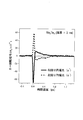
図2は、測定結果を示し、t=3nmのSb2Te3結晶薄膜で得られたカー回転(Kerr回転)信号の時間波形である。縦軸はカー回転角(Kerr回転角)Δθ、横軸は励起光と検出光の時間遅延τを示す。
σ-とσ+は、典型的な偏光状態に対応しており、σ-は回転角α=45度の場合の左回り円偏光の場合を示し、σ+は回転角α=135度の場合の右回り円偏光の場合を示す。時間遅延τがゼロのときに、σ-では、正のKerr回転角Δθを示し、一方、σ+では負のカー回転角(Kerr回転角)Δθを示す。
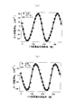
このカー回転角(Kerr回転角)Δθ信号をλ/4波長板回転角αに対してプロットしたものが、図3及び図4である。図3には、膜厚が、t=3nm(3QL)及びt=4nm(4QL)の場合を示し、図4には、膜厚が、t=5nm(5QL)及びt=6nm(6QL)の場合を示す。
ここで、●は実験値を示し、実線は、式(2)によるカーブフィッティング(https://ja.wikipedia.org/wiki/曲線あてはめ)の結果を示しており、また膜厚の単位は、Sb2Te3結晶を2次元層状物質と見たときの1層分(5原子層)として、1QL(quintuple layer)≒ 1nmと換算できる。
図3において、3QL、4QLの時には、回転角αが360度の範囲で2回だけ上下に凸となる信号を示すが、5QL、6QLの時には、回転角αが360度の範囲で2回以上、上下に凸となる信号を示すことが分かる。
段落0073で説明したとおり、このカーブフィッティングで得られたフィッティングパラメータである係数Cと係数Lのうち、係数Lの値を膜厚に対してプロットしたものが図5である。以上のとおりの試験例の結果得られた図5のデータにより、トポロジカル絶縁性を評価は次のように行われる。
図5を見ると、t=3QL(3nm)までは係数Lの値がほぼゼロであるが、t=4QL(4nm)以上になると係数Lの値が次第に大きくなり、t=10QL(10nm)まで非常に大きい値を示していることが分かる。
段落0074及び0086でも述べたように係数Lの値はバンド・ギャップの大きさに直接関係している物理量であるから、このグラフより、係数Lの値がほぼゼロであるt=3QL(3nm)までがバンド・ギャップが開いたエネルギーバンド構造を有する通常の絶縁体(Normal insulator: NI)であり、係数Lの値がゼロではなくなるt=4QL(4nm)からがバンド・ギャップが閉じたエネルギーバンド構造を有するトポロジカル絶縁体(Topological insulator: TI)であることが分かる。
この結果は、従来技術である角度分解型光電子分光法(ARPES)や走査トンネル顕微鏡(STM)の結果(例えば、非特許文献2)とほぼ一致しており、本発明の有効性を示している。なお、ここでは説明しないが、固体試料Bi2Te3についての試験例においても、同様の試験結果が得られている。
近年、トポロジカル絶縁体は、スピンデバイスの創成という観点で、非常に活発に基礎研究が進む一方、応用面での進展はあまり進んでいない。その原因に、応用する際に重要となるスピン電流はトポロジカル絶縁体の表面しか流れないこと、トポロジカル絶縁体になる物質系が主にカルコゲン半導体に限られていることなどが考えられる。
本発明により、非接触かつ、大気中・室温という簡易な条件下で、トポロジカル絶縁性の評価が可能になるため、新規のトポロジカル絶縁体の発見や、トポロジカル絶縁体の評価に有用である。
以上、本発明に係る固体のスピン特性からトポロジカル絶縁性を評価する方法及び装置を実施するための形態を実施例に基づいて説明したが、本発明はこのような実施例に限定されることなく、特許請求の範囲記載の技術的事項の範囲内で、いろいろな実施例があることは言うまでもない。
本発明に係る固体のスピン特性からトポロジカル絶縁性を評価する方法及び装置は、評価対象試料の膜厚を1nm~10mmの幅広い領域で可能とし、かつ、室温・大気中で評価を可能する。
そして、本発明に係る固体のスピン特性からトポロジカル絶縁性を評価する方法及び装置は、新規のトポロジカル絶縁体の発見や、トポロジカル絶縁体の評価に有用であり、トポロジカル絶縁体をはじめ、光記録や電気メモリに使用される相変化記録膜材料や、あるいは半導体などのあらゆる固体材料に対して適用可能である。
1 トポロジカル絶縁性を評価する装置
2 励起光(ポンプ光)
3 検出光(プローブ光)
4 フェムト秒パルスレーザー
5 分割装置
6 λ/4波長板
7 p偏光板
8 固体試料
11 固体試料で反射された検出光
12 ミラー
13 反射光
16 縦偏光
17 横偏光
18 偏光ビームスプリッター
21 縦偏光検出器
22 横偏光検出器
2 励起光(ポンプ光)
3 検出光(プローブ光)
4 フェムト秒パルスレーザー
5 分割装置
6 λ/4波長板
7 p偏光板
8 固体試料
11 固体試料で反射された検出光
12 ミラー
13 反射光
16 縦偏光
17 横偏光
18 偏光ビームスプリッター
21 縦偏光検出器
22 横偏光検出器
Claims (8)
- 励起光としてフェムト秒レーザーパルスを、λ/4波長板を回転させることで偏光状態を変化させトポロジカル絶縁体の固体試料である固体表面に照射し、固体表面に、逆ファラデー効果及び逆コットン・ムートン効果の両方又は一方を誘起せしめ、
該効果に基づいて生じるλ/4波長板回転角依存性を計測することにより、トポロジカル絶縁体等における固体表面に局在するスピン状態の評価と表面バンド状態の評価を行い、トポロジカル絶縁性を評価することを特徴とする固体のスピン特性からトポロジカル絶縁性を評価する方法。 - λ/4波長板回転角依存性は、コヒーレントスピン又は磁化Mとバンド構造を、フェムト秒レーザーパルスに対して時間遅延をつけた検出光であるプローブパルスを、不透明な固体試料である固体に照射し、その反射光によって磁気光学効果を利用してカー回転角を検出することにより評価することを特徴とする請求項1に記載の固体のスピン特性からトポロジカル絶縁性を評価する方法。
- カー回転角によって、検出フェムト秒レーザーパルス照射後、1ピコ秒以内の超高速時間に現れる逆ファラデー効果又は逆コットン・ムートン効果により過渡的に誘起された磁化Mに伴うスピンを検出することを特徴とする請求項2に記載の固体のスピン特性からトポロジカル絶縁性を評価する方法。
- λ/4波長板回転角依存性は、コヒーレントスピン又は磁化Mとバンド構造を、フェムト秒レーザーパルスに対して時間遅延をつけた検出光であるプローブパルスを、透明な固体試料である固体に照射し、該照射の透過光によって透過型のファラデー回転角を検出することにより、評価することを特徴とする請求項1に記載の固体のスピン特性からトポロジカル絶縁性を評価する方法。
- 逆ファラデー効果は、フェムト秒レーザーパルスを円偏光にして固体表面に照射することで誘起することを特徴とする請求項1~4のいずれかに記載の固体のスピン特性からトポロジカル絶縁性を評価する方法。
- 逆コットン・ムートン効果は、フェムト秒レーザーパルスを直線偏光にして固体表面に照射することで誘起することを特徴とする請求項1~4のいずれかに記載の固体のスピン特性からトポロジカル絶縁性を評価する方法。
- カー回転角又はファラデー回転角のλ/4波長板回転角α依存性を計測することによって、Lは逆コットン・ムートン効果によるカー回転を表す振幅とした場合に、Lsin4α成分の有無を測定することを特徴とする請求項2~5のいずれかに記載の固体のスピン特性からトポロジカル絶縁性を評価する方法。
- 励起光としてフェムト秒レーザーパルスを、λ/4波長板を回転させることで偏光状態を変化させてトポロジカル絶縁体における固体表面に照射し、固体表面に、逆ファラデー効果及び逆コットン・ムートン効果の両方又は一方を誘起せしめ、
該効果に基づいて生じるλ/4波長板回転角依存性を計測することにより、固体のスピン特性からトポロジカル絶縁性を評価する方法及び装置であって、
フェムト秒パルスレーザーからのビームを励起光と検出光の2つに分割する分割装置と、励起光の偏光状態を変化させるλ/4波長板と、検出光をp偏光させるp偏光板と、固体試料から反射された検出光をさらに反射するミラーと、ミラーからの反射光を縦偏光と横偏光に分波に分波する偏光ビームスプリッターと、縦偏光と横偏光をそれぞれ検出する光検出器と、を備えていることを特徴とするトポロジカル絶縁性を評価する装置。
Priority Applications (1)
| Application Number | Priority Date | Filing Date | Title |
|---|---|---|---|
| JP2018537039A JP6782026B2 (ja) | 2016-08-30 | 2017-07-28 | 固体のスピン特性からトポロジカル絶縁性を評価する方法及び装置 |
Applications Claiming Priority (2)
| Application Number | Priority Date | Filing Date | Title |
|---|---|---|---|
| JP2016167744 | 2016-08-30 | ||
| JP2016-167744 | 2016-08-30 |
Publications (1)
| Publication Number | Publication Date |
|---|---|
| WO2018042971A1 true WO2018042971A1 (ja) | 2018-03-08 |
Family
ID=61300729
Family Applications (1)
| Application Number | Title | Priority Date | Filing Date |
|---|---|---|---|
| PCT/JP2017/027375 Ceased WO2018042971A1 (ja) | 2016-08-30 | 2017-07-28 | 固体のスピン特性からトポロジカル絶縁性を評価する方法及び装置 |
Country Status (2)
| Country | Link |
|---|---|
| JP (1) | JP6782026B2 (ja) |
| WO (1) | WO2018042971A1 (ja) |
Cited By (5)
| Publication number | Priority date | Publication date | Assignee | Title |
|---|---|---|---|---|
| CN110208324A (zh) * | 2019-05-31 | 2019-09-06 | 福州大学 | 一种分离三维拓扑绝缘体Bi2Se3的不同线偏振张量引起的线偏振光致电流的方法 |
| CN110718608A (zh) * | 2019-10-18 | 2020-01-21 | 福州大学 | 调控锑化碲薄膜圆偏振相关光电流的方法 |
| CN112881773A (zh) * | 2021-01-18 | 2021-06-01 | 福州大学 | 测量拓扑绝缘体Bi2Te3中拉莫进动引起的磁致光电流的方法 |
| CN114199782A (zh) * | 2021-12-17 | 2022-03-18 | 福州大学 | 一种Sb2Te3拓扑表面态的圆偏振光电流调控方法 |
| CN116519142A (zh) * | 2023-06-19 | 2023-08-01 | 福州大学 | 一种用三维拓扑绝缘体薄膜进行偏振探测的方法 |
Citations (3)
| Publication number | Priority date | Publication date | Assignee | Title |
|---|---|---|---|---|
| JP2004226224A (ja) * | 2003-01-23 | 2004-08-12 | National Institute For Materials Science | 物質の光応答を測定する方法およびその装置 |
| JP2004335623A (ja) * | 2003-05-02 | 2004-11-25 | Japan Science & Technology Agency | 遷移金属又は希土類金属を固溶する透明強磁性アルカリ・カルコゲナイド化合物及びその強磁性特性の調整方法 |
| JP2016111219A (ja) * | 2014-12-08 | 2016-06-20 | 公立大学法人大阪府立大学 | 光伝導素子、テラヘルツ波発生装置、テラヘルツ波検出装置、テラヘルツ波発生方法およびテラヘルツ波検出方法 |
-
2017
- 2017-07-28 JP JP2018537039A patent/JP6782026B2/ja not_active Expired - Fee Related
- 2017-07-28 WO PCT/JP2017/027375 patent/WO2018042971A1/ja not_active Ceased
Patent Citations (3)
| Publication number | Priority date | Publication date | Assignee | Title |
|---|---|---|---|---|
| JP2004226224A (ja) * | 2003-01-23 | 2004-08-12 | National Institute For Materials Science | 物質の光応答を測定する方法およびその装置 |
| JP2004335623A (ja) * | 2003-05-02 | 2004-11-25 | Japan Science & Technology Agency | 遷移金属又は希土類金属を固溶する透明強磁性アルカリ・カルコゲナイド化合物及びその強磁性特性の調整方法 |
| JP2016111219A (ja) * | 2014-12-08 | 2016-06-20 | 公立大学法人大阪府立大学 | 光伝導素子、テラヘルツ波発生装置、テラヘルツ波検出装置、テラヘルツ波発生方法およびテラヘルツ波検出方法 |
Non-Patent Citations (6)
| Title |
|---|
| "Quantized Faraday and Kerr rotation and axion electrodynamics of a 3D topological insulator", SCIENCE, vol. 354, no. 6316, 2 December 2016 (2016-12-02), pages 1124 - 1127, XP055603814, DOI: 10.1126/science.aaf5541 * |
| DA HAIXIA: "Identification of trivial and nontrivial insulators: Enhanced lateral shift in topological insulator-based cavity", JOURNAL OF APPLIED PHYSICS, vol. 120, no. 125308, 29 September 2016 (2016-09-29), XP012212382, DOI: doi:10.1063/1.4963358 * |
| LI H ET AL: "Carrier density dependence of the magnetic properties in iron-doped Bi2Se3 topological insulator", JOURNAL OF APPLIED PHYSICS, vol. 113, no. 4, 30 January 2013 (2013-01-30), pages 043926-1 - 043926-5, XP012169730, DOI: doi:10.1063/1.4788834 * |
| MCLVER ET AL: "Control over topological insulator photocurrents with light polarization", NATURE NANOTECHNOLOGY, vol. 7, no. 2, 4 December 2011 (2011-12-04), pages 96 - 100, XP055210613, DOI: :10.1038/nnano.2011.214 * |
| OKADA ET AL: "Terahertz spectroscopy on Faraday and Kerr rotations in a quantum anomalous Hall state", NATURE COMMUNICATIONS, vol. 7, no. 12245, 20 July 2016 (2016-07-20), pages 1 - 6, XP055603823 * |
| YI ZHANG ET AL: "Crossover of the three-dimensional topological insulator Bi2Se3 to the two-dimensional limit", NATURE PHYSICS, vol. 6, no. 8, 13 June 2010 (2010-06-13), pages 584 - 588, XP055603833, DOI: doi:10.1038/nphys1689 * |
Cited By (8)
| Publication number | Priority date | Publication date | Assignee | Title |
|---|---|---|---|---|
| CN110208324A (zh) * | 2019-05-31 | 2019-09-06 | 福州大学 | 一种分离三维拓扑绝缘体Bi2Se3的不同线偏振张量引起的线偏振光致电流的方法 |
| CN110718608A (zh) * | 2019-10-18 | 2020-01-21 | 福州大学 | 调控锑化碲薄膜圆偏振相关光电流的方法 |
| CN110718608B (zh) * | 2019-10-18 | 2021-08-31 | 福州大学 | 调控锑化碲薄膜圆偏振相关光电流的方法 |
| CN112881773A (zh) * | 2021-01-18 | 2021-06-01 | 福州大学 | 测量拓扑绝缘体Bi2Te3中拉莫进动引起的磁致光电流的方法 |
| CN112881773B (zh) * | 2021-01-18 | 2022-05-10 | 福州大学 | 测量拓扑绝缘体Bi2Te3中拉莫进动引起的磁致光电流的方法 |
| CN114199782A (zh) * | 2021-12-17 | 2022-03-18 | 福州大学 | 一种Sb2Te3拓扑表面态的圆偏振光电流调控方法 |
| CN114199782B (zh) * | 2021-12-17 | 2023-08-18 | 福州大学 | 一种Sb2Te3拓扑表面态的圆偏振光电流调控方法 |
| CN116519142A (zh) * | 2023-06-19 | 2023-08-01 | 福州大学 | 一种用三维拓扑绝缘体薄膜进行偏振探测的方法 |
Also Published As
| Publication number | Publication date |
|---|---|
| JP6782026B2 (ja) | 2020-11-11 |
| JPWO2018042971A1 (ja) | 2019-07-11 |
Similar Documents
| Publication | Publication Date | Title |
|---|---|---|
| Temnov et al. | Multiphoton ionization in dielectrics: comparison of circular and linear polarization | |
| JP6782026B2 (ja) | 固体のスピン特性からトポロジカル絶縁性を評価する方法及び装置 | |
| Johnson et al. | Nanoscale depth-resolved coherent femtosecond motion in laser-excited bismuth | |
| Laman et al. | Ultrafast shift and injection currents observed in wurtzite semiconductors via emitted terahertz radiation | |
| McGilp | A review of optical second-harmonic and sum-frequency generation at surfaces and interfaces | |
| Zhu et al. | Effect of surface states on terahertz emission from the Bi2Se3 surface | |
| Cao et al. | Femtosecond laser driven precessing magnetic gratings | |
| JPS61223543A (ja) | 半導体の表面および表面下の特性を評価する方法ならびに装置 | |
| Aeschlimann et al. | Ultrafast momentum imaging of pseudospin-flip excitations in graphene | |
| Hashimshony et al. | Characterization of the electrical properties and thickness of thin epitaxial semiconductor layers by THz reflection spectroscopy | |
| Kiemle et al. | Ultrafast and local optoelectronic transport in topological insulators | |
| US10663773B2 (en) | Optical modulator using the spin hall effect in metals | |
| Henn et al. | Picosecond real-space imaging of electron spin diffusion in GaAs | |
| Tanksalvala et al. | Element-specific high-bandwidth ferromagnetic resonance spectroscopy with a coherent extreme-ultraviolet source | |
| Kudryashov et al. | Characteristic timescales of carrier dynamics in sulfur-hyperdoped silicon probed by femtosecond laser optical pump/THz probe pulses | |
| Lehmann et al. | Silver nanoparticles on graphite studied by femtosecond time-resolved multiphoton photoemission | |
| Hurley et al. | Time resolved imaging of carrier and thermal transport in silicon | |
| JPWO2006051766A1 (ja) | 光計測評価方法及び光計測評価装置 | |
| Kruglyak et al. | Ultrafast third-order optical nonlinearity of noble and transition metal thin films | |
| JP4558217B2 (ja) | 金属試料の特性を光学的に測定する方法及び装置 | |
| Janda et al. | Voigt effect-based wide-field magneto-optical microscope integrated in a pump-probe experimental setup | |
| Chen et al. | Measuring optical phonon dynamics in a bismuth thin film through a surface plasmon resonance | |
| Yuan et al. | Photoinduced spin precession in Fe/GaAs (001) heterostructure with low power excitation | |
| Beleckaitė et al. | Determination of the terahertz pulse emitting dipole orientation by terahertz emission measurements | |
| Lu et al. | Unveiling Giant Injection/Shift Current Ratio in Hybrid Quasi‐2D Perovskites |
Legal Events
| Date | Code | Title | Description |
|---|---|---|---|
| 121 | Ep: the epo has been informed by wipo that ep was designated in this application |
Ref document number: 17845980 Country of ref document: EP Kind code of ref document: A1 |
|
| ENP | Entry into the national phase |
Ref document number: 2018537039 Country of ref document: JP Kind code of ref document: A |
|
| NENP | Non-entry into the national phase |
Ref country code: DE |
|
| 122 | Ep: pct application non-entry in european phase |
Ref document number: 17845980 Country of ref document: EP Kind code of ref document: A1 |