WO2018037597A1 - 摩擦プーリの製造方法および摩擦プーリ - Google Patents
摩擦プーリの製造方法および摩擦プーリ Download PDFInfo
- Publication number
- WO2018037597A1 WO2018037597A1 PCT/JP2017/008973 JP2017008973W WO2018037597A1 WO 2018037597 A1 WO2018037597 A1 WO 2018037597A1 JP 2017008973 W JP2017008973 W JP 2017008973W WO 2018037597 A1 WO2018037597 A1 WO 2018037597A1
- Authority
- WO
- WIPO (PCT)
- Prior art keywords
- friction pulley
- rubber
- rubber ring
- outer peripheral
- rotating wheel
- Prior art date
- Legal status (The legal status is an assumption and is not a legal conclusion. Google has not performed a legal analysis and makes no representation as to the accuracy of the status listed.)
- Ceased
Links
Images


Classifications
-
- B—PERFORMING OPERATIONS; TRANSPORTING
- B29—WORKING OF PLASTICS; WORKING OF SUBSTANCES IN A PLASTIC STATE IN GENERAL
- B29C—SHAPING OR JOINING OF PLASTICS; SHAPING OF MATERIAL IN A PLASTIC STATE, NOT OTHERWISE PROVIDED FOR; AFTER-TREATMENT OF THE SHAPED PRODUCTS, e.g. REPAIRING
- B29C43/00—Compression moulding, i.e. applying external pressure to flow the moulding material; Apparatus therefor
- B29C43/02—Compression moulding, i.e. applying external pressure to flow the moulding material; Apparatus therefor of articles of definite length, i.e. discrete articles
- B29C43/18—Compression moulding, i.e. applying external pressure to flow the moulding material; Apparatus therefor of articles of definite length, i.e. discrete articles incorporating preformed parts or layers, e.g. compression moulding around inserts or for coating articles
-
- B—PERFORMING OPERATIONS; TRANSPORTING
- B29—WORKING OF PLASTICS; WORKING OF SUBSTANCES IN A PLASTIC STATE IN GENERAL
- B29C—SHAPING OR JOINING OF PLASTICS; SHAPING OF MATERIAL IN A PLASTIC STATE, NOT OTHERWISE PROVIDED FOR; AFTER-TREATMENT OF THE SHAPED PRODUCTS, e.g. REPAIRING
- B29C43/00—Compression moulding, i.e. applying external pressure to flow the moulding material; Apparatus therefor
- B29C43/32—Component parts, details or accessories; Auxiliary operations
- B29C43/36—Moulds for making articles of definite length, i.e. discrete articles
-
- F—MECHANICAL ENGINEERING; LIGHTING; HEATING; WEAPONS; BLASTING
- F16—ENGINEERING ELEMENTS AND UNITS; GENERAL MEASURES FOR PRODUCING AND MAINTAINING EFFECTIVE FUNCTIONING OF MACHINES OR INSTALLATIONS; THERMAL INSULATION IN GENERAL
- F16H—GEARING
- F16H55/00—Elements with teeth or friction surfaces for conveying motion; Worms, pulleys or sheaves for gearing mechanisms
- F16H55/32—Friction members
- F16H55/36—Pulleys
-
- F—MECHANICAL ENGINEERING; LIGHTING; HEATING; WEAPONS; BLASTING
- F16—ENGINEERING ELEMENTS AND UNITS; GENERAL MEASURES FOR PRODUCING AND MAINTAINING EFFECTIVE FUNCTIONING OF MACHINES OR INSTALLATIONS; THERMAL INSULATION IN GENERAL
- F16H—GEARING
- F16H55/00—Elements with teeth or friction surfaces for conveying motion; Worms, pulleys or sheaves for gearing mechanisms
- F16H55/32—Friction members
- F16H55/36—Pulleys
- F16H55/38—Means or measures for increasing adhesion
Definitions
- the present invention relates to a friction pulley manufacturing method and a friction pulley, and more particularly to a friction pulley used for power transmission in a vehicle or an industrial machine.
- a pulley or a belt is used as a power transmission mechanism for transmitting the power of a crankshaft to an auxiliary machine such as a water pump.
- the conventional power transmission mechanism has a configuration in which the crankshaft and all the auxiliary machines are connected by belts and pulleys, and power is transmitted from the crankshaft to all the auxiliary machines.
- Patent Document 1 a friction pulley having a pulley around which a belt attached to a crankshaft is wound, a support disk attached to a water pump, and a friction wheel made of an elastomer material installed on the outer periphery of the support disk. And a power transmission mechanism having an idle pulley that enables connection and separation between the pulley and the friction pulley.
- the idle pulley contacts the pulleys of the clan shaft and the water pump, and the crankshaft and the water pump are connected.
- the crankshaft and the water pump are separated from the pulleys. The connection between the two is cut off and the power transmission path can be selected.
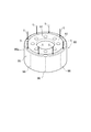
- FIG. 5 is a cross-sectional view along an axis x showing a schematic configuration of a conventional friction pulley 90.
- the friction pulley 90 includes a base 91 made of a plate-like member, and a rubber ring 95 attached integrally to the outer peripheral side (in the direction of arrow a) of the base 91.
- the base 91 is made of, for example, metal.
- the rubber ring 95 is made of a rubber material.
- the base body 91 is substantially L-shaped in cross section along the axis x, and is downward from the disk-shaped disk portion 92 centering on the axis x and the outer peripheral side (arrow a direction) end of the disk portion 92.
- a cylindrical portion 93 extending in the direction of arrow d and centering on the axis x is provided.
- a rubber ring 95 is integrally attached to a surface (hereinafter also referred to as “outer peripheral surface”) 93 a on the outer peripheral side (in the direction of arrow a) of the cylindrical portion 93.
- the rubber ring 95 is a ring-shaped member having a predetermined thickness from the outer peripheral surface 93a toward the outer peripheral side (arrow a direction) in a direction perpendicular to the axis x, and covers the outer peripheral surface 93a of the cylindrical portion 93. It is fixed integrally with the base 91.
- the rubber ring 95 is a portion that comes into contact (pressure contact) with or is separated from the idle pulley of the power transmission mechanism.
- the friction pulley 90 having such a configuration is used for driving a water pump, it is set on the assumption that a torque of about 3 Nm is transmitted. Therefore, in order to use the friction pulley 90 for a starter motor or the like that needs to transmit a high torque of 80 to 100 Nm, a rubber ring 95 made of a rubber material with higher strength is required.
- the present invention has been made in view of the above problems, and an object of the present invention is to provide a friction pulley manufacturing method and a friction pulley capable of transmitting a higher torque than conventional and having no molding defects.
- a method of manufacturing a friction pulley that transmits power to a target member in a state of being pressed against the target member to be rotated A first step of disposing an annular rotating ring integrated with an annular rubber ring in the cavity, the fixed mold, and a disk-shaped portion extending to the outer peripheral side about the axis of the rotating ring
- the rotating ring in which the rubber ring is integrated and the other rotating ring in which the rubber ring is integrated are connected to each other. It has the 4th step of connecting and fixing along the direction of the axis in the state of contact.
- the rubber fabric is characterized in that a cross-sectional shape in a cross section along the axis is a square shape or a rectangular shape close to a square shape.
- a friction pulley that transmits power to the target member in a state of being pressed against the rotating target member, and a main body portion that is a disk-shaped portion that extends to the outer peripheral side about the axis, and the main body
- One annular rotating wheel having a flange portion which is a cylindrical portion centering on an axis extending from the outer peripheral end portion to the outside, and the other annular portion having the main body portion and the flange portion
- the other rotating wheel integrated with the rubber ring is connected and fixed along the direction of the axis in a state where the rubber rings are in contact with each other.
- the friction pulley is manufactured by compression molding, it is possible to provide a friction pulley manufacturing method and a friction pulley that can transmit a higher torque than before and that do not have molding defects.
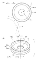
- FIG. 1 (A) is a side view of a friction pulley
- FIG.1 (B) is a rough-line perspective view of a friction pulley.
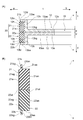
- FIG. 2A is a cross-sectional view along the axis showing the schematic configuration of the friction pulley according to the embodiment of the present invention
- FIG. 2A is a cross-sectional view along the axis of the friction pulley 1
- FIG. ) Is an enlarged cross-sectional view of the rubber ring 20.
- FIG. 1 is a diagram showing a schematic configuration of a friction pulley 1 according to an embodiment of the present invention.
- FIG. 1A is a side view of the friction pulley 1
- FIG. 1B is a schematic perspective view of the friction pulley 1.
- FIG. 2 is a diagram showing a schematic configuration of the friction pulley 1 according to the embodiment of the present invention.
- 2A is a cross-sectional view of the friction pulley 1 along the axis
- FIG. 2B is an enlarged cross-sectional view of the rubber ring 20.
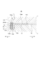
- FIG. 3 is a partially enlarged sectional view for explaining the manufacturing process of the friction pulley 1 according to the embodiment of the present invention.
- FIG. 4 is a flowchart for explaining a manufacturing process of the friction pulley 1 according to the embodiment of the present invention.
- the outer peripheral side is defined as a direction (arrow a direction) that is away from the axis x in a direction perpendicular to the direction of the axis x.
- the inner peripheral side is a direction (arrow a direction) approaching the axis x in a direction perpendicular to the axis x direction (hereinafter also referred to as “radial direction”).
- the external side is a side away from the internal combustion engine, and is defined as an upward direction (arrow c direction) along the axis x direction.
- the inner side is the side closer to the internal combustion engine, and is defined as the lower direction (arrow d direction) in the axis x direction.
- the friction pulley 1 is a target member (hereinafter also referred to as a “rotating member”) R that rotates on the outer periphery thereof. Used to transmit power in a pressed state.
- the friction pulley 1 is pressed against a pulley as a rotating member R attached to a crankshaft, or is pressed against an outer peripheral surface of a timing belt as a rotating member R wound around the pulley.
- the power of the motor is transmitted to the crankshaft and used to start the internal combustion engine.
- the friction pulley 1 may be used for transmitting the power of the crankshaft to an auxiliary machine such as a water pump or for transmitting the power between the auxiliary machine and the auxiliary machine.
- the friction pulley 1 is between a power transmission state in which the friction pulley 1 is in pressure contact with the rotating member R and can transmit power, and a non-power transmission state in which the friction pulley 1 is not in pressure contact with the rotating member R and does not transmit power.
- a biasing member such as a driving device or a spring.
- the friction pulley 1 includes a pair of rotating wheels 12 and 13 each having an annular groove 11 that is recessed by a predetermined depth toward the inner peripheral side (in the direction of arrow a), And an annular rubber ring 20 that is integrally fixed in a state of being accommodated in the groove 11 of the rotary wheels 12 and 13.
- the rotary wheels 12 and 13 are integrally fixed in a state of facing each other along a longitudinal direction perpendicular to the axis x direction.
- the rotating wheels 12 and 13 have the same shape as a mirror surface object, and both have a common configuration. Therefore, here, the configuration of one rotating wheel 12 will be mainly described, and the configuration of the other rotating wheel 13 will be described as necessary.
- the rotating wheel 12 is made of metal or resin, and includes a main body portion 12a and a flange portion 12b.
- the main body 12a of the rotating wheel 12 is a disk-shaped portion having a predetermined width w in the axis x direction and extending toward the outer peripheral side (arrow a direction) in the radial direction (arrow ab direction) with the axis x as the center. .
- the main body 12a has a through-hole 16 extending in the axis x direction at the center.
- the flange portion 12b of the rotating wheel 12 is a cylindrical portion centering on the axis line x extending from the end portion on the outer peripheral side (arrow a direction) of the main body portion 12a to the outside side (arrow c).
- the flange portion 12b has a flat outer peripheral surface 12bg along the axis x direction.
- the flange portion 12b has an annular convex ring portion 12bs that slightly protrudes from the outermost end on the outer side (in the arrow c direction) toward the outer peripheral side (in the arrow a direction).
- the convex ring portion 12bs has an inner side surface 12bi perpendicular to the axis x direction and an outer peripheral end surface 12bt along the axis x direction on the outer peripheral side (arrow a direction) of the convex ring portion 12bs.
- the rotating wheel 13 also includes a main body portion 13a, a flange portion 13b, and a convex ring portion 13bs, similarly to the rotating wheel 12.
- a concave portion 12h for forming the groove 11 is defined by the inner surface 12bi of the convex ring portion 12bs of the flange portion 12b and the outer peripheral surface 12bg of the flange portion 12b.
- a recess 13h for forming the groove 11 is defined by the inner surface 13bi of the convex ring portion 13bs of the flange portion 13b and the outer peripheral surface 13bg of the flange portion 13b.
- the rotating wheels 12 and 13 are integrally fixed by bolts and nuts (not shown) in a state where the flange portions 12b and 13b are separated from each other and the main body portions 12a and 13a are in close contact with each other. That is, the rotating wheels 12 and 13 have a configuration that can be integrated and divided by bolts and nuts. In fixing the rotating wheels 12 and 13 to each other, not only bolts and nuts but also various fixing means such as locking with pins or the like can be used.
- the concave surface 12h defined by the inner surface 12bi of the convex ring portion 12bs of the flange portion 12b, the outer peripheral surface 12bg of the flange portion 12b, the inner side surface 13bi of the convex ring portion 13bs of the flange portion 13b, and the flange portion 13b.
- the concave space of the groove 11 is defined by spatially connecting the concave portion 13h defined by the outer peripheral surface 13bg.
- the rubber ring 20 is formed of a rubber material, and various rubber materials can be used, and a rubber material having physical properties according to requirements is selected.
- examples of the rubber material of the rubber ring 20 include nitrile rubber (NBR), hydrogenated nitrile rubber (H-NBR), ethylene propylene rubber (EPDM), styrene butadiene rubber (SBR), natural rubber (NR), and urethane rubber. It is.
- the rubber ring 20 is formed between a semi-rubber ring portion 21 as a rubber ring that is integrally fixed in a state of being accommodated in the concave portion 12h of the rotating wheel 12, and a concave portion 13h of the rotating wheel 13. It is composed of a semi-rubber ring portion 22 as a rubber ring that is integrally fixed in the accommodated state, and is integrally formed in a state where the semi-rubber ring portion 21 and the semi-rubber ring portion 22 are in contact with each other along the axis x direction. It is composed.
- the semi-rubber ring portion 21 has a shape that covers both the flange portion 12b and the convex ring portion 12bs of the rotating wheel 12 from the outer peripheral side (arrow a direction). Specifically, the semi-rubber ring portion 21 is further externally formed from an annular main rubber portion 21a having a rectangular cross section with respect to the axis x, and an outermost end surface on the outer side (arrow c direction) of the main rubber portion 21a. An annular sub-rubber portion 21b having a thin plate-like cross-section projecting slightly in the direction of arrow c is provided.
- the semi-rubber ring portion 22 has the same configuration as the semi-rubber ring portion 21 and includes a main rubber portion 22a and a sub rubber portion 22b.
- the main rubber portion 21a of the semi-rubber ring portion 21 includes an inner peripheral surface 21an that is a surface on the inner peripheral side (arrow b direction), an outer side surface 21as that is an outer (arrow c direction) surface, and an inner side (arrow d direction). It has an inner side surface 21at which is a surface and an outer peripheral surface 21ag which is a surface on the outer peripheral side (in the direction of arrow a).
- the inner peripheral surface 21an is a flat surface that is integrally connected to the outer peripheral surface 12bg of the flange portion 12b of the rotating wheel 12.
- the outer side surface 21as is a flat surface that is integrally connected to the inner side surface 12bi of the convex ring portion 12bs of the rotating wheel 12.
- the inner side surface 21at is a flat surface that comes into contact with the inner side surface 22at of the semi-rubber ring portion 22, and is flush with the inner side surface 12as of the main body portion 12a of the rotating wheel 12.
- the outer peripheral surface 21ag is a portion exposed in the friction pulley 1 and is a flat surface pressed against the rotating member R.
- the secondary rubber portion 21b of the semi-rubber ring portion 21 has an inner peripheral surface 21bn and an outer peripheral surface 21bg.
- the inner peripheral surface 21bn is a flat surface that is integrally connected to the outer peripheral end surface 12bt of the convex ring portion 12bs of the rotating wheel 12.
- the outer peripheral surface 21 bg is a flat surface that faces away from the inner peripheral surface 21 bn and is exposed in the friction pulley 1.
- the outer peripheral surface 21bg of the secondary rubber portion 21b is in a position recessed toward the inner peripheral side (in the direction of arrow b) with respect to the outer peripheral surface 21ag of the main rubber portion 21a, and is usually a surface that is not pressed against the rotating member R. is there.
- the semi-rubber ring portion 22 has a shape that covers both the flange portion 13b and the convex ring portion 13bs of the rotating wheel 13 from the outer peripheral side (arrow a direction).
- the main rubber portion 21a of the semi-rubber ring portion 21 and the main rubber portion 22a of the semi-rubber ring portion 22 are integrally fixed with bolts and nuts in a state where the main body portions 12a and 13a of the rotating wheels 12 and 13 are in close contact with each other. In doing so, the inner side surface 21at of the main rubber portion 21a and the inner side surface 22at of the main rubber portion 22a are brought into contact with each other to be integrated. As a result, the rubber ring 20 in which the semi-rubber ring portions 21 and 22 are combined is configured. However, the inner side surface 21at of the main rubber portion 21a and the inner side surface 22at of the main rubber portion 22a are not bonded.
- the rotating wheel 12 is placed in the cavity 50 of the fixed mold KL of the compression molding machine 40 (first step SP1).
- the outer peripheral surface 12bg of the flange portion 12b of the rotating wheel 12 disposed in the cavity 50, the inner surface 12bi of the convex ring portion 12bs, and the outer peripheral end surface 12bt are not in contact with the inner wall 51 of the cavity 50 and are exposed. is doing.
- the wall portion of the inner wall 51 that faces the outer peripheral end surface 12bt of the convex ring portion 12bs is positioned closer to the inner peripheral side (in the direction of the arrow b) than the portion that faces the outer peripheral surface 12bg of the flange portion 12b. Therefore, while the interval between the inner wall 51 and the outer peripheral surface 12bg of the flange portion 12b is formed wide, the interval between the inner wall 51 and the outer peripheral end surface 12bt of the convex ring portion 12bs is formed narrow.
- the rubber cloth 20raw is disposed so as to come into contact with the outer peripheral surface 12bg of the flange portion 12b and the inner side surface 12bi of the convex ring portion 12bs.
- the rubber fabric 20raw used here preferably has a square cross-section in the cross section along the axis x or a rectangular shape close to a square shape.
- the rubber mold 20raw is compressed between the movable mold KU and the fixed mold KL by pushing down the movable mold KU of the compression molding machine toward the fixed mold KL. Is pressed and cured, so that the semi-rubber ring portion 21 is integrated with the outer peripheral surface 12bg of the flange portion 12b of the rotating wheel 12 (third step SP3).
- the rotating wheel 12 with the semi-rubber ring portion 21 fixed integrally in this manner is taken out from the stationary mold KL.
- the semi-rubber ring portions 21, 22 are fixed to each other, and the rotary ring 12, to which the semi-rubber ring portion 21 is fixed integrally with the compression molding machine 40.
- the main body portions 12a and 13a are in contact with each other along the direction of the axis line x by bolts and nuts and fixed together (fourth step SP4).
- the inner side surface 21at of the semi-rubber ring portion 21 and the inner side surface 22at of the semi-rubber ring portion 22 are merely in contact and are not bonded, but the main body portions 12a, 13a are bolts and Since the nuts are integrally fixed, the rubber ring 20 is formed as if it were integrated.
- the friction pulley 1 that is integrally fixed in a state where the rubber ring 20 is accommodated in the groove 11 of the rotating wheels 12 and 13.
- the friction pulley 1 is manufactured by compression molding using an annular lump of rubber fabric 20raw trough, so that a plurality of inlets are provided in the mold cavity as in the prior art (see FIG. 5).
- a rubber material from ij it is possible to prevent the occurrence of welds (unsatisfactory fusion) that cause early failure.
- the rubber ring 20 is configured by integrating the semi-rubber ring portion 21 and the semi-rubber ring portion 22 that are vertically divided in the direction of the axis x with each other being overlapped with each other.
- the rubber ring 20 is formed by contacting the semi-rubber ring portion 21 and the semi-rubber ring portion 22 which are short in the direction of the axis line x or have a rectangular cross section close to the cross section square to form the rubber ring 20. This can be avoided in advance, and the occurrence of welds can be prevented.
- the friction pulley 1 has the semi-rubber ring portion 21 and the semi-rubber ring portion 22 integrally fixed to the rotating wheel 12 and the rotating wheel 13 by compression molding, so that compared to the conventional injection molding.
- the molding pressure during compression molding can be lowered.
- the possibility that the rotating wheels 12 and 13 are deformed by the molding pressure can be greatly reduced, it is possible to prevent variation in the dimensional accuracy of the outer peripheral surface of the rubber ring 20.
- the friction pulley 1 is integrally formed in a state where the rubber ring 20 is accommodated in the concave space of the groove 11 formed by the convex ring portions 12bs and 13bs of the flange portions 12b and 13b of the rotating wheels 12 and 13. .
- the friction pulley 1 prevents the rubber ring 20 from being displaced in the direction of the axis line x by the convex ring portions 12bs and 13bs at the time of the pressure contact with the rotating member R that transmits power, and is stable with respect to the rotating member R. Power can be transmitted.
- the auxiliary rubber portions 21 b and 22 b of the semi-rubber ring portions 21 and 22 in the rubber ring 20 cover the outer peripheral end surfaces 12 bt and 13 bt of the convex ring portions 12 bs and 13 bs of the rotating wheels 12 and 13.
- the rotating member R immediately comes into contact with the convex ring portions 12bs and 13bs of the rotating wheels 12 and 13 in the friction pulley 1. Can be avoided, and damage to the rotating member R and the friction pulley 1 can be prevented.
- the present invention is not limited thereto. Instead, at least only the main rubber portions 21a and 22a may be provided.
- the rubber ring 20 is configured by the two semi-rubber ring portions 21 and 22 has been described.
- the present invention is not limited to this, and three or more rubber ring portions are provided. You may make it comprise by making mutually contact
Landscapes
- Engineering & Computer Science (AREA)
- General Engineering & Computer Science (AREA)
- Mechanical Engineering (AREA)
- Pulleys (AREA)
Abstract
従来よりも高いトルクを伝達可能でかつ成形不良の存在しない摩擦プーリの製造方法および摩擦プーリを提供するようにする。 回転する対象部材に圧接された状態で当該対象部材に動力を伝達する摩擦プーリの製造方法であって、所定の圧縮成形機の固定側金型に環状のゴム環と一体化される環状の回転輪を配置する第1ステップと、固定側金型と、回転輪の軸線に対して外周側に広がった円盤状のフランジ部との間に形成された環状の凹部領域にゴム環を構成する一塊の環状のゴム生地を配置する第2ステップと、圧縮成形機の可動側金型と固定側金型との間でゴム生地を圧縮し、回転輪のフランジ部の外周面にゴム環を一体化させる第3ステップと、を有する。
Description
本発明は、摩擦プーリの製造方法および摩擦プーリに関し、特に、車両や産業機械において動力の伝達のために用いられる摩擦プーリに関する。
従来、車両の内燃機関において、クランクシャフトの動力をウォータポンプ等の補機に伝達するための動力伝達機構としては、プーリやベルトが用いられている。従来の動力伝達機構は、クランクシャフトと全ての補機がベルトおよびプーリによって連結されており、クランクシャフトから全ての補機に動力が伝達される構成を有している。
このため、このような動力伝達機構を備えた内燃機関においては、クランクシャフトと全ての補機がベルトおよびプーリによって連結されているため、内燃機関により発生したエネルギーの損失が大きくなっていた。これに対して、近年、クランクシャフトと補機との間の連結および切断を選択可能にする構成を有する動力伝達機構が提案されている(例えば、特許文献1、2参照。)。
特許文献1においては、クランクシャフトに取り付けられたベルトが巻き掛けられたプーリと、ウォータポンプに取り付けられた支持ディスクとこの支持ディスクの外周に設置されたエラストマー材料からなる摩擦輪とを有する摩擦プーリと、これらプーリおよび摩擦プーリ間を連結および分離可能にするアイドルプーリとを有する動力伝達機構が開示されている。
この従来の動力伝達機構においては、アイドルプーリが、クランシャフトおよびウォータポンプの各プーリに接触して、クランクシャフトとウォータポンプとが連結され、また、各プーリから離間して、クランクシャフトとウォータポンプとの間の連結が切断され、動力伝達路の選択が可能となっている。
次に、摩擦プーリの具体的構成について説明する。図5は、従来の摩擦プーリ90の概略構成を示す軸線xに沿う断面図である。摩擦プーリ90は、板状部材からなる基体91と、当該基体91の外周側(矢印a方向)に一体に取り付けられたゴム環95とを備えている。基体91は、例えば金属から形成されている。ゴム環95は、ゴム材料から形成されている。
基体91は、軸線xに沿う断面の形状が略L字状であり、軸線xを中心とする円盤状の円盤部92と、当該円盤部92の外周側(矢印a方向)の端部から下方(矢印d方向)に向かって延び、軸線xを中心とする円筒状の円筒部93とを備えている。円筒部93の外周側(矢印a方向)の面(以下、これを「外周面」ともいう。)93aには、ゴム環95が一体に取り付けられている。
ゴム環95は、外周面93aから軸線xとは垂直な方向における外周側(矢印a方向)へ向かって所定の厚さを有するリング状部材であり、円筒部93の外周面93aを覆うように基体91と一体に固定されている。このゴム環95は、動力伝達機構のアイドルプーリと当接(圧接)または離間される部分となる。
このような構成の摩擦プーリ90は、ウォータポンプの駆動用であるため、3Nm程度のトルクを伝達することを前提に設定されている。したがって、80~100Nmの高いトルクの伝達が必要なスタータモータ等に摩擦プーリ90を用いるには、更に高強度のゴム材料からなるゴム環95が要求される。
しかしながら、上述した構成の摩擦プーリ90のゴム環95として、更に高強度のゴム材料を用いる場合、ゴム材料の粘土が上がるので、加硫成形時のゴム流動性が悪化してしまう。
このため、図6に示すように、図中矢印で示す複数の注入口ijから図示しない金型のキャビティにゴム環95のゴム材料を強制注入する注入成形の場合、注入口ijと注入口ijとのほぼ中間位置にゴム材料の合流部分となるウェルド(融合不良)96が成形不良として発生してしまう。ゴム環95にウェルド96の成形不良が発生した場合、摩擦プーリ90の使用時、このウェルド96を起点として亀裂が発生し、その後に更に亀裂が進展し、早期にゴム破損を生じていた。
また、注入成形の場合、ゴム流動性の悪いゴム材料をキャビティに流し込んでいるため、非常に大きな成形圧力が必要となる。したがって、大きな成形圧力により基体91が変形した場合、機能的に重要なゴム環95の外周面95aの外径に振れ等が生じて寸法精度にばらつきが生じていた。
本発明は、上記の課題に鑑みなされたものであり、その目的は、従来よりも高いトルクを伝達可能でかつ成形不良の存在しない摩擦プーリの製造方法および摩擦プーリを提供することである。
上記目的を達成するために、本発明においては、回転する対象部材に圧接された状態で当該対象部材に動力を伝達する摩擦プーリの製造方法であって、所定の圧縮成形機における固定側金型のキャビティに環状のゴム環と一体化される環状の回転輪を配置する第1ステップと、前記固定側金型と、前記回転輪の軸線を中心として外周側に拡がった円盤状の部分である本体部の外周側の端部から外部側へ拡がる軸線を中心とした円筒状の部分であるフランジ部との間に形成された環状の凹部領域に一塊の環状のゴム生地を配置する第2ステップと、前記圧縮成形機の可動側金型と前記固定側金型との間で前記ゴム生地を圧縮成形し、前記回転輪の前記フランジ部の外周面に対して前記ゴム環を一体化させる第3ステップと、を有することを特徴とする。
本発明の一態様に係る摩擦プーリの製造方法において、前記ゴム環が一体化された前記回転輪と、前記ゴム環が一体化された他の前記回転輪とを、互いの前記ゴム環同士を当接した状態で前記軸線の方向に沿って接続して固定する第4ステップを有することを特徴とする。
本発明の一態様に係る摩擦プーリの製造方法において、前記ゴム生地は、前記軸線に沿った断面における断面形状が正方形状、または、正方形状に近い矩形状であることを特徴とする。
本発明においては、回転する対象部材に圧接された状態で当該対象部材に動力を伝達する摩擦プーリであって、軸線を中心として外周側に拡がった円盤状の部分である本体部と、当該本体部の外周側の端部から外部側へ拡がる軸線を中心とした円筒状の部分であるフランジ部とを有する環状の一方の回転輪と、前記本体部と前記フランジ部とを有する環状の他方の回転輪と、前記フランジ部の外周面に対して一塊の環状のゴム生地が圧縮成形により一体化されてなる環状のゴム環とを備え、前記ゴム環が一体化された前記一方の回転輪と、前記ゴム環が一体化された前記他方の回転輪とが、互いのゴム環同士を当接した状態で前記軸線の方向に沿って接続して固定されていることを特徴とする。
本発明によれば、圧縮成形により摩擦プーリを製造するので、従来よりも高いトルクを伝達可能でかつ成形不良の存在しない摩擦プーリの製造方法および摩擦プーリを提供することができる。
以下、本発明の実施の形態について図面を参照し説明する。
図1は、本発明の実施の形態に係る摩擦プーリ1の概略構成を示す図である。特に、図1(A)は、摩擦プーリ1の側面図であり、図1(B)は、摩擦プーリ1の略線的斜視図である。図2は、本発明の実施の形態に係る摩擦プーリ1の概略構成を示す図である。特に、図2(A)は摩擦プーリ1の軸線に沿った断面における断面図であり、図2(B)はゴム環20の拡大断面図である。図3は、本発明の実施の形態に係る摩擦プーリ1の製造工程の説明に供する部分拡大断面図である。図4は、本発明の実施の形態に係る摩擦プーリ1の製造工程の説明に供するフローチャートである。
以下、説明の便宜上、図1乃至図3において、外周側とは、軸線x方向と垂直な方向において軸線xから離れる方向(矢印a方向)とする。また、内周側とは軸線x方向と垂直な方向(以下、「径方向」ともいう。)において軸線xに近づく方向(矢印a方向)とする。さらに、外部側とは、内燃機関から離間する側であり、軸線x方向に沿って上側方向(矢印c方向)とする。内部側とは、内燃機関に近づく側であり、軸線x方向において下側方向(矢印d方向)とする。
<摩擦プーリの構成>
本発明の実施の形態において、図1(A)および(B)に示すように、摩擦プーリ1は、その外周において、回転する対象部材(以下、これを「回転部材」ともいう。)Rに圧接された状態で動力を伝達するために用いられる。
本発明の実施の形態において、図1(A)および(B)に示すように、摩擦プーリ1は、その外周において、回転する対象部材(以下、これを「回転部材」ともいう。)Rに圧接された状態で動力を伝達するために用いられる。
摩擦プーリ1は、例えば車両の内燃機関において、クランクシャフトに取り付けられた回転部材Rとしてのプーリに直接、または、このプーリに巻き掛けられた回転部材Rとしてのタイミングベルトに外周面において圧接されてモータの動力をクランクシャフトに伝達し、内燃機関を始動するために用いられる。
ただし、摩擦プーリ1は、クランクシャフトの動力をウォータポンプ等の補機に伝達するために、または、補機と補機との間の動力の伝達のために用いられてもよい。また、摩擦プーリ1は、回転部材Rに圧接されて動力を伝達可能な位置にある動力伝達状態と、回転部材Rに圧接されておらず動力を伝達しない位置にある非動力伝達状態との間で、駆動装置やバネ等の付勢部材を用いて選択移動可能に取り付けられていてもよい。
図2(A)に示すように、摩擦プーリ1は、内周側(矢印a方向)へ所定深さだけ凹む環状の溝11が外周に形成された1対の回転輪12、13と、当該回転輪12、13の溝11内に収容された状態で一体に固定された環状のゴム環20とを備えている。
回転輪12、13は、軸線x方向とは垂直な長手方向に沿って互いに向かい合った状態で一体に固定されている。回転輪12、13は、互いに鏡面対象となる同一形状を有しており、双方ともに共通の構成を有している。したがって、ここでは、一方の回転輪12の構成について主に説明し、他方の回転輪13の構成については必要に応じて説明する。
回転輪12は、金属または樹脂から形成されており、本体部12aおよびフランジ部12bを備えている。回転輪12の本体部12aは、軸線x方向に所定の幅wを有し、当該軸線xを中心として径方向(矢印ab方向)の外周側(矢印a方向)へ拡がる円盤状の部分である。本体部12aは、中心部分に軸線x方向に延びる貫通孔16を有している。
回転輪12のフランジ部12bは、本体部12aの外周側(矢印a方向)の端部から外部側(矢印c)へ拡がる軸線xを中心とした円筒状部分である。フランジ部12bは、軸線x方向に沿って平坦な外周面12bgを有している。
また、フランジ部12bは、その外部側(矢印c方向)の最外端から更に外周側(矢印a方向)へ向かって僅かに突出した環状の凸環部12bsを有している。凸環部12bsは、軸線x方向とは垂直な内側面12bi、および、当該凸環部12bsの外周側(矢印a方向)において軸線x方向に沿った外周端面12btを有している。なお、回転輪13においても、回転輪12と同様に、本体部13a、フランジ部13bおよび凸環部13bsを備えている。
回転輪12においては、フランジ部12bの凸環部12bsの内側面12biと、フランジ部12bの外周面12bgとにより溝11を形成するための凹部12hが画成される。同様に、回転輪13においても、フランジ部13bの凸環部13bsの内側面13biと、フランジ部13bの外周面13bgとにより溝11を形成するための凹部13hが画成される。
回転輪12、13は、互いのフランジ部12b、13bが離間し、かつ、本体部12a、13a同士が密着した状態で図示しないボルトおよびナットにより一体に固定されている。すなわち、回転輪12、13は、ボルトおよびナットにより一体化可能かつ分割可能な構成を有している。なお、回転輪12、13同士を固定するに際し、ボルトおよびナットに限らず、ピン等による係止等の種々の固定手段を用いることができる。
この場合、回転輪12、13が一体化された状態において、フランジ部12b、13bの凸環部12bs、13bsの互いに対向する内側面12bi、13biと、フランジ部12b、13bの外周面12bg、13bgとによって囲まれた凹空間が環状の溝11となる。
すなわち、フランジ部12bの凸環部12bsの内側面12biと、フランジ部12bの外周面12bgとにより画成された凹部12hと、フランジ部13bの凸環部13bsの内側面13biと、フランジ部13bの外周面13bgとにより画成された凹部13hとが空間的に繋がったことにより溝11の凹空間が画成される。
ゴム環20は、ゴム材料から形成されており、種々のゴム材料を用いることができ、要求に応じた物性を有するゴム材料が選択される。ゴム環20のゴム材料としては、例えば、ニトリルゴム(NBR)、水素添加ニトリルゴム(H-NBR)、エチレンプロピレンゴム(EPDM)、スチレンブタジエンゴム(SBR)、天然ゴム(NR)やウレタンゴム等である。
図2(B)に示すように、ゴム環20は、回転輪12の凹部12hに収容された状態で一体に固定されるゴム環としての半ゴム環部21と、回転輪13の凹部13hに収容された状態で一体に固定されるゴム環としての半ゴム環部22とからなり、半ゴム環部21と半ゴム環部22とが軸線x方向に沿って当接された状態で一体に構成されるものである。
半ゴム環部21は、回転輪12のフランジ部12bおよび凸環部12bsの双方を外周側(矢印a方向)から覆うような形状を有している。具体的には、半ゴム環部21は、軸線xに対して断面矩形状の環状の主ゴム部21a、および、当該主ゴム部21aの外部側(矢印c方向)の最外端面から更に外部(矢印c方向)へ僅かに突出した断面薄板状の環状の副ゴム部21bを備えている。半ゴム環部22についても、半ゴム環部21と同様の構成を有し、主ゴム部22aおよび副ゴム部22bを備えている。
半ゴム環部21の主ゴム部21aは、内周側(矢印b方向)の面である内周面21an、外側(矢印c方向)の面である外側側面21as、内側(矢印d方向)の面である内側側面21at、および、外周側(矢印a方向)の面である外周面21agを有している。
内周面21anは、回転輪12のフランジ部12bの外周面12bgと一体に接続される平坦な面である。外側側面21asは、回転輪12の凸環部12bsの内側面12biと一体に接続される平坦な面である。内側側面21atは、半ゴム環部22の内側側面22atと当接される平坦な面であり、回転輪12の本体部12aの内側面12asと面一である。外周面21agは、摩擦プーリ1において露出する部分であり、回転部材Rに圧接される平坦な面である。
半ゴム環部21の副ゴム部21bは、内周面21bnおよび外周面21bgを有している。内周面21bnは、回転輪12の凸環部12bsの外周端面12btと一体に接続される平坦な面である。外周面21bgは、内周面21bnと背向し、摩擦プーリ1において露出する平坦な面である。
副ゴム部21bの外周面21bgは、主ゴム部21aの外周面21agよりも内周側(矢印b方向)に凹んだ位置にあり、通常においては回転部材Rに圧接されることのない面である。因みに、半ゴム環部22についても、同様に、回転輪13のフランジ部13bおよび凸環部13bsの双方を外周側(矢印a方向)から覆うような形状を有している。
ここで、半ゴム環部21の主ゴム部21aおよび半ゴム環部22の主ゴム部22aは、回転輪12、13の本体部12a、13a同士が密着した状態でボルトおよびナットにより一体に固定される際、主ゴム部21aの内側側面21atと、主ゴム部22aの内側側面22atとが互いに当接されて一体化される。この結果、半ゴム環部21、22が合体されたゴム環20が構成される。ただし、主ゴム部21aの内側側面21atと、主ゴム部22aの内側側面22atとは接着されている訳ではない。
<摩擦プーリの製造方法>
上述したような構成の摩擦プーリ1を製造する製造方法においては、回転輪12の凹部12hに半ゴム環部21を一体に固定する成形工程、および、その後に、半ゴム環部21が一体化された一方の回転輪12と、半ゴム環部22が一体化された他方の回転輪13とを一体に取り付けて固定する組立工程に分けて説明する。
上述したような構成の摩擦プーリ1を製造する製造方法においては、回転輪12の凹部12hに半ゴム環部21を一体に固定する成形工程、および、その後に、半ゴム環部21が一体化された一方の回転輪12と、半ゴム環部22が一体化された他方の回転輪13とを一体に取り付けて固定する組立工程に分けて説明する。
図3および図4に示すように、最初に、圧縮成形機40の固定側金型KLのキャビティ50に回転輪12を配置する(第1ステップSP1)。この場合、キャビティ50に配置された回転輪12のフランジ部12bの外周面12bg、凸環部12bsの内側面12bi、および、外周端面12btについては、キャビティ50の内壁51と接触しておらず露出している。
ただし、内壁51のうち、凸環部12bsの外周端面12btと対向する壁部分については、フランジ部12bの外周面12bgと対向する部分よりも内周側(矢印b方向)に位置されている。したがって、内壁51とフランジ部12bの外周面12bgとの間隔は広く形成されているのに対し、内壁51と凸環部12bsの外周端面12btとの間隔は狭く形成されている。
固定側金型KLのキャビティ50において、回転輪12の軸線xに対して外周側へ拡がった円盤状のフランジ部12bの外周面12bg、および、凸環部12bsの内側面12biとの間に形成された環状の凹部領域に環状の一塊のゴム生地20raw を配置する(第2ステップSP2)。
この際、ゴム生地20raw は、フランジ部12bの外周面12bg、および、凸環部12bsの内側面12biと接触するように配置される。なお、ここで用いられるゴム生地20rawは、軸線xに沿った断面における断面形状が正方形状、または、正方形状に近い矩形状であることが望ましい。
その後、圧縮成形機の可動側金型KUを固定側金型KLに向かって押し下げることにより可動側金型KUと固定側金型KLとの間でゴム生地20rawを圧縮成形し、当該ゴム生地20raw を加圧して硬化させることにより、回転輪12のフランジ部12bの外周面12bgに半ゴム環部21を一体化させる(第3ステップSP3)。
これにより、図2(A)に示したように、回転輪12のフランジ部12bにより形成された凹部12hに半ゴム環部21を収容した状態で、当該半ゴム環部21を外周面12bgおよび内側面12biに一体化して固定することができる(成形工程)。
その後、このようにして半ゴム環部21が一体に固定された回転輪12を固定側金型KLから取り出す。半ゴム環部21が一体に固定された回転輪12と、圧縮成形機40により同様に半ゴム環部22が一体に固定された回転輪13とを互いの半ゴム環部21、22同士、および、本体部12a、13a同士を当接させた状態で軸線x方向に沿ってボルトおよびナットにより接続して一体に固定する(第4ステップSP4)。
これにより、回転輪12の凹部12hに固定された半ゴム環部21の内側側面21atと、回転輪13の凹部13hに固定された半ゴム環部22の内側側面22atとが互いに密着された状態で当接されて一体化されたゴム環20が形成される(組立工程)。
この場合、半ゴム環部21の内側側面21atと、半ゴム環部22の内側側面22atとは当接されているだけであって接着はされていないが、本体部12a、13a同士がボルトおよびナットにより一体に固定されているため、あたかも一体化されたようなゴム環20が形成される。かくして、回転輪12、13の溝11内にゴム環20が収容された状態で一体に固定された摩擦プーリ1を製造することができる。
このように摩擦プーリ1は、環状の一塊のゴム生地20raw を使用して圧縮成形することにより製造されているため、従来のように(図5参照。)、金型のキャビティに複数の注入口ijからゴム材料を注入して注入成形する場合に比べて、早期破損の要因となるウェルド(融合不良)の発生を未然に防止することができる。
ところで、半ゴム環部21および半ゴム環部22のように、上下分割しておらず軸線x方向に長い断面長方形のゴム環を圧縮成形により製造した場合、ゴム表面が波打つことによりウェルドが発生し易くなる。
これに対して、摩擦プーリ1では、軸線x方向に上下分割した半ゴム環部21および半ゴム環部22を互いに重ね合わせた状態で一体化することによりゴム環20を構成するようにした。これにより、軸線x方向に短く断面正方形または断面正方形に近い断面矩形状の半ゴム環部21および半ゴム環部22を互いに当接してゴム環20を形成することになるので、ゴム表面が波打つことを予め回避し、ウェルドの発生を防止することができる。
また、摩擦プーリ1は、圧縮成形により半ゴム環部21および半ゴム環部22を回転輪12および回転輪13に一体に固定するようにしたことにより、従来のような注入成形の場合に比べて圧縮成形時の成形圧力を低くすることができる。これにより、成形圧力により回転輪12、13が変形するおそれを大幅に低減することができるので、ゴム環20の外周面の寸法精度にばらつきが生じることを防止することができる。
さらに、摩擦プーリ1は、回転輪12、13のフランジ部12b、13bの凸環部12bs、13bsにより形成された溝11の凹空間にゴム環20が収容された状態で一体に形成されている。このため、摩擦プーリ1は、動力を伝達する回転部材Rとの圧接時にゴム環20が軸線x方向にずれることを凸環部12bs、13bsにより防止し、安定した状態で回転部材Rに対して動力を伝達することができる。
さらに、摩擦プーリ1は、ゴム環20における半ゴム環部21、22の副ゴム部21b、22bが回転輪12、13の凸環部12bs、13bsの外周端面12bt、13btを覆っている。これにより、摩擦プーリ1は、回転部材Rと圧接された主ゴム部21a、22aが磨耗した場合でも、回転部材Rが回転輪12、13の凸環部12bs、13bsに対して直ちに接触することを回避し、回転部材Rおよび摩擦プーリ1の破損を防止することができる。
<他の実施の形態>
以上、本発明の好適な実施の形態について説明したが、本発明は上記の実施の形態に係る摩擦プーリ1に限定されるものではなく、本発明の概念および特許請求の範囲に含まれるあらゆる態様を含む。また、上述した課題および効果の少なくとも一部を奏するように、各構成を適宜選択的に組み合わせてもよい。例えば、上記実施の形態における各構成要素の形状、材料、配置、サイズ等は、本発明の具体的使用態様によって適宜変更され得る。
以上、本発明の好適な実施の形態について説明したが、本発明は上記の実施の形態に係る摩擦プーリ1に限定されるものではなく、本発明の概念および特許請求の範囲に含まれるあらゆる態様を含む。また、上述した課題および効果の少なくとも一部を奏するように、各構成を適宜選択的に組み合わせてもよい。例えば、上記実施の形態における各構成要素の形状、材料、配置、サイズ等は、本発明の具体的使用態様によって適宜変更され得る。
なお、上述した実施の形態においては、半ゴム環部21、22を主ゴム部21a、22aおよび副ゴム部21b、22bを備えているようにした場合について述べたが、本発明はこれに限らず、少なくとも主ゴム部21a、22aだけを備えているようにしてもよい。
また、上述した実施の形態においては、ゴム環20を2つの半ゴム環部21、22により構成するようにした場合について述べたが、本発明はこれに限らず、3つ以上のゴム環部を互いに当接させることにより構成するようにしてもよい。
1、90 摩擦プーリ
11 溝
12、13 回転輪
12a、13a 本体部
12as、13as 内側面
12b、13b フランジ部
12bg、13bg 外周面
12bs、13bs 凸環部
12bt、13bt 外周端面
12bi、13bi 内側面
12h、13h 凹部
20、95 ゴム環
20raw ゴム生地
21、22 半ゴム環部
21a、22a 主ゴム部21an、22an 内周面
21as、22as 外側側面
21at、22at 内側側面
21ag、22ag 外周面
21b、22b 副ゴム部
21bn、22bn 内周面
21bg、22bg 外周面
40 圧縮成形機
50 キャビティ
51 内壁
KL 固定側金型
KU 可動側金型
x 軸線
R 回転部材(対象部材)
11 溝
12、13 回転輪
12a、13a 本体部
12as、13as 内側面
12b、13b フランジ部
12bg、13bg 外周面
12bs、13bs 凸環部
12bt、13bt 外周端面
12bi、13bi 内側面
12h、13h 凹部
20、95 ゴム環
20raw ゴム生地
21、22 半ゴム環部
21a、22a 主ゴム部21an、22an 内周面
21as、22as 外側側面
21at、22at 内側側面
21ag、22ag 外周面
21b、22b 副ゴム部
21bn、22bn 内周面
21bg、22bg 外周面
40 圧縮成形機
50 キャビティ
51 内壁
KL 固定側金型
KU 可動側金型
x 軸線
R 回転部材(対象部材)
Claims (4)
- 回転する対象部材に圧接された状態で当該対象部材に動力を伝達する摩擦プーリの製造方法であって、
所定の圧縮成形機における固定側金型のキャビティに環状のゴム環と一体化される環状の回転輪を配置する第1ステップと、
前記固定側金型と、前記回転輪の軸線を中心として外周側に拡がった円盤状の部分である本体部の外周側の端部から外部側へ拡がる軸線を中心とした円筒状の部分であるフランジ部との間に形成された環状の凹部領域に一塊の環状のゴム生地を配置する第2ステップと、
前記圧縮成形機の可動側金型と前記固定側金型との間で前記ゴム生地を圧縮成形し、前記回転輪の前記フランジ部の外周面に対して前記ゴム環を一体化させる第3ステップと、
を有することを特徴とする摩擦プーリの製造方法。 - 前記ゴム環が一体化された前記回転輪と、前記ゴム環が一体化された他の前記回転輪とを、互いの前記ゴム環同士を当接した状態で前記軸線の方向に沿って接続して固定する第4ステップ
を更に有することを特徴とする請求項1に記載の摩擦プーリの製造方法。 - 前記ゴム生地は、前記軸線に沿った断面における断面形状が正方形状、または、正方形状に近い矩形状である
ことを特徴とする請求項1または2に記載の摩擦プーリの製造方法。 - 回転する対象部材に圧接された状態で当該対象部材に動力を伝達する摩擦プーリであって、
軸線を中心として外周側に拡がった円盤状の部分である本体部と、当該本体部の外周側の端部から外部側へ拡がる軸線を中心とした円筒状の部分であるフランジ部とを有する環状の一方の回転輪と、
前記本体部と前記フランジ部とを有する環状の他方の回転輪と、
前記フランジ部の外周面に対して一塊の環状のゴム生地が圧縮成形により一体化されてなる環状のゴム環と
を備え、
前記ゴム環が一体化された前記一方の回転輪と、前記ゴム環が一体化された前記他方の回転輪とが、互いのゴム環同士を当接した状態で前記軸線の方向に沿って接続して固定されている
ことを特徴とする摩擦プーリ。
Applications Claiming Priority (2)
| Application Number | Priority Date | Filing Date | Title |
|---|---|---|---|
| JP2016163611 | 2016-08-24 | ||
| JP2016-163611 | 2016-08-24 |
Publications (1)
| Publication Number | Publication Date |
|---|---|
| WO2018037597A1 true WO2018037597A1 (ja) | 2018-03-01 |
Family
ID=61245529
Family Applications (1)
| Application Number | Title | Priority Date | Filing Date |
|---|---|---|---|
| PCT/JP2017/008973 Ceased WO2018037597A1 (ja) | 2016-08-24 | 2017-03-07 | 摩擦プーリの製造方法および摩擦プーリ |
Country Status (1)
| Country | Link |
|---|---|
| WO (1) | WO2018037597A1 (ja) |
Citations (3)
| Publication number | Priority date | Publication date | Assignee | Title |
|---|---|---|---|---|
| JPS4736754Y1 (ja) * | 1967-11-02 | 1972-11-07 | ||
| JPS5339964U (ja) * | 1976-09-10 | 1978-04-07 | ||
| JP2001138351A (ja) * | 1999-11-15 | 2001-05-22 | Uchiyama Mfg Corp | 円筒形マグネットゴムの成形方法 |
-
2017
- 2017-03-07 WO PCT/JP2017/008973 patent/WO2018037597A1/ja not_active Ceased
Patent Citations (3)
| Publication number | Priority date | Publication date | Assignee | Title |
|---|---|---|---|---|
| JPS4736754Y1 (ja) * | 1967-11-02 | 1972-11-07 | ||
| JPS5339964U (ja) * | 1976-09-10 | 1978-04-07 | ||
| JP2001138351A (ja) * | 1999-11-15 | 2001-05-22 | Uchiyama Mfg Corp | 円筒形マグネットゴムの成形方法 |
Similar Documents
| Publication | Publication Date | Title |
|---|---|---|
| KR101544277B1 (ko) | 가요성 샤프트 커플링 및 그 제조 방법 | |
| US9605744B2 (en) | Dampening assembly and related method of making same | |
| CN112334681B (zh) | 带轮结构体、滑动轴承及滑动轴承的制造方法 | |
| US20180180160A1 (en) | Friction pulley | |
| WO2018037597A1 (ja) | 摩擦プーリの製造方法および摩擦プーリ | |
| JP2017166661A (ja) | プロペラシャフト用ダイナミックダンパ | |
| US20180119789A1 (en) | Friction pulley | |
| JP2579497Y2 (ja) | 密封装置 | |
| US20170326759A1 (en) | Die for molding roller | |
| JP2018062962A (ja) | 摩擦プーリ | |
| JP2017040327A (ja) | 分割型メカニカルシール及び分割型メカニカルシールの製造方法 | |
| JP2018035903A (ja) | 摩擦プーリ | |
| KR20120104453A (ko) | 아이솔레이션 댐퍼풀리의 제조방법 | |
| JP2004340170A (ja) | ダンパ | |
| JP4732983B2 (ja) | ダンパ付プーリ | |
| JP4862538B2 (ja) | ダンパプーリ | |
| JP2024021598A (ja) | トーショナルダンパ | |
| JP2014238150A (ja) | ダンパ装置の製造方法 | |
| JP2012197910A (ja) | ダイナミックダンパ | |
| JPH0742789A (ja) | トーショナルダンパの製造方法 | |
| JP2006194265A (ja) | トルク変動吸収ダンパ | |
| JP7399791B2 (ja) | メカニカルシール | |
| JP3873196B1 (ja) | 防振装置の製造方法 | |
| JP6280345B2 (ja) | 回転変動吸収ダンパ | |
| JP2025173657A (ja) | 軸受部材、軸受構造および軸受部材の製造方法 |
Legal Events
| Date | Code | Title | Description |
|---|---|---|---|
| 121 | Ep: the epo has been informed by wipo that ep was designated in this application |
Ref document number: 17843088 Country of ref document: EP Kind code of ref document: A1 |
|
| NENP | Non-entry into the national phase |
Ref country code: DE |
|
| NENP | Non-entry into the national phase |
Ref country code: JP |
|
| 122 | Ep: pct application non-entry in european phase |
Ref document number: 17843088 Country of ref document: EP Kind code of ref document: A1 |