WO2018034293A1 - 熱交換器用のアルミニウム合金製クラッド板 - Google Patents
熱交換器用のアルミニウム合金製クラッド板 Download PDFInfo
- Publication number
- WO2018034293A1 WO2018034293A1 PCT/JP2017/029400 JP2017029400W WO2018034293A1 WO 2018034293 A1 WO2018034293 A1 WO 2018034293A1 JP 2017029400 W JP2017029400 W JP 2017029400W WO 2018034293 A1 WO2018034293 A1 WO 2018034293A1
- Authority
- WO
- WIPO (PCT)
- Prior art keywords
- less
- layer
- intermediate layer
- aluminum alloy
- clad plate
- Prior art date
- Legal status (The legal status is an assumption and is not a legal conclusion. Google has not performed a legal analysis and makes no representation as to the accuracy of the status listed.)
- Ceased
Links
Images

Classifications
-
- B—PERFORMING OPERATIONS; TRANSPORTING
- B32—LAYERED PRODUCTS
- B32B—LAYERED PRODUCTS, i.e. PRODUCTS BUILT-UP OF STRATA OF FLAT OR NON-FLAT, e.g. CELLULAR OR HONEYCOMB, FORM
- B32B15/00—Layered products comprising a layer of metal
- B32B15/20—Layered products comprising a layer of metal comprising aluminium or copper
-
- C—CHEMISTRY; METALLURGY
- C22—METALLURGY; FERROUS OR NON-FERROUS ALLOYS; TREATMENT OF ALLOYS OR NON-FERROUS METALS
- C22C—ALLOYS
- C22C21/00—Alloys based on aluminium
-
- F—MECHANICAL ENGINEERING; LIGHTING; HEATING; WEAPONS; BLASTING
- F28—HEAT EXCHANGE IN GENERAL
- F28F—DETAILS OF HEAT-EXCHANGE AND HEAT-TRANSFER APPARATUS, OF GENERAL APPLICATION
- F28F19/00—Preventing the formation of deposits or corrosion, e.g. by using filters or scrapers
- F28F19/02—Preventing the formation of deposits or corrosion, e.g. by using filters or scrapers by using coatings, e.g. vitreous or enamel coatings
- F28F19/06—Preventing the formation of deposits or corrosion, e.g. by using filters or scrapers by using coatings, e.g. vitreous or enamel coatings of metal
-
- F—MECHANICAL ENGINEERING; LIGHTING; HEATING; WEAPONS; BLASTING
- F28—HEAT EXCHANGE IN GENERAL
- F28F—DETAILS OF HEAT-EXCHANGE AND HEAT-TRANSFER APPARATUS, OF GENERAL APPLICATION
- F28F21/00—Constructions of heat-exchange apparatus characterised by the selection of particular materials
- F28F21/08—Constructions of heat-exchange apparatus characterised by the selection of particular materials of metal
Definitions
- This disclosure relates to an aluminum alloy clad plate for a heat exchanger.
- a tube material constituting a flow path of a medium such as cooling water is used.
- a clad plate made of aluminum alloy is used.
- the aluminum alloy clad plate include a clad plate having a two-layer structure and a clad plate having a three-layer structure.
- the clad plate having a two-layer structure includes, for example, a core material made of an Al—Mn alloy or the like, and a brazing material layer or Al—Si alloy coated on one surface of the core material and made of an Al—Si alloy or the like.
- a sacrificial anode material layer (hereinafter referred to as a sacrificial material layer) composed of a Zn-based alloy or the like.
- the clad plate having a three-layer structure includes, for example, a core material, a brazing material layer coated on one surface of the core material, and a sacrificial material layer coated on the other surface of the core material.
- the anti-corrosion effect is obtained by adding Zn to the sacrificial material layer and making the potential of the sacrificial material layer lower than the potential of the core material.
- the sacrificial material layer to which Zn is added has a high corrosion rate, the sacrificial material layer is consumed at an early stage when the aluminum alloy clad plate is thinned, and sufficient corrosion resistance cannot be obtained.
- Zn resources will be depleted and prices will rise in the future due to the recent increase in global demand for Zn. For this reason, establishment of the anticorrosion method which does not use Zn is calculated
- Patent Document 1 a sacrificial material layer composed of an Al—Mg—Si alloy is coated on one surface of a core material, and Mg—Si crystal precipitation in the sacrificial material layer is performed.
- An aluminum alloy clad plate having a controlled size and number of objects has been proposed.
- Patent Document 2 discloses a clad made of an aluminum alloy in which a sacrificial material layer is coated on one surface of a core material through an intermediate layer, and the potential becomes lower in the order of the core material, the intermediate layer, and the sacrificial material layer.
- a board has been proposed.
- Patent Document 1 using a sacrificial material layer composed of an Al—Mg—Si based alloy and controlling the size and number of Mg—Si based crystal precipitates in the sacrificial material layer, The corrosion resistance that can cope with the thinning of the clad plate made of aluminum alloy cannot be obtained sufficiently.
- precise process control is required to control the size and number of Mg—Si based crystal precipitates in the sacrificial material layer.
- Patent Document 2 simply providing an intermediate layer with a different potential is essentially the same as when the sacrificial material layer is thickened without providing an intermediate layer, and a significant improvement in corrosion resistance is achieved. I can't hope.
- an aluminum alloy clad plate for a heat exchanger having excellent corrosion resistance.
- An aluminum alloy clad plate for a heat exchanger includes a core material, an intermediate layer, and a sacrificial material layer made of an aluminum alloy, and an intermediate layer on at least one of the two surfaces of the core material The sacrificial material layer is covered via.
- the core material contains Mn: 0.4% (mass%, the same applies hereinafter) and 2.0% or less, and the balance is made of an aluminum alloy composed of Al and inevitable impurities.
- the intermediate layer contains Mn: 0.2% or more and 1.8% or less, the balance is made of aluminum and inevitable impurities, and the Mn content is made of an aluminum alloy that is 0.2% or less less than the core material. ing.
- the sacrificial material layer contains Mn: 0.05% to 1.6%, Mg: 0.1% to 2.0%, Si: 0.1% to 1.5%, with the balance being Al And an inevitable impurity, and Mn content is 0.2% or less less than that of the intermediate layer, or Mg: 0.1% or more and 2.0% or less, Si: 0.00.
- the aluminum alloy contains 1% or more and 1.5% or less, the balance is made of Al and inevitable impurities, and Mn is contained only as an inevitable impurity.
- the aluminum alloy clad plate for the heat exchanger is provided with the specific intermediate layer between the core material and the sacrificial material layer. Therefore, the corrosion resistance can be dramatically improved. Thereby, the outstanding corrosion resistance is securable without containing Zn conventionally used for sacrificial corrosion prevention. Moreover, even when the aluminum alloy clad plate of the present disclosure is thinned, it can exhibit good corrosion resistance in various harsh environments.
- the core material is further Mg: 0.05% or more and 2.0% or less, Si: 0.05% or more and 1.5% or less, Cu: 0.05% or more 3.0% or less, Fe: 0.1% to 1.0%, Ni: 0.05% to 0.3%, Cr: 0.05% to 0.3%, Zr: 0.05 % Or more and 0.3% or less, Ti: 0.05% or more and 0.3% or less, V: 0.05% or more and 0.3% or more may be contained.
- the intermediate layer further includes Mg: 0.05% to 2.0%, Si: 0.05% to 1.5%, Fe: 0.1% to 1.0%, Ni: 0.05 %: 0.3% or less, Cr: 0.05% or more, 0.3% or less, Zr: 0.05% or more, 0.3% or less, Ti: 0.05% or more, 0.3% or less, V: 0 Containing one or more selected from 0.05% or more and 0.3% or less, and further containing Cu: 0.05% or more and 2.8% or less, and the Cu content is 0.2% of the core material. Less than the above or Cu may be contained only as an inevitable impurity.
- the sacrificial material layer further includes Fe: 0.05% to 1.0%, Ni: 0.05% to 0.3%, Cr: 0.05% to 0.3%, Zr: 0.00%. It contains at least one selected from 05% to 0.3%, Ti: 0.05% to 0.3%, V: 0.05% to 0.3%, and Cu: It may contain 0.05% or more and 1.5% or less, and the Cu content may be 0.2% or less less than the intermediate layer, or Cu may be contained only as an inevitable impurity.
- the sacrificial material layer may be coated on the first surface of the two surfaces of the core material via the intermediate layer, and the brazing material layer may be coated on the first surface of the two surfaces of the core material.
- Clad plate made of aluminum alloy, 2 ... heart material, 3 ... intermediate layer, 4 ... sacrificial material layer, 21 ... first surface (one surface of the core material)
- the aluminum alloy clad plate 1 includes a core material 2, an intermediate layer 3, and a sacrificial material layer 4 made of an aluminum alloy.
- the core material 2 is formed in a plate shape.
- the core material 2 has a first surface 21 that is one surface in the thickness direction of the two surfaces, and a second surface 22 that is the other surface in the thickness direction.
- the intermediate layer 3 is coated (clad) on the first surface 21 of the core material 2.
- the surface of the intermediate layer 3 is covered with a sacrificial material layer 4.
- the second surface 22 of the core material 2 is covered with the brazing material layer 5. That is, in the clad plate 1 made of aluminum alloy, the sacrificial material layer 4 is coated on the first surface 21 of the core material 2 via the intermediate layer 3, and the brazing material layer 5 is coated on the second surface 22 of the core material 2.
- the core material contains Mn: 0.4% (mass%, the same shall apply hereinafter) to 2.0%, with the balance being Al and inevitable impurities It is comprised with the aluminum alloy which consists of.
- the intermediate layer contains Mn: 0.2% or more and 1.8% or less, the balance is made of aluminum and inevitable impurities, and the Mn content is made of an aluminum alloy that is 0.2% or less less than the core material. ing.
- the sacrificial material layer contains Mn: 0.05% to 1.6%, Mg: 0.1% to 2.0%, Si: 0.1% to 1.5%, with the balance being Al And an inevitable impurity, and Mn content is 0.2% or less less than that of the intermediate layer, or Mg: 0.1% or more and 2.0% or less, Si: 0.00.
- the aluminum alloy contains 1% or more and 1.5% or less, the balance is made of Al and inevitable impurities, and Mn is contained only as an inevitable impurity.
- the aluminum alloy constituting the core material, the intermediate layer, and the sacrificial material layer contains Mn.
- the aluminum alloy constituting the core material contains Mn: 0.4% or more and 2.0% or less.
- the aluminum alloy constituting the intermediate layer contains Mn: 0.2% or more and 1.8% or less, and the Mn content is 0.2% or less less than the core material.
- the aluminum alloy constituting the sacrificial material layer contains Mn: 0.05% or more and 1.6% or less, and the Mn content is 0.2% or less less than the intermediate layer, or Mn is only an inevitable impurity. Contains.
- Mn contributes to the potential of the metal, it greatly affects the sacrificial corrosion resistance.
- the potential becomes more noble, so that more Mn is contained in the intermediate layer than in the sacrificial material layer and in the core material than in the intermediate layer. Accordingly, a layer having a relatively low Mn content sacrifices and protects a layer having a higher Mn content.
- the difference in Mn content between each core material and the intermediate layer and between the intermediate layer and the sacrificial material layer should be at least 0.2%, preferably 0. .4% or more, more preferably 0.5% or more. Note that the potential of each layer is not affected even if Mn is contained in an inevitable impurity level.
- the core material needs to contain at least 0.4% Mn, and the intermediate layer similarly contains at least 0.2% Mn. Need to include. However, if the Mn content of each layer exceeds 2.0%, the productivity may be lowered. Therefore, the upper limit of the Mn content of the core material having the largest Mn content is set to 2.0%. Similarly, the Mn content of the intermediate layer is set so that the Mn content of the core material does not exceed 2.0% and to ensure a 0.2% Mn content difference between the core material and the intermediate layer. The upper limit was 1.8%.
- How much potential difference between each layer should be set is an individual design matter and varies depending on the use environment, the configuration of each layer, the composition of the material constituting each layer, etc., for example, 20 to 200 mV as a guideline Preferably, it is 30 to 170 mV.
- 20 to 200 mV as a guideline
- it is 30 to 170 mV.
- the potential difference between the layers is less than 20 mV, there is a possibility that the sacrificial corrosion resistance of each layer cannot be sufficiently ensured.
- the potential difference between the layers exceeds 200 mV, the corrosion rate of the layer having a relatively low potential may be rapidly increased.
- the diffusion coefficient of Mn is very small, which is one hundredth compared with other elements added to the aluminum alloy (for example, Zn, Cu, Si, Mg, etc.). Therefore, for example, it may be considered that Mn does not substantially diffuse in processes such as heat treatment and brazing heating after covering (cladding) the intermediate layer and the sacrificial material layer. Therefore, regardless of the thermal history of the manufacturing process, even if the thickness of the clad plate (hereinafter simply referred to as plate thickness) is reduced, the difference in the Mn content between the respective layers is maintained. In other words, the potential difference between the layers is maintained. Therefore, the progress of the corrosion generated in the sacrificial material layer is suppressed by the potential difference between the sacrificial material layer and the intermediate layer when reaching the intermediate layer, and the progress of the corrosion in the thickness direction is sufficiently suppressed.
- plate thickness the thickness of the clad plate
- the progress of the corrosion generated in the sacrificial material layer is not suppressed until it bites into a part of the intermediate layer or the core material. Therefore, in the clad plate, the corrosion reaches a considerable depth before the progress of the corrosion is suppressed by the sacrificial anticorrosive action (the corrosion depth at this time is referred to as “initial corrosion depth”). , Causing various harmful effects. In this specification, the depth of the corroded part formed until the progress of corrosion is suppressed in the clad plate is referred to as the initial corrosion depth.
- the adverse effect of the deep initial corrosion depth is a reduction in the strength of the material.
- the strength naturally decreases due to corrosion.
- stress concentration is likely to occur at the corrosion location, it becomes extremely vulnerable to pressure from the inside or outside.
- the initial corrosion depth is deep from the viewpoint of the corrosion mechanism.
- the corrosion form of aluminum becomes pitting corrosion except for environments such as strong acidity and strong alkalinity.
- pitting corrosion has autocatalytic properties. It is known that once pitting corrosion begins to grow, pitting corrosion-inducing ions (such as chloride ions) are concentrated inside the pitting corrosion from the outside and further strongly acidify.
- the pitting corrosion grows, the inside of the pitting corrosion becomes a more corrosive environment, and further a vicious circle is caused in which the pitting corrosion growth becomes faster.
- This is the pitting corrosion autocatalytic property. Therefore, when the initial corrosion depth is deep, the inside of the corrosion is further isolated from the external environment, and a site where the concentration of the solution easily occurs is formed.
- the initial corrosion depth is shallow, the internal solution of the corrosion easily flows out to the outside due to water flow or convection from the outside, so that the concentration of the solution hardly occurs.
- increasing the initial corrosion depth is undesirable because it promotes the self-catalytic property of pitting corrosion, leading to a decrease in corrosion resistance.
- an intermediate layer is provided between the sacrificial material layer and the core material so that the difference in Mn content between the respective layers becomes a certain value or more.
- the initial corrosion depth can be reduced, and a longer life of the aluminum alloy clad plate can be realized.
- the initial corrosion depth is to be reduced, it is only necessary to provide a difference in Mn content between the core material and the sacrificial material layer without providing an intermediate layer, but in order to reduce the initial corrosion depth. It is not desirable to make the sacrificial material layer too thick.
- the sacrificial material layer is too thin, the sacrificial material layer is consumed in a short period of time, and the core material is exposed early. For this reason, by providing a large potential difference between the sacrificial material layer and the intermediate layer and between the intermediate layer and the core material by the intermediate layer, the progress of corrosion in the thickness direction between each layer is strongly suppressed.
- the core material may contain a large amount of easily diffusing elements such as Cu, as will be described later.
- the easily diffusing element diffuses by brazing heating or the like and may greatly affect the potential difference between the layers. Therefore, the potential difference between each layer can be maintained by providing a specific intermediate layer whose composition is controlled between the sacrificial material layer and the core material.
- a plurality of intermediate layers may be provided between the sacrificial material layer and the core material as long as the difference in Mn content between adjacent layers is 0.2% or more, preferably 0.4% or more.
- the effects of Mn contained in the aluminum alloy constituting each layer can be summarized as follows. That is, by using Mn that does not substantially diffuse and providing a difference in the Mn content between the layers, the progress of corrosion can be reliably suppressed between the layers regardless of the plate thickness. As a result, the initial corrosion depth can be reduced, and adverse effects caused by the large initial corrosion depth can be suppressed.
- the intermediate layer is made of an aluminum alloy containing Mn: 0.2% or more and 1.8% or less, the balance being Al and inevitable impurities, and the Mn content being 0.2% or more less than the core material. It is configured. Mn crystallizes or precipitates as an Al—Mn intermetallic compound and contributes to the improvement of the strength of the intermediate layer. Furthermore, since the Al—Mn intermetallic compound incorporates Fe, it has an effect of suppressing an increase in corrosion rate due to Fe as an additive or an inevitable impurity. However, Mn crystallizes out as a huge Al—Mn intermetallic compound depending on the production conditions, and the productivity of the intermediate layer may be reduced. Therefore, the Mn content in the intermediate layer is preferably 1.5% or less, and more preferably 1.0% or less.
- the intermediate layer further includes Mg: 0.05% to 2.0%, Si: 0.05% to 1.5%, Fe: 0.1% to 1.0%, Ni: 0.05 %: 0.3% or less, Cr: 0.05% or more, 0.3% or less, Zr: 0.05% or more, 0.3% or less, Ti: 0.05% or more, 0.3% or less, V: 0 0.05% or more and 0.3% or less, and the intermediate layer further contains Cu: 0.05% or more and 2.8% or less, and the Cu content is It may be less than the core material by 0.2% or more, or may contain Cu only as an inevitable impurity. In the intermediate layer, the Cu content may be 2.8% or less. In this case, the strength can be improved while sufficiently securing the corrosion resistance.
- the effect obtained by containing each element, the reasons for defining the composition range, and the like will be described.
- Mg, Si: Mg and Si are dissolved in the matrix (Al) or exist as Mg—Si based crystal precipitates, thereby contributing to the strength improvement.
- the contents of Mg and Si are preferably 0.05% or more.
- the Mg content or the Si content is less than 0.05%, the intermediate layer may not be sufficiently strengthened.
- Mg content exceeds 2.0% since a thick oxide layer is formed in the surface at the time of manufacture of an intermediate
- the Si content exceeds 1.5%, the melting point of the material (aluminum alloy) constituting the intermediate layer is greatly reduced, and part or all of the intermediate layer may be melted during heating such as brazing. is there. Therefore, the Mg content is preferably 2.0% or less, and the Si content is preferably 1.5% or less.
- Cu contributes to strength improvement in the same manner as Mg and Si described above. However, since Cu has a great influence on the potential distribution of each layer, the Cu content of the intermediate layer is reduced by 0.2% or more than the core material. Moreover, it is preferable to make the Cu content of the intermediate layer 0.4% or less less than the core material. When the difference in Cu content between the intermediate layer and the core material is less than 0.2%, there is a possibility that a sufficient potential difference between the intermediate layer and the core material cannot be ensured. Further, as will be described later, if the Cu content of the core exceeds 3.0%, casting of the core tends to occur, and the manufacturability of the core may be reduced. It is preferable to set it to 8% or less.
- the Cu content of the intermediate layer is set to 2.8%.
- the Cu content is about the content of inevitable impurities with a content of less than 0.05%, the influence on the potential of each layer is very small. Therefore, the intermediate layer may contain Cu only as an inevitable impurity.
- the effect of improving the corrosion resistance can be enhanced by reducing the Cu content of the intermediate layer as much as possible.
- Fe refines coarse intermetallic compounds and crystal grains, and contributes to improving the formability and workability of the intermediate layer. If the Fe content is less than 0.1%, the effect of improving moldability and workability may not be sufficiently obtained. If the Fe content exceeds 1.0%, the corrosion resistance of the intermediate layer itself may be reduced. Therefore, the Fe content is preferably 0.1% or more and 1.0% or less.
- Ni contributes to improving corrosion resistance because Ni-based compounds are finely and uniformly distributed and have the effect of dispersing corrosion. If the Ni content is less than 0.05%, the corrosion resistance improvement effect may not be sufficiently obtained. If the Ni content exceeds 0.3%, the corrosion rate may increase. Therefore, the Ni content is preferably 0.05% or more and 0.3% or less.
- Cr, Zr, Ti, V Cr, Zr, Ti and V contribute to improvement of corrosion resistance, particularly pitting corrosion resistance.
- Cr, Zr, Ti, and V are added to the aluminum alloy, high concentration regions and low concentration regions of each element are alternately distributed in the thickness direction along the plate thickness direction.
- the low concentration region of each element is preferentially corroded over the high concentration region, the form of corrosion is layered.
- the progress of corrosion in the plate thickness direction is suppressed, and the pitting corrosion resistance of the intermediate layer is improved.
- the content of any one of Cr, Zr, Ti and V is less than 0.05%, the pitting corrosion resistance improving effect may not be sufficiently obtained.
- the contents of Cr, Zr, Ti, and V are 0.05% or more and 0.30% or less.
- the sacrificial material layer is a layer composed of a sacrificial anode material.
- the sacrificial material layer contains Mg: 0.1% to 2.0%, Si: 0.1% to 1.5%, Mn: 0.05% to 1.6%, the balance being Al And an inevitable impurity, and Mn content is 0.2% or less less than that of the intermediate layer, or Mg: 0.1% or more and 2.0% or less, Si: 0.00.
- the aluminum alloy contains 1% or more and 1.5% or less, the balance is made of Al and inevitable impurities, and Mn is contained only as an inevitable impurity.
- the content of Mn in the sacrificial material layer may be 1.6% or less.
- the sacrificial material layer with an Al—Mg—Si alloy, Mg—Si crystal precipitates unavoidably present in the Al—Mg—Si alloy contribute to the improvement of corrosion resistance, and the heat exchanger Excellent corrosion resistance can be obtained in the use environment. Due to their nature, heat exchangers are exposed to high temperatures during operation. At this time, a hydrated oxide film having excellent corrosion resistance is formed on the portion of the heat exchanger that is in contact with water. For example, since a water-based refrigerant or the like circulates inside the tube material of the heat exchanger, a hydrated oxide film is formed on the surface of the tube material.
- Mg is preferentially eluted from Mg—Si based crystal precipitates present on the surface of the sacrificial material layer.
- Si is also eluted.
- the eluted Si is taken into the hydrated oxide film.
- Si taken into the hydrated oxide film is considered to repair defects of the hydrated oxide film and contribute to improvement of corrosion resistance. For this reason, a hydrated oxide film having better corrosion resistance is formed, and the self-corrosion of the sacrificial material layer is suppressed.
- Mg—Si-based crystal precipitates from which Mg is eluted concentrate Si, and an effect of suppressing the progress of corrosion is obtained.
- the potential of the Mg—Si based crystal precipitates is very low, the potential of the surface of the sacrificial material layer having a relatively large amount of Mg—Si based crystal precipitates has an effect of becoming a lower value.
- a high anticorrosion effect can be obtained irrespective of Zn which has been conventionally used for sacrificial anticorrosion.
- the Mg content of the sacrificial material layer is set to 0.1% to 2.0% and the Si content is set to 0.1% to 1.5%. Further, from the viewpoint of improving corrosion resistance, it is preferable that the content of Mg and Si in the sacrificial material layer is 0.15% or more and 1.0% or less. When the contents of Mg and Si are less than 0.1%, the amount of Mg—Si based crystal precipitates is small, so that the above effects may not be obtained sufficiently. On the other hand, when the Mg content exceeds 2.0%, the sacrificial material layer surface becomes thicker during production, which may make it difficult to obtain a good clad plate. When the Si content exceeds 1.5%, the melting point of the material (aluminum alloy) constituting the sacrificial material layer decreases, so that part or all of the sacrificial material layer melts during heating such as brazing. End up.
- the sacrificial material layer further includes Fe: 0.05% to 1.0%, Ni: 0.05% to 0.3%, Cr: 0.05% to 0.3%, Zr: 0 0.05% or more and 0.3% or less, Ti: 0.05% or more and 0.3% or less, V: 0.05% or more and 0.3% or less
- the layer may further contain Cu: 0.05% or more and 1.5% or less, and the Cu content may be 0.2% or less less than the intermediate layer, or may contain Cu only as an inevitable impurity. Good.
- the Cu content in the sacrificial material layer may be 1.5% or less. In this case, the strength can be improved while sufficiently securing the corrosion resistance.
- the effect obtained by containing Fe, Ni, Cr, Zr, Ti and V and the reason for defining the composition range are the same as those of the above-described intermediate layer.
- the sacrificial material layer When the clad plate is particularly thin, it may be necessary to add Cu to the sacrificial material layer in order to improve the strength.
- the sacrificial material layer preferably has a Cu content of 0.05% or more. However, if the sacrificial material layer has a Cu content of more than 1.5%, The corrosion rate of the material layer may be increased. Further, in order to ensure the corrosion resistance of the sacrificial material layer, the Cu content of the sacrificial material layer is preferably 0.2% or more less than that of the intermediate layer, and more preferably 0.4% or less.
- the intermediate layer may contain Cu only as an inevitable impurity.
- the corrosion resistance improvement effect can be enhanced by reducing the Cu content of the sacrificial material layer as much as possible.
- the core material contains Mn: 0.4% or more and 2.0% or less, and the balance is made of an aluminum alloy composed of Al and inevitable impurities. Mn crystallizes or precipitates as an Al—Mn intermetallic compound and contributes to the improvement of strength. Furthermore, since the Al—Mn intermetallic compound incorporates Fe, it has an effect of suppressing an increase in corrosion rate due to Fe as an additive or an inevitable impurity. However, Mn crystallizes out as a huge Al—Mn intermetallic compound depending on the production conditions, and the manufacturability may be reduced. Therefore, the Mn content of the core material is preferably 1.50% or less, and more preferably 1.0% or less.
- the core material further includes Mg: 0.05% to 2.0%, Si: 0.05% to 1.5%, Cu: 0.05% to 3.0%, Fe: 0.00%. 1% to 1.0%, Ni: 0.05% to 0.3%, Cr: 0.05% to 0.3%, Zr: 0.05% to 0.3%, Ti: It may contain one or more selected from 0.05% to 0.3% and V: 0.05% to 0.3%.
- the strength of the core material can be improved while sufficiently securing the corrosion resistance of the core material.
- the effect obtained by containing Mg, Si, Fe, Ni, Cr, Zr, Ti and V and the reason for defining the composition range are the same as those of the above-described intermediate layer.
- the potential of the core material becomes relatively noble compared to the intermediate layer and the sacrificial material layer.
- the anti-corrosion effect is increased.
- the Cu content of the core material is less than 0.05%, the influence on the potential of each layer is very small, but there is a possibility that the effect of improving the strength cannot be obtained sufficiently.
- the Cu content of the core material exceeds 3.0%, the core material is likely to be cracked by casting, and the manufacturability of the core material may be reduced.
- Brazing material layer The aluminum material used for the brazing material layer is not particularly limited.
- Al—Si based alloy brazing material used in normal brazing can be used.
- each aluminum alloy such as JIS 4343, JIS 4045, JIS 4047 (Al-7 to 13). % Si) or the like.
- the aluminum alloy constituting the core material, the intermediate layer, and the sacrificial material layer may contain an element other than the elements described above as long as the characteristics such as corrosion resistance are not impaired.
- an element other than the elements described above for example, as inevitable impurities, Na, Ca, or the like may be contained alone by 0.05% or more and 0.15% or less in total.
- the thickness of the intermediate layer is preferably 3 to 200 ⁇ m. If the thickness of the intermediate layer is less than 3 ⁇ m, it may be difficult to manufacture, and further, the intermediate layer cannot sufficiently prevent the initial corrosion, and the corrosion easily reaches the core material. There is a fear. On the other hand, when the thickness of the intermediate layer exceeds 200 ⁇ m, the thickness of the intermediate layer occupying the entire plate thickness becomes too thick compared to the thickness of the core material, and the mechanical properties of the entire clad plate may be deteriorated. .
- the thickness of the sacrificial material layer is preferably 2 to 100 ⁇ m and more preferably 5 to 50 ⁇ m from the viewpoint of reducing the initial corrosion depth in the sacrificial material layer.
- the thickness of the sacrificial material layer is less than 2 ⁇ m, it may be difficult to manufacture the sacrificial material layer, and the sacrificial material layer is consumed in a short time, thereby reducing the initial corrosion depth of the clad plate. There is a risk that this effect cannot be obtained sufficiently.
- the thickness of the sacrificial material layer exceeds 100 ⁇ m, the initial corrosion depth becomes too large, which may reduce the corrosion resistance of the clad plate.
- the clad rate of the intermediate layer is preferably 2 to 30%, more preferably 5 to 20% from the viewpoint of manufacturability. If the clad rate of the intermediate layer is less than 2% or exceeds 30%, it may be difficult to produce a clad plate.
- the cladding ratio of the intermediate layer is a ratio of the thickness of the intermediate layer to the thickness of the entire cladding plate.
- the clad rate of the sacrificial material layer is preferably 2 to 30%, more preferably 5 to 20% from the viewpoint of manufacturability of the clad plate, as with the intermediate layer.
- the clad rate of the sacrificial material layer is less than 2% or more than 30%, it may be difficult to manufacture the clad plate.
- the clad rate of the sacrificial material layer is a ratio of the thickness of the sacrificial material layer to the thickness of the entire clad plate.
- the sacrificial material layer may be coated on one surface of the core material through an intermediate layer, and the brazing material layer may be coated on the other surface of the core material.
- the clad plate can be easily brazed. For example, it becomes easy to produce a tube material for a heat exchanger by bending a clad plate and brazing and joining the overlapping portions of both ends thereof.
- the thickness of the brazing material layer is not particularly limited, but is preferably 10 to 50 ⁇ m, for example.
- the single-sided cladding ratio of the brazing material layer is preferably 5 to 30%.
- the single-sided cladding rate of the brazing material layer is the ratio of the thickness of the brazing material layer provided on one side of the clad plate to the thickness of the entire clad plate.
- the thickness of the entire clad plate is preferably 50 to 250 ⁇ m, more preferably 70 to 220 ⁇ m.
- middle layer, and a sacrificial material layer is manufactured by a normal manufacturing method.
- the aluminum alloy clad plate is used as a heat exchanger member such as a tube material, a fin material, or a header plate.
- the aluminum alloy clad plate is particularly preferably used as a tube material that is required to be thin.
- Examples of the aluminum alloy clad plate (hereinafter simply referred to as a clad plate as appropriate) will be described with reference to Tables 1 to 8 in comparison with comparative examples.
- the following example shows one embodiment of the present disclosure, and the present disclosure is not limited thereto.
- ⁇ Production of aluminum alloy clad plate> As the core material, alloys having the compositions shown in Tables 1 to 4 were used. The core material alloy was cast by a semi-continuous casting method to obtain a core material ingot. Thereafter, the ingot for the core material was subjected to a homogenization treatment at 520 ° C. for 6 hours, and faced so as to have a predetermined thickness.
- alloys having the compositions shown in Tables 1 to 4 were used for the intermediate layer and the sacrificial material layer.
- the intermediate layer alloy and the sacrificial material layer alloy were cast by a semi-continuous casting method to obtain the intermediate layer ingot and the sacrificial material layer ingot. Thereafter, the ingot for the intermediate layer and the ingot for the sacrificial material layer were chamfered and hot-rolled at 500 ° C. to obtain a plate shape having a predetermined thickness.
- the alloy compositions shown in Tables 1 to 4 are obtained by measuring an ingot after casting using an emission spectroscopic analyzer. Further, the thickness of the ingot for the core material after chamfering, the thickness of the ingot for the intermediate layer and the sacrificial material layer ingot after hot rolling are 5% for each cladding ratio of the intermediate layer and the sacrificial material layer. It adjusted so that it might become.
- the cladding ratio of the intermediate layer is a ratio of the thickness of the intermediate layer to the thickness of the clad plate to be manufactured.
- the clad rate of the sacrificial material layer is the ratio of the thickness of the sacrificial material layer to the thickness of the clad plate to be produced.
- middle layer was accumulated on the single side
- This laminated material was hot-rolled at 520 ° C. according to a normal method for producing a clad plate to obtain a three-layer clad plate having a thickness of 3.5 mm. Then, the three-layer clad plate was cold-rolled until the plate thickness became 0.20 mm, further annealed at 360 ° C. for 3 hours, and then cold-rolled.
- a three-layer clad plate having an overall thickness of 0.15 mm and a clad ratio of 5% for the intermediate layer and the sacrificial material layer (that is, each thickness of the intermediate layer and the sacrificial material layer was 7.5 ⁇ m) was obtained. Thereafter, the three-layer clad plate was subjected to a heating condition corresponding to brazing in which it was held at 600 ° C. for 3 minutes in a nitrogen atmosphere or in vacuum (1 ⁇ 10 ⁇ 3 Pa).
- the clad plates of Examples and Comparative Examples were obtained. As shown in Tables 1 to 4, the clad plates of the examples are samples A1 to A12, B1 to B28, C1 to C30, and D1 to D24, and the clad plates of the comparative examples are samples A13 to A20. .
- a circulation cycle test simulating an aqueous refrigerant environment was performed on the produced clad plate to evaluate the corrosion resistance.
- a 50 ⁇ 100 mm rectangular plate-shaped test piece was cut out from the produced clad plate.
- the test surface of the test piece is a surface clad with a sacrificial material layer.
- the non-test surface and the end surface of the test piece were masked.
- the corrosion products on the surface of the test piece were removed, and the corrosion depth of the test piece was measured.
- the measurement location of the test piece was 10 locations, and the maximum value thereof was the corrosion depth.
- Evaluation of corrosion resistance is good when the corrosion depth of the specimen is 60 ⁇ m or less ( ⁇ ), good when the corrosion depth is 60 ⁇ m to 75 ⁇ m or less (O), and when the corrosion depth is 75 ⁇ m or more and 100 ⁇ m or less ( ⁇ ), the case where the corrosion depth exceeded 100 ⁇ m or the corrosion portion penetrated the test piece due to corrosion was regarded as impossible ( ⁇ ).
- Table 5 shows the evaluation results of the corrosion resistance and manufacturability of samples A1 to A20.
- samples A1 to A12 as examples obtained good results (excellent ( ⁇ ) or good ( ⁇ )) in the corrosion resistance evaluation. Of course, the evaluation of manufacturability was also good ( ⁇ ).
- Samples A13 to A20 which are comparative examples, did not give satisfactory results in the evaluation of corrosion resistance, or were difficult to produce a clad plate, and were not subject to evaluation of corrosion resistance.
- sample A13 since the Mn content of the core exceeds 2.0%, coarse crystallized matter was generated during casting, making it difficult to produce.
- sample A14 the difference in Mn content between the sacrificial material layer and the intermediate layer and the difference in Mn content between the intermediate layer and the core material are not sufficient, penetration due to corrosion occurs, and corrosion resistance cannot be evaluated ( X).
- sample A15 the difference in Mn content between the intermediate layer and the core material was not sufficient, and the corrosion resistance could be evaluated ( ⁇ ).
- sample A16 the difference in Mn content between the sacrificial material layer and the intermediate layer was not sufficient, and the corrosion resistance could be evaluated ( ⁇ ).
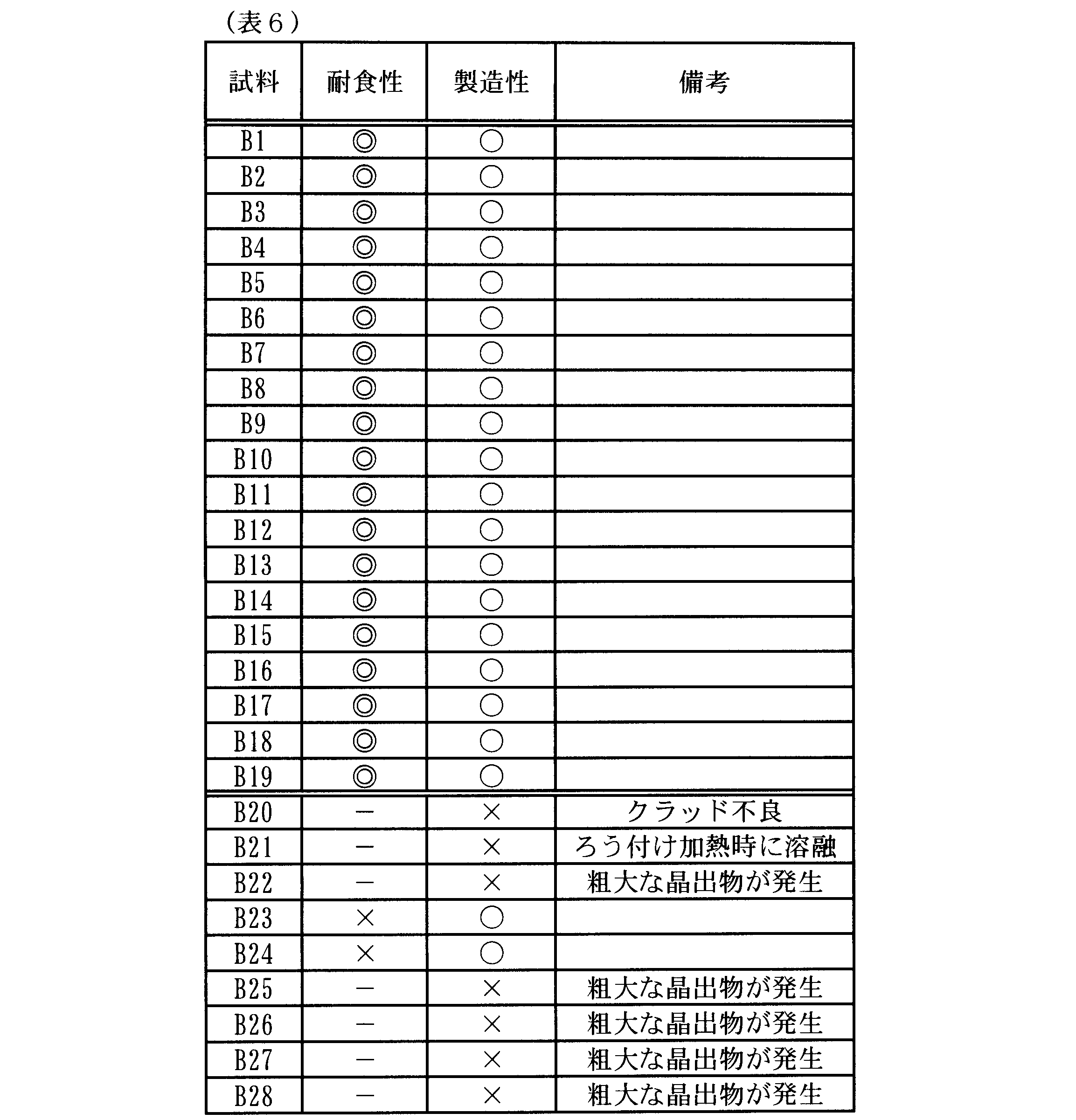
- Table 6 shows the evaluation results of the corrosion resistance and manufacturability of Samples B1 to B28. As shown in the table, Samples B1 to B19, which are examples, gave good results (excellent ( ⁇ ) or good ( ⁇ )) in the evaluation of corrosion resistance. Of course, the evaluation of manufacturability was also good ( ⁇ ). On the other hand, Samples B20 to B28, which are comparative examples, did not give good results in the evaluation of corrosion resistance, or the clad plate was difficult to manufacture, and were not subject to evaluation of corrosion resistance.
- sample B20 since the Mg content of the core material was too large, it was very difficult to produce a clad plate due to the oxide film formed thick on the surface during production.
- sample B21 since the Si content of the core material was too large, the core material melted during brazing heating, making it difficult to manufacture the core material.
- sample B22 the Cu content of the core material was too large, so that coarse crystals were generated during casting of the core material, making it difficult to manufacture the core material.
- sample B23 since the core material had too much Fe content, the corrosion resistance of the core material was lowered, a corroded portion penetrating the test piece was formed, and the evaluation of corrosion resistance was impossible (x).
- Samples B25 to B28 each contained too much Cr, Zr, Ti, and V, so that coarse crystals were generated during casting of the core material, making it difficult to manufacture the core material.
- Table 7 shows the evaluation results of the corrosion resistance and manufacturability of samples C1 to C30. As shown in the table, Samples C1 to C20 as examples showed good results (excellent (() or good ( ⁇ ⁇ )) in the corrosion resistance evaluation. Of course, the evaluation of manufacturability was also good ( ⁇ ). On the other hand, Samples C21 to C30, which are comparative examples, did not give satisfactory results in the evaluation of corrosion resistance, or were difficult to produce a clad plate, and were not subject to evaluation of corrosion resistance.
- Samples C25 to C28 each contained too much Cr, Zr, Ti, and V, so that coarse crystals were generated during casting, and the productivity of the intermediate layer was greatly reduced. Further, as the corrosion progresses, coarse crystallized products are shed and a corroded portion penetrating the test piece is formed, making it difficult to manufacture. In Samples C29 and C30, the difference in Cu content between the intermediate layer and the core material was not sufficient, and the potential balance was lost, so the corrosion resistance could be evaluated ( ⁇ ).
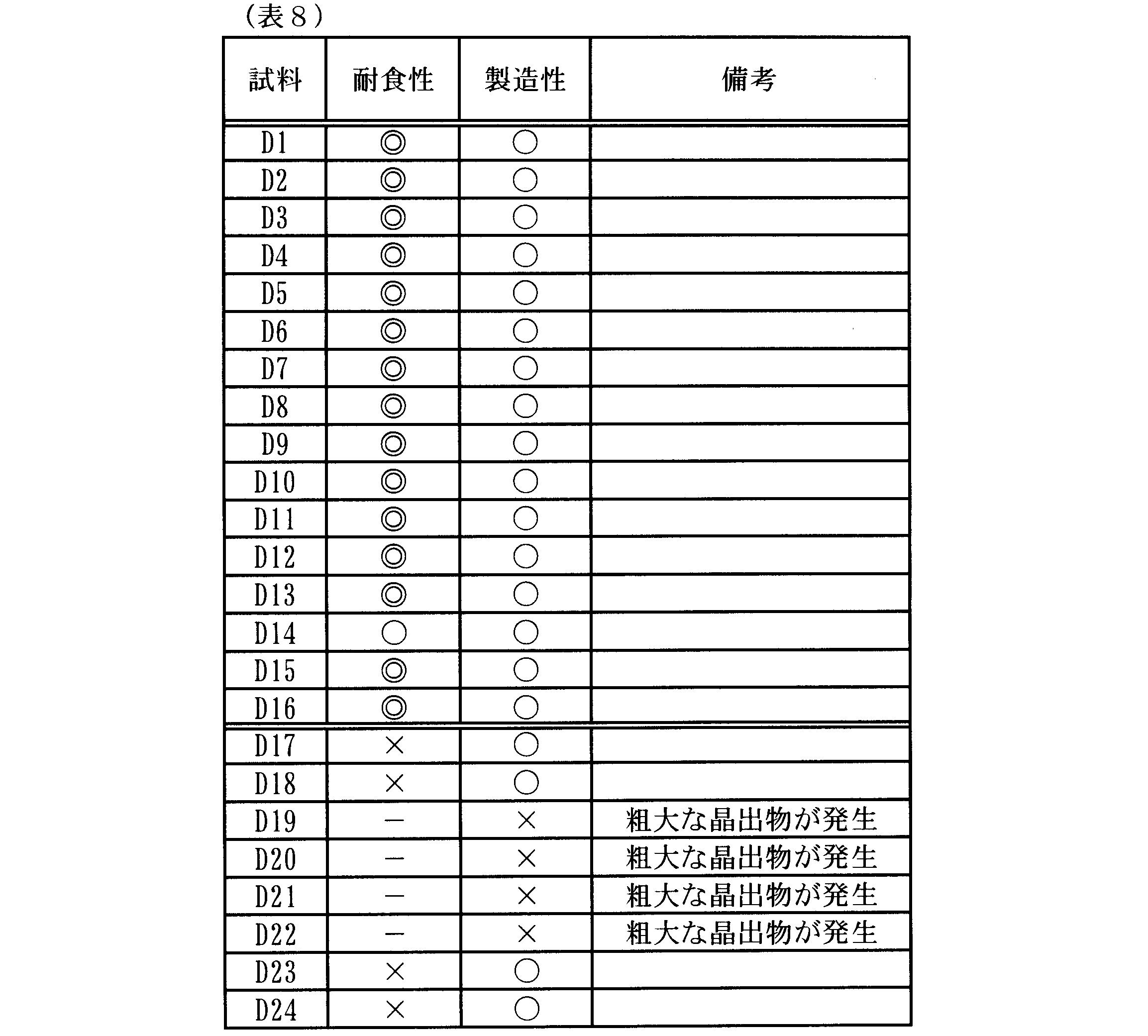
- Table 8 shows the evaluation results of the corrosion resistance and manufacturability of the samples D1 to D24.
- the samples D1 to C16 as examples obtained good results (excellent ( ⁇ ) or good ( ⁇ )) in the corrosion resistance evaluation. Of course, the evaluation of manufacturability was also good ( ⁇ ).
- samples D17 to D24, which are comparative examples did not give good results in the evaluation of corrosion resistance, or the clad plate was difficult to manufacture, and were not subject to evaluation of corrosion resistance.
- the sacrificial material layer had too much Fe content, so that the corrosion resistance of the sacrificial material layer decreased, penetration due to corrosion occurred, and the corrosion resistance evaluation was impossible (x).
- the sacrificial material layer contained too much Ni, so that the corrosion resistance of the sacrificial material layer was reduced, a corroded portion penetrating the test piece was formed, and the corrosion resistance evaluation was impossible (x).
- Samples D19 to D22 since the contents of Cr, Zr, Ti, and V were too large, coarse crystals were generated during the casting of the sacrificial layer, making it difficult to manufacture the sacrificial layer.
- sample D23 since the sacrificial material layer had too much Cu content, the corrosion resistance of the sacrificial material layer was reduced, a corroded portion penetrating the test piece was formed, and the evaluation of corrosion resistance was impossible (x).
- sample D24 the difference in Cu content between the sacrificial material layer and the intermediate layer was not sufficient, and the potential balance was lost, so a corroded portion penetrating the test piece was formed, and corrosion resistance evaluation was impossible (x). there were.
Landscapes
- Engineering & Computer Science (AREA)
- Mechanical Engineering (AREA)
- Physics & Mathematics (AREA)
- Thermal Sciences (AREA)
- General Engineering & Computer Science (AREA)
- Chemical & Material Sciences (AREA)
- Materials Engineering (AREA)
- Metallurgy (AREA)
- Organic Chemistry (AREA)
- Laminated Bodies (AREA)
Abstract
本開示の一局面である熱交換器用アルミニウム合金製クラッド板は、心材、中間層及び犠材層を備える。心材は、Mn:0.4%(質量%、以下同様)以上2.0%以下を含有し、残部がAl及び不可避的不純物からなるアルミニウム合金により構成され、中間層は、Mn:0.2%以上1.8%以下を含有し、残部がAl及び不可避的不純物からなり、かつ、Mn含有量が心材よりも0.2%以上少ないアルミニウム合金により構成され、犠材層は、Mn:0.05%以上1.6%以下、Mg:0.1%以上2.0%以下、Si:0.1%以上1.5%以下を含有し、残部がAl及び不可避的不純物からなり、かつ、Mn含有量が中間層よりも0.2%以上少ないアルミニウム合金により構成されている。
Description
本国際出願は、2016年8月17日に日本国特許庁に出願された日本国特許出願第2016-160100号に基づく優先権を主張するものであり、日本国特許出願第2016-160100号の全内容を本国際出願に参照により援用する。
本開示は、熱交換器用のアルミニウム合金製クラッド板に関する。
例えば、自動車用の熱交換器において、冷却水等の媒体の流路を構成するチューブ材が用いられている。かかるチューブ材としては、アルミニウム合金製クラッド板が用いられている。アルミニウム合金製クラッド板としては、例えば、2層構造のクラッド板及び3層構造のクラッド板がある。2層構造のクラッド板は、例えば、Al-Mn系合金等により構成された心材と、心材の一方の面に被覆(クラッド)され、Al-Si系合金等により構成されたろう材層又はAl-Zn系合金等により構成された犠牲陽極材層(以下、犠材層という)とを有する。3層構造のクラッド板は、例えば、心材と、心材の一方の面に被覆されたろう材層と、心材の他方の面に被覆された犠材層とを有する。
近年、熱交換器の信頼性、耐久性等の向上のため、耐食性に優れたアルミニウム合金製クラッド板が求められている。また、熱交換器の軽量化、小型化等のため、アルミニウム合金製クラッド板の薄肉化が求められている。それに伴ってアルミニウム合金製クラッド板のさらなる耐食性の向上が求められている。
従来のZnを用いた犠牲防食技術では、犠材層にZnを添加し、犠材層の電位を心材の電位よりも卑にすることで防食効果を得ている。しかしながら、Znを添加した犠材層は腐食速度が速いため、アルミニウム合金製クラッド板を薄肉化した場合に早期に犠材層が消費されてしまい、十分な耐食性が得られない。また、近年の世界的なZn需要の高まりにより、将来的にZn資源の枯渇、価格急騰等が生じる懸念がある。このため、Znを用いない防食手法の確立が求められている。
このような状況の中、例えば、特許文献1には、心材の一方の面にAl-Mg-Si系合金により構成された犠材層が被覆され、犠材層中のMg-Si系晶析出物の大きさ及び数を制御したアルミニウム合金製クラッド板が提案されている。また、特許文献2には、心材の一方の面に中間層を介して犠材層が被覆され、心材、中間層、犠材層の順に電位が卑となるように構成されたアルミニウム合金製クラッド板が提案されている。
しかしながら、上記特許文献1のように、Al-Mg-Si系合金により構成された犠材層を用い、犠材層中のMg-Si系晶析出物の大きさ及び数を制御しただけでは、アルミニウム合金製クラッド板の薄肉化に対応できる耐食性を十分に得られない。また、犠材層中のMg-Si系晶析出物の大きさ及び数を制御するために、精密な工程管理が要求される。また、上記特許文献2のように、単に電位が異なる中間層を設けただけでは、中間層を設けずに犠材層の厚さを厚くした場合と本質的に変わらず、耐食性の大きな向上は望めない。
本開示の一局面では、耐食性に優れた熱交換器用のアルミニウム合金製クラッド板を提供することが望ましい。
本開示の一の態様である熱交換器用のアルミニウム合金製クラッド板は、アルミニウム合金により構成された心材、中間層及び犠材層を備え、心材の2つの面のうち少なくとも一方の面に中間層を介して犠材層が被覆されている。心材は、Mn:0.4%(質量%、以下同様)以上2.0%以下を含有し、残部がAl及び不可避的不純物からなるアルミニウム合金により構成されている。中間層は、Mn:0.2%以上1.8%以下を含有し、残部がAl及び不可避的不純物からなり、かつ、Mn含有量が心材よりも0.2%以上少ないアルミニウム合金により構成されている。犠材層は、Mn:0.05%以上1.6%以下、Mg:0.1%以上2.0%以下、Si:0.1%以上1.5%以下を含有し、残部がAl及び不可避的不純物からなり、かつ、Mn含有量が中間層よりも0.2%以上少ないアルミニウム合金により構成されている、又は、Mg:0.1%以上2.0%以下、Si:0.1%以上1.5%以下を含有し、残部がAl及び不可避的不純物からなり、かつ、Mnを不可避的不純物としてのみ含有するアルミニウム合金により構成されている。
上記熱交換器用のアルミニウム合金製クラッド板は、心材と犠材層との間に、上記特定の中間層を設けている。そのため、耐食性を飛躍的に向上させることができる。これにより、従来、犠性防食のために用いられていたZnを含有することなく、優れた耐食性を確保することができる。また、本開示のアルミニウム合金製クラッド板は、薄肉化した場合であっても、様々な過酷な環境に対して良好な耐食性を発揮することができる。
上記熱交換器用のアルミニウム合金製クラッド板において、心材は、さらに、Mg:0.05%以上2.0%以下、Si:0.05%以上1.5%以下、Cu:0.05%以上3.0%以下、Fe:0.1%以上1.0%以下、Ni:0.05%以上0.3%以下、Cr:0.05%以上0.3%以下、Zr:0.05%以上0.3%以下、Ti:0.05%以上0.3%以下、V:0.05%以上0.3%以上から選択される1種以上を含有していてもよい。
中間層は、さらに、Mg:0.05%以上2.0%以下、Si:0.05%以上1.5%以下、Fe:0.1%以上1.0%以下、Ni:0.05%以上0.3%以下、Cr:0.05%以上0.3%以下、Zr:0.05%以上0.3%以下、Ti:0.05%以上0.3%以下、V:0.05%以上0.3%以下から選択される1種以上を含有し、またさらに、Cu:0.05%以上2.8%以下を含有し、Cu含有量が心材よりも0.2%以上少ない、又は、Cuを不可避的不純物としてのみ含有していてもよい。
犠材層は、さらに、Fe:0.05%以上1.0%以下、Ni:0.05%以上0.3%以下、Cr:0.05%以上0.3%以下、Zr:0.05%以上0.3%以下、Ti:0.05%以上0.3%以下、V:0.05%以上0.3%以下から選択される1種以上を含有し、またさらに、Cu:0.05%以上1.5%以下を含有し、Cu含有量が中間層よりも0.2%以上少ない、又は、Cuを不可避的不純物としてのみ含有していてもよい。
また、心材の2つの面のうち第1面に中間層を介して犠材層が被覆され、心材の2つの面のうち第1面にろう材層が被覆されていてもよい。
1…アルミニウム合金製クラッド板、2…心材、3…中間層、4…犠材層、21…第1面(心材の一方の面)
以下、本開示の実施形態について説明する。なお、本開示は、以下の実施形態に限定されるものではなく、本開示の要旨を逸脱しない範囲において種々の態様で実施しうることはいうまでもない。
<アルミニウム合金製クラッド板の構成>
図1に示すように、アルミニウム合金製クラッド板1は、アルミニウム合金により構成された心材2、中間層3及び犠材層4を備えている。心材2は、板状に形成されている。心材2は、2つの面のうち厚さ方向の一方の面である第1面21と、厚さ方向の他方の面である第2面22と、を有する。
図1に示すように、アルミニウム合金製クラッド板1は、アルミニウム合金により構成された心材2、中間層3及び犠材層4を備えている。心材2は、板状に形成されている。心材2は、2つの面のうち厚さ方向の一方の面である第1面21と、厚さ方向の他方の面である第2面22と、を有する。
心材2の第1面21には、中間層3が被覆(クラッド)されている。中間層3の表面には、犠材層4が被覆されている。また、心材2の第2面22には、ろう材層5が被覆されている。すなわち、アルミニウム合金製クラッド板1は、心材2の第1面21に中間層3を介して犠材層4が被覆され、心材2の第2面22にろう材層5が被覆されている。
<アルミニウム合金製クラッド板のアルミニウム合金組成>
アルミニウム合金製クラッド板(以下、適宜、単にクラッド板という)において、心材は、Mn:0.4%(質量%、以下同様)以上2.0%以下を含有し、残部がAl及び不可避的不純物からなるアルミニウム合金により構成されている。
アルミニウム合金製クラッド板(以下、適宜、単にクラッド板という)において、心材は、Mn:0.4%(質量%、以下同様)以上2.0%以下を含有し、残部がAl及び不可避的不純物からなるアルミニウム合金により構成されている。
中間層は、Mn:0.2%以上1.8%以下を含有し、残部がAl及び不可避的不純物からなり、かつ、Mn含有量が心材よりも0.2%以上少ないアルミニウム合金により構成されている。
犠材層は、Mn:0.05%以上1.6%以下、Mg:0.1%以上2.0%以下、Si:0.1%以上1.5%以下を含有し、残部がAl及び不可避的不純物からなり、かつ、Mn含有量が中間層よりも0.2%以上少ないアルミニウム合金により構成されている、又は、Mg:0.1%以上2.0%以下、Si:0.1%以上1.5%以下を含有し、残部がAl及び不可避的不純物からなり、かつ、Mnを不可避的不純物としてのみ含有するアルミニウム合金により構成されている。
すなわち、クラッド板において、心材、中間層及び犠材層を構成するアルミニウム合金は、Mnを含有している。具体的には、心材を構成するアルミニウム合金は、Mn:0.4%以上2.0%以下を含有している。中間層を構成するアルミニウム合金は、Mn:0.2%以上1.8%以下を含有し、Mn含有量が心材よりも0.2%以上少ない。犠材層を構成するアルミニウム合金は、Mn:0.05%以上1.6%以下を含有し、Mn含有量が中間層よりも0.2%以上少ない、又は、Mnを不可避的不純物としてのみ含有している。
次に、各層(心材、中間層、犠材層)を構成するアルミニウム合金に含有されるMnの役割について説明する。
Mnは金属の電位に寄与するため、犠牲防食性に大きな影響を与える。Mnが多く含まれる層では電位がより貴になるため、犠材層よりも中間層に、中間層よりも心材に、よりMnが多く含まれるようにする。これによって、相対的にMn含有量の少ない層が、Mn含有量のより多い層を犠牲防食するようになる。このような犠牲防食効果を得るには、各心材と中間層との間、及び中間層と犠材層との間のMn含有量の差を少なくとも0.2%以上とするとよく、好ましくは0.4%以上、さらに好ましくは0.5%以上とする。なお、不可避的不純物程度のMnを含有していても各層の電位に影響を与えない。
Mnは金属の電位に寄与するため、犠牲防食性に大きな影響を与える。Mnが多く含まれる層では電位がより貴になるため、犠材層よりも中間層に、中間層よりも心材に、よりMnが多く含まれるようにする。これによって、相対的にMn含有量の少ない層が、Mn含有量のより多い層を犠牲防食するようになる。このような犠牲防食効果を得るには、各心材と中間層との間、及び中間層と犠材層との間のMn含有量の差を少なくとも0.2%以上とするとよく、好ましくは0.4%以上、さらに好ましくは0.5%以上とする。なお、不可避的不純物程度のMnを含有していても各層の電位に影響を与えない。
したがって、各層間のMn含有量の差を0.2%以上とするためには、心材は最低0.4%のMnを含む必要があり、同様に中間層は最低0.2%のMnを含む必要がある。しかしながら、各層のMn含有量が2.0%を超えると製造性が低下するおそれがあるため、最もMn含有量が多くなる心材のMn含有量の上限は2.0%とした。同様に、心材のMn含有量が2.0%を超えないように、かつ、心材と中間層との間で0.2%のMn含有量の差を確保するため、中間層のMn含有量の上限は1.8%とした。
各層間の電位差をいくつに設定すればよいかは個々の設計事項であり、使用環境、各層の構成、各層を構成する材料の組成等によって異なるが、例えば、目安として20~200mVとすることが好ましく、30~170mVとすることがより好ましい。各層間の電位差が20mV未満の場合には、各層の犠牲防食性を十分に確保することができないおそれがある。一方、各層間の電位差が200mVを超える場合には、相対的に電位が卑である層の腐食速度が急激に速くなるおそれがある。
さらに、Mnの拡散係数は非常に小さく、アルミニウム合金に添加される他の元素(例えばZn、Cu、Si、Mg等)に比べて数百分の一である。したがって、例えば、中間層及び犠材層を被覆(クラッド)した後の熱処理、ろう付け加熱等の工程において、Mnは実質的に拡散しないと考えてよい。そのため、製造工程の熱履歴によらず、例えクラッド板の厚さ(以下、適宜、単に板厚という)が薄くなったとしても、各層間のMn含有量の差が維持される。言い換えれば、各層間の電位差が維持される。よって、犠材層で生じた腐食の進行が中間層に到達した段階で犠材層と中間層との電位差によって抑制され、腐食の板厚方向への進行が十分に抑制される。
一方、従来の犠牲防食に用いられるZnは、板厚が薄くなると、クラッド板全体に拡散してクラッド板内部に電位差が生じなくなり、犠牲防食が作用しなくなってしまう。板厚がある程度厚い場合でも、ろう付け加熱等によって隣接する層へなだらかなZn濃度(Zn含有量)の勾配が生じ、それに伴って電位差もなだらかに変化するようになる。そのため、犠材層とそれ以外の部分の境界が不明瞭となる。言い換えれば、犠材層の厚さが実質的に厚くなった状態となる。よって、各層間で腐食の進行を抑制する作用は働かない。犠材層に生じた腐食の進行は、中間層又は心材の一部に食い込むまで抑制されない。したがって、クラッド板において、腐食の進行が犠牲防食の作用によって抑制されるまでに、腐食が相当の深さにまで到達することになり(このときの腐食深さを「初期腐食深さ」という)、様々な弊害を引き起こしてしまう。本明細書において、クラッド板において腐食の進行が抑制されるまでに形成された腐食部分の深さを初期腐食深さという。
初期腐食深さが深いことによる弊害は、まず、材料の強度低下である。腐食が板厚方向に進むと、当然腐食に起因して強度が低下する。また、腐食箇所に応力集中が生じやすくなるため、内部又は外部からの圧力等に対して非常に脆弱となってしまう。さらに、腐食メカニズムの観点からも、初期腐食深さが深いことは望ましくない。アルミニウムの腐食形態は、強酸性、強アルカリ性等の環境を除き、孔食となることが知られている。孔食には自己触媒性があることが知られている。孔食は一度成長し始めると、内部は孔食誘起性イオン(塩化物イオン等)が孔食外部から濃化し、さらに強酸性化することが知られている。すなわち、孔食が成長するほど孔食内部はより強腐食環境化していき、さらに孔食成長が早くなるという悪循環を招くことになる。これが孔食の自己触媒性である。そのため、初期腐食深さが深い場合、腐食の内部は外部環境からより隔絶され、溶液の濃化が起こりやすいサイトが形成されてしまう。逆に初期腐食深さが浅い場合、外部からの水流、対流等で、腐食内部液が外部へ容易に流出するため、溶液の濃化が生じにくい。このように、初期腐食深さを深くすることは、孔食の自己触媒性を促進するため望ましくなく、耐食性の低下を招いてしまう。
そこで、拡散係数が非常に小さいMnに着目し、各層間のMn含有量の差が一定値以上となるように、犠材層と心材との間に中間層を設ける。これにより、初期腐食深さを浅くすることができ、よりアルミニウム合金製クラッド板の長寿命化を実現することができる。また、初期腐食深さを浅くするだけであれば、中間層を設けずに心材と犠材層との間にMn含有量の差を設けるだけでよいが、初期腐食深さを浅くするために、犠材層の厚さを厚くしすぎることは望ましくない。一方で、犠材層の厚さが薄すぎると、犠材層が短期間で消耗され、早期に心材が露出してしまう。このようなことから、中間層によって犠材層と中間層との間、中間層と心材との間にそれぞれ大きな電位差を設けることで、各層間で腐食の板厚方向への進行が強く抑制される。
さらに、クラッド板の強度向上の観点から、後述するように、心材にはCu等の易拡散元素が多く含まれる場合がある。易拡散元素は、ろう付け加熱等によって拡散し、各層間の電位差に大きな影響を与えることがある。そのため、犠材層と心材との間に組成を管理した特定の中間層を設けることで、各層間の電位差を保つことができる。隣接する層間のMn含有量の差が0.2%以上、好ましくは0.4%以上確保される構成であれば、犠材層と心材との間に中間層を複数設けてもよい。
以上、各層(心材、中間層、犠材層)を構成するアルミニウム合金に含有されるMnによる効果は、以下のように要約できる。すなわち、実質的に拡散しないMnを用いて各層間にMn含有量の差を設けることで、板厚によらず、腐食の進行を各層間で確実に抑制できる。これにより、初期腐食深さを浅くすることができ、初期腐食深さが大きいことによる弊害を抑制できる。
<各層のアルミニウム合金組成等>
1.中間層
中間層は、Mn:0.2%以上1.8%以下を含有し、残部がAl及び不可避的不純物からなり、かつ、Mn含有量が心材よりも0.2%以上少ないアルミニウム合金により構成されている。Mnは、Al-Mn系金属間化合物として晶出又は析出して、中間層の強度の向上に寄与する。さらに、Al-Mn系金属間化合物は、Feを取り込むことから、添加材又は不可避的不純物としてのFeによる腐食速度増大を抑制する効果を有する。ただし、Mnは、製造条件によって巨大なAl-Mn系金属間化合物として晶出し、中間層の製造性が低下するおそれがある。したがって、中間層のMn含有量を1.5%以下とすることが好ましく、1.0%以下とすることがより好ましい。
1.中間層
中間層は、Mn:0.2%以上1.8%以下を含有し、残部がAl及び不可避的不純物からなり、かつ、Mn含有量が心材よりも0.2%以上少ないアルミニウム合金により構成されている。Mnは、Al-Mn系金属間化合物として晶出又は析出して、中間層の強度の向上に寄与する。さらに、Al-Mn系金属間化合物は、Feを取り込むことから、添加材又は不可避的不純物としてのFeによる腐食速度増大を抑制する効果を有する。ただし、Mnは、製造条件によって巨大なAl-Mn系金属間化合物として晶出し、中間層の製造性が低下するおそれがある。したがって、中間層のMn含有量を1.5%以下とすることが好ましく、1.0%以下とすることがより好ましい。
中間層は、さらに、Mg:0.05%以上2.0%以下、Si:0.05%以上1.5%以下、Fe:0.1%以上1.0%以下、Ni:0.05%以上0.3%以下、Cr:0.05%以上0.3%以下、Zr:0.05%以上0.3%以下、Ti:0.05%以上0.3%以下、V:0.05%以上0.3%以下から選択される1種以上を含有し、かつ、中間層は、さらに、さらに、Cu:0.05%以上2.8%以下を含有し、Cu含有量が心材よりも0.2%以上少ない、又は、Cuを不可避的不純物としてのみ含有していてもよい。中間層において、Cuの含有量は2.8%以下であってもよい。この場合には、耐食性を十分に確保しながら、強度を向上させることができる。以下、各元素を含有することによって得られる効果及び組成範囲の規定理由等について説明する。
Mg、Si:
Mg及びSiは、マトリックス(Al)中に固溶し、又はMg-Si系晶析出物として存在することで強度向上に寄与する。中間層の強度向上効果を考えた場合、Mg及びSiの各含有量は、0.05%以上であることが好ましい。Mg含有量又はSi含有量が0.05%未満の場合には、中間層の強度向上効果が十分に得られないおそれがある。また、Mg含有量が2.0%を超える場合には、中間層の製造時に表面に厚い酸化物層が形成されるため、製造性が低下するおそれがある。Si含有量が1.5%を超える場合には、中間層を構成する材料(アルミニウム合金)の融点の低下が大きくなり、ろう付け等の加熱時に中間層の一部又は全部が溶融するおそれがある。したがって、Mg含有量を2.0%以下とすることが好ましく、Si含有量を1.5%以下とすることが好ましい。
Mg及びSiは、マトリックス(Al)中に固溶し、又はMg-Si系晶析出物として存在することで強度向上に寄与する。中間層の強度向上効果を考えた場合、Mg及びSiの各含有量は、0.05%以上であることが好ましい。Mg含有量又はSi含有量が0.05%未満の場合には、中間層の強度向上効果が十分に得られないおそれがある。また、Mg含有量が2.0%を超える場合には、中間層の製造時に表面に厚い酸化物層が形成されるため、製造性が低下するおそれがある。Si含有量が1.5%を超える場合には、中間層を構成する材料(アルミニウム合金)の融点の低下が大きくなり、ろう付け等の加熱時に中間層の一部又は全部が溶融するおそれがある。したがって、Mg含有量を2.0%以下とすることが好ましく、Si含有量を1.5%以下とすることが好ましい。
Cu:
Cuは、上述のMg及びSiと同様に強度向上に寄与する。しかしながら、Cuは各層の電位分布に与える影響が大きいため、中間層のCu含有量を心材よりも0.2%以上少なくする。また、中間層のCu含有量を心材よりも0.4%以上少なくすることが好ましい。中間層と心材とのCu含有量の差が0.2%未満の場合には、中間層と心材との間の電位差を十分に確保することができないおそれがある。また、後述するように、心材のCu含有量が3.0%を超えると、心材の鋳造割れが生じやすくなり、心材の製造性が低下するおそれがあるため、中間層のCu含有量を2.8%以下とすることが好ましい。すなわち、心材のCu含有量を3.0%以下とし、さらに中間層と心材とのCu含有量の差を0.2%以上とするためには、中間層のCu含有量を2.8%以下とすることが好ましい。ただし、Cu含有量が0.05%未満の不可避的不純物の含有量程度であれば、各層の電位への影響は非常に小さい。したがって、中間層は、Cuを不可避的不純物としてのみ含有していてもよい。なお、中間層にCuを含有させて強度向上効果を得る必要がない場合には、中間層のCu含有量を極力少なくするほうが耐食性向上効果を高めることができる。
Cuは、上述のMg及びSiと同様に強度向上に寄与する。しかしながら、Cuは各層の電位分布に与える影響が大きいため、中間層のCu含有量を心材よりも0.2%以上少なくする。また、中間層のCu含有量を心材よりも0.4%以上少なくすることが好ましい。中間層と心材とのCu含有量の差が0.2%未満の場合には、中間層と心材との間の電位差を十分に確保することができないおそれがある。また、後述するように、心材のCu含有量が3.0%を超えると、心材の鋳造割れが生じやすくなり、心材の製造性が低下するおそれがあるため、中間層のCu含有量を2.8%以下とすることが好ましい。すなわち、心材のCu含有量を3.0%以下とし、さらに中間層と心材とのCu含有量の差を0.2%以上とするためには、中間層のCu含有量を2.8%以下とすることが好ましい。ただし、Cu含有量が0.05%未満の不可避的不純物の含有量程度であれば、各層の電位への影響は非常に小さい。したがって、中間層は、Cuを不可避的不純物としてのみ含有していてもよい。なお、中間層にCuを含有させて強度向上効果を得る必要がない場合には、中間層のCu含有量を極力少なくするほうが耐食性向上効果を高めることができる。
Fe:
Feは、粗大な金属間化合物及び結晶粒を微細化し、中間層の成形性及び加工性向上に寄与する。Fe含有量が0.1%未満の場合には、成形性及び加工性向上効果が十分に得られないおそれがある。Fe含有量が1.0%を超える場合には、中間層自体の耐食性の低下を招くおそれがある。したがって、Fe含有量を0.1%以上1.0%以下とすることが好ましい。
Feは、粗大な金属間化合物及び結晶粒を微細化し、中間層の成形性及び加工性向上に寄与する。Fe含有量が0.1%未満の場合には、成形性及び加工性向上効果が十分に得られないおそれがある。Fe含有量が1.0%を超える場合には、中間層自体の耐食性の低下を招くおそれがある。したがって、Fe含有量を0.1%以上1.0%以下とすることが好ましい。
Ni:
Niは、Ni系化合物が微細かつ均一に分布し、腐食を分散させる効果を有するため、耐食性向上に寄与する。Ni含有量が0.05%未満の場合には、耐食性向上効果が十分に得られないおそれがある。Ni含有量が0.3%を超える場合には、腐食速度が増大するおそれがある。したがって、Ni含有量を0.05%以上0.3%以下とすることが好ましい。
Niは、Ni系化合物が微細かつ均一に分布し、腐食を分散させる効果を有するため、耐食性向上に寄与する。Ni含有量が0.05%未満の場合には、耐食性向上効果が十分に得られないおそれがある。Ni含有量が0.3%を超える場合には、腐食速度が増大するおそれがある。したがって、Ni含有量を0.05%以上0.3%以下とすることが好ましい。
Cr、Zr、Ti、V:
Cr、Zr、Ti及びVは、耐食性、特に耐孔食性の向上に寄与する。アルミニウム合金中にCr、Zr、Ti及びVが添加されると、各元素における濃度の高い領域と濃度の低い領域とが板厚方向に沿って交互に積層状に分布する。ここで、各元素における濃度の低い領域は、濃度の高い領域よりも優先的に腐食されるため、腐食の形態が層状となる。その結果、板厚方向への腐食進行が抑制され、中間層の耐孔食性が向上する。Cr、Zr、Ti及びVのいずれかの含有量が0.05%未満の場合には、耐孔食性向上効果が十分に得られないおそれがある。Cr、Zr、Ti及びVのいずれかの含有量が0.30%を超える場合には、中間層の鋳造時に粗大な化合物が生じ、中間層の製造性が低下するおそれがある。したがって、Cr、Zr、Ti及びVの各含有量を0.05%以上0.30%以下とすることが好ましい。
Cr、Zr、Ti及びVは、耐食性、特に耐孔食性の向上に寄与する。アルミニウム合金中にCr、Zr、Ti及びVが添加されると、各元素における濃度の高い領域と濃度の低い領域とが板厚方向に沿って交互に積層状に分布する。ここで、各元素における濃度の低い領域は、濃度の高い領域よりも優先的に腐食されるため、腐食の形態が層状となる。その結果、板厚方向への腐食進行が抑制され、中間層の耐孔食性が向上する。Cr、Zr、Ti及びVのいずれかの含有量が0.05%未満の場合には、耐孔食性向上効果が十分に得られないおそれがある。Cr、Zr、Ti及びVのいずれかの含有量が0.30%を超える場合には、中間層の鋳造時に粗大な化合物が生じ、中間層の製造性が低下するおそれがある。したがって、Cr、Zr、Ti及びVの各含有量を0.05%以上0.30%以下とすることが好ましい。
2.犠材層
犠材層は、犠牲陽極材により構成された層である。犠材層は、Mg:0.1%以上2.0%以下、Si:0.1%以上1.5%以下、Mn:0.05%以上1.6%以下を含有し、残部がAl及び不可避的不純物からなり、かつ、Mn含有量が中間層よりも0.2%以上少ないアルミニウム合金により構成されている、又は、Mg:0.1%以上2.0%以下、Si:0.1%以上1.5%以下を含有し、残部がAl及び不可避的不純物からなり、かつ、Mnを不可避的不純物としてのみ含有するアルミニウム合金により構成されている。犠材層におけるMnの含有量は1.6%以下であってもよい。
犠材層は、犠牲陽極材により構成された層である。犠材層は、Mg:0.1%以上2.0%以下、Si:0.1%以上1.5%以下、Mn:0.05%以上1.6%以下を含有し、残部がAl及び不可避的不純物からなり、かつ、Mn含有量が中間層よりも0.2%以上少ないアルミニウム合金により構成されている、又は、Mg:0.1%以上2.0%以下、Si:0.1%以上1.5%以下を含有し、残部がAl及び不可避的不純物からなり、かつ、Mnを不可避的不純物としてのみ含有するアルミニウム合金により構成されている。犠材層におけるMnの含有量は1.6%以下であってもよい。
犠材層としては、自己腐食がより小さいものが望ましい。自己腐食とは、犠牲防食に寄与しない犠材層の腐食量のことである。すなわち、(犠材層の自己腐食量)+(犠牲防食による犠材層の消耗量)=(犠材層の腐食量の合計)であることから、自己腐食量を抑制することにより、犠材層全体の腐食量を抑制できる。
そこで、犠材層をAl-Mg-Si系合金により構成することで、Al-Mg-Si系合金中に不可避的に存在するMg-Si系晶析出物が耐食性向上に寄与し、熱交換器の使用環境で優れた耐食性を得ることができる。熱交換器は、その性質上、作動中は高温に曝される。このとき、熱交換器の水と触れている部分には、耐食性の優れた水和酸化物皮膜が生成する。例えば、熱交換器のチューブ材の内部には水系冷媒等が循環していているため、チューブ材の表面には水和酸化物皮膜が形成されることになる。このとき、犠材層表面に存在するMg-Si系晶析出物からMgが優先的に溶出する。これにともなってSiも溶出する。溶出したSiが水和酸化物皮膜中に取り込まれる。水和酸化物皮膜に取り込まれたSiは、水和酸化物皮膜の欠陥を修復し、耐食性向上に寄与すると考えられる。そのため、より耐食性に優れた水和酸化物皮膜が形成され、犠材層の自己腐食が抑制される。また、Mgが溶出したMg-Si系晶析出物は、Siが濃縮されることになり、腐食の進行を抑制する効果が得られる。さらに、Mg-Si系晶析出物は電位が非常に低いため、Mg-Si系晶析出物が相対的に多い犠材層表面の電位はより卑な値となる効果もある。このように、犠材層をAl-Mg-Si系合金により構成することで、従来、犠性防食に用いられていたZnによらず、高い防食効果が得られる。
上記の効果を得るため、犠材層のMg含有量を0.1%以上2.0%以下とし、Si含有量を0.1%以上1.5%以下とする。また、耐食性向上の観点から、犠材層のMg及びSiの各含有量を0.15%以上1.0%以下とすることが好ましい。Mg及びSiの各含有量が0.1%未満の場合には、Mg-Si系晶析出物量が少ないため、上記の効果が十分に得られないおそれがある。一方、Mg含有量が2.0%を超える場合には、製造時に犠材層表面の酸化膜厚さが厚くなり、良好なクラッド板を得ることが困難となるおそれがある。Si含有量が1.5%を超える場合には、犠材層を構成する材料(アルミニウム合金)の融点が低下するため、ろう付け等の加熱時に犠材層の一部又は全部が溶融してしまう。
また、犠材層は、さらに、Fe:0.05%以上1.0%以下、Ni:0.05以上0.3%以下、Cr:0.05%以上0.3%以下、Zr:0.05%以上0.3%以下、Ti:0.05%以上0.3%以下、V:0.05%以上0.3%以下から選択される1種以上を含有し、かつ、犠材層は、さらに、Cu:0.05%以上1.5%以下を含有し、Cu含有量が中間層よりも0.2%以上少ない、又は、Cuを不可避的不純物としてのみ含有していてもよい。犠材層におけるCuの含有量は1.5%以下であってもよい。この場合には、耐食性を十分に確保しながら、強度を向上させることができる。Fe、Ni、Cr、Zr、Ti及びVを含有することによって得られる効果及び組成範囲の規定理由は、上述した中間層と同様である。
クラッド板の板厚が特に薄い場合等では、強度向上のために犠材層へのCu添加が必要とされる場合がある。強度向上効果を十分に得るためには、犠材層のCu含有量を0.05%以上とすることが好ましいが、犠材層のCu含有量が1.5%を超える場合には、犠材層の腐食速度が大きくなってしまうおそれがある。また、犠材層の耐食性を確保するために、犠材層のCu含有量を中間層よりも0.2%以上少なくすることが好ましく、0.4%以上少なくすることがより好ましい。ただし、犠材層のCu含有量が0.05%未満の不可避的不純物程度であれば、各層の電位への影響は非常に小さい。したがって、中間層は、Cuを不可避的不純物としてのみ含有していてもよい。なお、犠材層にCuを含有させて強度向上効果を得る必要がない場合には、犠材層のCu含有量を極力少なくするほうが耐食性向上効果を高めることができる。
3.心材
心材は、Mn:0.4%以上2.0%以下を含有し、残部がAl及び不可避的不純物からなるアルミニウム合金により構成されている。Mnは、Al-Mn系金属間化合物として晶出又は析出して、強度の向上に寄与する。さらに、Al-Mn系金属間化合物は、Feを取り込むことから、添加材又は不可避的不純物としてのFeによる腐食速度増大を抑制する効果を有する。ただし、Mnは、製造条件によって巨大なAl-Mn系金属間化合物として晶出し、製造性が低下するおそれがある。したがって、心材のMn含有量を1.50%以下とすることが好ましく、1.0%以下とすることがより好ましい。
心材は、Mn:0.4%以上2.0%以下を含有し、残部がAl及び不可避的不純物からなるアルミニウム合金により構成されている。Mnは、Al-Mn系金属間化合物として晶出又は析出して、強度の向上に寄与する。さらに、Al-Mn系金属間化合物は、Feを取り込むことから、添加材又は不可避的不純物としてのFeによる腐食速度増大を抑制する効果を有する。ただし、Mnは、製造条件によって巨大なAl-Mn系金属間化合物として晶出し、製造性が低下するおそれがある。したがって、心材のMn含有量を1.50%以下とすることが好ましく、1.0%以下とすることがより好ましい。
また、心材は、さらに、Mg:0.05%以上2.0%以下、Si:0.05%以上1.5%以下、Cu:0.05%以上3.0%以下、Fe:0.1%以上1.0%以下、Ni:0.05%以上0.3%以下、Cr:0.05%以上0.3%以下、Zr:0.05%以上0.3%以下、Ti:0.05%以上0.3%以下、V:0.05%以上0.3%以上から選択される1種以上を含有していてもよい。この場合には、心材の耐食性を十分に確保しながら、心材の強度を向上させることができる。Mg、Si、Fe、Ni、Cr、Zr、Ti及びVを含有することによって得られる効果及び組成範囲の規定理由は、上述した中間層と同様である。
また、心材にCuを添加すると、心材の強度向上効果に加えて、心材の電位が中間層及び犠材層よりも相対的に貴となる効果があり、中間層及び犠材層の心材に対する犠牲防食効果が高くなる。心材のCu含有量が0.05%未満の場合には、各層の電位への影響が非常に小さいが、強度向上効果が十分に得られないおそれがある。一方、心材のCu含有量が3.0%を超える場合には、心材の鋳造割れが生じやすくなり、心材の製造性が低下するおそれがある。
4.ろう材層
ろう材層に用いられるアルミニウム材は、特に限定されるものではない。ろう材層に用いられるアルミニウム材としては、通常のろう付けにおいて用いられるAl-Si系合金ろう材等を用いることができ、例えば、JIS4343、JIS4045、JIS4047等の各アルミニウム合金(Al-7~13%Si)等を用いることができる。
ろう材層に用いられるアルミニウム材は、特に限定されるものではない。ろう材層に用いられるアルミニウム材としては、通常のろう付けにおいて用いられるAl-Si系合金ろう材等を用いることができ、例えば、JIS4343、JIS4045、JIS4047等の各アルミニウム合金(Al-7~13%Si)等を用いることができる。
<その他>
上記アルミニウム合金製クラッド板において、心材、中間層及び犠材層を構成するアルミニウム合金には、耐食性等の特性を損なわない範囲において、上述した元素以外の元素が含有されていてもよい。例えば、不可避的不純物として、Na、Ca等が単独で0.05%以上、合計で0.15%以下含有されていてもよい。
上記アルミニウム合金製クラッド板において、心材、中間層及び犠材層を構成するアルミニウム合金には、耐食性等の特性を損なわない範囲において、上述した元素以外の元素が含有されていてもよい。例えば、不可避的不純物として、Na、Ca等が単独で0.05%以上、合計で0.15%以下含有されていてもよい。
中間層の厚さは、3~200μmとすることが好ましい。中間層の厚さが3μm未満の場合には、製造が困難となるおそれがあり、さらに中間層で初期腐食を抑制する効果が十分に得られず、腐食が心材にまで容易に到達してしまうおそれがある。一方、中間層の厚さが200μmを超える場合には、板厚全体に占める中間層の厚さが心材の厚さに比べて厚くなりすぎ、クラッド板全体の機械的性質が低下するおそれがある。
犠材層の厚さは、犠材層における初期腐食深さを浅くするという観点から、2~100μmとすることが好ましく、5~50μmとすることがより好ましい。犠材層の厚さが2μm未満の場合には、犠材層の製造が困難となるおそれがあり、さらに犠材層が短期間に消耗してしまい、クラッド板の初期腐食深さを浅くするという効果が十分に得られないおそれがある。一方、犠材層の厚さが100μmを超える場合には、初期腐食深さが大きくなりすぎ、クラッド板の耐食性が低下するおそれがある。
中間層のクラッド率は、製造性の観点から2~30%とすることが好ましく、5~20%とすることがより好ましい。中間層のクラッド率が2%未満の場合及び30%を超える場合には、クラッド板の製造が困難となるおそれがある。ここで、中間層のクラッド率とは、クラッド板全体の厚さに対する中間層の厚さの比率である。
犠材層のクラッド率は、中間層と同様に、クラッド板の製造性の観点から2~30%とすることが好ましく、5~20%とすることがより好ましい。犠材層のクラッド率が2%未満の場合及び30%を超える場合には、クラッド板の製造が困難となるおそれがある。ここで、犠材層のクラッド率とは、クラッド板全体の厚さに対する犠材層の厚さの比率である。
上記アルミニウム合金製クラッド板において、心材の一方の面に中間層を介して犠材層が被覆され、心材の他方の面にろう材層が被覆されていてもよい。この場合には、クラッド板のろう付けが容易となる。例えば、クラッド板に曲げ加工を施し、その両端部の重ね合わせ部分をろう付け接合して、熱交換器のチューブ材を作製することが容易となる。
ろう材層の厚さは、特に限定されるものではないが、例えば、10~50μmとすることが好ましい。ろう材層の片面クラッド率は、5~30%とすることが好ましい。ここで、ろう材層の片面クラッド率とは、クラッド板全体の厚さに対する、クラッド板の片面側に設けたろう材層の厚さの比率である。クラッド板全体の厚さは、50~250μmとすることが好ましく、70~220μmとすることがより好ましい。
心材、中間層及び犠材層を備える上記アルミニウム合金製クラッド板は、通常の製造方法により製造される。また、上記アルミニウム合金製クラッド板は、チューブ材、フィン材、ヘッダープレート等の熱交換器部材として用いられる。上記アルミニウム合金製クラッド板は、特に、薄肉化が求められるチューブ材として好適に用いられる。
上記アルミニウム合金製クラッド板(以下、適宜、単にクラッド板という)の実施例について、比較例と対比しながら、表1~表8を用いて説明する。以下に示す実施例は、本開示の一実施態様を示すものであり、本開示は何らこれらに限定されるものではない。
<アルミニウム合金製クラッド板の作製>
心材には、表1~4に示す組成の合金を用いた。心材用合金を半連続鋳造法により鋳造し、心材用鋳塊を得た。その後、心材用鋳塊に対して、520℃、6時間の均質化処理を施し、所定の厚さとなるように面削を施した。
心材には、表1~4に示す組成の合金を用いた。心材用合金を半連続鋳造法により鋳造し、心材用鋳塊を得た。その後、心材用鋳塊に対して、520℃、6時間の均質化処理を施し、所定の厚さとなるように面削を施した。
中間層及び犠材層には、表1~4に示す組成の合金を用いた。中間層用合金及び犠材層用合金を半連続鋳造法により鋳造し、中間層用鋳塊及び犠材層用鋳塊を得た。その後、中間層用鋳塊及び犠材層用鋳塊に対して面削を施し、500℃で熱間圧延を施し、所定の厚さの板形状とした。なお、熱間圧延前に、中間層用鋳塊及び犠材層用鋳塊に対して、均質化処理を施してもよい。
なお、表1~4に示す合金組成は、発光分光分析装置を用いて鋳造後の鋳塊を測定したものである。また、面削後の心材用鋳塊の厚さ、熱間圧延後の中間層用鋳塊及び犠材層用鋳塊の厚さは、中間層及び犠材層の各クラッド率が5%となるように調整した。ここで、中間層のクラッド率は、作製するクラッド板の厚さに対する中間層の厚さの比率である。犠材層のクラッド率は、作製するクラッド板の厚さに対する犠材層の厚さの比率である。
次いで、心材用鋳塊の片面に中間層用鋳塊を重ね、さらに中間層用鋳塊上に犠材層用鋳塊を重ねた。この重ね合わせ材を通常のクラッド板の製造方法にしたがって520℃で熱間圧延し、厚さ3.5mmの3層クラッド板とした。そして、3層クラッド板に対して板厚が0.20mmとなるまで冷間圧延を施し、さらに360℃で3時間の焼鈍を施した後、冷間圧延を施した。これにより、全体厚さ0.15mm、中間層及び犠材層の各クラッド率が5%(すなわち中間層及び犠材層の各厚さが7.5μm)の3層クラッド板を得た。その後、3層クラッド板について、窒素雰囲気中又は真空中(1×10⁻³Pa)において、600℃で3分保持するというろう付けに相当する加熱条件を施した。
以上により、実施例及び比較例のクラッド板を得た。なお、表1~4に示すように、実施例のクラッド板は、試料A1~A12、B1~B28、C1~C30、D1~D24であり、比較例のクラッド板は、試料A13~A20である。
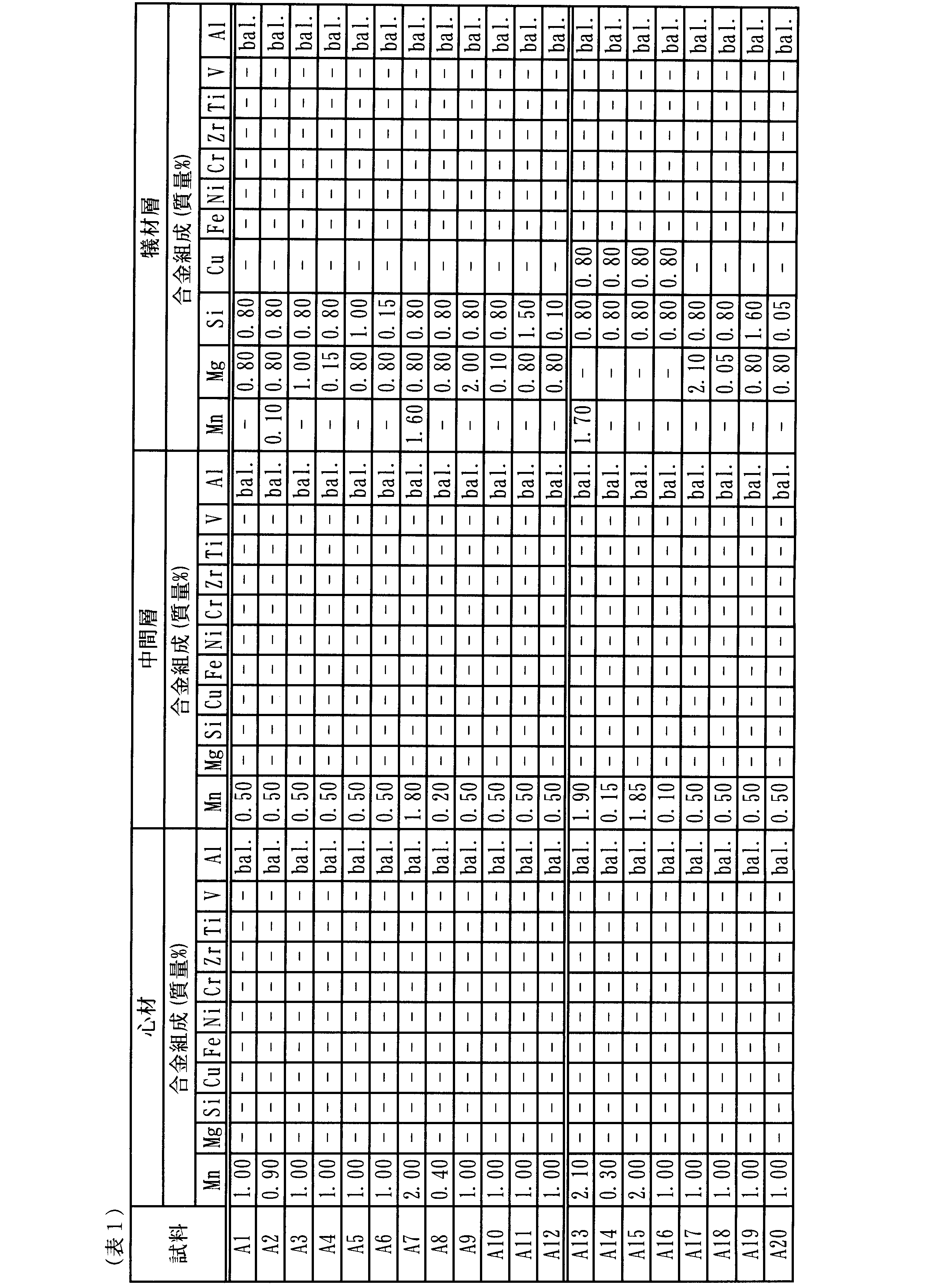
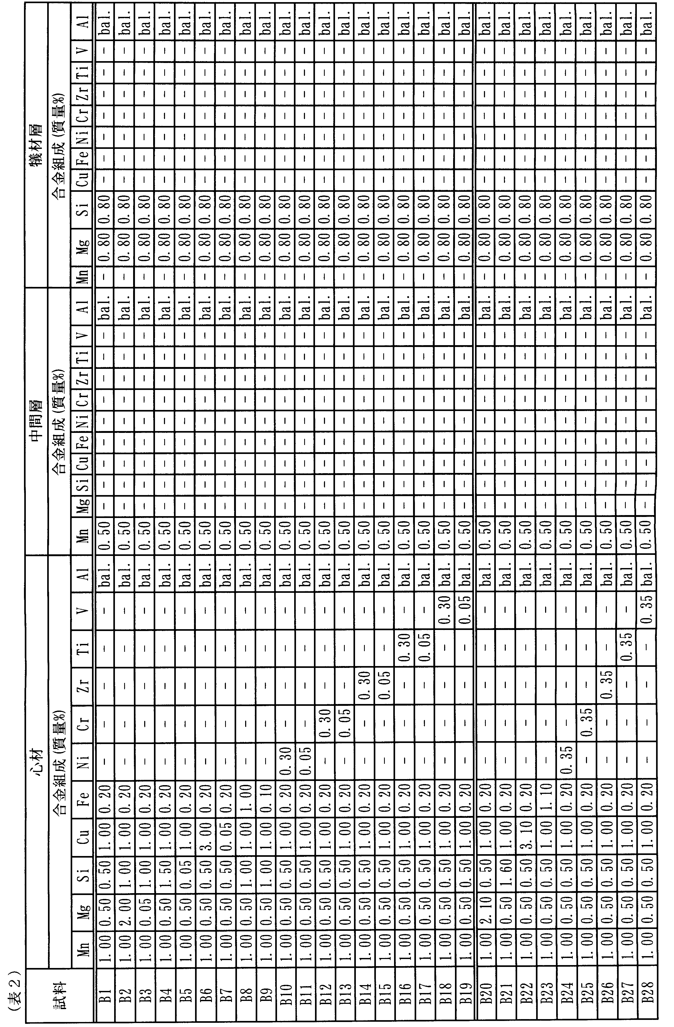


作製したクラッド板に対して、水系冷媒環境を模擬した循環サイクル試験を実施し、耐食性を評価した。まず、作製したクラッド板から50×100mmの長方形板状の試験片を切り出した。試験片の試験面は犠材層をクラッドした面である。試験片の非試験面及び端面はマスキングした。
次いで、Cl-:195ppm、SO4
2-:60ppm、Cu2+:1ppm、Fe2+:30ppmを含有する88℃の水溶液を、試験片の試験面に対して比液量6mL/cm2、流速2m/秒で8時間流通させた。その後、試験片を16時間放置した。このような加熱流通及び放置からなるサイクルを3ヶ月間行った。
循環サイクル試験後、試験片の表面の腐食生成物を除去し、試験片の腐食深さを測定した。試験片の測定箇所は10箇所とし、それらの最大値を腐食深さとした。耐食性の評価は、試験片の腐食深さが60μm以下の場合を優良(◎)、腐食深さが60μm超え75μm以下の場合を良(○)、腐食深さが75μm超え100μm以下の場合を可(△)、腐食深さが100μmを超える又は腐食によって試験片を腐食部分が貫通した場合を不可(×)とした。
<製造性の評価>
クラッド板を作製するに当たって、その製造性に問題がなかったものを良(○)、何らかの理由により製造が困難であったものを不良(×)とし、表5~表8の備考欄にその理由を記載した。
クラッド板を作製するに当たって、その製造性に問題がなかったものを良(○)、何らかの理由により製造が困難であったものを不良(×)とし、表5~表8の備考欄にその理由を記載した。
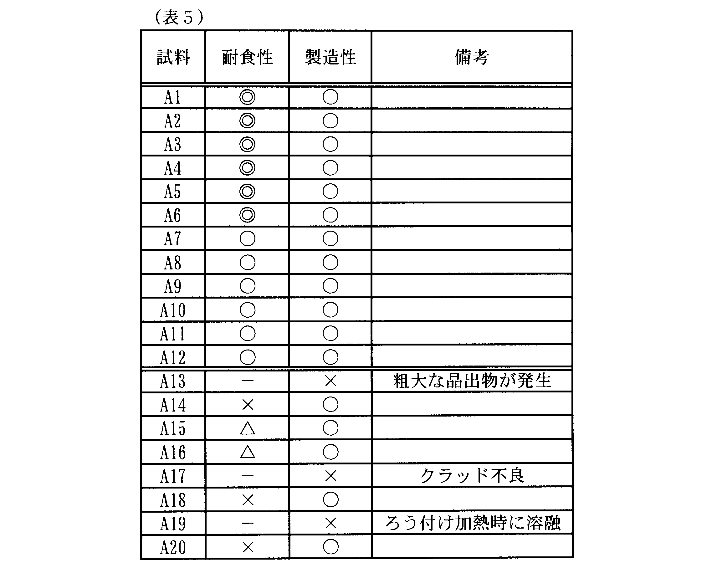

同表に示すとおり、実施例である試料A1~A12は、耐食性の評価において良好な結果(優良(◎)又は良(○))が得られた。もちろん、製造性の評価も良(○)であった。一方、比較例である試料A13~A20は、耐食性の評価において良好な結果が得られなかったか、あるいはクラッド板の製造が困難であり、耐食性の評価対象とならなかった。
試料A13は、心材のMn含有量が2.0%を越えているため、鋳造時に粗大な晶出物が発生し、製造が困難となった。試料A14は、犠材層と中間層との間のMn含有量の差、中間層と心材との間のMn含有量の差が十分ではなく、腐食による貫通が生じ、耐食性の評価が不可(×)であった。試料A15は、中間層と心材との間のMn含有量の差が十分ではなく、耐食性の評価が可(△)であった。試料A16は、犠材層と中間層との間のMn含有量の差が十分ではなく、耐食性の評価が可(△)であった。試料A17は、犠材層のMg含有量が多すぎたため、製造時に表面に厚く形成された酸化物皮膜により、クラッド板の製造が非常に困難となった。試料A18は、犠材層のMg含有量が少なすぎたため、犠材層自体の耐食性が劣り、犠材層が短期間のうちに消耗してしまい、試験片を貫通する腐食部分が形成され、耐食性の評価が不可(×)であった。試料A19は、犠材層のSi含有量が多すぎたため、ろう付け加熱時に犠材層が溶融してしまい、製造が困難となった。試料A20は、犠材層のSi含有量が少なすぎたため、Mg-Si系晶析出物がほとんど存在せず、試験片を貫通する腐食部分が形成され、耐食性の評価が不可(×)であった。
表6に、試料B1~B28の耐食性及び製造性の評価結果を示す。
同表に示すとおり、実施例である試料B1~B19は、耐食性の評価において良好な結果(優良(◎)又は良(○))が得られた。もちろん、製造性の評価も良(○)であった。一方、比較例である試料B20~B28は、耐食性の評価において良好な結果が得られなかったか、あるいはクラッド板の製造が困難であり、耐食性の評価対象とならなかった。
同表に示すとおり、実施例である試料B1~B19は、耐食性の評価において良好な結果(優良(◎)又は良(○))が得られた。もちろん、製造性の評価も良(○)であった。一方、比較例である試料B20~B28は、耐食性の評価において良好な結果が得られなかったか、あるいはクラッド板の製造が困難であり、耐食性の評価対象とならなかった。
試料B20は、心材のMg含有量が多すぎたため、製造時に表面に厚く形成された酸化物皮膜により、クラッド板の製造が非常に困難となった。試料B21は、心材のSi含有量が多すぎたため、ろう付け加熱時に心材が溶融してしまい、心材の製造が困難となった。試料B22は、心材のCu含有量が多すぎたため、心材の鋳造時に粗大な晶出物が発生し、心材の製造が非常に困難となった。試料B23は、心材のFe含有量が多すぎたため、心材の耐食性が低下し、試験片を貫通する腐食部分が形成され、耐食性の評価が不可(×)であった。試料B24は、心材のNi含有量が多すぎたため、心材の耐食性が低下し、試験片を貫通する腐食部分が形成され、耐食性の評価が不可(×)であった。試料B25~B28は、それぞれCr、Zr、Ti、Vの含有量が多すぎたため、心材の鋳造時に粗大な晶出物が発生し、心材の製造が困難となった。
表7に、試料C1~C30の耐食性及び製造性の評価結果を示す。
同表に示すとおり、実施例である試料C1~C20は、耐食性の評価において良好な結果(優良(◎)又は良(○))が得られた。もちろん、製造性の評価も良(○)であった。一方、比較例である試料C21~C30は、耐食性の評価において良好な結果が得られなかったか、あるいはクラッド板の製造が困難であり、耐食性の評価対象とならなかった。
同表に示すとおり、実施例である試料C1~C20は、耐食性の評価において良好な結果(優良(◎)又は良(○))が得られた。もちろん、製造性の評価も良(○)であった。一方、比較例である試料C21~C30は、耐食性の評価において良好な結果が得られなかったか、あるいはクラッド板の製造が困難であり、耐食性の評価対象とならなかった。
試料C21は、中間層のMg含有量が多すぎたため、製造時に表面に厚く形成された酸化物皮膜により、クラッド板の製造が非常に困難となった。試料C22は、中間層のSi含有量が多すぎたため、ろう付け加熱時に中間層が溶融してしまい、中間層の製造が困難となった。試料C23は、中間層のFe含有量が多すぎたため、中間層の耐食性が低下し、試験片を貫通する腐食部分が形成され、耐食性の評価が不可(×)であった。試料C24は、中間層のNi含有量が多すぎたため、中間層の耐食性が低下し、試験片を貫通する腐食部分が形成され、耐食性の評価が不可(×)であった。試料C25~C28は、それぞれCr、Zr、Ti、Vの含有量が多すぎたため、鋳造時に粗大な晶出物が発生し、中間層の製造性が大きく低下した。また、腐食の進行に伴って粗大な晶出物が脱粒してしまい、試験片を貫通する腐食部分が形成され、製造が困難となった。試料C29、C30は、中間層と心材との間のCu含有量の差が十分ではなく、電位バランスが崩れたため、耐食性の評価が可(△)であった。
表8に、試料D1~D24の耐食性及び製造性の評価結果を示す。
同表に示すとおり、実施例である試料D1~C16は、耐食性の評価において良好な結果(優良(◎)又は良(○))が得られた。もちろん、製造性の評価も良(○)であった。一方、比較例である試料D17~D24は、耐食性の評価において良好な結果が得られなかったか、あるいはクラッド板の製造が困難であり、耐食性の評価対象とならなかった。
同表に示すとおり、実施例である試料D1~C16は、耐食性の評価において良好な結果(優良(◎)又は良(○))が得られた。もちろん、製造性の評価も良(○)であった。一方、比較例である試料D17~D24は、耐食性の評価において良好な結果が得られなかったか、あるいはクラッド板の製造が困難であり、耐食性の評価対象とならなかった。
試料D17は、犠材層のFe含有量が多すぎたため、犠材層の耐食性が低下し、腐食による貫通が生じ、耐食性の評価が不可(×)であった。試料D18は、犠材層のNi含有量が多すぎたため、犠材層の耐食性が低下し、試験片を貫通する腐食部分が形成され、耐食性の評価が不可(×)であった。試料D19~D22は、それぞれCr、Zr、Ti、Vの含有量が多すぎたため、犠材層の鋳造時に粗大な晶出物が発生し、犠材層の製造が困難となった。試料D23は、犠材層のCu含有量が多すぎたため、犠材層の耐食性が低下し、試験片を貫通する腐食部分が形成され、耐食性の評価が不可(×)であった。試料D24は、犠材層と中間層との間のCu含有量の差が十分ではなく、電位バランスが崩れたため、試験片を貫通する腐食部分が形成され、耐食性の評価が不可(×)であった。
Claims (8)
- 熱交換器用のアルミニウム合金製クラッド板であって、
アルミニウム合金により構成された心材、中間層及び犠材層を備え、
前記心材の2つの面のうち少なくとも一方の面に前記中間層を介して前記犠材層が被覆され、
前記心材は、Mn:0.4%(質量%、以下同様)以上2.0%以下を含有し、残部がAl及び不可避的不純物からなるアルミニウム合金により構成され、
前記中間層は、Mn:0.2%以上1.8%以下を含有し、残部がAl及び不可避的不純物からなり、かつ、Mn含有量が前記心材よりも0.2%以上少ないアルミニウム合金により構成され、
前記犠材層は、Mn:0.05%以上1.6%以下、Mg:0.1%以上2.0%以下、Si:0.1%以上1.5%以下を含有し、残部がAl及び不可避的不純物からなり、かつ、Mn含有量が前記中間層よりも0.2%以上少ないアルミニウム合金により構成されている、又は、Mg:0.1%以上2.0%以下、Si:0.1%以上1.5%以下を含有し、残部がAl及び不可避的不純物からなり、かつ、Mnを不可避的不純物としてのみ含有するアルミニウム合金により構成されている、熱交換器用のアルミニウム合金製クラッド板。 - 前記心材は、さらに、Mg:0.05%以上2.0%以下、Si:0.05%以上1.5%以下、Cu:0.05%以上3.0%以下、Fe:0.1%以上1.0%以下、Ni:0.05%以上0.3%以下、Cr:0.05%以上0.3%以下、Zr:0.05%以上0.3%以下、Ti:0.05%以上0.3%以下、V:0.05%以上0.3%以上から選択される1種以上を含有する、請求項1に記載の熱交換器用のアルミニウム合金製クラッド板。
- 前記中間層は、さらに、Mg:0.05%以上2.0%以下、Si:0.05%以上1.5%以下、Fe:0.1%以上1.0%以下、Ni:0.05%以上0.3%以下、Cr:0.05%以上0.3%以下、Zr:0.05%以上0.3%以下、Ti:0.05%以上0.3%以下、V:0.05%以上0.3%以下から選択される1種以上を含有し、
かつ、前記中間層は、さらに、Cu:0.05%以上2.8%以下を含有し、Cu含有量が前記心材よりも0.2%以上少ない、又は、Cuを不可避的不純物としてのみ含有する、請求項1又は2に記載の熱交換器用のアルミニウム合金製クラッド板。 - 前記犠材層は、さらに、Fe:0.05%以上1.0%以下、Ni:0.05以上0.3%以下、Cr:0.05%以上0.3%以下、Zr:0.05%以上0.3%以下、Ti:0.05%以上0.3%以下、V:0.05%以上0.3%以下から選択される1種以上を含有し、
かつ、前記犠材層は、さらに、Cu:0.05%以上1.5%以下を含有し、Cu含有量が前記中間層よりも0.2%以上少ない、又は、Cuを不可避的不純物としてのみ含有する、請求項1~3のいずれか1項に記載の熱交換器用のアルミニウム合金製クラッド板。 - 前記心材の前記2つの面のうち第1面に前記中間層を介して前記犠材層が被覆され、前記心材の前記2つの面のうち第2面にろう材層が被覆されている、請求項1~4のいずれか1項に記載の熱交換器用のアルミニウム合金製クラッド板。
- 前記ろう材層は、Al-Si系合金により構成されている、請求項1~5のいずれか1項に記載の熱交換器用のアルミニウム合金製クラッド板。
- 前記中間層の厚みは、3~200μmである、請求項1~6のいずれか1項に記載の熱交換器用のアルミニウム合金製クラッド板。
- 前記犠材層の厚みは2~100μmである、請求項1~7のいずれか1項に記載の熱交換器用のアルミニウム合金製クラッド板。
Applications Claiming Priority (2)
| Application Number | Priority Date | Filing Date | Title |
|---|---|---|---|
| JP2016-160100 | 2016-08-17 | ||
| JP2016160100A JP2018028127A (ja) | 2016-08-17 | 2016-08-17 | 熱交換器用のアルミニウム合金製クラッド板 |
Publications (1)
| Publication Number | Publication Date |
|---|---|
| WO2018034293A1 true WO2018034293A1 (ja) | 2018-02-22 |
Family
ID=61196822
Family Applications (1)
| Application Number | Title | Priority Date | Filing Date |
|---|---|---|---|
| PCT/JP2017/029400 Ceased WO2018034293A1 (ja) | 2016-08-17 | 2017-08-15 | 熱交換器用のアルミニウム合金製クラッド板 |
Country Status (2)
| Country | Link |
|---|---|
| JP (1) | JP2018028127A (ja) |
| WO (1) | WO2018034293A1 (ja) |
Citations (4)
| Publication number | Priority date | Publication date | Assignee | Title |
|---|---|---|---|---|
| JPH04193926A (ja) * | 1990-11-28 | 1992-07-14 | Sumitomo Light Metal Ind Ltd | 熱交換器用高強度高耐食性アルミニウム合金クラッド材 |
| JPH05230577A (ja) * | 1992-02-18 | 1993-09-07 | Sumitomo Light Metal Ind Ltd | 熱交換器用高強度高耐食性アルミニウム合金クラッド材 |
| JPH06172904A (ja) * | 1992-12-09 | 1994-06-21 | Calsonic Corp | アルミニウム製熱交換器用複合材 |
| JP2002059291A (ja) * | 2000-08-10 | 2002-02-26 | Furukawa Electric Co Ltd:The | 熱交換器用アルミニウム合金製ブレージングシート |
-
2016
- 2016-08-17 JP JP2016160100A patent/JP2018028127A/ja active Pending
-
2017
- 2017-08-15 WO PCT/JP2017/029400 patent/WO2018034293A1/ja not_active Ceased
Patent Citations (4)
| Publication number | Priority date | Publication date | Assignee | Title |
|---|---|---|---|---|
| JPH04193926A (ja) * | 1990-11-28 | 1992-07-14 | Sumitomo Light Metal Ind Ltd | 熱交換器用高強度高耐食性アルミニウム合金クラッド材 |
| JPH05230577A (ja) * | 1992-02-18 | 1993-09-07 | Sumitomo Light Metal Ind Ltd | 熱交換器用高強度高耐食性アルミニウム合金クラッド材 |
| JPH06172904A (ja) * | 1992-12-09 | 1994-06-21 | Calsonic Corp | アルミニウム製熱交換器用複合材 |
| JP2002059291A (ja) * | 2000-08-10 | 2002-02-26 | Furukawa Electric Co Ltd:The | 熱交換器用アルミニウム合金製ブレージングシート |
Also Published As
| Publication number | Publication date |
|---|---|
| JP2018028127A (ja) | 2018-02-22 |
Similar Documents
| Publication | Publication Date | Title |
|---|---|---|
| JP5336967B2 (ja) | アルミニウム合金クラッド材 | |
| US9976200B2 (en) | Cladded aluminum-alloy material and production method therefor, and heat exchanger using said cladded aluminum-alloy material and production method therefor | |
| JP5873343B2 (ja) | 高耐食性アルミニウム合金ブレージングシート、ならびに、これを用いた自動車用熱交換器の流路形成部品 | |
| CN108699637B (zh) | 铝合金钎焊片的制造方法 | |
| JP5276476B2 (ja) | アルミニウム合金クラッド材 | |
| EP3424615B1 (en) | Brazing sheet core alloy for heat exchanger | |
| CN102146540A (zh) | 用于热交换器的铝合金包层材料及用于其的铝合金包层材料用芯材 | |
| EP3321384B1 (en) | Aluminum alloy cladding material, manufacturing method therefor, and heat exchanger using said aluminum alloy cladding material | |
| EP3556874B1 (en) | Aluminum alloy brazing sheet and method for manufacturing same | |
| CN108884521A (zh) | 热交换器用铝合金材料及其制造方法、以及热交换器用铝合金包覆材料及其制造方法 | |
| JP5192718B2 (ja) | 強度、犠牲陽極効果、および耐食性に優れるフィン材および熱交換器 | |
| WO2019026658A1 (ja) | 熱交換器用アルミニウム合金ブレージングシート | |
| JPS5925158B2 (ja) | ろう付アルミニウム製熱交換器 | |
| WO2018034293A1 (ja) | 熱交換器用のアルミニウム合金製クラッド板 | |
| JP4263160B2 (ja) | アルミニウム合金クラッド材並びにそれを用いた熱交換器用チューブ及び熱交換器 | |
| JP7737850B2 (ja) | ブレージングシート及びその製造方法 | |
| JP6738667B2 (ja) | 大気環境における耐食性に優れるアルミニウム合金製熱交換器及びアルミニウム合金製熱交換器の製造方法 | |
| WO2018034292A1 (ja) | 熱交換器用のアルミニウム合金製クラッド板 | |
| JP4352454B2 (ja) | 強度および耐ろう侵食性に優れた熱交換器用ブレージングシートの製造方法 | |
| JP4874074B2 (ja) | 熱交換器用アルミニウム合金クラッド材 | |
| JP2007169745A (ja) | 熱交換器のヘッダ部材およびタンク部材用アルミニウムクラッド材 | |
| JP5552181B2 (ja) | アルミニウム合金クラッド材 | |
| JP6738666B2 (ja) | 大気環境における耐食性に優れるアルミニウム合金製熱交換器及びアルミニウム合金製熱交換器の製造方法 | |
| JP6227462B2 (ja) | アルミニウム合金クラッド材 | |
| JP2018028128A (ja) | 熱交換器用のアルミニウム合金製クラッド板 |
Legal Events
| Date | Code | Title | Description |
|---|---|---|---|
| 121 | Ep: the epo has been informed by wipo that ep was designated in this application |
Ref document number: 17841515 Country of ref document: EP Kind code of ref document: A1 |
|
| NENP | Non-entry into the national phase |
Ref country code: DE |
|
| 122 | Ep: pct application non-entry in european phase |
Ref document number: 17841515 Country of ref document: EP Kind code of ref document: A1 |