WO2018032933A1 - 变电站巡检机器人导航控制系统及方法 - Google Patents
变电站巡检机器人导航控制系统及方法 Download PDFInfo
- Publication number
- WO2018032933A1 WO2018032933A1 PCT/CN2017/093788 CN2017093788W WO2018032933A1 WO 2018032933 A1 WO2018032933 A1 WO 2018032933A1 CN 2017093788 W CN2017093788 W CN 2017093788W WO 2018032933 A1 WO2018032933 A1 WO 2018032933A1
- Authority
- WO
- WIPO (PCT)
- Prior art keywords
- sensor array
- navigation control
- lateral offset
- magnetic sensor
- array
- Prior art date
- Legal status (The legal status is an assumption and is not a legal conclusion. Google has not performed a legal analysis and makes no representation as to the accuracy of the status listed.)
- Ceased
Links
Images

Classifications
-
- G—PHYSICS
- G05—CONTROLLING; REGULATING
- G05D—SYSTEMS FOR CONTROLLING OR REGULATING NON-ELECTRIC VARIABLES
- G05D1/00—Control of position, course, altitude or attitude of land, water, air or space vehicles, e.g. using automatic pilots
- G05D1/02—Control of position or course in two dimensions
- G05D1/021—Control of position or course in two dimensions specially adapted to land vehicles
- G05D1/0259—Control of position or course in two dimensions specially adapted to land vehicles using magnetic or electromagnetic means
-
- G—PHYSICS
- G05—CONTROLLING; REGULATING
- G05D—SYSTEMS FOR CONTROLLING OR REGULATING NON-ELECTRIC VARIABLES
- G05D1/00—Control of position, course, altitude or attitude of land, water, air or space vehicles, e.g. using automatic pilots
- G05D1/02—Control of position or course in two dimensions
Definitions
- the present disclosure relates to a substation inspection robot navigation control system and method.
- the substation inspection robot is a fully autonomous ground mobile robot that can carry the automatic inspection of power equipment by sensors such as visible light camera, infrared camera and pickup, effectively reducing the labor intensity of manual inspection and ensuring the safety of substation equipment. run.
- the navigation operation of the patrol robot substation is generally implemented by magnetic trajectory guidance.
- the corresponding navigation control system is mainly composed of three parts: magnetic sensor array, navigation control module and motion control module.
- the magnetic sensor array is made up of a plurality of single magnetic sensors arranged in a straight line.
- the corresponding sensor When the magnetic track generates a magnetic field falling within the sensor detection range of the array, the corresponding sensor will be outputted in a digital switching manner to indicate that the magnetic track is detected; navigation control The module samples the sensor output switch state sequence in the sensor array, that is, the current sensor array state, to obtain the lateral offset of the sensor array center relative to the magnetic track, and generates a motion control amount to be sent to the motion control module for execution, thereby Ensure that the robot runs along the magnetic track.
- the navigation control system based on magnetic trajectory guidance has been widely used in patrol robot products. However, in the actual application process, it is found that the running stability of the robot is not ideal at high speed, which restricts the further efficiency of patrol inspection. Upgrade.
- the present disclosure proposes a substation inspection robot navigation control system and method.
- the present disclosure effectively improves the navigation control effect of the inspection robot without substantially changing the existing navigation robot navigation control system.
- a substation inspection robot navigation control system comprises a magnetic sensor array, an array state processing module, a navigation control module and a motion control module, wherein:
- the magnetic sensor array collects an actual lateral offset and transmits sensor array state information to the array state processing module;
- the array state processing module is connected to the magnetic sensor array and the navigation control module, and is configured to obtain a lateral offset and a state change time interval corresponding to the state of the magnetic sensor array according to the calibration information of the magnetic sensor array, and then send the signal to the navigation control module;
- the navigation control module is configured to calculate a navigation control amount by using a current lateral offset and a state change time interval, and then sent to the motion control module;
- the motion control module executes a navigation command of the navigation control module to control the motion of the inspection robot.
- the magnetic sensor array is connected to the array state processing module in a digital switching output manner, and then the array state processing module is connected to the navigation control module by using a digital communication method, and finally the navigation control module is also connected to the motion control module by digital communication.
- the motion control module further includes a motor driver and a wheel drive motor, and the motor driver drives the wheel drive motor to work.
- a substation inspection robot navigation control method includes the following steps:
- the array state processing module collects the sensor array state output and compares it with the sensor array calibration information to obtain the current magnetic sensor array center relative to the magnetic track.
- the lateral offset during which the array state processing module is also responsible for measuring the time interval between state changes when the sensor array state changes;
- the navigation control module comprehensively utilizes the current lateral offset and the state change time interval obtained by the array state processing module, calculates the navigation control amount, and sends the navigation control amount to the motion control module for execution.
- the magnetic sensor array calibration information is obtained by performing a sensor calibration step before the robot navigation operation, and the main purpose of the calibration is to quantitatively describe the lateral offset represented by each sensor array state. For subsequent navigation controls to use.
- the specific method is: firstly, the robot is statically placed on a horizontal surface, so that the magnetic track for calibration is to the horizontal plane of the magnetic sensor; since the sensors in the magnetic sensor array are generally arranged perpendicular to the running direction of the robot, the calibration is performed. It needs to face the opposite direction of the robot operation, sliding from the left outer side to the right outer side of the sensor array along the horizontal plane.
- the position of the first magnetic track detected in the magnetic sensor array is set to zero point, and then whenever the state of the magnetic sensor array changes Record the distance between the magnetic track position and the zero point at that time until the magnetic track slides out from the right end.
- the calibration process obtains the mean value of the distance value, and then subtracts the above distance value from the mean value to obtain each state of the sensor array. The amount of lateral offset represented.
- step (2) the step of measuring the sensor array state change time interval is:
- the current timer value Tc is read. If the maximum allowable timing Tmax is within the timer, the current read value Tc is the adjacent state change time interval ⁇ T, otherwise The adjacent state change time interval ⁇ T is corrected to the timer allowable maximum timing value Tmax;
- the specific calculation method of the navigation control amount includes:
- step (3-3) the calculation method of the final navigation control amount U is:
- Up is the lateral offset control amount
- Ud is the lateral offset change trend control amount
- Kp is the lateral offset control coefficient
- Kd is the lateral offset change trend control coefficient
- Dc is the currently obtained lateral offset
- Dp is The lateral offset obtained last time
- Ts is the system sampling control period
- ⁇ T is the time interval of the adjacent state change of the magnetic sensor array.
- the present disclosure also provides a non-volatile storage medium storing computer-executable instructions configured to perform the substation inspection robot navigation control method described above.
- the present disclosure also provides a computer program product comprising a computer program stored on a non-transitory computer readable storage medium, the computer program comprising program instructions, when the program instructions are executed by a computer, The computer is caused to execute the above-described substation inspection robot navigation control method.
- the present disclosure also provides an electronic device comprising at least one processor and a memory communicatively coupled to the at least one processor, the memory for storing instructions executable by the at least one processor, The at least one process is performed when the instruction is executed by the at least one processor The above-mentioned substation inspection robot navigation control method is executed.
- the navigation control of the inspection robot can also conveniently adopt other controls.
- the strategy (such as fuzzy control) is implemented, which lays a necessary foundation for the further improvement of the navigation control performance of the robot without changing the existing navigation control system.
- FIG. 1 is a schematic structural diagram of a navigation control system according to the present disclosure
- FIG. 3 is a schematic diagram of calibration of a magnetic sensor array of the present disclosure
- FIG. 4 is a block diagram showing the principle of navigation control of the present disclosure
- FIG. 5 is a structural block diagram of an electronic device of the present disclosure.
- a substation inspection robot navigation control system includes: a magnetic sensor array, an array state processing module, a navigation control module, and a motion control module.
- the hardware connection relationship of each module is as follows: First, the magnetic sensor array is connected to the array state processing module by digital switching output mode, and then the array state processing module is connected with the navigation control module by digital communication, and finally the navigation control module also adopts digital communication mode. Connect the motion control module. In addition, the motor control unit and the wheel drive motor are included in the motion control module.
- the magnetic sensor array, the navigation control module and the motion control module are all existing modules in the existing inspection robot.
- the main difference is that the navigation control strategy contained in the navigation control module is different from the existing robot navigation control strategy; the array state processing module is located Between the magnetic sensor array and the navigation control module, the lateral offset and the state change time interval corresponding to the state of the magnetic sensor array are sent to the navigation control module for use by the robot navigation control.
- Step 1 When the robot navigation operation starts, each module in the system is initialized, and the calibration information of the magnetic sensor array is loaded at the same time;
- Step 2 the array state processing module collects the sensor array state output and compares it with the sensor calibration information to obtain a lateral offset amount Dc of the current magnetic sensor array center with respect to the magnetic track.
- the array state processing module is also responsible for measuring the time interval ⁇ T between state changes when the sensor array state changes;
- Step 3 The navigation control module comprehensively calculates the navigation control amount u by using the current lateral offset Dc and the state change time interval ⁇ T obtained by the array state processing module, and sends the navigation control amount u to the motion control module for execution.
- the magnetic sensor array calibration information is executed before the robot navigation operation
- the sensor calibration step is obtained.
- the main purpose of the calibration is to quantitatively describe the lateral offset represented by each sensor array state for subsequent navigation control.
- the specific magnetic sensor array calibration method is as follows: firstly, the robot is statically placed on a horizontal surface, so that the calibration magnetic track is on the horizontal plane of the magnetic sensor; since the sensor in the magnetic sensor array is generally perpendicular to the running direction of the robot Arrange, the calibration needs to face the opposite direction of the robot operation, sliding from the left outer side to the right outer side of the sensor array along the horizontal plane.
- the position of the first magnetic track detected in the magnetic sensor array is set to zero, and then the magnetic sensor is used.
- the state change of the array records the distance between the magnetic track position and the zero point until the magnetic track slides out from the right end.
- the calibration process obtains the mean value of the distance value, and then subtracts the above distance value from the mean value to obtain the sensor.
- the lateral offset represented by each state of the array.
- the step of measuring the sensor array state change time interval is:
- Step 2-1 When the magnetic sensor array detects the magnetic track, the array state processing module timer is cleared and starts timing;
- Step 2-2 When the output state of the magnetic sensor array changes, the current timer value Tc is read. If the maximum allowable timing Tmax is within the timer, the current read value Tc is the adjacent state change time interval ⁇ T, otherwise The adjacent state change time interval ⁇ T is corrected to the timer allowable maximum timing value Tmax;
- Step 2-3 clears the timer and starts the next state change interval measurement timing.
- step 3 the specific calculation steps of the navigation control amount in step 3 are as follows:
- Step 3-1 multiplies the current lateral offset Dc obtained from the array state processing module by the coefficient Kp to obtain a lateral offset control amount Up;
- Step 3-2 subtracts the current lateral offset Dc from the previously acquired lateral offset Dp to obtain a lateral offset change amount, and then multiplies the change amount by the quotient of the sampling control period Ts and the state change time interval ⁇ T. , thereby obtaining a lateral offset change trend value, and finally multiplying the trend value by the coefficient Kd to obtain a lateral direction Offset change trend control amount Ud;
- Step 3-3 adds the above lateral offset control amount Up and the lateral offset change trend control amount Ud to obtain the final navigation control amount U, and the complete calculation formula is as follows:
- Up is the lateral offset control amount
- Ud is the lateral offset change trend control amount
- Kp is the lateral offset control coefficient
- Kd is the lateral offset change trend control coefficient
- Dc is the currently obtained lateral offset
- Dp is The lateral offset obtained last time
- Ts is the system sampling control period
- ⁇ T is the time interval of the adjacent state change of the magnetic sensor array.
- the present disclosure also provides a computer readable storage medium storing computer executable instructions configured to perform the substation inspection robot navigation control method of the above-described embodiments.
- the present disclosure also provides a computer program product comprising a computer program storable on a computer readable storage medium, the computer program comprising program instructions, when the program instructions are executed by a computer,
- the computer executes the substation inspection robot navigation control method of the above embodiment.
- FIG. 5 is a structural block diagram of an electronic device according to an embodiment of the present disclosure.
- the electronic device may include a processor 51 and a memory 53, and may further include a communication interface 52 and a bus 54.
- the processor 51, the communication interface 52, and the memory 53 can complete communication with each other through the bus 54.
- Communication interface 52 can be used for information transmission.
- the processor 51 can call the logic instructions in the memory 53 to execute the application control method of the above embodiment.
- the logic instructions in the memory 53 described above may be implemented in the form of a software functional unit and sold or used as a stand-alone product, and may be stored in a computer readable storage medium.
- the technical solution of the present disclosure may be embodied in the form of a software product stored in a storage medium, including a plurality of instructions for causing a computer device (which may be a personal computer, a server, or a network) The device or the like) performs all or part of the steps of the method described in various embodiments of the present disclosure.
- the foregoing storage medium may be a non-transitory storage medium, including: a USB flash drive, a mobile hard disk, a read-only memory (ROM), a random access memory (RAM, Random Access Memory), a magnetic disk, or an optical disk.
- a medium that can store program code or a transient storage medium including: a USB flash drive, a mobile hard disk, a read-only memory (ROM), a random access memory (RAM, Random Access Memory), a magnetic disk, or an optical disk.
- the substation inspection robot navigation control system and method of the present invention realizes the prediction of the lateral offset change trend caused by the robot motion and adjusts in advance, and improves the influence of the navigation control output lag in the navigation control system on the stability of the system. Improve the stability of the robot's operation.
Landscapes
- Engineering & Computer Science (AREA)
- Physics & Mathematics (AREA)
- Aviation & Aerospace Engineering (AREA)
- Radar, Positioning & Navigation (AREA)
- Remote Sensing (AREA)
- General Physics & Mathematics (AREA)
- Automation & Control Theory (AREA)
- Electromagnetism (AREA)
- Control Of Position, Course, Altitude, Or Attitude Of Moving Bodies (AREA)
Abstract
一种变电站巡检机器人导航控制系统及方法,变电站巡检机器人导航控制系统包括磁传感器阵列、阵列状态处理模块、导航控制模块和运动控制模块,磁传感器阵列采集实际横向偏移量,将传感器阵列状态信息传输给阵列状态处理模块;阵列状态处理模块,连接磁传感器阵列和导航控制模块,用于依据磁传感器阵列标定信息,得到磁传感器阵列状态所对应的横向偏移量以及状态变化时间间隔;导航控制模块利用当前横向偏移量和状态改变时间间隔,计算导航控制量并发送至运动控制模块,以控制巡检机器人的运动。其实现对机器人运动导致的横向偏移变化趋势进行预测并提前进行调整,改善导航控制系统中存在的导航控制输出滞后对系统稳定性造成的影响,提升机器人运行的稳定性。
Description
本公开涉及一种变电站巡检机器人导航控制系统及方法。
变电站巡检机器人是一种全自主运行的地面移动机器人,其可携带可见光摄像机、红外热像仪、拾音器等传感器对电力设备进行自动巡检,有效降低人工巡检的劳动强度,保障变电站设备安全运行。
在变电站巡检机器人的应用中,可靠稳定的导航运行是保证其完成巡检任务的基础。目前,巡检机器人变电站内导航运行一般采用磁轨迹引导方式实现,相应的导航控制系统主要由磁传感器阵列、导航控制模块和运动控制模块三部分组成。磁传感器阵列是由数个单一磁传感器沿直线排列制成,每当磁轨迹产生磁场落入阵列中传感器检测范围内时,对应传感器将以数字开关量方式输出以表明检测到磁轨迹;导航控制模块则采样传感器阵列中各传感器输出开关量状态序列,即当前传感器阵列状态,以得到传感器阵列中心相对于磁轨迹的横向偏移大小,并据此生成运动控制量发送至运动控制模块执行,从而保证机器人沿磁轨迹运行。
基于磁轨迹引导的导航控制系统,目前已在巡检机器人产品中得到了普遍应用,但在实际应用过程中,却发现机器人高速运行时运行稳定性不理想,制约了巡检任务执行效率的进一步提升。
发明内容
本公开为了解决上述问题,提出了一种变电站巡检机器人导航控制系统及方法,本公开在不对现有巡检机器人导航控制系统做大幅改变的前提下,有效提升巡检机器人导航控制效果。
为了实现上述目的,本公开采用如下技术方案:
一种变电站巡检机器人导航控制系统,包括磁传感器阵列、阵列状态处理模块、导航控制模块和运动控制模块,其中:
所述磁传感器阵列,采集实际横向偏移量,将传感器阵列状态信息传输给阵列状态处理模块;
所述阵列状态处理模块,连接磁传感器阵列和导航控制模块,设置为依据磁传感器阵列标定信息,得到磁传感器阵列状态所对应的横向偏移量以及状态变化时间间隔,之后发送至导航控制模块;
所述导航控制模块,设置为利用当前横向偏移量和状态改变时间间隔计算导航控制量,之后发送至运动控制模块;
所述运动控制模块执行导航控制模块的导航指令,控制巡检机器人的运动。
所述磁传感器阵列以数字开关量输出方式与阵列状态处理模块连接,然后阵列状态处理模块则利用数字通讯方式与导航控制模块连接,最后导航控制模块也通过数字通讯方式连接运动控制模块。
所述运动控制模块内还包括电机驱动器与车轮驱动电机,电机驱动器驱动车轮驱动电机工作。
一种变电站巡检机器人导航控制方法,包括以下步骤:
(1)机器人导航运行开始时,进行初始化,同时载入磁传感器阵列标定信息;
(2)机器人导航运行过程中,阵列状态处理模块采集传感器阵列状态输出,与传感器阵列标定信息进行比较,得到当前磁传感器阵列中心相对于磁轨迹的
横向偏移量,在此过程中,阵列状态处理模块还负责在传感器阵列状态改变时测量状态改变之间的时间间隔;
(3)导航控制模块综合利用阵列状态处理模块得到的当前横向偏移量和状态改变时间间隔,计算得到导航控制量并发送至运动控制模块执行。
所述步骤(1)中,磁传感器阵列标定信息是在机器人导航运行前,通过执行传感器标定步骤得到,进行标定的主要目的则是为了将各传感器阵列状态所代表的横向偏移量进行定量描述,以便后续导航控制使用。
所述步骤(1)中,具体方法为:首先将机器人静止放置于水平面上,使标定用磁轨迹至于磁传感器一侧水平面;由于磁传感器阵列中传感器一般沿垂直于机器人运行方向排列,标定时需面向机器人运行的反方向,从传感器阵列的左外侧向右外侧沿水平面滑动,此过程中,将磁传感器阵列中首次检测到磁轨迹的位置设为零点,之后每当磁传感器阵列状态变化就记录当时磁轨迹位置与零点之间的距离,直至磁轨迹从右端滑出为止;最后,求标定过程得到距离数值的均值,再将以上距离值与该均值相减,从而得到传感器阵列每个状态所代表的横向偏移量。
所述步骤(2)中,测量传感器阵列状态改变时间间隔步骤为:
(2-1)磁传感器阵列检测到磁轨迹时,阵列状态处理模块计时器清零,并开始计时;
(2-2)当磁传感器阵列输出状态变化,则读取当前计时器值Tc,如果在计时器允许最大计时时间Tmax内,当前读出值Tc即为相邻状态变化时间间隔ΔT,否则将相邻状态变化时间间隔ΔT修正为计时器允许最大计时值Tmax;
(2-3)清零计时器,并开始下一次状态变化时间间隔测量计时。
所述步骤(3)中,导航控制量的具体计算方法包括:
(3-1)将从阵列状态处理模块得到的当前横向偏移量Dc与系数Kp相乘,得到横向偏移控制量Up;
(3-2)将当前横向偏移量Dc和上一次获取的横向偏移量Dp相减,得到横向偏移变化量,之后该变化量再乘以采样控制周期Ts与阵列状态变化时间间隔ΔT之商,从而得到横向偏移变化趋势值,最后该趋势值乘以系数Kd,得到横向偏移变化趋势控制量Ud;
(3-3)横向偏移控制量Up与横向偏移变化趋势控制量Ud相加,即可得到最终的导航控制量U。
所述步骤(3-3)中,最终的导航控制量U的计算方法为:
U=Up+Ud=Kp*Dc+Kd*(Dc-Dp)*(Ts/ΔT)
其中:Up为横向偏移控制量,Ud为横向偏移变化趋势控制量;Kp为横向偏移控制系数,Kd为横向偏移变化趋势控制系数;Dc为当前获取的横向偏移量,Dp为上一次获取的横向偏移量;Ts为系统采样控制周期,ΔT为磁传感器阵列相邻状态变化时间间隔。
本公开还提供一种非易失性存储介质,存储有计算机可执行指令,所述计算机可执行指令设置为执行上述的变电站巡检机器人导航控制方法。
本公开还提供一种计算机程序产品,所述计算机程序产品包括存储在非易失性计算机可读存储介质上的计算机程序,所述计算机程序包括程序指令,当所述程序指令被计算机执行时,使所述计算机执行上述的变电站巡检机器人导航控制方法。
另一方面,本公开还提供一种电子设备,包括至少一个处理器和与所述至少一个处理器通信连接的存储器,所述存储器用于存储可被所述至少一个处理器执行的指令,所述指令被所述至少一个处理器执行时,使所述至少一个处理
器执行上述的变电站巡检机器人导航控制方法。
本公开的有益效果为:
(1)通过在导航控制策略内引入横向偏移误差变化趋势信息,相当于在导航控制系统内引入了“微分”环节,因此可以实现导航控制系统对机器人运动导致的横向偏移变化趋势进行预测并提前进行调整,改善原有导航控制系统中存在的导航控制输出滞后对系统稳定性造成的影响,提升机器人运行的稳定性。
(2)通过磁传感器阵列标定,对不同磁传感器阵列状态代表的横向偏差进行量化处理,在前述获得横向偏差和横向偏差变化趋势信息基础上,巡检机器人导航控制也可很方便的采用其它控制策略(如模糊控制等)实现,从而在不对现有巡检机器人导航控制系统做大幅改变的前提下,为后续机器人导航控制性能的进一步提升奠定了必要的基础。
(3)导航控制系统性能调试时,只需调整横向偏移控制系数和横向偏移变化趋势控制系数,与原有导航系统需要对每个传感器阵列状态调整并设定控制量输出值相比,降低了系统性能调试的难度。
图1为本公开的导航控制系统结构示意图;
图2为本公开的导航系统运行流程图;
图3为本公开的磁传感器阵列标定示意图;
图4为本公开的导航控制原理框图;
图5为本公开的的电子设备的结构框图。
下面结合附图与实施例对本公开作进一步说明。
如图1所示,一种变电站巡检机器人导航控制系统,包括:磁传感器阵列、阵列状态处理模块、导航控制模块和运动控制模块。各模块的硬件连接关系为:首先磁传感器阵列以数字开关量输出方式与阵列状态处理模块连接,之后阵列状态处理模块则利用数字通讯方式与导航控制模块连接,最后导航控制模块也通过数字通讯方式连接运动控制模块。另外,运动控制模块内又包含了电机驱动器与车轮驱动电机。
磁传感器阵列、导航控制模块和运动控制模块均为现有巡检机器人中已经存在的模块,主要区别是导航控制模块内包含的导航控策略与现有机器人导航控制策略不同;阵列状态处理模块位于磁传感器阵列和导航控制模块之间,将得到磁传感器阵列状态所对应的横向偏移量以及状态变化时间间隔发送至导航控制模块,供机器人导航控制使用。
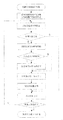
如图2所示,在上述导航控制系统的基础上,提出了巡检机器人导航控制方法,其控制流程,包括以下步骤:
步骤1机器人导航运行开始时,初始化系统内各模块,同时载入磁传感器阵列标定信息;
步骤2机器人导航运行过程中,阵列状态处理模块采集传感器阵列状态输出,并与传感器标定信息进行比较,得到当前磁传感器阵列中心相对于磁轨迹的横向偏移量Dc。在此过程中,阵列状态处理模块还负责在传感器阵列状态改变时测量状态改变之间的时间间隔ΔT;
步骤3导航控制模块综合利用阵列状态处理模块得到的当前横向偏移量Dc和状态改变时间间隔ΔT,计算得到导航控制量u,并发送至运动控制模块执行。
所述步骤1中,磁传感器阵列标定信息是在机器人导航运行前,通过执行
传感器标定步骤得到,进行标定的主要目的则是为了将各传感器阵列状态所代表的横向偏移量进行定量描述,以便后续导航控制使用。
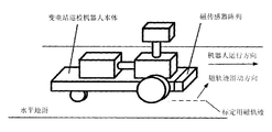
如图3所示,具体的磁传感器阵列标定的方法为:首先将机器人静止放置于水平面上,使标定用磁轨迹至于磁传感器一侧水平面;由于磁传感器阵列中传感器一般沿垂直于机器人运行方向排列,标定时需面向机器人运行的反方向,从传感器阵列的左外侧向右外侧沿水平面滑动,此过程中,将磁传感器阵列中首次检测到磁轨迹的位置设为零点,之后每当磁传感器阵列状态变化就记录当时磁轨迹位置与零点之间的距离,直至磁轨迹从右端滑出为止;最后,求标定过程得到距离数值的均值,再将以上距离值与该均值相减,从而得到传感器阵列每个状态所代表的横向偏移量。
所述步骤2中,测量传感器阵列状态改变时间间隔步骤为:
步骤2-1磁传感器阵列检测到磁轨迹时,阵列状态处理模块计时器清零,并开始计时;
步骤2-2当磁传感器阵列输出状态变化,则读取当前计时器值Tc,如果在计时器允许最大计时时间Tmax内,当前读出值Tc即为相邻状态变化时间间隔ΔT,否则将相邻状态变化时间间隔ΔT修正为计时器允许最大计时值Tmax;
步骤2-3清零计时器,并开始下一次状态变化时间间隔测量计时。
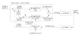
如图4所示,步骤3中导航控制量的具体计算步骤如下:
步骤3-1将从阵列状态处理模块得到的当前横向偏移量Dc与系数Kp相乘,得到横向偏移控制量Up;
步骤3-2将当前横向偏移量Dc和上一次获取的横向偏移量Dp相减,得到横向偏移变化量,之后该变化量再乘以采样控制周期Ts与状态变化时间间隔ΔT之商,从而得到横向偏移变化趋势值,最后该趋势值乘以系数Kd,得到横向
偏移变化趋势控制量Ud;
步骤3-3将上述横向偏移控制量Up与横向偏移变化趋势控制量Ud相加,即可得到最终的导航控制量U,其完整计算公式如下所示:
U=Up+Ud=Kp*Dc+Kd*(Dc-Dp)*(Ts/ΔT)
其中:Up为横向偏移控制量,Ud为横向偏移变化趋势控制量;Kp为横向偏移控制系数,Kd为横向偏移变化趋势控制系数;Dc为当前获取的横向偏移量,Dp为上一次获取的横向偏移量;Ts为系统采样控制周期,ΔT为磁传感器阵列相邻状态变化时间间隔。
本公开还提供了一种计算机可读存储介质,存储有计算机可执行指令,所述计算机可执行指令设置为执行上述实施例的变电站巡检机器人导航控制方法。
本公开还提供了一种计算机程序产品,所述计算机程序产品包括可存储在计算机可读存储介质上的计算机程序,所述计算机程序包括程序指令,当所述程序指令被计算机执行时,使所述计算机执行上述实施例的变电站巡检机器人导航控制方法。
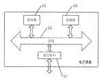
本公开还提供了一种电子设备。图5是本公开实施例提供的电子设备的结构框图。该电子设备可以包括:处理器(processor)51和存储器(memory)53,还可以包括通信接口(Communications Interface)52和总线54。其中,处理器51、通信接口52、存储器53可以通过总线54完成相互间的通信。通信接口52可以用于信息传输。处理器51可以调用存储器53中的逻辑指令,以执行上述实施例的应用程序控制方法。
此外,上述的存储器53中的逻辑指令可以通过软件功能单元的形式实现并作为独立的产品销售或使用时,可以存储在一个计算机可读取存储介质中。基
于这样的理解,本公开的技术方案可以以软件产品的形式体现出来,该计算机软件产品存储在一个存储介质中,包括若干指令用以使得一台计算机设备(可以是个人计算机,服务器,或者网络设备等)执行本公开各个实施例所述方法的全部或部分步骤。而前述的存储介质可以是非暂态存储介质,包括:U盘、移动硬盘、只读存储器(ROM,Read-Only Memory)、随机存取存储器(RAM,RandomAccess Memory)、磁碟或者光盘等各种可以存储程序代码的介质,也可以是暂态存储介质。
上述虽然结合附图对本公开的具体实施方式进行了描述,但并非对本公开保护范围的限制,所属领域技术人员应该明白,在本公开的技术方案的基础上,本领域技术人员不需要付出创造性劳动即可做出的各种修改或变形仍在本公开的保护范围以内。
本公开的变电站巡检机器人导航控制系统及方法,实现对机器人运动导致的横向偏移变化趋势进行预测并提前进行调整,改善导航控制系统中存在的导航控制输出滞后对系统稳定性造成的影响,提升机器人运行的稳定性。
Claims (12)
- 一种变电站巡检机器人导航控制系统,包括:磁传感器阵列、阵列状态处理模块、导航控制模块和运动控制模块,其中,所述磁传感器阵列,采集实际横向偏移量,将传感器阵列标定信息传输给阵列状态处理模块;所述阵列状态处理模块,连接磁传感器阵列和导航控制模块,设置为依据磁传感器阵列标定信息,得到磁传感器阵列状态所对应的横向偏移量以及状态变化时间间隔,之后发送至导航控制模块;所述导航控制模块,设置为利用当前横向偏移量和状态改变时间间隔,计算导航控制量发送至运动控制模块;所述运动控制模块执行导航控制模块的导航指令,控制巡检机器人的运动。
- 如权利要求1所述的一种变电站巡检机器人导航控制系统,其中,所述磁传感器阵列以数字开关量输出方式与阵列状态处理模块连接,阵列状态处理模块则利用数字通讯方式与导航控制模块连接,导航控制模块也通过数字通讯方式连接运动控制模块。
- 一种变电站巡检机器人导航控制方法,包括:机器人导航运行开始时,进行初始化,同时载入磁传感器阵列标定信息;机器人导航运行过程中,阵列状态处理模块采集传感器阵列状态输出,与传感器阵列标定信息进行比较,得到当前磁传感器阵列中心相对于磁轨迹的横向偏移量,阵列状态处理模块在传感器阵列状态改变时测量状态改变之间的时间间隔;导航控制模块综合利用阵列状态处理模块得到的当前横向偏移量和状态改变时间间隔,计算得到导航控制量并发送至运动控制模块执行。
- 如权利要求3所述的变电站巡检机器人导航控制方法,还包括:在机器人导航运行前,通过执行传感器标定步骤得到磁传感器阵列标定信息,所述磁 传感器阵列标定信息包括各传感器阵列状态所代表的横向偏移量。
- 如权利要求4所述的变电站巡检机器人导航控制方法,其中,通过执行传感器标定步骤得到磁传感器阵列标定信息的步骤包括:将机器人静止放置于水平面上,使磁轨迹置于磁传感器一侧水平面;磁传感器阵列中传感器沿垂直于机器人运行方向排列,标定时需面向机器人运行的反方向,从传感器阵列的左外侧向右外侧沿水平面滑动,滑动过程中,将磁传感器阵列中首次检测到磁轨迹的位置设为零点,之后每当磁传感器阵列状态变化时记录当前磁轨迹位置与零点之间的距离,直至磁轨迹从右端滑出为止;求标定过程得到距离值的均值,再将以上距离值与该均值相减,得到传感器阵列每个状态所代表的横向偏移量。
- 如权利要求3所述的变电站巡检机器人导航控制方法,其中,测量传感器阵列状态改变时间间隔步骤包括:磁传感器阵列检测到磁轨迹时,阵列状态处理模块计时器清零,并开始计时;当磁传感器阵列输出状态变化,则读取当前计时器值Tc,如果在计时器允许最大计时时间Tmax内,当前读出值Tc即为相邻状态变化时间间隔ΔT,否则将相邻状态变化时间间隔ΔT修正为计时器允许最大计时值Tmax;清零计时器,并开始下一次状态变化时间间隔测量计时。
- 如权利要求3所述的变电站巡检机器人导航控制方法,其中,计算得到导航控制量包括:将从阵列状态处理模块得到的当前横向偏移量Dc与系数Kp相乘,得到横向偏移控制量Up;将当前横向偏移量Dc和上一次获取的横向偏移量Dp相减,得到横向偏移变化量,之后该变化量再乘以采样控制周期Ts与阵列状态变化时间间隔ΔT之商,从而得到横向偏移变化趋势值,该趋势值乘以系数Kd,得到横向偏移变化 趋势控制量Ud;横向偏移控制量Up与横向偏移变化趋势控制量Ud相加,即可得到最终的导航控制量U。
- 如权利要求7所述的变电站巡检机器人导航控制方法,其中,最终的导航控制量U的计算公式为:U=Up+Ud=Kp*Dc+Kd*(Dc-Dp)*(Ts/ΔT)其中:Up为横向偏移控制量,Ud为横向偏移变化趋势控制量;Kp为横向偏移控制系数,Kd为横向偏移变化趋势控制系数;Dc为当前获取的横向偏移量,Dp为上一次获取的横向偏移量;Ts为系统采样控制周期,ΔT为磁传感器阵列相邻状态变化时间间隔。
- 如权利要求5所述的变电站巡检机器人导航控制方法,其中,所述磁传感器阵列状态为磁传感器阵列输出数字量。
- 一种非易失性存储介质,存储有计算机可执行指令,所述计算机可执行指令设置为执行权利要求3-8任一项所述的变电站巡检机器人导航控制方法。
- 一种计算机程序产品,所述计算机程序产品包括存储在非易失性计算机可读存储介质上的计算机程序,所述计算机程序包括程序指令,当所述程序指令被计算机执行时,使所述计算机执行权利要求3-8任一项所述的变电站巡检机器人导航控制方法。
- 一种电子设备,包括至少一个处理器和与所述至少一个处理器通信连接的存储器,所述存储器用于存储可被所述至少一个处理器执行的指令,所述指令被所述至少一个处理器执行时,使所述至少一个处理器执行权利要求3-8任一项所述的变电站巡检机器人导航控制方法。
Applications Claiming Priority (2)
| Application Number | Priority Date | Filing Date | Title |
|---|---|---|---|
| CN201610696719.2 | 2016-08-17 | ||
| CN201610696719.2A CN106292664B (zh) | 2016-08-17 | 2016-08-17 | 一种变电站巡检机器人导航控制系统及方法 |
Publications (1)
| Publication Number | Publication Date |
|---|---|
| WO2018032933A1 true WO2018032933A1 (zh) | 2018-02-22 |
Family
ID=57661830
Family Applications (1)
| Application Number | Title | Priority Date | Filing Date |
|---|---|---|---|
| PCT/CN2017/093788 Ceased WO2018032933A1 (zh) | 2016-08-17 | 2017-07-21 | 变电站巡检机器人导航控制系统及方法 |
Country Status (2)
| Country | Link |
|---|---|
| CN (1) | CN106292664B (zh) |
| WO (1) | WO2018032933A1 (zh) |
Cited By (21)
| Publication number | Priority date | Publication date | Assignee | Title |
|---|---|---|---|---|
| CN108638084A (zh) * | 2018-06-15 | 2018-10-12 | 浙江国自机器人技术有限公司 | 一种巡检机器人及巡检机器人的控制方法 |
| CN109204604A (zh) * | 2018-11-09 | 2019-01-15 | 云南兆讯科技有限责任公司 | 一种变电站巡检机器人辅助越障系统及方法 |
| CN110543176A (zh) * | 2019-09-20 | 2019-12-06 | 昆山富辰迪隆智能机电科技有限公司 | 一种agv小车导航方法 |
| CN110648001A (zh) * | 2019-08-14 | 2020-01-03 | 交控科技股份有限公司 | 一种轨道交通信号系统的巡检方法和系统 |
| CN111931832A (zh) * | 2020-07-30 | 2020-11-13 | 国网智能科技股份有限公司 | 一种变电站巡检设备最优数据采集方法及系统 |
| CN111983631A (zh) * | 2020-08-17 | 2020-11-24 | 云南电网有限责任公司电力科学研究院 | 一种针对狭长密闭空间的蛇形电力巡检机器人定位系统 |
| CN112092016A (zh) * | 2020-07-11 | 2020-12-18 | 广东翼景信息科技有限公司 | 一种智能变电站巡检机器人多源数据联合诊断方法 |
| CN112498368A (zh) * | 2020-11-25 | 2021-03-16 | 重庆长安汽车股份有限公司 | 自动驾驶偏移的横向轨迹规划系统及方法 |
| CN112697167A (zh) * | 2020-11-23 | 2021-04-23 | 深圳市越疆科技有限公司 | 一种红外循迹传感器的阈值调整方法及电子设备 |
| CN112763147A (zh) * | 2021-01-19 | 2021-05-07 | 国网上海市电力公司 | 一种换流站阀厅地面水迹检测系统 |
| CN113124869A (zh) * | 2019-12-30 | 2021-07-16 | 国网陕西省电力公司榆林供电公司 | 一种基于粒子滤波的变电站巡检机器人导航定位方法 |
| CN113190019A (zh) * | 2021-05-26 | 2021-07-30 | 立得空间信息技术股份有限公司 | 一种基于虚拟仿真的巡检机器人任务点布置方法及系统 |
| CN113799131A (zh) * | 2021-09-24 | 2021-12-17 | 国网山东省电力公司曲阜市供电公司 | 一种变电站巡检及维修机器人控制系统及方法 |
| CN113858231A (zh) * | 2021-10-28 | 2021-12-31 | 武汉希文科技股份有限公司 | 一种变电站轨道机器人系统的控制方法 |
| CN114018259A (zh) * | 2021-11-09 | 2022-02-08 | 国网山东省电力公司临朐县供电公司 | 一种变电站运维优化规划方法及系统 |
| CN114069838A (zh) * | 2021-10-05 | 2022-02-18 | 国网辽宁省电力有限公司电力科学研究院 | 智能传感器主动协同的变电站机器人智能巡检系统及方法 |
| CN115032341A (zh) * | 2022-06-06 | 2022-09-09 | 青岛理工大学 | 一种主动距离补偿的气体巡检平台及巡检方法 |
| CN115981364A (zh) * | 2022-12-02 | 2023-04-18 | 安徽送变电工程有限公司 | 一种巡检无人机云台控制方法及系统 |
| CN116032847A (zh) * | 2022-12-08 | 2023-04-28 | 华电重工股份有限公司 | 远程监控方法、装置、电子设备和存储介质 |
| CN121026608A (zh) * | 2025-10-28 | 2025-11-28 | 长沙拓欧科技有限公司 | 轮式剪叉式自行走作业车的自动导航测试方法及系统 |
| CN121598028A (zh) * | 2026-01-29 | 2026-03-03 | 兰州交通大学 | 高速铁路智能轨检作业机器人运行监控方法及系统 |
Families Citing this family (3)
| Publication number | Priority date | Publication date | Assignee | Title |
|---|---|---|---|---|
| CN106292664B (zh) * | 2016-08-17 | 2019-07-12 | 国网山东省电力公司电力科学研究院 | 一种变电站巡检机器人导航控制系统及方法 |
| CN107132839A (zh) * | 2017-03-16 | 2017-09-05 | 浙江工业大学 | 一种单片机机器人直线导航方法 |
| CN114200468B (zh) * | 2021-11-03 | 2024-05-17 | 南方海洋科学与工程广东省实验室(湛江) | 水下网衣巡检机器人的定位方法、系统及存储介质 |
Citations (8)
| Publication number | Priority date | Publication date | Assignee | Title |
|---|---|---|---|---|
| JP2002189519A (ja) * | 2000-12-21 | 2002-07-05 | Mitsubishi Heavy Ind Ltd | 追跡システム、及び、追跡方法 |
| CN102269995A (zh) * | 2011-06-22 | 2011-12-07 | 重庆大学 | 轮式移动机器人的变结构控制方法 |
| CN202205099U (zh) * | 2011-07-30 | 2012-04-25 | 山东鲁能智能技术有限公司 | 变电站智能巡检机器人导航和控制系统 |
| CN103292806A (zh) * | 2013-05-30 | 2013-09-11 | 成都四威高科技产业园有限公司 | 一种适合agv的磁导航系统和导航方法 |
| CN203643844U (zh) * | 2013-12-02 | 2014-06-11 | 北京工业大学 | 一种基于三电磁传感器的机器人导航装置 |
| CN104898665A (zh) * | 2015-04-16 | 2015-09-09 | 山东建筑大学 | 巡检机器人轨迹规划的方法和装置 |
| CN105180934A (zh) * | 2015-09-16 | 2015-12-23 | 成都四威高科技产业园有限公司 | 一种agv惯性导航方法 |
| CN106292664A (zh) * | 2016-08-17 | 2017-01-04 | 国网山东省电力公司电力科学研究院 | 一种变电站巡检机器人导航控制系统及方法 |
Family Cites Families (4)
| Publication number | Priority date | Publication date | Assignee | Title |
|---|---|---|---|---|
| CN100523734C (zh) * | 2006-09-28 | 2009-08-05 | 上海交通大学 | 无人驾驶车辆的磁引导装置 |
| CN102593739A (zh) * | 2012-03-27 | 2012-07-18 | 沈阳中兴电力通信有限公司 | 磁导航巡检机器人智能控制系统 |
| CN103699123B (zh) * | 2013-12-02 | 2016-05-25 | 北京工业大学 | 一种基于三个电磁传感器的机器人导航方法 |
| CN204178239U (zh) * | 2014-11-05 | 2015-02-25 | 云南电网公司昭通供电局 | 一种变电站巡检机器人导航装置 |
-
2016
- 2016-08-17 CN CN201610696719.2A patent/CN106292664B/zh active Active
-
2017
- 2017-07-21 WO PCT/CN2017/093788 patent/WO2018032933A1/zh not_active Ceased
Patent Citations (8)
| Publication number | Priority date | Publication date | Assignee | Title |
|---|---|---|---|---|
| JP2002189519A (ja) * | 2000-12-21 | 2002-07-05 | Mitsubishi Heavy Ind Ltd | 追跡システム、及び、追跡方法 |
| CN102269995A (zh) * | 2011-06-22 | 2011-12-07 | 重庆大学 | 轮式移动机器人的变结构控制方法 |
| CN202205099U (zh) * | 2011-07-30 | 2012-04-25 | 山东鲁能智能技术有限公司 | 变电站智能巡检机器人导航和控制系统 |
| CN103292806A (zh) * | 2013-05-30 | 2013-09-11 | 成都四威高科技产业园有限公司 | 一种适合agv的磁导航系统和导航方法 |
| CN203643844U (zh) * | 2013-12-02 | 2014-06-11 | 北京工业大学 | 一种基于三电磁传感器的机器人导航装置 |
| CN104898665A (zh) * | 2015-04-16 | 2015-09-09 | 山东建筑大学 | 巡检机器人轨迹规划的方法和装置 |
| CN105180934A (zh) * | 2015-09-16 | 2015-12-23 | 成都四威高科技产业园有限公司 | 一种agv惯性导航方法 |
| CN106292664A (zh) * | 2016-08-17 | 2017-01-04 | 国网山东省电力公司电力科学研究院 | 一种变电站巡检机器人导航控制系统及方法 |
Cited By (28)
| Publication number | Priority date | Publication date | Assignee | Title |
|---|---|---|---|---|
| CN108638084A (zh) * | 2018-06-15 | 2018-10-12 | 浙江国自机器人技术有限公司 | 一种巡检机器人及巡检机器人的控制方法 |
| CN109204604A (zh) * | 2018-11-09 | 2019-01-15 | 云南兆讯科技有限责任公司 | 一种变电站巡检机器人辅助越障系统及方法 |
| CN109204604B (zh) * | 2018-11-09 | 2019-09-10 | 云南兆讯科技有限责任公司 | 一种变电站巡检机器人辅助越障系统及方法 |
| CN110648001A (zh) * | 2019-08-14 | 2020-01-03 | 交控科技股份有限公司 | 一种轨道交通信号系统的巡检方法和系统 |
| CN110543176A (zh) * | 2019-09-20 | 2019-12-06 | 昆山富辰迪隆智能机电科技有限公司 | 一种agv小车导航方法 |
| CN113124869A (zh) * | 2019-12-30 | 2021-07-16 | 国网陕西省电力公司榆林供电公司 | 一种基于粒子滤波的变电站巡检机器人导航定位方法 |
| CN112092016B (zh) * | 2020-07-11 | 2024-06-07 | 广东翼景信息科技有限公司 | 一种智能变电站巡检机器人多源数据联合诊断方法 |
| CN112092016A (zh) * | 2020-07-11 | 2020-12-18 | 广东翼景信息科技有限公司 | 一种智能变电站巡检机器人多源数据联合诊断方法 |
| CN111931832A (zh) * | 2020-07-30 | 2020-11-13 | 国网智能科技股份有限公司 | 一种变电站巡检设备最优数据采集方法及系统 |
| CN111931832B (zh) * | 2020-07-30 | 2024-05-21 | 国网智能科技股份有限公司 | 一种变电站巡检设备最优数据采集方法及系统 |
| CN111983631A (zh) * | 2020-08-17 | 2020-11-24 | 云南电网有限责任公司电力科学研究院 | 一种针对狭长密闭空间的蛇形电力巡检机器人定位系统 |
| CN111983631B (zh) * | 2020-08-17 | 2023-11-21 | 云南电网有限责任公司电力科学研究院 | 一种针对狭长密闭空间的蛇形电力巡检机器人定位系统 |
| CN112697167A (zh) * | 2020-11-23 | 2021-04-23 | 深圳市越疆科技有限公司 | 一种红外循迹传感器的阈值调整方法及电子设备 |
| CN112498368A (zh) * | 2020-11-25 | 2021-03-16 | 重庆长安汽车股份有限公司 | 自动驾驶偏移的横向轨迹规划系统及方法 |
| CN112498368B (zh) * | 2020-11-25 | 2022-03-11 | 重庆长安汽车股份有限公司 | 自动驾驶偏移的横向轨迹规划系统及方法 |
| CN112763147A (zh) * | 2021-01-19 | 2021-05-07 | 国网上海市电力公司 | 一种换流站阀厅地面水迹检测系统 |
| CN113190019A (zh) * | 2021-05-26 | 2021-07-30 | 立得空间信息技术股份有限公司 | 一种基于虚拟仿真的巡检机器人任务点布置方法及系统 |
| CN113799131A (zh) * | 2021-09-24 | 2021-12-17 | 国网山东省电力公司曲阜市供电公司 | 一种变电站巡检及维修机器人控制系统及方法 |
| CN114069838B (zh) * | 2021-10-05 | 2023-09-22 | 国网辽宁省电力有限公司电力科学研究院 | 智能传感器主动协同的变电站机器人智能巡检系统及方法 |
| CN114069838A (zh) * | 2021-10-05 | 2022-02-18 | 国网辽宁省电力有限公司电力科学研究院 | 智能传感器主动协同的变电站机器人智能巡检系统及方法 |
| CN113858231A (zh) * | 2021-10-28 | 2021-12-31 | 武汉希文科技股份有限公司 | 一种变电站轨道机器人系统的控制方法 |
| CN114018259A (zh) * | 2021-11-09 | 2022-02-08 | 国网山东省电力公司临朐县供电公司 | 一种变电站运维优化规划方法及系统 |
| CN115032341A (zh) * | 2022-06-06 | 2022-09-09 | 青岛理工大学 | 一种主动距离补偿的气体巡检平台及巡检方法 |
| CN115981364A (zh) * | 2022-12-02 | 2023-04-18 | 安徽送变电工程有限公司 | 一种巡检无人机云台控制方法及系统 |
| CN116032847A (zh) * | 2022-12-08 | 2023-04-28 | 华电重工股份有限公司 | 远程监控方法、装置、电子设备和存储介质 |
| CN116032847B (zh) * | 2022-12-08 | 2026-03-27 | 华电科工股份有限公司 | 远程监控方法、装置、电子设备和存储介质 |
| CN121026608A (zh) * | 2025-10-28 | 2025-11-28 | 长沙拓欧科技有限公司 | 轮式剪叉式自行走作业车的自动导航测试方法及系统 |
| CN121598028A (zh) * | 2026-01-29 | 2026-03-03 | 兰州交通大学 | 高速铁路智能轨检作业机器人运行监控方法及系统 |
Also Published As
| Publication number | Publication date |
|---|---|
| CN106292664A (zh) | 2017-01-04 |
| CN106292664B (zh) | 2019-07-12 |
Similar Documents
| Publication | Publication Date | Title |
|---|---|---|
| WO2018032933A1 (zh) | 变电站巡检机器人导航控制系统及方法 | |
| CN108214487B (zh) | 基于双目视觉和激光雷达的机器人目标定位和抓取方法 | |
| KR102079940B1 (ko) | 마찰계수 추정 기능을 갖는 이동 로봇 및 마찰계수 추정 방법 | |
| KR101475826B1 (ko) | 백스테핑 기법을 이용한 선도 추종자 대형제어 장치, 방법 및 이동로봇 | |
| CN114115274B (zh) | 一种农用轮式拖拉机路径跟踪输出反馈控制策略 | |
| CN104062983B (zh) | 一种谐波传动的高精度位置控制系统及方法 | |
| US9952249B2 (en) | Inertia estimating method and inertia estimation apparatus of position control apparatus | |
| CN109656130B (zh) | 搬运机器人运行控制方法、装置、机器人以及存储介质 | |
| CN104964683B (zh) | 一种室内环境地图创建的闭环校正方法 | |
| CN106123922A (zh) | 基于比例微分调节的磁导航agv直行路线纠偏方法 | |
| CN112731952A (zh) | 一种机器人质心规划方法、装置、可读存储介质及机器人 | |
| US20210264177A1 (en) | Object collision prediction method and apparatus | |
| CN103472837A (zh) | 一种基于双核两轮微电脑鼠快速冲刺控制器 | |
| CN111805547A (zh) | 一种轨迹动态跟踪实现方法 | |
| CN109073390B (zh) | 一种定位方法及装置、电子设备和可读存储介质 | |
| CN109857103B (zh) | 一种自动驾驶车辆的控制方法、装置及系统 | |
| CN105241449A (zh) | 平行架构下巡检机器人视觉导航方法与系统 | |
| CN103808452B (zh) | 电动助力转向装置的零点调整方法及其调零装置 | |
| CN111800992B (zh) | 制冷设备控制方法、装置、设备及计算机可读存储介质 | |
| CN206833249U (zh) | 一种物流机器人 | |
| CN108344412A (zh) | 一种移动机器人导航系统和方法 | |
| CN120195996B (zh) | 一种打桩作业的施工坐标控制方法及系统 | |
| US20180365791A1 (en) | Control device, position control system, position control method, and recording medium | |
| CN104238558A (zh) | 一种基于单摄像头的循迹机器人直角转弯检测方法及装置 | |
| CN118123850A (zh) | 一种长柔性液压机械臂形变感知与轨迹跟踪方法及系统 |
Legal Events
| Date | Code | Title | Description |
|---|---|---|---|
| 121 | Ep: the epo has been informed by wipo that ep was designated in this application |
Ref document number: 17840908 Country of ref document: EP Kind code of ref document: A1 |
|
| NENP | Non-entry into the national phase |
Ref country code: DE |
|
| 122 | Ep: pct application non-entry in european phase |
Ref document number: 17840908 Country of ref document: EP Kind code of ref document: A1 |