WO2018030535A1 - 台座付きセンサモジュール - Google Patents
台座付きセンサモジュール Download PDFInfo
- Publication number
- WO2018030535A1 WO2018030535A1 PCT/JP2017/029212 JP2017029212W WO2018030535A1 WO 2018030535 A1 WO2018030535 A1 WO 2018030535A1 JP 2017029212 W JP2017029212 W JP 2017029212W WO 2018030535 A1 WO2018030535 A1 WO 2018030535A1
- Authority
- WO
- WIPO (PCT)
- Prior art keywords
- sensor module
- pedestal
- sensor
- unit
- bottom plate
- Prior art date
- Legal status (The legal status is an assumption and is not a legal conclusion. Google has not performed a legal analysis and makes no representation as to the accuracy of the status listed.)
- Ceased
Links
Images



Classifications
-
- B—PERFORMING OPERATIONS; TRANSPORTING
- B60—VEHICLES IN GENERAL
- B60C—VEHICLE TYRES; TYRE INFLATION; TYRE CHANGING; CONNECTING VALVES TO INFLATABLE ELASTIC BODIES IN GENERAL; DEVICES OR ARRANGEMENTS RELATED TO TYRES
- B60C19/00—Tyre parts or constructions not otherwise provided for
-
- B—PERFORMING OPERATIONS; TRANSPORTING
- B60—VEHICLES IN GENERAL
- B60C—VEHICLE TYRES; TYRE INFLATION; TYRE CHANGING; CONNECTING VALVES TO INFLATABLE ELASTIC BODIES IN GENERAL; DEVICES OR ARRANGEMENTS RELATED TO TYRES
- B60C23/00—Devices for measuring, signalling, controlling, or distributing tyre pressure or temperature, specially adapted for mounting on vehicles; Arrangement of tyre inflating devices on vehicles, e.g. of pumps or of tanks; Tyre cooling arrangements
- B60C23/02—Signalling devices actuated by tyre pressure
- B60C23/04—Signalling devices actuated by tyre pressure mounted on the wheel or tyre
Definitions
- the present invention relates to a sensor module attached to the inner surface of a tire.
- a sensor unit such as a pressure sensor, a temperature sensor, and an acceleration sensor, a sensor unit in which an amplifier and a transmitter are arranged, a power source unit including a battery or a power generation element, and a wiring unit that connects the sensor unit and the power source unit.
- a technology is known in which an integrated sensor module is mounted on the inner surface of a tire via a rubber pedestal to detect the state of the running tire, such as tire internal pressure, and to transmit the detected sensor information to the vehicle side. (For example, refer to Patent Document 1).
- the shape of the rubber pedestal is not only complicated, but the power supply unit, the sensor unit, and the wiring unit are stacked in the tire radial direction. Therefore, there was a problem that durability was not sufficient.
- the present invention has been made in view of conventional problems, and an object of the present invention is to provide a sensor module with a pedestal having a simple configuration and excellent durability.
- the present invention includes a sensor module having a power supply unit, a sensor unit, a wiring unit that connects the power supply unit and the sensor unit, and a pedestal having a bottom plate for installing the sensor module on the inner surface of a tire.
- a sensor module with a pedestal wherein the power supply unit, the sensor unit, and the wiring unit are arranged in a plane parallel to a plate surface of the bottom plate of the pedestal, and a direction perpendicular to the plate surface of the bottom plate of the pedestal
- the arrangement direction is the length direction
- the direction perpendicular to the length direction in the plane parallel to the plate surface of the base plate of the pedestal is the width direction
- the wiring portion has a length in the width direction.
- the width direction which has a recess that becomes narrower as it is farther from the power supply unit and the sensor unit at both ends, and the base is erected on the bottom plate and fits into the recess of the wiring unit A pair of It characterized by having a member.
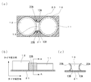
- FIG. 1 (a) to 1 (c) are diagrams showing a sensor module with a pedestal according to the present embodiment
- FIG. 2 is a view showing another example of a sensor module with a base according to the present invention
- FIG. 3 is a view showing another example of a sensor module with a base according to the present invention
- 4 (a) to 4 (c) are diagrams showing another example of a sensor module with a base according to the present invention
- 5A to 5C are diagrams showing another example of the sensor module with a pedestal according to the present invention.
- FIGS. 1A to 1C are diagrams showing the present embodiment, in which FIG. 1A is a plan view, FIG. 1B is a side view, and FIG. FIG.
- a sensor module 10G with a pedestal includes a sensor module 10 including a sensor unit 11, a power supply unit 12, and a wiring unit 13, and a pedestal 20 including a bottom plate 21 and a pair of holding members 22A and 22B. Is provided.
- the sensor module with base 10G is fixed to the inner surface of a tire (not shown) by bonding or the like.
- the bottom plate 21 of the pedestal 20 fixed to the inner surface side of the tire is formed of a rectangular plate material whose sides are parallel to the tire circumferential direction and the tire width direction, and the sensor module 10 is replaced with the pedestal 20.
- the bottom plate 21 was placed on the plate surface. That is, the sensor unit 11, the power supply unit 12, and the wiring unit 13 of the sensor module 10 are arranged in a plane parallel to the plate surface of the bottom plate 21 of the base 20.
- the tire radial direction that is a direction perpendicular to the plate surface of the bottom plate 21 of the base 20 is the vertical direction
- the tire width direction that is the arrangement direction of the sensor modules 10 that is the direction from the sensor unit 11 toward the power supply unit 12 is the length.
- the sensor unit 11 is a cylindrical member having an axis parallel to the vertical direction, and includes a pressure sensor, A sensor 11a such as a temperature sensor and an acceleration sensor, an amplifier 11b, and a transmitter 11c are accommodated.
- the power supply unit 12 is also a cylindrical member having an axis parallel to the vertical direction, and a button battery 12B is built therein.
- the wiring part 13 accommodates the power supply line 13p and the ground line 13q that connect the connection terminals 12p and 12q of the power supply part 12 and the connection terminals 11p and 11q of the sensor part 11, and has dimensions in the length direction.
- the length of the sensor module 10 was about 1/8. Moreover, in this example, as shown in FIG. 1A, the width that is the length dimension in the width direction is separated from the power supply unit 12 and the sensor unit 11 on the side surfaces 13 ⁇ / b> A and 13 ⁇ / b> B that are surfaces that intersect in the width direction. As shown in FIG. 1 (c), a concave portion is provided so that the width of the central portion in the vertical direction is narrower than the width of the end portion in the vertical direction.
- the side surfaces 13 ⁇ / b> A and 13 ⁇ / b> B of the wiring portion 13 of the sensor module 10 are supported by a pair of holding members 22 ⁇ / b> A and 22 ⁇ / b> B erected on the bottom plate 21 of the base 20.
- the sensor module 10 is gripped by the pedestal 20.
- the holding members 22A and 22B are arranged so that the interval when viewed in the vertical direction is such that the interval in the width direction is narrow at the central portion, and at the central portion in the vertical direction between the holding members 22A and 22B.
- the side surfaces 13A and 13B of the wiring portion 13 of the sensor module 10 can be fitted between the holding members 22A and 22B.
- the holding members 22A and 22B are made of, for example, a resin plate, and the distance between the holding members 22A and 22B may be set slightly smaller than the distance between the side surfaces 13A and 13B of the wiring portion 13.
- the sensor module 10 can be securely held on the base 20 by the spring effect of the resin plate.
- the arrangement direction of the sensor modules 10, which is the direction from the sensor unit 11 toward the power supply unit 12, is the tire width direction, but may be a tire circumferential direction. Or the direction which cross
- the length of the wiring part 13 was about 1/8 of the length of the sensor module 10, as shown in FIG. 2, while making the length of a wiring part long, holding member If the lengths of 22A and 22B are increased, the sensor module 10 can be gripped over a wide area, so that the sensor module 10 can be firmly gripped on the pedestal 20.
- the length of the wiring portion 13 is preferably about 2/5 or less of the length of the sensor module 10.
- the sensor module 10 can be reliably gripped by the base 20 without unnecessarily increasing the volume of the sensor module 10.
- holding member 22A, 22B was comprised from resin board, you may use a rubber member.
- the holding members 22A and 22B are rubber members, the holding members 22A and 22B may have a plate shape as shown in FIGS. 1A to 1C, but are shown in FIG. Thus, it is preferable to use a block shape. Thereby, the sensor module 10 can be reliably gripped on the base 20 by the elastic force of the rubber member.
- the length of the bottom plate 21 of the base 20 is slightly larger than the length of the holding members 22A and 22B.
- the bottom plate 21 is expanded. If the sensor unit 11 and the power supply unit 12 are also configured to be mounted on the bottom plate 21, the sensor module 10G with a pedestal can be more firmly attached to the inner surface of the tire.
- a pedestal 20 may be provided with a side wall 23 standing on the bottom plate 21 and covering the side surfaces of the power supply unit 12, the sensor unit 11, and the wiring unit 13. Good. Thereby, since the whole sensor module 10 is covered with holding members, such as rubber
- the present invention includes a sensor module having a power supply unit, a sensor unit, a wiring unit that connects the power supply unit and the sensor unit, and a pedestal having a bottom plate for installing the sensor module on the inner surface of a tire.
- a sensor module with a pedestal wherein the power supply unit, the sensor unit, and the wiring unit are arranged in a plane parallel to a plate surface of the bottom plate of the pedestal, and a direction perpendicular to the plate surface of the bottom plate of the pedestal
- the arrangement direction is the length direction
- the direction perpendicular to the length direction in the plane parallel to the plate surface of the base plate of the pedestal is the width direction
- the wiring portion has a length in the width direction.
- the width direction which has a recess that becomes narrower as it is farther from the power supply unit and the sensor unit at both ends, and the base is erected on the bottom plate and fits into the recess of the wiring unit A pair of It characterized by having a member.
- the pair of holding members are erected on the bottom plate so that the interval in the width direction becomes narrow at the center, and the wiring portion is fitted between the pair of holding members.
- the sensor module can be reliably gripped.
- the distance between the pair of holding members in the vertical center is also narrower than the distance between the vertical ends, so that the wiring portion can be firmly held between the pair of holding members.
- the length dimension and width method of the said baseplate were made larger than the length dimension and width dimension of the said sensor module, a sensor module can be stably mounted
- the pedestal further includes a side wall portion that stands on the bottom plate and covers the side surfaces of the power source portion, the sensor portion, and the wiring portion, the sensor module can be securely and stably gripped.
Landscapes
- Engineering & Computer Science (AREA)
- Mechanical Engineering (AREA)
- Tires In General (AREA)
- Measuring Fluid Pressure (AREA)
Abstract
電源部12と、センサ部11と、電源部12とセンサ部11とを接続する配線部13とを有するセンサモジュール10と、センサモジュール10をタイヤの内面に設置するため底板21を有する台座20とを備え、電源部12とセンサ部11と配線部13とを台座20の底板21の板面に平行な面内に配列し、配線部13の側面13A,13Bに、上下方向からみた幅が、電源部12とセンサ部11から離れるほど狭く、かつ、上下方向中央部の幅が、上下方向端部の幅よりも狭くなるような凹部を設け、台座20の底板21に、前記凹部と嵌合する一対の保持部材22A,22Bを立設した。
Description
本発明は、タイヤの内面に取付けられるセンサモジュールに関するものである。
従来、圧力センサ、温度センサ、加速度センサ等のセンサと増幅器及び送信器が配置されたセンサ部と、電池又は発電素子から成る電源部と、これらセンサ部と電源部とを連結する配線部とを一体化したセンサモジュールを、ゴム台座を介してタイヤの内面に装着し、タイヤ内圧などの走行中のタイヤの状態を検出するとともに、検出されたセンサ情報を車両側に送信する技術が知られている(例えば、特許文献1参照)。
しかしながら、上記構成では、ゴム台座の形状が複雑であるだけでなく、電源部とセンサ部と配線部とがタイヤ径方向に積み重なっているため、タイヤの転動時には、ゴム台座に負担がかかってしまうため、耐久性が十分ではなかった、といった問題点があった。
本発明は、従来の問題点に鑑みてなされたもので、簡単な構成で、かつ、耐久性にも優れた台座付きセンサモジュールを提供することを目的とする。
発明者は、鋭意検討の結果、電源部とセンサ部と配線部とをタイヤ周方向及びタイヤ幅方向とに平行な面内に配列するとともに、配線部に凹部を設け、この凹部を両側から台座で保持するようにすれば、簡単な構成で、センサモジュールを確実に把持できることを見出し、本発明に到ったものである。
すなわち、本発明は、電源部とセンサ部と前記電源部と前記センサ部とを接続する配線部とを有するセンサモジュールと、前記センサモジュールをタイヤの内面に設置するため底板を有する台座とを備えた台座付きセンサモジュールであって、前記電源部と前記センサ部と前記配線部とが前記台座の底板の板面に平行な面内に配列され、前記台座の底板の板面に垂直な方向を上下方向、前記配列方向を長さ方向、前記台座の底板の板面に平行な面内において前記長さ方向と直交する方向を幅方向とした時、前記配線部は、前記幅方向の長さ寸法である幅が、両端部である前記電源部とセンサ部から離れるほど狭くなる凹部を有し、前記台座が、前記底板に立設されて前記配線部の凹部と嵌合する、前記幅方向の間隔が中央部で狭い、一対の保持部材を有することを特徴とする。
すなわち、本発明は、電源部とセンサ部と前記電源部と前記センサ部とを接続する配線部とを有するセンサモジュールと、前記センサモジュールをタイヤの内面に設置するため底板を有する台座とを備えた台座付きセンサモジュールであって、前記電源部と前記センサ部と前記配線部とが前記台座の底板の板面に平行な面内に配列され、前記台座の底板の板面に垂直な方向を上下方向、前記配列方向を長さ方向、前記台座の底板の板面に平行な面内において前記長さ方向と直交する方向を幅方向とした時、前記配線部は、前記幅方向の長さ寸法である幅が、両端部である前記電源部とセンサ部から離れるほど狭くなる凹部を有し、前記台座が、前記底板に立設されて前記配線部の凹部と嵌合する、前記幅方向の間隔が中央部で狭い、一対の保持部材を有することを特徴とする。
なお、前記発明の概要は、本発明の必要な全ての特徴を列挙したものではなく、これらの特徴群のサブコンビネーションもまた、発明となり得る。
図1(a)乃至1(c)は、本実施の形態に係る台座付きセンサモジュールを示す図;
図2は、本発明による台座付きセンサモジュールの他の例を示す図;
図3は、本発明による台座付きセンサモジュールの他の例を示す図;
図4(a)乃至4(c)は、本発明による台座付きセンサモジュールの他の例を示す図;
図5(a)乃至5(c)は、本発明による台座付きセンサモジュールの他の例を示す図である。
図2は、本発明による台座付きセンサモジュールの他の例を示す図;
図3は、本発明による台座付きセンサモジュールの他の例を示す図;
図4(a)乃至4(c)は、本発明による台座付きセンサモジュールの他の例を示す図;
図5(a)乃至5(c)は、本発明による台座付きセンサモジュールの他の例を示す図である。
実施の形態
図1(a)~(c)は、本実施の形態を示す図で、(a)図は平面図、(b)図は側面図、(c)図は(b)図のA-A断面図である。
本実施の形態に係る台座付きセンサモジュール10Gは、センサ部11と電源部12と配線部13とを備えたセンサモジュール10と、底板21と一対の保持部材22A,22Bとを備えた台座20とを備える。台座付きセンサモジュール10Gは、図示しないタイヤの内面側に接着等で固定される。
本例では、タイヤの内面側に固定される台座20の底板21を、各辺がそれぞれタイヤ周方向とタイヤ幅方向とに平行な矩形状の板材から構成するとともに、センサモジュール10を、台座20の底板21の板面上に配置した。すなわち、センサモジュール10のセンサ部11と電源部12と配線部13とは、台座20の底板21の板面に平行な面内に配列される。
ここで、台座20の底板21の板面に垂直な方向であるタイヤ径方向を上下方向、センサ部11から電源部12に向かう方向であるセンサモジュール10の配列方向であるタイヤ幅方向を長さ方向、タイヤ径方向とタイヤ幅方向とに直交する方向であるタイヤ周方向を幅方向とすると、センサ部11は、上下方向に平行な軸を有する円筒状の部材で、内部に、圧力センサ、温度センサ、加速度センサ等のセンサ11aと増幅器11bと送信器11cとが収納されている。
電源部12も、上下方向に平行な軸を有する円筒状の部材で、内部にはボタン電池12Bが内蔵されている。
一方、配線部13は、電源部12の接続端子12p,12qとセンサ部11の接続端子11p,11qとを接続する電源線13p及びアース線13qを収納するもので、長さ方向の寸法として、センサモジュール10の長さ寸法の約1/8とした。
また、本例では、幅方向に交差する面である側面13A,13Bに、図1(a)に示すように、幅方向の長さ寸法である幅が、電源部12とセンサ部11から離れるほど狭く、かつ、図1(c)に示すように、上下方向中央部の幅が、上下方向端部の幅よりも狭くなるような凹部を設けた。
図1(a)~(c)は、本実施の形態を示す図で、(a)図は平面図、(b)図は側面図、(c)図は(b)図のA-A断面図である。
本実施の形態に係る台座付きセンサモジュール10Gは、センサ部11と電源部12と配線部13とを備えたセンサモジュール10と、底板21と一対の保持部材22A,22Bとを備えた台座20とを備える。台座付きセンサモジュール10Gは、図示しないタイヤの内面側に接着等で固定される。
本例では、タイヤの内面側に固定される台座20の底板21を、各辺がそれぞれタイヤ周方向とタイヤ幅方向とに平行な矩形状の板材から構成するとともに、センサモジュール10を、台座20の底板21の板面上に配置した。すなわち、センサモジュール10のセンサ部11と電源部12と配線部13とは、台座20の底板21の板面に平行な面内に配列される。
ここで、台座20の底板21の板面に垂直な方向であるタイヤ径方向を上下方向、センサ部11から電源部12に向かう方向であるセンサモジュール10の配列方向であるタイヤ幅方向を長さ方向、タイヤ径方向とタイヤ幅方向とに直交する方向であるタイヤ周方向を幅方向とすると、センサ部11は、上下方向に平行な軸を有する円筒状の部材で、内部に、圧力センサ、温度センサ、加速度センサ等のセンサ11aと増幅器11bと送信器11cとが収納されている。
電源部12も、上下方向に平行な軸を有する円筒状の部材で、内部にはボタン電池12Bが内蔵されている。
一方、配線部13は、電源部12の接続端子12p,12qとセンサ部11の接続端子11p,11qとを接続する電源線13p及びアース線13qを収納するもので、長さ方向の寸法として、センサモジュール10の長さ寸法の約1/8とした。
また、本例では、幅方向に交差する面である側面13A,13Bに、図1(a)に示すように、幅方向の長さ寸法である幅が、電源部12とセンサ部11から離れるほど狭く、かつ、図1(c)に示すように、上下方向中央部の幅が、上下方向端部の幅よりも狭くなるような凹部を設けた。
本例では、図1(a),(c)に示すように、センサモジュール10の配線部13の側面13A,13Bを、台座20の底板21に立設された一対の保持部材22A,22Bにより保持することで、センサモジュール10を台座20により把持するようにしている。
具体的には、保持部材22A,22Bを、上下方向から見た時の間隔が、幅方向の間隔が中央部で狭くなるように配置するとともに、保持部材22A,22B間の上下方向中央部の距離が上下方向端部の距離よりも狭くすることで、保持部材22A,22B間に、センサモジュール10の配線部13の側面13A,13Bを嵌合することができる。
このとき、保持部材22A,22Bを、例えば、樹脂製の板から構成するとともに、保持部材22A,22B間の距離を、配線部13の側面13A,13B間の距離よりも若干狭く設定しておけば、樹脂板のバネ効果により、センサモジュール10を台座20に確実に把持することができる。
具体的には、保持部材22A,22Bを、上下方向から見た時の間隔が、幅方向の間隔が中央部で狭くなるように配置するとともに、保持部材22A,22B間の上下方向中央部の距離が上下方向端部の距離よりも狭くすることで、保持部材22A,22B間に、センサモジュール10の配線部13の側面13A,13Bを嵌合することができる。
このとき、保持部材22A,22Bを、例えば、樹脂製の板から構成するとともに、保持部材22A,22B間の距離を、配線部13の側面13A,13B間の距離よりも若干狭く設定しておけば、樹脂板のバネ効果により、センサモジュール10を台座20に確実に把持することができる。
以上、本発明を実施の形態及び実施例を用いて説明したが、本発明の技術的範囲は前記実施の形態に記載の範囲には限定されない。前記実施の形態に、多様な変更または改良を加えることが可能であることが当業者にも明らかである。そのような変更または改良を加えた形態も本発明の技術的範囲に含まれ得ることが、特許請求の範囲から明らかである。
例えば、前記実施の形態では、センサ部11から電源部12に向かう方向であるセンサモジュール10の配列方向をタイヤ幅方向としたが、タイヤ周方向であってもよい。あるいは、タイヤ周方向とタイヤ幅方向とに交差する方向であってもよい。
また、前記実施の形態では、配線部13の長さを、センサモジュール10の長さの約1/8としたが、図2に示すように、配線部の長さを長くするとともに、保持部材22A,22Bの長さを長くすれば、センサモジュール10を広い面積で把持できるので、センサモジュール10を台座20に強固に把持することができる。
なお、配線部13の長さとしては、センサモジュール10の長さの約2/5以下とすることが好ましい。これにより、センサモジュール10の体積を不要に大きくすることなく、センサモジュール10を台座20に確実に把持することができる。
また、前記実施の形態では、保持部材22A,22Bを樹脂製の板から構成したが、ゴム部材を用いてもよい。保持部材22A,22Bをゴム部材とした場合の、保持部材22A,22Bの形状としては、図1(a)~(c)に示すように、板状であってもよいが、図3に示すように、ブロック状とすることが好ましい。これにより、ゴム部材の弾性力でセンサモジュール10を台座20に確実に把持することができる。
また、前記実施の形態では、配線部13の長さを、センサモジュール10の長さの約1/8としたが、図2に示すように、配線部の長さを長くするとともに、保持部材22A,22Bの長さを長くすれば、センサモジュール10を広い面積で把持できるので、センサモジュール10を台座20に強固に把持することができる。
なお、配線部13の長さとしては、センサモジュール10の長さの約2/5以下とすることが好ましい。これにより、センサモジュール10の体積を不要に大きくすることなく、センサモジュール10を台座20に確実に把持することができる。
また、前記実施の形態では、保持部材22A,22Bを樹脂製の板から構成したが、ゴム部材を用いてもよい。保持部材22A,22Bをゴム部材とした場合の、保持部材22A,22Bの形状としては、図1(a)~(c)に示すように、板状であってもよいが、図3に示すように、ブロック状とすることが好ましい。これにより、ゴム部材の弾性力でセンサモジュール10を台座20に確実に把持することができる。
また、前記実施の形態では、台座20の底板21の長さを保持部材22A,22Bの長さよりも若干広くしたが、図4(a)~(c)に示すように、底板21を広げて、センサ部11と電源部12とについても、底板21上に搭載する構成とすれば、台座付きセンサモジュール10Gを、タイヤの内面により強固に取付けることができる。
あるいは、図5(a)~(c)に示すように、台座20に、底板21に立設されて、電源部12とセンサ部11と配線部13の側面を覆う側壁部23を設けてもよい。これにより、センサモジュール10全体がゴムなどの保持部材で覆われるので、センサモジュール10と台座20とは一体化される。したがって、センサモジュール10を確実にかつ安定して把持することができる。
あるいは、図5(a)~(c)に示すように、台座20に、底板21に立設されて、電源部12とセンサ部11と配線部13の側面を覆う側壁部23を設けてもよい。これにより、センサモジュール10全体がゴムなどの保持部材で覆われるので、センサモジュール10と台座20とは一体化される。したがって、センサモジュール10を確実にかつ安定して把持することができる。
以上、本発明を実施の形態及び実施例を用いて説明したが、まとめると次のように記述できる。すなわち、本発明は、電源部とセンサ部と前記電源部と前記センサ部とを接続する配線部とを有するセンサモジュールと、前記センサモジュールをタイヤの内面に設置するため底板を有する台座とを備えた台座付きセンサモジュールであって、前記電源部と前記センサ部と前記配線部とが前記台座の底板の板面に平行な面内に配列され、前記台座の底板の板面に垂直な方向を上下方向、前記配列方向を長さ方向、前記台座の底板の板面に平行な面内において前記長さ方向と直交する方向を幅方向とした時、前記配線部は、前記幅方向の長さ寸法である幅が、両端部である前記電源部とセンサ部から離れるほど狭くなる凹部を有し、前記台座が、前記底板に立設されて前記配線部の凹部と嵌合する、前記幅方向の間隔が中央部で狭い、一対の保持部材を有することを特徴とする。
このように、幅方向の間隔が中央部で狭くなるように、一対の保持部材を底板に立設し、この一対の保持部材の間に配線部を嵌合させた。本構成で、センサモジュールを確実に把持することができる。
更に、前記一対の保持部材間の上下方向中央部の距離についても、上下方向端部の距離よりも狭くしたので、配線部を一対の保持部材の間に強固に保持することができる。
また、前記底板の長さ寸法及び幅法を、前記センサモジュールの長さ寸法及び幅寸法よりも大きくしたので、センサモジュールをタイヤ内面に安定して装着することができる。
また、前記台座に、前記底板に立設されて、前記電源部と前記センサ部と前記配線部の側面を覆う側壁部を更に備えたので、センサモジュールを確実にかつ安定して把持できる。
このように、幅方向の間隔が中央部で狭くなるように、一対の保持部材を底板に立設し、この一対の保持部材の間に配線部を嵌合させた。本構成で、センサモジュールを確実に把持することができる。
更に、前記一対の保持部材間の上下方向中央部の距離についても、上下方向端部の距離よりも狭くしたので、配線部を一対の保持部材の間に強固に保持することができる。
また、前記底板の長さ寸法及び幅法を、前記センサモジュールの長さ寸法及び幅寸法よりも大きくしたので、センサモジュールをタイヤ内面に安定して装着することができる。
また、前記台座に、前記底板に立設されて、前記電源部と前記センサ部と前記配線部の側面を覆う側壁部を更に備えたので、センサモジュールを確実にかつ安定して把持できる。
10G 台座付きセンサモジュール、10 センサモジュール、
11 センサ部、12 電源部、12B ボタン電池、
13 配線部、13A,13B 配線部の側面、20 台座、21 底板、
22A,22B,23 側壁部。
11 センサ部、12 電源部、12B ボタン電池、
13 配線部、13A,13B 配線部の側面、20 台座、21 底板、
22A,22B,23 側壁部。
Claims (4)
- 電源部とセンサ部と前記電源部と前記センサ部とを接続する配線部とを有するセンサモジュールと、前記センサモジュールをタイヤの内面に設置するため底板を有する台座とを備えた台座付きセンサモジュールであって、
前記電源部と前記センサ部と前記配線部とが前記台座の底板の板面に平行な面内に配列され、
前記台座の底板の板面に垂直な方向を上下方向、
前記配列方向を長さ方向、
前記台座の底板の板面に平行な面内において前記長さ方向と直交する方向を幅方向とした時、
前記配線部は、
前記幅方向の長さ寸法である幅が、両端部である前記電源部とセンサ部から離れるほど狭くなる凹部を有し、
前記台座が、
前記底板に立設されて前記配線部の凹部と嵌合する、
前記幅方向の間隔が中央部で狭い、一対の保持部材を有することを特徴とする台座付きセンサモジュール。 - 前記一対の保持部材間の上下方向中央部の距離が上下方向端部の距離よりも狭いことを特徴とする請求項1に記載の台座付きセンサモジュール。
- 前記底板の長さ寸法及び幅寸法が、前記センサモジュールの長さ寸法及び幅寸法よりも大きいことを特徴とする請求項1または請求項2に記載の台座付きセンサモジュール。
- 前記台座は、
前記底板に立設されて、前記電源部と前記センサ部と前記配線部の側面を覆う側壁部を更に備えることを特徴とする請求項3に記載の台座付きセンサモジュール。
Applications Claiming Priority (2)
| Application Number | Priority Date | Filing Date | Title |
|---|---|---|---|
| JP2016158037A JP2018024352A (ja) | 2016-08-10 | 2016-08-10 | 台座付きセンサモジュール |
| JP2016-158037 | 2016-08-10 |
Publications (1)
| Publication Number | Publication Date |
|---|---|
| WO2018030535A1 true WO2018030535A1 (ja) | 2018-02-15 |
Family
ID=61162841
Family Applications (1)
| Application Number | Title | Priority Date | Filing Date |
|---|---|---|---|
| PCT/JP2017/029212 Ceased WO2018030535A1 (ja) | 2016-08-10 | 2017-08-10 | 台座付きセンサモジュール |
Country Status (2)
| Country | Link |
|---|---|
| JP (1) | JP2018024352A (ja) |
| WO (1) | WO2018030535A1 (ja) |
Cited By (1)
| Publication number | Priority date | Publication date | Assignee | Title |
|---|---|---|---|---|
| US12459309B2 (en) | 2018-07-24 | 2025-11-04 | The Yokohama Rubber Co., Ltd. | Pneumatic tire |
Families Citing this family (1)
| Publication number | Priority date | Publication date | Assignee | Title |
|---|---|---|---|---|
| WO2020022159A1 (ja) * | 2018-07-24 | 2020-01-30 | 横浜ゴム株式会社 | 空気入りタイヤ |
Citations (5)
| Publication number | Priority date | Publication date | Assignee | Title |
|---|---|---|---|---|
| JP2006240598A (ja) * | 2005-03-07 | 2006-09-14 | Bridgestone Corp | モジュール取付用パッチ、及び、このモジュール取付用パッチを有する空気入りタイヤ |
| JP2012245888A (ja) * | 2011-05-27 | 2012-12-13 | Bridgestone Corp | 取付構造体 |
| JP2013014201A (ja) * | 2011-07-01 | 2013-01-24 | Bridgestone Corp | 取付構造体 |
| JP2015160512A (ja) * | 2014-02-27 | 2015-09-07 | 株式会社ブリヂストン | 機能部品取付台座、及び、タイヤ |
| JP2016022868A (ja) * | 2014-07-23 | 2016-02-08 | 横浜ゴム株式会社 | 空気入りタイヤ |
-
2016
- 2016-08-10 JP JP2016158037A patent/JP2018024352A/ja active Pending
-
2017
- 2017-08-10 WO PCT/JP2017/029212 patent/WO2018030535A1/ja not_active Ceased
Patent Citations (5)
| Publication number | Priority date | Publication date | Assignee | Title |
|---|---|---|---|---|
| JP2006240598A (ja) * | 2005-03-07 | 2006-09-14 | Bridgestone Corp | モジュール取付用パッチ、及び、このモジュール取付用パッチを有する空気入りタイヤ |
| JP2012245888A (ja) * | 2011-05-27 | 2012-12-13 | Bridgestone Corp | 取付構造体 |
| JP2013014201A (ja) * | 2011-07-01 | 2013-01-24 | Bridgestone Corp | 取付構造体 |
| JP2015160512A (ja) * | 2014-02-27 | 2015-09-07 | 株式会社ブリヂストン | 機能部品取付台座、及び、タイヤ |
| JP2016022868A (ja) * | 2014-07-23 | 2016-02-08 | 横浜ゴム株式会社 | 空気入りタイヤ |
Cited By (1)
| Publication number | Priority date | Publication date | Assignee | Title |
|---|---|---|---|---|
| US12459309B2 (en) | 2018-07-24 | 2025-11-04 | The Yokohama Rubber Co., Ltd. | Pneumatic tire |
Also Published As
| Publication number | Publication date |
|---|---|
| JP2018024352A (ja) | 2018-02-15 |
Similar Documents
| Publication | Publication Date | Title |
|---|---|---|
| USD852753S1 (en) | Electrical connector housing | |
| USD754638S1 (en) | Ear cushion for earphone assembly | |
| JP5462332B2 (ja) | 超音波センサー装置 | |
| JP2011101010A5 (ja) | ||
| US10397718B2 (en) | Vibration diaphragm and manufacturing method thereof | |
| JP2013222931A5 (ja) | ||
| USD915969S1 (en) | Module for passenger service unit | |
| WO2018030535A1 (ja) | 台座付きセンサモジュール | |
| JP5938673B2 (ja) | 超音波センサ | |
| JP2019516990A5 (ja) | ||
| USD581920S1 (en) | Vehicle media hub | |
| JP6655816B2 (ja) | 車載撮像装置 | |
| TWI607913B (zh) | Axle box device and temperature detection device with temperature sensor unit attached to a trolley for railway vehicles | |
| CN109641491B (zh) | 传感器壳体 | |
| WO2017195596A1 (ja) | センサの取付構造 | |
| JP2018065494A (ja) | タイヤ情報取得装置及びゴム台座付きタイヤ情報取得装置 | |
| WO2014051313A3 (ko) | 압력센서 | |
| JP2013182664A5 (ja) | ||
| USD626381S1 (en) | Portable caddy | |
| US20160013681A1 (en) | Multi-function attachment | |
| CN110658302A (zh) | 氮氧传感器和带有防水透气结构的壳体 | |
| CN205946167U (zh) | 双指向拾音硅麦克风 | |
| JP2010538558A5 (ja) | ||
| JP6271924B2 (ja) | コネクタ装置、及び、接続方法 | |
| US9272493B2 (en) | Stamping head used for pressing anisotropic conductive film onto ceramic substrate |
Legal Events
| Date | Code | Title | Description |
|---|---|---|---|
| 121 | Ep: the epo has been informed by wipo that ep was designated in this application |
Ref document number: 17839599 Country of ref document: EP Kind code of ref document: A1 |
|
| NENP | Non-entry into the national phase |
Ref country code: DE |
|
| 122 | Ep: pct application non-entry in european phase |
Ref document number: 17839599 Country of ref document: EP Kind code of ref document: A1 |