WO2018030242A2 - Système à caméras multiples, caméra, procédé de traitement de caméra, appareil de confirmation et procédé de traitement d'appareil de confirmation - Google Patents
Système à caméras multiples, caméra, procédé de traitement de caméra, appareil de confirmation et procédé de traitement d'appareil de confirmation Download PDFInfo
- Publication number
- WO2018030242A2 WO2018030242A2 PCT/JP2017/028118 JP2017028118W WO2018030242A2 WO 2018030242 A2 WO2018030242 A2 WO 2018030242A2 JP 2017028118 W JP2017028118 W JP 2017028118W WO 2018030242 A2 WO2018030242 A2 WO 2018030242A2
- Authority
- WO
- WIPO (PCT)
- Prior art keywords
- video
- camera apparatus
- recording
- camera
- counter
- Prior art date
Links
Images


Classifications
-
- H—ELECTRICITY
- H04—ELECTRIC COMMUNICATION TECHNIQUE
- H04N—PICTORIAL COMMUNICATION, e.g. TELEVISION
- H04N5/00—Details of television systems
- H04N5/222—Studio circuitry; Studio devices; Studio equipment
- H04N5/262—Studio circuits, e.g. for mixing, switching-over, change of character of image, other special effects ; Cameras specially adapted for the electronic generation of special effects
-
- H—ELECTRICITY
- H04—ELECTRIC COMMUNICATION TECHNIQUE
- H04N—PICTORIAL COMMUNICATION, e.g. TELEVISION
- H04N23/00—Cameras or camera modules comprising electronic image sensors; Control thereof
- H04N23/60—Control of cameras or camera modules
- H04N23/68—Control of cameras or camera modules for stable pick-up of the scene, e.g. compensating for camera body vibrations
- H04N23/681—Motion detection
-
- H—ELECTRICITY
- H04—ELECTRIC COMMUNICATION TECHNIQUE
- H04N—PICTORIAL COMMUNICATION, e.g. TELEVISION
- H04N21/00—Selective content distribution, e.g. interactive television or video on demand [VOD]
- H04N21/20—Servers specifically adapted for the distribution of content, e.g. VOD servers; Operations thereof
- H04N21/21—Server components or server architectures
- H04N21/218—Source of audio or video content, e.g. local disk arrays
- H04N21/21805—Source of audio or video content, e.g. local disk arrays enabling multiple viewpoints, e.g. using a plurality of cameras
-
- H—ELECTRICITY
- H04—ELECTRIC COMMUNICATION TECHNIQUE
- H04N—PICTORIAL COMMUNICATION, e.g. TELEVISION
- H04N23/00—Cameras or camera modules comprising electronic image sensors; Control thereof
- H04N23/50—Constructional details
-
- H—ELECTRICITY
- H04—ELECTRIC COMMUNICATION TECHNIQUE
- H04N—PICTORIAL COMMUNICATION, e.g. TELEVISION
- H04N23/00—Cameras or camera modules comprising electronic image sensors; Control thereof
- H04N23/60—Control of cameras or camera modules
- H04N23/66—Remote control of cameras or camera parts, e.g. by remote control devices
- H04N23/661—Transmitting camera control signals through networks, e.g. control via the Internet
- H04N23/662—Transmitting camera control signals through networks, e.g. control via the Internet by using master/slave camera arrangements for affecting the control of camera image capture, e.g. placing the camera in a desirable condition to capture a desired image
-
- H—ELECTRICITY
- H04—ELECTRIC COMMUNICATION TECHNIQUE
- H04N—PICTORIAL COMMUNICATION, e.g. TELEVISION
- H04N23/00—Cameras or camera modules comprising electronic image sensors; Control thereof
- H04N23/90—Arrangement of cameras or camera modules, e.g. multiple cameras in TV studios or sports stadiums
-
- H—ELECTRICITY
- H04—ELECTRIC COMMUNICATION TECHNIQUE
- H04N—PICTORIAL COMMUNICATION, e.g. TELEVISION
- H04N5/00—Details of television systems
- H04N5/76—Television signal recording
- H04N5/765—Interface circuits between an apparatus for recording and another apparatus
- H04N5/77—Interface circuits between an apparatus for recording and another apparatus between a recording apparatus and a television camera
-
- H—ELECTRICITY
- H04—ELECTRIC COMMUNICATION TECHNIQUE
- H04N—PICTORIAL COMMUNICATION, e.g. TELEVISION
- H04N9/00—Details of colour television systems
- H04N9/79—Processing of colour television signals in connection with recording
- H04N9/80—Transformation of the television signal for recording, e.g. modulation, frequency changing; Inverse transformation for playback
- H04N9/82—Transformation of the television signal for recording, e.g. modulation, frequency changing; Inverse transformation for playback the individual colour picture signal components being recorded simultaneously only
- H04N9/8205—Transformation of the television signal for recording, e.g. modulation, frequency changing; Inverse transformation for playback the individual colour picture signal components being recorded simultaneously only involving the multiplexing of an additional signal and the colour video signal
Definitions
- the present technology relates to a multi-camera system, a camera, a processing method of the camera, a confirmation apparatus, and a processing method of the confirmation apparatus.
- PTL 1 discloses a technology in which a plurality of cameras are used to accurately judge an-order-of-arrival of a footrace.
- PTL 1 fails to disclose a technology of recording and immediately reproducing all moving images from a start to a goal.
- An information processing apparatus that includes a communication interface and processing circuitry.
- the processing circuitry configured to transmit a start instruction to a first camera apparatus and a second camera apparatus.
- the start instruction causes the first camera apparatus to start incrementing a first counter and the second camera apparatus to start incrementing a second counter for a video recording time period.
- the processing circuitry configured to receive, from the first camera apparatus, a first recording-start frame identifier that indicates a value of the first counter when recording of a first video by the first camera apparatus starts within the video recording time period and receive, from the first camera apparatus, a second recording-end frame identifier that indicates the value of the second counter when recording of the first video by the first camera apparatus stops within the video recording time period.
- the processing circuitry configured to receive, from the second camera apparatus, a first recording-start frame identifier that identifies a value of the second counter when recording of a second video by the second camera apparatus starts within the video recording time period and receive, from the second camera apparatus, a second recording-end frame identifier that identifies the value of the second counter when recording of the second video by the second camera apparatus stops within the video recording time period.
- the first video is associated with frame identifiers that indicate the values of the first of the first camera apparatus during the recording of the first video.
- the second video is associated with frame identifiers that indicate the values of the second counter by the second camera apparatus during the recording to the second video.
- a system including a first camera apparatus, a second camera apparatus, and an information processing apparatus.
- the information processing apparatus includes a communication interface and processing circuitry configured to transmit a start instruction to the first camera apparatus and the second camera apparatus.
- the start instruction causing the first camera apparatus to start incrementing a first counter and the second camera apparatus to start incrementing a second counter for a video recording time period.
- the processing circuitry is configured to receive, from the first camera apparatus, a first recording-start frame identifier that indicates a value of the first counter when recording of a first video by the first camera apparatus starts within the video recording time period and receive, from the first camera apparatus, a second recording-end frame identifier that indicates the value of the second counter when recording of the first video by the first camera apparatus stops within the video recording time period.
- the processing circuitry configured to receive, from the second camera apparatus, a first recording-start frame identifier that identifies a value of the second counter when recording of a second video by the second camera apparatus starts within the video recording time period and receive, from the second camera apparatus, a second recording-end frame identifier that identifies the value of the second counter when recording of the second video by the second camera apparatus stops within the video recording time period.
- the first video is associated with frame identifiers that indicate the values of the first of the first camera apparatus during the recording of the first video.
- the second video is associated with frame identifiers that indicate the values of the second counter by the second camera apparatus during the recording to the second video.
- a non-transitory computer-readable medium storing instructions which when executed by a computer cause the computer to perform a method for receiving recording-start frame and recording-end frame identifiers, the method including transmitting a start instruction to a first camera apparatus and a second camera apparatus.
- the start instruction causes the first camera apparatus to start incrementing a first counter and the second camera apparatus to start incrementing a second counter for a video recording time period.
- the method includes receiving, from the first camera apparatus, a first recording-start frame identifier that indicates a value of the first counter when recording of a first video by the first camera apparatus starts within the video recording time period.
- the method includes receiving, from the first camera apparatus, a second recording-end frame identifier that indicates the value of the second counter when recording of the first video by the first camera apparatus stops within the video recording time period.
- the method includes receiving, from the second camera apparatus, a first recording-start frame identifier that identifies a value of the second counter when recording of a second video by the second camera apparatus starts within the video recording time period.
- the method includes receiving, from the second camera apparatus, a second recording-end frame identifier that identifies the value of the second counter when recording of the second video by the second camera apparatus stops within the video recording time period.
- the first video is associated with frame identifiers that indicate the values of the first of the first camera apparatus during the recording of the first video.
- the second video is associated with frame identifiers that indicate the values of the second counter by the second camera apparatus during the recording to the second video.
- the user can confirm well moving images of moving objects captured sequentially by a plurality of cameras. It should be noted that the effects described in the present specification are merely illustrative and are not limitative, and may have additive effects.
- Fig. 1 is a block diagram showing a configuration example of a multi-camera system according to an embodiment of the present technology.
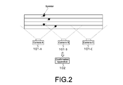
- Fig. 2 is a diagram showing an installation status of a plurality of cameras.
- Fig. 3 is a block diagram showing a configuration example of the camera.
- Fig. 4 is a block diagram showing a configuration example of a confirmation apparatus.
- Fig. 5 is a diagram showing an example that each camera counts frame numbers and records frames.
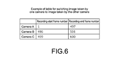
- Fig. 6 is a diagram showing an example that a table for switching an image taken by one camera to an image taken by another camera.
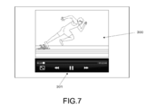
- Fig. 7 is a diagram showing an example of a screen for reproducing images (moving image content) captured by multiple cameras and displayed on a panel of the confirmation apparatus.
- Fig. 1 is a block diagram showing a configuration example of a multi-camera system according to an embodiment of the present technology.
- Fig. 2 is a diagram showing an installation status of a plurality of cameras.
- Fig. 3
- FIG. 8 is a diagram showing a communication sequence example between the confirmation apparatus and each camera at the time of the reproduction.
- Fig. 9A and Fig. 9B show another examples of the table for switching an image taken by one camera to an image taken by another camera.
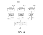
- Fig. 10 is a block diagram showing another configuration example of the multi-camera system.
- Fig. 11 is a block diagram showing another configuration example of the multi-camera system.
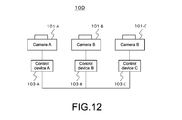
- Fig. 12 is a block diagram showing another configuration example of the multi-camera system.
- FIG. 1 shows a configuration example of a multi-camera system 10A according to an embodiment.
- the multi-camera system 10A includes a plurality of, here, three cameras (video cameras), i.e., a camera (camera A) 101-A, a camera (camera B) 101-B, and a camera (camera C) 101-C.
- the multi-camera system 10A includes a confirmation apparatus 102, which is a mobile terminal such as a smartphone and a tablet, a personal computer, or the like.
- the cameras 101-A, 101-B, and 101-C and the confirmation apparatus 102 are connected via a wired or wireless LAN.
- the confirmation apparatus 102 functions as a master device
- the cameras 101-A, 101-B, and 101-C each functions as a slave device.
- Fig. 2 shows an installation status of the cameras 101-A, 101-B, and 101-C.
- the cameras 101-A, 101-B, and 101-C are arranged so as to capture images of ranges, respectively, the ranges being obtained by dividing a range in which the moving object moves linearly, for example, a 100 m sprinter runs a straight course.
- the respective cameras 101-A, 101-B, and 101-C are arranged side by side along the course at intervals. In this manner, the cameras 101-A, 101-B, and 101-C can capture all the images of the race from the beginning to the end. In this case, the image capturing ranges of one camera and the next camera are slightly overlapped.
- the confirmation apparatus 102 causes (triggers) each camera to start and stop capturing an image in response to a user's operation.
- the confirmation apparatus 102 i.e., the master device, issues a trigger signal (command) to start or stop capturing an image to each camera.
- Each camera receives the trigger signal via a control interface (control I/F), which is configured to perform communication, and operates in response to the instruction.
- control I/F control interface
- the control interface of each camera is built in the camera.
- the confirmation apparatus 102 includes a panel (display). After capturing an image, a user can check the image captured by each camera on the panel.
- the cameras 101-A, 101-B, and 101-C each includes an imager and a memory that writes image data obtained by capturing an image by the imager.
- the image data of each frame of a period, in which a moving object is present in the image data, out of image data captured by the imager (frame rate of 60 Hz, for example) is intraframe-compressed, i.e., compressed in JPEG format in this embodiment, and the compressed data is written into the memory.
- each of the cameras 101-A, 101-B, and 101-C receives a start trigger signal from the confirmation apparatus 102, each of the cameras 101-A, 101-B, and 101-C counts frame numbers from a frame corresponding to a timing of receiving the start trigger signal.
- the frame number of the first frame is denoted as "1"
- the frame numbers of the subsequent frames are successively incremented.
- the image data written into the memory of each of the cameras 101-A, 101-B, and 101-C is in relation to the frame numbers.
- the image data of each frame is loop-recorded in the memory for at least a period, in which the moving object is present in the image capturing range of the imager, or longer.
- the image data of each frame may not necessarily be loop-recorded.
- the image data of each frame may be encoded, e.g., Advanced Video Coded (AVC), and the encoded data may be written into the memory.
- AVC Advanced Video Coded
- Each of the cameras 101-A, 101-B, and 101-C sends information on the frame numbers in relation to the image data of each frame written into the memory to the confirmation apparatus 102.
- each of the cameras 101-A, 101-B, and 101-C receives an end trigger signal from the confirmation apparatus 102, each of the cameras 101-A, 101-B, and 101-C stops a writing (recording) operation into the memory (an image-capturing operation is not necessarily stopped, but may be stopped).
- each of the cameras 101-A, 101-B, and 101-C receives a transfer request including a frame number from the confirmation apparatus 102, each of the cameras 101-A, 101-B, and 101-C reads the image data of the frame specified by the frame number from the memory, and transfers the image data to the confirmation apparatus 102.
- the confirmation apparatus 102 sends the start trigger signal to each camera in response to a user's operation to start capturing an image.
- the confirmation apparatus 102 sends the end trigger signal to each camera in response to a user's operation to stop capturing an image.
- the confirmation apparatus 102 includes an operation part configured to operate a position of a frame to be reproduced. The user operates the position of a frame to be reproduced by using the operation part.
- the confirmation apparatus 102 When the confirmation apparatus 102 reproduces a frame image of a predetermined frame number, the confirmation apparatus 102 selectively sends a transfer request including the frame number to a camera that has the image data of the frame. In this case, the confirmation apparatus 102 selects the camera to send the transfer request on the basis of the information on the frame number in relation to the image data of the frame written into the memory sent from each of the plurality of cameras.
- the confirmation apparatus 102 receives the image data of the frame having the specified frame number transferred from the camera, to which the confirmation apparatus 102 sends the transfer request as described above, and displays an image of the image data on the panel (display). In this case, the confirmation apparatus 102 sends successively the transfer requests including the successive frame numbers, and receives the image data of the respective successive frames to thereby reproduce the moving images.
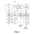
- FIG. 3 shows a configuration example of the camera 101 (101-A, 101-B, and 101-C).
- the camera 101 includes a CPU 111, a memory 112, an imager/lens 113, a camera signal processing unit 114, and a codec processing unit 115. Further, the camera 101 includes a panel processing unit 116, a panel 117, a wired communication processing unit 118, a wired LAN terminal 119, a wireless communication processing unit 120, and an antenna 121.
- the CPU 111 controls operation of components of the camera 101.
- the memory 112 stores control software and data, and constitutes a work area of the CPU 111 and the like. In addition, the memory 112 constitutes the frame buffer that loop-records the captured image data.
- the imager/lens 113 includes an image capture lens and an imager, captures an image of an object, and obtains an image capture signal.
- the camera signal processing unit 114 processes the image capture signal obtained by the imager/lens 113, and generates image data (captured image data) corresponding to the object.
- the codec processing unit 115 JPEG-compresses the image data of each frame obtained by the camera signal processing unit 114.
- the image data of each frame is loop-recorded in the frame buffer of the memory 112 for a period, in which the moving object is present in the image data.
- the CPU 111 performs a movement detection processing on the captured image data, and detects the presence of the moving object.
- the panel processing unit 116 drives a panel 117 on the basis of the image data obtained by the camera signal processing unit 114, and displays a captured image on the panel 117.
- the panel 117 includes an LCD, an organic EL panel, or the like.
- the panel 117 has a touch panel function. As necessary, user interfaces (UIs) are also displayed on the panel 117 for user's operation.
- UIs user interfaces
- the wired communication processing unit 118 communicates via wire with an external device, i.e., the confirmation apparatus 102 in this embodiment, via a wired LAN terminal 119.
- the wireless communication processing unit 120 communicates wirelessly with the external device, i.e., the confirmation apparatus 102 in this embodiment, via an antenna 121. Note that either the wireless communication or the wired communication is selected.
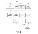
- Fig. 4 shows a configuration example of the confirmation apparatus 102.
- the confirmation apparatus 102 includes a CPU 131, a memory 132, a codec processing unit 133, and a graphic processing unit 134.
- the confirmation apparatus 102 includes a panel processing unit 135, a panel 136, a wired communication processing unit 137, a wired LAN terminal 138, a wireless communication processing unit, and an antenna 140.
- the CPU 131 controls operation of components of the confirmation apparatus 102.
- the memory 132 stores control software and data, and constitutes a work area of the CPU 131 and the like. In addition, the memory 132 temporarily records the image data of each frame transferred from the camera 101 (see Fig. 3).
- the memory 132 stores information on the frame numbers in relation to the image data of the frames written into the memory of each camera and sent from each camera. As described above, when the confirmation apparatus 102 reproduces the frame image of the predetermined frame number, the information is used to specify the camera that has the image data of the frame.
- the codec processing unit 133 reads the image data of each frame temporarily recorded in the frame buffer of the memory 132, and decompresses the image data for displaying the image.
- the panel processing unit 135 drives the panel 136 on the basis of the image data decompressed by the codec processing unit 133, and displays the image on the panel 136.
- the panel 136 includes an LCD, an organic EL panel, or the like.
- the panel 136 has a touch panel function. As necessary, UIs are also displayed on the panel 136 for user's operation.
- the wired communication processing unit 137 communicates via wire with an external device, i.e., the camera 101 in this embodiment, via a wired LAN terminal 138.
- the wireless communication processing unit 139 communicates wirelessly with the external device, i.e., the camera 101 in this embodiment, via an antenna 140. Note that either the wireless communication or the wired communication is selected.
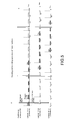
- FIG. 5 shows an example that each camera counts the frame numbers when the confirmation apparatus 102 sends the start trigger signal to each camera, and records the frames.
- the recorded frames of each camera correspond to the frames of the period, in which the moving object is present in the image capturing range of each camera.
- the confirmation apparatus 102 sends the start trigger signal (record instruction signal) to each camera, for example, on the basis of the user's operation.
- the start trigger signal record instruction signal
- each camera receives the start trigger signal, each camera is in a standby state for recording, and counts the frame numbers starting from the frame at the time t1.
- the frame number of the first frame is denoted as "1”
- the frame numbers of the subsequent frames are successively incremented. In this manner, the same frame number is assigned to the frames at the same time point taken by the respective cameras.
- Each camera does not record (write) the image data of all the frames in the frame buffer of the memory 112, but records only the image data of the frames of a period, in which a moving object is present in the image data. Thus, it is possible to reduce electric power consumption and to save the frame buffer of the memory 112.
- the camera (camera A) 101-A treats the frames having the frame numbers of "1" to "497” as recorded frames, records the image data of the respective frames in the frame buffer of the memory 112 in relation to the frame numbers, and sends information on the recorded-frame numbers including the recording-start frame number "1" and the recording-end frame number "497" to the confirmation apparatus 102.
- the camera (camera B) 101-B treats the frames having the frame numbers of "496" to "501" as recorded frames, records the image data of the respective frames in the frame buffer of the memory 112 in relation to the frame numbers, and sends information on the recorded-frame numbers including the recording-start frame number "1" and the recording-end frame number "501" to the confirmation apparatus 102.
- the camera (camera C) 101-C treats the frames having the frame numbers of "499" to "600” as recorded frames, records the image data of the respective frames in the frame buffer of the memory 112 in relation to the frame numbers, and sends information on the recorded-frame numbers including the recording-start frame number "499” and the recording-end frame number "600” to the confirmation apparatus 102.
- the confirmation apparatus 102 generates a table for switching an image taken by one camera to an image taken by another camera on the basis of the information on the recorded-frame numbers, and holds the table.
- the confirmation apparatus 102 sends the end trigger signal (record stop signal) to each camera, for example, on the basis of the user's operation.
- the end trigger signal record stop signal
- the standby state for recording of each camera may be preset after a predetermined time passes after sending the start trigger signal (record instruction signal).
- the confirmation apparatus 102 does not have to send the end trigger signal (record stop signal) to each camera.
- the respective cameras may not necessarily have the same exposure phase, for example, using a generator lock (Genlock).
- Genlock generator lock
- timing differences are permissible when the start trigger signal (record instruction signal) reaches the respective cameras from the confirmation apparatus 102.
- an image taken by one camera can be smoothly switched to an image taken by another camera when reproducing the image.
- Fig.7 shows an example of a screen for reproducing images (moving image content) captured by the multiple cameras and displayed on the panel 136 of the confirmation apparatus 102.
- the position of a frame to be reproduced corresponds to a recording period of the camera (camera A) 101-A, and an image 300 captured by the camera (camera A) 101-A is displayed.
- An UI screen is superimposed on the captured image of the screen for the user's operation.
- a user operates a play operation part 301, in which play icons are displayed.
- the image captured by the selected camera on the screen can be operated normally including reproduction, pause, fast forward, rewind, frame-by-frame advance, and the like.
- a scroll bar is provided next to the play icons, which is scrolled with a finger to perform frame-by-frame advance forward and backward, fast forward, and rewind.
- the user can perform a reproduction operation on a series of images from start to goal without regard to the plurality of cameras.
- the confirmation apparatus 102 automatically switches an image taken by one camera to an image taken by another other camera in response to the position of a frame to be reproduced (position of frame numbers to be reproduced).
- the confirmation apparatus 102 refers the above-described table for switching (see Fig. 6).
- the image taken by one camera is switched to the image taken by another camera in a period including overlapped positions of the frames of the two cameras, for example, near the middle of the overlapped positions of the frames. Note that information on timing of switching may be saved as a file, and may be used to automatically edit moving images of a main course.
- an image taken by one camera may be switched to an image taken by another camera at a predetermined timing when the two camera arranged side by side at intervals capture an image of the first sprinter at the same time.
- an image taken by one camera may be switched to an image taken by another camera after two frames after that timing, i.e., an offset may be preset.
- information on a radio frequency identification (RFID) tag may be used.
- RFID radio frequency identification
- an ID on a clothing may be detected by a camera and used.
- an image taken by one camera may be switched to an image taken by another camera at the moment of capturing an image of a predetermined person by using facial recognition, or the like. It should be appreciated that the present technology is applicable not only to a person's race but also to a car race, or the like.
- FIG. 8 is a diagram showing a communication sequence example between the confirmation apparatus 102 and each camera at the time of the reproduction.
- Fig. 8 shows a communication example that the images are displayed by frame-by-frame advance.
- the confirmation apparatus 102 requests the camera (camera A) 101-A to transfer the image data of the #495 frame (in this case, compressed and coded in JPEG format).
- the camera (camera A) 101-A reads the image data of the #495 frame in the frame buffer of the camera (camera A) 101-A, and transfers the image data to the confirmation apparatus 102.
- the image of the image data of the #495 frame is displayed on the panel 136 of the confirmation apparatus 102.
- the confirmation apparatus 102 similarly requests the camera (camera A) 101-A to transfer the image data of the #496 frame.
- the camera (camera A) 101-A reads the image data of the #496 frame in the frame buffer of the camera (camera A) 101-A, and transfers the image data to the confirmation apparatus 102.
- the image of the image data of the #496 frame is displayed on the panel 136 of the confirmation apparatus 102.
- the confirmation apparatus 102 switches the camera (camera A) 101-A to the (camera B) 101-B on the basis of the table for switching.
- the confirmation apparatus 102 requests the camera (camera B) 101-B to transfer the image data of the #497 frame.
- the camera (camera B) 101-B reads the image data of the #497 frame in the frame buffer of the camera (camera B) 101-B, and transfers the image data to the confirmation apparatus 102.
- the image of the image data of the #497 frame is displayed on the panel 136 of the confirmation apparatus 102. The similar operation will be repeated thereafter.
- the confirmation apparatus 102 acquires image data of a predetermined frame from a predetermined camera that took the image every time the confirmation apparatus 102 displays the image of the predetermined frame taken by the predetermined camera. In this case, it is undesirably expected to prolong display latency depending on the status of a communication path, in particular where the confirmation apparatus 102 is connected to each camera via the wireless LAN.
- the memory132 of the confirmation apparatus 102 includes the frame buffer, and a content-to-be-reproduced of each camera is downloaded to the frame buffer in advance. After the buffering, the confirmation apparatus 102 reproduces the images without communication, i.e., closed, and unaffected by the status of a communication path. As a result, the display latency is improved.
- each camera counts the frame numbers from the frame corresponding to the timing of receiving the start trigger signal from the confirmation apparatus 102, and writes, into the memory 112, the image data of the frames of the period, in which the moving object is present, in relation to the counted frame numbers.
- the confirmation apparatus 102 reproduces the frame image of the predetermined frame number
- the confirmation apparatus 102 selectively sends the transfer request including the frame number to the camera that has the image data of the frame, and the confirmation apparatus 102 displays the image of the image data sent from the predetermined camera.
- the user can confirm well the moving images of the moving objects captured sequentially by the respective cameras on the confirmation apparatus 102.
- the confirmation apparatus 102 records the frame numbers in relation to the moving images of all the cameras, the frame numbers being on the basis of the trigger signal.
- each camera intraframe-compresses the image data of the frames having the frame numbers. Therefore, the confirmation apparatus 102 communicates only with the camera having the image data of desired frames, and thus acquires the image data of the desired frames with low latency and a low transmission bandwidth.
- the confirmation apparatus 102 since the intraframe-compressed image data is reproduced, the confirmation apparatus 102 needs less process steps, and the image data can be reproduced with low (stress-free) display latency/frame rate.
- each camera sends information on the recorded-frame numbers including the recording-start frame number and the recording-end frame number to the confirmation apparatus 102.
- the confirmation apparatus 102 holds the table, the table being generated on the basis of the information on the recorded-frame numbers from the cameras (see Fig. 6).
- the confirmation apparatus 102 switches an image taken by one camera to an image taken by another camera with reference to the table.
- the table for switching is not limited to the one generated on the basis of the information on the recorded-frame numbers.
- Fig. 9A shows an example of the table for switching in which each camera does not intraframe-compress i.e., compress in the JPEG format as described in the above-described embodiment, moving image files, but encodes moving image files with a group of pictures (GOP) configuration such as the AVC, for example.
- the confirmation apparatus 102 uses GOP numbers and the frame numbers included in the GOP to specify the frames to be displayed.
- each camera encodes the frame, for example, having the GOP number of #1 and the frame number of #1 corresponding to the timing.
- Each camera records the image data of the GOPs including the image data of each frame for at least a period, in which a moving object is present in the frame buffer of the memory 112. Then, each camera sends to the confirmation apparatus 102 the information on the GOP number and the frame number of the recording-start frame "object IN GOP/frame#" and the GOP number and the frame number of the recording-end frame "object OUT GOP/frame#" for at least a period, in which a moving object is present in the image capturing range of the imager.
- Fig. 9B shows another example of the table for switching in which the respective cameras are time-code synchronized.
- the confirmation apparatus 102 uses a time code to specify the frame to be displayed.
- each camera records the image data of each frame for at least a period, in which a moving object is present in the frame buffer of the memory 112 with the time code. Then, each camera sends to the confirmation apparatus 102 the time code "object IN Timecode" of the frame number of the recording-start frame and the time code “object OUT time code” of the frame number of the recording-end frame for at least a period, in which a moving object is present in the image capturing range of the imager.
- the image data of the images captured by the cameras 101-A, 101-B, and 101-C has a frame rate of 60Hz.
- the present technology is also applicable to the case that the image data of the images captured by the cameras 101-A, 101-B, and 101-C has another frame rate, e.g., a high frame rate of 240Hz as shown in Fig. 5.
- the numbers of the cameras are three.
- the present technology is also applicable to the case that the number of the cameras is two, four, or more than four.
- each camera includes the control interface.
- the camera may not include the control interface, and an external control device may be provided for each camera.
- Fig. 10 shows a configuration example of the multi-camera system 10B of that case.
- the components of Fig. 10 corresponding to those of Fig. 1 are denoted by the same reference signs.
- Each of the cameras 101-A, 101-B, and 101-C includes no control interface (control I/F) unlike those of the multi-camera system 10A shown in Fig. 1.
- the cameras 101-A, 101-B, and 101-C include an external control device (control device A) 101-A, an external control device (control device B) 101-B, an external control device (control device C) 101-C having the similar functions as the control interface (control I/F), respectively.
- the confirmation apparatus 102 independent of the cameras 101-A, 101-B, and 101-C is provided.
- no confirmation apparatus 102 may be provided, and any of the cameras 101-A, 101-B, and 101-C may also function as the confirmation apparatus.
- Fig. 11 shows a configuration example of a multi-camera system 10C of that case.
- the components of Fig. 11 corresponding to those of Fig. 1 are denoted by the same reference signs.
- the multi-camera system 10C shown in Fig. 11 corresponds to the multi-camera system 10A shown in Fig. 1.
- Fig. 12 shows a configuration example of the multi-camera system 10D corresponding to the multi-camera system 10B shown in Fig. 10, detailed description of which is omitted. It should be understood by those skilled in the art that various modifications, combinations, sub-combinations and alterations may occur depending on design requirements and other factors insofar as they are within the scope of the appended claims or the equivalents thereof.
- the technology according to an embodiment of the present disclosure can be applied to various products.
- the technology according to an embodiment of the present disclosure may be applied to the medical environment, such as in a surgery room system.
- An information processing apparatus including a communication interface, and processing circuitry configured to transmit a start instruction to a first camera apparatus and a second camera apparatus, the start instruction causing the first camera apparatus to start incrementing a first counter and the second camera apparatus to start incrementing a second counter for a video recording time period; receive, from the first camera apparatus, a first recording-start frame identifier that indicates a value of the first counter when recording of a first video by the first camera apparatus starts within the video recording time period; receive, from the first camera apparatus, a second recording-end frame identifier that indicates the value of the second counter when recording of the first video by the first camera apparatus stops within the video recording time period; receive, from the second camera apparatus, a first recording-start frame identifier that identifies a value of the second counter when recording of a second video by the second camera apparatus starts within the video recording time period; and receive, from the second camera apparatus, a second recording-end frame identifier that identifies the value of the second counter
- the information processing apparatus according to any one of features (1)-(6), in which the processing circuitry is configured to request frames of the first video from the first camera apparatus based on the first recording-start frame identifier and the first recording-end frame identifier; receive the frames of the first video from the first camera apparatus; playback the frames of the first video received from the first camera apparatus; request frames of the second video from the second camera apparatus based on the second recording-start frame identifier and the second recording-end frame identifier; receive the frames of the first video from the first camera apparatus; and playback the frames of the second video received from the second camera apparatus.
- the first and second counters are frame counters.
- a system including a first camera apparatus; a second camera apparatus; and an information processing apparatus, including a communication interface, and processing circuitry configured to transmit a start instruction to the first camera apparatus and the second camera apparatus, the start instruction causing the first camera apparatus to start incrementing a first counter and the second camera apparatus to start incrementing a second counter for a video recording time period; receive, from the first camera apparatus, a first recording-start frame identifier that indicates a value of the first counter when recording of a first video by the first camera apparatus starts within the video recording time period; receive, from the first camera apparatus, a second recording-end frame identifier that indicates the value of the second counter when recording of the first video by the first camera apparatus stops within the video recording time period; receive, from the second camera apparatus, a first recording-start frame identifier that identifies a value of the second counter when recording of a second video by the second camera apparatus starts within the video recording time period; and receive, from the second camera apparatus, a second recording-end frame identifier that identifies the first camera
- a non-transitory computer-readable medium storing instructions which when executed by a computer cause the computer to perform a method for receiving recording-start frame and recording-end frame identifiers, the method including transmitting a start instruction to a first camera apparatus and a second camera apparatus, the start instruction causing the first camera apparatus to start incrementing a first counter and the second camera apparatus to start incrementing a second counter for a video recording time period; receiving, from the first camera apparatus, a first recording-start frame identifier that indicates a value of the first counter when recording of a first video by the first camera apparatus starts within the video recording time period; receiving, from the first camera apparatus, a second recording-end frame identifier that indicates the value of the second counter when recording of the first video by the first camera apparatus stops within the video recording time period; receiving, from the second camera apparatus, a first recording-start frame identifier that identifies a value of the second counter when recording of a second video by the second camera apparatus starts within the video recording time period; and receiving, from the second camera apparatus
- the non-transitory computer-readable medium according to any one features (10)-(15), further including requesting frames of the first video from the first camera apparatus based on the first recording-start frame identifier and the first recording-end frame identifier; receiving the frames of the first video from the first camera apparatus; playing back the frames of the first video received from the first camera apparatus; requesting frames of the second video from the second camera apparatus based on the second recording-start frame identifier and the second recording-end frame identifier; receiving the frames of the first video from the first camera apparatus; and playing back the frames of the second video received from the second camera apparatus.
- the non-transitory computer-readable medium according to any one of features (10)-(17), in which the first and second counters are frame counters.
- the method for receiving recording-start frame and recording-end frame identifiers according to any one of features (10)-(17).
- a multi-camera system including: a plurality of cameras; and a confirmation apparatus connected via wire or wirelessly to the plurality of cameras, each of the cameras including an imager, a memory, and a control unit that controls processing of, when receiving a start trigger signal from the confirmation apparatus, counting frame numbers from a frame corresponding to a timing of receiving the start trigger signal, processing of writing, into the memory, image data of frames of a period, in which a moving object is present in the image data, out of image data captured by the imager, in relation to the counted frame numbers, processing of sending information on the frame numbers in relation to the image data of the frames written into the memory, and processing of, when receiving a transfer request including a frame number from the confirmation apparatus, reading the image data of the frame specified by the frame number from the memory, and transferring the image data to the confirmation apparatus, the confirmation apparatus including a display, and a control unit that controls processing of sending the start trigger signal to each of the plurality of cameras, processing of sending the
- a camera including: an imager, a memory, and a control unit that controls processing of, when receiving a start trigger signal from the confirmation apparatus, counting frame numbers from a frame corresponding to a timing of receiving the start trigger signal, processing of writing, into the memory, image data of frames of a period, in which a moving object is present in the image data, out of image data captured by the imager, in relation to the counted frame numbers, processing of sending information on the frame numbers in relation to the image data of the frames written into the memory, and processing of, when receiving a transfer request including a frame number from the confirmation apparatus, reading the image data of the frame specified by the frame number from the memory, and transferring the image data to the confirmation apparatus, the confirmation apparatus including a display, and a control unit that controls processing of sending the start trigger signal to each of the plurality of cameras, processing of sending
- a processing method of a camera including an imager and a memory, the method including the steps of: when receiving a start trigger signal from the confirmation apparatus, counting frame numbers from a frame corresponding to a timing of receiving the start trigger signal; writing, into the memory, image data of frames of a period, in which a moving object is present in the image data, out of image data captured by the imager, in relation to the counted frame numbers; sending information on the frame numbers in relation to the image data of the frames written into the memory; and when receiving a transfer request including the frame number from the confirmation apparatus, reading the image data of the frame specified by the frame number from the memory and transferring to the confirmation apparatus.
- a confirmation apparatus including: a display, and a control unit that controls processing of sending the start trigger signal to each of the plurality of cameras, processing of sending the transfer request including the frame number to a predetermined camera selected from the plurality of cameras on the basis of the information on the frame numbers in relation to the image data of the frames written into the memory sent from each of the plurality of cameras, and processing of receiving the image data of the frame specified by the frame number transferred from the predetermined camera, and displaying an image of the image data on the display.
- the confirmation apparatus according to (7) further including: an operation part configured to operate a position of a frame to be reproduced.
- the confirmation apparatus according to (8), in which the operation part is a touch panel arranged on a screen of the display.
- a processing method of a confirmation apparatus including a display, the method including the steps of: sending the start trigger signal to each of the plurality of cameras; sending the transfer request including the frame number to a predetermined camera selected from the plurality of cameras on the basis of the information on the frame numbers in relation to the image data of the frames written into the memory sent from each of the plurality of cameras; and receiving the image data of the frame specified by the frame number transferred from the predetermined camera, and displaying an image of the image data on the display.
- a multi-camera system including: a plurality of cameras; and a confirmation apparatus connected via wire or wirelessly to the plurality of cameras, each of the cameras including an imager, a memory, and a control unit that controls processing of writing, into the memory, image data of frames of a period, in which a moving object is present in the image data, out of image data captured by the imager, processing of sending information on a frame period of the image data written into the memory, and processing of, when receiving a transfer request including information on a frame to be reproduced from the confirmation apparatus, reading the image data of the frame to be reproduced from the memory, and transferring the image data to the confirmation apparatus, the confirmation apparatus including a display, and a control unit that controls processing of sending the transfer request including the information on a frame to be reproduced to a predetermined camera selected from the plurality of cameras on the basis of the information on a frame period sent from each of the plurality of cameras, and processing of receiving the image data of the frame to be reproduced transferred from the predetermined camera, and displaying
- the confirmation apparatus in which the information on a frame period is information indicated by a frame number, a group of pictures (GOP) number and the frame number, or a time code.
- a camera including: an imager, a memory, and a control unit that controls processing of writing, into the memory, image data of frames of a period, in which a moving object is present in the image data, out of image data captured by the imager, processing of sending information on a frame period of the image data written into the memory, and processing of, when receiving a transfer request including information on a frame to be reproduced from the confirmation apparatus, reading the image data of the frame to be reproduced from the memory, and transferring the image data to the confirmation apparatus.
- a confirmation apparatus including: a display, and a control unit that controls processing of sending the transfer request including the information on a frame to be reproduced to a predetermined camera selected from the plurality of cameras on the basis of the information on a frame period sent from each of the plurality of cameras, and processing of receiving the image data of the frame to be reproduced transferred from the predetermined camera, and displaying an image of the image data on the display.
Landscapes
- Engineering & Computer Science (AREA)
- Multimedia (AREA)
- Signal Processing (AREA)
- Databases & Information Systems (AREA)
- Studio Devices (AREA)
- Television Signal Processing For Recording (AREA)
- Closed-Circuit Television Systems (AREA)
- Exposure Control For Cameras (AREA)
- Stereoscopic And Panoramic Photography (AREA)
Abstract
Cette invention concerne un appareil de traitement d'informations, comprenant un circuit configuré pour transmettre une instruction d'initiation à un premier appareil de caméra et à un second appareil de caméra. L'instruction d'initiation amène le premier appareil de caméra à initier l'incrémentation d'un premier compteur et le second appareil de caméra à initier l'incrémentation d'un second compteur pour une période de temps d'enregistrement vidéo. Le circuit reçoit, en provenance du premier appareil de caméra, un premier identifiant de trame de début d'enregistrement qui indique une valeur du premier compteur et un second identifiant de trame de fin d'enregistrement qui indique la valeur du second compteur. Le circuit reçoit, en provenance du second appareil de caméra, un premier identifiant de trame de début d'enregistrement qui identifie une valeur du second compteur et un second identifiant de trame de fin d'enregistrement qui identifie la valeur du second compteur.
Priority Applications (3)
| Application Number | Priority Date | Filing Date | Title |
|---|---|---|---|
| US16/066,733 US10708500B2 (en) | 2016-08-09 | 2017-08-02 | Multi-camera system, camera, processing method of camera, confirmation apparatus, and processing method of confirmation apparatus for capturing moving images |
| CN201780048109.4A CN109565562A (zh) | 2016-08-09 | 2017-08-02 | 多相机系统、相机、相机的处理方法、确认装置以及确认装置的处理方法 |
| EP17826589.8A EP3434008A2 (fr) | 2016-08-09 | 2017-08-02 | Système à caméras multiples, caméra, procédé de traitement de caméra, appareil de confirmation et procédé de traitement d'appareil de confirmation |
Applications Claiming Priority (2)
| Application Number | Priority Date | Filing Date | Title |
|---|---|---|---|
| JP2016156866A JP6801286B2 (ja) | 2016-08-09 | 2016-08-09 | マルチカメラシステム、カメラ、カメラの処理方法、確認装置および確認装置の処理方法 |
| JP2016-156866 | 2016-08-09 |
Publications (2)
| Publication Number | Publication Date |
|---|---|
| WO2018030242A2 true WO2018030242A2 (fr) | 2018-02-15 |
| WO2018030242A3 WO2018030242A3 (fr) | 2018-05-31 |
Family
ID=60953918
Family Applications (1)
| Application Number | Title | Priority Date | Filing Date |
|---|---|---|---|
| PCT/JP2017/028118 WO2018030242A2 (fr) | 2016-08-09 | 2017-08-02 | Système à caméras multiples, caméra, procédé de traitement de caméra, appareil de confirmation et procédé de traitement d'appareil de confirmation |
Country Status (5)
| Country | Link |
|---|---|
| US (1) | US10708500B2 (fr) |
| EP (1) | EP3434008A2 (fr) |
| JP (1) | JP6801286B2 (fr) |
| CN (1) | CN109565562A (fr) |
| WO (1) | WO2018030242A2 (fr) |
Families Citing this family (3)
| Publication number | Priority date | Publication date | Assignee | Title |
|---|---|---|---|---|
| JP6872704B2 (ja) * | 2017-09-14 | 2021-05-19 | パナソニックIpマネジメント株式会社 | 監視カメラシステム及び監視方法 |
| CN111371984B (zh) * | 2019-06-14 | 2021-09-17 | 杭州海康威视系统技术有限公司 | 确定抓拍机异常的方法、装置及存储介质 |
| JP2020205560A (ja) * | 2019-06-18 | 2020-12-24 | キヤノン株式会社 | 撮像装置およびその制御方法 |
Citations (1)
| Publication number | Priority date | Publication date | Assignee | Title |
|---|---|---|---|---|
| JP2006339703A (ja) | 2005-05-31 | 2006-12-14 | Furoobell:Kk | 画像処理装置および方法、プログラム、並びに記録媒体 |
Family Cites Families (14)
| Publication number | Priority date | Publication date | Assignee | Title |
|---|---|---|---|---|
| US6895126B2 (en) | 2000-10-06 | 2005-05-17 | Enrico Di Bernardo | System and method for creating, storing, and utilizing composite images of a geographic location |
| WO2002087218A2 (fr) * | 2001-04-20 | 2002-10-31 | Kewazinga Corp. | Ensemble de cameras maniables et indicateur associe |
| US20050091311A1 (en) * | 2003-07-29 | 2005-04-28 | Lund Christopher D. | Method and apparatus for distributing multimedia to remote clients |
| WO2006106496A1 (fr) * | 2005-04-03 | 2006-10-12 | Nice Systems Ltd. | Appareil et procedes pour le suivi semi-automatique et l’examen d’un objet ou un evenement dans un site controle |
| JP4416017B2 (ja) * | 2007-07-18 | 2010-02-17 | ソニー株式会社 | 撮像システム |
| US8711224B2 (en) * | 2007-08-06 | 2014-04-29 | Frostbyte Video, Inc. | Image capture system and method |
| CN101699862B (zh) * | 2009-11-16 | 2011-04-13 | 上海交通大学 | Ptz摄像机获取感兴趣区域高分辨率图像的方法 |
| CN101950426B (zh) * | 2010-09-29 | 2014-01-01 | 北京航空航天大学 | 一种多摄像机场景下车辆接力跟踪方法 |
| CN102568003B (zh) * | 2011-12-21 | 2015-04-08 | 北京航空航天大学深圳研究院 | 一种基于视频结构化描述的多摄像机目标跟踪方法 |
| WO2013100239A1 (fr) * | 2011-12-29 | 2013-07-04 | 주식회사 앤비젼 | Procédé de traitement d'images dans un système de vision stéréoscopique et appareil correspondant |
| US20130222583A1 (en) * | 2012-02-28 | 2013-08-29 | Research In Motion Limited | System and Method for Obtaining Images from External Cameras Using a Mobile Device |
| CN104660998B (zh) * | 2015-02-16 | 2018-08-07 | 阔地教育科技有限公司 | 一种接力跟踪方法及系统 |
| CN104751486B (zh) * | 2015-03-20 | 2017-07-11 | 安徽大学 | 一种多ptz相机的运动目标接力跟踪算法 |
| CA2967455A1 (fr) * | 2016-05-13 | 2017-11-13 | Tactacam LLC | Reseau de cameras sans fil |
-
2016
- 2016-08-09 JP JP2016156866A patent/JP6801286B2/ja active Active
-
2017
- 2017-08-02 WO PCT/JP2017/028118 patent/WO2018030242A2/fr active Application Filing
- 2017-08-02 EP EP17826589.8A patent/EP3434008A2/fr not_active Withdrawn
- 2017-08-02 CN CN201780048109.4A patent/CN109565562A/zh active Pending
- 2017-08-02 US US16/066,733 patent/US10708500B2/en active Active
Patent Citations (1)
| Publication number | Priority date | Publication date | Assignee | Title |
|---|---|---|---|---|
| JP2006339703A (ja) | 2005-05-31 | 2006-12-14 | Furoobell:Kk | 画像処理装置および方法、プログラム、並びに記録媒体 |
Also Published As
| Publication number | Publication date |
|---|---|
| US20190020820A1 (en) | 2019-01-17 |
| JP2018026685A (ja) | 2018-02-15 |
| US10708500B2 (en) | 2020-07-07 |
| EP3434008A2 (fr) | 2019-01-30 |
| JP6801286B2 (ja) | 2020-12-16 |
| WO2018030242A3 (fr) | 2018-05-31 |
| CN109565562A (zh) | 2019-04-02 |
Similar Documents
| Publication | Publication Date | Title |
|---|---|---|
| US10021302B2 (en) | Video recording method and device | |
| JP6747158B2 (ja) | マルチカメラシステム、カメラ、カメラの処理方法、確認装置および確認装置の処理方法 | |
| US10708500B2 (en) | Multi-camera system, camera, processing method of camera, confirmation apparatus, and processing method of confirmation apparatus for capturing moving images | |
| KR20150022532A (ko) | 컨텐츠 재생 방법 및 그에 따른 단말, 그에 따른 시스템 | |
| JP2008311888A (ja) | 画像記録装置、画像記録システム、画像再生方法 | |
| WO2020037672A1 (fr) | Procédé et système de synchronisation de données, plateforme mobile et support de stockage lisible | |
| US20180213185A1 (en) | Method and system for monitoring a scene based on a panoramic view | |
| JP6743604B2 (ja) | マルチカメラシステム、カメラ、カメラの処理方法、確認装置および確認装置の処理方法 | |
| JP7140177B2 (ja) | カメラ、カメラの制御方法、制御装置、制御装置の制御方法、システムおよびシステムの制御方法 | |
| US11017817B2 (en) | Image processing apparatus, image processing method, camera apparatus, remote control apparatus, and camera system | |
| JP2015161748A (ja) | 投影装置、画像処理装置およびそれらの制御方法 | |
| JP7031703B2 (ja) | 情報処理装置およびマルチカメラシステム | |
| US9258540B2 (en) | Imaging apparatus | |
| CN105100723B (zh) | 视频监控方法和装置 | |
| US20210409613A1 (en) | Information processing device, information processing method, program, and information processing system | |
| JP6436818B2 (ja) | 記録装置及び方法 | |
| JP2005117447A (ja) | 動画記録装置、動画記録方法および動画記録プログラム | |
| US20200035270A1 (en) | Image processing apparatus and image processing method | |
| JP2015142360A (ja) | 撮像装置及び雲台装置 | |
| JP5930807B2 (ja) | 撮像装置 | |
| JP2015186040A (ja) | 記録装置およびその制御方法 | |
| JP5509159B2 (ja) | 画像処理装置 | |
| JP2019110537A (ja) | 撮像装置および撮像方法 | |
| JP2017188831A (ja) | 画像記録装置及び画像記録装置の制御方法 | |
| JP2009038426A (ja) | 2重解像度ビデオカメラおよび2重解像度データ記録再生装置 |
Legal Events
| Date | Code | Title | Description |
|---|---|---|---|
| 121 | Ep: the epo has been informed by wipo that ep was designated in this application |
Ref document number: 17826589 Country of ref document: EP Kind code of ref document: A2 |
|
| WWE | Wipo information: entry into national phase |
Ref document number: 2017826589 Country of ref document: EP |
|
| ENP | Entry into the national phase |
Ref document number: 2017826589 Country of ref document: EP Effective date: 20181022 |
|
| NENP | Non-entry into the national phase |
Ref country code: DE |