WO2018029906A1 - 発光セラミックス及び波長変換装置 - Google Patents
発光セラミックス及び波長変換装置 Download PDFInfo
- Publication number
- WO2018029906A1 WO2018029906A1 PCT/JP2017/014945 JP2017014945W WO2018029906A1 WO 2018029906 A1 WO2018029906 A1 WO 2018029906A1 JP 2017014945 W JP2017014945 W JP 2017014945W WO 2018029906 A1 WO2018029906 A1 WO 2018029906A1
- Authority
- WO
- WIPO (PCT)
- Prior art keywords
- group
- mol
- luminescent
- site
- composition
- Prior art date
- Legal status (The legal status is an assumption and is not a legal conclusion. Google has not performed a legal analysis and makes no representation as to the accuracy of the status listed.)
- Ceased
Links
Images

Classifications
-
- C—CHEMISTRY; METALLURGY
- C09—DYES; PAINTS; POLISHES; NATURAL RESINS; ADHESIVES; COMPOSITIONS NOT OTHERWISE PROVIDED FOR; APPLICATIONS OF MATERIALS NOT OTHERWISE PROVIDED FOR
- C09K—MATERIALS FOR MISCELLANEOUS APPLICATIONS, NOT PROVIDED FOR ELSEWHERE
- C09K11/00—Luminescent materials, e.g. electroluminescent or chemiluminescent
- C09K11/08—Luminescent materials, e.g. electroluminescent or chemiluminescent containing inorganic luminescent materials
- C09K11/77—Luminescent materials, e.g. electroluminescent or chemiluminescent containing inorganic luminescent materials containing rare earth metals
- C09K11/7766—Luminescent materials, e.g. electroluminescent or chemiluminescent containing inorganic luminescent materials containing rare earth metals containing two or more rare earth metals
- C09K11/7767—Chalcogenides
- C09K11/7769—Oxides
-
- C—CHEMISTRY; METALLURGY
- C04—CEMENTS; CONCRETE; ARTIFICIAL STONE; CERAMICS; REFRACTORIES
- C04B—LIME, MAGNESIA; SLAG; CEMENTS; COMPOSITIONS THEREOF, e.g. MORTARS, CONCRETE OR LIKE BUILDING MATERIALS; ARTIFICIAL STONE; CERAMICS; REFRACTORIES; TREATMENT OF NATURAL STONE
- C04B35/00—Shaped ceramic products characterised by their composition; Ceramics compositions; Processing powders of inorganic compounds preparatory to the manufacturing of ceramic products
- C04B35/01—Shaped ceramic products characterised by their composition; Ceramics compositions; Processing powders of inorganic compounds preparatory to the manufacturing of ceramic products based on oxide ceramics
- C04B35/453—Shaped ceramic products characterised by their composition; Ceramics compositions; Processing powders of inorganic compounds preparatory to the manufacturing of ceramic products based on oxide ceramics based on zinc, tin, or bismuth oxides or solid solutions thereof with other oxides, e.g. zincates, stannates or bismuthates
- C04B35/457—Shaped ceramic products characterised by their composition; Ceramics compositions; Processing powders of inorganic compounds preparatory to the manufacturing of ceramic products based on oxide ceramics based on zinc, tin, or bismuth oxides or solid solutions thereof with other oxides, e.g. zincates, stannates or bismuthates based on tin oxides or stannates
-
- C—CHEMISTRY; METALLURGY
- C04—CEMENTS; CONCRETE; ARTIFICIAL STONE; CERAMICS; REFRACTORIES
- C04B—LIME, MAGNESIA; SLAG; CEMENTS; COMPOSITIONS THEREOF, e.g. MORTARS, CONCRETE OR LIKE BUILDING MATERIALS; ARTIFICIAL STONE; CERAMICS; REFRACTORIES; TREATMENT OF NATURAL STONE
- C04B35/00—Shaped ceramic products characterised by their composition; Ceramics compositions; Processing powders of inorganic compounds preparatory to the manufacturing of ceramic products
- C04B35/01—Shaped ceramic products characterised by their composition; Ceramics compositions; Processing powders of inorganic compounds preparatory to the manufacturing of ceramic products based on oxide ceramics
- C04B35/48—Shaped ceramic products characterised by their composition; Ceramics compositions; Processing powders of inorganic compounds preparatory to the manufacturing of ceramic products based on oxide ceramics based on zirconium or hafnium oxides, zirconates, zircon or hafnates
- C04B35/486—Fine ceramics
-
- C—CHEMISTRY; METALLURGY
- C09—DYES; PAINTS; POLISHES; NATURAL RESINS; ADHESIVES; COMPOSITIONS NOT OTHERWISE PROVIDED FOR; APPLICATIONS OF MATERIALS NOT OTHERWISE PROVIDED FOR
- C09K—MATERIALS FOR MISCELLANEOUS APPLICATIONS, NOT PROVIDED FOR ELSEWHERE
- C09K11/00—Luminescent materials, e.g. electroluminescent or chemiluminescent
- C09K11/08—Luminescent materials, e.g. electroluminescent or chemiluminescent containing inorganic luminescent materials
- C09K11/77—Luminescent materials, e.g. electroluminescent or chemiluminescent containing inorganic luminescent materials containing rare earth metals
- C09K11/7701—Chalogenides
-
- C—CHEMISTRY; METALLURGY
- C09—DYES; PAINTS; POLISHES; NATURAL RESINS; ADHESIVES; COMPOSITIONS NOT OTHERWISE PROVIDED FOR; APPLICATIONS OF MATERIALS NOT OTHERWISE PROVIDED FOR
- C09K—MATERIALS FOR MISCELLANEOUS APPLICATIONS, NOT PROVIDED FOR ELSEWHERE
- C09K11/00—Luminescent materials, e.g. electroluminescent or chemiluminescent
- C09K11/08—Luminescent materials, e.g. electroluminescent or chemiluminescent containing inorganic luminescent materials
- C09K11/77—Luminescent materials, e.g. electroluminescent or chemiluminescent containing inorganic luminescent materials containing rare earth metals
- C09K11/7701—Chalogenides
- C09K11/7703—Chalogenides with alkaline earth metals
-
- H—ELECTRICITY
- H10—SEMICONDUCTOR DEVICES; ELECTRIC SOLID-STATE DEVICES NOT OTHERWISE PROVIDED FOR
- H10H—INORGANIC LIGHT-EMITTING SEMICONDUCTOR DEVICES HAVING POTENTIAL BARRIERS
- H10H20/00—Individual inorganic light-emitting semiconductor devices having potential barriers, e.g. light-emitting diodes [LED]
- H10H20/80—Constructional details
- H10H20/85—Packages
- H10H20/8506—Containers
-
- H—ELECTRICITY
- H10—SEMICONDUCTOR DEVICES; ELECTRIC SOLID-STATE DEVICES NOT OTHERWISE PROVIDED FOR
- H10H—INORGANIC LIGHT-EMITTING SEMICONDUCTOR DEVICES HAVING POTENTIAL BARRIERS
- H10H20/00—Individual inorganic light-emitting semiconductor devices having potential barriers, e.g. light-emitting diodes [LED]
- H10H20/80—Constructional details
- H10H20/85—Packages
- H10H20/851—Wavelength conversion means
- H10H20/8511—Wavelength conversion means characterised by their material, e.g. binder
- H10H20/8512—Wavelength conversion materials
-
- H—ELECTRICITY
- H10—SEMICONDUCTOR DEVICES; ELECTRIC SOLID-STATE DEVICES NOT OTHERWISE PROVIDED FOR
- H10H—INORGANIC LIGHT-EMITTING SEMICONDUCTOR DEVICES HAVING POTENTIAL BARRIERS
- H10H20/00—Individual inorganic light-emitting semiconductor devices having potential barriers, e.g. light-emitting diodes [LED]
- H10H20/80—Constructional details
- H10H20/85—Packages
- H10H20/855—Optical field-shaping means, e.g. lenses
- H10H20/856—Reflecting means
-
- C—CHEMISTRY; METALLURGY
- C04—CEMENTS; CONCRETE; ARTIFICIAL STONE; CERAMICS; REFRACTORIES
- C04B—LIME, MAGNESIA; SLAG; CEMENTS; COMPOSITIONS THEREOF, e.g. MORTARS, CONCRETE OR LIKE BUILDING MATERIALS; ARTIFICIAL STONE; CERAMICS; REFRACTORIES; TREATMENT OF NATURAL STONE
- C04B2235/00—Aspects relating to ceramic starting mixtures or sintered ceramic products
- C04B2235/02—Composition of constituents of the starting material or of secondary phases of the final product
- C04B2235/30—Constituents and secondary phases not being of a fibrous nature
- C04B2235/32—Metal oxides, mixed metal oxides, or oxide-forming salts thereof, e.g. carbonates, nitrates, (oxy)hydroxides, chlorides
- C04B2235/3224—Rare earth oxide or oxide forming salts thereof, e.g. scandium oxide
-
- C—CHEMISTRY; METALLURGY
- C04—CEMENTS; CONCRETE; ARTIFICIAL STONE; CERAMICS; REFRACTORIES
- C04B—LIME, MAGNESIA; SLAG; CEMENTS; COMPOSITIONS THEREOF, e.g. MORTARS, CONCRETE OR LIKE BUILDING MATERIALS; ARTIFICIAL STONE; CERAMICS; REFRACTORIES; TREATMENT OF NATURAL STONE
- C04B2235/00—Aspects relating to ceramic starting mixtures or sintered ceramic products
- C04B2235/02—Composition of constituents of the starting material or of secondary phases of the final product
- C04B2235/30—Constituents and secondary phases not being of a fibrous nature
- C04B2235/32—Metal oxides, mixed metal oxides, or oxide-forming salts thereof, e.g. carbonates, nitrates, (oxy)hydroxides, chlorides
- C04B2235/3224—Rare earth oxide or oxide forming salts thereof, e.g. scandium oxide
- C04B2235/3225—Yttrium oxide or oxide-forming salts thereof
-
- C—CHEMISTRY; METALLURGY
- C04—CEMENTS; CONCRETE; ARTIFICIAL STONE; CERAMICS; REFRACTORIES
- C04B—LIME, MAGNESIA; SLAG; CEMENTS; COMPOSITIONS THEREOF, e.g. MORTARS, CONCRETE OR LIKE BUILDING MATERIALS; ARTIFICIAL STONE; CERAMICS; REFRACTORIES; TREATMENT OF NATURAL STONE
- C04B2235/00—Aspects relating to ceramic starting mixtures or sintered ceramic products
- C04B2235/02—Composition of constituents of the starting material or of secondary phases of the final product
- C04B2235/30—Constituents and secondary phases not being of a fibrous nature
- C04B2235/32—Metal oxides, mixed metal oxides, or oxide-forming salts thereof, e.g. carbonates, nitrates, (oxy)hydroxides, chlorides
- C04B2235/3224—Rare earth oxide or oxide forming salts thereof, e.g. scandium oxide
- C04B2235/3227—Lanthanum oxide or oxide-forming salts thereof
-
- C—CHEMISTRY; METALLURGY
- C04—CEMENTS; CONCRETE; ARTIFICIAL STONE; CERAMICS; REFRACTORIES
- C04B—LIME, MAGNESIA; SLAG; CEMENTS; COMPOSITIONS THEREOF, e.g. MORTARS, CONCRETE OR LIKE BUILDING MATERIALS; ARTIFICIAL STONE; CERAMICS; REFRACTORIES; TREATMENT OF NATURAL STONE
- C04B2235/00—Aspects relating to ceramic starting mixtures or sintered ceramic products
- C04B2235/02—Composition of constituents of the starting material or of secondary phases of the final product
- C04B2235/30—Constituents and secondary phases not being of a fibrous nature
- C04B2235/32—Metal oxides, mixed metal oxides, or oxide-forming salts thereof, e.g. carbonates, nitrates, (oxy)hydroxides, chlorides
- C04B2235/3231—Refractory metal oxides, their mixed metal oxides, or oxide-forming salts thereof
- C04B2235/3244—Zirconium oxides, zirconates, hafnium oxides, hafnates, or oxide-forming salts thereof
-
- C—CHEMISTRY; METALLURGY
- C04—CEMENTS; CONCRETE; ARTIFICIAL STONE; CERAMICS; REFRACTORIES
- C04B—LIME, MAGNESIA; SLAG; CEMENTS; COMPOSITIONS THEREOF, e.g. MORTARS, CONCRETE OR LIKE BUILDING MATERIALS; ARTIFICIAL STONE; CERAMICS; REFRACTORIES; TREATMENT OF NATURAL STONE
- C04B2235/00—Aspects relating to ceramic starting mixtures or sintered ceramic products
- C04B2235/02—Composition of constituents of the starting material or of secondary phases of the final product
- C04B2235/30—Constituents and secondary phases not being of a fibrous nature
- C04B2235/32—Metal oxides, mixed metal oxides, or oxide-forming salts thereof, e.g. carbonates, nitrates, (oxy)hydroxides, chlorides
- C04B2235/3298—Bismuth oxides, bismuthates or oxide forming salts thereof, e.g. zinc bismuthate
-
- C—CHEMISTRY; METALLURGY
- C04—CEMENTS; CONCRETE; ARTIFICIAL STONE; CERAMICS; REFRACTORIES
- C04B—LIME, MAGNESIA; SLAG; CEMENTS; COMPOSITIONS THEREOF, e.g. MORTARS, CONCRETE OR LIKE BUILDING MATERIALS; ARTIFICIAL STONE; CERAMICS; REFRACTORIES; TREATMENT OF NATURAL STONE
- C04B2235/00—Aspects relating to ceramic starting mixtures or sintered ceramic products
- C04B2235/65—Aspects relating to heat treatments of ceramic bodies such as green ceramics or pre-sintered ceramics, e.g. burning, sintering or melting processes
- C04B2235/656—Aspects relating to heat treatments of ceramic bodies such as green ceramics or pre-sintered ceramics, e.g. burning, sintering or melting processes characterised by specific heating conditions during heat treatment
- C04B2235/6567—Treatment time
-
- C—CHEMISTRY; METALLURGY
- C04—CEMENTS; CONCRETE; ARTIFICIAL STONE; CERAMICS; REFRACTORIES
- C04B—LIME, MAGNESIA; SLAG; CEMENTS; COMPOSITIONS THEREOF, e.g. MORTARS, CONCRETE OR LIKE BUILDING MATERIALS; ARTIFICIAL STONE; CERAMICS; REFRACTORIES; TREATMENT OF NATURAL STONE
- C04B2235/00—Aspects relating to ceramic starting mixtures or sintered ceramic products
- C04B2235/65—Aspects relating to heat treatments of ceramic bodies such as green ceramics or pre-sintered ceramics, e.g. burning, sintering or melting processes
- C04B2235/658—Atmosphere during thermal treatment
- C04B2235/6583—Oxygen containing atmosphere, e.g. with changing oxygen pressures
- C04B2235/6585—Oxygen containing atmosphere, e.g. with changing oxygen pressures at an oxygen percentage above that of air
-
- C—CHEMISTRY; METALLURGY
- C04—CEMENTS; CONCRETE; ARTIFICIAL STONE; CERAMICS; REFRACTORIES
- C04B—LIME, MAGNESIA; SLAG; CEMENTS; COMPOSITIONS THEREOF, e.g. MORTARS, CONCRETE OR LIKE BUILDING MATERIALS; ARTIFICIAL STONE; CERAMICS; REFRACTORIES; TREATMENT OF NATURAL STONE
- C04B2235/00—Aspects relating to ceramic starting mixtures or sintered ceramic products
- C04B2235/65—Aspects relating to heat treatments of ceramic bodies such as green ceramics or pre-sintered ceramics, e.g. burning, sintering or melting processes
- C04B2235/66—Specific sintering techniques, e.g. centrifugal sintering
- C04B2235/661—Multi-step sintering
- C04B2235/662—Annealing after sintering
- C04B2235/664—Reductive annealing
-
- C—CHEMISTRY; METALLURGY
- C04—CEMENTS; CONCRETE; ARTIFICIAL STONE; CERAMICS; REFRACTORIES
- C04B—LIME, MAGNESIA; SLAG; CEMENTS; COMPOSITIONS THEREOF, e.g. MORTARS, CONCRETE OR LIKE BUILDING MATERIALS; ARTIFICIAL STONE; CERAMICS; REFRACTORIES; TREATMENT OF NATURAL STONE
- C04B2235/00—Aspects relating to ceramic starting mixtures or sintered ceramic products
- C04B2235/70—Aspects relating to sintered or melt-casted ceramic products
- C04B2235/74—Physical characteristics
- C04B2235/76—Crystal structural characteristics, e.g. symmetry
-
- C—CHEMISTRY; METALLURGY
- C04—CEMENTS; CONCRETE; ARTIFICIAL STONE; CERAMICS; REFRACTORIES
- C04B—LIME, MAGNESIA; SLAG; CEMENTS; COMPOSITIONS THEREOF, e.g. MORTARS, CONCRETE OR LIKE BUILDING MATERIALS; ARTIFICIAL STONE; CERAMICS; REFRACTORIES; TREATMENT OF NATURAL STONE
- C04B2235/00—Aspects relating to ceramic starting mixtures or sintered ceramic products
- C04B2235/70—Aspects relating to sintered or melt-casted ceramic products
- C04B2235/96—Properties of ceramic products, e.g. mechanical properties such as strength, toughness, wear resistance
- C04B2235/9646—Optical properties
- C04B2235/9653—Translucent or transparent ceramics other than alumina
-
- H—ELECTRICITY
- H10—SEMICONDUCTOR DEVICES; ELECTRIC SOLID-STATE DEVICES NOT OTHERWISE PROVIDED FOR
- H10H—INORGANIC LIGHT-EMITTING SEMICONDUCTOR DEVICES HAVING POTENTIAL BARRIERS
- H10H20/00—Individual inorganic light-emitting semiconductor devices having potential barriers, e.g. light-emitting diodes [LED]
- H10H20/80—Constructional details
- H10H20/85—Packages
- H10H20/851—Wavelength conversion means
- H10H20/8515—Wavelength conversion means not being in contact with the bodies
Definitions
- the present invention relates to a luminescent ceramic and a wavelength conversion device using the luminescent ceramic.
- Patent Document 1 ABO W (where A is at least one selected from the group consisting of La, Y, Gd, Yb, and Lu, and B is selected from the group consisting of Zr, Sn, and Hf). And W is a positive number for maintaining electrical neutrality.) Obtained by heat-treating a ceramic mainly composed of a pyrochlore type compound represented by Luminescent ceramics are described.
- phosphors having an emission peak wavelength and / or emission spectrum shape suitable for the application and purpose are used. Therefore, it is required to supply phosphors having various emission peak wavelengths and / or emission spectrum shapes.
- the emission peak wavelength and emission spectrum shape are changed by changing the combination and composition ratio of the constituent elements of the luminescent ceramic.
- An object of the present invention is to provide a luminescent ceramic capable of realizing various emission peak wavelengths and a wavelength converter using the luminescent ceramic.
- the luminescent ceramic according to the first invention of the present application is ABO W (where A includes at least one selected from the group consisting of La, Y and Gd, and is selected from the group consisting of La, Y and Gd). At least one kind is contained in a total of 80 mol% or more, B contains at least one selected from the group consisting of Zr, Sn and Hf, and W is a positive number for maintaining electrical neutrality) 100 mol%, Bi In the luminescent ceramic made of a pyrochlore compound containing 0.01 mol% or more, the B contains at least Sn.
- the luminescent ceramic according to the first invention further contains at least one selected from the group consisting of Mg, Ca, Zn, Sr, Ba, Sc, Ga, In, Yb and Lu.
- the luminescent ceramic according to the second invention of the present application is ABO W (where A is at least one selected from the group consisting of La, Y and Gd, and is selected from the group consisting of La, Y and Gd). At least one kind is contained in a total of 80 mol% or more, B contains at least one selected from the group consisting of Zr, Sn and Hf, and W is a positive number for maintaining electrical neutrality) 100 mol%, Bi In the luminescent ceramic made of a pyrochlore compound containing 0.01 mol% or more, B contains at least Zr or Hf.
- the luminescent ceramic according to the second invention further contains at least one selected from the group consisting of Mg, Ca, Zn, Sr, Ba, Sc, Ga, In, Yb and Lu.
- the A contains at least 50 mol% of La.
- the first invention and the second invention are collectively referred to as the present invention.
- the content of at least one selected from the group consisting of Mg, Ca, Zn, Sr, Ba, Sc, Ga, In, Yb, and Lu is in total. It is 0.1 mol% or more.
- the content of at least one selected from the group consisting of Mg, Ca, Zn, Sr, Ba, Sc, Ga, In, Yb, and Lu is Bi. It is more than the content.
- the content of at least one selected from the group consisting of Mg, Ca, Zn, Sr, Ba, Sc, Ga, In, Yb, and Lu is 20 mol%. Is less than. In this case, the light transmittance can be effectively improved. More preferably, the content of at least one selected from the group consisting of Mg, Ca, Zn, Sr, Ba, Sc, Ga, In, Yb and Lu is 10 mol% or less.
- the A includes Mg, Ca, Zn, Sr, or Ba, or the B includes Sc, Ga, In, Yb, or Lu. One of them is included.
- the emission peak wavelength in the visible range when irradiated with ultraviolet rays is such that the Mg, Ca, Zn, Sr, Ba, Sc, Ga, In, Yb and Lu And at least one selected from the group consisting of Mg, Ca, Zn, Sr, Ba, Sc, Ga, In, Yb, and Lu. Except for the absence, the emission peak wavelength of the same luminescent ceramic is different by 10 nm or more.
- a wavelength conversion device includes a luminescent ceramic configured according to the present invention and a light source that irradiates the luminescent ceramic with ultraviolet rays.
- luminescent ceramic refers to absorption of at least part of the energy of the irradiated light when irradiated with light such as ultraviolet rays, and a wavelength different from the wavelength of the irradiated light. Ceramics that emit as light.
- the present invention it is possible to provide a luminescent ceramic and a wavelength converter capable of realizing even more various emission peak wavelengths.
- FIG. 1 is a schematic configuration diagram for explaining a wavelength conversion device as an embodiment of the present invention.
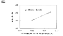
- FIG. 2 is a diagram showing the relationship between the average value of the ionic radii of the B site constituent ions and the lattice constant.
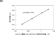
- FIG. 3 is a graph showing the relationship between the average value of the ionic radii of the A site constituting ions and the lattice constant.
- the luminescent ceramic according to the first invention of the present application is ABO W (where A includes at least one selected from the group consisting of La, Y and Gd, and is selected from the group consisting of La, Y and Gd). At least one kind is contained in a total of 80 mol% or more, B contains at least one selected from the group consisting of Zr, Sn and Hf, and W is a positive number for maintaining electrical neutrality) 100 mol%, Bi In the luminescent ceramic made of a pyrochlore type compound containing at least 0.01 mol%, B contains at least Sn.
- the luminescent ceramic according to the first invention further contains at least one selected from the group consisting of Mg, Ca, Zn, Sr, Ba, Sc, Ga, In, Yb and Lu.
- the luminescent ceramic according to the second invention of the present application is ABO W (where A includes at least one selected from the group consisting of La, Y and Gd, and is selected from the group consisting of La, Y and Gd). At least one kind is contained in a total of 80 mol% or more, B contains at least one selected from the group consisting of Zr, Sn and Hf, and W is a positive number for maintaining electrical neutrality) 100 mol%, Bi In the luminescent ceramic made of a pyrochlore compound in which 0.01 mol% or more is contained, B contains at least Zr or Hf.
- the luminescent ceramic according to the second invention further contains at least one selected from the group consisting of Mg, Ca, Zn, Sr, Ba, Sc, Ga, In, Yb and Lu.
- the A contains at least 50 mol% La.
- the luminescent ceramics according to the first and second inventions of the present application can be obtained by firing a ceramic material having the above composition ratio and then heat-treating in a reducing atmosphere. Since the luminescent ceramic of the present invention is a ceramic, it is easier to manufacture than a single crystal luminescent material. In the firing, the ceramic material may be fired in the form of a powder, or may be fired after being formed into a predetermined shape. In either case, the luminescent ceramic is obtained by heat treatment in a reducing atmosphere.
- the luminescent ceramics may be in the form of a powder or may be dispersed in a resin or glass.
- ABO W is a positive number for maintaining electrical neutrality.
- specific examples of ABO W include A 2 and B 2 O 7 .
- the luminescent ceramics ABOw of the present invention is made of a pyrochlore type compound. Since the pyrochlore structure is a superlattice structure of a defect fluorite structure, ABOw may take an intermediate structure between them, but in the present invention, it is a superlattice peak in X-ray diffraction (311) or ( As long as the peak of 331) is visible, the compound is a pyrochlore type compound.
- At least one element selected from the group consisting of Mg, Ca, Zn, Sr, Ba, Sc, Ga, In, Yb, and Lu is contained. It is added with. At least one of the above elements is co-added, and at the A site, at least one part selected from the group consisting of La, Y and Gd is selected, or at the B site, selected from the group consisting of Zr, Sn and Hf. In addition, at least one part is replaced by the at least one element.
- Bi at the B site, at least one part selected from the group consisting of Zr, Sn and Hf is replaced by Bi.
- 100 mol% of the A site contains at least 80 mol% in total of at least one element selected from the group consisting of La, Y and Gd. Thereby, luminescent ceramics having various emission peak wavelengths can be easily obtained.
- the B site contains Bi in a range of 0.001 mol% to 5 mol%.
- the quantum yield of light emission can be effectively increased. More preferably, it is the range of 0.01 mol% or more and 3 mol% or less, More preferably, it is 0.05 mol% or more and 1 mol% or less.
- the light transmittance is preferably 50% or more, more preferably 60% or more, and still more preferably 70% or more in the visible region, that is, in the wavelength range of 450 nm or more and 800 nm or less. It is preferable that
- Bi is contained in a proportion of 0.01 mol% or more with respect to 100 mol% of ABO W. Thereby, luminescent ceramics having various emission peak wavelengths can be easily obtained.
- the luminescent ceramic according to the present invention at least one element selected from the group consisting of Mg, Ca, Zn, Sr, Ba, Sc, Ga, In, Yb and Lu is added together with Bi.
- the added element may be substituted at the A site or may be substituted at the B site.
- the emission peak wavelength can be greatly shifted, and luminescent ceramics having various emission peak wavelengths can be provided.
- the content of at least one element selected from the group consisting of Mg, Ca, Zn, Sr, Ba, Sc, Ga, In, Yb, and Lu, that is, the co-addition amount, may be 0.1 mol% or more in total.
- luminescent ceramics having various emission peak wavelengths can be provided more easily.
- the content of at least one element selected from the group consisting of Mg, Ca, Zn, Sr, Ba, Sc, Ga, In, Yb, and Lu is greater than or equal to the Bi content.
- the above wavelength shift occurs more reliably, and it is possible to provide luminescent ceramics having more various emission peak wavelengths.
- the emission peak wavelength is larger than the original emission spectrum. It is difficult for the wavelength shift to occur.
- the wavelength shift of the emission peak wavelength is a group in which the emission peak wavelength in the visible region when irradiated with ultraviolet rays is composed of Mg, Ca, Zn, Sr, Ba, Sc, Ga, In, Yb, and Lu. It is assumed that a wavelength shift occurs when the emission peak wavelength of the same composition is different by 10 nm or more except that at least one element selected from the above is not added.
- light emission of various emission peak wavelengths is obtained by co-addition of at least one element selected from the group consisting of Mg, Ca, Zn, Sr, Ba, Sc, Ga, In, Yb, and Lu. It is possible to provide ceramics.
- the content of at least one element selected from the group consisting of Mg, Ca, Zn, Sr, Ba, Sc, Ga, In, Yb and Lu is preferably less than 20 mol% with respect to A100 mol% or B100 mol%. More preferably, it is 10 mol% or less. In this case, a luminescent ceramic excellent in light transmittance can be obtained.
- a site does not contain Bi.
- the luminescent ceramic is obtained by firing a ceramic having a composition of ABO W and then heat-treating it in a reducing atmosphere.
- the reason why the luminescent ceramic can be obtained by heat treatment in this reducing atmosphere is considered as follows.
- Bi is considered to be pentavalent in ceramics ABO W produced by firing.
- the ceramic ABO W is heat-treated in a reducing atmosphere, it is considered that Bi is changed from pentavalent to trivalent by supplying electrons to Bi from an oxygen site before reduction.
- the formation of this trivalent Bi is considered to cause the ceramic to emit light. That is, when the electrons in the 6s 2 orbit, which is the outermost electron orbit of trivalent Bi, transition to the higher energy 6s 6p orbit by irradiation with excitation light, and then deactivate to the original 6s 2 orbit. It is considered that light is emitted from
- the ceramic raw material powder is formed into a predetermined shape to form an unfired ceramic molded body.
- the unsintered ceramic molded body is fired in an atmosphere containing oxygen to produce ceramic ABO W.
- the firing atmosphere of the ceramic ABO W preferably has an oxygen concentration of 98% by volume or more.
- the firing temperature (maximum temperature) can be, for example, about 1500 ° C. or higher and 1800 ° C. or lower.
- the firing temperature (maximum temperature) holding time in the firing step can be, for example, about 5 hours or more and 100 hours or less.
- the obtained ceramic ABO W is heat-treated in a reducing atmosphere (reducing heat treatment) to produce a luminescent ceramic.
- the reducing atmosphere for heat treating the ceramic ABO W may be, for example, an H 2 / H 2 O atmosphere.
- the heat treatment temperature (maximum temperature) of the ceramic ABO W is preferably, for example, 800 ° C. or higher and 1200 ° C. or lower, and more preferably 900 ° C. or higher and 1100 ° C. or lower.
- the holding time at the heat treatment temperature (maximum temperature) of the ceramic ABO W can be, for example, about 1 hour or more and 100 hours or less.
- the light transmittance of the ceramic ABO W at wavelengths of 400 nm to 600 nm is improved by the heat treatment. This is because holes generated when the ceramic ABO W was produced by firing became a color center and absorbed light having a short wavelength of 400 nm or more and 600 nm or less. This is probably because electrons were supplied and the holes that had become color centers were neutralized.
- the luminescent ceramic according to the present invention is represented by ABO W , but the molar ratio of A to B (A: B) is not strictly limited to 1: 1.
- the luminescent ceramics ABO W includes those having a molar ratio (A / B) of A to B of 0.95 or more and 1.05 or less.
- the crystal system of the main component of the luminescent ceramic according to the present invention may be cubic.
- the luminescent ceramic is represented by ABO W , but contains impurities inevitably mixed in addition to the A, B, and O components (hereinafter referred to as “unavoidable impurities”). Also good. Specific examples of inevitable impurities include SiO 2 , B 2 O 3 , Al 2 O 3 and the like.
- FIG. 1 is a schematic configuration diagram showing a wavelength conversion device as one embodiment of the present invention.
- the wavelength conversion device 6 includes a wavelength conversion unit 1 and a light source 2.
- the wavelength converter 1 is made of the luminescent ceramic of the present invention.
- a light source 2 is provided on the substrate 4.
- the reflector 3 is disposed on the substrate 4 so as to surround the optical axis of the light emitted from the light source 2 while surrounding the light source 2.
- the wavelength conversion unit 1 is fixed to the light emission side end of the reflector 3 and faces the light source 2 at a position separated from the light source 2. For example, an LED or the like can be used as the light source 2.
- the excitation light When driving, the excitation light is irradiated from the light source 2 toward the wavelength conversion unit 1. A part of the excitation light is reflected by the reflector 3 and reaches the wavelength converter 1. The wavelength converter 1 is excited by excitation light and emits light.
- the wavelength conversion device 6 has been described, the wavelength conversion device of the present invention is not limited to the wavelength conversion device 6 shown in FIG. 1, and the wavelength conversion unit made of the luminescent ceramic of the present invention and the luminescent ceramic.
- Various types of wavelength converters having a light source that emits light can be provided.
- Example 1 As raw materials, La (OH) 3 , Gd 2 O 3 , Y 2 O 3 , ZrO 2 , HfO 2 , SnO 2 , MgCO 3 , CaCO 3 , ZnO 2 , SrCO 3 , BaCO 3 , Sc 2 O 3 , Ga 2 O 3 , In 2 O 3 , Yb 2 O 3 , Lu 2 O 3 , and Bi 2 O 3 were prepared. These raw materials were weighed so as to have a composition ratio represented by the molar ratio shown in Table 1 below, and wet-mixed for 20 hours using a ball mill. The obtained mixture was dried and calcined at 1300 ° C. for 3 hours to obtain a calcined product.
- Table 1 Table 1
- the calcined product was placed in a ball mill together with water and an organic dispersant, and wet pulverized for 12 hours.
- the obtained pulverized product was molded into a disk shape having a diameter of 30 mm and a thickness of 5 mm by a wet molding method.
- the obtained disk-shaped molded product was embedded in a powder having the same composition and fired at a temperature of 1700 ° C. for 20 hours in an oxygen atmosphere having an oxygen concentration of about 98% by volume to obtain a sintered body. Both surfaces of the obtained sintered body were mirror-polished so as to be a substrate having a thickness of 0.5 mm. Thereafter, the substrate was cut into a semicircle having a size of 1/2.
- the cut substrate was heat-treated in a reducing atmosphere of N 2 / H 2 / H 2 O mixed gas having an oxygen partial pressure of 1.7 ⁇ 10 ⁇ 13 MPa to obtain an evaluation sample.
- the maximum temperature during the heat treatment was 1000 ° C., and the holding time at 1000 ° C. was 3 hours.
- composition Nos Shown in Tables 1 and 2 below. Evaluation samples 1 to 11 were obtained.
- the evaluation sample obtained as described above was irradiated with ultraviolet light having a wavelength of 365 nm using FluoroMax-4P manufactured by Horiba Jobin Yvon, and the emission spectrum at that time was measured.
- the emission peak wavelengths of the obtained emission spectra are shown in Tables 1 and 2 below.
- the wavelength error in the table is about 5 nm. Since each evaluation sample had transparency, the linear transmittance in the visible light region was measured using an ultraviolet-visible spectrophotometer UV-2500PC manufactured by Shimadzu Corporation. 2 shows the linear transmittance.
- preparation composition ratio in Table 1 and Table 2 is a molar ratio.
- composition No. 2 it is a comparative example by adding at least one element selected from the group consisting of Mg, Ca, Zn, Sr, Ba, Sc, Ga, In, Yb and Lu to the A site.
- Composition No. 2 the content ratio of Mg is 1 mol%. It can be seen that there is a large shift from 700 nm of 1 to 575 nm.
- at least one selected from the group consisting of Mg, Ca, Zn, Sr, Ba, Sc, Ga, In, Yb, and Lu is present in any of the A site and the B site. It can be seen that the wavelength shift sufficiently occurs even when the element is contained. Furthermore, it can be seen that the linear transmittance is sufficiently high as 70% or more.
- Example 2 As in Example 1, except that the composition Nos. Shown in Tables 3, 4 and 5 below were used. 12 to 24 evaluation samples were obtained. About each obtained evaluation sample, the light emission peak wavelength and the linear transmittance
- the A site contains Ca as at least one element selected from the group consisting of Mg, Ca, Zn, Sr, Ba, Sc, Ga, In, Yb, and Lu
- Composition No. it is understood that no wavelength shift has occurred. That is, when the addition amount of Ca as at least one element selected from the group consisting of Mg, Ca, Zn, Sr, Ba, Sc, Ga, In, Yb, and Lu is 0.05 mol% or less with respect to the A site. No wavelength shift has occurred. In contrast, the addition amount of Ca as at least one element selected from the group consisting of Mg, Ca, Zn, Sr, Ba, Sc, Ga, In, Yb, and Lu is 0.1 mol with respect to the A site. In the case of% or more, a wavelength shift has occurred. Therefore, luminescent ceramics having various emission peak wavelengths can be provided.
- composition No. In No. 20 the Ca content was 20 mol% at the A site. In this case, although the wavelength shift occurred, the linear transmittance was as low as less than 50%. However, composition no. In Nos. 17 to 19, the Ca content is 10 mol% or less at the A site. In this case, the linear transmittance can be as high as 60% or more while causing a wavelength shift. Furthermore, composition No. In Nos. 13 to 16, the Ca content is 1 mol% or less at the A site. In this case, the linear transmittance can be as high as 70% or more while wavelength shift occurs.
- the addition amount of Ca as at least one element selected from the group consisting of Mg, Ca, Zn, Sr, Ba, Sc, Ga, In, Yb and Lu is 0.1 mol% at the A site. As mentioned above, it is desirable to set it as less than 20 mol%. More preferably, it can be seen that the amount of Ca added is desirably 10 mol% or less. More preferably, it can be seen that the amount of Ca added is desirably 1 mol% or less.
- Ca as at least one element selected from the group consisting of Mg, Ca, Zn, Sr, Ba, Sc, Ga, In, Yb and Lu is 0.05 mol at the A site.
- composition No. No. 21 has a wavelength shift because Ca is added more than Bi. Therefore, preferably, the content of the at least one element selected from the group consisting of Mg, Ca, Zn, Sr, Ba, Sc, Ga, In, Yb, and Lu is set to the B site of Bi. It can be seen that it is desirable to have more than the content.
- At least one selected from the group consisting of Mg, Ca, Zn, Sr, Ba, Sc, Ga, In, Yb, and Lu can be used to produce wavelength-shifted luminescent ceramics with various emission peak wavelengths.
- the content with respect to the A site containing the element is preferably 0.1 mol% or more, or more than the content of Bi with respect to the B site.
- the content relative to the A site containing at least one element selected from the group consisting of Mg, Ca, Zn, Sr, Ba, Sc, Ga, In, Yb and Lu. Is less than 20 mol%, more preferably 10 mol% or less.
- Example 3 In the same manner as in Example 1, the composition no. 25 to 34 evaluation samples were obtained. For each evaluation sample, the emission peak wavelength and linear transmittance were determined in the same manner as in Example 1. In Table 6, composition No. 1 and composition no. The result of 7 is also shown.
- Example 4 In the same manner as in Example 1, composition Nos. Shown in the following Tables 7 to 11 were used. Evaluation samples of 35 to 62 were obtained. In the same manner as in Example 1, the emission peak wavelength and linear transmittance were determined. The results are also shown in Tables 7 to 11.
- a wavelength shift occurs when the main element of the A site is La.
- no wavelength shift occurs when the main element at the A site is Gd or Y.
- composition No. 47 and composition No. Compared with 48 the emission peak wavelength is different by 5 nm. However, a difference of 5 nm in the emission peak wavelength is considered as a measurement error range.
- composition No. 3 in the evaluation sample of No. 3 composition No.
- composition No. 3 in the evaluation sample of No. 3 composition No.
- Lu in 11 evaluation samples the estimated value of the increase / decrease amount of the lattice constant when they were substituted at the A site or B site by 1 mol% was compared with the value actually obtained from the XRD spectrum. The results are shown in Table 12 below.
- composition No. Evaluation samples 1 to 62 were prepared.
- the ratio of each element in 1 to 62 is a molar ratio in the charged composition ratio.
- the molar ratio of the charged composition ratio is equivalent to the molar ratio as the content ratio of each element in the evaluation sample made of the sintered body actually obtained. This is confirmed by the content ratio of the obtained sintered body by XRF analysis.
- Table 13 below composition No. 3 and composition no. The result of having obtained the element content rate in the evaluation sample which is a sintered compact obtained from 11 by XRF analysis is shown.
- Example 5 The above composition No. 1 and the composition No. shown in Table 14 below. 63 evaluation samples were obtained in the same manner as in Example 1. In addition, composition No. 1 and composition no. For 63 evaluation samples, the emission peak wavelength was determined in the same manner as in Example 1. In addition, the lattice constant was measured. The results are also shown in Table 14 below.
- composition No. 1 As apparent from Table 14, the composition No. 1 and composition no. In any of the 63 evaluation samples, no shift of the emission peak wavelength occurred.
- Example 6 In the same manner as in Example 1, the composition no. Evaluation samples of 35, 36, and 64 to 71 were obtained. In the same manner as in Example 1, the emission peak wavelength and linear transmittance of the evaluation sample were determined. In addition, composition No. For the 35 evaluation samples, the lattice constant is also shown.
- composition No. 35 and composition no. From the comparison with Fig. 36, it can be seen that even when Sc is contained, the emission peak wavelength is shifted and sufficient linear transmittance can be obtained.
- composition No. From the results of 64-69, it can be seen that, as in the case of Ca, when Sc is co-added, a sufficient wavelength shift occurs when the content ratio of Sc is 0.1 mol% or more. On the other hand, when the content exceeds 20 mol%, the linear transmittance becomes composition No. It is confirmed that it is lower than the case of 69 evaluation samples.
- composition No. As can be seen from the evaluation samples 70 and 71, even when Sc is added together, the shift amount of the emission peak wavelength changes as the Bi content ratio changes.
- each element is present at the A site or the B site in the luminescent ceramic made of a pyrochlore type compound represented by ABO W finally obtained by preparation.
- Whether each element is present at the A site or the B site can be confirmed by, for example, XAFS (X-RAY ABSORPTION FINE STRUCTURE) using synchrotron radiation.
- XAFS X-RAY ABSORPTION FINE STRUCTURE
- This XAFS can obtain information on the presence site of an element and is often used for qualitative analysis.
- the occupancy rate of the element can be quantified by analysis.
- each element has absorption inherent to the element accompanying the inner shell transition. From this absorption spectrum, information such as the type, number, bond distance, and symmetry of atoms coordinated with the element of interest can be obtained. In the material, it is possible to know at which site each element exists from the information on the element known to exist at a predetermined site and the measurement result of XAFS.
Landscapes
- Chemical & Material Sciences (AREA)
- Engineering & Computer Science (AREA)
- Materials Engineering (AREA)
- Organic Chemistry (AREA)
- Ceramic Engineering (AREA)
- Inorganic Chemistry (AREA)
- Manufacturing & Machinery (AREA)
- Structural Engineering (AREA)
- Composite Materials (AREA)
- Luminescent Compositions (AREA)
Abstract
様々な発光ピーク波長を実現し得る発光セラミックスを提供する。 ABOW(ただし、Aは、La,Y及びGdからなる群から選択された少なくとも一種を含み、前記La,Y及びGdからなる群から選択された少なくとも一種を合計で80mol%以上含み、Bは、Zr,Sn及びHfからなる群から選択された少なくとも一種を含み、Wは電気的中性を保つための正の数)100mol%に対し、Biが0.01mol%以上含有されている、パイロクロア型化合物からなる発光セラミックスにおいて、前記Bは少なくともSnを含み、さらに、Mg,Ca,Zn,Sr,Ba,Sc,Ga,In,Yb及びLuからなる群から選択された少なくとも一種が含有されている、発光セラミックス。
Description
本発明は、発光セラミックス及び発光セラミックスを用いた波長変換装置に関する。
従来、光が照射されると、照射された光と異なる波長の光を出射する発光セラミックスが知られている。下記の特許文献1には、ABOW(但し、AはLa,Y,Gd,Yb及びLuからなる群から選択された少なくとも一種を含み、Bは、Zr,Sn及びHfからなる群から選択された少なくとも一種と、Biとを含み、Wは電気的中性を保つための正の数である。)で表されるパイロクロア型化合物を主成分とするセラミックスを還元雰囲気中において熱処理して得られた発光セラミックスが記載されている。
蛍光体を利用する種々の用途においては、用途や目的に適した発光ピーク波長及び/または発光スペクトル形状を有する蛍光体が用いられている。従って、様々な発光ピーク波長及び/または発光スペクトル形状を有する蛍光体を供給することが求められている。特許文献1では、発光セラミックスの構成元素の組み合わせや組成比を変化させることにより、発光ピーク波長や発光スペクトル形状が変化されている。しかしながら、特許文献1に記載のような構成だけでは、より一層広い範囲の様々な発光ピーク波長を有する波長変換素子を提供することができなかった。
本発明の目的は、様々な発光ピーク波長を実現し得る発光セラミックス、該発光セラミックスを用いた波長変換装置を提供することにある。
本願の第1の発明に係る発光セラミックスは、ABOW(ただし、Aは、La,Y及びGdからなる群から選択された少なくとも一種を含み、前記La,Y及びGdからなる群から選択された少なくとも一種を合計で80mol%以上含み、Bは、Zr,Sn及びHfからなる群から選択された少なくとも一種を含み、Wは電気的中性を保つための正の数)100mol%に対し、Biが0.01mol%以上含有されている、パイロクロア型化合物からなる発光セラミックスにおいて、前記Bは少なくともSnを含む。第1の発明に係る発光セラミックスには、さらに、Mg,Ca,Zn,Sr,Ba,Sc,Ga,In,Yb及びLuからなる群から選択された少なくとも一種が含有されている。
本願の第2の発明に係る発光セラミックスは、ABOW(ただし、Aは、La,Y及びGdからなる群から選択された少なくとも一種を含み、前記La,Y及びGdからなる群から選択された少なくとも一種を合計で80mol%以上含み、Bは、Zr,Sn及びHfからなる群から選択された少なくとも一種を含み、Wは電気的中性を保つための正の数)100mol%に対し、Biが0.01mol%以上含有されている、パイロクロア型化合物からなる発光セラミックスにおいて、前記Bは少なくともZrまたはHfを含む。第2の発明に係る発光セラミックスには、さらに、Mg,Ca,Zn,Sr,Ba,Sc,Ga,In,Yb及びLuからなる群から選択された少なくとも一種が含有されている。また、前記Aは少なくともLaを50mol%以上含む。
以下、第1の発明及び第2の発明を総称する際に本発明とする。
本発明に係る発光セラミックスの他の特定の局面では、前記Mg,Ca,Zn,Sr,Ba,Sc,Ga,In,Yb及びLuからなる群から選択された少なくとも一種の含有量が、合計で0.1mol%以上である。この場合には、Mg,Ca,Zn,Sr,Ba,Sc,Ga,In,Yb及びLuからなる群から選択された少なくとも一種の元素を含むことで発光ピーク波長をより一層大きくシフトさせることができる。
なお、本明細書において、元素の含有量mol%は、特に明記されていない限り、ABOW100mol%に対する割合である。
本発明に係る発光セラミックスの他の特定の局面では、前記Mg,Ca,Zn,Sr,Ba,Sc,Ga,In,Yb及びLuからなる群から選択された少なくとも一種の含有量は、Biの含有量以上である。この場合には、Mg,Ca,Zn,Sr,Ba,Sc,Ga,In,Yb及びLuからなる群から選択された少なくとも一種の元素を含むことで発光ピーク波長をより一層大きくシフトさせることができる。
本発明に係る発光セラミックスの他の特定の局面では、前記Mg,Ca,Zn,Sr,Ba,Sc,Ga,In,Yb及びLuからなる群から選択された少なくとも一種の含有量は、20mol%未満である。この場合には、光透過性を効果的に改善することができる。より好ましくは、Mg,Ca,Zn,Sr,Ba,Sc,Ga,In,Yb及びLuからなる群から選択された少なくとも一種の含有量は、10mol%以下である。
本発明に係る発光セラミックスの別の特定の局面では、前記AにMg,Ca,Zn,SrもしくはBaのいずれかが含まれており、または、前記BにSc,Ga,In,YbもしくはLuのいずれかが含まれている。
本発明に係る発光セラミックスのさらに他の特定の局面では、紫外線を照射されたときの可視域における発光ピーク波長が、前記Mg,Ca,Zn,Sr,Ba,Sc,Ga,In,Yb及びLuからなる群から選択された少なくとも一種が含有されていることにより、前記Mg,Ca,Zn,Sr,Ba,Sc,Ga,In,Yb及びLuからなる群から選択された少なくとも一種が含有されていないことを除いては同じ発光セラミックスの発光ピーク波長に比べて10nm以上異なっている。
本発明に係る波長変換装置は、本発明に従って構成されている発光セラミックスと、前記発光セラミックスに紫外線を照射する光源とを備える。
なお、本願で言う「発光セラミックス」とは、紫外線などの光を照射した際に、照射した光のエネルギーの少なくとも一部を吸収し、その吸収したエネルギーを照射した光の波長とは異なる波長の光として放射するセラミックスのことをいう。
本発明によれば、より一層様々な発光ピーク波長を実現し得る発光セラミックス及び波長変換装置を提供することができる。
以下、図面を参照しつつ、本発明の具体的な実施形態を説明することにより、本発明を明らかにする。
なお、本明細書に記載の各実施形態は、例示的なものであり、異なる実施形態間において、構成の部分的な置換または組み合わせが可能であることを指摘しておく。
以下、本発明の詳細を説明する。
(第1の発明に係る発光セラミックス)
本願の第1の発明に係る発光セラミックスは、ABOW(ただし、Aは、La,Y及びGdからなる群から選択された少なくとも一種を含み、上記La,Y及びGdからなる群から選択された少なくとも一種を合計で80mol%以上含み、Bは、Zr,Sn及びHfからなる群から選択された少なくとも一種を含み、Wは電気的中性を保つための正の数)100mol%に対し、Biが0.01mol%以上含有されている、パイロクロア型化合物からなる発光セラミックスにおいて、上記Bは少なくともSnを含む。第1の発明に係る発光セラミックスには、さらに、Mg,Ca,Zn,Sr,Ba,Sc,Ga,In,Yb及びLuからなる群から選択された少なくとも一種が含有されている。
本願の第1の発明に係る発光セラミックスは、ABOW(ただし、Aは、La,Y及びGdからなる群から選択された少なくとも一種を含み、上記La,Y及びGdからなる群から選択された少なくとも一種を合計で80mol%以上含み、Bは、Zr,Sn及びHfからなる群から選択された少なくとも一種を含み、Wは電気的中性を保つための正の数)100mol%に対し、Biが0.01mol%以上含有されている、パイロクロア型化合物からなる発光セラミックスにおいて、上記Bは少なくともSnを含む。第1の発明に係る発光セラミックスには、さらに、Mg,Ca,Zn,Sr,Ba,Sc,Ga,In,Yb及びLuからなる群から選択された少なくとも一種が含有されている。
(第2の発明に係る発光セラミックス)
本願の第2の発明に係る発光セラミックスは、ABOW(ただし、Aは、La,Y及びGdからなる群から選択された少なくとも一種を含み、上記La,Y及びGdからなる群から選択された少なくとも一種を合計で80mol%以上含み、Bは、Zr,Sn及びHfからなる群から選択された少なくとも一種を含み、Wは電気的中性を保つための正の数)100mol%に対し、Biが0.01mol%以上含有されている、パイロクロア型化合物からなる発光セラミックスにおいて、上記Bは少なくともZrまたはHfを含む。第2の発明に係る発光セラミックスには、さらに、Mg,Ca,Zn,Sr,Ba,Sc,Ga,In,Yb及びLuからなる群から選択された少なくとも一種が含有されている。また、上記Aは少なくともLaを50mol%以上含む。
本願の第2の発明に係る発光セラミックスは、ABOW(ただし、Aは、La,Y及びGdからなる群から選択された少なくとも一種を含み、上記La,Y及びGdからなる群から選択された少なくとも一種を合計で80mol%以上含み、Bは、Zr,Sn及びHfからなる群から選択された少なくとも一種を含み、Wは電気的中性を保つための正の数)100mol%に対し、Biが0.01mol%以上含有されている、パイロクロア型化合物からなる発光セラミックスにおいて、上記Bは少なくともZrまたはHfを含む。第2の発明に係る発光セラミックスには、さらに、Mg,Ca,Zn,Sr,Ba,Sc,Ga,In,Yb及びLuからなる群から選択された少なくとも一種が含有されている。また、上記Aは少なくともLaを50mol%以上含む。
(本発明の発光セラミックスの詳細)
本願の第1,第2の発明に係る発光セラミックスは、上記組成比を有するセラミック材料を焼成し、しかる後、還元雰囲気中において熱処理することにより得られる。本発明の発光セラミックスは、セラミックスであるため、単結晶の発光材料に比べて、製造が容易である。上記焼成において、上記セラミック材料は、粉末状のまま焼成されてもよいし、一旦所定形状に成形した後に焼成されてもよい。いずれにおいても還元雰囲気中において熱処理されることで発光セラミックスが得られる。発光セラミックスは粉末状でもよく、樹脂やガラスなどに分散させてもよい。粉末状や樹脂もしくはガラスに分散させた状態のいずれの場合でも、波長変換機能を有する素子を作製するための素材として利用することができる。上記ABOWにおいて、Wは、電気的中性を保つための正の数である。例えば、Wが3.5の場合、ABOWの具体例としては、A2及びB2O7が挙げられる。
本願の第1,第2の発明に係る発光セラミックスは、上記組成比を有するセラミック材料を焼成し、しかる後、還元雰囲気中において熱処理することにより得られる。本発明の発光セラミックスは、セラミックスであるため、単結晶の発光材料に比べて、製造が容易である。上記焼成において、上記セラミック材料は、粉末状のまま焼成されてもよいし、一旦所定形状に成形した後に焼成されてもよい。いずれにおいても還元雰囲気中において熱処理されることで発光セラミックスが得られる。発光セラミックスは粉末状でもよく、樹脂やガラスなどに分散させてもよい。粉末状や樹脂もしくはガラスに分散させた状態のいずれの場合でも、波長変換機能を有する素子を作製するための素材として利用することができる。上記ABOWにおいて、Wは、電気的中性を保つための正の数である。例えば、Wが3.5の場合、ABOWの具体例としては、A2及びB2O7が挙げられる。
本発明の発光セラミックスABOwは、パイロクロア型化合物からなる。パイロクロア構造は、欠陥蛍石型構造の超格子構造であるため、ABOwは両者の中間的な構造をとることがあるが、本発明では、X線回折において超格子ピークである(311)あるいは(331)のピークが見える限り、パイロクロア型化合物とする。
本発明においては、Mg,Ca,Zn,Sr,Ba,Sc,Ga,In,Yb及びLuからなる群から選択された少なくとも一種の元素が含有されているが、この少なくとも一種の元素は、Biと共に添加されている。少なくとも一種の上記元素が共添加され、Aサイトにおいて、La,Y及びGdからなる群から選択された少なくとも一種の一部が、あるいは、Bサイトにおいて、Zr,Sn及びHfからなる群から選択された少なくとも一種の一部が、上記少なくとも一種の元素により置換されていることになる。
Biについても、Bサイトにおいて、Zr,Sn及びHfからなる群から選択された少なくとも一種の一部がBiにより置換されていることになる。
本発明においては、Aサイト100mol%において、La,Y及びGdからなる群から選択された少なくとも一種の元素を合計で、80mol%以上含まれている。このことにより、様々な発光ピーク波長の発光セラミックスを容易に得ることができる。
好ましくは、特許文献1に記載のように、Bサイトが、Biを0.001mol%以上、5mol%以下の範囲で含むことが好ましい。それによって、発光の量子収率を効果的に高めることができる。より好ましくは、0.01mol%以上、3mol%以下の範囲であり、さらに好ましくは、0.05mol%以上、1mol%以下である。また、本発明に係る発光セラミックスは、可視域、すなわち波長450nm以上、800nm以下の範囲において、光透過率が50%以上であることが好ましく、より好ましくは60%以上、さらに好ましくは70%以上であることが好ましい。
Biは、ABOW100mol%に対し、0.01mol%以上の割合で含有されている。それによって、発光ピーク波長が様々な発光セラミックスを容易に得ることができる。
本発明に係る発光セラミックスでは、Mg,Ca,Zn,Sr,Ba,Sc,Ga,In,Yb及びLuからなる群から選択された少なくとも一種の元素は、Biと共に添加されているが、この共添加された元素は、Aサイトに置換されていてもよく、Bサイトに置換されていてもよい。いずれの場合においても、共添加により、発光ピーク波長を大きくシフトさせ、様々な発光ピーク波長の発光セラミックスを提供することができる。
Mg,Ca,Zn,Sr,Ba,Sc,Ga,In,Yb及びLuからなる群から選択された少なくとも一種の元素の含有量すなわち共添加量は、合計で0.1mol%以上であることが好ましく、それによって、発光ピーク波長が様々な発光セラミックスをより一層容易に提供することができる。
好ましくは、上記Mg,Ca,Zn,Sr,Ba,Sc,Ga,In,Yb及びLuからなる群から選択された少なくとも一種の元素の含有量は、Biの含有量以上である。その場合には、上記波長シフトがより一層確実に起こり、より一層様々な発光ピーク波長の発光セラミックスを提供することができる。
上記Mg,Ca,Zn,Sr,Ba,Sc,Ga,In,Yb及びLuからなる群から選択された少なくとも一種の元素の添加量が少なすぎると、元の発光スペクトルに比べて、発光ピーク波長の波長シフトが生じ難い。ここで、発光ピーク波長の波長シフトとは、紫外線を照射された時の可視域における発光ピーク波長が、上記Mg,Ca,Zn,Sr,Ba,Sc,Ga,In,Yb及びLuからなる群から選択された少なくとも一種の元素が添加されていないことを除いては同じ組成の発光セラミックスの発光ピーク波長に比べて、10nm以上異なっている場合に、波長シフトが生じているとする。
従って、本発明においては、上記Mg,Ca,Zn,Sr,Ba,Sc,Ga,In,Yb及びLuからなる群から選択された少なくとも一種の元素の共添加により、様々な発光ピーク波長の発光セラミックスを提供することが可能とされている。
上記Mg,Ca,Zn,Sr,Ba,Sc,Ga,In,Yb及びLuからなる群から選択された少なくとも一種の元素の含有量は、好ましくは、A100mol%またはB100mol%に対し、20mol%未満であり、より好ましくは、10mol%以下である。この場合には、光透過率に優れた発光セラミックスを得ることができる。
また、AサイトはBiを含まないことが好ましい。
(発光セラミックスの製造方法)
上記発光セラミックスは、ABOWの組成のセラミックスを焼成により得たのちに、還元雰囲気中において熱処理することにより得られる。この還元雰囲気中において熱処理することにより発光セラミックスが得られる理由は、以下の通りと考えられる。
上記発光セラミックスは、ABOWの組成のセラミックスを焼成により得たのちに、還元雰囲気中において熱処理することにより得られる。この還元雰囲気中において熱処理することにより発光セラミックスが得られる理由は、以下の通りと考えられる。
すなわち、特許文献1に示される通り、焼成により作製されたセラミックスABOWにおいて、Biは5価で存在すると考えられる。セラミックスABOWを還元雰囲気中において熱処理すると、還元前の酸素サイトからBiに電子が供給されることにより、上記Biが5価から3価に変化するものと考えられる。この3価のBiが形成されることによりセラミックスが発光するようになるものと考えられる。つまり、3価のBiの最外殻電子軌道である6s2軌道にある電子が、励起光の照射により、よりエネルギーの高い6s6p軌道へ遷移し、その後、元の6s2軌道に失活する際に光が出射されるものと考えられる。
本発明の発光セラミックスの具体的な製造方法を以下において説明する。
まず、セラミック原料粉末を所定の形状に形成し、未焼成のセラミック成形体を形成する。次に、その未焼成のセラミック成形体を酸素を含む雰囲気中において焼成することにより、セラミックスABOWを作製する。セラミックスABOWの焼成雰囲気は、酸素濃度が98体積%以上であることが好ましい。焼成温度(最高温度)は、例えば、1500℃以上、1800℃以下程度とすることができる。焼成工程における焼成温度(最高温度)保持時間は、例えば、5時間以上、100時間以下程度とすることができる。
次に、得られたセラミックスABOWを還元雰囲気中において熱処理(還元熱処理)することにより発光セラミックスを作製する。セラミックスABOWを熱処理する還元雰囲気は、例えば、H2/H2O雰囲気であってもよい。セラミックスABOWの熱処理温度(最高温度)は、例えば、800℃以上、1200℃以下であることが好ましく、900℃以上、1100℃以下であることがより好ましい。また、セラミックスABOWの熱処理温度(最高温度)における保持時間は、例えば、1時間以上、100時間以下程度とすることができる。
なお、セラミックスABOWの波長400nm以上、600nm以下における光透過率は、上記熱処理により向上する。これは、セラミックスABOWを焼成により作製する際に生じたホールがカラーセンターとなって波長400nm以上、600nm以下といった短波長の光を吸収していたところ、上記還元アニールによって還元前の酸素サイトから電子が供給され、カラーセンターとなっていたホールが中和されたためであると考えられる。
なお、上述の通り、本発明に係る発光セラミックスは、ABOWで表されるが、AとBのモル比(A:B)は、厳密に1:1に限定されるものではない。本発明において、発光セラミックスABOWには、AとBのモル比(A/B)が0.95以上、1.05以下であるものも含まれるものとする。
本発明に係る発光セラミックスの主成分の結晶系は、立方晶であってもよい。
また、発光セラミックスは、ABOWで表されるものであるが、A,B,O成分以外に、不可避的に混入する不純物(以下、「不可避的不純物」とする。)を含むものであってもよい。不可避的不純物の具体例としては、SiO2,B2O3,Al2O3等が挙げられる。
(波長変換装置の実施形態)
図1は、本発明の一実施形態としての波長変換装置を示す概略構成図である。
図1は、本発明の一実施形態としての波長変換装置を示す概略構成図である。
波長変換装置6は、波長変換部1と光源2とを含む。波長変換部1は、本発明の発光セラミックスからなる。基板4上に光源2が設けられている。光源2の周囲を囲みつつ、光源2から出射される光の光軸を囲むように、リフレクタ3が基板4上に配置されている。波長変換部1は、リフレクタ3の光出射側端部に固定されており、光源2と離隔された位置で光源2に対して対向されている。光源2としては、例えば、LEDなどを用いることができる。
駆動に際しては、光源2から励起光を波長変換部1に向かって照射する。励起光の一部がリフレクタ3によって反射され、波長変換部1に到達する。波長変換部1は、励起光により励起され、発光する。
なお、波長変換装置6について説明したが、本発明の波長変換装置は、図1に示した波長変換装置6に限定されるものではなく、本発明の発光セラミックスからなる波長変換部とこの発光セラミックスに光を出射する光源とを有する様々な形態の波長変換装置を提供することができる。
(実施例及び比較例)
次に本発明の発光セラミックスの実施例及び比較例を述べることにより、本発明をより詳細に説明する。なお、本発明は以下の実施例に限定されるものではない。
次に本発明の発光セラミックスの実施例及び比較例を述べることにより、本発明をより詳細に説明する。なお、本発明は以下の実施例に限定されるものではない。
(実施例1)
原料として、La(OH)3、Gd2O3、Y2O3、ZrO2、HfO2、SnO2、MgCO3、CaCO3、ZnO2、SrCO3、BaCO3、Sc2O3、Ga2O3、In2O3、Yb2O3、Lu2O3、及びBi2O3を用意した。これらの原料を下記の表1のモル比で示す組成比となるように秤量し、ボールミルを用いて20時間湿式混合した。得られた混合物を乾燥した後、1300℃で3時間仮焼し、仮焼物を得た。
原料として、La(OH)3、Gd2O3、Y2O3、ZrO2、HfO2、SnO2、MgCO3、CaCO3、ZnO2、SrCO3、BaCO3、Sc2O3、Ga2O3、In2O3、Yb2O3、Lu2O3、及びBi2O3を用意した。これらの原料を下記の表1のモル比で示す組成比となるように秤量し、ボールミルを用いて20時間湿式混合した。得られた混合物を乾燥した後、1300℃で3時間仮焼し、仮焼物を得た。
上記仮焼物を、水及び有機分散剤とともにボールミルに入れ、12時間湿式粉砕した。得られた粉砕物を湿式成形法により、直径30mm×厚さ5mmの円盤状に成形した。得られた円盤状の成型物を、同じ組成の粉体に埋め、約98体積%の酸素濃度の酸素雰囲気下において、1700℃の温度で20時間焼成し、焼結体を得た。得られた焼結体の両面を、厚みが0.5mmの基板となるように鏡面研磨した。しかる後、上記基板を1/2の大きさの半円状に切断した。切断された基板を、酸素分圧が1.7×10-13MPaのN2/H2/H2O混合ガスの還元雰囲気中において、熱処理し、評価サンプルを得た。熱処理に際しての最高温度は1000℃とし、1000℃における保持時間は3時間とした。
上記のようにして、下記の表1及び表2に示す組成No.1~11の評価サンプルを得た。
上記のようにして得られた評価サンプルについて、Horiba Jobin Yvon社製、FluoroMax-4Pを用い、波長365nmの紫外線を照射し、その際の発光スペクトルを測定した。得られた発光スペクトルの発光ピーク波長を下記の表1及び表2に示す。なお、表中の波長の誤差は5nm程度である。また、各評価サンプルは透明性を有していたので、島津製作所製、紫外可視分光光度計UV-2500PCを用い、可視光域での直線透過率を測定し、700nmにおける値を表1及び表2に直線透過率として示した。
なお、表1及び表2における仕込み組成比は、モル比である。

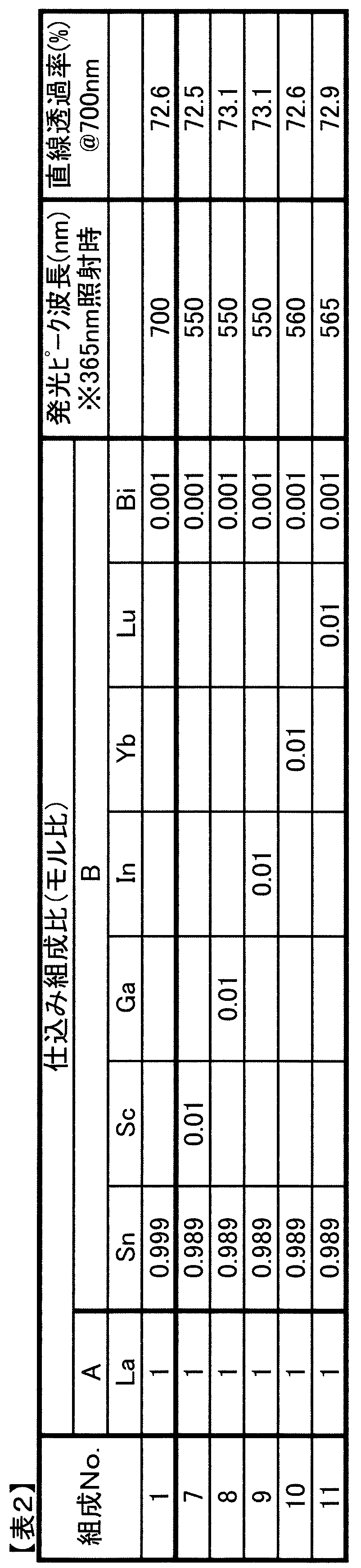
表1及び表2から、Aサイトに、Mg,Ca,Zn,Sr,Ba,Sc,Ga,In,Yb及びLuからなる群から選択された少なくとも一種の元素を加えることにより、比較例である組成No.1に比べ、発光ピーク波長を大きく変化させ得ることがわかる。例えば、組成No.2では、Mgの含有割合が1mol%であるため、発光ピーク波長は組成No.1の700nmから、575nmまで大きくシフトしていることがわかる。また、表1及び表2から明らかなように、Aサイト及びBサイトのいずれにMg,Ca,Zn,Sr,Ba,Sc,Ga,In,Yb及びLuからなる群から選択された少なくとも一種の元素を含有させた場合においても、上記波長シフトが十分に生じていることがわかる。さらに、直線透過率においても、70%以上と十分に高いことがわかる。
(実施例2)
実施例1と同様にして、但し下記の表3、表4及び表5に示す組成No.12~24の評価サンプルを得た。得られた各評価サンプルについて、実施例1と同様に、発光ピーク波長と直線透過率とを求めた。結果を、表3、表4及び表5に示す。なお、表3、表4及び表5における仕込み組成比は、モル比である。
実施例1と同様にして、但し下記の表3、表4及び表5に示す組成No.12~24の評価サンプルを得た。得られた各評価サンプルについて、実施例1と同様に、発光ピーク波長と直線透過率とを求めた。結果を、表3、表4及び表5に示す。なお、表3、表4及び表5における仕込み組成比は、モル比である。
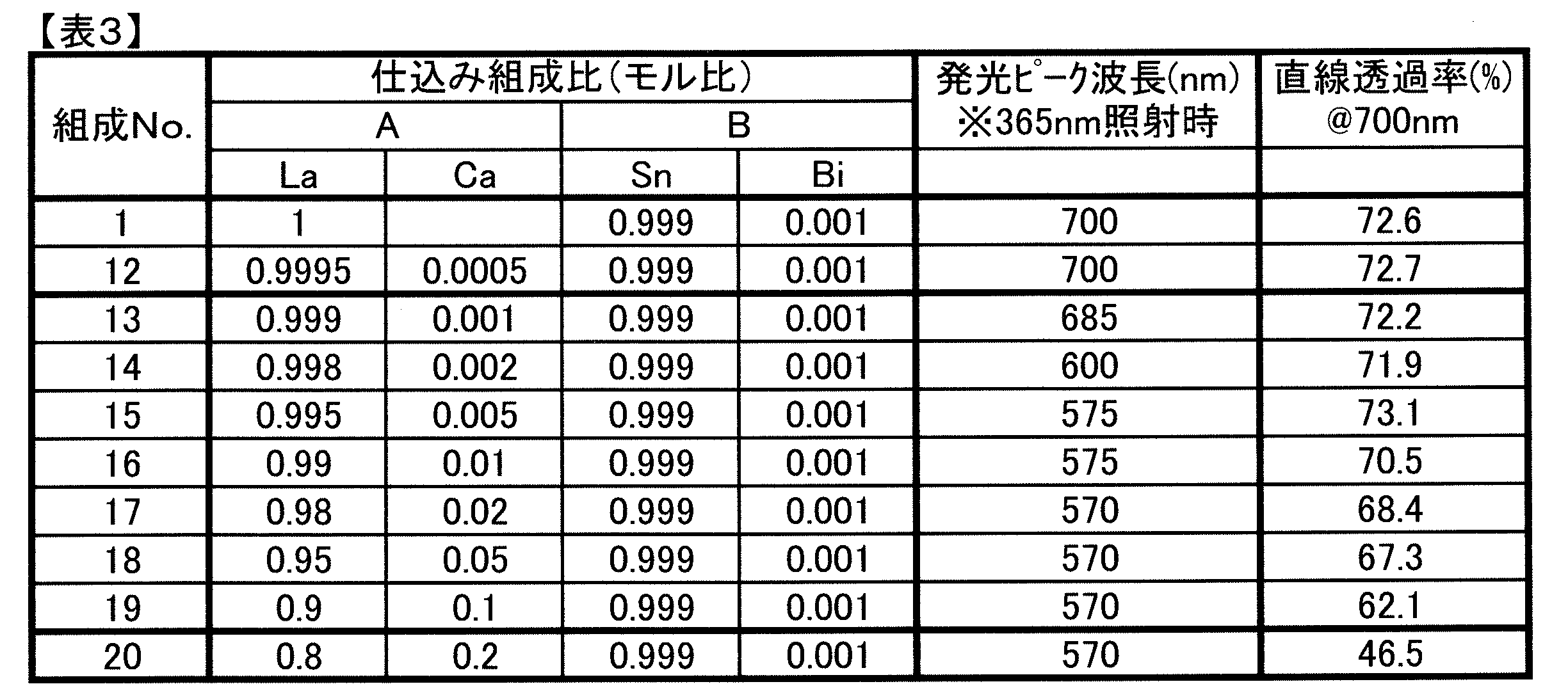
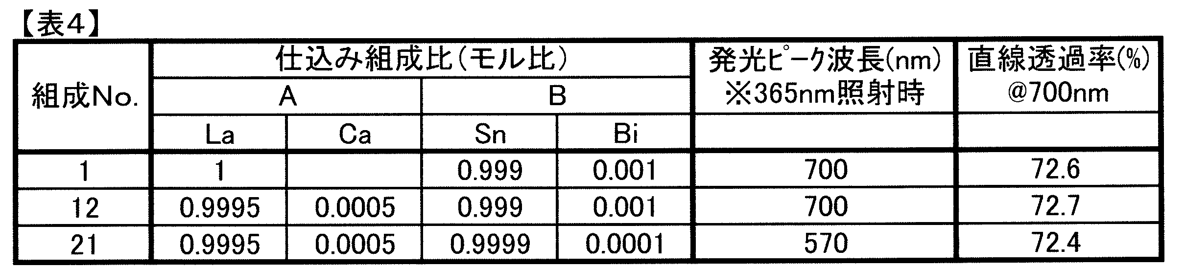
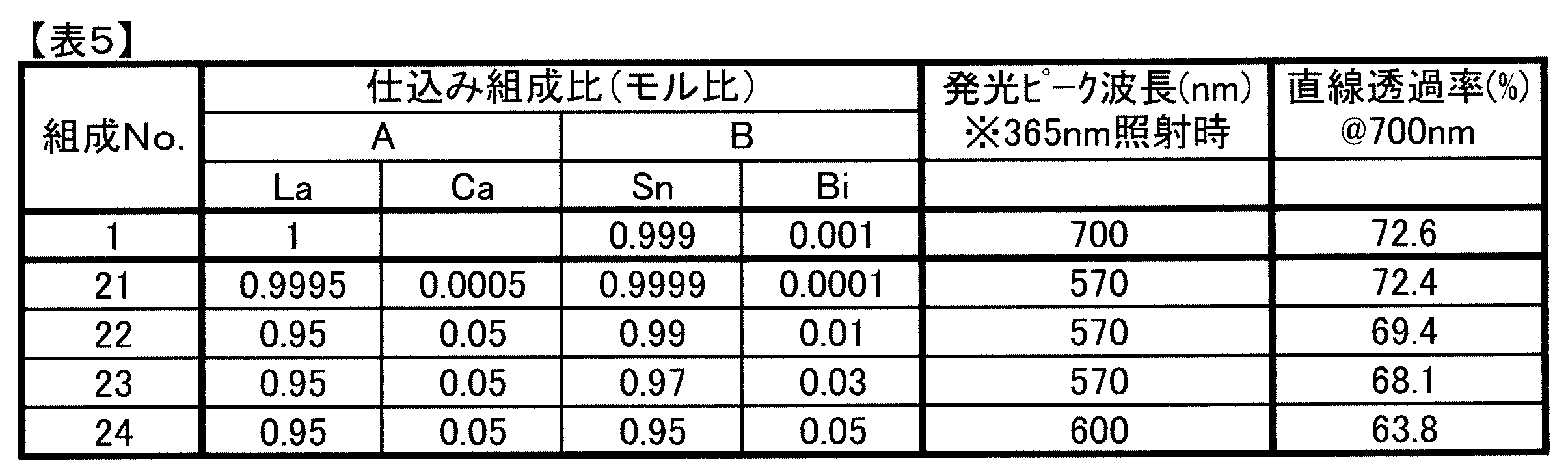
表3から明らかなように、Aサイトに、Mg,Ca,Zn,Sr,Ba,Sc,Ga,In,Yb及びLuからなる群から選択された少なくとも一種の元素としてCaを含有させた場合、組成No.12の場合には、波長シフトが起きていないことがわかる。すなわち、Mg,Ca,Zn,Sr,Ba,Sc,Ga,In,Yb及びLuからなる群から選択された少なくとも一種の元素としてのCaの添加量がAサイトに対して0.05mol%以下では、波長シフトが起きていない。これに対して、Mg,Ca,Zn,Sr,Ba,Sc,Ga,In,Yb及びLuからなる群から選択された少なくとも一種の元素としてのCaの添加量がAサイトに対して0.1mol%以上の場合には、波長シフトが起きている。従って、多様な発光ピーク波長の発光セラミックスを提供することができる。
なお、組成No.20では、Caの含有量がAサイトにおいて20mol%であり、この場合、波長シフトは生じているものの、直線透過率が50%未満と低かった。しかし、組成No.17~19では、Caの含有量がAサイトにおいて10mol%以下であり、この場合、波長シフトが生じつつ、直線透過率が60%以上と高くできる。さらに、組成No.13~16では、Caの含有量がAサイトにおいて1mol%以下であり、この場合、波長シフトが生じつつ、直線透過率が70%以上と高くできる。よって、好ましくは、Mg,Ca,Zn,Sr,Ba,Sc,Ga,In,Yb及びLuからなる群から選択された少なくとも一種の元素としてのCaの添加量は、Aサイトにおいて0.1mol%以上、20mol%未満とすることが望ましい。より好ましくは、Caの添加量は、10mol%以下であることが望ましいことがわかる。さらに好ましくは、Caの添加量は、1mol%以下であることが望ましいことがわかる。
表4の組成No.12と組成No.21との対比から明らかなように、Mg,Ca,Zn,Sr,Ba,Sc,Ga,In,Yb及びLuからなる群から選択された少なくとも一種の元素としてのCaがAサイトにおいて0.05mol%含有されていたとしても、Biの含有量よりも少ない組成No.12では、波長シフトが生じていない。これに対して、組成No.21では、Biの添加量よりもCaの添加量が多いため、波長シフトが生じている。よって、好ましくは、Mg,Ca,Zn,Sr,Ba,Sc,Ga,In,Yb及びLuからなる群から選択された少なくとも一種の元素の含有されたサイトに対する含有量は、BiのBサイトに対する含有量よりも多いことが望ましいことがわかる。
また、表5の組成No.21~24から、Biの含有量を変化させたとしても、Mg,Ca,Zn,Sr,Ba,Sc,Ga,In,Yb及びLuからなる群から選択された少なくとも一種の元素の含有されたサイトに対する含有量がBiのBサイトに対する含有量以上であれば、波長シフトが生じていることがわかる。
よって、波長シフトを生じさせて、様々な発光ピーク波長の発光セラミックスを得るには、Mg,Ca,Zn,Sr,Ba,Sc,Ga,In,Yb及びLuからなる群から選択された少なくとも一種の元素の含有されたAサイトに対する含有量は、0.1mol%以上、あるいはBiのBサイトに対する含有量以上とすることが望ましい。また、光透過率の観点からは、上記Mg,Ca,Zn,Sr,Ba,Sc,Ga,In,Yb及びLuからなる群から選択された少なくとも一種の元素の含有されたAサイトに対する含有量は20mol%未満、より好ましくは10mol%以下であることが望ましい。
(実施例3)
実施例1と同様にして、下記の表6に示す組成No.25~34の評価サンプルを得た。各評価サンプルについて、実施例1と同様に、発光ピーク波長及び直線透過率を求めた。なお、表6においては、組成No.1及び組成No.7の結果も示す。
実施例1と同様にして、下記の表6に示す組成No.25~34の評価サンプルを得た。各評価サンプルについて、実施例1と同様に、発光ピーク波長及び直線透過率を求めた。なお、表6においては、組成No.1及び組成No.7の結果も示す。

表6から明らかなように、BサイトにSnが含まれておれば、Aサイトにおいて、La,GdまたはYのいずれが含有されている場合においても、波長シフトの効果が得られることがわかる。
(実施例4)
実施例1と同様にして、下記の表7~表11に示す組成No.35~62の評価サンプルを得た。実施例1と同様にして、発光ピーク波長及び直線透過率を求めた。結果を表7~表11に併せて示す。
実施例1と同様にして、下記の表7~表11に示す組成No.35~62の評価サンプルを得た。実施例1と同様にして、発光ピーク波長及び直線透過率を求めた。結果を表7~表11に併せて示す。
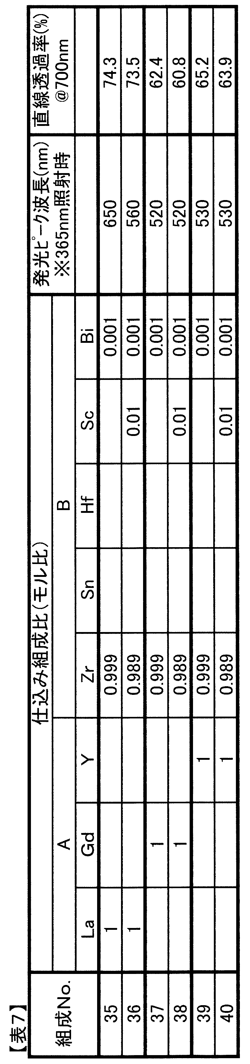

表7の組成No.35と組成No.36の結果から明らかなように、Bサイトの主たる元素がZrの場合、Aサイトの主たる元素がLaの場合に、波長シフトが生じている。これに対して、Bサイトの主たる元素がZrの場合に、Aサイトの主たる元素がGdやYの場合には波長シフトは生じていない。
表8の組成No.41~48の評価結果から明らかなように、BサイトがZrのとき、Aサイトの主たる元素であるLaの含有割合が50mol%以上であれば、波長シフトが生じていることがわかる。
なお、組成No.47と組成No.48との対比では、発光ピーク波長が5nm異なっている。しかしながら、発光ピーク波長の5nmの違いは測定誤差範囲と考えられる。



表9から明らかなように、Bサイトの主たる元素がHfの場合、Aサイトの主たる元素のLaの含有割合が50mol%以上であれば、波長シフトが生じている。
また、表10から明らかなように、Bサイトの主たる元素がZr及びHfの場合、Aサイトの主たる元素のLaが50mol%以上であれば、波長シフトが生じていることがわかる。
表11から明らかなように、SnがBサイトに含有されている場合であれば、Aサイトの主たる元素のLaの含有量が50mol%以上でなくても、波長シフトが生じていることがわかる。
従って、表9~表11から明らかなように、BサイトにSnが含まれておらず、BサイトにZr又はHfのいずれかが含まれている場合、Aサイトの主たる元素のLaが50mol%以上であれば、波長シフトの効果が得られることがわかる。
上記各種元素の添加による波長シフトの原因は定かではないが、以下の通りと考えられる。
添加元素の種類に関係なく、発光ピーク波長の変化が見られるため、添加イオンの価数とその置換サイトの関係が影響している可能性があると思われる。すなわち、通常三価イオンの位置するAサイトへの二価イオンの置換、通常四価イオンの位置するBサイトへの三価イオンの置換が影響している可能性があると考えられる。そこで、実際の評価サンプルにおける添加元素の存在サイトについて検討した。組成No.3及び組成No.11の評価サンプルを例にとり、格子定数からの推測を行った。
まず、LaZrOwをベースに、BサイトのZrをSnで0,5,10,20,50,90,100mol%置換した試料を作製し、その格子定数の実測値をBサイト構成イオンのイオン半径の平均値に対してプロットした。この結果を図2に示す。また、同様にAサイトのLaをYで0,20,50,80mol%置換した試料を作製し、その格子定数の実測値をAサイト構成イオンのイオン半径の平均値に対してプロットした。この結果を図3に示す。ここで、イオン半径の平均値は、各イオンの6配位イオン半径と、そのイオンの構成比率との積をする方法により求めた。なお、イオン半径としては、以下のシャノンの値を求めた。
「Zr4+,Sn4+,La3+,Y3+,Ca2+,Lu3+」の6配位イオン半径=「0.72,0.69,1.032,0.90,1.00,0.86」
図2及び図3から、Bサイト及びAサイトのいずれにおいても、イオン半径の平均値と格子定数はほぼ線形の関係にあり、ベガード則に従っていることがわかる。ここで得られた線形近似の関係式を用いることにより、添加物が特定のサイトの元素に置換した場合の、格子定数の増減量を計算することができる。
組成No.3の評価サンプルにおけるCa、組成No.11の評価サンプルにおけるLuの場合について、それらがAサイトまたはBサイトに1mol%置換した際の格子定数の増減量の推測値と、XRDスペクトルにより実際に求めた値とを比較した。結果を下記の表12に示す。
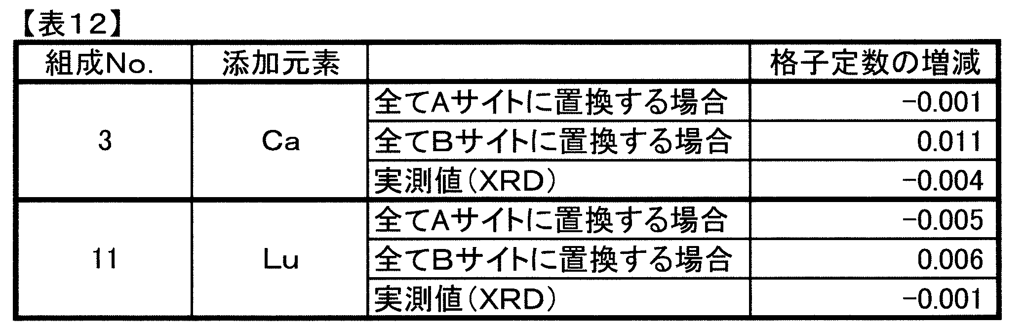
正確な一致は見られないものの、表12から格子定数の減少が見られる評価サンプル組成No.3では、CaはAサイトに置換しており、格子定数の変化がほとんど見られない評価サンプル組成No.11では、LuはAサイト及びBサイトの双方に置換していることが推測される。従って、Aサイトへの二価イオンの置換、Bサイトへの三価イオンの置換が、発光ピーク波長の変化の要因であると考えられる。
なお、上記実施例1~4では、組成No.1~62の評価サンプルを用意したが、この組成No.1~62における各元素の割合は、仕込み組成比におけるモル比である。この仕込み組成比のモル比は、実際に得られた焼結体からなる評価サンプル中における各元素の含有割合としてのモル比と同等である。これは、XRF分析により、得られた焼結体の含有割合により確かめられている。下記の表13に組成No.3及び組成No.11より得られた焼結体である評価サンプルにおける元素含有割合をXRF分析により得た結果を示す。

表1の組成No.3及び表2の組成No.11における各元素の仕込み組成比と、表13における各元素のXRF分析により得られたモル比とが同等であることが分かる。
(実施例5)
前述した組成No.1と、下記の表14に示す組成No.63の評価サンプルを、実施例1と同様にして得た。また、組成No.1及び組成No.63の評価サンプルについて、実施例1と同様にして、発光ピーク波長を求めた。また、格子定数を測定した。結果を下記の表14に併せて示す。
前述した組成No.1と、下記の表14に示す組成No.63の評価サンプルを、実施例1と同様にして得た。また、組成No.1及び組成No.63の評価サンプルについて、実施例1と同様にして、発光ピーク波長を求めた。また、格子定数を測定した。結果を下記の表14に併せて示す。

表14から明らかなように、組成No.1及び組成No.63のいずれの評価サンプルにおいても、発光ピーク波長のシフトは起きていない。
(実施例6)
実施例1と同様にして、下記の表15に示す組成No.35,36,64~71の評価サンプルを得た。実施例1と同様にして、評価サンプルの発光ピーク波長、直線透過率を求めた。また、組成No.35の評価サンプルについては、格子定数を併せて示す。
実施例1と同様にして、下記の表15に示す組成No.35,36,64~71の評価サンプルを得た。実施例1と同様にして、評価サンプルの発光ピーク波長、直線透過率を求めた。また、組成No.35の評価サンプルについては、格子定数を併せて示す。

組成No.35と組成No.36との対比により、Scを含有させた場合にも、発光ピーク波長がシフトし、かつ十分な直線透過率の得られることがわかる。また、組成No.64~69の結果から、Caの場合と同様に、Scを共添加した場合、Scの含有割合が0.1mol%以上であれば、十分な波長シフトが生じることがわかる。また、20mol%を超えると、直線透過率が組成No.69の評価サンプルの場合よりも低くなっていることが確かめられている。また、組成No.70,71の評価サンプルから明らかなように、Scを共添加した場合においても、Biの含有割合が変化すると、発光ピーク波長のシフト量が変化することがわかる。
なお、本発明に係る発光セラミックスでは、最終的に調製により得られたABOWで表されるパイロクロア型化合物からなる発光セラミックスにおいて、各元素はAサイトまたはBサイトに存在している。各元素が、AサイトまたはBサイトのいずれに存在しているかについては、例えば、放射光を用いたXAFS(X-RAY ABSORPTION FINE STRUCTURE)により確認することができる。このXAFSは、元素の存在サイトの情報を得ることができ、定性的な分析に用いられることが多いが、解析により、元素の占用率の定量も可能である。
すなわち、X線領域では、各元素は、内殻遷移に伴った元素固有の吸収を有する。この吸収スペクトルから、着目している元素に配位している原子の種類、数、結合距離、対称性といった情報が得られる。材料中において、所定のサイトに存在することがわかっている元素における情報と、XAFSの測定結果とから、各元素がいずれのサイトに存在するかを知ることができる。
1…波長変換部
2…光源
3…リフレクタ
4…基板
6…波長変換装置
2…光源
3…リフレクタ
4…基板
6…波長変換装置
Claims (9)
- ABOW(ただし、Aは、La,Y及びGdからなる群から選択された少なくとも一種を含み、前記La,Y及びGdからなる群から選択された少なくとも一種を合計で80mol%以上含み、Bは、Zr,Sn及びHfからなる群から選択された少なくとも一種を含み、Wは電気的中性を保つための正の数)100mol%に対し、Biが0.01mol%以上含有されている、パイロクロア型化合物からなる発光セラミックスにおいて、
前記Bは少なくともSnを含み、
さらに、Mg,Ca,Zn,Sr,Ba,Sc,Ga,In,Yb及びLuからなる群から選択された少なくとも一種が含有されている、発光セラミックス。 - ABOW(ただし、Aは、La,Y及びGdからなる群から選択された少なくとも一種を含み、前記La,Y及びGdからなる群から選択された少なくとも一種を合計で80mol%以上含み、Bは、Zr,Sn及びHfからなる群から選択された少なくとも一種を含み、Wは電気的中性を保つための正の数)100mol%に対し、Biが0.01mol%以上含有されている、パイロクロア型化合物からなる発光セラミックスにおいて、
前記Bは少なくともZrまたはHfを含み、
さらに、Mg,Ca,Zn,Sr,Ba,Sc,Ga,In,Yb及びLuからなる群から選択された少なくとも一種が含有されており、
前記Aは少なくともLaを50mol%以上含む、発光セラミックス。 - 前記Mg,Ca,Zn,Sr,Ba,Sc,Ga,In,Yb及びLuからなる群から選択された少なくとも一種の含有量が、合計で0.1mol%以上である、請求項1または2に記載の発光セラミックス。
- 前記Mg,Ca,Zn,Sr,Ba,Sc,Ga,In,Yb及びLuからなる群から選択された少なくとも一種の含有量は、Biの含有量以上である、請求項1または2に記載の発光セラミックス。
- 前記Mg,Ca,Zn,Sr,Ba,Sc,Ga,In,Yb及びLuからなる群から選択された少なくとも一種の含有量は、20mol%未満である、請求項1~4のいずれか1項に記載の発光セラミックス。
- 前記Mg,Ca,Zn,Sr,Ba,Sc,Ga,In,Yb及びLuからなる群から選択された少なくとも一種の含有量は、10mol%以下である、請求項5に記載の発光セラミックス。
- 前記AにMg,Ca,Zn,SrもしくはBaのいずれかが含まれており、または、
前記BにSc,Ga,In,YbもしくはLuのいずれかが含まれている、請求項1または2に記載の発光セラミックス。 - 紫外線を照射されたときの可視域における発光ピーク波長が、前記Mg,Ca,Zn,Sr,Ba,Sc,Ga,In,Yb及びLuからなる群から選択された少なくとも一種が含有されていることにより、前記Mg,Ca,Zn,Sr,Ba,Sc,Ga,In,Yb及びLuからなる群から選択された少なくとも一種が含有されていないことを除いては同じ発光セラミックスの発光ピーク波長に比べて10nm以上異なっている、請求項1または2に記載の発光セラミックス。
- 請求項1~8のいずれか1項に記載の発光セラミックスと、
前記発光セラミックスに紫外線を照射する光源と、を備える、波長変換装置。
Priority Applications (3)
| Application Number | Priority Date | Filing Date | Title |
|---|---|---|---|
| CN201780036281.8A CN109312231B (zh) | 2016-08-12 | 2017-04-12 | 发光陶瓷以及波长变换装置 |
| JP2018533418A JP6899831B2 (ja) | 2016-08-12 | 2017-04-12 | 発光セラミックス及び波長変換装置 |
| US16/204,231 US10689571B2 (en) | 2016-08-12 | 2018-11-29 | Light-emitting ceramic and wavelength conversion device |
Applications Claiming Priority (2)
| Application Number | Priority Date | Filing Date | Title |
|---|---|---|---|
| JP2016158829 | 2016-08-12 | ||
| JP2016-158829 | 2016-08-12 |
Related Child Applications (1)
| Application Number | Title | Priority Date | Filing Date |
|---|---|---|---|
| US16/204,231 Continuation US10689571B2 (en) | 2016-08-12 | 2018-11-29 | Light-emitting ceramic and wavelength conversion device |
Publications (1)
| Publication Number | Publication Date |
|---|---|
| WO2018029906A1 true WO2018029906A1 (ja) | 2018-02-15 |
Family
ID=61161989
Family Applications (1)
| Application Number | Title | Priority Date | Filing Date |
|---|---|---|---|
| PCT/JP2017/014945 Ceased WO2018029906A1 (ja) | 2016-08-12 | 2017-04-12 | 発光セラミックス及び波長変換装置 |
Country Status (4)
| Country | Link |
|---|---|
| US (1) | US10689571B2 (ja) |
| JP (1) | JP6899831B2 (ja) |
| CN (1) | CN109312231B (ja) |
| WO (1) | WO2018029906A1 (ja) |
Cited By (1)
| Publication number | Priority date | Publication date | Assignee | Title |
|---|---|---|---|---|
| WO2019038967A1 (ja) * | 2017-08-24 | 2019-02-28 | 株式会社村田製作所 | 発光セラミックス及び波長変換装置 |
Citations (4)
| Publication number | Priority date | Publication date | Assignee | Title |
|---|---|---|---|---|
| WO2011158580A1 (ja) * | 2010-06-17 | 2011-12-22 | 株式会社村田製作所 | 発光セラミックス、発光素子、シンチレータ及び発光セラミックスの製造方法 |
| JP2012001637A (ja) * | 2010-06-17 | 2012-01-05 | Murata Mfg Co Ltd | 発光セラミックス、発光素子、シンチレータ及び発光セラミックスの製造方法 |
| WO2013058065A1 (ja) * | 2011-10-18 | 2013-04-25 | 株式会社村田製作所 | 発光素子、その製造方法、及び発光デバイス |
| WO2014104143A1 (ja) * | 2012-12-26 | 2014-07-03 | 三菱化学株式会社 | 蛍光体、その蛍光体を用いた蛍光体含有組成物及び発光装置、並びに、その発光装置を用いた画像表示装置及び照明装置 |
Family Cites Families (2)
| Publication number | Priority date | Publication date | Assignee | Title |
|---|---|---|---|---|
| JP2008088349A (ja) * | 2006-10-04 | 2008-04-17 | Sharp Corp | 蛍光体 |
| CN104955787B (zh) * | 2013-01-30 | 2017-06-23 | 株式会社村田制作所 | 发光陶瓷、发光元件及发光器件 |
-
2017
- 2017-04-12 JP JP2018533418A patent/JP6899831B2/ja active Active
- 2017-04-12 WO PCT/JP2017/014945 patent/WO2018029906A1/ja not_active Ceased
- 2017-04-12 CN CN201780036281.8A patent/CN109312231B/zh active Active
-
2018
- 2018-11-29 US US16/204,231 patent/US10689571B2/en active Active
Patent Citations (4)
| Publication number | Priority date | Publication date | Assignee | Title |
|---|---|---|---|---|
| WO2011158580A1 (ja) * | 2010-06-17 | 2011-12-22 | 株式会社村田製作所 | 発光セラミックス、発光素子、シンチレータ及び発光セラミックスの製造方法 |
| JP2012001637A (ja) * | 2010-06-17 | 2012-01-05 | Murata Mfg Co Ltd | 発光セラミックス、発光素子、シンチレータ及び発光セラミックスの製造方法 |
| WO2013058065A1 (ja) * | 2011-10-18 | 2013-04-25 | 株式会社村田製作所 | 発光素子、その製造方法、及び発光デバイス |
| WO2014104143A1 (ja) * | 2012-12-26 | 2014-07-03 | 三菱化学株式会社 | 蛍光体、その蛍光体を用いた蛍光体含有組成物及び発光装置、並びに、その発光装置を用いた画像表示装置及び照明装置 |
Cited By (2)
| Publication number | Priority date | Publication date | Assignee | Title |
|---|---|---|---|---|
| WO2019038967A1 (ja) * | 2017-08-24 | 2019-02-28 | 株式会社村田製作所 | 発光セラミックス及び波長変換装置 |
| US11691921B2 (en) | 2017-08-24 | 2023-07-04 | Murata Manufacturing Co., Ltd. | Light-emitting ceramic and wavelength conversion device |
Also Published As
| Publication number | Publication date |
|---|---|
| JP6899831B2 (ja) | 2021-07-07 |
| CN109312231A (zh) | 2019-02-05 |
| US20190106622A1 (en) | 2019-04-11 |
| US10689571B2 (en) | 2020-06-23 |
| JPWO2018029906A1 (ja) | 2019-03-28 |
| CN109312231B (zh) | 2022-04-08 |
Similar Documents
| Publication | Publication Date | Title |
|---|---|---|
| TWI535826B (zh) | 磷光體組成物、發光裝置以及產生光的方法 | |
| KR101121717B1 (ko) | Eu(2+)-도핑된 규산염 발광체를 갖는 발광물질 | |
| JP5311045B2 (ja) | 透光性セラミック | |
| JP5527413B2 (ja) | 発光セラミックス、発光素子、シンチレータ及び発光セラミックスの製造方法 | |
| JP6899831B2 (ja) | 発光セラミックス及び波長変換装置 | |
| JP5928613B2 (ja) | 発光セラミックス、発光素子及び発光デバイス | |
| CN110832054B (zh) | 发光陶瓷和波长转换装置 | |
| JP5757336B2 (ja) | 発光セラミックス | |
| KR102005613B1 (ko) | 형광체 | |
| US9068117B2 (en) | Phosphor material and light-emitting device | |
| JP5728835B2 (ja) | 発光セラミックス、発光素子、シンチレータ及び発光セラミックスの製造方法 | |
| KR101673060B1 (ko) | 실리콘 질화물 형광체, 이의 제조 방법 및 이를 포함하는 광소자 | |
| KR20140107065A (ko) | 실리콘 산질화물 형광체, 이의 제조 방법 및 이를 포함하는 광소자 | |
| KR20130131432A (ko) | 형광체의 제조 방법 | |
| JP6519746B2 (ja) | 蛍光体材料及び発光装置 | |
| JP2012036305A (ja) | 無機酸化物蛍光体及びその製造方法並びに発光装置 |
Legal Events
| Date | Code | Title | Description |
|---|---|---|---|
| ENP | Entry into the national phase |
Ref document number: 2018533418 Country of ref document: JP Kind code of ref document: A |
|
| 121 | Ep: the epo has been informed by wipo that ep was designated in this application |
Ref document number: 17838982 Country of ref document: EP Kind code of ref document: A1 |
|
| NENP | Non-entry into the national phase |
Ref country code: DE |
|
| 122 | Ep: pct application non-entry in european phase |
Ref document number: 17838982 Country of ref document: EP Kind code of ref document: A1 |