WO2018029759A1 - 極端紫外光生成方法 - Google Patents
極端紫外光生成方法 Download PDFInfo
- Publication number
- WO2018029759A1 WO2018029759A1 PCT/JP2016/073331 JP2016073331W WO2018029759A1 WO 2018029759 A1 WO2018029759 A1 WO 2018029759A1 JP 2016073331 W JP2016073331 W JP 2016073331W WO 2018029759 A1 WO2018029759 A1 WO 2018029759A1
- Authority
- WO
- WIPO (PCT)
- Prior art keywords
- target
- laser beam
- pulse laser
- extreme ultraviolet
- ultraviolet light
- Prior art date
- Legal status (The legal status is an assumption and is not a legal conclusion. Google has not performed a legal analysis and makes no representation as to the accuracy of the status listed.)
- Ceased
Links
Images





Classifications
-
- H—ELECTRICITY
- H05—ELECTRIC TECHNIQUES NOT OTHERWISE PROVIDED FOR
- H05G—X-RAY TECHNIQUE
- H05G2/00—Apparatus or processes specially adapted for producing X-rays, not involving X-ray tubes, e.g. involving generation of a plasma
- H05G2/001—Production of X-ray radiation generated from plasma
- H05G2/008—Production of X-ray radiation generated from plasma involving an energy-carrying beam in the process of plasma generation
- H05G2/0082—Production of X-ray radiation generated from plasma involving an energy-carrying beam in the process of plasma generation the energy-carrying beam being a laser beam
- H05G2/0088—Production of X-ray radiation generated from plasma involving an energy-carrying beam in the process of plasma generation the energy-carrying beam being a laser beam for preconditioning the plasma generating material
-
- H—ELECTRICITY
- H05—ELECTRIC TECHNIQUES NOT OTHERWISE PROVIDED FOR
- H05G—X-RAY TECHNIQUE
- H05G2/00—Apparatus or processes specially adapted for producing X-rays, not involving X-ray tubes, e.g. involving generation of a plasma
Definitions
- This disclosure relates to an extreme ultraviolet light generation method.
- an LPP Laser Produced Plasma
- DPP discharge Produced Plasma
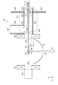
- An extreme ultraviolet light generation method includes a droplet output step of outputting a droplet to a first laser light irradiation region that is a region different from the plasma generation region, and a drop output in the droplet output step
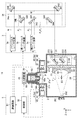
- FIG. 1 is a diagram schematically showing a configuration of an exemplary LPP type EUV light generation system.
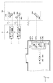
- FIG. 2 is a partial cross-sectional view showing a configuration of an EUV light generation system applicable to the embodiment of the present disclosure.
- FIG. 3 is a partial cross-sectional view showing the configuration of the condensing optical system for the first prepulse laser beam and the second prepulse laser beam.
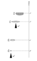
- FIG. 4 is a diagram schematically illustrating a state change of the target material according to the comparative example.
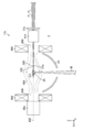
- FIG. 5 is a diagram schematically showing a configuration of an EUV light generation system to which the EUV light generation method according to the first embodiment is applied.
- FIG. 1 is a diagram schematically showing a configuration of an exemplary LPP type EUV light generation system.
- FIG. 2 is a partial cross-sectional view showing a configuration of an EUV light generation system applicable to the embodiment of the present disclosure.
- FIG. 3 is a partial cross-sectional view showing the configuration of the condens
- FIG. 6 is a diagram schematically showing changes in the target material.
- FIG. 7 is a view showing an image obtained by photographing a fragment jet target.
- FIG. 8 is a diagram showing the relationship between the traveling direction of the fragment jet target and the propagation direction of the main pulse laser beam.
- FIG. 9 is a diagram showing the relationship between the density of the target material in the plasma generation region and the irradiation timing of the main pulse laser beam.
- FIG. 10 is a diagram schematically showing a configuration of an EUV light generation system to which the EUV light generation method according to the second embodiment is applied.
- FIG. 11 is a diagram schematically showing the configuration of the first debris suppression device shown in FIG. FIG.
- FIG. 12 is a diagram schematically showing a configuration of an EUV light generation system to which the EUV light generation method according to the third embodiment is applied.
- FIG. 13 is a diagram schematically showing a configuration of an EUV light generation system to which an EUV light generation method according to a modification of the third embodiment is applied.
- FIG. 14 is a diagram schematically showing a configuration of an EUV light generation system to which the EUV light generation method according to the fourth embodiment is applied.
- FIG. 15 is a diagram schematically showing a configuration of an EUV light generation system to which the EUV light generation method according to the fifth embodiment is applied.
- FIG. 1 schematically shows a configuration of an exemplary LPP type EUV light generation system.
- the EUV light generation apparatus 1 may be used with at least one laser apparatus 3.
- a system including the EUV light generation apparatus 1 and the laser apparatus 3 is referred to as an EUV light generation system 11.
- the EUV light generation apparatus 1 includes a chamber 2 and a target supply unit 26.
- the chamber 2 is a container that can be sealed.
- the target supply unit 26 is configured to supply a target material into the chamber 2, and is attached so as to penetrate the wall of the chamber 2, for example.
- the material of the target substance output from the target supply unit 26 may include, but is not limited to, tin, terbium, gadolinium, lithium, xenon, or a combination of any two or more thereof.
- the wall of the chamber 2 is provided with at least one through hole.
- the through hole is closed by the window 21, and the pulse laser beam 32 output from the laser device 3 is transmitted through the window 21.
- an EUV collector mirror 23 having a spheroidal reflecting surface is disposed.
- the EUV collector mirror 23 has first and second focal points.
- the EUV collector mirror 23 may be disposed, for example, such that the first focal point thereof is located in the plasma generation region 25 and the second focal point thereof is located in an intermediate focusing point (IF) 292.
- IF intermediate focusing point
- a through hole 24 is provided at the center of the EUV collector mirror 23, and the pulse laser beam 33 passes through the through hole 24.
- the EUV light generation apparatus 1 includes an EUV light generation controller 5, a target sensor 4, and the like.
- the target sensor 4 is configured to detect one or more of the presence, trajectory, position, and speed of the target 27.
- the target sensor 4 may have an imaging function.
- the EUV light generation apparatus 1 includes a connection portion 29 that allows communication between the inside of the chamber 2 and the inside of the exposure apparatus 6. Inside the connecting portion 29, a wall 291 having an aperture 293 is provided. The wall 291 is arranged such that its aperture 293 is located at the second focal position of the EUV collector mirror 23.
- the EUV light generation apparatus 1 includes a laser light transmission device 34, a laser light focusing mirror 22, a target recovery unit 28 for recovering the target 27, and the like.
- the laser light transmission device 34 includes an optical element for defining the transmission state of the laser light and an actuator for adjusting the position, posture, and the like of the optical element.
- the pulsed laser beam 31 output from the laser device 3 passes through the window 21 as the pulsed laser beam 32 through the laser beam transmission device 34 and enters the chamber 2.
- the pulsed laser light 32 travels in the chamber 2 along at least one laser light path, is reflected by the laser light focusing mirror 22, and is irradiated onto at least one target 27 as pulsed laser light 33.
- the target supply unit 26 is configured to output a target 27 formed of the target material toward the plasma generation region 25 inside the chamber 2.
- the target 27 is irradiated with at least one pulse included in the pulse laser beam 33.
- the target 27 irradiated with the pulse laser beam is turned into plasma, and radiation light 251 is emitted from the plasma.
- the EUV light 252 included in the radiation light 251 is selectively reflected by the EUV collector mirror 23.
- the EUV light 252 reflected by the EUV collector mirror 23 is condensed at the intermediate condensing point 292 and output to the exposure device 6.
- a single target 27 may be irradiated with a plurality of pulses included in the pulse laser beam 33.
- the EUV light generation controller 5 is configured to control the entire EUV light generation system 11.
- the EUV light generation controller 5 is configured to process the detection result of the target sensor 4. Based on the detection result of the target sensor 4, the EUV light generation controller 5 is configured to control, for example, the oscillation timing of the laser device 3, the irradiation direction of the pulse laser light 32, the focusing position of the pulse laser light 33, and the like. Also good.
- the various controls described above are merely examples, and other controls may be added as necessary.
- FIG. 2 is a diagram illustrating a configuration of an EUV light generation system applicable to the embodiment of the present disclosure.
- Each component of the EUV light generation system 11 in the present disclosure can be employed in each step of the extreme ultraviolet light generation method.
- the X direction is defined as a positive direction that penetrates the front surface from the back surface of FIG.
- the Y direction the direction from the target supply unit 26 to the target recovery unit 28 in FIG.
- the Z direction the direction from the EUV collector mirror 23 in FIG.
- the EUV light generation system 11 includes a chamber 2, a laser device 3, a target sensor 4, an EUV light generation controller 5, a target supply unit 26, and a laser light transmission device 34.
- the chamber 2 includes a window 21, a window 21 b at the boundary with the target sensor 4, and a window 21 a at the boundary with the light emitting unit 45.
- a first laser focusing optical system 22a Inside the chamber 2, a first laser focusing optical system 22a, an EUV focusing mirror 23, an EUV focusing mirror holder 81, an EUV focusing mirror holder holding plate 82, and a target recovery unit 28 are provided.
- a second laser focusing optical system 22b (not shown in FIG. 2) is provided in the chamber 2.
- a second laser focusing optical system 22b not shown in FIG. 2 is shown in FIG.
- the first laser focusing optical system 22a includes a first high-reflection off-axis parabolic mirror 221, a first high-reflection flat mirror 222, a first laser focusing optical system holding plate 83, an X direction, a Y direction, And a first stage 84 movable in the Z direction.
- the first laser focusing optical system 22a is arranged so that the focusing position of the first laser focusing optical system 22a coincides with the plasma generation region 25.
- “Match” may include a “substantial match” that may be considered to be a match although it is strictly different.
- the first highly reflective off-axis parabolic mirror 221 is supported by the sixth holder 223.
- the first high reflection flat mirror 222 is supported by the seventh holder 224.
- the target collection unit 28 is disposed on an extension of the track of the droplet 27a. The target collection unit 28 collects the target material that has passed through the first pulse laser irradiation region.
- the chamber 2 includes a target supply unit 26 and a droplet detection device 4a.
- the target supply unit 26 includes a tank 61, a nozzle 62, a heater 63, a piezo element 64, and a pressure regulator 65.
- the tank 61 is formed in a hollow cylindrical shape. A target material is accommodated in the tank 61.
- the tank 61 includes a heater 63.
- the heater 63 is fixed to the outer side surface of the cylindrical shape. The heater 63 heats the tank 61.
- the nozzle 62 has a nozzle hole 62a for outputting a target material.
- the nozzle 62 includes a piezo element 64.
- the piezo element 64 is connected to the control unit 50.
- the nozzle 62 is disposed on the bottom surface of the cylindrical tank 61.
- the nozzle 62 is disposed inside the chamber 2 through the target supply hole 2 a of the chamber 2.
- the target supply hole 2a of the chamber 2 is closed by the target supply unit 26 being arranged.
- One end of the pipe-shaped nozzle 62 is fixed to the hollow tank 61.
- a nozzle hole 62 a is formed at the other end of the pipe-shaped nozzle 62.
- the nozzle hole 62 a is disposed inside the chamber 2.
- the extension of the central axis of the nozzle 62, the first irradiation region of the pre-pulse laser beam P 1 with respect to the droplet 27a is located.
- Irradiation region of the first pre-pulse laser beam P 1. is indicated by a reference numeral 300 in FIG.
- the irradiation region of the first prepulse laser beam P 1 is referred to as a first prepulse laser beam irradiation region 300.
- the droplet detection device 4 a includes a target sensor 4 and a light emitting unit 45.
- the droplet detection device 4a is arranged at a position for detecting that the droplet 27a has passed at the detection position P before the droplet 27a reaches the target generation region.
- the droplet detection device 4a outputs a passage timing signal indicating the timing at which the droplet 27a has passed the detection position P.
- the target sensor 4 and the light emitting unit 45 are disposed on opposite sides of the track of the droplet 27a.
- the target sensor 4 includes an optical sensor 41, a sensor condensing optical system 42, and a sensor container 43.
- the sensor container 43 is disposed outside the chamber 2.
- An optical sensor 41 and a sensor condensing optical system 42 are disposed inside the sensor container 43.
- the light emitting unit 45 includes a light source 46, a light source condensing optical system 47, and a light source container 48.
- the light source container 48 is disposed outside the chamber 2.
- a light source 46 and a light source condensing optical system 47 are arranged inside the light source container 48.
- the pressure regulator 65 communicates with the target supply unit 26 including the tank 61 via the pipe 66.
- the pressure regulator 65 pressurizes the pressure in the tank 61 by supplying gas into the tank 61.
- the pressure regulator 65 reduces the pressure in the tank 61 by discharging gas from the inside of the tank 61.
- An inert gas can be adopted as the gas.
- the EUV light generation system 11 includes a laser device 3, an EUV light generation controller 5, and a laser light transmission device 34 outside the chamber 2.
- the laser device 3 includes a main pulse laser device 3a, a first prepulse laser device 3b, and a second prepulse laser device 3c.
- the first pre-pulse laser beam P 1 is incident on the polarizer 343 as P-polarized light
- the second pre-pulse laser beam P 2 is incident as S-polarized light.
- the main pulse laser device 3a may be a CO 2 laser device.
- Each of the first prepulse laser apparatus 3b and the second prepulse laser apparatus 3c may be a YAG laser apparatus.
- Each of the first pre-pulse laser apparatus 3b and the second pre-pulse laser apparatus 3c may be a laser apparatus using Nd: YVO 4 .
- the YAG laser device includes a laser oscillator and, if necessary, a laser amplifier, and a YAG crystal is used as a laser medium in at least one of the laser oscillator and the laser amplifier.
- the CO 2 laser device includes a laser oscillator and, if necessary, a laser amplifier, and CO 2 gas is used as a laser medium in at least one of the laser oscillator and the laser amplifier.
- the first pre-pulse laser apparatus 3b outputs a first pre-pulse laser beam P 1.
- the first laser light corresponds to the first pre-pulse laser beam P 1 in the present disclosure.
- Second pre-pulse laser device 3c outputs the second pre-pulse laser beam P 2.
- the second laser beam corresponds to the second pre-pulse laser beam P 2 in the present disclosure.
- the main pulse laser device 3a outputs a main pulse laser beam M.
- the third laser beam corresponds to the main pulse laser beam M in the present disclosure.
- the EUV light generation controller 5 includes a control unit 50 and a delay circuit 51.
- Control unit 50 outputs the data for setting the main pulse laser beam M, a first pre-pulse laser beam P 1 and the second delay period of the pre-pulse laser beam P 2.
- Data for setting the delay period of the main pulse laser beam M, the first prepulse laser beam P 1 and the second prepulse laser beam P 2 is input to the delay circuit 51.
- the output of the droplet detection device 4a is input to the delay circuit 51 via the control unit 50.
- the output of the delay circuit 51 is input to the main pulse laser device 3a, the first prepulse laser device 3b, and the second prepulse laser device 3c as a light emission trigger.
- the laser beam transmission device 34 includes a main pulse laser beam transmission device 34a and a pre-pulse laser beam transmission device 34b.
- the main pulse laser beam transmission device 34 a includes a first high reflection mirror 341 and a second high reflection mirror 342.
- the first high reflection mirror 341 is supported by the first holder 346.
- the second high reflection mirror 342 is supported by the second holder 347.
- the first high reflection mirror 341 and the second high reflection mirror 342 are arranged so that the main pulse laser beam M is incident on the first laser focusing optical system 22a.
- the pre-pulse laser beam transmission device 34b includes a third high reflection mirror 340, a polarizer 343, and a fourth high reflection mirror 344.
- the third high reflection mirror 340 is supported by the third holder 345.
- the polarizer 343 is supported by the fourth holder 348.
- the fourth high reflection mirror 344 is supported by the fifth holder 349.
- the polarizer 343 may be a beam splitter that is coated with a film that highly transmits P-polarized light and highly reflects S-polarized light.
- the polarizer 343 may be disposed so that the incident surface and the XY plane coincide with each other in FIG. Polarizer 343, the optical axis of the first pre-pulse laser beam P 1, may be arranged at a position where the optical axis coincides the second pre-pulse laser beam P 2.
- Third high reflecting mirror 340, a polarizer 343 and a fourth high reflective mirror 344, a first pre-pulse laser beam P 1 and the second pre-pulse laser beam P 2 is a second laser beam focusing optics 22b not shown in FIG. 2 It arrange
- First pre-pulse laser beam P 1 and the second pre-pulse laser beam P 2 that is reflected by the high reflection mirror 344 is introduced into the chamber 2 through a window for introducing the first pre-pulse laser beam and the second pre-pulse laser beam
- Window for introducing the first pre-pulse laser beam P 1 and the second pre-pulse laser beam P 2 is indicated by a reference numeral 21c in FIG.
- FIG. 3 is a partial cross-sectional view showing the configuration of the condensing optical system for the first prepulse laser light and the condensing optical system for the second prepulse laser light.
- FIG. 3 shows the XY plane.
- the chamber 2 includes a window 21c for introducing the first prepulse laser beam and the second prepulse laser beam, and a second laser focusing optical system 22b.
- the second laser focusing optical system 22b includes a second high reflection off-axis parabolic mirror 221a, a second high reflection flat mirror 222a, a second laser focusing optical system holding plate 83a, an X direction, a Y direction, And a second stage 84a movable in the Z direction.
- the second highly reflective off-axis parabolic mirror 221a is supported by the eighth holder 223a.
- the second high reflection flat mirror 222a is supported by the ninth holder 224a.
- the second laser focusing optical system 22b is arranged so that the focusing position of the second laser focusing optical system 22b coincides with the first pre-pulse laser beam irradiation region 300.
- the second laser focusing optical system 22b is arranged so that the focusing position of the second laser focusing optical system 22b coincides with the second pre-pulse laser beam irradiation region 302.
- the first prepulse laser beam irradiation region 300 and the second prepulse laser beam irradiation region 302 may overlap at least partially. Fragments jet target generation step, in the present disclosure, the first pre-pulse laser light irradiation area 300 in the modified liquid target reaching the second pre-pulse laser light irradiation area 302 at least partially overlaps the second pre-pulse laser beam P 2 irradiated Embodiments may be included.
- the second laser beam focusing optics 22b is first propagation direction of the pre-pulse laser beam P 1, and a second propagation direction of the pre-pulse laser beam P 2, are arranged perpendicular to the traveling direction of the droplets 27a.
- First propagation direction of the pre-pulse laser beam P 1, and a second propagation direction of the pre-pulse laser beam P 2 may be intersect at traveling direction less than 90 ° angle of the droplet 27a, at an angle greater than 90 ° You may cross.
- a first propagation direction of the pre-pulse laser beam P 1, the second aspect and the propagation direction of the pre-pulse laser beam P 2 coincides shown.
- a first propagation direction of the pre-pulse laser beam P 1 may be read as a second propagation direction of the pre-pulse laser beam P 2.
- the control unit 50 heats the heater 63, heats the target material to a temperature equal to or higher than the melting point of the target material, and melts the target material.
- the melting point is 232 ° C.
- control unit 50 When the control unit 50 receives the droplet generation signal, the control unit 50 transmits a control signal for operating the pressure regulator 65 so that the pressure applied to the target material inside the tank 61 becomes a predetermined pressure. To do. When a predetermined pressure is applied to the target material inside the tank 61, the target material is output from the nozzle 62 at a predetermined speed.
- the control unit 50 sends an electrical signal for operating the piezo element 64 to the piezo element 64 so that the droplet 27a is generated at a predetermined frequency.
- the electric signal sent to the piezo element 64 has a predetermined waveform. As a result, the droplet 27a is generated at a predetermined frequency.
- the droplet detection device 4a outputs a passage timing signal indicating the timing at which the droplet 27a has passed the detection position P.
- the delay circuit 51 receives the passage timing signal output from the droplet detection device 4a via the control unit 50.
- the control unit 50 previously stores in the delay circuit 51 the target delay period data of the first prepulse laser apparatus 3b, the target delay period data of the second prepulse laser apparatus 3c, and the target delay of the main pulse laser apparatus 3a. Send period data.
- a target delay period of the first prepulse laser apparatus 3b is set as a first delay period.
- the target delay period of the second prepulse laser apparatus 3c is set as a second delay period.
- a target delay period of the main pulse laser device 3a is set as a third delay period.
- the first delay period after the droplet 27a has passed the detection position P, the first pre-pulse laser beam irradiation region 300, a first pre-pulse laser beam P 1 is set so as to irradiate the droplet 27a.
- the first delay period starts from the period from when the droplet 27a passes the detection position P to the timing when the droplet 27a reaches the first prepulse laser beam irradiation region 300, and is described later in the first prepulse laser apparatus 3.
- the first pre-pulse laser beam P 1 from the first trigger signal is output to is a period obtained by subtracting the period until reaching the first pre-pulse laser beam irradiation region 300.
- the second delay period, after the first pre-pulse laser beam P 1 is irradiated on the droplet 27a, the second pre-pulse laser beam irradiation region 302, a second pre-pulse laser beam P 2 is irradiated with deformed liquid target Is set as follows.
- the second delay period starts from the period from when the droplet 27a passes the detection position P to the timing at which the deformed liquid target reaches the second prepulse laser light irradiation region 302, and is later described in the second prepulse laser apparatus 3c.
- the second trigger signal is output second pre-pulse laser beam P 2 is a period minus the period until reaching the second pre-pulse laser light irradiation area 302.
- fragments jets target is generated.
- the fragment jet target is illustrated with reference numeral 27f in FIGS.
- the third delay period is based on the timing at which the droplet 27a has passed the detection position P, and from the period up to the timing at which a part of the fragment jet target reaches the plasma generation region 25, the main pulse laser beam transmission device 34a is described later.
- the period from when the third trigger signal is output until the main pulse laser beam M reaches the plasma generation region 25 is subtracted.
- Set value from the controller 50 to the first pre-pulse laser apparatus 3b, the energy and per pulse of the first pre-pulse laser beam P 1 may be a first pulse width of the pre-pulse laser beam P 1.
- Set value from the controller 50 to the second pre-pulse laser device. 3c, energy and per one pulse of the second pre-pulse laser beam P 2 may be a second pulse width of the pre-pulse laser beam P 2.
- the set value from the control unit 50 to the main pulse laser device 3a may be the energy per pulse of the main pulse laser beam M, the pulse width of the main pulse laser beam M, or the pulse waveform of the main pulse laser beam M. .
- the delay circuit 51 transmits a first trigger signal indicating that the first delay period has elapsed with respect to the reception timing of the light emission trigger signal to the first prepulse laser apparatus 3b.
- the first pre-pulse laser device 3b is in accordance with the first trigger signal, and outputs a first pre-pulse laser beam P 1.
- the delay circuit 51 transmits a second trigger signal indicating that the second delay period has elapsed with respect to the reception timing of the light emission trigger signal to the second prepulse laser apparatus 3c.
- the second delay period is a period exceeding the first delay period.
- Second pre-pulse laser device 3c in accordance with the second trigger signal to output a second pre-pulse laser beam P 2.
- the first pre-pulse laser beam P 1 is incident on the third high reflecting mirror 340 as P-polarized light.
- the first pre-pulse laser beam P 1 is reflected with a high reflectance by the third high reflection mirror 340 and enters the polarizer 343.
- the second pre-pulse laser beam P 2 is incident on the polarizer 343 as S-polarized light.
- the second pre-pulse laser beam P 2 is reflected at a high reflectance by the polarizer 343.
- the optical axis of the second prepulse laser beam P 2 reflected by the polarizer 343 coincides with the optical axis of the first prepulse laser beam P 1 .
- the first pre-pulse laser beam P 1 and the second pre-pulse laser beam P 2 is the fourth high reflection mirror 344, is reflected at a high reflectance, enters the second laser beam focusing optics 22b.
- the first pre-pulse laser beam P 1 and the second pre-pulse laser beam P 2 are incident on the second laser beam focusing optics 22b, it is respectively focused at a predetermined focused diameter.
- the first pre-pulse laser beam P 1 condensed to a predetermined focused diameter is irradiated to the droplet 27a.
- deformation liquid target is generated.
- the second pre-pulse laser beam P 2 condensed to a predetermined focused diameter is irradiated to the deformed liquid target.
- fragments jets target is generated.
- the delay circuit 51 transmits a third trigger signal indicating that the third delay period has elapsed with respect to the reception timing of the light emission trigger signal to the main pulse laser device 3a.
- the third delay period is a period exceeding the second delay period.
- the main pulse laser device 3a outputs the main pulse laser beam M according to the third trigger signal.
- the main pulse laser beam M is reflected with high reflectivity by the first high reflection mirror 341 and the second high reflection mirror 342, and enters the first laser focusing optical system 22a via the window 21.
- the main pulse laser beam M incident on the first laser focusing optical system 22a is focused with a predetermined focusing diameter.
- the main pulse laser beam M focused to a predetermined focused diameter is irradiated to the fragment jet target.
- the main pulse laser beam M is irradiated to the fragment jet target, at least a part of the fragment jet target is turned into plasma, and EUV light is emitted from the plasma-formed target material.
- Target is an object to be irradiated with laser light introduced into a chamber.
- Droplet is a form of the target substance output to the inside of the chamber.
- the “deformed liquid target” is a form of target material in which the droplet is deformed into a thick disk shape.
- the deformed liquid target may be a droplet having a concave shape in the center of a thick disk irradiated with pulsed laser light.
- the “disc-shaped dispersion target” is a form of a target material in which a deformed liquid target is pulverized and a large number of minute droplets are dispersed in a disc shape in a direction perpendicular to the propagation direction of the prepulse laser beam.
- Tertiary target is a form of a target material in which microdroplets constituting a disc-shaped dispersion target are pulverized and a large number of microdroplets diffuse in a dome shape.
- the “fragment jet target” is a form of a target material in which a liquid deformation target is pulverized and a large number of fine particles are diffused along the propagation direction of the prepulse laser beam.
- “Debris component” is an unnecessary particle that does not contribute to the radiation of EUV light, such as a fragment of a target substance existing inside the chamber.
- the traveling direction of the fragment jet target is the direction in which the particles of the target material constituting the fragment jet target travel integrally.
- the upstream side in the traveling direction of the fragment jet target is the second pre-pulse laser beam irradiation region side in the route of the fragment jet target.
- the downstream side in the traveling direction of the fragment jet target is the opposite side of the irradiation region of the second pre-pulse laser beam in the fragment jet target path.
- Condensed diameter is the diameter of the cross section orthogonal to the optical axis of the pulsed laser beam in the optical path of the pulsed laser beam at the target irradiation position, and does not necessarily mean the minimum focused diameter at the focal point of the focusing optical system do not do.
- “Laser beam propagation direction” is a direction from the light source to the target along the optical path.
- the direction is from the optical element on the light source side to the optical element on the target side.
- the upstream side in the propagation direction of the pulse laser beam is the light source side in the optical path.
- the downstream side in the propagation direction of the pulse laser beam is the opposite side of the light source in the optical path.
- FIG. 4 is a diagram schematically illustrating a state change of a target material according to a comparative example.
- Figure 4 is a fourth pre-pulse laser beam P 4 is a change in the target material when illuminated, and the fourth pre-pulse laser beam P 4 fifth pre-pulse laser beam P 5 with respect to the target material which is irradiated to the target substance This shows how the target material changes when irradiated with.
- the direction from left to right in FIG. 4 represents the passage of time.
- the fourth prepulse laser beam P 4 is irradiated to the droplet 27 a.
- the pulse width of the fourth pre-pulse laser beam P 4 may be less than 1 nanosecond.
- Frequency of the fourth pre-pulse laser beam P 4 may be between 100 kilohertz.
- Droplets 27a to a fourth pre-pulse laser beam P 4 is irradiated, through a form of deformation liquid target 27b at the timing t 1, a disk-like dispersion target 27c at a timing t 2.
- the pulse width of the fifth pre-pulse laser beam P 5 may be between 1 nanosecond or more.
- micro droplets into a dome shape protruding in the opposite direction to the propagation direction of the fifth pre-pulse laser beam P 5 is in a state of being diffused.
- the micro droplets constituting the tertiary target 27d diffuse almost isotropically in the convex direction.
- the diffusion speed of the micro droplets constituting the tertiary target 27d can be about 100 meters / second to 200 meters / second.
- the EUV light emission described with reference to FIG. 4 has the following problems.
- FIG. 5 is a diagram schematically showing a configuration of an EUV light generation system to which an EUV light generation method according to the first embodiment is applied.
- the extreme ultraviolet light generation method corresponds to the EUV light generation method in the present disclosure.
- the EUV light generation system 11a shown in FIG. 5 includes an EUV collector mirror 23, a target supply unit 26, a target recovery unit 28, and a second target recovery unit 28a.
- the target supply unit 26 is arranged to supply the droplet 27a to the first pre-pulse laser beam irradiation region 300.
- a dashed line denoted by reference numeral 27e indicates a route of the droplet 27a.
- the first laser beam focusing optics 22a shown in Figure 2, the propagation direction of the main pulse laser beam M shown in FIG. 5, a first propagation direction of the pre-pulse laser beam P 1, and the second pre-pulse laser beam P 2 Arranged so as to be orthogonal to the propagation direction.
- Propagation direction of the main pulse laser beam M may be a direction different from the first direction of propagation of the pre-pulse laser beam P 1.
- Direction different from the first direction of propagation of the pre-pulse laser beam P 1 is, for example, may be a direction intersecting the first direction of propagation and 90 ° or less angle of the pre-pulse laser beam P 1.
- Direction different from the first direction of propagation of the pre-pulse laser beam P 1 is, for example, may be a direction intersecting at an angle greater than the propagation direction and 90 ° in the first pre-pulse laser beam P 1.
- Propagation direction of the main pulse laser beam M may be a direction different from the second propagation direction of the pre-pulse laser beam P 2.
- Direction different from the second propagation direction of the pre-pulse laser beam P 2 may be, for example, a direction intersecting with the second direction of propagation and 90 ° or less angle of the pre-pulse laser beam P 2.
- Direction different from the second propagation direction of the pre-pulse laser beam P 2 may be, for example, a direction intersecting at a second angle greater than the propagation direction and 90 ° in the pre-pulse laser beam P 2.
- the plasma generation region 25 are separated by a predetermined distance and the first pre-pulse laser light irradiation area 300.
- the first prepulse laser beam irradiation region 300 is a region different from the plasma generation region 25.
- a second propagation direction of the pre-pulse laser beam P 2, the plasma generation region 25 are separated by a predetermined distance and a second pre-pulse laser light irradiation area 302.
- the second pre-pulse laser beam irradiation region 302 is a region different from the plasma generation region 25.
- the second target collector 28a for collecting the target is located.
- the droplet 27 a output from the target supply unit 26 illustrated in FIG. 5 reaches the first pre-pulse laser beam irradiation region 300.
- the droplet output step corresponds to a step of supplying the droplet 27a from the target supply unit 26 to the first pre-pulse laser beam irradiation region 300 in the present disclosure.
- the first laser light irradiation region corresponds to the first prepulse laser light irradiation region 300 in the present disclosure.
- Droplet 27a that has reached the first pre-pulse laser beam irradiation region 300 is first pre-pulse laser beam P 1 is irradiated.
- Modified liquid target generation step, in the present disclosure, with respect to droplet 27a that has reached the first pre-pulse laser beam irradiation region 300 corresponds to the step of irradiating the first pre-pulse laser beam P 1.
- the deformed liquid target (not shown in FIG. 5), which is the target material irradiated with the first prepulse laser beam P 1, is irradiated with the second prepulse laser beam P 2 in the second prepulse laser beam irradiation region 302.
- the second pre-pulse propagation direction of the laser beam P 2 is a first propagation direction and the same direction of the pre-pulse laser beam P 1.
- the fragment jet target generation step includes a step of irradiating the deformed liquid target with the second pre-pulse laser beam P 2 propagating in the same direction as the propagation direction of the first pre-pulse laser beam P 1 in the present disclosure.
- the second laser light irradiation region corresponds to the second pre-pulse laser light irradiation region 302 in the present disclosure.
- the deformation liquid target reaching the second pre-pulse laser beam irradiation region 302 corresponds to the step of irradiating the second pre-pulse laser beam P 2.
- Fragments jet target 27f travels along a second propagation direction of the pre-pulse laser beam P 2.
- the main pulse laser beam M is applied to the fragment jet target 27f that has reached the plasma generation region 25.
- the fragment jet target 27f irradiated with the main pulse laser beam M is turned into plasma, and EUV light is emitted from the plasma target material.
- the third laser beam irradiation step corresponds to a step of irradiating the main pulse laser beam M to the fragment jet target 27f that has reached the plasma generation region 25 in the present disclosure.
- the first recovery step corresponds to a step of recovering debris components such as fragments remaining after irradiation with the main pulse laser beam M by the second target recovery unit 28a.
- Particles that travel toward the downstream side of the plasma generation region in the propagation direction of the second laser light may include debris components such as fragments remaining after irradiation with the main pulse laser light M.
- FIG. 6 is a diagram schematically showing the change of the target material.
- Figure 6 is state of a change in the target material when the first pre-pulse laser beam P 1 and the second pre-pulse laser beam P 2 is irradiated, and the manner of change of the target material at the time of the main pulse laser beam M is irradiated Represents.
- the first pre-pulse laser beam P 1 is irradiated with droplet 27a, modified liquid target 27b is generated.
- the first pulse width of the pre-pulse laser beam P 1 may be 1.0 nano seconds or more.
- Modified liquid target generating step, to the droplet 27a may include a mode of irradiating the first pre-pulse laser beam P 1 having a 1.0 nano seconds or more pulse width.
- Period of time t 1 from the timing t 0 is a period during which at least part of the deformable liquid target 27b can maintain the state of the droplets.
- the droplet state is a state in which the interface of the deformed liquid target 27b has a single closed curved surface.
- Modified liquid target 27b is in a first propagation direction of the pre-pulse laser beam P 1 having a predetermined thickness, a disk-shaped droplets spread in the direction perpendicular to the first direction of propagation of the pre-pulse laser beam P 1.
- Modified liquid target 27b may include at least one of a shape dented around the position where the shape's first pre-pulse laser beam P 1 is irradiated position recessed, and the first pre-pulse laser beam P 1 is irradiated.
- the second pre-pulse laser beam P 2 is irradiated, the fragment jet target 27f is generated for the modified liquid target 27b .
- the pulse width of the second pre-pulse laser beam P 2 is 100 femtoseconds or can be less than 1.0 nanoseconds.
- Upper limit value of the second pulse width of the pre-pulse laser beam P 2 may be determined in terms of the energy intensity of the second pre-pulse laser beam P 2 the diffusion of the target material becomes insufficient. Upper limit value of the second pulse width of the pre-pulse laser beam P 2, a portion of the target material may be determined in terms of the energy intensity of the second pre-pulse laser beam P 2 is not ionized. Upper limit value of the second pulse width of the pre-pulse laser beam P 2 may be determined in terms of time limitations of the expansion of the target material. Upper limit value of the second pulse width of the pre-pulse laser beam P 2 may be determined in terms of time limitations in the diffusion of the target material.
- Fragments jet target 27f is the second pre-pulse propagation direction of the laser beam P 2, in the form of a target material particles of the target material constituting the fragment jet target 27f are diffused into the jet shape.
- the fragment jet target 27f is in the form of a target material after ions are scattered and ions are lost. Ions may be generated by the irradiation of the first pre-pulse laser beam P 1 for droplet 27a. Ions may be generated by the irradiation of the modified liquid second pre-pulse laser beam P to the target 27b 2.
- the third laser beam irradiation step may include a mode in which the main pulse laser beam M is irradiated to the fragment jet target after the ions are scattered and the ions disappear in the present disclosure.
- FIG. 7 is a view showing an image obtained by photographing a fragment jet target.
- the image of the fragment jet target 27f shown in FIG. 7 is obtained by imaging the fragment jet target 27f actually generated at a certain timing.
- Direction from left to right in FIG. 7 is a second propagation direction of the pre-pulse laser beam P 2.
- a fragment jet target 27f has a high directivity for the second direction of propagation of the pre-pulse laser beam P 2.
- the traveling speed of the fragment jet target 27f obtained by analyzing the image of the fragment jet target 27f shown in FIG. 7 is about 1 kilometer per second to 100 kilometers per second.
- the length in the direction perpendicular to the traveling direction of the fragment jet target 27f is about 100 micrometers.
- the first pre-pulse laser beam P 1 parameter and an example of specification is as follows.
- Diameter of droplet 25 micrometers
- Pulse width of first prepulse laser light 6.0 nanoseconds
- Energy density of first prepulse laser light 4.0 joules per square centimeter
- Condensing diameter of first prepulse laser light 250 micrometers pulse width range: 1.0 ns to 100 ns fluence range: in 0.1 generated from joules per square centimeter of 100 joules per square centimeter fragment jet target 27f, the second pre-pulse laser beam P 2 parameters, and an example of specifications It is as follows.
- Pulse width of second prepulse laser light 14.0 picoseconds
- Energy density of second prepulse laser light 1.0 Joule per square centimeter
- Condensing diameter of second prepulse laser light 300 micrometers
- Delay from first prepulse laser light period 1.0 microsecond pulse width range: 1.0 picosecond to 500 picosecond fluence range: 0.1 joules per square centimeter 100 joules per square centimeter the first pre-pulse laser beam P 1 and the second pre-pulse laser beam P
- the two wavelengths may be equivalent, for example, 1.06 micrometers.
- the second pre-pulse laser device for outputting a second pre-pulse laser beam P 2 may also mode-locked laser as a configuration in which an oscillator . If the pulse width of the second pre-pulse laser beam P 2 is equal to or greater than 150 picoseconds, the second pre-pulse laser device for outputting a second pre-pulse laser beam P 2 may have a structure in which the oscillator of the semiconductor laser.
- the pulse width of the second pre-pulse laser beam P 2 is the same effect as in the case of less than 100 femtoseconds 50 picoseconds expected it can.
- the second pre-pulse laser device for outputting a second pre-pulse laser beam P 2 may apply the playback mode-locked laser.
- a car lens mode lock system can be applied to the second prepulse laser apparatus.
- the first pre-pulse pulse width of the laser beam P 1 is a few nanoseconds or more, if less than a few tens of nanoseconds, the first pre-pulse laser device that outputs a first pre-pulse laser beam P 1 is, have a configuration of applying the Q-switch oscillation Good.
- the first pre-pulse laser device that outputs a first pre-pulse laser beam P 1 may apply the MOPA configuration.
- a semiconductor laser or a CW laser such as an oscillator, by cutting out with a laser beam in time in the optical switch or the like which is disposed on the optical path, to produce a first pre-pulse laser beam P 1 having a desired pulse width.
- MOPA is an abbreviation for Master Oscillator Power Amplifier.
- CW is an abbreviation for Continuous Wave.
- FIG. 8 is a diagram showing the relationship between the propagation direction of the main pulse laser light and the traveling direction of the fragment jet target.
- the traveling direction of the fragment jet target 27f in the present disclosure is consistent with the second direction of propagation of the pre-pulse laser beam P 2 shown in FIG.
- the traveling direction of the fragment jet target 27f may be a first propagation direction of the pre-pulse laser beam P 1.
- the traveling direction of the fragment jet target 27f may be replaced with a second direction of propagation of the pre-pulse laser beam P 2.
- the traveling direction of the fragment jet target 27f may be read as the first direction of propagation of the pre-pulse laser beam P 1.
- the propagation direction of the main pulse laser beam M is parallel to the plus Z direction, and is a direction orthogonal to the traveling direction of the fragment jet target 27f.
- the propagation direction of the main pulse laser beam M may be a direction that intersects the traveling direction of the fragment jet target 27f.
- the third laser beam irradiation step may include a mode in which the main pulse laser beam M propagating in the direction orthogonal to the traveling direction of the fragment jet target 27f in the present disclosure is irradiated.
- FIG. 9 is a diagram showing the relationship between the density of the target material in the plasma generation region and the irradiation timing of the main pulse laser beam.
- the direction from left to right in FIG. 9 represents the passage of time.
- Fragments jet targets 27f generated by the irradiation of the second one of the pre-pulse laser beam P 2 is in the initial state, has a density of optical density over the target material.
- the optimum density of the fragment jet target 27f is the density of the target material optimum for generating EUV light.
- the first pulse M a of the main pulse laser beam M is irradiated, at least a portion of the fragment jet target 27f into a plasma in the plasma generation region 25.
- EUV light is radiated from the plasma-targeted material.
- the density of the target material in the plasma generation region 25 is reduced in accordance with elapse of time. As shown in FIG. 9, the density of the target material in the plasma generation region 25 can be less than the optimum density.
- the target material is moving at high speed in the traveling direction of the fragment jet target 27f. Then, the target material is supplied to the plasma generation region 25 from the upstream side in the traveling direction of the fragment jet target 27f.
- the density of the target material in the plasma generation region 25 can be recovered to an optimum density or higher.
- the density of the target material in the plasma generation region 25 is equal to or higher than the optimum density, it is possible to irradiate the second pulse M b of the main pulse laser beam M. After the irradiation of the second pulse M b of the main pulse laser beam M against fragments jets target 27f undergoes a period until the density of the target material in the plasma generation region 25 is equal to or greater than optimal density, the third main pulse laser beam M irradiation of the pulse M C is possible.
- the main pulse laser beam M may be continuous in time.
- the density of the target material in the plasma generation region 25 may be maintained at an optimum density or higher.
- the decrease in the density of the target material due to the expansion of the target material due to the generation of plasma may be balanced with the increase in the density of the target material due to the movement of the target material in the fragment jet target 27f.
- the third laser beam irradiation step in the present disclosure, the first main pulse laser beam M 1 is irradiated, after the density of the target substance is drilled a period to recover more than the optimum density in the plasma generation region 25, the second main pulse laser beam M 2 may include embodiments to be irradiated.
- a main pulse laser beam having a plurality of pulses, a main pulse laser beam having a long pulse width, or a main pulse laser continuous in time without reducing the conversion efficiency into EUV light due to a decrease in the density of the target material Light can be used.
- the first pre-pulse laser beam irradiation region 300 and the plasma generation region 25 are separated from each other by a predetermined distance. As a result, the trajectory of the subsequent droplets is prevented from being disturbed by the plasma target material, and the positional stability of the droplets 27a in the first pre-pulse laser beam irradiation region 300 can be improved.
- a pulse laser beam having a plurality of pulses separated by a period in which the density of the target material in the plasma generation region 25 is equal to or higher than the optimum density can be used as the main pulse laser beam M.
- the output energy per unit time of EUV light can be improved.
- a fragment jet target 27f which is jet and the target material travels at a high speed is supplied to the plasma generation region 25.
- the initial velocity of the fragment jet target 27f acts as inertia on the debris component such as a fragment remaining after at least a part of the fragment jet target 27f is turned into plasma, and can be recovered in the second target recovery unit 28a. Therefore, adhesion of debris components to the EUV collector mirror 23 can be suppressed.
- FIG. 10 is a diagram schematically illustrating a configuration of an EUV light generation system to which an EUV light generation method according to a second embodiment is applied.
- EUV light generation system 11b shown in FIG. 10 the first optical path of the pre-pulse laser beam P 1 and the second pre-pulse laser beam P 2 inside the chamber 2 comprises a first solenoid magnet 400 and the second solenoid magnet 402 .
- the EUV light generation system 11 b includes a first solenoid magnet 400 and a second solenoid magnet 402.
- the first solenoid magnet 400 and the second solenoid magnet 402 a first propagation direction of the pre-pulse laser beam P 1, and the second propagation direction of the pre-pulse laser beam P 2, the EUV collector mirror 23 across the EUV collector mirror 23 Arranged on both sides.
- the first solenoid magnet 400, a first propagation direction of the pre-pulse laser beam P 1, and the second pre-pulse propagation direction of the laser beam P 2, is positioned upstream of the position of the EUV collector mirror 23.
- the second solenoid magnet 402, the first pre-pulse propagation direction of the laser light P 1, and the second pre-pulse propagation direction of the laser beam P 2, is disposed on the downstream side of the position of the EUV collector mirror 23.
- a magnetic field is generated between the first solenoid magnet 400 and the second solenoid magnet 402.
- a broken line denoted by reference numeral 404 represents a magnetic field line of a magnetic field generated between the first solenoid magnet 400 and the second solenoid magnet 402.
- a broken-line arrow denoted by reference numeral 404 represents the direction of the magnetic field.
- the first solenoid magnet 400 is formed with a first through-hole 406 that allows the first pre-pulse laser beam P 1 , the second pre-pulse laser beam P 2, and the debris component of the target material to pass therethrough.
- the second solenoid magnet 402 has a second through hole 408 through which particles such as a debris component of the target material can pass.
- the propagation direction of the first prepulse laser light P 1 and the propagation direction of the second prepulse laser light P 2 may be parallel to the magnetic field axis 405 of the magnetic field generated by the first solenoid magnet 400 and the second solenoid magnet 402.
- the propagation direction of the main pulse laser beam M is the same direction as the direction of the condensing axis 23a of the EUV collector mirror 23.
- the EUV light generation system 11b includes a first debris suppression device 414.
- the first debris suppression device 414, a first propagation direction of the pre-pulse laser beam P 1, and the second propagation direction of the pre-pulse laser beam P 2, and the window 21c, is disposed at a position between the first solenoid magnet 400 .
- the second target collector 28a is disposed downstream of the position of the second solenoid magnet 402, downstream of the position of the second solenoid magnet 402, the second target collector 28a is disposed.
- the first introduction window corresponds to the first pre-pulse laser beam P 1 and the second window 21c for introducing the pre-pulse laser beam P 2.
- the second introduction window corresponds to the first pre-pulse laser beam P 1 and the second window 21c for introducing the pre-pulse laser beam P 2.
- the first introduction window and the second introduction window are shared.
- a debris component of the target material may be generated.
- some of charged particles such as ions move along the magnetic field lines 404.
- the debris component is induced toward the second through hole 408 of the second solenoid magnet 402 by the action of the magnetic field.
- the debris component guided toward the second through hole 408 of the second solenoid magnet 402 is recovered by the second target recovery unit 28a.
- the initial velocity of the fragment jet target 27f acts as inertia on electrically neutral particles such as neutral atoms and fragments, and heads toward the second target recovery unit 28a. Electrically neutral particles such as fragments are recovered by the second target recovery unit 28a.
- the first recovery step may include a step of recovering particles such as debris components directed toward the second target recovery unit 28a.
- the debris component directed toward the first solenoid magnet 400 passes through the first through hole 406 of the first solenoid magnet 400 and is collected by the first debris suppression device 414.
- the magnetic field generation step corresponds to a step of generating a magnetic field between the first solenoid magnet 400 and the second solenoid magnet 402 in the present disclosure.
- FIG. 11 is a partial cross-sectional view schematically showing the configuration of the first debris suppression device shown in FIG.
- the first debris suppression device 414 illustrated in FIG. 11 includes a gas introduction unit 422, a laser light path tube 424, and a discharge tube 426.
- the discharge pipe 426 communicates with the first discharge port 428.
- the laser beam path tube 424 communicates with the introduction port 430.
- a curve with an arrow denoted by reference numeral 432 represents the flow of the gas introduced from the gas introduction unit 422 into the laser optical path tube 424.
- a curve with an arrow denoted by reference numeral 434 represents a gas flow from the EUV collector mirror 23 side toward the first debris suppression device 414 side.
- the first discharge port 428 is arranged on the introduction port 430 side of the laser optical path tube 424, but the first discharge port 428 is limited to the arrangement shown in FIG. 11. Not.
- the first outlet 428 if disposed the traveling direction of the gas introduced through the gas inlet 422, directed towards away from the first pre-pulse laser beam P 1 and the second window 21c for introducing the pre-pulse laser beam P 2 Good.
- An exhaust device such as a pump may be connected to the first discharge port 428.
- FIG. 11 shows two gas inlets 422, but three or more gas inlets 422 may be provided.
- the gas introduction part 422 may include a ring-shaped slit disposed around the window 21c.
- the particles diffused inside the chamber 2 may include charged particles such as ions.
- the particles diffused into the chamber 2 may include neutral atoms diffused into the gas inside the chamber 2 or electrically neutral particles such as fragments.
- the first debris suppression device 414 introduces gas in a direction from the gas introduction unit 422 toward the laser optical path tube 424.
- the pressure of the gas introduced from the gas introduction unit 422 inside the laser optical path tube 424 may be a pressure at which particles such as debris components that have flowed into the laser optical path tube 424 are stationary inside the laser optical path tube 424.
- the pressure of the gas introduced from the gas introduction unit 422 inside the laser optical path tube 424 is such that particles such as debris components that have flowed into the laser optical path tube 424 are caused by the gas flow inside the laser optical path tube 424. It can be the pressure that flows to one outlet 428.
- Particles such as debris components that have flowed into the laser light path tube 424 through the introduction port 430 are stationary inside the laser light path tube 424 and are discharged from the first discharge port 428.
- a 2nd collection process is equivalent to the process of collect
- first propagation direction of the pre-pulse laser beam P 1 and the second propagation direction of the pre-pulse laser beam P 2, disposing a first solenoid magnet 400 on the upstream side of the position of the EUV collector mirror 23. Further, the second solenoid magnet 402 is disposed at a position downstream of the EUV collector mirror 23. First propagation direction of the pre-pulse laser beam P 1, and generates a magnetic field oriented in the direction parallel to the second direction of propagation of the pre-pulse laser beam P 2.
- a first propagation direction of the pre-pulse laser beam P 1 and particles of debris components such as traveling in a second direction of propagation of the pre-pulse laser beam P 2 Can be recovered.
- the first debris suppression device 414 is disposed at a position upstream of the EUV collector mirror 23 with respect to the propagation direction of the first prepulse laser beam P 1 and the propagation direction of the second prepulse laser beam P 2 . Thereby, particles, such as a debris component which flowed in toward the window 21c, can be collected.
- FIG. 12 is a diagram schematically illustrating a configuration of an EUV light generation system to which an EUV light generation method according to a third embodiment is applied.
- EUV light generation system 11c shown in FIG. 12 through the through-hole 24 provided in a central portion of the EUV collector mirror 23 is irradiated with the first pre-pulse laser beam P 1 and the second pre-pulse laser beam P 2, A laser device (not shown) is provided.
- EUV light generation system 11c shown in FIG. 12 illuminates the first main pulse laser beam M 1 and the second main pulse laser beam M 2, a laser device (not shown), and a main pulse laser beam transmission device (not shown) Prepare.
- the first main pulse laser beam M 1 and the second main pulse laser beam M 2 are a plurality of main pulse laser beam M incident from different directions.
- the first main pulse laser beam M 1 and the second main pulse laser beam M 2 may be output from a single laser device, it may be output from the different laser devices.
- the first main pulse propagation direction of the laser beam M 1, and a second propagation direction of the main pulse laser beam M 2 is a direction perpendicular to the traveling direction of the fragment jet target 27f.
- the first main pulse propagation direction of the laser beam M 1, and second main pulse propagation direction of the laser beam M 2 may be intersect at traveling direction less than 90 ° angle fragments jet targets 27f, a 90 ° You may cross at an angle that exceeds.
- a first propagation direction of the main pulse laser beam M 1, and second propagation direction of the main pulse laser beam M 2 may be parallel and opposite.
- a first propagation direction of the main pulse laser beam M 1, and second propagation direction of the main pulse laser beam M 2, may be a direction crossing.
- the first main pulse laser beam M 1 and the second main pulse laser beam M 2 may be irradiated to the same position in the travel direction of the fragment jet targets 27f of the plasma generation region 25, and is irradiated on different positions May be.
- the first main pulse laser beam M 1 and the second main pulse laser beam M 2 may be irradiated simultaneously to a fragment jet target 27f.
- the second main pulse laser beam M 2 includes, between the first main pulse laser beam M 1, delay times of less than the pulse width of the first main pulse laser beam M 1 may be present.
- the first main pulse laser beam M 1 and the second main pulse laser beam M 2 is to the beam profile may be the same in the plasma generation region 25 may be different from the beam profile in the plasma generation region 25.
- the first main pulse laser beam M 1 and the second main pulse laser beam M 2 are to condensing diameter may be the same in the plasma generation region 25 may be focused diameter is different in the plasma generation region 25 .
- the third laser beam irradiation step may include a mode of irradiating the fragment jet targets 27f, the first main pulse laser beam M 1 and the second main pulse laser beam M 2.
- 7.3 is an operation and effect a plurality of main pulse laser beam, the first main pulse laser beam M 1 and the second main pulse laser beam M 2 is irradiated against fragments jets target 27f from different directions. Thereby, the radiation of EUV light in the plasma generation region 25 is made uniform.
- FIG. 13 is a diagram schematically showing a configuration of an EUV light generation system to which an EUV light generation method according to a modification of the third embodiment is applied.
- the EUV light generation system 11d shown in FIG. 13 five main pulse laser beams M are used.
- the direction passing through the front surface from the back surface of FIG. 13 is the traveling direction of the fragment jet target 27f.
- the direction penetrating the front surface from the back surface of FIG. 13 is the plus Z direction.
- the EUV light generation system 11d includes a sixth laser device 500, a seventh laser device 502, an eighth laser device 504, a ninth laser device 506, and a tenth laser device 508.
- the EUV light generation system 11d includes a sixth main light transmission device 510, a seventh main light transmission device 512, an eighth main light transmission device 514, a ninth main light transmission device 516, and a tenth main light transmission device 518.
- Each of the sixth main light transmission apparatus 510 to the tenth main light transmission apparatus 518 includes at least one of one or more position adjustment mirrors and one or more condensing optical systems.
- the sixth main light transmission apparatus 510 includes a position adjustment mirror 510a and a condensing optical system 510b. It should be noted that the reference numerals of the position adjusting mirror and the condensing optical system of the seventh main light transmission device 512, the eighth main light transmission device 514, the ninth main light transmission device 516, and the tenth main light transmission device 518 are omitted. .
- the sixth main light transmission device 510 focuses the sixth main pulse laser beam M 6 output from the sixth laser device 500 on the plasma generation region 25.
- the seventh main light transmission device 512 focuses the seventh main pulse laser beam M 7 output from the seventh laser device 502 on the plasma generation region 25.
- the eighth main light transmission device 514 focuses the eighth main pulse laser beam M 8 output from the eighth laser device 504 on the plasma generation region 25.
- the ninth main light transmission device 516 focuses the ninth main pulse laser beam M 9 output from the ninth laser device 506 on the plasma generation region 25.
- the tenth main light transmission device 518 focuses the tenth main pulse laser beam M 10 output from the tenth laser device 508 on the plasma generation region 25.
- the EUV light generation system 11d may include a sixth damper 520, a seventh damper 522, an eighth damper 524, a ninth damper 526, and a tenth damper 528.
- the sixth damper 520, the propagation direction of the sixth main pulse laser beam M 6, are disposed on the opposite side of the sixth main optical transmission device 510 across the plasma generation region 25.
- the sixth damper 520 may be disposed on the inner wall of the chamber 2 or may be disposed outside the chamber 2 with a window disposed on the inner wall of the chamber 2 interposed therebetween.
- the same arrangement as that of the sixth damper 520 can be applied.
- the sixth damper 520 absorbs sixth main pulse laser beam M 6 passing through the plasma generation region 25 without being emitted to the target material.
- the seventh damper 522, the eighth damper 524, the ninth damper 526, and the tenth damper 528 have the same functions as the sixth damper 520.
- the third laser beam irradiation step may include a mode of irradiating the fragment jet targets 27f, a tenth main pulse laser beam M 10 from the sixth main pulse laser beam M 6.
- FIG. 14 is a partial cross-sectional view schematically showing a configuration of an EUV light generation system to which an EUV light generation method according to a fourth embodiment is applied.
- the EUV light generation system 11e shown in FIG. 14 includes a grazing incidence collector 600 instead of the EUV collector mirror 23 shown in FIG.
- the oblique incidence concentrator 600 may adopt a known configuration.
- the EUV light generation system 11e includes a debris trap mechanism 602 and a second debris collection unit 604.
- the debris trap mechanism 602 is disposed inside the vessel 2a.
- the debris trap mechanism 602 is disposed between the plasma generation region 25 and the oblique incidence collector 600 in the traveling direction of the fragment jet target 27f.
- the debris trap mechanism 602 can adopt a known configuration.
- the traveling direction of the fragment jet target 27f in the EUV light generation system 11e is the minus Z direction.
- the second debris collection unit 604 is disposed at a position downstream of the plasma generation region 25 in the traveling direction of the fragment jet target 27f.
- the second debris collection unit 604 includes a second discharge port 606 on the opposite side of the vessel 2a.
- the EUV light generation system 11e includes a gas introduction unit (not shown) that introduces gas into the vessel 2a.
- the flow direction of the gas inside the vessel 2a is a direction from the intermediate condensing point 292 side toward the second debris collection unit 604 side.
- An arrow line denoted by reference numeral 610 indicates a gas flow direction inside the vessel 2a.
- EUV light generation system 11e is provided with a first pre-pulse laser beam P 1 and the second pre-pulse laser beam P 2 laser device for outputting, and the second pre-pulse laser beam transmission apparatus 34d.
- the first pre-pulse laser beam P 1 and the second pre-pulse laser beam P 2 through the second pre-pulse laser beam transmission device 34d, and enters from the side of the intermediate focus 292 toward the side of the second debris collection unit 604 .
- the second prepulse laser beam transmission device 34d is arranged inside the vessel 2a.
- EUV light generation system 11e is provided with a laser device for outputting a main pulse laser beam M to the first propagation direction of the pre-pulse laser beam P 1, and the propagation direction and a direction perpendicular to the second direction of propagation of the pre-pulse laser beam P 2 .
- Propagation direction of the main pulse laser beam M, a first propagation direction of the pre-pulse laser beam P 1, and the second may be intersect at the direction of propagation and 90 ° or less angle of the pre-pulse laser beam P 2, greater than 90 ° You may cross at an angle.
- the initial velocity of the fragment jet target 27f acts as inertia on a part of particles such as a debris component after at least a part of the fragment jet target 27f is turned into plasma, and moves toward the second debris collection unit 604. On the other hand, it is collected by the second debris collection unit 604. Part of particles such as a debris component that does not travel toward the second debris collection unit 604 is collected by the debris trap mechanism 602.
- Some of the particles such as debris components that do not go toward the second debris collection unit 604 are flowed toward the second debris collection unit 604 due to the gas flow inside the vessel 2a.
- Part of particles such as debris components that have flowed toward the second debris collection unit 604 and part of particles such as debris components not directed toward the debris trap mechanism 602 are collected by the second debris collection unit 604. Is done.
- Particles such as a debris component collected by the second debris collection unit 604 are discharged to the outside of the vessel 2a through the second discharge port 606.
- Modified liquid target generation step in the present disclosure, is irradiated from the opposite side of the first pre-pulse laser light irradiation area 300 across the grazing incidence collector 600, the first pre-pulse laser beam P 1 with respect to droplet 27a aspect Can be included.
- Fragments jet target generation step in the present disclosure, is irradiated from the opposite side of the second pre-pulse laser light irradiation area 302 across the grazing incidence collector 600, a second pre-pulse laser beam P 2 against deformation liquid target aspect Can be included.
- the third laser beam irradiation step in the present disclosure, the main pulse in the second direction of propagation of the pre-pulse laser beam P 2, with respect to fragment jet target 27f reaching the downstream side of the plasma generation region 25 of the grazing incidence collector 600
- An aspect in which the laser beam M is irradiated may be included.
- the first recovery step may include a step of recovering debris components by the second debris recovery unit 604 in the present disclosure.
- An oblique incidence collector 600 is provided instead of the EUV collector mirror 23. Inside the vessel 2a, gas is supplied in the flow direction from the intermediate condensing point 292 and the oblique incidence concentrator 600 side toward the plasma generation region 25 side. Thereby, the traveling direction of the fragment jet target 27f and the direction of the gas flow inside the vessel 2a are set to be directions away from the oblique incident collector 600, and particles such as the debris component are obliquely incident and condensed. Moving toward the vessel 600 can be suppressed.
- the discharge port for discharging particles such as debris components to the outside of the vessel 2a and the discharge port for discharging the gas inside the vessel 2a can be shared.
- FIG. 15 is a partial cross-sectional view schematically illustrating a configuration of an EUV light generation system to which an EUV light generation method according to a fifth embodiment is applied.
- the EUV light generation system 11f illustrated in FIG. 15 includes an EUV light generation unit 700 and a fragment jet target generation unit 702.
- the fragment jet target generation unit 702 includes a target supply unit 26, a target recovery unit 28, a window 21c, a second debris suppression device 710, a divergence adjustment device 712, and a pulse extraction device 714.
- the divergence adjusting device 712 and the pulse cutting device 714 are arranged at positions downstream of the first pre-pulse laser light irradiation region 300 in the traveling direction of the fragment jet target 27f.
- the divergence adjusting device 712 and the pulse cutting device 714 are arranged in the order of the divergence adjusting device 712 and the pulse cutting device 714 from the upstream side in the traveling direction of the fragment jet target 27f.
- the fragment jet target generation unit 702 includes a target output unit 716.
- the target output unit 716 outputs the pulsed third fragment jet target 27h.
- the third fragment jet target 27h is cut out to a predetermined length in the traveling direction of the fragment jet target 27f.
- the predetermined length of the fragment jet target 27f is less than the length when the fragment jet target 27f is generated.
- the EUV light generation unit 700 includes a vessel 2b, a window 21, an EUV collector mirror 23, and a second target recovery unit 28a.
- the EUV light generation unit 700 includes a target introduction unit 720 that introduces the third fragment jet target 27 h output from the fragment jet target generation unit 702.
- fragment jet target generation unit 702 by irradiating a first pre-pulse laser beam P 1 and the second pre-pulse laser beam P 2 with respect to droplet 27a, to produce a fragment jet target 27f.
- Fragments jet target 27f has a first propagation direction of the pre-pulse laser beam P 1, and travels along a second propagation direction of the pre-pulse laser beam P 2.
- the second debris suppression device 710 collects particles such as debris components that travel toward the window 21c.
- the divergence adjusting device 712 suppresses diffusion of the fragment jet target 27f in the direction of the condensed diameter.
- the second fragment jet target 27g of diffusion in the direction of Atsumariko ⁇ is suppressed, the first propagation direction of the pre-pulse laser beam P 1, and travels along a second propagation direction of the pre-pulse laser beam P 2.
- the pulse cutting device 714 cuts out the fragment jet target 27f to a predetermined length in the traveling direction of the second fragment jet target 27g, and generates a pulsed third fragment jet target 27h.
- the third fragment jet target 27h is introduced into the EUV light generation unit 700 via the target output unit 716 and the target introduction unit 720.
- the main pulse laser beam M is irradiated onto the third fragment jet target 27h.
- the main pulse laser beam M is irradiated to the third fragment jet target 27h, at least a part of the third fragment jet target 27h is turned into plasma, and EUV light is emitted from the plasma-formed target material.
- the divergence adjusting device 712 and the pulse cutting device 714 may be omitted, and the fragment jet target 27f may be introduced into the EUV light generation unit 700.
- the initial speed of the fragment jet target 27f acts as inertia on the debris component generated when the third fragment jet target 27h is turned into plasma, and heads toward the second target recovery unit 28a.
- the debris component heading toward the second target recovery unit 28a is recovered by the second target recovery unit 28a.
- the first recovery step may include a step of recovering particles such as debris components directed toward the second target recovery unit 28a.
- Modified liquid target generation step may include a manner of irradiating the plasma generation region 25 and separated droplets 27a first pre-pulse laser beam P 1 with respect to reaching the first pre-pulse laser light irradiation area 300 .
- Fragments jet target generation step may include a manner of irradiating the second pre-pulse laser beam P 2 against deformation liquid target reaching the second pre-pulse laser light irradiation area 302 is separated from the plasma generation region 25 .
- the divergence adjusting step corresponds to a step of generating the second fragment jet target 27g in which the diffusion in the direction of the condensed diameter of the fragment jet target 27f by the divergence adjusting device 712 in the present disclosure is suppressed.
- the cutting step corresponds to a step of generating the third fragment jet target 27h by cutting the second fragment jet target 27g into a predetermined length by the pulse cutting device 714 in the present disclosure.
- the EUV generation unit and the fragment jet target generation unit 702 are spatially separated. Thereby, contamination of the EUV collector mirror 23 due to debris components generated when the droplet 27a, the particles bounced from the target recovery unit 28, and the fragment jet target 27f are generated can be suppressed.
- the distance from the target supply unit 26 to the first prepulse laser light irradiation region 300 can be shortened, and the positional stability of the droplet 27a in the first prepulse laser light irradiation region 300 can be improved.
- the divergence adjusting device 712 By providing the divergence adjusting device 712, the diffusion of the fragment jet target 27f in the diameter direction can be suppressed.
- the pulse cutting device 714 By providing the pulse cutting device 714, the length of the fragment jet target 27f in the traveling direction of the fragment jet target 27f can be adjusted. As a result, the entry of target components that do not contribute to the radiation of EUV light into the plasma generation region 25 can be suppressed, and the generation of debris components after at least a part of the fragment jet target 27f is turned into plasma can be suppressed.
Landscapes
- Physics & Mathematics (AREA)
- Optics & Photonics (AREA)
- Engineering & Computer Science (AREA)
- Plasma & Fusion (AREA)
- X-Ray Techniques (AREA)
- Exposure And Positioning Against Photoresist Photosensitive Materials (AREA)
Abstract
本開示の一観点に係る極端紫外光生成方法は、プラズマ生成領域と異なる領域である第1レーザ光照射領域にドロップレットを出力し、第1レーザ光照射領域に到達したドロップレットに対して、第1レーザ光を照射して変形液体ターゲットを生成し、プラズマ生成領域と異なる領域である第2レーザ光照射領域に到達した変形液体ターゲットに対して、第2レーザ光を照射してフラグメントジェットターゲットを生成し、プラズマ生成領域に到達したフラグメントジェットターゲットの少なくとも一部に対して、第2レーザ光の伝搬方向と交差する方向に伝搬する第3レーザ光を照射する。
Description
本開示は、極端紫外光生成方法に関する。
近年、半導体プロセスの微細化に伴って、半導体プロセスの光リソグラフィにおける転写パターンの微細化が急速に進展している。次世代においては、20nm以下の微細加工が要求されるようになる。このため、波長13nm程度の極端紫外(EUV;Extreme Ultra Violet)光を生成するための装置と縮小投影反射光学系とを組み合わせた露光装置の開発が期待されている。
EUV光生成装置としては、ターゲット物質にレーザ光を照射することによって生成されるプラズマが用いられるLPP(Laser Produced Plasma)式の装置と、放電によって生成されるプラズマが用いられるDPP(Discharge Produced Plasma)式の装置と、軌道放射光が用いられるSR(Synchrotron Radiation)式の装置との3種類の装置が提案されている。
本開示の1つの観点に係る極端紫外光生成方法は、プラズマ生成領域と異なる領域である第1レーザ光照射領域にドロップレットを出力するドロップレット出力工程と、ドロップレット出力工程において出力されたドロップレットであり、第1レーザ光照射領域に到達したドロップレットに対して、第1レーザ光を照射して変形液体ターゲットを生成する変形液体ターゲット生成工程と、変形液体ターゲット生成工程において生成された変形液体ターゲットであり、プラズマ生成領域と異なる領域である第2レーザ光照射領域に到達した変形液体ターゲットに対して、第2レーザ光を照射してフラグメントジェットターゲットを生成するフラグメントジェットターゲット生成工程と、フラグメントジェットターゲット生成工程において生成されたフラグメントジェットターゲットであり、プラズマ生成領域に到達したフラグメントジェットターゲットの少なくとも一部に対して、第2レーザ光の伝搬方向と交差する方向に伝搬する第3レーザ光を照射する第3レーザ光照射工程と、を含む極端紫外光生成方法である。
本開示のいくつかの実施形態を、単なる例として、添付の図面を参照して以下に説明する。
図1は例示的なLPP式のEUV光生成システムの構成を概略的に示す図である。
図2は本開示の実施形態に適用可能なEUV光生成システムの構成を示す一部断面図である。
図3は第1プリパルスレーザ光及び第2プリパルスレーザ光の集光光学系の構成を示す一部断面図である。
図4は比較例に係るターゲット物質の状態変化を模式的に表す図である。
図5は第1実施形態に係るEUV光生成方法が適用されるEUV光生成システムの構成を概略的に示す図である。
図6はターゲット物質の変化を模式的に示す図である。
図7はフラグメントジェットターゲットを撮影した画像を示す図である。
図8はフラグメントジェットターゲットの進行方向とメインパルスレーザ光の伝搬方向との関係を示す図である。
図9はプラズマ生成領域におけるターゲット物質の密度とメインパルスレーザ光の照射タイミングとの関係を示す図である。
図10は第2実施形態に係るEUV光生成方法が適用されるEUV光生成システムの構成を概略的に示す図である。
図11は図10に示した第1デブリ抑制装置の構成を概略的に示す図である。
図12は第3実施形態に係るEUV光生成方法が適用されるEUV光生成システムの構成を概略的に示す図である。
図13は第3実施形態の変形例に係るEUV光生成方法が適用されるEUV光生成システムの構成を概略的に示す図である。
図14は第4実施形態に係るEUV光生成方法が適用されるEUV光生成システムの構成を概略的に示す図である。
図15は第5実施形態に係るEUV光生成方法が適用されるEUV光生成システムの構成を概略的に示す図である。
-目次-
1.極端紫外光生成システムの全体説明
1.1 構成
1.2 動作
2.第1レーザ光、第2レーザ光及び第3レーザ光をターゲットに照射するEUV光生成システムの説明
2.1 構成
2.2 動作
3.用語の説明
4.課題
5.第1実施形態
5.1 構成
5.2 動作
5.3 ターゲット物質の状態変化
5.4 メインパルスレーザ光
5.5 作用・効果
6.第2実施形態
6.1 構成
6.2 動作
6.3 デブリ抑制装置
6.4 作用・効果
7.第3実施形態
7.1 構成
7.2 動作
7.3 作用・効果
7.4 変形例
8.第4実施形態
8.1 構成
8.2 動作
8.3 作用・効果
9.第5実施形態
9.1 構成
9.2 動作
9.3 作用・効果
以下、本開示の実施形態について、図面を参照しながら詳しく説明する。
1.極端紫外光生成システムの全体説明
1.1 構成
1.2 動作
2.第1レーザ光、第2レーザ光及び第3レーザ光をターゲットに照射するEUV光生成システムの説明
2.1 構成
2.2 動作
3.用語の説明
4.課題
5.第1実施形態
5.1 構成
5.2 動作
5.3 ターゲット物質の状態変化
5.4 メインパルスレーザ光
5.5 作用・効果
6.第2実施形態
6.1 構成
6.2 動作
6.3 デブリ抑制装置
6.4 作用・効果
7.第3実施形態
7.1 構成
7.2 動作
7.3 作用・効果
7.4 変形例
8.第4実施形態
8.1 構成
8.2 動作
8.3 作用・効果
9.第5実施形態
9.1 構成
9.2 動作
9.3 作用・効果
以下、本開示の実施形態について、図面を参照しながら詳しく説明する。
以下に説明される実施形態は、本開示のいくつかの例を示すものであって、本開示の内容を限定するものではない。また、各実施形態で説明される構成及び動作の全てが本開示の構成及び動作として必須であるとは限らない。なお、同一の構成要素には同一の参照符号を付して、重複する説明を省略する。
1.極端紫外光生成システムの全体説明
1.1 構成
図1に、例示的なLPP式のEUV光生成システムの構成を概略的に示す。EUV光生成装置1は、少なくとも1つのレーザ装置3と共に用いられる場合がある。本開示においては、EUV光生成装置1及びレーザ装置3を含むシステムを、EUV光生成システム11と称する。図1に示し、かつ、以下に詳細に説明するように、EUV光生成装置1は、チャンバ2、ターゲット供給部26を含む。チャンバ2は、密閉可能な容器である。ターゲット供給部26は、ターゲット物質をチャンバ2内部に供給するように構成され、例えば、チャンバ2の壁を貫通するように取り付けられる。ターゲット供給部26から出力されるターゲット物質の材料は、スズ、テルビウム、ガドリニウム、リチウム、キセノン、又は、それらの内のいずれか2つ以上の組合せを含んでもよいが、これらに限定されない。
1.1 構成
図1に、例示的なLPP式のEUV光生成システムの構成を概略的に示す。EUV光生成装置1は、少なくとも1つのレーザ装置3と共に用いられる場合がある。本開示においては、EUV光生成装置1及びレーザ装置3を含むシステムを、EUV光生成システム11と称する。図1に示し、かつ、以下に詳細に説明するように、EUV光生成装置1は、チャンバ2、ターゲット供給部26を含む。チャンバ2は、密閉可能な容器である。ターゲット供給部26は、ターゲット物質をチャンバ2内部に供給するように構成され、例えば、チャンバ2の壁を貫通するように取り付けられる。ターゲット供給部26から出力されるターゲット物質の材料は、スズ、テルビウム、ガドリニウム、リチウム、キセノン、又は、それらの内のいずれか2つ以上の組合せを含んでもよいが、これらに限定されない。
チャンバ2の壁には、少なくとも1つの貫通孔が設けられている。その貫通孔は、ウインドウ21によって塞がれ、ウインドウ21をレーザ装置3から出力されるパルスレーザ光32が透過する。チャンバ2の内部には、例えば、回転楕円面形状の反射面を有するEUV集光ミラー23が配置される。EUV集光ミラー23は、第1及び第2の焦点を有する。EUV集光ミラー23の表面には、例えば、モリブデンとシリコンとが交互に積層された多層反射膜が形成される。EUV集光ミラー23は、例えば、その第1の焦点がプラズマ生成領域25に位置し、その第2焦点が中間集光点(IF;Intermediate Focusing point)292に位置するように配置されてもよい。EUV集光ミラー23の中央部には貫通孔24が設けられ、貫通孔24をパルスレーザ光33が通過する。
EUV光生成装置1は、EUV光生成コントローラ5、ターゲットセンサ4等を含む。ターゲットセンサ4は、ターゲット27の存在、軌跡、位置、速度のうちいずれか又は複数を検出するよう構成される。ターゲットセンサ4は、撮像機能を備えてもよい。
また、EUV光生成装置1は、チャンバ2の内部と露光装置6の内部とを連通させる接続部29を含む。接続部29の内部には、アパーチャ293が形成された壁291が設けられる。壁291は、そのアパーチャ293がEUV集光ミラー23の第2の焦点位置に位置するように配置される。
更に、EUV光生成装置1は、レーザ光伝送装置34、レーザ光集光ミラー22、ターゲット27を回収するためのターゲット回収部28等を含む。レーザ光伝送装置34は、レーザ光の伝送状態を規定するための光学素子と、この光学素子の位置、姿勢等を調整するためのアクチュエータとを備える。
1.2 動作
図1を参照して、例示的なLPP式のEUV光生成システムの動作を説明する。レーザ装置3から出力されたパルスレーザ光31は、レーザ光伝送装置34を経て、パルスレーザ光32としてウインドウ21を透過してチャンバ2内に入射する。パルスレーザ光32は、少なくとも1つのレーザ光経路に沿ってチャンバ2内を進み、レーザ光集光ミラー22で反射されて、パルスレーザ光33として少なくとも1つのターゲット27に照射される。
図1を参照して、例示的なLPP式のEUV光生成システムの動作を説明する。レーザ装置3から出力されたパルスレーザ光31は、レーザ光伝送装置34を経て、パルスレーザ光32としてウインドウ21を透過してチャンバ2内に入射する。パルスレーザ光32は、少なくとも1つのレーザ光経路に沿ってチャンバ2内を進み、レーザ光集光ミラー22で反射されて、パルスレーザ光33として少なくとも1つのターゲット27に照射される。
ターゲット供給部26は、ターゲット物質によって形成されたターゲット27をチャンバ2内部のプラズマ生成領域25に向けて出力するよう構成される。ターゲット27には、パルスレーザ光33に含まれる少なくとも1つのパルスが照射される。パルスレーザ光が照射されたターゲット27はプラズマ化し、そのプラズマから放射光251が放射される。放射光251に含まれるEUV光252は、EUV集光ミラー23によって選択的に反射される。EUV集光ミラー23によって反射されたEUV光252は、中間集光点292で集光され、露光装置6に出力される。なお、1つのターゲット27に、パルスレーザ光33に含まれる複数のパルスが照射されてもよい。
EUV光生成コントローラ5は、EUV光生成システム11全体の制御を統括するよう構成される。EUV光生成コントローラ5は、ターゲットセンサ4の検出結果を処理するよう構成される。ターゲットセンサ4の検出結果に基づいて、EUV光生成コントローラ5は、例えば、レーザ装置3の発振タイミング、パルスレーザ光32の照射方向、パルスレーザ光33の集光位置等を制御するよう構成されてもよい。上述の様々な制御は単なる例示に過ぎず、必要に応じて他の制御が追加されてもよい。
2.第1レーザ光、第2レーザ光及び第3レーザ光をターゲットに照射するEUV光生成システムの説明
2.1 構成
図2は本開示の実施形態に適用可能なEUV光生成システムの構成を示す一部断面図である。本開示におけるEUV光生成システム11の各構成要素は、極端紫外光生成方法の各工程において採用しうる。
2.1 構成
図2は本開示の実施形態に適用可能なEUV光生成システムの構成を示す一部断面図である。本開示におけるEUV光生成システム11の各構成要素は、極端紫外光生成方法の各工程において採用しうる。
本開示におけるX方向は、図2の紙面裏面から表面を貫く方向をプラス方向とする。Y方向は、図2のターゲット供給部26からターゲット回収部28へ向かう方向をプラス方向とする。Z方向は、図2のEUV集光ミラー23から中間集光点292へ向かう方向をプラス方向とする。
EUV光生成システム11は、チャンバ2と、レーザ装置3と、ターゲットセンサ4と、EUV光生成コントローラ5と、ターゲット供給部26と、レーザ光伝送装置34とを備える。
チャンバ2の内部には、ウインドウ21と、ターゲットセンサ4との境界のウインドウ21bと、発光部45との境界のウインドウ21aとを備える。チャンバ2の内部には、第1レーザ集光光学系22aと、EUV集光ミラー23と、EUV集光ミラーホルダ81と、EUV集光ミラーホルダ保持プレート82と、ターゲット回収部28とが備えられている。また、チャンバ2内には、図2に図示しない第2レーザ集光光学系22bが備えられている。図2に図示しない第2レーザ集光光学系22bは図3に図示する。
第1レーザ集光光学系22aは、第1高反射軸外放物面ミラー221と、第1高反射平面ミラー222と、第1レーザ集光光学系保持プレート83と、X方向、Y方向及びZ方向に移動可能な第1ステージ84とを備える。第1レーザ集光光学系22aは、第1レーザ集光光学系22aの集光位置がプラズマ生成領域25と一致するように配置される。「一致」とは、厳密には異なっているものの、一致しているとみなし得る「実質的な一致」が含まれ得る。
第1高反射軸外放物面ミラー221は、第6ホルダ223によって支持される。第1高反射平面ミラー222は第7ホルダ224によって支持される。ターゲット回収部28は、ドロップレット27aの軌道の延長線上に配置される。ターゲット回収部28は、第1パルスレーザ照射領域を通過したターゲット物質を回収する。
チャンバ2は、ターゲット供給部26と、ドロップレット検出装置4aとを備える。ターゲット供給部26は、タンク61と、ノズル62と、ヒータ63と、ピエゾ素子64と、圧力調整器65とを備える。
タンク61は、中空の筒形状に形成される。タンク61の内部には、ターゲット物質が収容される。タンク61は、ヒータ63を備える。ヒータ63は、筒形状の外側の側面部に固定される。ヒータ63は、タンク61を加熱する。
ノズル62は、ターゲット物質を出力するノズル孔62aが形成される。ノズル62は、ピエゾ素子64を備える。ピエゾ素子64は、制御部50と接続される。ノズル62は、筒形状のタンク61の底面部に配置される。ノズル62は、チャンバ2のターゲット供給孔2aを通してチャンバ2の内部に配置される。チャンバ2のターゲット供給孔2aは、ターゲット供給部26が配置されることで塞がれる。
パイプ状のノズル62の一端は、中空のタンク61に固定される。パイプ状のノズル62の他端には、ノズル孔62aが形成される。ノズル孔62aは、チャンバ2の内部に配置される。ノズル62の中心軸方向の延長線上には、ドロップレット27aに対する第1プリパルスレーザ光P1の照射領域が位置している。図2では、第1プリパルスレーザ光P1の照射領域の図示を省略する。第1プリパルスレーザ光P1の照射領域は、図3に符号300を付して図示する。以下、第1プリパルスレーザ光P1の照射領域は、第1プリパルスレーザ光照射領域300と記載する。
ドロップレット検出装置4aは、ターゲットセンサ4と、発光部45とを備える。ドロップレット検出装置4aは、ドロップレット27aがターゲット生成領域に到達する前の検出位置Pでドロップレット27aが通過したことを検出する位置に配置される。ドロップレット検出装置4aは、ドロップレット27aが検出位置Pを通過したタイミングを表す通過タイミング信号を出力する。
ターゲットセンサ4と、発光部45とはドロップレット27aの軌道を挟んで互いに反対側に配置される。ターゲットセンサ4は、光センサ41と、センサ集光光学系42と、センサ容器43とを備える。センサ容器43は、チャンバ2の外部に配置される。センサ容器43の内部に光センサ41と、センサ集光光学系42とが配置される。発光部45は、光源46と、光源集光光学系47と、光源容器48とを備える。光源容器48は、チャンバ2の外部に配置される。光源容器48の内部には、光源46と、光源集光光学系47とが配置される。
圧力調整器65は、配管66を経由してタンク61を含むターゲット供給部26と連通する。圧力調整器65は、タンク61の内部にガスを供給することで、タンク61の圧力を加圧する。圧力調整器65は、タンク61の内部からガスを排出することで、タンク61の圧力を減圧する。ガスは、不活性ガスを採用し得る。
EUV光生成システム11は、チャンバ2の外部に、レーザ装置3と、EUV光生成コントローラ5と、レーザ光伝送装置34とを備える。レーザ装置3は、メインパルスレーザ装置3aと、第1プリパルスレーザ装置3bと、第2プリパルスレーザ装置3cとを備える。第1プリパルスレーザ光P1の偏光方向と、第2プリパルスレーザ光P2の偏光方向とは、互いに直交する方向で、後述する偏光子343に入射するように構成される。例えば、偏光子343に対して、第1プリパルスレーザ光P1はP偏光で入射し、第2プリパルスレーザ光P2はS偏光で入射するように構成される。
メインパルスレーザ装置3aは、CO2レーザ装置であってもよい。第1プリパルスレーザ装置3b及び第2プリパルスレーザ装置3cのそれぞれは、YAGレーザ装置であってもよい。第1プリパルスレーザ装置3b及び第2プリパルスレーザ装置3cのそれぞれは、Nd:YVO4を用いたレーザ装置であってもよい。なお、YAGレーザ装置とは、レーザ発振器及び必要に応じてレーザ増幅器を含み、レーザ発振器及びレーザ増幅器の少なくともいずれか一方に、レーザ媒質としてYAG結晶が用いられる。CO2レーザ装置とは、レーザ発振器及び必要に応じてレーザ増幅器を含み、レーザ発振器及びレーザ増幅器の少なくともいずれか一方に、レーザ媒質としてCO2ガスが用いられる。
第1プリパルスレーザ装置3bは、第1プリパルスレーザ光P1を出力する。第1レーザ光は、本開示における第1プリパルスレーザ光P1に相当する。第2プリパルスレーザ装置3cは、第2プリパルスレーザ光P2を出力する。第2レーザ光は、本開示における第2プリパルスレーザ光P2に相当する。メインパルスレーザ装置3aは、メインパルスレーザ光Mを出力する。第3レーザ光は、本開示におけるにメインパルスレーザ光Mに相当する。
EUV光生成コントローラ5は、制御部50と、遅延回路51とを備える。制御部50は、メインパルスレーザ光M、第1プリパルスレーザ光P1及び第2プリパルスレーザ光P2の遅延期間を設定するデータを出力する。メインパルスレーザ光M、第1プリパルスレーザ光P1及び第2プリパルスレーザ光P2の遅延期間を設定するデータは、遅延回路51に入力される。ドロップレット検出装置4aの出力は、制御部50を経由して、遅延回路51に入力される。遅延回路51の出力は、発光トリガとして、メインパルスレーザ装置3a、第1プリパルスレーザ装置3b及び第2プリパルスレーザ装置3cに入力される。
レーザ光伝送装置34は、メインパルスレーザ光伝送装置34aと、プリパルスレーザ光伝送装置34bとを備える。メインパルスレーザ光伝送装置34aは、第1高反射ミラー341と、第2高反射ミラー342とを備える。第1高反射ミラー341は、第1ホルダ346によって支持される。第2高反射ミラー342は、第2ホルダ347によって支持される。第1高反射ミラー341と、第2高反射ミラー342とは、メインパルスレーザ光Mが第1レーザ集光光学系22aに入射するように配置される。
プリパルスレーザ光伝送装置34bは、第3高反射ミラー340と、偏光子343と、第4高反射ミラー344とを備える。第3高反射ミラー340は、第3ホルダ345によって支持される。偏光子343は、第4ホルダ348によって支持される。第4高反射ミラー344は、第5ホルダ349によって支持される。
偏光子343は、P偏光を高透過し、S偏光を高反射する膜をコートしたビームスプリッタであってもよい。偏光子343は、図3において、入射面とXY平面とが一致するように配置してもよい。偏光子343は、第1プリパルスレーザ光P1の光軸と、第2プリパルスレーザ光P2の光軸とが一致する位置に配置してもよい。第3高反射ミラー340、偏光子343及び第4高反射ミラー344は、第1プリパルスレーザ光P1及び第2プリパルスレーザ光P2が、図2に図示しない第2レーザ集光光学系22bに入射するように配置される。
図2では、第4高反射ミラー344によって反射させた第1プリパルスレーザ光P1及び第2プリパルスレーザ光P2の図示を省略する。第4高反射ミラー344によって反射させた第1プリパルスレーザ光P1及び第2プリパルスレーザ光P2は、図3において、プラスX方向に沿って伝搬される。
第4高反射ミラー344によって反射させた第1プリパルスレーザ光P1及び第2プリパルスレーザ光P2は、第1プリパルスレーザ光及び第2プリパルスレーザ光を導入するウインドウを介してチャンバ2に導入される。図2では、第1プリパルスレーザ光P1及び第2プリパルスレーザ光P2を導入するウインドウの図示を省略する。第1プリパルスレーザ光P1及び第2プリパルスレーザ光P2を導入するウインドウは、図3に符号21cを付して図示する。
図3は第1プリパルスレーザ光の集光光学系、及び第2プリパルスレーザ光の集光光学系の構成を示す一部断面図である。図3には、XY平面が図示されている。チャンバ2の内部には、第1プリパルスレーザ光及び第2プリパルスレーザ光を導入するウインドウ21cと、第2レーザ集光光学系22bとを備える。
第2レーザ集光光学系22bは、第2高反射軸外放物面ミラー221aと、第2高反射平面ミラー222aと、第2レーザ集光光学系保持プレート83aと、X方向、Y方向及びZ方向に移動可能な第2ステージ84aとを備える。第2高反射軸外放物面ミラー221aは、第8ホルダ223aによって支持される。第2高反射平面ミラー222aは、第9ホルダ224aによって支持される。第2レーザ集光光学系22bは、第2レーザ集光光学系22bの集光位置が、第1プリパルスレーザ光照射領域300と一致するように配置される。また、第2レーザ集光光学系22bは、第2レーザ集光光学系22bの集光位置が、第2プリパルスレーザ光照射領域302と一致するように配置される。
第1プリパルスレーザ光照射領域300と、第2プリパルスレーザ光照射領域302とは、少なくとも一部が重複してもよい。フラグメントジェットターゲット生成工程は、本開示における、第1プリパルスレーザ光照射領域300と少なくとも一部が重複する第2プリパルスレーザ光照射領域302に到達した変形液体ターゲットに第2プリパルスレーザ光P2を照射する態様が含まれ得る。
第2レーザ集光光学系22bは、第1プリパルスレーザ光P1の伝搬方向、及び第2プリパルスレーザ光P2の伝搬方向が、ドロップレット27aの進行方向と直交するように配置される。第1プリパルスレーザ光P1の伝搬方向、及び第2プリパルスレーザ光P2の伝搬方向は、ドロップレット27aの進行方向と90°以下の角度で交差してもよいし、90°を超える角度で交差してもよい。
本開示では、第1プリパルスレーザ光P1の伝搬方向と、第2プリパルスレーザ光P2の伝搬方向とが一致している態様が示される。本開示において、第1プリパルスレーザ光P1の伝搬方向は、第2プリパルスレーザ光P2の伝搬方向と読み替えることが可能である。
2.2 動作
図2に示したEUV光生成コントローラ5は、図1に示した露光装置6からEUV光を生成することを表す信号を受信すると、図2に示した制御部50にドロップレット27aを生成することを表すドロップレット生成信号を送信する。
図2に示したEUV光生成コントローラ5は、図1に示した露光装置6からEUV光を生成することを表す信号を受信すると、図2に示した制御部50にドロップレット27aを生成することを表すドロップレット生成信号を送信する。
制御部50は、ドロップレット生成信号を受信すると、ヒータ63を加熱し、ターゲット物質の融点以上の温度までターゲット物質を加熱し、ターゲット物質を溶融させる。ターゲット物質がスズの場合、融点は232℃である。
制御部50は、ドロップレット生成信号を受信すると、タンク61の内部のターゲット物質に付与される圧力が所定の圧力となるように圧力調整器65を動作させる制御信号を、圧力調整器65へ送信する。タンク61の内部のターゲット物質に所定の圧力が付与されることによって、ターゲット物質は所定の速度でノズル62から出力される。
制御部50は、所定の周波数でドロップレット27aが生成されるように、ピエゾ素子64を動作させる電気信号を、ピエゾ素子64へ送る。ピエゾ素子64に送られた電気信号は、所定の波形を有している。その結果、所定の周波数でドロップレット27aが生成される。
ドロップレット検出装置4aは、ドロップレット27aが検出位置Pを通過したタイミングを表す通過タイミング信号を出力する。遅延回路51は、制御部50を経由して、ドロップレット検出装置4aから出力された通過タイミング信号を受信する。
制御部50は、予め、遅延回路51に、第1プリパルスレーザ装置3bの目標の遅延期間のデータ、第2プリパルスレーザ装置3cの目標の遅延期間のデータ、及びメインパルスレーザ装置3aの目標の遅延期間のデータを送信する。本開示において、第1プリパルスレーザ装置3bの目標の遅延期間を第1遅延期間とする。第2プリパルスレーザ装置3cの目標の遅延期間を第2遅延期間とする。メインパルスレーザ装置3aの目標の遅延期間を第3遅延期間とする。
第1遅延期間は、ドロップレット27aが検出位置Pを通過した後、第1プリパルスレーザ光照射領域300において、ドロップレット27aに第1プリパルスレーザ光P1が照射されるように設定される。第1遅延期間は、ドロップレット27aが検出位置Pを通過したタイミングを基点として、ドロップレット27aが第1プリパルスレーザ光照射領域300に到達するタイミングまでの期間から、第1プリパルスレーザ装置3に後述する第1トリガ信号が出力されてから第1プリパルスレーザ光P1が第1プリパルスレーザ光照射領域300に到達するまでの期間を差し引いた期間とされる。ドロップレット27aに第1プリパルスレーザ光P1が照射されると、変形液体ターゲットが生成される。変形液体ターゲットは、図6に符号27bを付して図示する。
第2遅延期間は、ドロップレット27aに第1プリパルスレーザ光P1が照射された後、第2プリパルスレーザ光照射領域302において、変形液体ターゲットに対して第2プリパルスレーザ光P2が照射されるように設定される。第2遅延期間は、ドロップレット27aが検出位置Pを通過したタイミングを基点として、変形液体ターゲットが第2プリパルスレーザ光照射領域302に到達するタイミングまでの期間から、第2プリパルスレーザ装置3cに後述する第2トリガ信号が出力されてから第2プリパルスレーザ光P2が第2プリパルスレーザ光照射領域302に到達するまでの期間を差し引いた期間とされる。変形ターゲットに対して第2プリパルスレーザ光P2が照射されると、フラグメントジェットターゲットが生成される。フラグメントジェットターゲットは、図5及び図6に符号27fを付して図示する。
第3遅延期間は、変形液体ターゲットに第2プリパルスレーザ光P2が照射された後、プラズマ生成領域25において、フラグメントジェットターゲットにメインパルスレーザ光Mが照射されるように設定される。第3遅延期間は、ドロップレット27aが検出位置Pを通過したタイミングを基点として、フラグメントジェットターゲットの一部がプラズマ生成領域25へ到達するタイミングまでの期間から、メインパルスレーザ光伝送装置34aに後述する第3トリガ信号が出力されてからメインパルスレーザ光Mがプラズマ生成領域25に到達するまでの期間を差し引いた期間とされる。
制御部50から第1プリパルスレーザ装置3bへの設定値は、第1プリパルスレーザ光P1の1パルスあたりのエネルギーや、第1プリパルスレーザ光P1のパルス幅であってもよい。制御部50から第2プリパルスレーザ装置3cへの設定値は、第2プリパルスレーザ光P2の1パルスあたりのエネルギーや、第2プリパルスレーザ光P2のパルス幅であってもよい。制御部50からメインパルスレーザ装置3aへの設定値は、メインパルスレーザ光Mの1パルスあたりのエネルギーや、メインパルスレーザ光Mのパルス幅、メインパルスレーザ光Mのパルス波形であってもよい。
遅延回路51は、発光トリガ信号の受信タイミングに対して、第1遅延期間が経過したことを表す第1トリガ信号を第1プリパルスレーザ装置3bへ送信する。第1プリパルスレーザ装置3bは、第1トリガ信号に従って、第1プリパルスレーザ光P1を出力する。
遅延回路51は、発光トリガ信号の受信タイミングに対して、第2遅延期間が経過したことを表す第2トリガ信号を第2プリパルスレーザ装置3cへ送信する。第2遅延期間は第1遅延期間を超える期間である。第2プリパルスレーザ装置3cは、第2トリガ信号に従って、第2プリパルスレーザ光P2を出力する。
第1プリパルスレーザ光P1は、P偏光として第3高反射ミラー340に入射する。第1プリパルスレーザ光P1は、第3高反射ミラー340によって高い反射率で反射され、偏光子343に入射する。偏光子343は、第1プリパルスレーザ光P1を高い透過率で透過させる。
第2プリパルスレーザ光P2は、S偏光として偏光子343に入射する。第2プリパルスレーザ光P2は、偏光子343によって高い反射率で反射される。偏光子343によって反射された第2プリパルスレーザ光P2の光軸は、第1プリパルスレーザ光P1の光軸と一致する。
第1プリパルスレーザ光P1及び第2プリパルスレーザ光P2は、第4高反射ミラー344によって、高い反射率で反射され、第2レーザ集光光学系22bに入射する。第2レーザ集光光学系22bに入射した第1プリパルスレーザ光P1及び第2プリパルスレーザ光P2は、それぞれ所定の集光径で集光される。
所定の集光径に集光した第1プリパルスレーザ光P1は、ドロップレット27aに照射される。ドロップレット27aに第1プリパルスレーザ光P1が照射されると、変形液体ターゲットが生成される。所定の集光径に集光した第2プリパルスレーザ光P2は、変形液体ターゲットに照射される。変形液体ターゲットに第2プリパルスレーザ光P2が照射されると、フラグメントジェットターゲットが生成される。
遅延回路51は、発光トリガ信号の受信タイミングに対して、第3遅延期間が経過したことを表す第3トリガ信号をメインパルスレーザ装置3aへ送信する。第3遅延期間は第2遅延期間を超える期間である。メインパルスレーザ装置3aは、第3トリガ信号に従って、メインパルスレーザ光Mを出力する。
メインパルスレーザ光Mは、第1高反射ミラー341及び第2高反射ミラー342により高い反射率で反射され、ウインドウ21を介して第1レーザ集光光学系22aに入射する。第1レーザ集光光学系22aに入射したメインパルスレーザ光Mは、所定の集光径で集光される。
所定の集光径に集光したメインパルスレーザ光Mは、フラグメントジェットターゲットに照射される。フラグメントジェットターゲットにメインパルスレーザ光Mが照射されると、フラグメントジェットターゲットの少なくとも一部がプラズマ化して、そのプラズマ化したターゲット物質からEUV光が放射される。
3.用語の説明
「ターゲット」は、チャンバに導入されたレーザ光の被照射物である。
「ターゲット」は、チャンバに導入されたレーザ光の被照射物である。
「ドロップレット」は、チャンバの内部に出力されたターゲット物質の一形態である。
「変形液体ターゲット」は、ドロップレットが厚みのある円盤状に変形したターゲット物質の一形態である。変形液体ターゲットは、パルスレーザ光が照射された、厚みのある円盤の中央が凹んだ形状の液滴であってもよい。
「円盤状分散ターゲット」は、変形液体ターゲットが粉砕され、多数の微小液滴がプリパルスレーザ光の伝搬方向に対して直交する方向に、円盤状に分散したターゲット物質の一形態である。
「3次ターゲット」は、円盤状分散ターゲットを構成する微小液滴が粉砕され、多数の微小液滴がドーム状に拡散したターゲット物質の一形態である。
「フラグメントジェットターゲット」は、液体変形ターゲットが粉砕され、多数の微粒子がプリパルスレーザ光の伝搬方向に沿って拡散するターゲット物質の一形態である。
「デブリ成分」は、チャンバの内部に存在するターゲット物質のフラグメントなど、EUV光の放射に寄与しない不要な粒子である。
「フラグメントジェットターゲットの進行方向」は、フラグメントジェットターゲットを構成するターゲット物質の粒子が一体的に進行する方向である。
「フラグメントジェットターゲットの進行方向の上流側」は、フラグメントジェットターゲットの経路における第2プリパルスレーザ光照射領域の側である。
「フラグメントジェットターゲットの進行方向の下流側」は、フラグメントジェットターゲットの経路における第2プリパルスレーザ光照射領域の反対側である。
「集光径」は、ターゲットへの照射位置におけるパルスレーザ光の光路における、パルスレーザ光の光軸と直交する断面の直径であって、必ずしも集光光学系の焦点における最小集光径を意味しない。
「レーザ光の伝搬方向」は、光路に沿って光源からターゲットへ向かう方向である。光路に光学素子が配置され、光路の向きが変えられる場合は、光源側の光学素子からターゲット側の光学素子へ向かう方向である。
「パルスレーザ光の伝搬方向の上流側」は、光路における光源の側である。
「パルスレーザ光の伝搬方向の下流側」は、光路における光源の反対側である。
4.課題
図4は比較例に係るターゲット物質の状態変化を模式的に示す図である。図4はターゲット物質に対して第4プリパルスレーザ光P4が照射された際のターゲット物質の変化、及び第4プリパルスレーザ光P4が照射されたターゲット物質に対して第5プリパルスレーザ光P5が照射された際のターゲット物質の変化の様子を表している。
図4は比較例に係るターゲット物質の状態変化を模式的に示す図である。図4はターゲット物質に対して第4プリパルスレーザ光P4が照射された際のターゲット物質の変化、及び第4プリパルスレーザ光P4が照射されたターゲット物質に対して第5プリパルスレーザ光P5が照射された際のターゲット物質の変化の様子を表している。
図4における左から右に向かう方向は時刻の経過を表している。タイミングt0においてドロップレット27aに対して第4プリパルスレーザ光P4が照射される。例えば、第4プリパルスレーザ光P4のパルス幅は1ナノ秒未満とし得る。第4プリパルスレーザ光P4の周波数は100キロヘルツとし得る。
第4プリパルスレーザ光P4が照射されたドロップレット27aは、タイミングt1における変形液体ターゲット27bの形態を経て、タイミングt2において円盤状分散ターゲット27cとなる。
タイミングt2において円盤状分散ターゲット27cに対して第5プリパルスレーザ光P5が照射されると、円盤状分散ターゲット27cを形成している微小液滴が粉砕され、タイミングt3において、3次ターゲット27dとなる。例えば、第5プリパルスレーザ光P5のパルス幅は1ナノ秒以上とし得る。
3次ターゲットは、第5プリパルスレーザ光P5の伝搬方向と反対向きに凸となるドーム状に微小液滴が拡散した状態である。3次ターゲット27dを構成する微小液滴は、凸となる方向について、ほぼ等方的に拡散する。3次ターゲット27dを構成する微小液滴の拡散速度は100メートル毎秒から200メートル毎秒程度とし得る。
3次ターゲット27dに対して、3次ターゲット27dの直径と同等の集光径を有するメインパルスレーザ光を照射すると、3次ターゲット27dはプラズマ化し、プラズマ化したターゲット物質からEUV光が放射される。図4を用いて説明したEUV光の放射は以下の課題が存在している。
[課題1]
EUV光の出力を上げるためにメインパルスレーザ光のエネルギーを上げると、EUV光への変換効率が低下してしまう。そうすると、メインパルスレーザ光のエネルギーを上げたとしても、EUV光の出力エネルギーを効果的に上げることが困難である。
EUV光の出力を上げるためにメインパルスレーザ光のエネルギーを上げると、EUV光への変換効率が低下してしまう。そうすると、メインパルスレーザ光のエネルギーを上げたとしても、EUV光の出力エネルギーを効果的に上げることが困難である。
[課題2]
EUV光の出力を上げようとしてドロップレットを出力させる繰り返し周波数を高くすると、ドロップレット間の距離が短くなる。そうすると、次のドロップレットに対してプラズマ化したターゲット物質が影響を与えて、次のドロップレットの位置が乱れてしまい、位置が乱れた次のドロップレットに対するプリパルスレーザ光の照射状態が不安定になる。
EUV光の出力を上げようとしてドロップレットを出力させる繰り返し周波数を高くすると、ドロップレット間の距離が短くなる。そうすると、次のドロップレットに対してプラズマ化したターゲット物質が影響を与えて、次のドロップレットの位置が乱れてしまい、位置が乱れた次のドロップレットに対するプリパルスレーザ光の照射状態が不安定になる。
[課題3]
EUV光への変換効率を維持したままEUV光の出力を上げようとする場合、メインパルスレーザ光のエネルギーを上げることに伴って、ドロップレットの体積及び拡散範囲を拡大し、更にメインパルスレーザ光の集光径も拡大することが考えられる。しかし、ドロップレットの拡散範囲とメインパルスレーザ光の集光径とを拡大すると、プラズマ化したターゲット物質の膨張範囲が大きくなり、EUV光の発光サイズが大きくなる。そうすると、中間集光点におけるエタンデュの制限を超えてしまう。
EUV光への変換効率を維持したままEUV光の出力を上げようとする場合、メインパルスレーザ光のエネルギーを上げることに伴って、ドロップレットの体積及び拡散範囲を拡大し、更にメインパルスレーザ光の集光径も拡大することが考えられる。しかし、ドロップレットの拡散範囲とメインパルスレーザ光の集光径とを拡大すると、プラズマ化したターゲット物質の膨張範囲が大きくなり、EUV光の発光サイズが大きくなる。そうすると、中間集光点におけるエタンデュの制限を超えてしまう。
[課題4]
ターゲット物質から生じたフラグメント等を含むデブリ成分などの粒子がEUV集光ミラーに付着してしまい、EUV集光ミラーの反射率を低下させてしまう。
ターゲット物質から生じたフラグメント等を含むデブリ成分などの粒子がEUV集光ミラーに付着してしまい、EUV集光ミラーの反射率を低下させてしまう。
5.第1実施形態
5.1 構成
図5は第1実施形態に係るEUV光生成方法が適用されるEUV光生成システムの構成を概略的に示す図である。極端紫外光生成方法は、本開示におけるEUV光生成方法に相当する。
5.1 構成
図5は第1実施形態に係るEUV光生成方法が適用されるEUV光生成システムの構成を概略的に示す図である。極端紫外光生成方法は、本開示におけるEUV光生成方法に相当する。
図5に示したEUV光生成システム11aは、EUV集光ミラー23と、ターゲット供給部26と、ターゲット回収部28と、第2ターゲット回収部28aとを備える。
ターゲット供給部26は、第1プリパルスレーザ光照射領域300にドロップレット27aを供給するように配置される。符号27eを付した一点破線は、ドロップレット27aの経路を示している。
図2に示した第1レーザ集光光学系22aは、図5に示したメインパルスレーザ光Mの伝搬方向が、第1プリパルスレーザ光P1の伝搬方向、及び第2プリパルスレーザ光P2の伝搬方向と直交するように配置される。メインパルスレーザ光Mの伝搬方向は、第1プリパルスレーザ光P1の伝搬方向と異なる方向とし得る。
第1プリパルスレーザ光P1の伝搬方向と異なる方向は、例えば、第1プリパルスレーザ光P1の伝搬方向と90°以下の角度で交差する方向とし得る。第1プリパルスレーザ光P1の伝搬方向と異なる方向は、例えば、第1プリパルスレーザ光P1の伝搬方向と90°を超える角度で交差する方向とし得る。
メインパルスレーザ光Mの伝搬方向は、第2プリパルスレーザ光P2の伝搬方向と異なる方向とし得る。第2プリパルスレーザ光P2の伝搬方向と異なる方向は、例えば、第2プリパルスレーザ光P2の伝搬方向と90°以下の角度で交差する方向とし得る。第2プリパルスレーザ光P2の伝搬方向と異なる方向は、例えば、第2プリパルスレーザ光P2の伝搬方向と90°を超える角度で交差する方向とし得る。
第1プリパルスレーザ光P1の伝搬方向について、プラズマ生成領域25は第1プリパルスレーザ光照射領域300と所定の距離だけ離されている。第1プリパルスレーザ光照射領域300は、プラズマ生成領域25と異なる領域である。第2プリパルスレーザ光P2の伝搬方向について、プラズマ生成領域25は第2プリパルスレーザ光照射領域302と所定の距離だけ離されている。第2プリパルスレーザ光照射領域302は、プラズマ生成領域25と異なる領域である。
第1プリパルスレーザ光P1の伝搬方向、及び第2プリパルスレーザ光P2の伝搬方向におけるプラズマ生成領域25の下流側の位置には、ターゲットを回収するための第2ターゲット回収部28aが配置される。
5.2 動作
図5に示したターゲット供給部26から出力されたドロップレット27aは、第1プリパルスレーザ光照射領域300に到達する。ドロップレット出力工程は、本開示における、ターゲット供給部26から第1プリパルスレーザ光照射領域300にドロップレット27aを供給する工程に相当する。第1レーザ光照射領域は、本開示における、第1プリパルスレーザ光照射領域300に相当する。
図5に示したターゲット供給部26から出力されたドロップレット27aは、第1プリパルスレーザ光照射領域300に到達する。ドロップレット出力工程は、本開示における、ターゲット供給部26から第1プリパルスレーザ光照射領域300にドロップレット27aを供給する工程に相当する。第1レーザ光照射領域は、本開示における、第1プリパルスレーザ光照射領域300に相当する。
第1プリパルスレーザ光照射領域300に到達したドロップレット27aは、第1プリパルスレーザ光P1が照射される。変形液体ターゲット生成工程は、本開示における、第1プリパルスレーザ光照射領域300に到達したドロップレット27aに対して、第1プリパルスレーザ光P1を照射する工程に相当する。
第1プリパルスレーザ光P1が照射されたターゲット物質である、図5に図示しない変形液体ターゲットは、第2プリパルスレーザ光照射領域302において第2プリパルスレーザ光P2が照射される。本開示では、第2プリパルスレーザ光P2の伝搬方向は、第1プリパルスレーザ光P1の伝搬方向と同一の方向とされる。
フラグメントジェットターゲット生成工程は、本開示における、第1プリパルスレーザ光P1の伝搬方向と同一の方向に伝搬する第2プリパルスレーザ光P2を変形液体ターゲットに対して照射する工程が含まれる。第2レーザ光照射領域は、本開示における、第2プリパルスレーザ光照射領域302に相当する。
変形液体ターゲットに対して第2プリパルスレーザ光P2が照射されると、フラグメントジェットターゲット27fが生成される。フラグメントジェットターゲット生成工程は、本開示における、第2プリパルスレーザ光照射領域302に到達した変形液体ターゲットに対して、第2プリパルスレーザ光P2を照射する工程に相当する。
フラグメントジェットターゲット27fは、第2プリパルスレーザ光P2の伝搬方向に沿って進行する。フラグメントジェットターゲット27fの少なくとも一部がプラズマ生成領域25に到達すると、プラズマ生成領域25に到達したフラグメントジェットターゲット27fに対してメインパルスレーザ光Mが照射される。フラグメントジェットターゲット27fにメインパルスレーザ光Mが照射されると、メインパルスレーザ光Mが照射されたフラグメントジェットターゲット27fがプラズマ化し、プラズマ化したターゲット物質からEUV光が放射される。
第3レーザ光照射工程は、本開示における、プラズマ生成領域25に到達したフラグメントジェットターゲット27fに対して、メインパルスレーザ光Mを照射する工程に相当する。
メインパルスレーザ光Mの照射後に残留するフラグメント等のデブリ成分は、第2ターゲット回収部28aによって回収される。第1回収工程は、メインパルスレーザ光Mの照射後に残留するフラグメント等のデブリ成分を第2ターゲット回収部28aによって回収する工程に相当する。第2レーザ光の伝搬方向におけるプラズマ生成領域の下流側に向かう粒子は、メインパルスレーザ光Mの照射後に残留するフラグメント等のデブリ成分を含み得る。
5.3 ターゲット物質の状態変化
図6はターゲット物質の変化を模式的に示す図である。図6は第1プリパルスレーザ光P1及び第2プリパルスレーザ光P2が照射された際のターゲット物質の変化の様子、及びメインパルスレーザ光Mが照射された際のターゲット物質の変化の様子を表している。
図6はターゲット物質の変化を模式的に示す図である。図6は第1プリパルスレーザ光P1及び第2プリパルスレーザ光P2が照射された際のターゲット物質の変化の様子、及びメインパルスレーザ光Mが照射された際のターゲット物質の変化の様子を表している。
タイミングt0において、ドロップレット27aに対して第1プリパルスレーザ光P1が照射されると、変形液体ターゲット27bが生成される。第1プリパルスレーザ光P1のパルス幅は、1.0ナノ秒以上とし得る。
変形液体ターゲット生成工程は、ドロップレット27aに対して、1.0ナノ秒以上のパルス幅を有する第1プリパルスレーザ光P1を照射する態様を含み得る。
タイミングt0からタイミングt1の期間は、変形液体ターゲット27bの少なくとも一部が液滴の状態を維持し得る期間である。液滴の状態とは、変形液体ターゲット27bの界面が単一の閉曲面を有している状態である。
変形液体ターゲット27bは、第1プリパルスレーザ光P1の伝搬方向に所定の厚みを有し、第1プリパルスレーザ光P1の伝搬方向と直交する方向に広がった円盤状の液滴である。変形液体ターゲット27bは、第1プリパルスレーザ光P1が照射された位置が凹んだ形状、及び第1プリパルスレーザ光P1が照射された位置の周囲が凹んだ形状の少なくともいずれかを含み得る。
タイミングt1において、変形液体ターゲット27bの液滴の状態が維持されている間に、変形液体ターゲット27bに対して第2プリパルスレーザ光P2が照射されると、フラグメントジェットターゲット27fが生成される。第2プリパルスレーザ光P2のパルス幅は、100フェムト秒以上、1.0ナノ秒未満とし得る。
フラグメントジェットターゲット生成工程は、本開示における、変形液体ターゲット27bに対して、100フェムト秒以上、1.0ナノ秒未満のパルス幅を有する第2プリパルスレーザ光P2を照射する態様を含み得る。
第2プリパルスレーザ光P2のパルス幅の上限値は、ターゲット物質の拡散が不十分となる第2プリパルスレーザ光P2のエネルギー強度の観点から決めてもよい。第2プリパルスレーザ光P2のパルス幅の上限値は、ターゲット物質の一部が電離しない第2プリパルスレーザ光P2のエネルギー強度の観点から決めてもよい。第2プリパルスレーザ光P2のパルス幅の上限値は、ターゲット物質の膨張の期間的な制限の観点から決めてもよい。第2プリパルスレーザ光P2のパルス幅の上限値は、ターゲット物質の拡散の期間的な制限の観点から決めてもよい。
フラグメントジェットターゲット27fは、第2プリパルスレーザ光P2の伝搬方向に、フラグメントジェットターゲット27fを構成するターゲット物質の粒子がジェット状に拡散したターゲット物質の形態である。
フラグメントジェットターゲット27fは、イオンが飛散し、イオンが消失した後のターゲット物質の形態である。イオンはドロップレット27aに対する第1プリパルスレーザ光P1の照射によって発生しうる。イオンは変形液体ターゲット27bに対する第2プリパルスレーザ光P2の照射によって発生しうる。
第3レーザ光照射工程は、本開示における、イオンが飛散し、イオンが消失した後のフラグメントジェットターゲットに対してメインパルスレーザ光Mを照射する態様を含み得る。
図7はフラグメントジェットターゲットを撮影した画像を示す図である。図7に示されたフラグメントジェットターゲット27fの画像は、実際に生成されたフラグメントジェットターゲット27fをあるタイミングにおいて撮像して得られている。図7における左から右へ向かう方向は、第2プリパルスレーザ光P2の伝搬方向である。図7に示すように、フラグメントジェットターゲット27fは、第2プリパルスレーザ光P2の伝搬方向について高い指向性を有している。
図7に示されたフラグメントジェットターゲット27fの画像を解析して得られた、フラグメントジェットターゲット27fの進行速度は、1キロメートル毎秒から100キロメートル毎秒程度である。また、フラグメントジェットターゲット27fの進行方向と直交する方向の長さは100マイクロメートル程度である。フラグメントジェットターゲット27fの生成における、第1プリパルスレーザ光P1のパラメータ、及びスペックの一例は以下のとおりである。
ドロップレットの直径:25マイクロメートル
第1プリパルスレーザ光のパルス幅:6.0ナノ秒
第1プリパルスレーザ光のエネルギー密度:4.0ジュール毎平方センチメートル
第1プリパルスレーザ光の集光径:250マイクロメートル
パルス幅レンジ:1.0ナノ秒から100ナノ秒
フルエンスレンジ:0.1ジュール毎平方センチメートルから100ジュール毎平方センチメートル
フラグメントジェットターゲット27fの生成における、第2プリパルスレーザ光P2のパラメータ、及びスペックの一例は以下のとおりである。
第1プリパルスレーザ光のパルス幅:6.0ナノ秒
第1プリパルスレーザ光のエネルギー密度:4.0ジュール毎平方センチメートル
第1プリパルスレーザ光の集光径:250マイクロメートル
パルス幅レンジ:1.0ナノ秒から100ナノ秒
フルエンスレンジ:0.1ジュール毎平方センチメートルから100ジュール毎平方センチメートル
フラグメントジェットターゲット27fの生成における、第2プリパルスレーザ光P2のパラメータ、及びスペックの一例は以下のとおりである。
第2プリパルスレーザ光のパルス幅:14.0ピコ秒
第2プリパルスレーザ光のエネルギー密度:1.0ジュール毎平方センチメートル
第2プリパルスレーザ光の集光径:300マイクロメートル
第1プリパルスレーザ光からの遅延期間:1.0マイクロ秒
パルス幅レンジ:1.0ピコ秒から500ピコ秒
フルエンスレンジ:0.1ジュール毎平方センチメートルから100ジュール毎平方センチメートル
また、第1プリパルスレーザ光P1及び第2プリパルスレーザ光P2の波長は、例えば、同等でよく、1.06マイクロメートルでもよい。
第2プリパルスレーザ光のエネルギー密度:1.0ジュール毎平方センチメートル
第2プリパルスレーザ光の集光径:300マイクロメートル
第1プリパルスレーザ光からの遅延期間:1.0マイクロ秒
パルス幅レンジ:1.0ピコ秒から500ピコ秒
フルエンスレンジ:0.1ジュール毎平方センチメートルから100ジュール毎平方センチメートル
また、第1プリパルスレーザ光P1及び第2プリパルスレーザ光P2の波長は、例えば、同等でよく、1.06マイクロメートルでもよい。
第2プリパルスレーザ光P2のパルス幅が100フェムト秒以上50ピコ秒未満の場合、第2プリパルスレーザ光P2を出力する第2プリパルスレーザ装置は、モードロックレーザをオシレータとした構成としてもよい。第2プリパルスレーザ光P2のパルス幅が150ピコ秒以上の場合、第2プリパルスレーザ光P2を出力する第2プリパルスレーザ装置は、半導体レーザをオシレータとした構成としてもよい。
第2プリパルスレーザ光P2のパルス幅は、1フェムト秒以上100フェムト秒未満としても、第2プリパルスレーザ光P2のパルス幅が100フェムト秒以上50ピコ秒未満の場合と同様の効果が期待できる。第2プリパルスレーザ光P2のパルス幅が1フェムト秒以上100フェムト秒未満の場合、第2プリパルスレーザ光P2を出力する第2プリパルスレーザ装置は、再生モードロックレーザを適用し得る。第2プリパルスレーザ装置は、例えば、カーレンズモードロック方式を適用し得る。
第1プリパルスレーザ光P1のパルス幅が数ナノ秒以上、数十ナノ秒未満の場合、第1プリパルスレーザ光P1を出力する第1プリパルスレーザ装置は、Qスイッチ発振を適用した構成としてもよい。第1プリパルスレーザ光P1のパルス幅が数十ナノ秒以上の場合、第1プリパルスレーザ光P1を出力する第1プリパルスレーザ装置は、MOPA構成を適用してもよい。
例えば、半導体レーザやCWレーザ等をオシレータとして用い、光路上に配置された光スイッチ等でレーザ光を時間的に切り出して、所望のパルス幅を有する第1プリパルスレーザ光P1を生成し得る。なお、MOPAは、Master Oscillator Power Amplifierの省略語である。CWは、Continuous Waveの省略語である。
5.4 メインパルスレーザ光
図8はメインパルスレーザ光の伝搬方向とフラグメントジェットターゲットの進行方向との関係を示す図である。なお、本開示におけるフラグメントジェットターゲット27fの進行方向は、図5に示した第2プリパルスレーザ光P2の伝搬方向と一致している。本開示では、フラグメントジェットターゲット27fの進行方向は、第1プリパルスレーザ光P1の伝搬方向としてもよい。
以下、フラグメントジェットターゲット27fの進行方向は、第2プリパルスレーザ光P2の伝搬方向と読み替えてもよい。フラグメントジェットターゲット27fの進行方向は、第1プリパルスレーザ光P1の伝搬方向と読み替えてもよい。
図8はメインパルスレーザ光の伝搬方向とフラグメントジェットターゲットの進行方向との関係を示す図である。なお、本開示におけるフラグメントジェットターゲット27fの進行方向は、図5に示した第2プリパルスレーザ光P2の伝搬方向と一致している。本開示では、フラグメントジェットターゲット27fの進行方向は、第1プリパルスレーザ光P1の伝搬方向としてもよい。
以下、フラグメントジェットターゲット27fの進行方向は、第2プリパルスレーザ光P2の伝搬方向と読み替えてもよい。フラグメントジェットターゲット27fの進行方向は、第1プリパルスレーザ光P1の伝搬方向と読み替えてもよい。
図8に示すように、メインパルスレーザ光Mの伝搬方向はプラスZ方向と平行方向であり、フラグメントジェットターゲット27fの進行方向に対して直交する方向である。メインパルスレーザ光Mの伝搬方向は、フラグメントジェットターゲット27fの進行方向と交差する方向とし得る。
第3レーザ光照射工程は、本開示における、フラグメントジェットターゲット27fの進行方向に対して直交する方向に伝搬するメインパルスレーザ光Mを照射する態様を含み得る。
図9はプラズマ生成領域におけるターゲット物質の密度とメインパルスレーザ光の照射タイミングとの関係を示す図である。図9における左から右へ向かう方向は時刻の経過を表している。第2プリパルスレーザ光P2の1回の照射により生成されたフラグメントジェットターゲット27fは、初期状態において、最適密度以上のターゲット物質の密度を有している。フラグメントジェットターゲット27fの最適密度は、EUV光の生成に最適なターゲット物質の密度である。
プラズマ生成領域25において、フラグメントジェットターゲット27fに対して、メインパルスレーザ光Mの第1パルスMaが照射されると、プラズマ生成領域25においてフラグメントジェットターゲット27fの少なくとも一部がプラズマ化する。プラズマ化したターゲット物質からEUV光が放射される。第1パルスMaが照射された後、時刻の経過に従いプラズマ生成領域25におけるターゲット物質の密度が減少する。図9に示すように、プラズマ生成領域25におけるターゲット物質の密度は、最適密度未満となり得る。
フラグメントジェットターゲット27fは、フラグメントジェットターゲット27fの進行方向についてターゲット物質が高速で移動している。そうすると、プラズマ生成領域25は、フラグメントジェットターゲット27fの進行方向の上流側からターゲット物質が供給される。プラズマ生成領域25におけるターゲット物質の密度は、最適密度以上に回復し得る。
プラズマ生成領域25におけるターゲット物質の密度が最適密度以上になると、メインパルスレーザ光Mの第2パルスMbの照射が可能となる。フラグメントジェットターゲット27fに対するメインパルスレーザ光Mの第2パルスMbの照射後は、プラズマ生成領域25におけるターゲット物質の密度が最適密度以上になるまでの期間を経て、メインパルスレーザ光Mの第3パルスMCの照射が可能となる。
メインパルスレーザ光Mは、時間的に連続していてもよい。時間的に連続したメインパルスレーザ光Mを照射する場合、プラズマ生成領域25におけるターゲット物質の密度は、最適密度以上を維持していてもよい。プラズマの発生によるターゲット物質の膨張によるターゲット物質の密度の低下と、フラグメントジェットターゲット27fにおけるターゲット物質の移動によるターゲット物質の密度の上昇とが釣り合っていてもよい。
第3レーザ光照射工程は、本開示における、第1メインパルスレーザ光M1が照射され、プラズマ生成領域25におけるターゲット物質の密度が最適密度以上に回復する期間が空けられた後に、第2メインパルスレーザ光M2が照射される態様を含み得る。
5.5 作用効果
メインパルスレーザ光Mの照射により、プラズマ生成領域25におけるターゲット物質の密度が低下しても、フラグメントジェットターゲット27fにおけるターゲット物質の進行によって、ターゲット物質がプラズマ生成領域25へ供給される。
メインパルスレーザ光Mの照射により、プラズマ生成領域25におけるターゲット物質の密度が低下しても、フラグメントジェットターゲット27fにおけるターゲット物質の進行によって、ターゲット物質がプラズマ生成領域25へ供給される。
したがって、ターゲット物質の密度の低下によるEUV光への変換効率が低下することなく、複数のパルスを有するメインパルスレーザ光、長いパルス幅を有するメインパルスレーザ光、又は時間的に連続したメインパルスレーザ光を利用し得る。
第1プリパルスレーザ光照射領域300とプラズマ生成領域25とは、所定の距離が離される。これにより、プラズマ化したターゲット物質によって後続するドロップレットの軌道が乱れることが抑制され、第1プリパルスレーザ光照射領域300におけるドロップレット27aの位置安定性が向上し得る。
プラズマ生成領域25におけるターゲット物質の密度が最適密度以上となる期間だけ離された複数のパルスを有するパルスレーザ光をメインパルスレーザ光Mとして使用し得る。これにより、EUV光の単位時間あたりの出力エネルギーが向上し得る。また、メインパルスレーザ光Mの1パルスあたりの照射強度を抑えることが可能となり、プラズマ化したターゲット物質の膨張によるEUV光の集光径の拡大化を抑制し得る。
ジェット状であり、ターゲット物質が高速で進行するフラグメントジェットターゲット27fがプラズマ生成領域25に供給される。これにより、フラグメントジェットターゲット27fの少なくとも一部がプラズマ化した後に残留するフラグメント等のデブリ成分には、フラグメントジェットターゲット27fの初速が慣性として作用して、第2ターゲット回収部28aに回収し得る。したがって、EUV集光ミラー23へのデブリ成分の付着を抑制し得る。
6.第2実施形態
6.1 構成
図10は第2実施形態に係るEUV光生成方法が適用されるEUV光生成システムの構成を概略的に示す図である。図10に示されたEUV光生成システム11bは、チャンバ2の内部における第1プリパルスレーザ光P1及び第2プリパルスレーザ光P2の光路に、第1ソレノイド磁石400及び第2ソレノイド磁石402を備える。
6.1 構成
図10は第2実施形態に係るEUV光生成方法が適用されるEUV光生成システムの構成を概略的に示す図である。図10に示されたEUV光生成システム11bは、チャンバ2の内部における第1プリパルスレーザ光P1及び第2プリパルスレーザ光P2の光路に、第1ソレノイド磁石400及び第2ソレノイド磁石402を備える。
EUV光生成システム11bは、第1ソレノイド磁石400及び第2ソレノイド磁石402を備える。第1ソレノイド磁石400及び第2ソレノイド磁石402は、第1プリパルスレーザ光P1の伝搬方向、及び第2プリパルスレーザ光P2の伝搬方向について、EUV集光ミラー23を挟んでEUV集光ミラー23の両側に配置される。
第1ソレノイド磁石400は、第1プリパルスレーザ光P1の伝搬方向、及び第2プリパルスレーザ光P2の伝搬方向について、EUV集光ミラー23の上流側の位置に配置される。第2ソレノイド磁石402は、第1プリパルスレーザ光P1の伝搬方向、及び第2プリパルスレーザ光P2の伝搬方向について、EUV集光ミラー23の下流側の位置に配置される。
第1ソレノイド磁石400と第2ソレノイド磁石402との間に磁場が発生する。符号404を付した破線は、第1ソレノイド磁石400と第2ソレノイド磁石402との間に発生する磁場の磁力線を表している。符号404を付した破線の矢印は磁場の向きを表している。
第1ソレノイド磁石400は、第1プリパルスレーザ光P1、第2プリパルスレーザ光P2、及びターゲット物質のデブリ成分を通過させる第1貫通孔406が形成される。第2ソレノイド磁石402は、ターゲット物質のデブリ成分等の粒子を通過させることが可能な第2貫通孔408が形成される。
第1プリパルスレーザ光P1の伝搬方向、及び第2プリパルスレーザ光P2の伝搬方向は、第1ソレノイド磁石400及び第2ソレノイド磁石402による磁場の磁場軸405と平行となる方向としてもよい。メインパルスレーザ光Mの伝搬方向は、EUV集光ミラー23の集光軸23aの向く方向と同一の方向である。
EUV光生成システム11bは、第1デブリ抑制装置414を備える。第1デブリ抑制装置414は、第1プリパルスレーザ光P1の伝搬方向、及び第2プリパルスレーザ光P2の伝搬方向について、ウインドウ21cと、第1ソレノイド磁石400との間の位置に配置される。
第1プリパルスレーザ光P1の伝搬方向、及び第2プリパルスレーザ光P2の伝搬方向について、第2ソレノイド磁石402の下流側の位置には、第2ターゲット回収部28aが配置される。
第1導入窓は、第1プリパルスレーザ光P1及び第2プリパルスレーザ光P2を導入するウインドウ21cに相当する。第2導入窓は、第1プリパルスレーザ光P1及び第2プリパルスレーザ光P2を導入するウインドウ21cに相当する。本開示において、第1導入窓と第2導入窓とは共通化されている。
6.2 動作
フラグメントジェットターゲット27fに対してメインパルスレーザ光Mが照射されると、ターゲット物質のデブリ成分が発生し得る。デブリ成分のうち、イオン等の荷電粒子の一部は磁力線404に沿って移動する。デブリ成分は磁場の作用によって、第2ソレノイド磁石402の第2貫通孔408の方へ誘導される。第2ソレノイド磁石402の第2貫通孔408の方へ誘導されたデブリ成分は、第2ターゲット回収部28aによって回収される。
フラグメントジェットターゲット27fに対してメインパルスレーザ光Mが照射されると、ターゲット物質のデブリ成分が発生し得る。デブリ成分のうち、イオン等の荷電粒子の一部は磁力線404に沿って移動する。デブリ成分は磁場の作用によって、第2ソレノイド磁石402の第2貫通孔408の方へ誘導される。第2ソレノイド磁石402の第2貫通孔408の方へ誘導されたデブリ成分は、第2ターゲット回収部28aによって回収される。
デブリ成分のうち、中性原子やフラグメント等の電気的に中性の粒子には、フラグメントジェットターゲット27fの初速が慣性として作用して、第2ターゲット回収部28aの方へ向かう。フラグメント等の電気的に中性の粒子は、第2ターゲット回収部28aによって回収される。第1回収工程は、第2ターゲット回収部28aの方へ向かったデブリ成分等の粒子を回収する工程を含み得る。
第1ソレノイド磁石400の方へ向かったデブリ成分は、第1ソレノイド磁石400の第1貫通孔406を通過し、第1デブリ抑制装置414によって回収される。磁場発生工程は、本開示における、第1ソレノイド磁石400と第2ソレノイド磁石402との間に磁場を発生させる工程に相当する。
6.3 デブリ抑制装置
図11は図10に示した第1デブリ抑制装置の構成を概略的に示す一部断面図である。図11に示した第1デブリ抑制装置414は、ガス導入部422と、レーザ光路管424と、排出管426とを備える。排出管426は第1排出口428と連通する。レーザ光路管424は導入口430と連通している。
図11は図10に示した第1デブリ抑制装置の構成を概略的に示す一部断面図である。図11に示した第1デブリ抑制装置414は、ガス導入部422と、レーザ光路管424と、排出管426とを備える。排出管426は第1排出口428と連通する。レーザ光路管424は導入口430と連通している。
符号432を付した矢印付きの曲線は、ガス導入部422からレーザ光路管424へ導入されたガスの流れを表している。符号434を付した矢印付きの曲線は、EUV集光ミラー23の側から第1デブリ抑制装置414の側へ向かうガスの流れを表している。
図11に示した第1デブリ抑制装置414は、レーザ光路管424の導入口430の側に第1排出口428が配置されているが、第1排出口428は図11に示した配置に限定されない。第1排出口428は、ガス導入部422から導入されるガスの進行方向が、第1プリパルスレーザ光P1及び第2プリパルスレーザ光P2を導入するウインドウ21cから遠ざかる方へ向く配置であればよい。第1排出口428にはポンプ等、不図示の排気装置が接続されてもよい。
図11には、2つのガス導入部422が図示されているが、3つ以上のガス導入部422を備えてもよい。ガス導入部422は、ウインドウ21cの周囲に配置されたリング状のスリットを備えていてもよい。
チャンバ2の内部に拡散した粒子のうち、第1ソレノイド磁石400の方へ向かったデブリ成分の粒子の少なくとも一部は、チャンバ2の内部のガスの流れによって、ウインドウ21cの方へ向かい、レーザ光路管424の内部へ流入する。チャンバ2の内部に拡散した粒子は、イオン等の荷電粒子を含み得る。チャンバ2の内部に拡散した粒子は、チャンバ2の内部のガス中に拡散した中性原子や、フラグメント等の電気的に中性の粒子を含み得る。
第1デブリ抑制装置414は、ガス導入部422からレーザ光路管424へ向かう方向へガスを導入する。ガス導入部422から導入されたガスのレーザ光路管424の内部における圧力は、レーザ光路管424の内部に流入したデブリ成分等の粒子が、レーザ光路管424の内部において静止する圧力とし得る。または、ガス導入部422から導入されたガスのレーザ光路管424の内部における圧力は、レーザ光路管424の内部に流入したデブリ成分等の粒子が、レーザ光路管424の内部におけるガスの流れによって第1排出口428へ流される圧力とし得る。
導入口430を介してレーザ光路管424の内部に流入したデブリ成分等の粒子は、レーザ光路管424の内部において静止し、第1排出口428から排出される。第2回収工程は、本開示における、第1デブリ抑制装置を用いて、ウインドウ21cの方へ向かう粒子を回収する工程に相当する。
6.4 作用・効果
第1プリパルスレーザ光P1の伝搬方向、及び第2プリパルスレーザ光P2の伝搬方向について、EUV集光ミラー23の上流側の位置に第1ソレノイド磁石400を配置する。また、EUV集光ミラー23の下流側の位置に第2ソレノイド磁石402を配置する。第1プリパルスレーザ光P1の伝搬方向、及び第2プリパルスレーザ光P2の伝搬方向と平行方向を向く磁場を発生させる。これにより、ターゲット物質を回収するための第2ターゲット回収部28aを用いて、第1プリパルスレーザ光P1の伝搬方向、及び第2プリパルスレーザ光P2の伝搬方向に進行するデブリ成分等の粒子を回収し得る。
第1プリパルスレーザ光P1の伝搬方向、及び第2プリパルスレーザ光P2の伝搬方向について、EUV集光ミラー23の上流側の位置に第1ソレノイド磁石400を配置する。また、EUV集光ミラー23の下流側の位置に第2ソレノイド磁石402を配置する。第1プリパルスレーザ光P1の伝搬方向、及び第2プリパルスレーザ光P2の伝搬方向と平行方向を向く磁場を発生させる。これにより、ターゲット物質を回収するための第2ターゲット回収部28aを用いて、第1プリパルスレーザ光P1の伝搬方向、及び第2プリパルスレーザ光P2の伝搬方向に進行するデブリ成分等の粒子を回収し得る。
第1プリパルスレーザ光P1の伝搬方向、及び第2プリパルスレーザ光P2の伝搬方向について、EUV集光ミラー23の上流側の位置に第1デブリ抑制装置414が配置される。これにより、ウインドウ21cの方へ流入したデブリ成分等の粒子を回収し得る。
7.第3実施形態
7.1 構成
図12は第3実施形態に係るEUV光生成方法が適用されるEUV光生成システムの構成を概略的に示す図である。図12に示したEUV光生成システム11cは、EUV集光ミラー23の中央部に設けられた貫通孔24を介して、第1プリパルスレーザ光P1及び第2プリパルスレーザ光P2を照射する、図示しないレーザ装置を備える。図12に示したEUV光生成システム11cは、第1プリパルスレーザ光P1及び第2プリパルスレーザ光P2を伝送する、図示しないプリパルスレーザ光伝送装置を備える。
7.1 構成
図12は第3実施形態に係るEUV光生成方法が適用されるEUV光生成システムの構成を概略的に示す図である。図12に示したEUV光生成システム11cは、EUV集光ミラー23の中央部に設けられた貫通孔24を介して、第1プリパルスレーザ光P1及び第2プリパルスレーザ光P2を照射する、図示しないレーザ装置を備える。図12に示したEUV光生成システム11cは、第1プリパルスレーザ光P1及び第2プリパルスレーザ光P2を伝送する、図示しないプリパルスレーザ光伝送装置を備える。
また、図12に示したEUV光生成システム11cは、第1メインパルスレーザ光M1及び第2メインパルスレーザ光M2を照射する、図示しないレーザ装置、及び図示しないメインパルスレーザ光伝送装置を備える。第1メインパルスレーザ光M1及び第2メインパルスレーザ光M2は、互いに異なる方向から入射する複数のメインパルスレーザ光Mである。
第1メインパルスレーザ光M1及び第2メインパルスレーザ光M2は、一台のレーザ装置から出力されてもよいし、異なるレーザ装置から出力されてもよい。第1メインパルスレーザ光M1の伝搬方向、及び第2メインパルスレーザ光M2の伝搬方向は、フラグメントジェットターゲット27fの進行方向と直交する方向である。第1メインパルスレーザ光M1の伝搬方向、及び第2メインパルスレーザ光M2の伝搬方向は、フラグメントジェットターゲット27fの進行方向と90°以下の角度で交差してもよいし、90°を超える角度で交差してもよい。
第1メインパルスレーザ光M1の伝搬方向と、第2メインパルスレーザ光M2の伝搬方向とは、反対向きの平行方向でもよい。第1メインパルスレーザ光M1の伝搬方向と、第2メインパルスレーザ光M2の伝搬方向とは、交差する方向でもよい。第1メインパルスレーザ光M1及び第2メインパルスレーザ光M2は、プラズマ生成領域25のフラグメントジェットターゲット27fの進行方向における同一の位置に照射されてもよいし、異なる位置に照射されてしてもよい。
第1メインパルスレーザ光M1及び第2メインパルスレーザ光M2は、フラグメントジェットターゲット27fに対して同時に照射されてもよい。第2メインパルスレーザ光M2は、第1メインパルスレーザ光M1との間に、第1メインパルスレーザ光M1のパルス幅未満の遅延時間が存在してもよい。
第1メインパルスレーザ光M1及び第2メインパルスレーザ光M2は、プラズマ生成領域25におけるビームプロファイルが同一であってもよいし、プラズマ生成領域25におけるビームプロファイルが異なっていてもよい。
第1メインパルスレーザ光M1及び第2メインパルスレーザ光M2は、プラズマ生成領域25における集光径が同一であってもよいし、プラズマ生成領域25における集光径が異なっていてもよい。
7.2 動作
貫通孔24を通過した第1プリパルスレーザ光P1がドロップレット27aに照射され、第2プリパルスレーザ光P2が、図示しない変形液体ターゲットに照射されると、プラスZ方向に進行するフラグメントジェットターゲット27fが生成される。
貫通孔24を通過した第1プリパルスレーザ光P1がドロップレット27aに照射され、第2プリパルスレーザ光P2が、図示しない変形液体ターゲットに照射されると、プラスZ方向に進行するフラグメントジェットターゲット27fが生成される。
プラスZ方向に進行するフラグメントジェットターゲット27fは、第1メインパルスレーザ光M1及び第2メインパルスレーザ光M2が照射され、フラグメントジェットターゲット27fの少なくとも一部がプラズマ化する。プラズマ化したターゲット物質からEUV光が放射される。
第3レーザ光照射工程は、本開示における、フラグメントジェットターゲット27fに対して、第1メインパルスレーザ光M1及び第2メインパルスレーザ光M2を照射する態様を含み得る。
7.3 作用・効果
複数のメインパルスレーザ光である、第1メインパルスレーザ光M1及び第2メインパルスレーザ光M2が、互いに異なる方向からフラグメントジェットターゲット27fに対して照射される。これにより、プラズマ生成領域25におけるEUV光の放射が均一化される。
複数のメインパルスレーザ光である、第1メインパルスレーザ光M1及び第2メインパルスレーザ光M2が、互いに異なる方向からフラグメントジェットターゲット27fに対して照射される。これにより、プラズマ生成領域25におけるEUV光の放射が均一化される。
第1メインパルスレーザ光M1及び第2メインパルスレーザ光M2のそれぞれの出力を上げることなく、メインパルスレーザ光Mのトータルの出力を上げることが可能となり、EUV光の出力が向上し得る。
第1メインパルスレーザ光M1及び第2メインパルスレーザ光M2のそれぞれの出力を抑えることができ、メインパルスレーザ光Mの光学系の熱的な変動、劣化、及び損傷の少なくともいずれかを抑制しうる。
7.4 変形例
図13は第3実施形態の変形例に係るEUV光生成方法が適用されるEUV光生成システムの構成を概略的に示す図である。図13に示したEUV光生成システム11dは、5本のメインパルスレーザ光Mが使用される。図13の紙面裏面から表面を貫く方向は、フラグメントジェットターゲット27fの進行方向である。図13の紙面裏面から表面を貫く方向は、プラスZ方向である。
図13は第3実施形態の変形例に係るEUV光生成方法が適用されるEUV光生成システムの構成を概略的に示す図である。図13に示したEUV光生成システム11dは、5本のメインパルスレーザ光Mが使用される。図13の紙面裏面から表面を貫く方向は、フラグメントジェットターゲット27fの進行方向である。図13の紙面裏面から表面を貫く方向は、プラスZ方向である。
EUV光生成システム11dは、第6レーザ装置500、第7レーザ装置502、第8レーザ装置504、第9レーザ装置506及び第10レーザ装置508を備える。EUV光生成システム11dは、第6メイン光伝送装置510、第7メイン光伝送装置512、第8メイン光伝送装置514、第9メイン光伝送装置516、及び第10メイン光伝送装置518を備える。第6メイン光伝送装置510から第10メイン光伝送装置518のそれぞれは、1つ以上の位置調整ミラー、及び1つ以上の集光光学系の少なくともいずれかを備える。
例えば、第6メイン光伝送装置510は、位置調整ミラー510aと、集光光学系510bとを備える。なお、第7メイン光伝送装置512、第8メイン光伝送装置514、第9メイン光伝送装置516、及び第10メイン光伝送装置518の位置調整ミラー及び集光光学系の符号の図示を省略する。
第6メイン光伝送装置510は、第6レーザ装置500から出力した第6メインパルスレーザ光M6をプラズマ生成領域25に集光させる。第7メイン光伝送装置512は、第7レーザ装置502から出力した第7メインパルスレーザ光M7をプラズマ生成領域25に集光させる。第8メイン光伝送装置514は、第8レーザ装置504から出力した第8メインパルスレーザ光M8をプラズマ生成領域25に集光させる。
第9メイン光伝送装置516は、第9レーザ装置506から出力した第9メインパルスレーザ光M9をプラズマ生成領域25に集光させる。第10メイン光伝送装置518は、第10レーザ装置508から出力した第10メインパルスレーザ光M10をプラズマ生成領域25に集光させる。
EUV光生成システム11dは、第6ダンパ520、第7ダンパ522、第8ダンパ524、第9ダンパ526及び第10ダンパ528を備えてもよい。第6ダンパ520は、第6メインパルスレーザ光M6の伝搬方向について、プラズマ生成領域25を挟んで第6メイン光伝送装置510の反対側に配置される。
第6ダンパ520は、チャンバ2の内壁に配置されてもよいし、チャンバ2の内壁に配置されたウインドウを挟んで、チャンバ2の外側に配置されてもよい。第7ダンパ522、第8ダンパ524、第9ダンパ526及び第10ダンパ528は、第6ダンパ520と同様の配置を適用し得る。
第6ダンパ520は、ターゲット物質に照射されずにプラズマ生成領域25を通過した第6メインパルスレーザ光M6を吸収する。第7ダンパ522、第8ダンパ524、第9ダンパ526及び第10ダンパ528は、第6ダンパ520と同様の機能を有している。
第3レーザ光照射工程は、本開示における、フラグメントジェットターゲット27fに対して、第6メインパルスレーザ光M6から第10メインパルスレーザ光M10を照射する態様を含み得る。
8.第4実施形態
8.1 構成
図14は第4実施形態に係るEUV光生成方法が適用されるEUV光生成システムの構成を概略的に示す一部断面図である。図14に示したEUV光生成システム11eは、図5等に示したEUV集光ミラー23に代わり、斜入射集光器600を備える。斜入射集光器600は、公知の構成を採用し得る。
8.1 構成
図14は第4実施形態に係るEUV光生成方法が適用されるEUV光生成システムの構成を概略的に示す一部断面図である。図14に示したEUV光生成システム11eは、図5等に示したEUV集光ミラー23に代わり、斜入射集光器600を備える。斜入射集光器600は、公知の構成を採用し得る。
EUV光生成システム11eは、デブリトラップ機構602と、第2デブリ回収部604とを備える。デブリトラップ機構602は、ベッセル2aの内部に配置される。デブリトラップ機構602は、フラグメントジェットターゲット27fの進行方向について、プラズマ生成領域25と斜入射集光器600との間に配置される。
デブリトラップ機構602は、公知の構成を採用し得る。なお、EUV光生成システム11eにおけるフラグメントジェットターゲット27fの進行方向は、マイナスZ方向である。
第2デブリ回収部604は、フラグメントジェットターゲット27fの進行方向におけるプラズマ生成領域25の下流側の位置に配置される。第2デブリ回収部604は、ベッセル2aの反対側に第2排出口606が備えられている。
EUV光生成システム11eは、ベッセル2aの内部にガスを導入する、図示しないガス導入部を備える。ベッセル2aの内部のガスの流れ方向は、中間集光点292の側から第2デブリ回収部604の側へ向かう方向である。符号610を付した矢印線はベッセル2aの内部のガスの流れ方向である。
EUV光生成システム11eは、第1プリパルスレーザ光P1及び第2プリパルスレーザ光P2を出力するレーザ装置、及び第2プリパルスレーザ光伝送装置34dを備える。第1プリパルスレーザ光P1及び第2プリパルスレーザ光P2は、第2プリパルスレーザ光伝送装置34dを介して、中間集光点292の側から第2デブリ回収部604の側に向かって入射する。第2プリパルスレーザ光伝送装置34dは、ベッセル2aの内部に配置される。
EUV光生成システム11eは、第1プリパルスレーザ光P1の伝搬方向、及び第2プリパルスレーザ光P2の伝搬方向と直交する方向を伝搬方向とするメインパルスレーザ光Mを出力するレーザ装置を備える。メインパルスレーザ光Mの伝搬方向は、第1プリパルスレーザ光P1の伝搬方向、及び第2プリパルスレーザ光P2の伝搬方向と90°以下の角度で交差してもよいし、90°を超える角度で交差してもよい。
8.2 動作
フラグメントジェットターゲット27fの少なくとも一部がプラズマ化した後のデブリ成分等の粒子の一部には、フラグメントジェットターゲット27fの初速が慣性として作用して第2デブリ回収部604の方へ向かい、第2デブリ回収部604によって回収される。第2デブリ回収部604の方へ向かわないデブリ成分等の粒子の一部は、デブリトラップ機構602によって回収される。
フラグメントジェットターゲット27fの少なくとも一部がプラズマ化した後のデブリ成分等の粒子の一部には、フラグメントジェットターゲット27fの初速が慣性として作用して第2デブリ回収部604の方へ向かい、第2デブリ回収部604によって回収される。第2デブリ回収部604の方へ向かわないデブリ成分等の粒子の一部は、デブリトラップ機構602によって回収される。
第2デブリ回収部604の方へ向かわないデブリ成分等の粒子の一部は、ベッセル2aの内部のガスの流れが作用して第2デブリ回収部604の方へ流される。第2デブリ回収部604の方へ流されたデブリ成分等の粒子の一部であり、デブリトラップ機構602の方へ向かわないデブリ成分等の粒子の一部は、第2デブリ回収部604によって回収される。第2デブリ回収部604によって回収されたデブリ成分等の粒子は、第2排出口606を介してベッセル2aの外部へ排出される。
変形液体ターゲット生成工程は、本開示における、斜入射集光器600を挟んで第1プリパルスレーザ光照射領域300の反対側から、ドロップレット27aに対して第1プリパルスレーザ光P1を照射する態様を含み得る。
フラグメントジェットターゲット生成工程は、本開示における、斜入射集光器600を挟んで第2プリパルスレーザ光照射領域302の反対側から、変形液体ターゲットに対して第2プリパルスレーザ光P2を照射する態様を含み得る。
第3レーザ光照射工程は、本開示における、第2プリパルスレーザ光P2の伝搬方向における、斜入射集光器600の下流側のプラズマ生成領域25に到達したフラグメントジェットターゲット27fに対してメインパルスレーザ光Mを照射する態様を含み得る。第1回収工程は、本開示における、第2デブリ回収部604によりデブリ成分を回収する工程を含み得る。
8.3 作用・効果
EUV集光ミラー23に代わり斜入射集光器600を備える。ベッセル2aの内部において、中間集光点292及び斜入射集光器600の側からプラズマ生成領域25の側へ向かう流れ方向のガスを供給する。これにより、フラグメントジェットターゲット27fの進行方向と、ベッセル2aの内部のガスの流れの方向とが、斜入射集光器600からデブリ成分を遠ざける方向とされ、デブリ成分等の粒子が斜入射集光器600の方へ向かうことを抑制し得る。
EUV集光ミラー23に代わり斜入射集光器600を備える。ベッセル2aの内部において、中間集光点292及び斜入射集光器600の側からプラズマ生成領域25の側へ向かう流れ方向のガスを供給する。これにより、フラグメントジェットターゲット27fの進行方向と、ベッセル2aの内部のガスの流れの方向とが、斜入射集光器600からデブリ成分を遠ざける方向とされ、デブリ成分等の粒子が斜入射集光器600の方へ向かうことを抑制し得る。
第2デブリ回収部604に第2排出口606を備えるので、デブリ成分等の粒子をベッセル2aの外部へ排出させる排出口と、ベッセル2aの内部のガスを排出する排出口とを共通化し得る。
9.第5実施形態
9.1 構成
図15は第5実施形態に係るEUV光生成方法が適用されるEUV光生成システムの構成を概略的に示す一部断面図である。図15に示したEUV光生成システム11fは、EUV光発生部700と、フラグメントジェットターゲット生成部702とを備える。
9.1 構成
図15は第5実施形態に係るEUV光生成方法が適用されるEUV光生成システムの構成を概略的に示す一部断面図である。図15に示したEUV光生成システム11fは、EUV光発生部700と、フラグメントジェットターゲット生成部702とを備える。
フラグメントジェットターゲット生成部702は、ターゲット供給部26と、ターゲット回収部28と、ウインドウ21cと、第2デブリ抑制装置710と、ダイバージェンス調整装置712と、パルス切出装置714とを備える。
ダイバージェンス調整装置712と、パルス切出装置714とは、フラグメントジェットターゲット27fの進行方向における第1プリパルスレーザ光照射領域300の下流側の位置に配置される。ダイバージェンス調整装置712と、パルス切出装置714とは、フラグメントジェットターゲット27fの進行方向の上流側からダイバージェンス調整装置712、パルス切出装置714の順に配置される。
フラグメントジェットターゲット生成部702は、ターゲット出力部716を備える。ターゲット出力部716は、パルス状の第3フラグメントジェットターゲット27hを出力する。第3フラグメントジェットターゲット27hは、フラグメントジェットターゲット27fの進行方向について所定の長さに切り出される。フラグメントジェットターゲット27fの所定の長さは、フラグメントジェットターゲット27fが生成された際の長さ未満とされる。
EUV光発生部700は、ベッセル2bと、ウインドウ21と、EUV集光ミラー23と、第2ターゲット回収部28aとを備える。EUV光発生部700は、フラグメントジェットターゲット生成部702から出力された第3フラグメントジェットターゲット27hを導入するターゲット導入部720を備える。
9.2 動作
フラグメントジェットターゲット生成部702において、ドロップレット27aに対して第1プリパルスレーザ光P1及び第2プリパルスレーザ光P2を照射して、フラグメントジェットターゲット27fを生成する。フラグメントジェットターゲット27fは、第1プリパルスレーザ光P1の伝搬方向、及び第2プリパルスレーザ光P2の伝搬方向に沿って進行する。
フラグメントジェットターゲット生成部702において、ドロップレット27aに対して第1プリパルスレーザ光P1及び第2プリパルスレーザ光P2を照射して、フラグメントジェットターゲット27fを生成する。フラグメントジェットターゲット27fは、第1プリパルスレーザ光P1の伝搬方向、及び第2プリパルスレーザ光P2の伝搬方向に沿って進行する。
第2デブリ抑制装置710は、ウインドウ21cの方へ向かうデブリ成分等の粒子を回収する。ダイバージェンス調整装置712は、フラグメントジェットターゲット27fの集光径の方向への拡散を抑制する。集光径の方向への拡散が抑制された第2フラグメントジェットターゲット27gは、第1プリパルスレーザ光P1の伝搬方向、及び第2プリパルスレーザ光P2の伝搬方向に沿って進行する。
パルス切出装置714は、第2フラグメントジェットターゲット27gの進行方向について、フラグメントジェットターゲット27fを所定の長さに切り出し、パルス状の第3フラグメントジェットターゲット27hを生成する。第3フラグメントジェットターゲット27hは、ターゲット出力部716及びターゲット導入部720を介してEUV光発生部700へ導入される。
EUV光発生部700へ導入された第3フラグメントジェットターゲット27hがプラズマ生成領域25へ到達すると、第3フラグメントジェットターゲット27hに対してメインパルスレーザ光Mが照射される。第3フラグメントジェットターゲット27hに対してメインパルスレーザ光Mが照射されると、第3フラグメントジェットターゲット27hの少なくとも一部がプラズマ化し、プラズマ化したターゲット物質からEUV光が放射される。
なお、ダイバージェンス調整装置712及びパルス切出装置714が省略され、フラグメントジェットターゲット27fがEUV光発生部700へ導入されてもよい。
第3フラグメントジェットターゲット27hがプラズマ化した際に発生したデブリ成分には、フラグメントジェットターゲット27fの初速が慣性として作用して第2ターゲット回収部28aの方へ向かう。第2ターゲット回収部28aの方へ向かったデブリ成分は、第2ターゲット回収部28aによって回収される。第1回収工程は、第2ターゲット回収部28aの方へ向かったデブリ成分等の粒子を回収する工程を含み得る。
変形液体ターゲット生成工程は、本開示における、プラズマ生成領域25と分離された第1プリパルスレーザ光照射領域300に到達したドロップレット27aに対して第1プリパルスレーザ光P1を照射する態様を含み得る。
フラグメントジェットターゲット生成工程は、本開示における、プラズマ生成領域25と分離された第2プリパルスレーザ光照射領域302に到達した変形液体ターゲットに対して第2プリパルスレーザ光P2を照射する態様を含み得る。
ダイバージェンス調整工程は、本開示における、ダイバージェンス調整装置712によるフラグメントジェットターゲット27fの集光径の方向への拡散が抑制された第2フラグメントジェットターゲット27gを生成する工程に相当する。
切出工程は、本開示における、パルス切出装置714による、第2フラグメントジェットターゲット27gを所定の長さに切り出し、第3フラグメントジェットターゲット27hを生成する工程に相当する。
9.3 作用・効果
EUV発生部とフラグメントジェットターゲット生成部702とを空間的に分離する。これにより、ドロップレット27a、ターゲット回収部28から跳ね返った粒子、及びフラグメントジェットターゲット27fが生成される際に発生したデブリ成分によるEUV集光ミラー23の汚染を抑制し得る。
EUV発生部とフラグメントジェットターゲット生成部702とを空間的に分離する。これにより、ドロップレット27a、ターゲット回収部28から跳ね返った粒子、及びフラグメントジェットターゲット27fが生成される際に発生したデブリ成分によるEUV集光ミラー23の汚染を抑制し得る。
ターゲット供給部26から第1プリパルスレーザ光照射領域300までの距離が短縮化され、第1プリパルスレーザ光照射領域300におけるドロップレット27aの位置安定性が向上し得る。
ダイバージェンス調整装置712を備えることにより、フラグメントジェットターゲット27fの直径方向への拡散を抑制し得る。パルス切出装置714を備えることにより、フラグメントジェットターゲット27fの進行方向におけるフラグメントジェットターゲット27fの長さを調整し得る。これにより、EUV光の放射に寄与しないターゲットの成分のプラズマ生成領域25への進入が抑制され、フラグメントジェットターゲット27fの少なくとも一部がプラズマ化した後のデブリ成分の発生を抑制し得る。
上記の説明は、制限ではなく単なる例示を意図している。したがって、添付の特許請求の範囲を逸脱することなく本開示の実施形態に変更を加えることができることは、当業者には明らかであろう。
本明細書及び添付の特許請求の範囲全体で使用される用語は、「限定的でない」用語と解釈されるべきである。例えば、「含む」又は「含まれる」という用語は、「含まれるものとして記載されたものに限定されない」と解釈されるべきである。「有する」という用語は、「有するものとして記載されたものに限定されない」と解釈されるべきである。また、本明細書、及び添付の特許請求の範囲に記載される不定冠詞「1つの」は、「少なくとも1つ」又は「1又はそれ以上」を意味すると解釈されるべきである。
Claims (16)
- プラズマ生成領域と異なる領域である第1レーザ光照射領域にドロップレットを出力するドロップレット出力工程と、
前記ドロップレット出力工程において出力された前記ドロップレットであり、前記第1レーザ光照射領域に到達した前記ドロップレットに対して、第1レーザ光を照射して変形液体ターゲットを生成する変形液体ターゲット生成工程と、
前記変形液体ターゲット生成工程において生成された前記変形液体ターゲットであり、前記プラズマ生成領域と異なる領域である第2レーザ光照射領域に到達した前記変形液体ターゲットに対して、第2レーザ光を照射してフラグメントジェットターゲットを生成するフラグメントジェットターゲット生成工程と、
前記フラグメントジェットターゲット生成工程において生成された前記フラグメントジェットターゲットであり、前記プラズマ生成領域に到達した前記フラグメントジェットターゲットの少なくとも一部に対して、前記第2レーザ光の伝搬方向と交差する方向に伝搬する第3レーザ光を照射する第3レーザ光照射工程と、
を含む極端紫外光生成方法。 - 請求項1に記載の極端紫外光生成方法であって、
前記第3レーザ光照射工程は、前記変形液体ターゲット生成工程及び前記フラグメントジェットターゲット生成工程の少なくともいずれか一方の工程において発生したイオンが飛散した後に、前記プラズマ生成領域に到達した前記フラグメントジェットターゲットに対して前記第3レーザ光を照射する極端紫外光生成方法。 - 請求項1に記載の極端紫外光生成方法であって、
前記第3レーザ光照射工程は、前記フラグメントジェットターゲットの進行方向と直交する方向に伝搬する前記第3レーザ光を前記フラグメントジェットターゲットに対して照射する極端紫外光生成方法。 - 請求項1に記載の極端紫外光生成方法であって、
前記フラグメントジェットターゲット生成工程は、前記第1レーザ光の伝搬方向と同一の方向に伝搬する前記第2レーザ光を前記変形液体ターゲットに対して照射する極端紫外光生成方法。 - 請求項1に記載の極端紫外光生成方法であって、
前記フラグメントジェットターゲット生成工程は、前記第1レーザ光照射領域と少なくとも一部が重なる前記第2レーザ光照射領域に到達した前記変形液体ターゲットに対して、第2レーザ光を照射する極端紫外光生成方法。 - 請求項1に記載の極端紫外光生成方法であって、
前記変形液体ターゲット生成工程は、1ナノ秒以上のパルス幅を有する前記第1レーザ光を前記ドロップレットに対して照射する極端紫外光生成方法。 - 請求項1に記載の極端紫外光生成方法であって、
前記フラグメントジェットターゲット生成工程は、100フェムト秒以上1ナノ秒未満のパルス幅を有する前記第2レーザ光を前記変形液体ターゲットに対して照射する極端紫外光生成方法。 - 請求項1に記載の極端紫外光生成方法であって、
前記第2レーザ光の伝搬方向における前記プラズマ生成領域の下流側に向かう粒子を回収する第1回収工程を含む極端紫外光生成方法。 - 請求項1に記載の極端紫外光生成方法であって、
前記第3レーザ光照射工程は、前記第2レーザ光の1回の照射によって生成された前記フラグメントジェットターゲットに対して、前記フラグメントジェットターゲットにおけるターゲット物質の密度が極端紫外光の生成に適した密度以上となるように、前記フラグメントジェットターゲットの進行速度に応じて期間を空けて複数の前記第3レーザ光を照射する極端紫外光生成方法。 - 請求項1に記載の極端紫外光生成方法であって、
前記プラズマ生成領域に前記第2レーザ光の伝搬方向と平行方向の磁場軸を有する磁場を発生させる磁場発生工程を含む極端紫外光生成方法。 - 請求項1に記載の極端紫外光生成方法であって、
前記第1レーザ光を導入する第1導入窓、及び前記第2レーザ光を導入する第2導入窓の少なくもいずれかに向かう粒子を回収する第2回収工程を含む極端紫外光生成方法。 - 請求項1に記載の極端紫外光生成方法であって、
前記第3レーザ光照射工程は、前記プラズマ生成領域において互いに交差する方向に伝搬する複数の前記第3レーザ光を前記フラグメントジェットターゲットに対して照射する極端紫外光生成方法。 - 請求項1に記載の極端紫外光生成方法であって、
前記変形液体ターゲット生成工程は、前記第1レーザ光の伝搬方向について、斜入射集光器を挟んで前記第1レーザ光照射領域の反対側から前記第1レーザ光を照射し、
前記フラグメントジェットターゲット生成工程は、前記第2レーザ光の伝搬方向について、前記斜入射集光器を挟んで前記第2レーザ光照射領域の反対側から前記第2レーザ光を照射し、
前記第3レーザ光照射工程は、前記第2レーザ光の伝搬方向における前記斜入射集光器の下流側の前記プラズマ生成領域に到達した前記フラグメントジェットターゲットの少なくとも一部に対して前記第3レーザ光を照射する極端紫外光生成方法。 - 請求項1に記載の極端紫外光生成方法であって、
前記変形液体ターゲット生成工程は、前記プラズマ生成領域と分離された前記第1レーザ光照射領域に到達した前記ドロップレットに対して前記第1レーザ光を照射し、
前記フラグメントジェットターゲット生成工程は、前記プラズマ生成領域と分離された前記第2レーザ光照射領域に到達した前記変形液体ターゲットに対して前記第2レーザ光を照射する極端紫外光生成方法。 - 請求項14に記載の極端紫外光生成方法であって、
前記フラグメントジェットターゲット生成工程において生成された前記フラグメントジェットターゲットの直径方向への拡散が抑制された第2フラグメントジェットターゲットを生成するダイバージェンス調整工程を含む極端紫外光生成方法。 - 請求項14に記載の極端紫外光生成方法であって、
前記フラグメントジェットターゲット生成工程において生成された前記フラグメントジェットターゲットの、前記フラグメントジェットターゲットの進行方向における長さが、生成された際の長さ未満の長さに切り出された第3フラグメントジェットターゲットを生成する切出工程を含む極端紫外光生成方法。
Priority Applications (3)
| Application Number | Priority Date | Filing Date | Title |
|---|---|---|---|
| PCT/JP2016/073331 WO2018029759A1 (ja) | 2016-08-08 | 2016-08-08 | 極端紫外光生成方法 |
| PCT/JP2017/026513 WO2018030122A1 (ja) | 2016-08-08 | 2017-07-21 | 極端紫外光生成方法 |
| US16/239,746 US10667375B2 (en) | 2016-08-08 | 2019-01-04 | Extreme ultraviolet light generation method |
Applications Claiming Priority (1)
| Application Number | Priority Date | Filing Date | Title |
|---|---|---|---|
| PCT/JP2016/073331 WO2018029759A1 (ja) | 2016-08-08 | 2016-08-08 | 極端紫外光生成方法 |
Publications (1)
| Publication Number | Publication Date |
|---|---|
| WO2018029759A1 true WO2018029759A1 (ja) | 2018-02-15 |
Family
ID=61161960
Family Applications (2)
| Application Number | Title | Priority Date | Filing Date |
|---|---|---|---|
| PCT/JP2016/073331 Ceased WO2018029759A1 (ja) | 2016-08-08 | 2016-08-08 | 極端紫外光生成方法 |
| PCT/JP2017/026513 Ceased WO2018030122A1 (ja) | 2016-08-08 | 2017-07-21 | 極端紫外光生成方法 |
Family Applications After (1)
| Application Number | Title | Priority Date | Filing Date |
|---|---|---|---|
| PCT/JP2017/026513 Ceased WO2018030122A1 (ja) | 2016-08-08 | 2017-07-21 | 極端紫外光生成方法 |
Country Status (2)
| Country | Link |
|---|---|
| US (1) | US10667375B2 (ja) |
| WO (2) | WO2018029759A1 (ja) |
Families Citing this family (5)
| Publication number | Priority date | Publication date | Assignee | Title |
|---|---|---|---|---|
| WO2018092227A1 (ja) * | 2016-11-17 | 2018-05-24 | ギガフォトン株式会社 | ターゲット生成装置交換用台車、ターゲット生成装置交換システム、及びターゲット生成装置交換方法 |
| US11237482B2 (en) * | 2018-08-14 | 2022-02-01 | Taiwan Semiconductor Manufacturing Co., Ltd. | Process system and operating method thereof |
| JP7261683B2 (ja) * | 2019-07-23 | 2023-04-20 | ギガフォトン株式会社 | 極端紫外光生成システム及び電子デバイスの製造方法 |
| DE102023107701A1 (de) * | 2023-03-27 | 2024-10-02 | Trumpf Laser Gmbh | Verfahren und Lasersystem zur Erzeugung von Sekundärstrahlung |
| WO2025201796A1 (en) * | 2024-03-28 | 2025-10-02 | Stichting Nederlandse Wetenschappelijk Onderzoek Instituten | System and method for irradiating a fuel target |
Citations (3)
| Publication number | Priority date | Publication date | Assignee | Title |
|---|---|---|---|---|
| JP2013251100A (ja) * | 2012-05-31 | 2013-12-12 | Gigaphoton Inc | 極紫外光生成装置及び極紫外光生成方法 |
| JP2015532505A (ja) * | 2012-09-28 | 2015-11-09 | エーエスエムエル ネザーランズ ビー.ブイ. | Euv光のためのターゲット材料プッシュアウトの事前補償 |
| JP2016518674A (ja) * | 2013-03-14 | 2016-06-23 | エーエスエムエル ネザーランズ ビー.ブイ. | 極端紫外線光源用のターゲット |
Family Cites Families (9)
| Publication number | Priority date | Publication date | Assignee | Title |
|---|---|---|---|---|
| JPH10221499A (ja) | 1997-02-07 | 1998-08-21 | Hitachi Ltd | レーザプラズマx線源およびそれを用いた半導体露光装置並びに半導体露光方法 |
| DE102004005242B4 (de) * | 2004-01-30 | 2006-04-20 | Xtreme Technologies Gmbh | Verfahren und Vorrichtung zur plasmabasierten Erzeugung intensiver kurzwelliger Strahlung |
| JP5454881B2 (ja) | 2008-08-29 | 2014-03-26 | ギガフォトン株式会社 | 極端紫外光源装置及び極端紫外光の発生方法 |
| JP5926521B2 (ja) * | 2011-06-15 | 2016-05-25 | ギガフォトン株式会社 | チャンバ装置 |
| NL2010274C2 (en) | 2012-02-11 | 2015-02-26 | Media Lario Srl | Source-collector modules for euv lithography employing a gic mirror and a lpp source. |
| WO2013180007A1 (ja) | 2012-05-29 | 2013-12-05 | ギガフォトン株式会社 | 極端紫外光生成装置および極端紫外光生成システム |
| US9986628B2 (en) | 2012-11-07 | 2018-05-29 | Asml Netherlands B.V. | Method and apparatus for generating radiation |
| US8872143B2 (en) * | 2013-03-14 | 2014-10-28 | Asml Netherlands B.V. | Target for laser produced plasma extreme ultraviolet light source |
| WO2016027346A1 (ja) | 2014-08-21 | 2016-02-25 | 公益財団法人レーザー技術総合研究所 | 極端紫外光生成システムおよび極端紫外光生成方法 |
-
2016
- 2016-08-08 WO PCT/JP2016/073331 patent/WO2018029759A1/ja not_active Ceased
-
2017
- 2017-07-21 WO PCT/JP2017/026513 patent/WO2018030122A1/ja not_active Ceased
-
2019
- 2019-01-04 US US16/239,746 patent/US10667375B2/en active Active
Patent Citations (3)
| Publication number | Priority date | Publication date | Assignee | Title |
|---|---|---|---|---|
| JP2013251100A (ja) * | 2012-05-31 | 2013-12-12 | Gigaphoton Inc | 極紫外光生成装置及び極紫外光生成方法 |
| JP2015532505A (ja) * | 2012-09-28 | 2015-11-09 | エーエスエムエル ネザーランズ ビー.ブイ. | Euv光のためのターゲット材料プッシュアウトの事前補償 |
| JP2016518674A (ja) * | 2013-03-14 | 2016-06-23 | エーエスエムエル ネザーランズ ビー.ブイ. | 極端紫外線光源用のターゲット |
Also Published As
| Publication number | Publication date |
|---|---|
| WO2018030122A1 (ja) | 2018-02-15 |
| US20190159327A1 (en) | 2019-05-23 |
| US10667375B2 (en) | 2020-05-26 |
Similar Documents
| Publication | Publication Date | Title |
|---|---|---|
| JP7016840B2 (ja) | 極紫外光源 | |
| US12245350B2 (en) | Optical isolation module | |
| JP6799645B2 (ja) | レーザ生成プラズマ極端紫外線光源のターゲット | |
| TWI787648B (zh) | 產生極紫外(euv)光之方法與系統及相關之euv光源 | |
| JP6195474B2 (ja) | 極端紫外光生成装置及び極端紫外光生成システムにおけるレーザシステムの制御方法 | |
| JP6121414B2 (ja) | 極端紫外光生成システム | |
| US10667375B2 (en) | Extreme ultraviolet light generation method | |
| CN105052246A (zh) | 极紫外光源 | |
| JPWO2014119199A1 (ja) | レーザ装置及び極端紫外光生成装置 | |
| JP6434404B2 (ja) | 極端紫外光生成システム | |
| TWI345931B (en) | Laser produced plasma euv light source with pre-pulse | |
| JP7434096B2 (ja) | 極端紫外光生成システム、及び電子デバイスの製造方法 | |
| JP6748730B2 (ja) | 極端紫外光生成装置 | |
| WO2018029863A1 (ja) | ドロップレット検出器及び極端紫外光生成装置 | |
| JP6616427B2 (ja) | 極端紫外光生成装置 | |
| TWI580316B (zh) | Extreme UV light generation device |
Legal Events
| Date | Code | Title | Description |
|---|---|---|---|
| 121 | Ep: the epo has been informed by wipo that ep was designated in this application |
Ref document number: 16912643 Country of ref document: EP Kind code of ref document: A1 |
|
| WD | Withdrawal of designations after international publication |
Designated state(s): JP |
|
| NENP | Non-entry into the national phase |
Ref country code: DE |
|
| 122 | Ep: pct application non-entry in european phase |
Ref document number: 16912643 Country of ref document: EP Kind code of ref document: A1 |