WO2018025789A1 - Système de communication - Google Patents
Système de communication Download PDFInfo
- Publication number
- WO2018025789A1 WO2018025789A1 PCT/JP2017/027597 JP2017027597W WO2018025789A1 WO 2018025789 A1 WO2018025789 A1 WO 2018025789A1 JP 2017027597 W JP2017027597 W JP 2017027597W WO 2018025789 A1 WO2018025789 A1 WO 2018025789A1
- Authority
- WO
- WIPO (PCT)
- Prior art keywords
- base station
- communication
- data
- information
- cell
- Prior art date
Links
Images


Classifications
-
- H—ELECTRICITY
- H04—ELECTRIC COMMUNICATION TECHNIQUE
- H04W—WIRELESS COMMUNICATION NETWORKS
- H04W72/00—Local resource management
- H04W72/04—Wireless resource allocation
- H04W72/044—Wireless resource allocation based on the type of the allocated resource
-
- H—ELECTRICITY
- H04—ELECTRIC COMMUNICATION TECHNIQUE
- H04W—WIRELESS COMMUNICATION NETWORKS
- H04W68/00—User notification, e.g. alerting and paging, for incoming communication, change of service or the like
- H04W68/10—User notification, e.g. alerting and paging, for incoming communication, change of service or the like using simulcast notification
-
- H—ELECTRICITY
- H04—ELECTRIC COMMUNICATION TECHNIQUE
- H04B—TRANSMISSION
- H04B7/00—Radio transmission systems, i.e. using radiation field
- H04B7/02—Diversity systems; Multi-antenna system, i.e. transmission or reception using multiple antennas
- H04B7/022—Site diversity; Macro-diversity
- H04B7/024—Co-operative use of antennas of several sites, e.g. in co-ordinated multipoint or co-operative multiple-input multiple-output [MIMO] systems
-
- H—ELECTRICITY
- H04—ELECTRIC COMMUNICATION TECHNIQUE
- H04W—WIRELESS COMMUNICATION NETWORKS
- H04W16/00—Network planning, e.g. coverage or traffic planning tools; Network deployment, e.g. resource partitioning or cells structures
- H04W16/24—Cell structures
- H04W16/32—Hierarchical cell structures
-
- H—ELECTRICITY
- H04—ELECTRIC COMMUNICATION TECHNIQUE
- H04W—WIRELESS COMMUNICATION NETWORKS
- H04W72/00—Local resource management
- H04W72/04—Wireless resource allocation
-
- H—ELECTRICITY
- H04—ELECTRIC COMMUNICATION TECHNIQUE
- H04W—WIRELESS COMMUNICATION NETWORKS
- H04W72/00—Local resource management
- H04W72/30—Resource management for broadcast services
-
- H—ELECTRICITY
- H04—ELECTRIC COMMUNICATION TECHNIQUE
- H04W—WIRELESS COMMUNICATION NETWORKS
- H04W76/00—Connection management
- H04W76/10—Connection setup
- H04W76/15—Setup of multiple wireless link connections
Definitions
- the present invention relates to a communication system that performs wireless communication between a communication terminal device such as a mobile terminal device and a base station device.
- LTE Long Term Evolution
- network the core network and radio access network
- SAE System Architecture Evolution
- OFDM Orthogonal Frequency Division Multiplexing
- SC-FDMA Single Carrier Frequency Division Multiple Access
- W-CDMA Wideband Code Division Multiple Access
- Non-Patent Document 1 (Chapter 5), 3GPP determination items related to the frame configuration in the LTE system will be described with reference to FIG.
- FIG. 1 is an explanatory diagram showing a configuration of a radio frame used in an LTE communication system.
- one radio frame (Radio frame) is 10 ms.
- the radio frame is divided into ten equally sized subframes.
- the subframe is divided into two equally sized slots.
- a downlink synchronization signal (Downlink Synchronization Signal) is included in the first and sixth subframes for each radio frame.
- the synchronization signal includes a first synchronization signal (Primary Synchronization Signal: P-SS) and a second synchronization signal (Secondary Synchronization Signal: S-SS).
- Non-Patent Document 1 (Chapter 5) describes the decision items regarding the channel configuration in the LTE system in 3GPP. It is assumed that the same channel configuration as that of the non-CSG cell is used in a CSG (Closed Subscriber Group) cell.
- a physical broadcast channel (Physical Broadcast Channel: PBCH) is a communication terminal device such as a base station device (hereinafter simply referred to as “base station”) to a mobile terminal device (hereinafter also simply referred to as “mobile terminal”). It is a channel for downlink transmission to (hereinafter sometimes simply referred to as “communication terminal”).
- a BCH transport block (transport block) is mapped to four subframes in a 40 ms interval. There is no obvious signaling of 40ms timing.
- the physical control format indicator channel (Physical Control Format Indicator Channel: PCFICH) is a channel for downlink transmission from the base station to the communication terminal.
- the PCFICH notifies the communication terminal of the number of OFDM (Orthogonal Frequency Division Multiplexing) symbols used for PDCCHs.
- PCFICH is transmitted for each subframe.
- the physical downlink control channel (Physical Downlink Control Channel: PDCCH) is a channel for downlink transmission from the base station to the communication terminal.
- the PDCCH includes resource allocation (allocation) information of a downlink shared channel (DL-SCH), which is one of transport channels described later, and a paging channel (Paging channel: PCH, one of transport channels described later). ) Resource allocation (allocation) information and HARQ (Hybrid Automatic Repeat reQuest) information related to DL-SCH.
- the PDCCH carries an uplink scheduling grant (Uplink Scheduling Grant).
- the PDCCH carries Ack (Acknowledgement) / Nack (Negative Acknowledgment) which is a response signal for uplink transmission.
- the PDCCH is also called an L1 / L2 control signal.
- a physical downlink shared channel is a channel for downlink transmission from a base station to a communication terminal.
- a downlink shared channel (DL-SCH) that is a transport channel and PCH that is a transport channel are mapped.
- the physical multicast channel (Physical Multicast Channel: PMCH) is a channel for downlink transmission from the base station to the communication terminal.
- a multicast channel (Multicast Channel: MCH) that is a transport channel is mapped to the PMCH.
- a physical uplink control channel (Physical Uplink Control Channel: PUCCH) is a channel for uplink transmission from a communication terminal to a base station.
- the PUCCH carries Ack / Nack which is a response signal (response signal) for downlink transmission.
- the PUCCH carries a CQI (Channel Quality Indicator) report.
- CQI is quality information indicating the quality of received data or channel quality.
- the PUCCH carries a scheduling request (SR).
- SR scheduling request
- the physical uplink shared channel (Physical Uplink Shared Channel: PUSCH) is a channel for uplink transmission from the communication terminal to the base station.
- An uplink shared channel (Uplink Shared Channel: UL-SCH), which is one of the transport channels, is mapped to the PUSCH.
- a physical HARQ indicator channel (Physical Hybrid ARQ Indicator Channel: PHICH) is a channel for downlink transmission from the base station to the communication terminal. PHICH carries Ack / Nack which is a response signal for uplink transmission.
- a physical random access channel (Physical Random Access Channel: PRACH) is a channel for uplink transmission from a communication terminal to a base station. The PRACH carries a random access preamble.
- the downlink reference signal (Reference Signal: RS) is a symbol known as an LTE communication system.
- the following five types of downlink reference signals are defined.
- Cell specific reference signal Cell-specific Reference Signal: CRS
- MBSFN reference signal MBSFN Reference Signal
- UE specific reference signal UE-specific Reference Signal: Signal demodulation reference signal (Demodulation Reference Signal: DM-RS)
- Position determination reference signal Position determination reference signal
- PRS Position determination reference signal
- CSI-RS Channel State Information Reference Signal
- RSRP reference signal received power
- Non-Patent Document 1 (Chapter 5) will be described.
- a broadcast channel (Broadcast Channel: BCH) is broadcast to the entire coverage of the base station (cell).
- the BCH is mapped to the physical broadcast channel (PBCH).
- PBCH physical broadcast channel
- HARQ Hybrid ARQ
- DL-SCH downlink shared channel
- the DL-SCH can be broadcast to the entire coverage of the base station (cell).
- DL-SCH supports dynamic or semi-static resource allocation. Quasi-static resource allocation is also referred to as persistent scheduling.
- the DL-SCH supports discontinuous reception (DRX) of the communication terminal in order to reduce the power consumption of the communication terminal.
- the DL-SCH is mapped to the physical downlink shared channel (PDSCH).
- the paging channel supports DRX of the communication terminal in order to enable low power consumption of the communication terminal.
- the PCH is required to be broadcast to the entire coverage of the base station (cell).
- the PCH is mapped to a physical resource such as a physical downlink shared channel (PDSCH) that can be dynamically used for traffic.
- PDSCH physical downlink shared channel
- a multicast channel (Multicast Channel: MCH) is used for broadcasting to the entire coverage of a base station (cell).
- the MCH supports SFN combining of MBMS (Multimedia Broadcast Multicast Service) services (MTCH and MCCH) in multi-cell transmission.
- MTCH and MCCH Multimedia Broadcast Multicast Service
- the MCH supports quasi-static resource allocation.
- MCH is mapped to PMCH.
- HARQ Hybrid ARQ
- PUSCH physical uplink shared channel
- Random Access Channel is limited to control information. RACH is at risk of collision.
- the RACH is mapped to a physical random access channel (PRACH).
- PRACH physical random access channel
- HARQ is a technique for improving the communication quality of a transmission path by a combination of an automatic repeat request (Automatic Repeat reQuest: ARQ) and error correction (Forward Error Correction).
- ARQ Automatic Repeat reQuest
- error correction Forward Error Correction
- HARQ has an advantage that error correction functions effectively by retransmission even for a transmission path whose communication quality changes. In particular, further quality improvement can be obtained by combining the initial transmission reception result and the retransmission reception result upon retransmission.
- BCCH Broadcast Control Channel
- BCH Broadcast Control Channel
- DL-SCH downlink shared channel
- the paging control channel (Paging Control Channel: PCCH) is a downlink channel for transmitting changes in paging information (Paging Information) and system information (System Information).
- PCCH is used when the network does not know the cell location of the communication terminal.
- the PCCH that is a logical channel is mapped to a paging channel (PCH) that is a transport channel.
- PCH paging channel
- the common control channel (Common Control Channel: CCCH) is a channel for transmission control information between the communication terminal and the base station. CCCH is used when the communication terminal does not have an RRC connection with the network.
- CCCH is mapped to a downlink shared channel (DL-SCH) that is a transport channel.
- DL-SCH downlink shared channel
- UL-SCH uplink shared channel
- the multicast control channel (Multicast Control Channel: MCCH) is a downlink channel for one-to-many transmission. MCCH is used for transmission of MBMS control information for one or several MTCHs from a network to a communication terminal. MCCH is used only for communication terminals receiving MBMS.
- the MCCH is mapped to a multicast channel (MCH) that is a transport channel.
- the dedicated control channel (Dedicated Control Channel: DCCH) is a channel for transmitting individual control information between the communication terminal and the network on a one-to-one basis.
- the DCCH is used when the communication terminal is an RRC connection.
- the DCCH is mapped to the uplink shared channel (UL-SCH) in the uplink, and is mapped to the downlink shared channel (DL-SCH) in the downlink.
- the dedicated traffic channel (Dedicated Traffic Channel: DTCH) is a channel for one-to-one communication to individual communication terminals for transmitting user information.
- DTCH exists for both uplink and downlink.
- the DTCH is mapped to the uplink shared channel (UL-SCH) in the uplink, and is mapped to the downlink shared channel (DL-SCH) in the downlink.
- UL-SCH uplink shared channel
- DL-SCH downlink shared channel
- a multicast traffic channel is a downlink channel for transmitting traffic data from a network to a communication terminal.
- MTCH is a channel used only for communication terminals receiving MBMS.
- the MTCH is mapped to a multicast channel (MCH).
- CGI is a Cell Global Identifier.
- ECGI is an E-UTRAN cell global identifier (E-UTRAN Cell Global Identifier).
- LTE Long Term Evolution Advanced
- UMTS Universal Mobile Telecommunication System
- a CSG (Closed Subscriber Group) cell is a cell in which an operator identifies an available subscriber (hereinafter, may be referred to as a “specific subscriber cell”).
- the identified subscribers are allowed to access one or more cells of the PLMN (Public Land Mobile Mobile Network).
- PLMN Public Land Mobile Mobile Network
- One or more cells to which the identified subscribers are allowed access are called “CSG cells (CSG cell (s))”.
- CSG cell (s) Public Land Mobile Mobile Network
- PLMN Public Land Mobile Mobile Network
- the CSG cell is a part of the PLMN that broadcasts a unique CSG identity (CSG identity: CSG ID) and broadcasts “TRUE” by CSG indication (CSG Indication). Members of the subscriber group who have been registered in advance and permitted access the CSG cell using the CSG ID that is the access permission information.
- CSG identity CSG ID
- CSG Indication CSG indication
- the CSG ID is reported by the CSG cell or cell. There are multiple CSG IDs in an LTE communication system.
- the CSG ID is used by a communication terminal (UE) to facilitate access of CSG-related members.
- the location tracking of communication terminals is performed in units of one or more cells.
- the position tracking is performed to track the position of the communication terminal and call the communication terminal even in the standby state, in other words, to enable the communication terminal to receive a call.
- This area for tracking the location of the communication terminal is called a tracking area.
- Non-Patent Document 2 discloses three different modes of access to HeNB and HNB. Specifically, an open access mode (Open access mode), a closed access mode (Closed access mode), and a hybrid access mode (Hybrid access mode) are disclosed.
- Open access mode Open access mode
- closed access mode closed access mode
- Hybrid access mode Hybrid access mode
- LTE-A Long Term Evolution Advanced
- Release 10 the Long Term Evolution Advanced (LTE-A) standard is being developed as Release 10 (see Non-Patent Document 3 and Non-Patent Document 4).
- LTE-A is based on the LTE wireless communication system, and is configured by adding several new technologies.
- CA Carrier aggregation
- the UE When CA is configured, the UE has a network (NW) and only one RRC connection (RRC connection). In the RRC connection, one serving cell provides NAS mobility information and security input. This cell is referred to as a primary cell (PCell).
- a carrier corresponding to PCell is a downlink primary component carrier (Downlink Primary Component Carrier: DL PCC).
- the carrier corresponding to the PCell in the uplink is an uplink primary component carrier (Uplink Primary Component Carrier: UL PCC).
- a secondary cell (Secondary Cell: SCell) is configured to form a set of a PCell and a serving cell.
- the carrier corresponding to the SCell in the downlink is a downlink secondary component carrier (Downlink Secondary Component Carrier: DL SCC).
- the carrier corresponding to the SCell in the uplink is an uplink secondary component carrier (Uplink Secondary Component Carrier: UL SCC).
- a set of serving cells composed of one PCell and one or more SCells is configured for one UE.
- Non-Patent Document 1 describes CoMP being studied for LTE-A by 3GPP.
- the amount of mobile network traffic is increasing and the communication speed is increasing.
- the communication speed is expected to be further increased.
- a small eNB (hereinafter sometimes referred to as a “small base station apparatus”) that constitutes a small cell.
- a technology for increasing frequency utilization efficiency and increasing communication capacity by installing a large number of small eNBs and configuring a large number of small cells has been studied.
- DC dual connectivity
- Non-Patent Document 1 describes DC.
- eNBs that perform dual connectivity (DC)
- master eNB abbreviation: MeNB
- secondary eNB abbreviation: SeNB
- 5G fifth-generation wireless access system aimed at starting service after 2020 for mobile communication that is becoming more sophisticated is being studied.
- 5G requirements are compiled by an organization called METIS (see Non-Patent Document 5).
- the system capacity is 1000 times
- the data transmission speed is 100 times
- the data processing delay is 1/10 (1/10)
- the simultaneous connection number of communication terminals is 100 times that of the LTE system.
- MIMO Multiple Input Input Multiple Output
- the 5G wireless access system is considered to be mixed with the LTE system at the beginning of the service scheduled for 2020.
- Dual connectivity between a base station corresponding to the LTE system (hereinafter also referred to as “LTE base station”) and a base station corresponding to the 5G wireless access system (hereinafter also referred to as “5G base station”).
- LTE base station a base station corresponding to the LTE system
- 5G base station a base station corresponding to the 5G wireless access system
- a configuration in which the LTE base station is a MeNB and the 5G base station is a SeNB is considered.
- control plane (C-plane) data is processed in the LTE base station having a large cell range
- user plane (U-plane) data is processed in the LTE base station and the 5G base station.
- a DC configuration in which the LTE base station is a MeNB and the 5G base station is a SeNB is considered.
- the LTE base station needs to process control plane (C-plane) data of a plurality of 5G base stations.
- U-plane user plane
- PDCP Packet Data Convergence Protocol
- An object of the present invention is to provide a communication system that can simplify processing of at least one of control plane data and user plane data when a communication terminal apparatus communicates with a plurality of base station apparatuses.
- the communication system of the present invention includes a communication terminal device, a plurality of base station devices capable of wireless communication with the communication terminal device, and a core network that provides the plurality of base station devices with information related to communication with the communication terminal device.
- the plurality of base station devices includes a master base station device that performs main processing and a plurality of secondary base station devices connected to the master base station device, and is provided from the core network.
- control plain data related to control of the communication and user plain data related to the user is transmitted / received to / from the communication terminal device via the master base station device.
- control plane data related to communication control and user plane data related to a user among information related to communication with a communication terminal device given from the core network is transmitted via the master base station device. It is transmitted and received with the communication terminal device.
- FIG. 2 is an explanatory diagram showing a configuration of a radio frame used in an LTE communication system.
- 1 is a block diagram showing an overall configuration of an LTE communication system 200 discussed in 3GPP.
- FIG. It is a block diagram which shows the structure of the mobile terminal 202 shown in FIG. 2 which is a communication terminal which concerns on this invention.
- It is a block diagram which shows the structure of the base station 203 shown in FIG. 2 which is a base station which concerns on this invention.
- 3 is a flowchart illustrating an outline from a cell search to a standby operation performed by a communication terminal (UE) in an LTE communication system.
- UE communication terminal
- FIG. 1 is a diagram illustrating a configuration of a conventional communication system 10.
- FIG. It is a figure which shows the structure of the communication system 20 in Embodiment 1 of this invention. It is a figure which shows an example of the frequency of the transmission / reception wave used with the communication system 20 of Embodiment 1 of this invention. It is a figure which shows an example of the transmission / reception waveform used with the communication system 20 of Embodiment 1 of this invention. It is a figure which shows an example of the frequency of the transmission / reception wave used by the example shown in FIG.
- FIG. FIG. 2 is a block diagram showing an overall configuration of an LTE communication system 200 discussed in 3GPP.
- the radio access network is referred to as E-UTRAN (Evolved Universal Terrestrial Radio Access Network) 201.
- a mobile terminal device hereinafter referred to as “user equipment (UE)”
- UE user equipment
- base station E-UTRAN NodeB: eNB
- signals are transmitted and received by wireless communication.
- the “communication terminal device” includes not only a mobile terminal device such as a movable mobile phone terminal device but also a non-moving device such as a sensor.
- the “communication terminal device” may be simply referred to as “communication terminal”.
- Radio Resource Control (Radio Resource Control; abbreviated as RRC) and user planes such as PDCP (Packet Data Convergence Protocol), RLC (Radio Link Control), MAC (Medium Access Control), PHY ( E-UTRAN is composed of one or a plurality of base stations 203.
- RRC Radio Resource Control
- PDCP Packet Data Convergence Protocol
- RLC Radio Link Control
- MAC Medium Access Control
- PHY E-UTRAN is composed of one or a plurality of base stations 203.
- a control protocol RRC (Radio Resource Control) between the mobile terminal 202 and the base station 203 performs broadcast, paging, RRC connection management (RRC connection management), and the like. As states of the base station 203 and the mobile terminal 202 in RRC, there are RRC_IDLE and RRC_CONNECTED.
- RRC_IDLE PLMN (Public Land Mobile Mobile Network) selection, system information (System Information: SI) notification, paging, cell re-selection, mobility, and the like are performed.
- RRC_CONNECTED the mobile terminal has an RRC connection and can send and receive data to and from the network.
- handover Handover: HO
- measurement of neighbor cells neighborhbour cells
- the base station 203 is classified into an eNB 207 and a Home-eNB 206.
- the communication system 200 includes an eNB group 203-1 including a plurality of eNBs 207 and a Home-eNB group 203-2 including a plurality of Home-eNBs 206.
- a system composed of EPC (Evolved Packet Core) as a core network and E-UTRAN 201 as a radio access network is referred to as EPS (Evolved Packet System).
- EPS Evolved Packet System
- the EPC that is the core network and the E-UTRAN 201 that is the radio access network may be collectively referred to as “network”.
- the eNB 207 includes a mobility management entity (Mobility Management Entity: MME), an S-GW (Serving Management Gateway), or an MME / S-GW unit including the MME and S-GW (hereinafter, also referred to as “MME unit”) 204.
- MME mobility management entity
- S-GW Serving Management Gateway
- MME / S-GW unit including the MME and S-GW
- the control information is communicated between the eNB 207 and the MME unit 204 through the S1 interface.
- a plurality of MME units 204 may be connected to one eNB 207.
- the eNBs 207 are connected by the X2 interface, and control information is communicated between the eNBs 207.
- the Home-eNB 206 is connected to the MME unit 204 via the S1 interface, and control information is communicated between the Home-eNB 206 and the MME unit 204.
- a plurality of Home-eNBs 206 are connected to one MME unit 204.
- the Home-eNB 206 is connected to the MME unit 204 via a HeNBGW (Home-eNB GateWay) 205.
- the Home-eNB 206 and the HeNBGW 205 are connected via the S1 interface, and the HeNBGW 205 and the MME unit 204 are connected via the S1 interface.
- One or more Home-eNBs 206 are connected to one HeNBGW 205, and information is communicated through the S1 interface.
- the HeNBGW 205 is connected to one or a plurality of MME units 204, and information is communicated through the S1 interface.
- the MME unit 204 and the HeNBGW 205 are higher-level devices, specifically higher-level nodes, and control the connection between the eNB 207 and Home-eNB 206, which are base stations, and the mobile terminal (UE) 202.
- the MME unit 204 constitutes an EPC that is a core network.
- the base station 203 and the HeNBGW 205 constitute an E-UTRAN 201.
- the X2 interface between Home-eNB 206 is supported. That is, the Home-eNB 206 is connected by the X2 interface, and control information is communicated between the Home-eNB 206. From the MME unit 204, the HeNBGW 205 appears as a Home-eNB 206. From the Home-eNB 206, the HeNBGW 205 appears as the MME unit 204.
- the interface between the Home-eNB 206 and the MME unit 204 is an S1 interface. The same.
- the base station 203 may configure one cell or a plurality of cells. Each cell has a predetermined range as a coverage that is a range in which communication with the mobile terminal 202 is possible, and performs wireless communication with the mobile terminal 202 within the coverage. When one base station 203 forms a plurality of cells, each cell is configured to be able to communicate with the mobile terminal 202.
- FIG. 3 is a block diagram showing a configuration of the mobile terminal 202 shown in FIG. 2, which is a communication terminal according to the present invention.
- the transmission process of the mobile terminal 202 shown in FIG. 3 will be described.
- control data from the protocol processing unit 301 and user data from the application unit 302 are stored in the transmission data buffer unit 303.
- the data stored in the transmission data buffer unit 303 is transferred to the encoder unit 304 and subjected to encoding processing such as error correction.
- the data encoded by the encoder unit 304 is modulated by the modulation unit 305.
- the modulated data is converted into a baseband signal, and then output to the frequency conversion unit 306, where it is converted into a radio transmission frequency.
- a transmission signal is transmitted from the antenna 307 to the base station 203.
- the reception process of the mobile terminal 202 is executed as follows.
- a radio signal from the base station 203 is received by the antenna 307.
- the received signal is converted from a radio reception frequency to a baseband signal by the frequency converter 306, and demodulated by the demodulator 308.
- the demodulated data is transferred to the decoder unit 309 and subjected to decoding processing such as error correction.
- control data is passed to the protocol processing unit 301, and user data is passed to the application unit 302.
- a series of processing of the mobile terminal 202 is controlled by the control unit 310. Therefore, although not shown in FIG. 3, the control unit 310 is connected to the units 301 to 309.
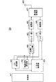
- FIG. 4 is a block diagram showing a configuration of the base station 203 shown in FIG. 2, which is a base station according to the present invention.
- the transmission process of the base station 203 shown in FIG. 4 will be described.
- the EPC communication unit 401 transmits and receives data between the base station 203 and the EPC (such as the MME unit 204) and the HeNBGW 205.
- the other base station communication unit 402 transmits / receives data to / from other base stations.
- the EPC communication unit 401 and the other base station communication unit 402 exchange information with the protocol processing unit 403, respectively. Control data from the protocol processing unit 403 and user data and control data from the EPC communication unit 401 and the other base station communication unit 402 are stored in the transmission data buffer unit 404.
- the data stored in the transmission data buffer unit 404 is passed to the encoder unit 405 and subjected to encoding processing such as error correction. There may exist data directly output from the transmission data buffer unit 404 to the modulation unit 406 without performing the encoding process.
- the encoded data is subjected to modulation processing by the modulation unit 406.
- the modulated data is converted into a baseband signal and then output to the frequency conversion unit 407 where it is converted into a radio transmission frequency. Thereafter, a transmission signal is transmitted from the antenna 408 to one or a plurality of mobile terminals 202.
- the reception processing of the base station 203 is executed as follows. Radio signals from one or more mobile terminals 202 are received by the antenna 408. The received signal is converted from a radio reception frequency to a baseband signal by the frequency conversion unit 407, and demodulated by the demodulation unit 409. The demodulated data is transferred to the decoder unit 410 and subjected to decoding processing such as error correction. Of the decoded data, control data is passed to the protocol processing unit 403 or EPC communication unit 401 and other base station communication unit 402, and user data is passed to the EPC communication unit 401 and other base station communication unit 402. A series of processing of the base station 203 is controlled by the control unit 411. Therefore, although not shown in FIG. 4, the control unit 411 is connected to the units 401 to 410.
- FIG. 5 is a block diagram showing the configuration of the MME according to the present invention.
- FIG. 5 shows the configuration of the MME 204a included in the MME unit 204 shown in FIG.
- the PDN GW communication unit 501 transmits and receives data between the MME 204a and the PDN GW.
- the base station communication unit 502 performs data transmission / reception between the MME 204a and the base station 203 using the S1 interface.
- the data received from the PDN GW is user data
- the user data is passed from the PDN GW communication unit 501 to the base station communication unit 502 via the user plane communication unit 503 and to one or more base stations 203.
- Sent When the data received from the base station 203 is user data, the user data is passed from the base station communication unit 502 to the PDN GW communication unit 501 via the user plane communication unit 503 and transmitted to the PDN GW.
- control data is passed from the PDN GW communication unit 501 to the control plane control unit 505.
- control data is transferred from the base station communication unit 502 to the control plane control unit 505.
- the HeNBGW communication unit 504 is provided when the HeNBGW 205 exists, and performs data transmission / reception through an interface (IF) between the MME 204a and the HeNBGW 205 depending on the information type.
- the control data received from the HeNBGW communication unit 504 is passed from the HeNBGW communication unit 504 to the control plane control unit 505.
- the processing result in the control plane control unit 505 is transmitted to the PDN GW via the PDN GW communication unit 501.
- the result processed by the control plane control unit 505 is transmitted to one or more base stations 203 via the S1 interface via the base station communication unit 502, and to one or more HeNBGWs 205 via the HeNBGW communication unit 504. Sent.
- the control plane control unit 505 includes a NAS security unit 505-1, an SAE bearer control unit 505-2, an idle state mobility management unit 505-3, and the like, and performs overall processing for the control plane.
- the NAS security unit 505-1 performs security of a NAS (Non-Access Stratum) message.
- the SAE bearer control unit 505-2 performs management of SAE (System Architecture) Evolution bearers and the like.
- the idle state mobility management unit 505-3 performs mobility management in a standby state (idle state; also referred to as LTE-IDLE state or simply idle), generation and control of a paging signal in the standby state,
- the tracking area of one or a plurality of mobile terminals 202 is added, deleted, updated, searched, and tracking area list is managed.
- the MME 204a distributes the paging signal to one or a plurality of base stations 203. Further, the MME 204a performs mobility control (Mobility control) in a standby state (Idle State). The MME 204a manages a tracking area list when the mobile terminal is in a standby state and in an active state (Active State). The MME 204a starts a paging protocol by transmitting a paging message to a cell belonging to a tracking area (tracking area: TrackingTrackArea) where the UE is registered. Management of the CSG of the Home-eNB 206 connected to the MME 204a, management of the CSG ID, and management of the white list may be performed by the idle state mobility management unit 505-3.
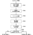
- FIG. 6 is a flowchart illustrating an outline from a cell search to a standby operation performed by a communication terminal (UE) in an LTE communication system.
- the communication terminal uses the first synchronization signal (P-SS) and the second synchronization signal (S-SS) transmitted from the neighboring base stations in step ST601, and performs slot timing, frame Synchronize timing.
- P-SS first synchronization signal
- S-SS second synchronization signal
- the P-SS and S-SS are collectively referred to as a synchronization signal (SS).
- SS synchronization signal
- a synchronization code corresponding to one-to-one is assigned to the PCI assigned to each cell.
- 504 patterns are under consideration. Synchronization is performed using the 504 PCIs, and the PCI of the synchronized cell is detected (specified).
- a cell-specific reference signal that is a reference signal (reference signal: RS) transmitted from the base station to each cell is detected for the synchronized cell.
- Measure the received power of RS Reference Signal Received Power: RSRP.
- RS Reference Signal Received Power
- RS Reference Signal
- a code corresponding to PCI one to one is used. By correlating with that code, it can be separated from other cells.
- deriving the RS code of the cell from the PCI specified in step ST601 it is possible to detect the RS and measure the received power of the RS.
- a cell having the best RS reception quality for example, a cell having the highest RS reception power, that is, the best cell is selected from one or more cells detected in step ST602.
- step ST604 the PBCH of the best cell is received and the BCCH that is broadcast information is obtained.
- MIB Master Information Block
- the MIB information includes, for example, DL (downlink) system bandwidth (also called transmission bandwidth setting (transmission bandwidth configuration: dl-bandwidth)), the number of transmission antennas, SFN (System frame number), and the like.
- SIB1 includes information related to access to the cell, information related to cell selection, and scheduling information of other SIBs (SIBk; an integer of k ⁇ 2).
- SIB1 includes a tracking area code (TrackingTrackArea Code: TAC).
- the communication terminal compares the TAC of SIB1 received in step ST605 with the TAC portion of the tracking area identifier (Tracking Area Identity: TAI) in the tracking area list already held by the communication terminal.
- the tracking area list is also referred to as a TAI list (TAI list).
- TAI is identification information for identifying a tracking area, and is composed of MCC (Mobile Country Code), MNC (Mobile Network Code), and TAC (Tracking Area Code).
- MCC Mobile Country Code
- MNC Mobile Network Code
- TAC Track Area Code
- MCC Mobile Country Code
- MNC Mobile Network Code
- TAC Track Area Code
- step ST606 If, as a result of the comparison in step ST606, the TAC received in step ST605 is the same as the TAC included in the tracking area list, the communication terminal enters a standby operation in the cell. In comparison, if the TAC received in step ST605 is not included in the tracking area list, the communication terminal passes through the cell to a core network (Core Network, EPC) including MME and the like, and TAU (Tracking Area Update). Request tracking area change to do
- EPC Core Network, EPC
- MME Mobile Management Entity
- TAU Track Area Update
- a device that constitutes a core network performs tracking based on the identification number (UE-ID, etc.) of the communication terminal sent from the communication terminal together with the TAU request signal. Update the area list.
- the core network side device transmits the updated tracking area list to the communication terminal.
- the communication terminal rewrites (updates) the TAC list held by the communication terminal based on the received tracking area list. Thereafter, the communication terminal enters a standby operation in the cell.
- a cell configured by an eNB has a relatively wide range of coverage.
- a cell is configured to cover a certain area with a relatively wide range of coverage of a plurality of cells configured by a plurality of eNBs.
- the cell configured by the eNB has a coverage that is narrower than the coverage of the cell configured by the conventional eNB. Therefore, in the same way as in the past, in order to cover a certain area, a larger number of eNBs having a smaller cell size are required as compared with the conventional eNB.
- a cell having a relatively large coverage such as a cell configured by a conventional eNB
- a macro cell an eNB that configures the macro cell
- a cell having a relatively small coverage such as a small cell
- an eNB configuring the small cell is referred to as a “small eNB”.
- the macro eNB may be a “wide area base station” described in Non-Patent Document 7, for example.
- the small eNB may be, for example, a low power node, a local area node, a hot spot, or the like.
- the small eNB is a pico eNB that constitutes a pico cell, a femto eNB that constitutes a femto cell, a HeNB, an RRH (Remote Radio Unit), an RRU (Remote Radio Unit), an RRE (Remote Radio Equipment), or an RN (Relay Node). There may be.
- the small eNB may be a “local area base station (Local (Base Station)” or “Home base station (Home Base Station)” described in Non-Patent Document 7.
- FIG. 7 is a diagram illustrating a concept of a cell configuration when a macro eNB and a small eNB coexist.
- a macro cell configured by a macro eNB has a relatively wide range of coverage 701.
- a small cell configured by a small eNB has a coverage 702 having a smaller range than a coverage 701 of a macro eNB (macro cell).
- the coverage of a cell configured by a certain eNB may be included in the coverage of a cell configured by another eNB.
- the small cell coverage 702 configured by the small eNB is included in the macro cell coverage 701 configured by the macro eNB. May be.
- a plurality of, for example, two small cell coverages 702 may be included in one macro cell coverage 701.
- a mobile terminal (UE) 703 is included in, for example, a small cell coverage 702 and performs communication via the small cell.
- the macro cell coverage 701 configured by the macro eNB and the small cell coverage 702 configured by the small eNB overlap in a complicated manner. Cases arise.
- a plurality of small cell coverages 702 configured by a plurality of small eNBs are configured in one macro cell coverage 701 configured by one macro eNB. Sometimes it happens.
- the 5th generation (5G) which is a future wireless access system aiming for commercialization from 2018 to 2020, includes LTE base stations compatible with LTE-A systems and 5G base stations compatible with 5G systems.
- the architecture to be deployed is considered.
- MeNB MasterNBeNB
- SeNB Secondary eNB
- C-plane control plane
- U-plane user plane
- FIG. 8 is a diagram showing a configuration of a conventional communication system 10.
- a first base station 11 that is a MeNB (hereinafter may be referred to as “BS # 1”) is connected to the core network 15 via an S1 interface, and a second base station 12 that is a SeNB (hereinafter referred to as “BS # 2” via an Xn interface). ”).
- BS # 3 A third base station 13 (hereinafter sometimes referred to as “BS # 3”) installed independently of other base stations is connected to the core network 15 via an S1 interface.
- 5G in addition to LTE-A, a plurality of base stations using different frequencies are connected. In addition, the amount of data in each base station is large.
- MeNB 11 is LTE-A
- LTE-A can cover a relatively wide cell radius.
- the frequency used is low, and there are many base stations already installed for existing base stations. This is because it can be covered.
- a 5G wireless base station is assigned.
- a base station having a low SHF (Super High Frequency) having a frequency of 6 GHz or less hereinafter sometimes referred to as a “low SHF base station”
- a base station having a high SHF having a frequency to be used exceeding 6 GHz (Hereinafter, sometimes referred to as “high SHF base station”) is likely to be placed at the same time.
- SeNB 12 for example, a low SHF base station
- Another base station such as a high SHF base station, can only be deployed as a stand alone base station 13 independent of other base stations. That is, the structure which connects several SeNB12 with respect to one MeNB11 cannot be taken.
- the mobile terminal (hereinafter may be referred to as “UE”) 14 can communicate with three or more base stations simultaneously, the communication path of the control plane (C-plane) information Control that cannot be aggregated into one and a mismatch between a plurality of control plane (C-plane) information does not occur on the UE 14 side is required.
- C-plane control plane
- control plane C-plane information is concentrated on one MeNB 11, and the processing capability of the MeNB 11 may become a network bottleneck.
- one base station corresponding to the MeNB is configured to be able to execute control plane (C-plane) data processing of a plurality of base stations connected as SeNBs.
- control plane C-plane
- U-plane user plane
- control plane (C-plane) data related to communication control among the information related to communication with the UE given from the core network is transmitted to the UE via one base station corresponding to the MeNB. Sent and received.
- control plane (C-plane) data of a communication terminal that can communicate simultaneously with a plurality of base stations.
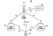
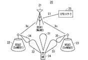
- FIG. 9 is a diagram showing a configuration of the communication system 20 according to Embodiment 1 of the present invention.
- the communication system 20 includes a first base station 21 (hereinafter sometimes referred to as “BS # 1”), a second base station 22 (hereinafter sometimes referred to as “BS # 2”), and a third base station 23 (hereinafter referred to as “BS # 1”). # 3 ”), and a mobile terminal (UE) 24.
- BS # 1 is installed as a MeNB.
- BS # 2 is installed as a first SeNB (hereinafter also referred to as “SeNB # 1”).
- BS # 3 is installed as a second SeNB (hereinafter sometimes referred to as “SeNB # 2”).
- MeNB corresponds to a master base station apparatus.
- the master base station apparatus performs main processing.
- the main process is, for example, an aggregation process in dual connectivity (DC).
- the first SeNB and the second SeNB correspond to secondary base station devices.
- the first SeNB and the second SeNB are each connected to the MeNB.
- One UE 24 is simultaneously communicating with three base stations 21 to 23, that is, BS # 1, BS # 2, and BS # 3.
- BS # 1 is an LTE-A base station
- BS # 2 is a 5G base station
- BS # 3 is a 5G base station.
- an interface capable of direct communication here, an Xn interface is provided.
- UE 24 communicates with BS # 1 for control plane (C-plane) data. Further, the UE 24 communicates user plane (U-plane) data with the BS # 1, BS # 2, and BS # 3, respectively.
- C-plane control plane
- U-plane user plane
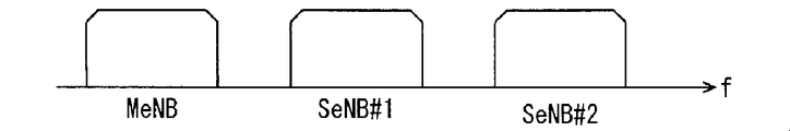
- FIG. 10 is a diagram illustrating an example of the frequency of the transmission / reception wave used in the communication system 20 according to the first embodiment of the present invention.
- the horizontal axis represents the frequency f.
- a first base station 21 installed as a MeNB, a second base station 22 installed as a SeNB # 1, and a third base station installed as a SeNB # 2 23 use transmission / reception waves of different frequency bands.
- FIG. 11 is a diagram illustrating an example of transmission / reception waveforms used in the communication system 20 according to the first embodiment of the present invention.
- FIG. 12 is a diagram illustrating an example of the frequency of the transmission / reception wave used in the example illustrated in FIG. 11.
- 11 and 12 show a case where each base station 21 to 22 and UE 24 apply an array antenna to a transmission / reception antenna.
- transmission / reception waveforms 31 to 35 having a beam shape having directivity are used. Thereby, space separability can be improved.
- a plurality of base stations can be simultaneously allocated in the same frequency band.
- the MeNB and the two SeNBs use transmission / reception waves of different frequency bands, but the SeNB # 1 and the SeNB # 2 use transmission / reception waves of the same frequency band.
- FIG. 13 is a diagram illustrating an example of a data flow in the communication system 20 according to the first embodiment of the present invention.
- the user plane (U-plane) data includes, for example, each base station, that is, the first base station 21 (hereinafter sometimes referred to as “BS # 1”), the second base station (hereinafter referred to as “BS”). # 2 ”) and the third base station (hereinafter also referred to as“ BS # 3 ”) and the core network device 25, which is a higher-level device (Next Generation Core Network), Transmission / reception is performed by communication between each base station and the UE 24.
- BS # 1 the first base station 21
- BS # 2 the second base station
- BS # 3 the third base station
- the core network device 25 which is a higher-level device (Next Generation Core Network)
- Transmission / reception is performed by communication between each base station and the UE 24.
- the user plane (U-plane) data is not limited to this, and is transmitted / received by communication between one base station, for example, BS # 1, and the core network device 25, which is a higher-level device, and BS # 1 and UE24. And communication between BS # 1 and UE 24 via BS # 2 or BS # 3.
- control plane (C-plane) data is transmitted / received only by communication between BS # 1 and UE24.
- the communication between BS # 1 and UE24 may be direct communication between BS # 1 and UE24, or may be via another base station, for example, BS # 3 or BS # 4.
- FIG. 14 is a diagram illustrating an example of a data flow in the communication system 20A, which is another example of the communication system according to the first embodiment of the present invention. Since the communication system 20A shown in FIG. 14 includes the same configuration as the communication system 20 shown in FIG. 13, the same reference numerals are given to the same configurations, and common descriptions are omitted.
- control plane (C-plane) data is transmitted / received by communication between the core network device 25 corresponding to the MME and the BS # 1.
- Control plane (C-plane) data may be transmitted and received by communication between BS # 1 and UE24.
- control plane (C-plane) data is communicated with UE24 via radio resources of BS # 2 and BS # 3 as shown in FIG. May be sent and received.
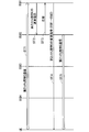
- FIG. 15 is a diagram illustrating an example of a sequence related to processing until communication is started in the communication system according to Embodiment 1 of the present invention.
- FIG. 15 shows a sequence in which BS # 1 and UE add BS # 2 and BS # 3 from the connected state.
- step ST11 BS # 1, BS # 2, BS # 3 and the UE are in a connected state.
- step ST12 BS # 1 notifies BS # 2 of the resource allocation request.
- step ST13 BS # 2 notifies the request response to BS # 1.
- step ST14 BS # 1 notifies the UE of a request to add BS # 2.
- Step ST15 the UE notifies the BS # 1 of an addition request response.
- the UE measures the synchronization signal of the designated BS # 2.
- step ST16 the UE synchronizes with the downlink (DL) of BS # 2.
- step ST17 BS # 2 notifies the UE of channel control, for example, PDCCH.
- step ST18 the UE starts conduction of user plane (U-plane) data based on the resource allocation state of the downlink signal specified by the PDCCH.
- U-plane user plane
- step ST19 BS # 1 notifies the resource allocation request to BS # 3.
- step ST20 BS # 3 notifies the request response to BS # 1.
- step ST21 BS # 1 notifies the UE of a request to add BS # 3.
- Step ST22 the UE notifies the BS # 1 of an addition request response.
- the UE measures the synchronization signal of the designated BS # 3.
- step ST23 the UE synchronizes with the downlink (DL) of BS # 3.
- Step ST24 BS # 3 notifies the UE of channel control, for example, PDCCH.
- step ST25 the UE starts to conduct user plane (U-plane) data based on the resource allocation state of the downlink signal specified by the PDCCH.
- U-plane user plane
- an instruction to delete BS # 1 is transmitted to the UE and executed.
- UEs and base stations compatible with the 5G standard may apply an array antenna to the transmitting / receiving antenna.
- space separation can be improved by using a beam-shaped transmission / reception waveform having directivity. Therefore, there is a possibility that a plurality of base stations may be assigned simultaneously in the same frequency band as shown in FIG.
- selection information for example, a beam ID
- a beam ID is added to the addition request signal of BS # 2 in step ST14 of FIG. 15 and the addition request signal of BS # 3 in step ST21.
- the beam for receiving the PDCCH can be selected, and it is not necessary to transmit the PDCCH information to all the beams, and channel resources can be used efficiently.
- beam selection information can be added to the PDCCH.
- BS # 1 since it is not necessary to consider BS # 1 regarding beam control, when a plurality of base stations are connected to BS # 1, the resource allocation processing of BS # 1 is reduced, and the processing load as a system is reduced. Even if the BS # 1 is an apparatus with limited processing capability such as an existing LTE-A base station, there is a possibility that it can be processed without causing a bottleneck.
- control plane (C-plane) data among the information related to communication with the UE given from the core network is transmitted / received to / from the UE via the MeNB.
- the process of control plane (C-plane) data when the UE communicates with a plurality of base stations can be simplified.
- control plane (C-plane) data is given to the MeNB by the core network.
- Control plane (C-plane) data given from the core network is given to the UE by the MeNB and also given to the UE via a plurality of SeNBs.
- Embodiment 1 Modification 1 As a first modification of the first embodiment, there is a configuration in which a part of the processing of control plane (C-plane) data is distributed to base stations other than the MeNB, for example, BS # 2 described later.
- FIG. 16 is a diagram showing a configuration of the communication system 40 in the first modification of the first embodiment of the present invention.
- the communication system 40 includes a first base station 41 (hereinafter also referred to as “BS # 1”), a second base station 42 (hereinafter also referred to as “BS # 2”), and a third base station 43 (hereinafter referred to as “BS # 1”). # 3 ”), a fourth base station 44 (hereinafter also referred to as“ BS # 4 ”), a mobile terminal (UE) 45, and a core network 46.
- BS # 1 first base station 41
- BS # 2 a second base station 42
- BS # 1 third base station 43
- # 3 a fourth base station 44
- UE mobile terminal
- BS # 1 is a base station for LTE-A
- BS # 2 is a base station for LTE-A
- BS # 3 is a base station for LTE-A
- BS # 4 is 5G base stations.
- the RRC messages for the 5G standard are characterized by being collectively transmitted / received by BS # 2.
- BS # 1 and BS # 2 are connected by an inter-base station interface, specifically, an Xn interface.
- BS # 2 and BS # 3, and BS # 2 and BS # 4 are connected by an inter-base station interface, specifically, an Xn interface.
- BS # 1 and core network 46 are connected by an S1 interface.
- BS # 1 handles the RRC message for BS # 1 and control plane (C-plane) information for adding BS # 2.
- C-plane control plane
- BS # 2 handles control plane (C-plane) information for BS # 2, BS # 3 and BS # 4.
- UE45 transmits / receives control plane (C-plane) information with BS # 1 and BS # 2.
- FIG. 17 is a diagram illustrating an example of a data flow in the communication system 40 according to the first modification of the first embodiment of the present invention.
- FIG. 17 shows an example of arrangement of RRC processing functions.
- BS # 1 is, for example, a first radio system of LTE-A (hereinafter also referred to as “first system”).
- BS # 2, BS # 3, and BS # 4 are, for example, a 5G second wireless system (hereinafter also referred to as “second system”).
- BS # 1 has a function of RRC processing for the first system.
- BS # 2 has a function of RRC processing for the second system.
- the RRC message for the first system may be transmitted / received between the BS # 1 and the UE, or may be communicated with the UE via the radio resource of the BS # 2.
- BS # 2 has a function of the RRC process for the second system.
- the RRC message for the second system may be transmitted / received between BS # 2 and the UE, or may be communicated with the UE via the radio resources of BS # 3 and BS # 4.
- the control plane (C-plane) information for the second system is transmitted / received by communication between the core network 46 and BS # 2.
- the communication between the core network 46 and BS # 2 may be direct communication between the core network 46 and BS # 2, or may be communication via BS # 1.
- UE connectivity refers to the ease of connection of a UE with a base station.
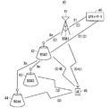
- FIG. 18 is a diagram showing an example of cell arrangement in the communication system 40 according to the first modification of the first embodiment of the present invention.
- BS # 1 constitutes a macro cell 51 having a cell radius of 500 m
- BS # 2 constitutes a microcell 52 having a cell radius of 200 m
- BS # 3 and BS # For example, when 4 configures the small cells 53 and 54 having a cell radius of 50 m, the connection between the BS # 1 and the UE can be maintained in a wide range.
- BS # 2 which is another second base station 42A exists in the cell 51 of BS # 1.
- BS # 2 constitutes a microcell 52A having a cell radius of 200 m, for example, like BS # 2.
- BS # 5 constitutes a small cell 55 having a cell radius of 50 m, for example, like BS # 3 and BS # 4.
- the BS # 2 processes the control plane (C-plane) data of the BS # 2 and controls the base stations BS # 3 and BS # 4 that are subordinate to the cell 52 of the BS # 2.
- Plane (C-plane) data processing is executed. Thereby, the processing load of BS # 1 can be reduced.
- the control plane (C-plane) data processing of BS # 2 ′ and the control plane (C-plane) of BS # 5, which is a base station under the cell 52A of BS # 2 ′ are processed. It is preferable to execute data processing. As a result, the processing load of BS # 1 can be further reduced.
- FIG. 19 is a diagram illustrating an example of a sequence related to processing until communication is started in the communication system 40 according to the first modification of the first embodiment of the present invention.
- FIG. 19 shows a sequence example for establishing connections with a plurality of base stations.
- FIG. 19 shows a sequence in which BS # 1 and UE add BS # 2, BS # 3, and BS # 4 from the connected state.
- step ST31 BS # 1 and UE are in a connected state.
- step ST32 BS # 1 notifies the resource allocation request to BS # 2.
- step ST33 BS # 2 notifies BS # 1 of the request response.
- step ST34 BS # 1 notifies the UE of a request to add BS # 2.
- step ST35 the UE notifies the addition request response to BS # 1.
- the UE measures the synchronization signal of the designated BS # 2.
- step ST36 the UE synchronizes with the downlink (DL) of BS # 2.
- step ST37 BS # 2 notifies the UE of channel control, for example, PDCCH.
- step ST38 the UE starts conduction of user plane (U-plane) data based on the resource allocation state of the downlink signal specified by the PDCCH.
- U-plane user plane
- step ST39 BS # 2 notifies BS # 3 of the resource allocation request.
- step ST40 BS # 3 notifies the request response to BS # 2.
- step ST41 BS # 2 notifies the UE of an addition request for BS # 3.
- step ST42 the UE notifies the BS # 2 of an addition request response.
- the UE measures the synchronization signal of the designated BS # 3.
- step ST43 the UE synchronizes with the downlink (DL) of BS # 3.
- step ST44 BS # 3 notifies the UE of channel control, for example, PDCCH.
- step ST45 the UE starts conduction of user plane (U-plane) data based on the resource allocation state of the downlink signal specified by the PDCCH.
- U-plane user plane
- step T46 BS # 2 notifies BS # 4 of the resource allocation request.
- step ST47 BS # 4 notifies BS # 2 of the request response.
- step ST48 BS # 2 notifies the UE of a request to add BS # 4.
- Step ST49 the UE notifies the BS # 2 of an addition request response.
- the UE measures the synchronization signal of the designated BS # 3.
- step ST50 the UE synchronizes with the downlink (DL) of BS # 4.
- step ST51 BS # 4 notifies the UE of channel control, for example, PDCCH.
- Step ST52 the UE starts to conduct user plane (U-plane) data based on the resource allocation state of the downlink signal specified by the PDCCH.
- U-plane user plane
- the BS # 2 is deleted by an instruction from the BS # 1 to the UE, similarly to the addition of the base station.
- BS # 3 and BS # 4 are deleted by an instruction from BS # 2.
- BS # 2 When BS # 2 is deleted while BS # 3 and BS # 4 are connected, a sequence for deleting BS # 2 from BS # 2 after an instruction to delete the base stations of BS # 3 and BS # 4 It is good.
- BS # 3 and BS # 4 may be deleted at the same time by an instruction to delete BS # 2 from BS # 1.
- the BS # 2 When adding the above-described BS # 2, the BS # 2 includes a message for enabling the RRC processing function of the second system in the BS # 2 addition request instruction for notifying the UE. In addition, a message for validating the RRC processing function is included in the resource allocation request instruction from BS # 1 to BS # 2. If it is invalid, BS # 2 does not validate the RRC processing function of the second system, and has the same role as BS # 2 of the first embodiment shown in FIG.
- the sequence shown in FIG. 19 is executed. Specifically, the radio resource control (RRC) process for BS # 2, BS # 3, and BS # 4, which are SeNBs, is performed as shown in FIG. 19, among BS # 2, BS # 3, and BS # 4. One, for example, by BS # 2. As a result, it is possible to reduce the processing load of the control plane (C-plane) data of BS # 1. Therefore, it is possible to shorten the time for sequence processing such as base station addition processing, and therefore it is possible to suppress processing delay.
- RRC radio resource control
- Embodiment 1 Modification 2 As a second modification of the first embodiment, in the configuration of the first modification of the first embodiment shown in FIG. 16, the RRC message is selected when there are a plurality of component carriers (Component Carrier: CC) in the BS # 2. The example which communicates by CC is shown. Since the configuration of the communication system of this modification is the same as that of the communication system 40 of Modification 1 of Embodiment 1 shown in FIG. 16, the illustration and common description of the configuration are omitted.
- Component Carrier Component Carrier
- 20 to 22 are diagrams showing an example of the frequency of transmission / reception waves used in the communication system according to the second modification of the first embodiment of the present invention.
- the horizontal axis indicates the frequency f.
- FIG. 20 the frequency of the transmission / reception wave used by BS # 1 is shown.
- FIG. 21 shows the frequency of the transmission / reception wave used in BS # 2.
- FIG. 22 the frequency of the transmission / reception wave used in BS # 3 and BS # 4 is shown.
- BS # 1 transmits / receives the first system RRC message using one type of transmission / reception wave.
- the bandwidth BW1 of the transmission / reception wave used in BS # 1 is, for example, 20 MHz.
- BS # 2 handles two CCs. Therefore, in this modification, the RRC message is transmitted by either CC # 1 or CC # 2. As a result, the UE can obtain necessary RRC information without performing modulation processing and demodulation processing on all CCs.
- the transmission / reception wave bandwidth BW2 used in BS # 2 shown in FIG. 21 is, for example, 100 MHz.
- the RRC message for the second system is transmitted / received using CC # 1 among the two CCs used in BS # 2.
- CC # 2 of BS # 2 to which no RRC is assigned is treated as equivalent to other BS # 3 and BS # 4. This can simplify the management of user plane (U-plane) resources.
- the transmission / reception wave bandwidth BW3 used in BS # 3 shown in FIG. 22 is, for example, 100 MHz.
- the RRC message for the second system is transmitted / received by BS # 3, it is mapped to one of CC # 0 to CC # 7 or a plurality of CCs.
- By handling RRC with only a part of the CC it is possible to simplify the management of user plane (U-plane) resources of the CC to which the RRC is not mapped.
- U-plane user plane
- Embodiment 1 Modification 3 As a third modification of the first embodiment, a method in which the configuration of the first embodiment and the configuration of the first modification of the first embodiment are combined will be described.
- the RRC processing function for the second system is executed by BS # 1.
- the RRC processing function for the second system is executed by BS # 2.
- FIG. 23 is a diagram showing an example of a sequence relating to processing for changing the RRC processing function for the second system from BS # 2 to BS # 1.
- Step ST61 RRC communication for the second system is performed between the BS # 2 and the UE.
- step ST62 BS # 1 notifies BS # 2 of a release instruction for RRC processing for the second system.
- step ST63 BS # 2 notifies BS # 1 of a response that can be handled.
- BS # 1 notifies the UE of a change instruction for the RRC process for the second system.
- the change instruction for the second system RRC process is an instruction for the second system RRC process to change from BS # 2 to BS # 1.
- Specific examples of instruction contents include a change in radio resources for handling the RRC message for the second system and a change in message format.
- Step ST65 RRC communication for the second system is performed between the BS # 1 and the UE.
- FIG. 24 is a diagram illustrating an example of a sequence relating to processing for changing the RRC processing function for the second system from BS # 1 to BS # 2.
- Step ST71 RRC communication for the second system is performed between the BS # 1 and the UE.
- step ST72 BS # 1 notifies BS # 2 of an instruction to add the second system RRC process.
- step ST73 BS # 2 notifies BS # 1 of a response that can be handled.
- BS # 1 notifies the UE of an instruction to change the RRC process for the second system.
- the instruction to change the RRC process for the second system is an instruction to change the RRC process for the second system from BS # 1 to BS # 2.
- Specific examples of instruction contents include a change in radio resources for handling the RRC message for the second system and a change in message format.
- Step ST75 RRC communication for the second system is performed between BS # 2 and the UE.
- the RRC process is performed in accordance with the communication state of the UE and the corresponding function of the UE, the load state of the base station, the number of connected terminals, and so Can be distributed.
- the RRC processing for the first system and the RRC processing for the second system are performed in one place.
- it is also effective to transmit and receive RRC messages from BS # 1.
- Embodiment 2 the concept of beam control may be added.
- the interval between the base stations is reduced. This may increase the number of base stations in one cell.
- various types of base stations may be mixed and arranged. For example, a base station of URLLC (Ultra-Reliability and Low Latency Communication) or a plurality of base stations with different frequencies may be mixed and arranged. When this happens, information about the base station to be notified increases. When this is transmitted by one macro base station, there is a problem that processing of the macro base station becomes large.
- URLLC Ultra-Reliability and Low Latency Communication
- the broadcast information is divided into basic information and additional information.
- the basic information is transmitted from BS # 1 having a large cell radius, and the additional information is installed in the cell of BS # 1, and the cell radius is smaller than BS # 1 or equivalent to BS # 1. 2 to transmit from.
- FIG. 25 is a diagram showing a configuration of the communication system 60 according to Embodiment 2 of the present invention.
- the communication system 60 includes a first base station 61 (hereinafter also referred to as “BS # 1”), a second base station 62 (hereinafter also referred to as “BS # 2”), and a third base station 63 (hereinafter referred to as “BS # 1”). # 3 ”), a fourth base station 64 (hereinafter also referred to as“ BS # 4 ”), and a mobile terminal (UE) 65.
- BS # 1 first base station 61
- BS # 2 second base station 62
- BS # 1 third base station 63
- # 3 a fourth base station 64
- UE mobile terminal
- BS # 1 constitutes a macro cell 71 having a cell radius of 500 m, for example.
- BS # 2 constitutes a microcell 72 having a cell radius of 200 m, for example.
- BS # 3 and BS # 4 constitute small cells 73 and 74 having a cell radius of 50 m, for example.
- each base station 61 to 64 is installed as a stand-alone base station independently of other base stations, the broadcast information BrI # 1 to BrI is transmitted from each base station 61 to 64. # 3 is transmitted.
- the description of the broadcast information transmitted from the fourth base station 64 is omitted in order to prevent the drawing from becoming complicated and difficult to understand. Also broadcast information is transmitted.
- At least a part of the broadcast information for each SeNB is one of a plurality of SeNBs, Specifically, the UE is notified by BS # 2.
- This configuration eliminates the need for BS # 1 to transmit broadcast information for all base stations under the cell, and reduces the data amount of broadcast information BrI # 1 of BS # 1. As a result, it is possible to reduce the proportion of the broadcast information BrI # 1 occupying the radio resources of BS # 1. Further, by shortening the transmission period of the broadcast information BrI # 1 of BS # 1, it is possible to shorten the time required for the initial connection of the UE to BS # 1.
- the broadcast information for each SeNB may be notified directly from the BS # 2 to the UE as shown in FIG. 26 to be described later, or other base stations from the BS # 2 as shown in FIGS. 27 and 28 to be described later.
- the UE may be notified via.
- Information necessary for the initial connection of BS # 2 includes, for example, SIB1 (Cell access and cell reselection related information, scheduling information info), SIB2 (radio resource configuration, that is is common, for common) used in LTE-A all UEs).
- SIB1 Cell access and cell reselection related information
- SIB2 radio resource configuration, that is is common, for common
- the additional information corresponds to broadcast information other than information necessary for the initial connection of the BS # 2.
- FIG. 26 is a diagram illustrating an example of a sequence related to a process of acquiring broadcast information in the communication system 60 according to the second embodiment of the present invention.
- FIG. 26 shows an example of a sequence related to a process in which the UE acquires broadcast information for BS # 1, BS # 2, BS # 3, and BS # 4.
- step ST81 BS # 1 notifies the UE of the broadcast information for BS # 1.
- the UE reads the control information for BS # 1 from the broadcast information notified from BS # 1.
- step ST82 communication is performed between BS # 1 and the UE.
- step ST83 BS # 1 notifies the basic information of the broadcast information for BS # 2 to the UE.
- the UE needs to connect to BS # 2, the UE reads basic information of the broadcast information for BS # 2 among the broadcast information of BS # 1, and obtains information for accessing BS # 2.
- step ST84 BS # 2 notifies the UE of the additional information of the broadcast information for BS # 2.
- the UE reads the additional information of BS # 2 from the broadcast information of BS # 2.
- step ST85 communication is performed between BS # 2 and the UE.
- step ST86 BS # 2 notifies the UE of the broadcast information for BS # 3 and the broadcast information for BS # 4.
- the control information for BS # 3 or the control information for BS # 4 is read from the broadcast information notified from BS # 2.
- step ST87 communication is performed between BS # 3 and the UE.
- step ST88 communication is performed between BS # 4 and the UE.
- FIG. 27 is a diagram illustrating an example of a sequence related to a process of notifying broadcast information based on a UE request.
- FIG. 27 shows an example in which BS # 2 corresponds to the broadcast information request from the UE.
- step ST91 BS # 1 notifies BS # 1 broadcast information to the UE.
- step ST92 communication is performed between BS # 1 and the UE.
- step ST93 BS # 1 notifies the basic information of the broadcast information for BS # 2 to the UE.
- step ST94 BS # 2 notifies the UE of the additional information of the broadcast information for BS # 2.
- step ST95 communication is performed between BS # 2 and the UE.
- step ST96 the UE notifies BS # 2 of a broadcast information request for BS # 3.
- step ST97 BS # 2 notifies the UE of radio resource allocation information for notifying broadcast information.
- step ST98 BS # 2 notifies the UE of broadcast information for BS # 3 using the corresponding radio resource.
- step ST99 communication is performed between BS # 3 and the UE.
- FIG. 28 is a diagram illustrating another example of a sequence related to a process of notifying broadcast information based on a UE request.
- FIG. 28 shows a method of notifying the broadcast information requested from the UE using the radio resource of another base station, not the base station that received the request.
- step ST101 BS # 1 and UE are in a communication state.
- step ST102 BS # 2 and UE are in a communication state.
- step ST103 BS # 3 and the UE are in a communication state.
- step ST104 the UE notifies the BS # 2 of a broadcast information request for BS # 4.
- step ST105 BS # 2 notifies BS # 3 of a broadcast information notification resource securing request. Specifically, BS # 2 notifies broadcast information using the radio resource of BS # 3. BS # 2 instructs BS # 3 about the size of the broadcast information and the used radio resource information.
- step ST106 when the radio resource can be secured, BS # 3 notifies the secured radio information to BS # 2.
- Step ST107 BS # 2 notifies the UE of allocation information of the corresponding broadcast information.
- step ST108 BS # 3 notifies the UE of broadcast information for BS # 4.
- a configuration is also considered in which a beam is formed with a transmission / reception antenna waveform to increase the directivity of the antenna.
- spatial multiplexing becomes possible.
- the base station that receives the broadcast information request from the UE and the base station that transmits the broadcast information request from the UE can be freely selected. As a result, the radio resources can be effectively used.
- transmitting the same broadcast information from a plurality of base stations is also an effective configuration for improving data reliability.
- radio resources for transmitting broadcast information in units of CC (Component Carrier), as in Modification 2 of Embodiment 1.
- CC Component Carrier
- Embodiment 3 Regarding the processing of user plane (U-plane) data, in a dual connectivity split bearer configuration up to LTE-A, PDCP (Packet Data Convergence Protocol) function is arranged in MeNB (Master eNB), and SeNB (Secondary The configuration in which eNB) processes lower layers than RLC is standardized.
- PDCP Packet Data Convergence Protocol
- MeNB Master eNB
- SeNB Secondary The configuration in which eNB) processes lower layers than RLC is standardized.
- a user plane (U-plane) data processing method for Embodiment 1 data divided from the PDCP of BS # 1 is used as BS # 2 and BS # 3. Process in layers below RLC.
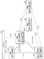
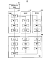
- FIG. 29 is a block diagram showing a configuration of the communication system 80 according to the third embodiment of the present invention.
- the communication system 80 includes a first base station 81 (hereinafter also referred to as “BS # 1”), a second base station 82 (hereinafter also referred to as “BS # 2”), and a third base station 83 (hereinafter referred to as “BS # 1”). # 3 ”) and UE 84 and host device 85.
- BS # 1 includes a PDCP processing unit, an RLC processing unit, a MAC processing unit, and a PHY processing unit.
- BS # 2 and BS # 3 include an RLC processing unit, a MAC processing unit, and a PHY processing unit.
- the UE84 corresponds to BS # 1, PDCP processing unit corresponding to BS # 1, RLC processing unit, MAC processing unit and PHY processing unit, RLC processing unit corresponding to BS # 2, MAC processing unit and PHY processing unit, and BS # 3 An RLC processing unit, a MAC processing unit, and a PHY processing unit.
- the higher level device 85 includes a core network device and a serving gateway (abbreviation: SGW).
- BS # 1 and BS # 2 are equivalent to the configuration (split bearer) of option 3C of dual connectivity.
- BS # 1 receives user plane (U-plane) data from the host device 85.
- ROHC Robot Header ⁇ Compression
- encryption processing are performed by PDCP processing by the PDCP processing unit of BS # 1.
- PDCP SN Sequence Number
- the data is divided and transmitted to the RLC processing unit of BS # 1, the RLC processing unit of BS # 2, and the RLC processing unit of BS # 3.
- the MAC process, and the PHY process are executed in each base station, it is transmitted to the UE 84.
- the UE 84 performs PHY processing, MAC processing, and RLC processing corresponding to each base station, and then aggregates them into one PDCP.
- the reverse procedure described above is performed for uplink data.
- FIG. 30 is a block diagram showing a configuration of a communication system 80A, which is another example of the communication system according to Embodiment 3 of the present invention. 30 includes the same configuration as that of the communication system 80 illustrated in FIG. 29, the same reference numerals are given to the same configurations, and common description is omitted.
- the communication system 80A includes a second base station 82A instead of the second base station 82 shown in FIG.
- the second base station 82A further includes a data division processing unit (also referred to as “SPLIT processing unit”) in addition to the configuration of the second base station 82 of FIG.
- SPLIT processing unit also referred to as “SPLIT processing unit”
- BS # 1 only needs to support a user plane (U-plane) interface that supports only connection with BS # 2, and does not change the specification of Option 3C of LTE dual connectivity. It becomes possible to do.
- U-plane user plane
- the user plane (U-plane) data among the information related to communication with the UE given from the core network is transmitted via one base station BS # 1 corresponding to the MeNB. Are transmitted to and received from the UE.
- user plane (U-plane) data is given to the MeNB by the core network, given to the UE by the MeNB, and given to the UE via a plurality of SeNBs.
- SeNBs SeNBs
- FIG. 31 is a block diagram showing a configuration of a communication system 90 which is still another example of the communication system according to Embodiment 3 of the present invention.
- the communication system 90 includes a first base station 91 (hereinafter also referred to as “BS # 1”), a second base station 92 (hereinafter also referred to as “BS # 2”), and a third base station 93 (hereinafter referred to as “BS # 1”). # 3 ”), a fourth base station 94 (hereinafter also referred to as“ BS # 4 ”), a UE 95, a first core network 96, and a second core network 97.
- the first core network 96 is a core network for LTE-A.
- the second core network 97 is a 5G core network.
- BS # 1 and BS # 2 include a PDCP processing unit, an RLC processing unit, a MAC processing unit, and a PHY processing unit.
- BS # 3 and BS # 4 include an RLC processing unit, a MAC processing unit, and a PHY processing unit.
- the UE 95 includes a PDCP processing unit, RLC processing unit, MAC processing unit and PHY processing unit corresponding to BS # 1, a PDCP processing unit, RLC processing unit, MAC processing unit and PHY processing unit corresponding to BS # 2, and BS RLC processing unit, MAC processing unit and PHY processing unit corresponding to # 3, and RLC processing unit, MAC processing unit and PHY processing unit corresponding to BS # 4.
- BS- # 1 of LTE-A is connected to an LTE core network (Core ⁇ ⁇ ⁇ ⁇ ⁇ Network).
- 5G BS # 2 is connected to the 5G core network.
- 5G BS # 3 and BS # 4 are configured to process user plane (U-plane) data divided from the PDCP processing unit of BS # 2. Indicates.
- BS # 1 is an LTE-A base station and BS # 2, BS # 3, and BS # 4 are 5G base stations.
- the PDCP processing function may be different for LTE-A and 5G.
- the amount of 5G user plane (U-plane) data is the same as the LTE user plane (U-plane). plane) may be several tens of times the amount of data, and the performance of the PDCP processing unit of the conventional LTE-A base station may become a bottleneck. In that case, the 5G PDCP process needs to be executed by the 5G base station.
- PDCP processing of user plane (U-plane) data of the 5G system is executed by BS # 2, and BS # 3 and BS # 4 under its control are executed.
- the user plane (U-plane) data is transmitted to the RLC processing unit.
- BS # 1 is connected to a first core network 96 which is a core network for LTE-A.
- BS # 1 processes the user plane (U-plane) data received from the first core network 96 in the PDCP processing unit, RLC processing unit, MAC processing unit, and PHY processing unit in BS # 1, and then transmits the data to UE95. Send.
- U-plane user plane
- BS # 2 is connected to a second core network 97, which is a 5G core network (Next Generation Core Core).
- BS # 2 executes processing such as PDCP ROHC, encryption, SN (Sequence Number) assignment, etc., on the user plane (U-plane) data received from the second core network 97 by the PDCP processing unit in BS # 2. To do.
- the data after the PDCP processing is divided and transmitted to the RLC processing unit in BS # 2, the RLC processing unit in BS # 3, and the RLC processing unit in BS # 4. After being processed by the RLC processing unit, MAC processing unit, and PHY processing unit of each base station, it is transmitted to the UE 95.
- the UE 95 executes PHY processing, MAC processing, and RLC processing corresponding to each base station, and then aggregates them into two, that is, PDCP for LTE-A and PDCP for 5G.
- This configuration can simplify the PDCP process regardless of the processing capability of the LTE-A base station. Even when the connection interface between BS # 1 and BS # 2 uses a network called “Non Ideal Network” that cannot guarantee the delay specification of data processing, 5G data can be transmitted and received without any problem. .
- the user plane (U-plane) data for the BS # 2, BS # 3, and BS # 4, which are SeNBs and the second system, are BS # 2, BS # 3, and BS # 3. It is transmitted / received to / from the UE via one of BS # 4, for example, BS # 2.
- the user plane (U-plane) data of the second system is given to the representative SeNB (BS # 2) by the core network, and given to the UE by the representative SeNB, and a plurality of the same system To the UE via the SeNB.
- U-plane user plane
- Embodiment 4 In the conventional dual connectivity configuration, the UE notifies the MeNB of the measurement result of each base station as a measurement report.
- the measurement report for BS # 1 is notified to BS # 1, and the measurement reports for BS # 2, BS # 3 and BS # 4 are sent to BS # 2. Notice.
- FIG. 32 is a diagram showing an exemplary sequence related to the measurement report processing of the communication system in the fourth embodiment of the present invention.
- step ST111 the UE notifies BS # 1 of measurement information regarding BS # 1 and BS # 2 as a measurement report (Measurement Report).
- BS # 1 notifies BS # 2 of a base station addition request (Addition) Request) in order to determine whether or not communication with the UE is possible based on the measurement information regarding BS # 2. Specifically, BS # 1 notifies BS # 2 of an addition request for BS # 2.
- step ST113 when the base station can be added, BS # 2 notifies BS # 1 of an addition request response (Addition Request Acknowledge) (hereinafter also referred to as “addition request Ack”) as a normal response.
- addition request Ack an addition request response
- BS # 1 notifies the UE of an RRC connection reconfiguration (RRC Connection Reconfiguration) message as a request for adding a base station. Specifically, BS # 1 notifies the UE of an addition request for BS # 2. Information instructing to notify BS # 2 of measurement reports of BS # 2 and BS # 3, 4 may be included in the RRC connection reconfiguration message in step ST114.
- RRC connection reconfiguration RRC Connection Reconfiguration
- Step ST115 the UE notifies the BS # 1 of an RRC connection reconfiguration complete (RRC ⁇ Connection Reconfiguration Complete) message as an addition completion notification after the establishment of communication with the BS # 2.
- RRC connection reconfiguration complete RRC ⁇ Connection Reconfiguration Complete
- Step ST116 after establishing communication with BS # 2, the UE notifies BS # 1 of measurement information regarding BS # 1 as a measurement report (Measurement Report) for BS # 1.
- step ST117 the UE notifies BS # 2 of measurement information regarding BS # 2, BS # 3, and BS # 4 as a measurement report (Measurement Report) for BS # 2.
- Step ST118 BS # 2 sends a base station addition request (Addition Request) to BS # 3 in order to determine whether or not communication between BS # 3 and the UE is possible based on measurement information regarding BS # 3. Notify Specifically, BS # 2 notifies BS # 3 of an addition request for BS # 3.
- a base station addition request (Addition Request)
- step ST119 BS # 3 notifies BS # 2 of an addition request Ack as a normal response when a base station can be added.
- BS # 2 notifies the UE of an RRC connection reconfiguration (RRC Connection Reconfiguration) message as a base station addition request. Specifically, BS # 2 notifies the UE of a request to add BS # 3.
- RRC connection reconfiguration RRC Connection Reconfiguration
- step ST121 the UE notifies the BS # 2 of an RRC connection reconfiguration complete (RRC Connection Reconfiguration Complete) message as an addition completion notice after the establishment of communication with the BS # 3.
- RRC connection reconfiguration complete RRC Connection Reconfiguration Complete
- step ST122 BS # 2 notifies the UE of measurement information regarding BS # 2, BS # 3, and BS # 4 as a measurement report (Measurement Report).
- step ST123 BS # 2 sends a base station addition request (Addition Request) to BS # 4 in order to determine whether or not communication between BS # 4 and the UE is possible based on measurement information regarding BS # 4. Notify Specifically, BS # 2 notifies BS # 3 of an addition request for BS # 4.
- a base station addition request (Addition Request)
- step ST124 when a base station can be added, BS # 4 notifies BS # 2 of an addition request Ack as a normal response.
- BS # 2 notifies the UE of an RRC connection reconfiguration (RRC Connection Reconfiguration) message as a base station addition request. Specifically, BS # 2 notifies the UE of an addition request for BS # 4.
- RRC connection reconfiguration RRC Connection Reconfiguration
- Step ST126 the UE notifies the BS # 2 of an RRC connection reconfiguration complete (RRC Connection Reconfiguration Complete) message as an addition completion notice after communication establishment with the BS # 4 is completed.
- RRC connection reconfiguration complete RRC Connection Reconfiguration Complete
- Step ST127 after establishing communication with BS # 4, the UE notifies BS # 1 of measurement information regarding BS # 1 as a measurement report (Measurement Report) for BS # 1.
- step ST1208 the UE notifies BS # 2 of measurement information regarding BS # 2, BS # 3, and BS # 4 as a measurement report (Measurement Report) for BS # 2.
- the base station that the UE reports the measurement report may be selected.
- the measurement reports (Measurement Report) for BS # 2, BS # 3, and BS # 4 may be notified using the radio resources of BS # 3 and BS # 4.
- the notification destination of the measurement report may be changed by the above-described RRC message, or may be returned before the change of the notification destination.
Abstract
La présente invention concerne un système de communication capable de simplifier le traitement de données de plan de commande et/ou de données de plan d'utilisateur lorsqu'un dispositif terminal de communication communique avec une pluralité de dispositifs de station de base. Dans un système de communication (20), une pluralité de stations de base (21-23) comprennent un MeNB, qui est une première station de base (21) (BS#1), et une pluralité de SeNB (SeNB#1, #2) connectées à la MeNB. Des données de plan de commande concernant une commande de communication et/ou des données de plan d'utilisateur concernant un utilisateur parmi des informations concernant une communication avec un équipement d'utilisateur (UE) (24) et fournies par un réseau fédérateur (25) sont transmises à l'UE (24) et reçues en provenance de ce dernier via la première station de base (21) qui est la MeNB.
Priority Applications (13)
| Application Number | Priority Date | Filing Date | Title |
|---|---|---|---|
| EP23199706.5A EP4277403A1 (fr) | 2016-08-05 | 2017-07-31 | Système de communication, station de base secondaire et appareil utilisateur |
| JP2018531874A JPWO2018025789A1 (ja) | 2016-08-05 | 2017-07-31 | 通信システム |
| CN201780047439.1A CN109565810A (zh) | 2016-08-05 | 2017-07-31 | 通信系统 |
| CN202310456549.0A CN116249213A (zh) | 2016-08-05 | 2017-07-31 | 通信系统、第1基站、第2基站及用户装置 |
| EP17836894.0A EP3496482A4 (fr) | 2016-08-05 | 2017-07-31 | Système de communication |
| CN202310458543.7A CN116249214A (zh) | 2016-08-05 | 2017-07-31 | 通信系统、辅基站及用户装置 |
| CN202310461770.5A CN116249215A (zh) | 2016-08-05 | 2017-07-31 | 通信系统、第1基站、第2基站及用户装置 |
| CN202310461763.5A CN116234037A (zh) | 2016-08-05 | 2017-07-31 | 通信系统、辅基站及用户装置 |
| US16/320,119 US10827462B2 (en) | 2016-08-05 | 2017-07-31 | Communication system |
| US17/030,045 US11343798B2 (en) | 2016-08-05 | 2020-09-23 | Communication system |
| JP2021190943A JP7241850B2 (ja) | 2016-08-05 | 2021-11-25 | 通信システムおよび通信端末装置 |
| US17/723,600 US20220248371A1 (en) | 2016-08-05 | 2022-04-19 | Communication system |
| US18/304,185 US20230300796A1 (en) | 2016-08-05 | 2023-04-20 | Communication system, secondary base station, and user apparatus |
Applications Claiming Priority (2)
| Application Number | Priority Date | Filing Date | Title |
|---|---|---|---|
| JP2016154272 | 2016-08-05 | ||
| JP2016-154272 | 2016-08-05 |
Related Child Applications (2)
| Application Number | Title | Priority Date | Filing Date |
|---|---|---|---|
| US16/320,119 A-371-Of-International US10827462B2 (en) | 2016-08-05 | 2017-07-31 | Communication system |
| US17/030,045 Continuation US11343798B2 (en) | 2016-08-05 | 2020-09-23 | Communication system |
Publications (1)
| Publication Number | Publication Date |
|---|---|
| WO2018025789A1 true WO2018025789A1 (fr) | 2018-02-08 |
Family
ID=61073692
Family Applications (1)
| Application Number | Title | Priority Date | Filing Date |
|---|---|---|---|
| PCT/JP2017/027597 WO2018025789A1 (fr) | 2016-08-05 | 2017-07-31 | Système de communication |
Country Status (5)
| Country | Link |
|---|---|
| US (4) | US10827462B2 (fr) |
| EP (2) | EP3496482A4 (fr) |
| JP (3) | JPWO2018025789A1 (fr) |
| CN (5) | CN116249215A (fr) |
| WO (1) | WO2018025789A1 (fr) |
Cited By (5)
| Publication number | Priority date | Publication date | Assignee | Title |
|---|---|---|---|---|
| JP2020048009A (ja) * | 2018-09-18 | 2020-03-26 | Kddi株式会社 | 無線ネットワークシステム |
| US11224081B2 (en) | 2018-12-05 | 2022-01-11 | Google Llc | Disengaged-mode active coordination set management |
| US11804877B2 (en) | 2019-09-19 | 2023-10-31 | Google Llc | Enhanced beam searching for active coordination sets |
| US11889322B2 (en) | 2019-03-12 | 2024-01-30 | Google Llc | User-equipment coordination set beam sweeping |
| US11956850B2 (en) | 2019-05-22 | 2024-04-09 | Google Llc | User-equipment-coordination set for disengaged mode |
Families Citing this family (3)
| Publication number | Priority date | Publication date | Assignee | Title |
|---|---|---|---|---|
| WO2018030859A1 (fr) * | 2016-08-11 | 2018-02-15 | Samsung Electronics Co., Ltd. | Procédé et appareil de commande ou de radiomessagerie d'un équipement d'utilisateur |
| US11356918B2 (en) * | 2016-08-11 | 2022-06-07 | Samsung Electronics Co., Ltd. | Method and apparatus for controlling or paging a user equipment |
| WO2021044936A1 (fr) * | 2019-09-04 | 2021-03-11 | 三菱電機株式会社 | Système de communication, terminal de communication et station de base |
Family Cites Families (35)
| Publication number | Priority date | Publication date | Assignee | Title |
|---|---|---|---|---|
| US3663762A (en) * | 1970-12-21 | 1972-05-16 | Bell Telephone Labor Inc | Mobile communication system |
| JPH089455A (ja) * | 1994-06-22 | 1996-01-12 | Hitachi Ltd | 無線通信システムおよび通信装置 |
| JP4810313B2 (ja) * | 2006-05-29 | 2011-11-09 | 株式会社日立国際電気 | 無線通信システム |
| JP5088091B2 (ja) * | 2007-10-29 | 2012-12-05 | 富士通株式会社 | 基地局装置、通信方法及び移動通信システム |
| JP5282491B2 (ja) * | 2008-09-02 | 2013-09-04 | 富士通株式会社 | 移動通信システム、および位置検出方法 |
| EP2180744A1 (fr) * | 2008-10-24 | 2010-04-28 | Mitsubishi Electric R&D Centre Europe B.V. | Procédé et dispositif pour activer un terminal mobile pour accéder à un réseau de télécommunications cellulaire sans fil |
| US9585142B2 (en) * | 2008-12-26 | 2017-02-28 | Nec Corporation | Wireless communication system, communication control method, radio base station, radio terminal, and storage medium |
| US8738070B2 (en) * | 2009-04-28 | 2014-05-27 | Nec Corporation | Wireless communication system, wireless base station, wireless communication method, and program |
| WO2011074118A1 (fr) * | 2009-12-18 | 2011-06-23 | 富士通株式会社 | Système de communication mobile, appareil formant station de base et procédé de changement de fréquence radio |
| EP2395790B1 (fr) * | 2010-06-10 | 2013-07-31 | Alcatel Lucent | Réseau sans fil et procédé de transfert d'une connexion d'appel |
| KR101723133B1 (ko) * | 2010-08-13 | 2017-04-18 | 삼성전자주식회사 | 간섭 피해 단말 보호 및 펨토 기지국간 간섭을 제어하기 위한 펨토 기지국 자원 제어 방법 및 장치 |
| JP5814246B2 (ja) * | 2010-09-03 | 2015-11-17 | パナソニック インテレクチュアル プロパティ コーポレーション オブアメリカPanasonic Intellectual Property Corporation of America | 無線通信システム、低送信電力セル基地局、マクロセル基地局、無線端末及び負荷分散方法 |
| CN103202077A (zh) * | 2010-11-12 | 2013-07-10 | 住友电气工业株式会社 | 基站设备、通信系统、管理设备及其相关的方法 |
| US8965375B2 (en) * | 2011-05-04 | 2015-02-24 | Nokia Siemens Networks Oy | Pathloss based access node wake-up control |
| GB2493154A (en) * | 2011-07-25 | 2013-01-30 | Nec Corp | Communicating control channel reference signal patterns in the control region of a sub-frame in a cellular communication system |
| JP6033601B2 (ja) * | 2012-08-07 | 2016-11-30 | 株式会社Nttドコモ | 干渉低減方法、無線基地局、ユーザ端末及び無線通信システム |
| KR102040883B1 (ko) * | 2012-08-23 | 2019-11-05 | 인터디지탈 패튼 홀딩스, 인크 | 무선 시스템에서의 다중 스케줄러들을 이용한 동작 |
| US11356216B2 (en) * | 2013-01-10 | 2022-06-07 | Texas Instruments Incorporated | Methods and apparatus for dual connectivity operation in a wireless communication network |
| MY169151A (en) * | 2013-01-30 | 2019-02-18 | Telefonaktiebolaget L M Ericsson Publ [ | Security key generation for dual connectivity |
| US9160515B2 (en) * | 2013-04-04 | 2015-10-13 | Intel IP Corporation | User equipment and methods for handover enhancement using scaled time-to-trigger and time-of-stay |
| KR102083322B1 (ko) * | 2013-08-22 | 2020-03-03 | 삼성전자주식회사 | 이동 통신 시스템에서 고립 사용자 단말기에 대한 디바이스-투-디바이스 통신 기반 서비스 제공 장치 및 방법 |
| JP6382499B2 (ja) * | 2013-10-31 | 2018-08-29 | 株式会社Nttドコモ | 無線基地局、ユーザ端末及び無線通信方法 |
| US9900844B2 (en) * | 2014-01-13 | 2018-02-20 | Samsung Electronics Co., Ltd. | Uplink transmissions for dual connectivity |
| GB2522665A (en) * | 2014-01-31 | 2015-08-05 | Nec Corp | Communication system |
| JP6412887B2 (ja) | 2014-01-31 | 2018-10-24 | 京セラ株式会社 | 基地局、ユーザ端末、及び通信制御方法 |
| JP2015177424A (ja) * | 2014-03-17 | 2015-10-05 | 株式会社Kddi研究所 | 基地局装置、端末装置、通信システムおよび通信方法 |
| JP6298329B2 (ja) * | 2014-03-20 | 2018-03-20 | 株式会社Nttドコモ | ユーザ端末、無線基地局および無線通信方法 |
| JP6542203B2 (ja) * | 2014-05-07 | 2019-07-10 | 京セラ株式会社 | 通信制御方法、基地局、ユーザ端末 |
| WO2016047904A1 (fr) * | 2014-09-25 | 2016-03-31 | Lg Electronics Inc. | Procédé de gestion d'émission et de réception de données pour libération de supports liés à des senb au niveau d'un équipement d'utilisateur dans un système à double connectivité et dispositif associé |
| US10631356B2 (en) * | 2015-01-13 | 2020-04-21 | Nec Corporation | Communication apparatus, core network node, system, computer program and methods for rerouting NAS-messages |
| KR102405403B1 (ko) * | 2015-08-11 | 2022-06-07 | 삼성전자주식회사 | 무선 통신 시스템에서 데이터를 송수신하는 장치 및 방법 |
| EP3381223A4 (fr) * | 2015-11-18 | 2019-07-03 | Telefonaktiebolaget LM Ericsson (PUBL) | Système de communication sans fil, dispositif sans fil, n uds de réseau, et procédés associés, pour changer un noeud maître du dispositif sans fil |
| US10791481B2 (en) * | 2016-04-08 | 2020-09-29 | Altiostar Networks, Inc. | Dual connectivity |
| US10367677B2 (en) * | 2016-05-13 | 2019-07-30 | Telefonaktiebolaget Lm Ericsson (Publ) | Network architecture, methods, and devices for a wireless communications network |
| US10772144B2 (en) * | 2016-06-28 | 2020-09-08 | Nokia Technologies Oy | Switching of flow separation for new radio in dual connectivity |
-
2017
- 2017-07-31 WO PCT/JP2017/027597 patent/WO2018025789A1/fr active Application Filing
- 2017-07-31 CN CN202310461770.5A patent/CN116249215A/zh active Pending
- 2017-07-31 EP EP17836894.0A patent/EP3496482A4/fr not_active Withdrawn
- 2017-07-31 CN CN202310458543.7A patent/CN116249214A/zh active Pending
- 2017-07-31 JP JP2018531874A patent/JPWO2018025789A1/ja active Pending
- 2017-07-31 US US16/320,119 patent/US10827462B2/en active Active
- 2017-07-31 EP EP23199706.5A patent/EP4277403A1/fr active Pending
- 2017-07-31 CN CN202310456549.0A patent/CN116249213A/zh active Pending
- 2017-07-31 CN CN201780047439.1A patent/CN109565810A/zh active Pending
- 2017-07-31 CN CN202310461763.5A patent/CN116234037A/zh active Pending
-
2020
- 2020-09-23 US US17/030,045 patent/US11343798B2/en active Active
-
2021
- 2021-11-25 JP JP2021190943A patent/JP7241850B2/ja active Active
-
2022
- 2022-04-19 US US17/723,600 patent/US20220248371A1/en not_active Abandoned
-
2023
- 2023-03-07 JP JP2023034167A patent/JP2023065641A/ja active Pending
- 2023-04-20 US US18/304,185 patent/US20230300796A1/en active Pending
Non-Patent Citations (3)
| Title |
|---|
| HUAWEI ET AL.: "LTE-NR tight interworking control plane", 3GPP TSG-RAN WG2#94 R2-164268, 27 May 2016 (2016-05-27), XP051105534 * |
| ZTE: "Discussion on control plane for the DC based LTE/NR tight interworking", 3GPP TSG-RAN WG2#94 R2-163741, 27 May 2016 (2016-05-27), XP051105152 * |
| ZTE: "Interworking Scenarios Between NextGen NW and LTE", 3GPP TSG-RAN WG3#91BIS R3-160791, 15 April 2016 (2016-04-15), XP051082940 * |
Cited By (6)
| Publication number | Priority date | Publication date | Assignee | Title |
|---|---|---|---|---|
| JP2020048009A (ja) * | 2018-09-18 | 2020-03-26 | Kddi株式会社 | 無線ネットワークシステム |
| JP7033037B2 (ja) | 2018-09-18 | 2022-03-09 | Kddi株式会社 | 無線ネットワークシステム |
| US11224081B2 (en) | 2018-12-05 | 2022-01-11 | Google Llc | Disengaged-mode active coordination set management |
| US11889322B2 (en) | 2019-03-12 | 2024-01-30 | Google Llc | User-equipment coordination set beam sweeping |
| US11956850B2 (en) | 2019-05-22 | 2024-04-09 | Google Llc | User-equipment-coordination set for disengaged mode |
| US11804877B2 (en) | 2019-09-19 | 2023-10-31 | Google Llc | Enhanced beam searching for active coordination sets |
Also Published As
| Publication number | Publication date |
|---|---|
| JP2023065641A (ja) | 2023-05-12 |
| CN116249215A (zh) | 2023-06-09 |
| EP4277403A1 (fr) | 2023-11-15 |
| CN109565810A (zh) | 2019-04-02 |
| JP7241850B2 (ja) | 2023-03-17 |
| US20190268878A1 (en) | 2019-08-29 |
| CN116249213A (zh) | 2023-06-09 |
| US10827462B2 (en) | 2020-11-03 |
| EP3496482A4 (fr) | 2020-03-25 |
| US11343798B2 (en) | 2022-05-24 |
| CN116234037A (zh) | 2023-06-06 |
| CN116249214A (zh) | 2023-06-09 |
| JP2022028863A (ja) | 2022-02-16 |
| US20230300796A1 (en) | 2023-09-21 |
| JPWO2018025789A1 (ja) | 2019-05-30 |
| US20220248371A1 (en) | 2022-08-04 |
| EP3496482A1 (fr) | 2019-06-12 |
| US20210007077A1 (en) | 2021-01-07 |
Similar Documents
| Publication | Publication Date | Title |
|---|---|---|
| JP7241850B2 (ja) | 通信システムおよび通信端末装置 | |
| JP7463447B2 (ja) | 移動体通信システム、基地局および移動端末 | |
| EP4236616A2 (fr) | Système de communication | |
| JP7321322B2 (ja) | 移動端末装置 | |
| JP6769811B2 (ja) | 通信システム | |
| WO2020022389A1 (fr) | Système de communication, station de base et terminal de communication | |
| JP2023179745A (ja) | 通信システム、ユーザ装置および基地局 | |
| WO2018011776A1 (fr) | Système de communication, dispositif de station de base, dispositif de terminal de communication et procédé de communication | |
| WO2018180151A1 (fr) | Système de communications | |
| WO2020110825A1 (fr) | Système de communication et dispositif terminal de communication | |
| JP7434628B2 (ja) | 通信システム | |
| WO2023054394A1 (fr) | Système de communication | |
| KR20240068652A (ko) | 통신 시스템 |
Legal Events
| Date | Code | Title | Description |
|---|---|---|---|
| WWE | Wipo information: entry into national phase |
Ref document number: 2018531874 Country of ref document: JP |
|
| 121 | Ep: the epo has been informed by wipo that ep was designated in this application |
Ref document number: 17836894 Country of ref document: EP Kind code of ref document: A1 |
|
| NENP | Non-entry into the national phase |
Ref country code: DE |
|
| ENP | Entry into the national phase |
Ref document number: 2017836894 Country of ref document: EP Effective date: 20190305 |