WO2018025773A1 - 操舵支援装置 - Google Patents
操舵支援装置 Download PDFInfo
- Publication number
- WO2018025773A1 WO2018025773A1 PCT/JP2017/027503 JP2017027503W WO2018025773A1 WO 2018025773 A1 WO2018025773 A1 WO 2018025773A1 JP 2017027503 W JP2017027503 W JP 2017027503W WO 2018025773 A1 WO2018025773 A1 WO 2018025773A1
- Authority
- WO
- WIPO (PCT)
- Prior art keywords
- steering
- control amount
- assist
- map
- assist control
- Prior art date
Links
Images


Classifications
-
- B—PERFORMING OPERATIONS; TRANSPORTING
- B62—LAND VEHICLES FOR TRAVELLING OTHERWISE THAN ON RAILS
- B62D—MOTOR VEHICLES; TRAILERS
- B62D5/00—Power-assisted or power-driven steering
- B62D5/04—Power-assisted or power-driven steering electrical, e.g. using an electric servo-motor connected to, or forming part of, the steering gear
- B62D5/0457—Power-assisted or power-driven steering electrical, e.g. using an electric servo-motor connected to, or forming part of, the steering gear characterised by control features of the drive means as such
- B62D5/046—Controlling the motor
- B62D5/0463—Controlling the motor calculating assisting torque from the motor based on driver input
-
- B—PERFORMING OPERATIONS; TRANSPORTING
- B60—VEHICLES IN GENERAL
- B60W—CONJOINT CONTROL OF VEHICLE SUB-UNITS OF DIFFERENT TYPE OR DIFFERENT FUNCTION; CONTROL SYSTEMS SPECIALLY ADAPTED FOR HYBRID VEHICLES; ROAD VEHICLE DRIVE CONTROL SYSTEMS FOR PURPOSES NOT RELATED TO THE CONTROL OF A PARTICULAR SUB-UNIT
- B60W30/00—Purposes of road vehicle drive control systems not related to the control of a particular sub-unit, e.g. of systems using conjoint control of vehicle sub-units, or advanced driver assistance systems for ensuring comfort, stability and safety or drive control systems for propelling or retarding the vehicle
- B60W30/18—Propelling the vehicle
- B60W30/192—Mitigating problems related to power-up or power-down of the driveline, e.g. start-up of a cold engine
-
- B—PERFORMING OPERATIONS; TRANSPORTING
- B62—LAND VEHICLES FOR TRAVELLING OTHERWISE THAN ON RAILS
- B62D—MOTOR VEHICLES; TRAILERS
- B62D5/00—Power-assisted or power-driven steering
- B62D5/04—Power-assisted or power-driven steering electrical, e.g. using an electric servo-motor connected to, or forming part of, the steering gear
- B62D5/0421—Electric motor acting on or near steering gear
- B62D5/0424—Electric motor acting on or near steering gear the axes of motor and final driven element of steering gear, e.g. rack, being parallel
-
- B—PERFORMING OPERATIONS; TRANSPORTING
- B62—LAND VEHICLES FOR TRAVELLING OTHERWISE THAN ON RAILS
- B62D—MOTOR VEHICLES; TRAILERS
- B62D6/00—Arrangements for automatically controlling steering depending on driving conditions sensed and responded to, e.g. control circuits
- B62D6/002—Arrangements for automatically controlling steering depending on driving conditions sensed and responded to, e.g. control circuits computing target steering angles for front or rear wheels
-
- B—PERFORMING OPERATIONS; TRANSPORTING
- B62—LAND VEHICLES FOR TRAVELLING OTHERWISE THAN ON RAILS
- B62D—MOTOR VEHICLES; TRAILERS
- B62D6/00—Arrangements for automatically controlling steering depending on driving conditions sensed and responded to, e.g. control circuits
- B62D6/008—Control of feed-back to the steering input member, e.g. simulating road feel in steer-by-wire applications
Definitions
- This disclosure relates to a technology that supports a steering operation of a vehicle driver.
- a steering assist device configured to assist the steering operation of a vehicle driver is known.
- a line-of-sight point is set based on road gradient information stored in a map database in the vehicle, which is a point where the driver changes from being unable to see ahead of the road. Is done.
- the steering ratio is adjusted so that the steering angle of the steered wheels does not change abruptly when the driver can look forward after the vehicle has passed the line-of-sight. Steering control is performed.
- the steering ratio here is the ratio of the rotation angle of the steering wheel to the steering angle of the steering wheel.
- the steering assist that calculates the assist control amount based on the steering angle of the current steering wheel and the target steering angle that is a target steering angle estimated as a steering angle after a predetermined time has elapsed from the current time.
- the assist control amount is a control amount in the control for assisting the steering force of the driver. Further, the assist control amount here includes not only the magnitude of the assisting control force but also the steering direction.
- a configuration is conceivable in which a target steering angle, and thus an assist control amount, is calculated based on road shape information acquired in advance, and the steering control is executed based on the assist control amount.
- One aspect of the present disclosure is to provide a technique for suppressing a driver's steering operation from being hindered by the steering control when the driver tries to cope with a situation not taken into account in the calculation of the assist control amount.
- a steering assist device configured to assist a steering operation of a driver of a vehicle, and includes a map acquisition unit, a position prediction unit, an assist calculation unit, an operation amount acquisition unit, and an adjustment A steering assist device including a unit and an execution unit.
- the map acquisition unit acquires map data representing a map.
- the position prediction unit calculates a predicted position, which is the position of the vehicle on the map at a predetermined time after the current time, based on the map.
- the assist calculation unit calculates the assist control amount of the steering operation based on the road shape at the predicted position that can be specified by the map.
- the operation amount acquisition unit acquires the operation amount of the steering operation.
- the adjustment unit adjusts the assist control amount in accordance with the operation amount.
- the executing unit executes steering control based on the assist control amount adjusted by the adjusting unit.
- the assist control amount is adjusted according to the operation amount of the driver. For this reason, when the driver tries to cope with a situation that is not taken into account in the calculation of the assist control amount, it is possible to suppress the driver's steering operation from being hindered by the steering control.
- the steering assist method includes obtaining map data representing a map, and calculating a predicted position, which is the position of the vehicle on the map at a predetermined time after the current time, based on the map. Further, the steering support method includes calculating an assist control amount of a steering operation based on a road shape at a predicted position that can be specified by a map, and acquiring an operation amount of the steering operation. Furthermore, the steering assist method includes adjusting the assist control amount according to the operation amount, and executing the steering control based on the adjusted assist control amount.
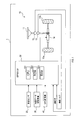
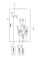
- An electric power steering system (hereinafter referred to as an EPS system) 1 shown in FIG. 1 is a system for assisting a steering operation of a driver of a vehicle.
- the vehicle on which the EPS system 1 is mounted is referred to as “own vehicle”.
- the EPS system 1 includes a steering mechanism 10, a vehicle speed sensor 20, a map data storage device 30, a GPS receiver 40, and an electric power steering ECU (hereinafter referred to as EPSECU) 50.
- the steering mechanism 10 includes a steering wheel 11, a steering angle sensor 12, a torque sensor 13, a motor 14, and steering wheels 15a and 15b.
- the steering wheel 11 is a rotatable member and is rotated by a driver when a steering operation is performed.
- the steering angle sensor 12 is a sensor for detecting the steering angle of the steering wheel 11.
- the steering angle sensor 12 outputs the detection result to the EPS ECU 50.
- the torque sensor 13 is a sensor for detecting steering torque. The torque sensor 13 outputs the detection result to the EPS ECU 50.
- the motor 14 is a power source that supports the steering force of the steering wheel 11 by the driver.
- the motor 14 is driven by the EPS ECU 50 as will be described later.
- the steered wheels 15a and 15b are steered according to the operation of the steering wheel 11 by the driver.
- the vehicle speed sensor 20 is a sensor for detecting the traveling speed of the host vehicle.
- the vehicle speed sensor 20 outputs the detection result to the EPS ECU 50.
- the map data storage device 30 is a device configured to store map data representing a map.
- the map data storage device 30 outputs the map data to the EPS ECU 50.
- the map represented by the map data includes road shape information.
- the GPS receiver 40 is a device configured to identify the current position of the host vehicle by receiving a radio wave transmitted from an artificial satellite for GPS via a GPS antenna (not shown). The GPS receiver 40 outputs the current position of the host vehicle to the EPS ECU 50.
- the EPSECU 50 includes a microcomputer including a CPU 551, a ROM 552, a RAM 553, and the like as constituent elements.
- the EPS ECU 50 calculates the driving amount of the motor 14 and controls the motor 14 according to the calculation result, thereby assisting the driver in rotating the steering wheel 11 and thus in turning the steering wheels 15a and 15b. To do.
- the EPS ECU 50 calculates a target steering angle as steering assistance for assisting a part of the steering operation of the driver, and executes control for biasing the rotation of the steering wheel 11 so that the steering angle becomes the target steering angle.
- the target steering angle here is a target steering angle that is estimated as a steering angle after a predetermined time has elapsed from the present time. This steering assistance is started or ended by an operation based on the driver's intention.
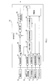
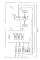
- the EPSECU 50 Various functions of the EPSECU 50 are realized by the CPU 551 executing a program stored in a non-transitional physical storage medium such as the ROM 552. By executing this program, a method corresponding to the program is executed. Further, by executing this program, a steering assist process shown in FIGS. 5 and 6 to be described later is executed. Then, the EPS ECU 50 executes the steering support process, thereby, as shown in FIG. 2, a vehicle speed acquisition unit 51, a map acquisition unit 52, a position acquisition unit 53, a steering angle acquisition unit 54, a torque acquisition unit 55, a basic calculation.
- EPSECU50 Functions as a unit 56, a position prediction unit 57, a steering angle calculation unit 58, an assist calculation unit 59, an adjustment unit 60, an addition unit 61, and an execution unit 62.
- EPSECU50 is provided with the motor drive circuit 63 which is a hardware structure.
- the vehicle speed acquisition unit 51 acquires the traveling speed of the host vehicle from the vehicle speed sensor 20.
- the map acquisition unit 52 acquires map data from the map data storage device 30.
- the position acquisition unit 53 acquires the current position of the host vehicle from the GPS receiver 40.
- the steering angle acquisition unit 54 acquires the steering angle from the steering angle sensor 12.
- the torque acquisition unit 55 acquires the steering torque from the torque sensor 13.
- the basic calculation unit 56 performs control in the control for reducing the load when the driver rotates the steering wheel 11 based on the steering torque acquired by the torque acquisition unit 55 and the traveling speed of the host vehicle acquired by the vehicle speed acquisition unit 51.
- a basic control amount that is a quantity is calculated.
- This basic control amount is a control amount that is calculated even in a normal power steering system in which steering assistance cannot be executed.
- the basic control amount is calculated to increase as the steering torque increases. That is, the basic control amount is calculated so that the steering torque by the motor 14 in the direction that supports the rotation of the steering wheel 11 is increased. Further, the basic control amount is calculated so as to decrease as the traveling speed of the host vehicle increases.
- the motor 14 generates an auxiliary steering torque corresponding to the steering torque applied to the steering wheel 11.
- the position predicting unit 57 is based on the traveling speed of the host vehicle acquired by the vehicle speed acquiring unit 51, the map represented by the map data acquired by the map acquiring unit 52, and the current position of the host vehicle acquired by the position acquiring unit 53. Calculate the predicted position.
- the predicted position is the position of the host vehicle on the map after a predetermined time has elapsed from the present time. In other words, the predicted position is the position of the host vehicle on the map at a predetermined time after the current time.
- the position prediction unit 57 calculates the position of the host vehicle on the map after traveling for a predetermined time along the road on the map from the current position at the acquired traveling speed as the predicted position.
- the steering angle calculation unit 58 calculates a target steering angle based on the road shape at the predicted position that can be specified by the map represented by the map data acquired by the map acquisition unit 52.
- the steering angle calculation unit 58 calculates the curvature of the road at the predicted position based on the road shape, and in other words, the vehicle travels on the road having the curvature corresponding to the calculated curvature.
- the steering angle required at the time is calculated as the target steering angle.
- the assist calculation unit 59 calculates an assist control amount based on the steering angle acquired by the steering angle acquisition unit 54 and the target steering angle calculated by the steering angle calculation unit 58.
- the assist control amount is control executed in steering assist and is a control amount in control for assisting a driver's steering force.
- This assist control amount is calculated as a control amount according to the difference between the acquired steering angle and the calculated target steering angle. Note that the assist control amount here includes not only the magnitude of the assisting control force but also the steering direction.
- the adjusting unit 60 adjusts the assist control amount calculated by the assist calculating unit 59 according to the steering torque acquired by the torque acquiring unit 55. In other words, the adjusting unit 60 adjusts the assist control amount according to the operation amount of the driver's steering operation.
- the adjustment unit 60 includes a gain calculation unit 601 and a multiplication unit 602.
- the gain calculation unit 601 calculates an adjustment gain that takes a value from 0 to 1 according to the steering torque.
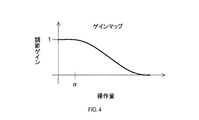
- the adjustment gain is calculated according to the gain map shown in FIG.
- the horizontal axis of the gain map represents the operation amount of the driver, and in this embodiment represents the steering torque.
- the vertical axis represents the adjustment gain.
- the adjustment gain is calculated to be one.
- the adjustment gain is calculated so as to decrease as the steering torque increases. Specifically, the adjustment gain is maintained at 1 in a range where the steering torque is less than a predetermined threshold value ⁇ greater than 0.
- the adjustment gain is calculated to gradually decrease (that is, monotonously decrease) as the steering torque increases.
- the threshold value ⁇ is set as an upper limit value of a range set in advance as a range in which the amount of steering operation by the driver is very small.
- the adjustment gain is calculated based on the magnitude of the steering torque without considering the steering direction of the steering torque in the calculation of the adjustment gain.
- the multiplication unit 602 multiplies the assist control amount calculated by the assist calculation unit 59 and the adjustment gain calculated by the gain calculation unit 601. Thereby, the assist control amount is adjusted.
- the adjustment control gain is 1 in the range where the steering torque is equal to or less than the threshold value ⁇ , and thus the assist control amount is not adjusted.
- the adjustment gain is gradually decreased as the steering torque is increased, so that the assist control amount is adjusted to be smaller.
- the adding unit 61 adds the basic control amount calculated by the basic calculating unit 56 and the assist control amount adjusted by the adjusting unit 60.
- the execution unit 62 executes steering control based on the control amount obtained by addition by the addition unit 61. Specifically, the execution unit 62 executes steering control by controlling the amount of power supplied to the motor 14 by the motor drive circuit 63.
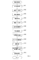
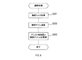
- the motor drive circuit 63 drives the motor 14 by supplying electric power to the motor 14. [1-2. processing] Next, steering assistance processing executed by the EPS ECU 50 will be described with reference to FIGS. Note that the steering support process is executed when the steering support is started, and is ended when the steering support is ended.
- the EPS ECU 50 acquires the traveling speed of the host vehicle from the vehicle speed sensor 20.
- the EPS ECU 50 acquires map data from the map data storage device 30.
- the EPS ECU 50 acquires the current position of the host vehicle from the GPS receiver 40. In S104, the EPS ECU 50 acquires the steering angle from the steering angle sensor 12.
- the EPS ECU 50 acquires the steering torque from the torque sensor 13.
- the EPS ECU 50 calculates a basic control amount based on the traveling speed of the host vehicle acquired in S101 and the steering torque acquired in S105.
- the EPS ECU 50 calculates the predicted position based on the traveling speed of the host vehicle acquired in S101, the map represented by the map data acquired in S102, and the current position of the host vehicle acquired in S103.
- the EPS ECU 50 calculates the target steering angle based on the road shape at the predicted position that can be specified by the map represented by the map data acquired in S102. In S109, the EPS ECU 50 calculates an assist control amount based on the steering angle acquired in S104 and the target steering angle calculated in S108.
- the EPS ECU 50 executes the adjustment process shown in FIG.
- the assist control amount is adjusted by executing the adjustment process.
- the adjustment process will be described.
- the EPS ECU 50 acquires the steering torque from the torque sensor 13.
- the EPS ECU 50 calculates an adjustment gain according to the steering torque acquired in S201.
- the EPS ECU 50 adjusts the assist control amount by multiplying the assist control amount calculated in S109 by the adjustment gain calculated in S202.
- the EPSECU 50 ends the adjustment process when executing S203, and proceeds to S111.
- the EPS ECU 50 adds the basic control amount calculated in S106 and the assist control amount adjusted in S110.
- the EPS ECU 50 executes steering control based on the control amount obtained by addition in S111. Specifically, the EPS ECU 50 executes steering control by controlling the amount of power supplied to the motor 14.
- the process proceeds to S101 described above.
- the EPS ECU 50 corresponds to the steering assist device
- the steering torque detected by the torque sensor 13 corresponds to the operation amount of the steering operation of the driver
- the torque acquisition unit 55 corresponds to the operation amount acquisition unit.
- S101 corresponds to processing as the vehicle speed acquisition unit 51
- S102 corresponds to processing as the map acquisition unit 52 and acquisition of map data
- S103 corresponds to processing as the position acquisition unit 53
- S104 This corresponds to the processing as the steering angle acquisition unit 54.
- S105 and S201 correspond to processing as the torque acquisition unit 55
- S106 corresponds to processing as the basic calculation unit 56
- S107 corresponds to processing as the position prediction unit 57 and calculation of the predicted position
- S108 corresponds to the processing as the steering angle calculation unit 58.
- S109 corresponds to the processing as the assist calculation unit 59 and the assist control amount
- S111 corresponds to the processing as the addition unit 61
- S112 executes the processing and steering control as the execution unit 62. It corresponds to.
- S201 corresponds to acquiring the process and the operation amount as the operation amount acquisition unit
- S202 and S203 correspond to adjusting the process and the assist control amount as the adjustment unit 60, specifically, S202.
- Corresponds to the processing as the gain calculation unit 601 and S203 corresponds to the processing as the multiplication unit 602.
- the assist control amount is adjusted according to the steering torque.
- the assist control amount is adjusted according to the operation amount of the steering operation of the driver. Therefore, when the driver tries to deal with a situation that is not taken into account in the calculation of the assist control amount executed in S109, such as when the driver suddenly performs a steering operation in order to avoid an obstacle, the driver's steering operation is not performed. It is possible to suppress obstruction by steering control.
- steering torque is used for the process of adjusting the assist control amount. Therefore, it is possible to further reduce the driver's uncomfortable feeling when the driver tries to deal with a situation not taken into account in the calculation of the assist control amount.
- the lateral acceleration of the host vehicle is adopted as information representing the operation amount of the steering operation of the driver, and the assist control amount is adjusted according to the lateral acceleration.
- the steering torque reflects the driver's steering operation more accurately than information such as lateral acceleration. Therefore, by using the steering torque for the calculation of the assist control amount, it is possible to adjust the assist control amount that reflects the driver's steering operation more accurately than the configuration using the lateral acceleration of the host vehicle. As a result, the driver's uncomfortable feeling can be further reduced.
- the driver's steering operation can be suppressed from being hindered by the steering control as the driver becomes more pressing. That is, in general, it is considered that as the driver becomes more pressing, the driver rotates the steering wheel 11 more powerfully and the steering torque increases.
- the assist control amount is adjusted to decrease as the steering torque increases. Accordingly, the assist control amount is adjusted to be smaller as the driver is more imminent, and as a result, the driver's steering operation can be further prevented from being hindered by the steering control.
- the assist control amount is not adjusted when the steering torque is equal to or less than the threshold value ⁇ .
- a range set in advance as a range in which the driver's operation amount is very small is set as a dead zone in which the assist control amount is not adjusted.
- the adjustment gain is calculated based on the magnitude of the steering torque, and the steering direction of the steering torque is not considered in the calculation of the adjustment gain.
- the calculated adjustment gain differs according to the difference between the steering direction of the steering torque and the steering direction of the assist control amount.
- the steering direction of the steering torque is a steering direction in which the steering torque is applied by the driver's steering operation, and coincides with the steering direction of the steering operation by the driver.
- the steering direction of the assist control amount here is a steering direction in which steering is assisted by steering assistance, that is, a direction in which steering torque is applied by steering assistance.
- the EPS system 1 of the second embodiment has the same hardware configuration as the EPS system 1 of the first embodiment described above.
- the adjustment process executed by the EPSECU 50 of the second embodiment in other words, the function of the adjustment unit 60 is different from that of the first embodiment.
- functions other than the adjustment part 60 in EPSECU50, such as the vehicle speed acquisition part 51, are the same as 1st Embodiment.
- the adjustment unit 60 of the second embodiment replaces the gain calculation unit 601 and the multiplication unit 602 of the first embodiment with a same direction gain calculation unit 603, a reverse direction gain calculation unit. 604, a determination unit 605, a switch unit 606, and a multiplication unit 607 are provided.
- the same direction gain calculation unit 603 calculates an adjustment gain according to the steering torque acquired by the torque acquisition unit 55.
- the adjustment gain calculated by the same direction gain calculation unit 603 is also referred to as “the same direction gain”.
- the same direction gain is an adjustment gain used when the steering direction of the steering torque and the steering direction of the assist control amount are the same direction.
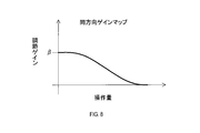
- the same direction gain is calculated according to the same direction gain map shown in FIG. As can be seen from FIG. 8, when the steering torque is 0, the same direction gain is calculated to a predetermined value ⁇ smaller than 1. Further, the same-direction gain is calculated so as to decrease as the steering torque increases. In the same direction gain map, the range of the operation amount in which the adjustment gain is maintained at 1, that is, the dead zone is not set.
- the reverse direction gain calculation unit 604 calculates an adjustment gain according to the steering torque acquired by the torque acquisition unit 55.
- the adjustment gain calculated by the reverse gain calculation unit 604 is also referred to as “reverse gain”.
- the reverse direction gain is an adjustment gain used when the steering direction of the steering torque and the steering direction of the assist control amount are in the reverse direction.
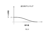
- the reverse gain is calculated according to the reverse gain map shown in FIG. As can be seen from FIG. 9, when the steering torque is 0, the reverse gain is calculated to a predetermined value ⁇ smaller than the above-mentioned predetermined value ⁇ . Further, the reverse gain is calculated so as to decrease as the steering torque increases. In particular, the reverse gain is set to be smaller than the same direction gain with respect to an operation amount of an arbitrary driver's steering operation in which the reverse gain is larger than 0, that is, an arbitrary steering torque value. . Note that no dead zone is set in the reverse gain map.
- the determination unit 605 determines whether or not the steering direction of the steering torque acquired from the torque acquisition unit 55 and the steering direction of the assist control amount calculated by the assist calculation unit 59 are the same direction. That is, the determination unit 605 determines whether or not the steering direction of the steering operation by the driver and the direction in which the steering is supported by the steering support are the same direction.
- the switch unit 606 determines the adjustment gain to be multiplied by the assist control amount as one of the in-direction gain and the reverse direction gain. Specifically, when the determination unit 605 determines that the steering direction of the steering torque and the steering direction of the assist control amount are the same direction, the switch unit 606 applies the adjustment gain multiplied by the assist control amount to the same direction gain. To decide. On the other hand, the switch unit 606 reverses the adjustment gain multiplied by the assist control amount when the determination unit 605 determines that the steering direction of the steering torque and the steering direction of the assist control amount are not the same direction, that is, the reverse direction. Determine the direction gain.
- the multiplication unit 607 multiplies the assist control amount calculated by the assist calculation unit 59 and the adjustment gain determined by the switch unit 606. Thereby, the assist control amount is adjusted.
- the reverse gain is set to be smaller than the same gain. Therefore, the assist control amount is adjusted to be smaller in the case where the steering direction of the steering torque and the steering direction of the assist control amount are opposite to each other than in the same direction.
- the EPS ECU 50 acquires the steering torque from the torque sensor 13. In S302, the EPS ECU 50 calculates the same direction gain according to the steering torque acquired in S301.
- the EPS ECU 50 calculates a reverse gain according to the steering torque acquired in S301.
- the EPS ECU 50 determines whether or not the steering direction of the steering torque acquired in S301 and the steering direction of the assist control amount calculated in S109 of FIG. 5 described above are the same direction. If it is determined in S304 that the steering direction of the steering torque and the steering direction of the assist control amount are the same direction, the process proceeds to S305. On the other hand, if it is determined that the steering direction of the steering torque and the steering direction of the assist control amount are not the same direction, that is, the opposite direction, the process proceeds to S306.
- the EPS ECU 50 determines the adjustment gain to be multiplied by the assist control amount as the same direction gain. In S306, the EPS ECU 50 determines an adjustment gain to be multiplied by the assist control amount as a reverse gain.
- the process proceeds to S307.
- the EPS ECU 50 adjusts the assist control amount by multiplying the assist control amount calculated in S109 of FIG. 5 and the adjustment gain determined in S305 or S306.
- S301 corresponds to acquiring the processing and the operation amount as the torque acquisition unit 55 and the operation amount acquisition unit, and S302 to S307 adjust the processing and the assist control amount as the adjustment unit 60. It corresponds to.
- S302 corresponds to processing as the same direction gain calculation unit 603
- S303 corresponds to processing as the reverse direction gain calculation unit 604, and
- S304 corresponds to processing as the determination unit 605.
- S305 and S306 correspond to processing as the switch unit 606, and S307 corresponds to processing as the multiplication unit 607.
- the configuration of the present embodiment it is possible to further reduce the driver's resistance caused by the steering control when the driver tries to deal with a situation that is not taken into account in the calculation of the assist control amount.
- the magnitude is the same when the steering direction of the driver and the steering direction of the assist control amount are the same direction and when the steering direction of the driver and the steering direction of the assist control amount are opposite directions. Even if the assist control amount is adjusted, the resistance of the driver is different. Specifically, the driver feels resistance when the steering direction of the driver is opposite to the steering direction of the assist control amount.
- the steering direction of the steering torque that is, the steering direction of the driver's steering operation and the steering direction of the assist control amount are opposite
- the assist control amount is adjusted to be smaller than when the control amount is steered in the same direction. In other words, the assist control amount is adjusted to be smaller when the driver feels more resistance. Therefore, it is possible to further reduce the driver's resistance feeling due to the steering control when the driver tries to deal with a situation not taken into account in the calculation of the assist control amount.
- the method of adjusting the assist control amount is changed according to the difference between the steering direction of the steering torque and the steering direction of the assist control amount.
- the third embodiment is different from the second embodiment in that the method of adjusting the assist control amount is changed according to the difference between the steering direction of the steering torque and the steering direction of the motor 14. .
- the EPS system 2 of the third embodiment shown in FIG. 11 includes a steering mechanism 21 instead of the steering mechanism 10 of the second embodiment described above.
- EPSECU50 of 3rd Embodiment performs the process partially different from EPSECU50 of 2nd Embodiment.
- the steering mechanism 21 is different from the steering mechanism 10 of the second embodiment in that it further includes a rotation direction sensor 22 in addition to the components from the steering wheel 11 to the steering wheels 15a and 15b.
- the rotation direction sensor 22 detects the rotation direction of the motor 14.
- the rotation direction sensor 22 outputs the detection result to the EPS ECU 50.
- the EPS ECU 50 of the third embodiment has a function as a rotation acquisition unit 64 in addition to the functions from the vehicle speed acquisition unit 51 to the execution unit 62 described above. Different from the EPSECU 50. Further, the adjustment unit 60 of the third embodiment is partially different in function from the adjustment unit 60 of the second embodiment.
- the rotation acquisition unit 64 acquires the rotation direction of the motor 14 from the rotation direction sensor 22, and thus the direction in which the steering torque is applied by the motor 14 (hereinafter, the steering direction of the motor 14).
- the adjustment unit 60 of the third embodiment has the functions from the above-described same-direction gain calculation unit 603 to the multiplication unit 607, and among these, the functions of the determination unit 605 and the switch unit 606 are It differs from the adjustment part 60 of 2 embodiment.
- the determination unit 605 determines whether the steering direction of the steering torque acquired by the torque acquisition unit 55 and the steering direction of the motor 14 acquired by the rotation acquisition unit 64 are the same direction.
- the switch unit 606 determines an adjustment gain to be multiplied by the assist control amount as one of the in-direction gain and the reverse direction gain. Specifically, when the determination unit 605 determines that the steering direction of the steering torque and the steering direction of the motor 14 are the same direction, the switch unit 606 sets the adjustment gain multiplied by the assist control amount to the same direction gain. decide. On the other hand, when the determination unit 605 determines that the steering direction of the steering torque and the steering direction of the motor 14 are not the same direction, that is, the reverse direction, the switch unit 606 reverses the adjustment gain multiplied by the assist control amount. Determine the gain.
- step S ⁇ b> 404 the EPS ECU 50 acquires the rotation direction of the motor 14 and thus the steering direction of the motor 14 from the rotation direction sensor 22.
- the EPS ECU 50 determines whether or not the steering direction of the steering torque acquired in S401 and the steering direction of the motor 14 acquired in S404 are the same direction. If it is determined in S405 that the steering direction of the steering torque and the steering direction of the motor 14 are the same direction, the process proceeds to S406. On the other hand, if it is determined that the steering direction of the steering torque and the steering direction of the motor 14 are not the same direction, that is, the opposite direction, the process proceeds to S407.
- S406 to S408 are the same as S305 to S307 in FIG. 10 described above, description thereof will be omitted.
- S401 corresponds to acquiring the processing and operation amount as the torque acquisition unit 55 and the operation amount acquisition unit
- S404 corresponds to processing as the rotation acquisition unit 64
- S402, S403, and S405 to S408 are adjustment units. This corresponds to adjusting the processing and the assist control amount as 60.
- S402 corresponds to processing as the same direction gain calculation unit 603
- S403 corresponds to processing as the reverse direction gain calculation unit 604
- S405 corresponds to processing as the determination unit 605.
- S406 and S407 correspond to processing as the switch unit 606, and S408 corresponds to processing as the multiplication unit 607.
- the steering direction of the steering torque that is, the steering direction of the driver's steering operation and the steering direction of the motor 14 are opposite directions
- the steering direction of the driver's steering operation and the steering of the assist control amount are performed.
- the assist control amount is adjusted to be smaller than when the direction is the same direction. Therefore, the same effect as that of the second embodiment described above can be obtained.
- the assist control amount is adjusted to be smaller as the steering torque, that is, the operation amount of the driver's steering operation is larger.
- the method of adjusting the assist control amount is limited to this. is not.
- the assist control amount may be adjusted to be uniformly small, for example, multiplied by a constant adjustment gain regardless of the magnitude of the driver's steering operation amount. In this case, the assist control amount is adjusted according to the presence or absence of an operation amount of the driver's steering operation.
- the dead zone is set in the gain map.
- the dead zone is not set in both the in-direction gain map and the reverse direction gain map.
- the presence or absence of setting is not limited to this.
- the dead zone may not be set in the gain map.
- a dead zone may be set in at least one of the same direction gain map and the reverse direction gain map.
- the steering torque that is a detected value of the torque sensor 13 is exemplified as the operation amount of the driver's steering operation, but the operation amount is not limited to this.
- the operation amount of the steering operation of the driver may be, for example, the rotational speed of the steering wheel 11 and the rotational speed of the motor 14. Also in this case, it is possible to adjust the assist control amount that more accurately reflects the driver's steering operation as compared with the configuration using the lateral acceleration of the host vehicle as the operation amount of the driver's steering operation. As a result, the driver's uncomfortable feeling can be further reduced.
- part or all of the functions executed by the EPSECU 50 may be configured in hardware by one or a plurality of ICs.
- the functions of the map acquisition unit 52, the position acquisition unit 53, the position prediction unit 57, and the steering angle calculation unit 58 may be configured by devices outside the EPS ECU 50.
- EPS systems 1 and 2 having the EPSECU 50 as constituent elements a program for causing the computer to function as the EPSECU 50, a non-transitional physical storage medium such as a semiconductor memory storing the program, a driver
- a non-transitional physical storage medium such as a semiconductor memory storing the program
- the present disclosure can also be realized in various forms such as a method of adjusting the assist control amount according to the operation amount of the steering operation.
Abstract
位置予測部(57,S107)は、地図に基づいて、現時点よりも後の所定の時点における地図上の車両の位置である予測位置を演算する。アシスト演算部(59,S109)は、地図により特定可能な前記予測位置における道路形状に基づき、操舵操作のアシスト制御量を演算する。操作量取得部(55,S201,S301,S401)は、操舵操作の操作量を取得する。調節部(60,601~607,S202,S203,S302~S307,S402~S408)は、操作量に応じて、アシスト制御量を調節する。
Description
本国際出願は、2016年8月1日に日本国特許庁に出願された日本国特許出願第2016-151210号に基づく優先権を主張するものであり、日本国特許出願第2016-151210号の全内容を本国際出願に参照により援用する。
本開示は、車両のドライバの操舵操作を支援する技術に関する。
車両のドライバの操舵操作を支援するように構成された操舵支援装置が知られている。特許文献1に記載の操舵支援装置では、車両内の地図データベースに記憶された道路の勾配情報に基づいて、ドライバが道路の前方を見通せない状態から見通せる状態に変化する地点である見通し地点が設定される。そして、車両が見通し地点を通過した後においてドライバが前方を見通せるようになったときに慌てて操舵操作を急激に行ったことで操舵輪の舵角が急激に変化しないように、操舵比を調節する操舵制御が行われる。なお、ここでいう操舵比とは、操舵輪の舵角に対するステアリングホイールの回転角度の割合である。
ところで、現時点のステアリングホイールの操舵角と、現時点から所定時間経過した後の操舵角として推定される、目標となる操舵角である目標操舵角と、に基づいて、アシスト制御量を演算する操舵支援装置が考えられる。アシスト制御量は、ドライバの操舵力をアシストする制御における制御量である。また、ここでいうアシスト制御量には、アシストする制御の力の大きさだけでなく、その操舵方向も含まれる。そして、事前に取得された道路形状の情報等に基づいて目標操舵角、ひいては、アシスト制御量を演算し、そのアシスト制御量に基づいて操舵制御を実行する構成が考えられる。
しかしながら、発明者の詳細な検討の結果、このような構成において、以下の課題が見出された。すなわち、障害物を回避しようとしてドライバが操舵操作を急激に行う場合など、アシスト制御量の演算において加味されていない状況にドライバが対処しようとした際に、ドライバの操舵操作が操舵制御によって妨げられる可能性があるという課題が見出された。
本開示の一局面は、アシスト制御量の演算において加味されていない状況にドライバが対処しようとした際に、ドライバの操舵操作が操舵制御によって妨げられることを抑制する技術を提供することにある。
本開示の一態様は、車両のドライバの操舵操作を支援するように構成された操舵支援装置であって、地図取得部と、位置予測部と、アシスト演算部と、操作量取得部と、調節部と、実行部と、を備える操舵支援装置である。地図取得部は、地図を表す地図データを取得する。位置予測部は、地図に基づいて、現時点よりも後の所定の時点における地図上の車両の位置である予測位置を演算する。アシスト演算部は、地図により特定可能な予測位置における道路形状に基づき、操舵操作のアシスト制御量を演算する。操作量取得部は、操舵操作の操作量を取得する。調節部は、操作量に応じて、アシスト制御量を調節する。実行部は、調節部により調節されたアシスト制御量に基づいて、操舵制御を実行する。
このような構成によれば、ドライバの操作量に応じてアシスト制御量が調節される。このため、アシスト制御量の演算において加味されていない状況にドライバが対処しようとした際に、ドライバの操舵操作が操舵制御によって妨げられることを抑制することができる。
本開示の別の態様は、車両のドライバの操舵操作を支援するように構成された操舵支援装置により実行される操舵支援方法である。操舵支援方法は、地図を表す地図データを取得すること、及び、地図に基づいて、現時点よりも後の所定の時点における地図上の車両の位置である予測位置を演算すること、を含む。また、操舵支援方法は、地図により特定可能な予測位置における道路形状に基づき、操舵操作のアシスト制御量を演算すること、及び、操舵操作の操作量を取得すること、を含む。さらに、操舵支援方法は、操作量に応じて、アシスト制御量を調節すること、及び、調節されたアシスト制御量に基づいて、操舵制御を実行すること、を含む。
このような方法によれば、上記操舵支援装置と同様の効果を奏する。
なお、請求の範囲に記載した括弧内の符号は、一つの態様として後述する実施形態に記載の具体的手段との対応関係を示すものであって、本開示の技術的範囲を限定するものではない。
なお、請求の範囲に記載した括弧内の符号は、一つの態様として後述する実施形態に記載の具体的手段との対応関係を示すものであって、本開示の技術的範囲を限定するものではない。
以下、図面を参照しながら、本開示を実施するための形態を説明する。
[1.第1実施形態]
[1-1.構成]
図1に示す電動パワーステアリングシステム(以下、EPSシステム)1は、車両のドライバの操舵操作を支援するためのシステムである。EPSシステム1が搭載された車両を以下では「自車両」という。EPSシステム1は、操舵機構10、車速センサ20、地図データ記憶装置30、GPS受信機40及び電動パワーステアリングECU(以下、EPSECU)50を備える。
[1.第1実施形態]
[1-1.構成]
図1に示す電動パワーステアリングシステム(以下、EPSシステム)1は、車両のドライバの操舵操作を支援するためのシステムである。EPSシステム1が搭載された車両を以下では「自車両」という。EPSシステム1は、操舵機構10、車速センサ20、地図データ記憶装置30、GPS受信機40及び電動パワーステアリングECU(以下、EPSECU)50を備える。
操舵機構10は、ステアリングホイール11、操舵角センサ12、トルクセンサ13、モータ14及び操舵輪15a,15bを備える。
ステアリングホイール11は、回転可能な部材であり、操舵操作が行われる際にドライバによって回転される。
ステアリングホイール11は、回転可能な部材であり、操舵操作が行われる際にドライバによって回転される。
操舵角センサ12は、ステアリングホイール11の操舵角を検出するためのセンサである。操舵角センサ12は、検出結果をEPSECU50に出力する。
トルクセンサ13は、操舵トルクを検出するためのセンサである。トルクセンサ13は、検出結果をEPSECU50に出力する。
トルクセンサ13は、操舵トルクを検出するためのセンサである。トルクセンサ13は、検出結果をEPSECU50に出力する。
モータ14は、ドライバによるステアリングホイール11の操舵力を支援する動力源である。モータ14は、後述するように、EPSECU50によって駆動される。
操舵輪15a,15bは、ドライバによるステアリングホイール11の操作に応じて転舵される。
操舵輪15a,15bは、ドライバによるステアリングホイール11の操作に応じて転舵される。
一方、車速センサ20は、自車両の走行速度を検出するためのセンサである。車速センサ20は、検出結果をEPSECU50に出力する。
地図データ記憶装置30は、地図を表す地図データを記憶するように構成された装置である。地図データ記憶装置30は、地図データをEPSECU50に出力する。地図データが表す地図には、道路形状の情報が含まれる。
地図データ記憶装置30は、地図を表す地図データを記憶するように構成された装置である。地図データ記憶装置30は、地図データをEPSECU50に出力する。地図データが表す地図には、道路形状の情報が含まれる。
GPS受信機40は、GPS用の人工衛星からの送信電波を図示しないGPSアンテナを介して受信することにより自車両の現在位置を特定するように構成された装置である。GPS受信機40は、自車両の現在位置をEPSECU50に出力する。
EPSECU50は、CPU551、ROM552及びRAM553等を構成要素とするマイクロコンピュータを備える。EPSECU50は、モータ14の駆動量を演算し、その演算結果に応じてモータ14を制御することにより、ドライバがステアリングホイール11を回転させる力、ひいては、操舵輪15a,15bを転舵させる力を支援する。
また、このEPSECU50は、ドライバの操舵操作の一部を支援する操舵支援として、目標操舵角を演算し、操舵角が目標操舵角となるように、ステアリングホイール11の回転を付勢する制御を実行する。ここでいう目標操舵角とは、現時点から所定時間経過した後の操舵角として推定される、目標となる操舵角である。この操舵支援は、ドライバの意思に基づく操作によって開始又は終了される。
EPSECU50の各種機能は、CPU551がROM552等の非遷移的実体的記憶媒体に格納されているプログラムを実行することにより実現される。このプログラムが実行されることで、プログラムに対応する方法が実行される。また、このプログラムが実行されることで、後述する図5及び図6に示す操舵支援処理が実行される。そして、EPSECU50は、この操舵支援処理を実行することにより、図2に示すように、車速取得部51、地図取得部52、位置取得部53、操舵角取得部54、トルク取得部55、基本演算部56、位置予測部57、操舵角演算部58、アシスト演算部59、調節部60、加算部61及び実行部62として機能する。また、EPSECU50は、ハードウェア構成であるモータ駆動回路63を備える。
車速取得部51は、車速センサ20から自車両の走行速度を取得する。
地図取得部52は、地図データ記憶装置30から地図データを取得する。
位置取得部53は、GPS受信機40から自車両の現在位置を取得する。
地図取得部52は、地図データ記憶装置30から地図データを取得する。
位置取得部53は、GPS受信機40から自車両の現在位置を取得する。
操舵角取得部54は、操舵角センサ12から操舵角を取得する。
トルク取得部55は、トルクセンサ13から操舵トルクを取得する。
基本演算部56は、トルク取得部55により取得された操舵トルク及び車速取得部51により取得された自車両の走行速度に基づき、ドライバがステアリングホイール11を回転させる際の負荷を軽減する制御における制御量である基本制御量を演算する。この基本制御量は、操舵支援が実行可能でない通常のパワーステアリングシステムにおいても演算される制御量である。具体的には、操舵トルクが大きいほど基本制御量は大きくなるように演算される。つまり、ステアリングホイール11の回転を支援する方向のモータ14による操舵トルクが大きくなるように基本制御量は演算される。また、自車両の走行速度が大きいほど基本制御量は小さくなるよう演算される。このように、ステアリングホイール11に加えられる操舵トルクに応じた補助操舵トルクをモータ14は発生させる。
位置予測部57は、車速取得部51により取得された自車両の走行速度、地図取得部52により取得された地図データが表す地図及び位置取得部53により取得された自車両の現在位置に基づき、予測位置を演算する。予測位置は、現時点から所定時間経過した後の地図上の自車両の位置である。換言すれば、この予測位置は、現時点よりも後の所定の時点における地図上の自車両の位置である。具体的には、位置予測部57は、取得された走行速度で現在位置から地図上の道路に沿って所定時間走行した後の地図上の自車両の位置を予測位置として演算する。
操舵角演算部58は、地図取得部52により取得された地図データが表す地図により特定可能な予測位置における道路形状に基づき、目標操舵角を演算する。本実施形態では、操舵角演算部58は、道路形状に基づき予測位置における道路の曲率を演算し、演算された曲率に見合った操舵角、換言すれば、その曲率の道路を自車両が走行する際に必要となる操舵角、を目標操舵角として演算する。
アシスト演算部59は、操舵角取得部54により取得された操舵角及び操舵角演算部58により演算された目標操舵角に基づき、アシスト制御量を演算する。アシスト制御量は、操舵支援において実行される制御であってドライバの操舵力を支援する制御における制御量である。このアシスト制御量は、取得された操舵角と演算された目標操舵角との差分に応じた制御量として演算される。なお、ここでいうアシスト制御量には、アシストする制御の力の大きさだけでなく、その操舵方向も含まれる。
調節部60は、トルク取得部55により取得された操舵トルクに応じて、アシスト演算部59により演算されたアシスト制御量を調節する。換言すれば、調節部60は、ドライバの操舵操作の操作量に応じて、アシスト制御量を調節する。具体的には、調節部60は、図3に示すように、ゲイン演算部601及び乗算部602を備える。
ゲイン演算部601は、操舵トルクに応じて、0から1までの値をとる調節ゲインを演算する。
調節ゲインは、図4に示すゲインマップに従い演算される。ゲインマップの横軸はドライバの操作量を表し、本実施形態では操舵トルクを表す。一方、縦軸は調節ゲインを表す。図4から見て取れるように、操舵トルクが0のときには調節ゲインは1に演算される。また、操舵トルクが大きくなるに従って、調節ゲインは小さくなるように演算される。詳細には、操舵トルクが0よりも大きい所定のしきい値α以下である範囲では、調節ゲインは1に保たれる。一方、操舵トルクがしきい値αよりも大きい範囲では、操舵トルクが大きいほど、調節ゲインが徐々に減少(つまり、単調減少)するように演算される。本実施形態では、しきい値αは、ドライバの操舵操作の操作量が微少である範囲としてあらかじめ設定された範囲の上限値として設定される。
調節ゲインは、図4に示すゲインマップに従い演算される。ゲインマップの横軸はドライバの操作量を表し、本実施形態では操舵トルクを表す。一方、縦軸は調節ゲインを表す。図4から見て取れるように、操舵トルクが0のときには調節ゲインは1に演算される。また、操舵トルクが大きくなるに従って、調節ゲインは小さくなるように演算される。詳細には、操舵トルクが0よりも大きい所定のしきい値α以下である範囲では、調節ゲインは1に保たれる。一方、操舵トルクがしきい値αよりも大きい範囲では、操舵トルクが大きいほど、調節ゲインが徐々に減少(つまり、単調減少)するように演算される。本実施形態では、しきい値αは、ドライバの操舵操作の操作量が微少である範囲としてあらかじめ設定された範囲の上限値として設定される。
なお、このように、本実施形態では、調節ゲインの演算において操舵トルクの操舵方向は考慮されず、操舵トルクの大きさに基づき調節ゲインが演算される。
乗算部602は、アシスト演算部59により演算されたアシスト制御量とゲイン演算部601により演算された調節ゲインとを乗算する。これによりアシスト制御量が調節される。
乗算部602は、アシスト演算部59により演算されたアシスト制御量とゲイン演算部601により演算された調節ゲインとを乗算する。これによりアシスト制御量が調節される。
つまり、本実施形態では、操舵トルクがしきい値α以下である範囲では、調節ゲインが1であるため、アシスト制御量は調節されない。そして、操舵トルクがしきい値αよりも大きい範囲では、操舵トルクが大きいほど、調節ゲインが徐々に減少するため、アシスト制御量が小さくなるように調節される。
加算部61は、基本演算部56により演算された基本制御量と調節部60により調節されたアシスト制御量とを加算する。
実行部62は、加算部61により加算されて得られた制御量に基づき、操舵制御を実行する。具体的には、実行部62は、モータ駆動回路63によるモータ14への電力の供給量を制御することにより、操舵制御を実行する。
実行部62は、加算部61により加算されて得られた制御量に基づき、操舵制御を実行する。具体的には、実行部62は、モータ駆動回路63によるモータ14への電力の供給量を制御することにより、操舵制御を実行する。
モータ駆動回路63は、モータ14に電力を供給することによりモータ14を駆動する。
[1-2.処理]
次に、EPSECU50が実行する操舵支援処理について、図5及び図6を用いて説明する。なお、操舵支援処理は、操舵支援が開始されることにより実行され、操舵支援が終了されることにより終了する。
[1-2.処理]
次に、EPSECU50が実行する操舵支援処理について、図5及び図6を用いて説明する。なお、操舵支援処理は、操舵支援が開始されることにより実行され、操舵支援が終了されることにより終了する。
S101で、EPSECU50は、車速センサ20から自車両の走行速度を取得する。
S102で、EPSECU50は、地図データ記憶装置30から地図データを取得する。
S102で、EPSECU50は、地図データ記憶装置30から地図データを取得する。
S103で、EPSECU50は、GPS受信機40から自車両の現在位置を取得する。
S104で、EPSECU50は、操舵角センサ12から操舵角を取得する。
S104で、EPSECU50は、操舵角センサ12から操舵角を取得する。
S105で、EPSECU50は、トルクセンサ13から操舵トルクを取得する。
S106で、EPSECU50は、S101で取得した自車両の走行速度及びS105で取得した操舵トルクに基づき、基本制御量を演算する。
S106で、EPSECU50は、S101で取得した自車両の走行速度及びS105で取得した操舵トルクに基づき、基本制御量を演算する。
S107で、EPSECU50は、S101で取得した自車両の走行速度、S102で取得した地図データが表す地図及びS103で取得した自車両の現在位置に基づき、予測位置を演算する。
S108で、EPSECU50は、S102で取得した地図データが表す地図により特定可能な予測位置における道路形状に基づき、目標操舵角を演算する。
S109で、EPSECU50は、S104で取得した操舵角及びS108で演算した目標操舵角に基づき、アシスト制御量を演算する。
S109で、EPSECU50は、S104で取得した操舵角及びS108で演算した目標操舵角に基づき、アシスト制御量を演算する。
S110で、EPSECU50は、図6に示す調節処理を実行する。調節処理が実行されることによりアシスト制御量が調節される。
ここで、調節処理について説明する。
ここで、調節処理について説明する。
S201で、EPSECU50は、トルクセンサ13から操舵トルクを取得する。
S202で、EPSECU50は、S201で取得した操舵トルクに応じて調節ゲインを演算する。
S202で、EPSECU50は、S201で取得した操舵トルクに応じて調節ゲインを演算する。
S203で、EPSECU50は、S109で演算したアシスト制御量とS202で演算した調節ゲインとを乗算し、アシスト制御量を調節する。
EPSECU50は、S203を実行すると調節処理を終了し、S111に移行する。
EPSECU50は、S203を実行すると調節処理を終了し、S111に移行する。
S111で、EPSECU50は、S106で演算した基本制御量とS110で調節したアシスト制御量とを加算する。
S112で、EPSECU50は、S111で加算して得られた制御量に基づき、操舵制御を実行する。具体的には、EPSECU50は、モータ14への電力の供給量を制御することにより、操舵制御を実行する。
S112で、EPSECU50は、S111で加算して得られた制御量に基づき、操舵制御を実行する。具体的には、EPSECU50は、モータ14への電力の供給量を制御することにより、操舵制御を実行する。
EPSECU50は、S112を実行すると前述したS101に移行する。
なお、本実施形態では、EPSECU50が操舵支援装置に相当し、トルクセンサ13の検出値である操舵トルクがドライバの操舵操作の操作量に相当し、トルク取得部55が操作量取得部に相当する。また、S101が車速取得部51としての処理に相当し、S102が地図取得部52としての処理及び地図データを取得することに相当し、S103が位置取得部53としての処理に相当し、S104が操舵角取得部54としての処理に相当する。また、S105及びS201がトルク取得部55としての処理に相当し、S106が基本演算部56としての処理に相当し、S107が位置予測部57としての処理及び予測位置を演算することに相当し、S108が操舵角演算部58としての処理に相当する。また、S109がアシスト演算部59としての処理及びアシスト制御量を演算することに相当し、S111が加算部61としての処理に相当し、S112が実行部62としての処理及び操舵制御を実行することに相当する。また、S201が操作量取得部としての処理及び操作量を取得することに相当し、S202及びS203が調節部60としての処理及びアシスト制御量を調節することに相当し、具体的には、S202がゲイン演算部601としての処理に相当し、S203が乗算部602としての処理に相当する。
なお、本実施形態では、EPSECU50が操舵支援装置に相当し、トルクセンサ13の検出値である操舵トルクがドライバの操舵操作の操作量に相当し、トルク取得部55が操作量取得部に相当する。また、S101が車速取得部51としての処理に相当し、S102が地図取得部52としての処理及び地図データを取得することに相当し、S103が位置取得部53としての処理に相当し、S104が操舵角取得部54としての処理に相当する。また、S105及びS201がトルク取得部55としての処理に相当し、S106が基本演算部56としての処理に相当し、S107が位置予測部57としての処理及び予測位置を演算することに相当し、S108が操舵角演算部58としての処理に相当する。また、S109がアシスト演算部59としての処理及びアシスト制御量を演算することに相当し、S111が加算部61としての処理に相当し、S112が実行部62としての処理及び操舵制御を実行することに相当する。また、S201が操作量取得部としての処理及び操作量を取得することに相当し、S202及びS203が調節部60としての処理及びアシスト制御量を調節することに相当し、具体的には、S202がゲイン演算部601としての処理に相当し、S203が乗算部602としての処理に相当する。
[1-3.効果]
以上詳述した第1実施形態によれば、以下の効果が得られる。
(1a)本実施形態では、アシスト制御量は、操舵トルクに応じて調節される。換言すれば、アシスト制御量は、ドライバの操舵操作の操作量に応じて調節される。したがって、障害物を回避しようとしてドライバが操舵操作を急激に行う場合など、S109で実行されるアシスト制御量の演算において加味されていない状況にドライバが対処しようとした際に、ドライバの操舵操作が操舵制御によって妨げられることを抑制することができる。
以上詳述した第1実施形態によれば、以下の効果が得られる。
(1a)本実施形態では、アシスト制御量は、操舵トルクに応じて調節される。換言すれば、アシスト制御量は、ドライバの操舵操作の操作量に応じて調節される。したがって、障害物を回避しようとしてドライバが操舵操作を急激に行う場合など、S109で実行されるアシスト制御量の演算において加味されていない状況にドライバが対処しようとした際に、ドライバの操舵操作が操舵制御によって妨げられることを抑制することができる。
(1b)本実施形態では、アシスト制御量を調節する処理に操舵トルクが用いられる。したがって、アシスト制御量の演算において加味されていない状況にドライバが対処しようとした際の、ドライバの違和感をより軽減することができる。
すなわち、ドライバの操舵操作の操作量を表す情報として、自車両の横加速度を採用し、当該横加速度に応じてアシスト制御量を調節することが考えられる。しかしながら、横加速度といった情報よりも操舵トルクの方が、ドライバの操舵操作をより精度良く反映する。したがって、アシスト制御量の演算に操舵トルクを用いることで、自車両の横加速度を用いる構成と比較して、ドライバの操舵操作をより精度良く反映したアシスト制御量の調節が可能となる。その結果、ドライバの違和感をより軽減することができる。
(1c)本実施形態の構成によれば、ドライバがより切迫した状況になるほど、ドライバの操舵操作が操舵制御によって妨げられることを抑制することができる。
すなわち、一般に、ドライバがより切迫した状況になるほど、ドライバがより力強くステアリングホイール11を回転させ、操舵トルクが大きくなると考えられる。本実施形態では、操舵トルクが大きくなるほど、アシスト制御量が小さくなるように調節される。したがって、ドライバがより切迫した状況になるほど、アシスト制御量が小さくなるように調節され、その結果、ドライバの操舵操作が操舵制御によって妨げられることをより抑制することができる。
すなわち、一般に、ドライバがより切迫した状況になるほど、ドライバがより力強くステアリングホイール11を回転させ、操舵トルクが大きくなると考えられる。本実施形態では、操舵トルクが大きくなるほど、アシスト制御量が小さくなるように調節される。したがって、ドライバがより切迫した状況になるほど、アシスト制御量が小さくなるように調節され、その結果、ドライバの操舵操作が操舵制御によって妨げられることをより抑制することができる。
(1d)本実施形態では、操舵トルクがしきい値α以下である場合には、アシスト制御量は調節されない。換言すれば、ゲインマップにおいて、ドライバの操作量が微少である範囲としてあらかじめ設定された範囲が、アシスト制御量の調節が行われない範囲である不感帯として設定されている。
したがって、ドライバが誤操作によりステアリングホイール11を微少に操作した場合にもアシスト制御量が調節されることを抑制することができる。
[2.第2実施形態]
[2-1.第1実施形態との相違点]
第2実施形態は、基本的な構成は第1実施形態と同様であるため、共通する構成については説明を省略し、相違点を中心に説明する。なお、第1実施形態と同じ符号は、同一の構成を示すものであって、先行する本明細書中の記載及び図面を参照する。
[2.第2実施形態]
[2-1.第1実施形態との相違点]
第2実施形態は、基本的な構成は第1実施形態と同様であるため、共通する構成については説明を省略し、相違点を中心に説明する。なお、第1実施形態と同じ符号は、同一の構成を示すものであって、先行する本明細書中の記載及び図面を参照する。
前述した第1実施形態では、アシスト制御量の調節において、調節ゲインは操舵トルクの大きさに基づき演算され、操舵トルクの操舵方向は調節ゲインの演算において考慮されない。これに対して、第2実施形態では、操舵トルクの操舵方向とアシスト制御量の操舵方向との異同に応じて、演算される調節ゲインが異なる。なお、ここでいう操舵トルクの操舵方向とは、ドライバの操舵操作による操舵トルクがかかっている操舵方向であり、ドライバによる操舵操作の操舵方向と一致する。また、ここでいうアシスト制御量の操舵方向とは、操舵支援によって操舵が支援される操舵方向、つまり、操舵支援によって操舵トルクが加えられる方向である。
具体的には、第2実施形態のEPSシステム1は、前述した第1実施形態のEPSシステム1とハードウェア構成は同一である。しかし、第2実施形態のEPSECU50が実行する調節処理、換言すれば、調節部60の機能が第1実施形態と相違する。なお、車速取得部51などの、EPSECU50における調節部60以外の機能は第1実施形態と同一である。
詳細には、図7に示すように、第2実施形態の調節部60は、第1実施形態のゲイン演算部601及び乗算部602に代えて、同方向ゲイン演算部603、逆方向ゲイン演算部604、判定部605、スイッチ部606及び乗算部607を備える。
同方向ゲイン演算部603は、トルク取得部55により取得された操舵トルクに応じて、調節ゲインを演算する。以下では、同方向ゲイン演算部603により演算される調節ゲインを「同方向ゲイン」ともいう。後述するように、同方向ゲインは、操舵トルクの操舵方向とアシスト制御量の操舵方向とが同一方向である場合に用いられる調節ゲインである。
同方向ゲインは、図8に示す同方向ゲインマップに従い演算される。図8から見て取れるように、操舵トルクが0のときには同方向ゲインは1よりも小さい所定値βに演算される。また、操舵トルクが大きくなるに従って、同方向ゲインは、小さくなるように演算される。なお、同方向ゲインマップでは、調節ゲインが1に保たれる操作量の範囲、換言すれば、不感帯は設定されていない。
一方、逆方向ゲイン演算部604は、トルク取得部55により取得された操舵トルクに応じて、調節ゲインを演算する。以下では、逆方向ゲイン演算部604により演算される調節ゲインを「逆方向ゲイン」ともいう。後述するように、逆方向ゲインは、操舵トルクの操舵方向とアシスト制御量の操舵方向とが逆方向である場合に用いられる調節ゲインである。
逆方向ゲインは、図9に示す逆方向ゲインマップに従い演算される。図9から見て取れるように、操舵トルクが0のときには逆方向ゲインは前述した所定値βよりも小さい所定値γに演算される。また、操舵トルクが大きくなるに従って、逆方向ゲインは、小さくなるように演算される。特に、逆方向ゲインは、当該逆方向ゲインが0よりも大きいような任意のドライバの操舵操作の操作量、つまり任意の操舵トルクの値について、同方向ゲインよりも小さくなるように設定されている。なお、逆方向ゲインマップでも不感帯は設定されていない。
判定部605は、トルク取得部55より取得された操舵トルクの操舵方向と、アシスト演算部59により演算されたアシスト制御量の操舵方向と、が同一方向であるか否かを判定する。つまり、判定部605は、ドライバによる操舵操作の操舵方向と操舵支援によって操舵が支援される方向とが同一方向か否かを判定する。
スイッチ部606は、判定部605の判定結果に基づいて、アシスト制御量に乗じる調節ゲインを、同方向ゲイン及び逆方向ゲインのうちのいずれか一方に決定する。具体的には、スイッチ部606は、判定部605により操舵トルクの操舵方向とアシスト制御量の操舵方向とが同一方向であると判定された場合に、アシスト制御量に乗じる調節ゲインを同方向ゲインに決定する。一方、スイッチ部606は、判定部605により操舵トルクの操舵方向とアシスト制御量の操舵方向とが同一方向でない、つまり逆方向であると判定された場合に、アシスト制御量に乗じる調節ゲインを逆方向ゲインに決定する。
乗算部607は、アシスト演算部59により演算されたアシスト制御量とスイッチ部606により決定された調節ゲインとを乗算する。これによりアシスト制御量が調節される。前述したように逆方向ゲインは同方向ゲインよりも小さくなるように設定されている。このため、操舵トルクの操舵方向とアシスト制御量の操舵方向とが逆方向である場合の方が、同方向である場合よりも、アシスト制御量がより小さくなるように調節される。
[2-2.処理]
次に、第2実施形態のEPSECU50が実行する操舵支援処理について説明する。第2実施形態のEPSECU50が実行する操舵支援処理は、第1実施形態のEPSECU50が実行する操舵支援処理と調節処理を除き同一である。したがって、以下では、相違点に係る調節処理のみを図10のフローチャートを用いて説明する。
次に、第2実施形態のEPSECU50が実行する操舵支援処理について説明する。第2実施形態のEPSECU50が実行する操舵支援処理は、第1実施形態のEPSECU50が実行する操舵支援処理と調節処理を除き同一である。したがって、以下では、相違点に係る調節処理のみを図10のフローチャートを用いて説明する。
S301で、EPSECU50は、トルクセンサ13から操舵トルクを取得する。
S302で、EPSECU50は、S301で取得した操舵トルクに応じて同方向ゲインを演算する。
S302で、EPSECU50は、S301で取得した操舵トルクに応じて同方向ゲインを演算する。
S303で、EPSECU50は、S301で取得した操舵トルクに応じて逆方向ゲインを演算する。
S304で、EPSECU50は、S301で取得した操舵トルクの操舵方向と前述した図5のS109で演算したアシスト制御量の操舵方向とが同一方向であるか否かを判定する。このS304で操舵トルクの操舵方向とアシスト制御量の操舵方向とが同一方向であると判定された場合には処理がS305に移行する。一方、操舵トルクの操舵方向とアシスト制御量の操舵方向とが同一方向でない、つまり、逆方向であると判定された場合には処理がS306に移行する。
S304で、EPSECU50は、S301で取得した操舵トルクの操舵方向と前述した図5のS109で演算したアシスト制御量の操舵方向とが同一方向であるか否かを判定する。このS304で操舵トルクの操舵方向とアシスト制御量の操舵方向とが同一方向であると判定された場合には処理がS305に移行する。一方、操舵トルクの操舵方向とアシスト制御量の操舵方向とが同一方向でない、つまり、逆方向であると判定された場合には処理がS306に移行する。
S305で、EPSECU50は、アシスト制御量に乗じる調節ゲインを同方向ゲインに決定する。
S306で、EPSECU50は、アシスト制御量に乗じる調節ゲインを逆方向ゲインに決定する。
S306で、EPSECU50は、アシスト制御量に乗じる調節ゲインを逆方向ゲインに決定する。
EPSECU50は、S305又はS306を実行するとS307に移行する。
S307で、EPSECU50は、前述した図5のS109で演算したアシスト制御量とS305又はS306で決定された調節ゲインとを乗算し、アシスト制御量を調節する。
S307で、EPSECU50は、前述した図5のS109で演算したアシスト制御量とS305又はS306で決定された調節ゲインとを乗算し、アシスト制御量を調節する。
EPSECU50は、S307を実行すると調節処理を終了する。
なお、本実施形態では、S301がトルク取得部55及び操作量取得部としての処理及び操作量を取得することに相当し、S302~S307が調節部60としての処理及びアシスト制御量を調節することに相当する。具体的には、S302が同方向ゲイン演算部603としての処理に相当し、S303が逆方向ゲイン演算部604としての処理に相当し、S304が判定部605としての処理に相当する。また、S305及びS306がスイッチ部606としての処理に相当し、S307が乗算部607としての処理に相当する。
なお、本実施形態では、S301がトルク取得部55及び操作量取得部としての処理及び操作量を取得することに相当し、S302~S307が調節部60としての処理及びアシスト制御量を調節することに相当する。具体的には、S302が同方向ゲイン演算部603としての処理に相当し、S303が逆方向ゲイン演算部604としての処理に相当し、S304が判定部605としての処理に相当する。また、S305及びS306がスイッチ部606としての処理に相当し、S307が乗算部607としての処理に相当する。
[2-3.効果]
以上詳述した第2実施形態によれば、前述した第1実施形態の効果(1a)~(1c)に加え、以下の効果が得られる。
以上詳述した第2実施形態によれば、前述した第1実施形態の効果(1a)~(1c)に加え、以下の効果が得られる。
本実施形態の構成によれば、アシスト制御量の演算において加味されていない状況にドライバが対処しようとした際の、操舵制御に起因するドライバの抵抗感をより軽減することができる。
すなわち、ドライバの操舵方向とアシスト制御量の操舵方向とが同一方向である場合とドライバの操舵方向とアシスト制御量の操舵方向とが逆方向である場合とでは、大きさが同じになるようにアシスト制御量が調節されても、ドライバの抵抗感は異なる。具体的には、ドライバの操舵方向とアシスト制御量の操舵方向とが逆方向である場合の方がドライバは抵抗感を感じる。この点、本実施形態では、操舵トルクの操舵方向、つまりドライバの操舵操作の操舵方向と、アシスト制御量の操舵方向と、が逆方向である場合には、ドライバの操舵操作の操舵方向とアシスト制御量の操舵方向とが同一方向である場合よりも、アシスト制御量が小さくなるように調節される。換言すれば、ドライバがより抵抗感を覚える場合においてアシスト制御量がより小さくなるように調節される。したがって、アシスト制御量の演算において加味されていない状況にドライバが対処しようとした際の、操舵制御に起因するドライバの抵抗感をより軽減することができる。
[3.第3実施形態]
[3-1.第2実施形態との相違点]
第3実施形態は、基本的な構成は第2実施形態と同様であるため、共通する構成については説明を省略し、相違点を中心に説明する。なお、第2実施形態と同じ符号は、同一の構成を示すものであって、先行する本明細書中の記載及び図面を参照する。
[3-1.第2実施形態との相違点]
第3実施形態は、基本的な構成は第2実施形態と同様であるため、共通する構成については説明を省略し、相違点を中心に説明する。なお、第2実施形態と同じ符号は、同一の構成を示すものであって、先行する本明細書中の記載及び図面を参照する。
前述した第2実施形態では、操舵トルクの操舵方向とアシスト制御量の操舵方向との異同に応じて、アシスト制御量の調節の仕方が変更される。これに対して、第3実施形態では、操舵トルクの操舵方向とモータ14の操舵方向との異同に応じて、アシスト制御量の調節の仕方が変更される点で、第2実施形態と相違する。
具体的には、図11に示す第3実施形態のEPSシステム2は、前述した第2実施形態の操舵機構10に代えて操舵機構21を備える。また、第3実施形態のEPSECU50は、第2実施形態のEPSECU50と一部異なる処理を実行する。
操舵機構21は、前述したステアリングホイール11から操舵輪15a,15bまでの各構成に加え、回転方向センサ22を更に備える点で、第2実施形態の操舵機構10と相違する。
回転方向センサ22は、モータ14の回転方向を検出する。回転方向センサ22は、検出結果をEPSECU50に出力する。
図12に示すように、第3実施形態のEPSECU50は、前述した車速取得部51から実行部62までの各機能に加え、回転取得部64としての機能を更に有する点で、第2実施形態のEPSECU50と相違する。また、第3実施形態の調節部60は、第2実施形態の調節部60と一部機能が相違する。
図12に示すように、第3実施形態のEPSECU50は、前述した車速取得部51から実行部62までの各機能に加え、回転取得部64としての機能を更に有する点で、第2実施形態のEPSECU50と相違する。また、第3実施形態の調節部60は、第2実施形態の調節部60と一部機能が相違する。
回転取得部64は、回転方向センサ22からモータ14の回転方向、ひいては、モータ14により操舵トルクが加えられる方向(以下、モータ14の操舵方向)を取得する。
図13に示すように、第3実施形態の調節部60は、前述した同方向ゲイン演算部603から乗算部607までの各機能を有するが、このうち判定部605及びスイッチ部606の機能が第2実施形態の調節部60と相違する。
図13に示すように、第3実施形態の調節部60は、前述した同方向ゲイン演算部603から乗算部607までの各機能を有するが、このうち判定部605及びスイッチ部606の機能が第2実施形態の調節部60と相違する。
判定部605は、トルク取得部55により取得された操舵トルクの操舵方向と、回転取得部64により取得されたモータ14の操舵方向と、が同一方向であるか否かを判定する。
スイッチ部606は、判定部605の判定結果に基づいて、アシスト制御量に乗じる調節ゲインを同方向ゲイン及び逆方向ゲインのうちのいずれか一方に決定する。具体的には、スイッチ部606は、判定部605により操舵トルクの操舵方向とモータ14の操舵方向とが同一方向であると判定された場合に、アシスト制御量に乗じる調節ゲインを同方向ゲインに決定する。一方、スイッチ部606は、判定部605により操舵トルクの操舵方向とモータ14の操舵方向とが同一方向でない、つまり逆方向であると判定された場合に、アシスト制御量に乗じる調節ゲインを逆方向ゲインに決定する。
[3-2.処理]
次に、第3実施形態のEPSECU50が実行する操舵支援処理について説明する。第3実施形態のEPSECU50が実行する操舵支援処理は、第2実施形態のEPSECU50が実行する操舵支援処理と調節処理を除き同一である。したがって、以下では、相違点に係る調節処理のみを図14のフローチャートを用いて説明する。
次に、第3実施形態のEPSECU50が実行する操舵支援処理について説明する。第3実施形態のEPSECU50が実行する操舵支援処理は、第2実施形態のEPSECU50が実行する操舵支援処理と調節処理を除き同一である。したがって、以下では、相違点に係る調節処理のみを図14のフローチャートを用いて説明する。
S401~S403は、前述した図10のS301~S303とそれぞれ同一であるため、その説明を省略する。
S404で、EPSECU50は、回転方向センサ22からモータ14の回転方向、ひいてはモータ14の操舵方向を取得する。
S404で、EPSECU50は、回転方向センサ22からモータ14の回転方向、ひいてはモータ14の操舵方向を取得する。
S405で、EPSECU50は、S401で取得した操舵トルクの操舵方向とS404で取得したモータ14の操舵方向とが同一方向であるか否かを判定する。このS405で操舵トルクの操舵方向とモータ14の操舵方向とが同一方向であると判定された場合には処理がS406に移行する。一方、操舵トルクの操舵方向とモータ14の操舵方向とが同一方向でない、つまり、逆方向であると判定された場合には処理がS407に移行する。
S406~S408は、前述した図10のS305~S307とそれぞれ同一であるため、その説明を省略する。
なお、S401がトルク取得部55及び操作量取得部としての処理及び操作量を取得することに相当し、S404が回転取得部64としての処理に相当し、S402,S403及びS405~S408が調節部60としての処理及びアシスト制御量を調節することに相当する。具体的には、S402が同方向ゲイン演算部603としての処理に相当し、S403が逆方向ゲイン演算部604としての処理に相当し、S405が判定部605としての処理に相当する。また、S406及びS407がスイッチ部606としての処理に相当し、S408が乗算部607としての処理に相当する。
なお、S401がトルク取得部55及び操作量取得部としての処理及び操作量を取得することに相当し、S404が回転取得部64としての処理に相当し、S402,S403及びS405~S408が調節部60としての処理及びアシスト制御量を調節することに相当する。具体的には、S402が同方向ゲイン演算部603としての処理に相当し、S403が逆方向ゲイン演算部604としての処理に相当し、S405が判定部605としての処理に相当する。また、S406及びS407がスイッチ部606としての処理に相当し、S408が乗算部607としての処理に相当する。
[3-3.効果]
以上詳述した第3実施形態によれば、前述した第1実施形態の効果(1a)~(1c)に加え、以下の効果が得られる。
以上詳述した第3実施形態によれば、前述した第1実施形態の効果(1a)~(1c)に加え、以下の効果が得られる。
本実施形態では、操舵トルクの操舵方向、つまりドライバの操舵操作の操舵方向と、モータ14の操舵方向と、が逆方向である場合には、ドライバの操舵操作の操舵方向とアシスト制御量の操舵方向とが同一方向である場合よりも、アシスト制御量が小さくなるように調節される。したがって、前述した第2実施形態の効果と同様の効果を得ることができる。
[4.他の実施形態]
以上、本開示を実施するための形態について説明したが、本開示は上述の実施形態に限定されることなく、種々変形して実施することができる。
以上、本開示を実施するための形態について説明したが、本開示は上述の実施形態に限定されることなく、種々変形して実施することができる。
(4a)上記各実施形態では、操舵トルク、つまりドライバの操舵操作の操作量が大きいほど、アシスト制御量が小さくなるように調節されるが、アシスト制御量を調節する仕方はこれに限られるものではない。アシスト制御量は、例えば、ドライバの操舵操作の操作量の大きさによらず一定の調節ゲインが乗じられるなど、一様に小さくなるように調節されてもよい。この場合、アシスト制御量は、ドライバの操舵操作の操作量の有無に応じて調節される。
(4b)上記第1実施形態では、ゲインマップにおいて不感帯が設定され、上記第2及び第3実施形態では、同方向ゲインマップ及び逆方向ゲインマップの両方において不感帯は設定されていないが、不感帯の設定の有無はこれに限られるものではない。例えば、上記第1実施形態で、ゲインマップに不感帯が設定されていなくてもよい。また例えば、上記第2及び第3実施形態で、同方向ゲインマップ及び逆方向ゲインマップのうちの少なくとも一方において不感帯が設定されていてもよい。
(4c)上記各実施形態では、ドライバの操舵操作の操作量としてトルクセンサ13の検出値である操舵トルクを例示したが、当該操作量はこれに限られるものではない。ドライバの操舵操作の操作量は、例えば、ステアリングホイール11の回転速度及びモータ14の回転速度等であってもよい。この場合も、ドライバの操舵操作の操作量として例えば自車両の横加速度を用いる構成と比較して、ドライバの操舵操作をより精度良く反映したアシスト制御量の調節が可能となる。その結果、ドライバの違和感をより軽減することができる。
(4d)上記各実施形態では、ドライバの操舵操作の操作量として操舵トルクといった1種類の情報のみが使用されるが、当該操作量として用いられる情報の数はこれに限られるものではない。例えば、ドライバの操舵操作の操作量として、操舵トルク及びモータ14の回転速度の両方など、複数種類の情報が使用されてもよい。そして、複数種類の情報に応じてアシスト制御量が調節されてもよい。
(4e)上記各実施形態で、EPSECU50が実行する機能の一部又は全部を、1つあるいは複数のIC等によりハードウェア的に構成してもよい。この場合において例えば、地図取得部52、位置取得部53、位置予測部57及び操舵角演算部58の各機能を、EPSECU50の外部の機器により構成してもよい。
(4f)前述したEPSECU50の他、当該EPSECU50を構成要素とするEPSシステム1,2、EPSECU50としてコンピュータを機能させるためのプログラム、このプログラムを記憶した半導体メモリ等の非遷移的実体的記憶媒体、ドライバの操舵操作の操作量に応じてアシスト制御量を調節する方法など、種々の形態で本開示を実現することもできる。
(4g)上記各実施形態における1つの構成要素が有する複数の機能を、複数の構成要素によって実現したり、1つの構成要素が有する1つの機能を、複数の構成要素によって実現したりしてもよい。また、複数の構成要素が有する複数の機能を、1つの構成要素によって実現したり、複数の構成要素によって実現される1つの機能を、1つの構成要素によって実現したりしてもよい。また、上記各実施形態の構成の一部を省略してもよい。また、上記各実施形態の構成の少なくとも一部を、他の上記各実施形態の構成に対して付加又は置換してもよい。なお、請求の範囲に記載した文言によって特定される技術思想に含まれるあらゆる態様が本開示の実施形態である。
Claims (8)
- 車両のドライバの操舵操作を支援するように構成された操舵支援装置(50)であって、
地図を表す地図データを取得する地図取得部(52,S102)と、
前記地図に基づいて、現時点よりも後の所定の時点における前記地図上の前記車両の位置である予測位置を演算する位置予測部(57,S107)と、
前記地図により特定可能な前記予測位置における道路形状に基づき、前記操舵操作のアシスト制御量を演算するアシスト演算部(59,S109)と、
前記操舵操作の操作量を取得する操作量取得部(55,S201,S301,S401)と、
前記操作量に応じて、前記アシスト制御量を調節する調節部(60,601~607,S202,S203,S302~S307,S402~S408)と、
前記調節部により調節された前記アシスト制御量に基づいて、操舵制御を実行する実行部(62,S112)と、
を備える操舵支援装置。 - 請求項1に記載の操舵支援装置であって、
前記車両の現在位置を取得する位置取得部(53,S103)と、
前記車両のステアリングホイールの操舵角を取得する操舵角取得部(54,S104)と、
前記地図により特定可能な前記予測位置における道路形状に基づき、目標となる前記操舵角である目標操舵角を演算する操舵角演算部(58,S108)と、
を更に備え、
前記位置予測部は、前記現在位置と前記地図とに基づいて、前記予測位置を演算し、
前記アシスト演算部は、前記操舵角取得部により取得された前記操舵角と前記操舵角演算部により演算された前記目標操舵角とに基づいて、前記アシスト制御量を演算する、操舵支援装置。 - 請求項1又は請求項2に記載の操舵支援装置であって、
前記操作量は、前記車両のステアリングホイールの回転速度、前記ステアリングホイールに加えられる操舵トルクを検出するトルクセンサの検出値、及び、前記操舵トルクに応じた補助操舵トルクを発生させるモータの回転速度、のうちの少なくとも1つを含む、操舵支援装置。 - 請求項1から請求項3までのいずれか1項に記載の操舵支援装置であって、
前記調節部は、前記操作量が大きいほど、前記アシスト制御量を小さくなるように調節する、操舵支援装置。 - 請求項1から請求項4までのいずれか1項に記載の操舵支援装置であって、
前記調節部は、前記操作量の操舵方向と前記アシスト制御量の操舵方向とが逆方向である場合には、前記操作量の操舵方向と前記アシスト制御量の操舵方向とが同一方向である場合よりも、前記アシスト制御量を小さくなるように調節する、操舵支援装置。 - 請求項1から請求項4までのいずれか1項に記載の操舵支援装置であって、
前記調節部は、前記操作量の操舵方向と、前記車両のステアリングホイールに加えられる操舵トルクに応じた補助操舵トルクを発生させるモータの操舵方向と、が逆方向である場合には、前記操作量の操舵方向と前記モータの操舵方向とが同一方向である場合よりも、前記アシスト制御量を小さくなるように調節する、操舵支援装置。 - 請求項1から請求項6までのいずれか1項に操舵支援装置であって、
前記調節部は、前記操作量が所定のしきい値以下である場合には、前記アシスト制御量を調節しない、操舵支援装置。 - 車両のドライバの操舵操作を支援するように構成された操舵支援装置(50)により実行される操舵支援方法であって、
地図を表す地図データを取得すること(52,S102)、
前記地図に基づいて、現時点よりも後の所定の時点における前記地図上の前記車両の位置である予測位置を演算すること(57,S107)、
前記地図により特定可能な前記予測位置における道路形状に基づき、前記操舵操作のアシスト制御量を演算すること(59,S109)、
前記操舵操作の操作量を取得すること(55,S201,S301,S401)、
前記操作量に応じて、前記アシスト制御量を調節すること(60,601~607,S202,S203,S302~S307,S402~S408)、及び、
調節された前記アシスト制御量に基づいて、操舵制御を実行すること(62,S112)、
を含む操舵支援方法。
Priority Applications (1)
| Application Number | Priority Date | Filing Date | Title |
|---|---|---|---|
| US16/321,996 US20200180678A1 (en) | 2016-08-01 | 2017-07-28 | Steering support device |
Applications Claiming Priority (2)
| Application Number | Priority Date | Filing Date | Title |
|---|---|---|---|
| JP2016151210A JP6645375B2 (ja) | 2016-08-01 | 2016-08-01 | 操舵支援装置 |
| JP2016-151210 | 2016-08-01 |
Publications (1)
| Publication Number | Publication Date |
|---|---|
| WO2018025773A1 true WO2018025773A1 (ja) | 2018-02-08 |
Family
ID=61072841
Family Applications (1)
| Application Number | Title | Priority Date | Filing Date |
|---|---|---|---|
| PCT/JP2017/027503 WO2018025773A1 (ja) | 2016-08-01 | 2017-07-28 | 操舵支援装置 |
Country Status (3)
| Country | Link |
|---|---|
| US (1) | US20200180678A1 (ja) |
| JP (1) | JP6645375B2 (ja) |
| WO (1) | WO2018025773A1 (ja) |
Cited By (1)
| Publication number | Priority date | Publication date | Assignee | Title |
|---|---|---|---|---|
| KR20200111439A (ko) * | 2019-03-19 | 2020-09-29 | 현대모비스 주식회사 | 전동식 파워 스티어링 시스템의 걸림감 보상 장치 및 방법 |
Families Citing this family (2)
| Publication number | Priority date | Publication date | Assignee | Title |
|---|---|---|---|---|
| JP2019031126A (ja) * | 2017-08-04 | 2019-02-28 | 株式会社ジェイテクト | 操舵制御装置 |
| US11618436B2 (en) | 2019-11-12 | 2023-04-04 | Subaru Corporation | Controlling driving force distribution ratio in response to prediction of oversteer |
Citations (3)
| Publication number | Priority date | Publication date | Assignee | Title |
|---|---|---|---|---|
| JP2008189139A (ja) * | 2007-02-05 | 2008-08-21 | Mazda Motor Corp | 車両用運転支援装置 |
| JP2015093569A (ja) * | 2013-11-12 | 2015-05-18 | 株式会社デンソー | 操舵制御装置 |
| JP2015219830A (ja) * | 2014-05-20 | 2015-12-07 | トヨタ自動車株式会社 | 運転支援装置 |
Family Cites Families (1)
| Publication number | Priority date | Publication date | Assignee | Title |
|---|---|---|---|---|
| JP2009149170A (ja) * | 2007-12-19 | 2009-07-09 | Jtekt Corp | 電動パワーステアリング装置 |
-
2016
- 2016-08-01 JP JP2016151210A patent/JP6645375B2/ja active Active
-
2017
- 2017-07-28 WO PCT/JP2017/027503 patent/WO2018025773A1/ja active Application Filing
- 2017-07-28 US US16/321,996 patent/US20200180678A1/en not_active Abandoned
Patent Citations (3)
| Publication number | Priority date | Publication date | Assignee | Title |
|---|---|---|---|---|
| JP2008189139A (ja) * | 2007-02-05 | 2008-08-21 | Mazda Motor Corp | 車両用運転支援装置 |
| JP2015093569A (ja) * | 2013-11-12 | 2015-05-18 | 株式会社デンソー | 操舵制御装置 |
| JP2015219830A (ja) * | 2014-05-20 | 2015-12-07 | トヨタ自動車株式会社 | 運転支援装置 |
Cited By (2)
| Publication number | Priority date | Publication date | Assignee | Title |
|---|---|---|---|---|
| KR20200111439A (ko) * | 2019-03-19 | 2020-09-29 | 현대모비스 주식회사 | 전동식 파워 스티어링 시스템의 걸림감 보상 장치 및 방법 |
| KR102585082B1 (ko) | 2019-03-19 | 2023-10-05 | 현대모비스 주식회사 | 전동식 파워 스티어링 시스템의 걸림감 보상 장치 및 방법 |
Also Published As
| Publication number | Publication date |
|---|---|
| JP6645375B2 (ja) | 2020-02-14 |
| US20200180678A1 (en) | 2020-06-11 |
| JP2018020586A (ja) | 2018-02-08 |
Similar Documents
| Publication | Publication Date | Title |
|---|---|---|
| US10343718B2 (en) | Driver assistance system for vehicle | |
| US10179602B2 (en) | Driver assistance system for vehicle | |
| JP3685388B2 (ja) | 車両の操舵制御装置 | |
| US10363956B2 (en) | Steering control apparatus | |
| JP6376352B2 (ja) | 車両の走行制御装置 | |
| JP4895091B2 (ja) | 電動パワーステアリング装置 | |
| EP3835174B1 (en) | Steering control method and steering control device | |
| JP2007030612A (ja) | パワーステアリング装置。 | |
| US10556619B2 (en) | Steering control apparatus | |
| US9616918B2 (en) | Vehicle steering system and vehicle steering method | |
| JP5365607B2 (ja) | 操舵装置 | |
| EP3056410B1 (en) | Drive assist control apparatus | |
| US10173716B2 (en) | Steering return control apparatus and method of motor driven power steering | |
| WO2018025773A1 (ja) | 操舵支援装置 | |
| JP2015063175A (ja) | パワーステアリング装置 | |
| US20230278630A1 (en) | Control apparatus, steering device, and control method | |
| CN110177729B (zh) | 自动转向控制装置及自动转向控制方法 | |
| CN113382906B (zh) | 车辆用控制装置及车辆用控制方法 | |
| JP2018020586A5 (ja) | ||
| JP2007210437A (ja) | 運転支援装置および運転支援方法 | |
| KR102033310B1 (ko) | 전동식 동력 조향장치의 조향복원 제어장치 및 그 방법 | |
| US10214238B2 (en) | Voltage compensating anti-catch algorithm for active front steering system | |
| JP5095235B2 (ja) | 操舵装置 | |
| JP7147553B2 (ja) | 電動パワーステアリング装置 | |
| JP6834936B2 (ja) | 操舵アシスト装置 |
Legal Events
| Date | Code | Title | Description |
|---|---|---|---|
| 121 | Ep: the epo has been informed by wipo that ep was designated in this application |
Ref document number: 17836878 Country of ref document: EP Kind code of ref document: A1 |
|
| NENP | Non-entry into the national phase |
Ref country code: DE |
|
| 122 | Ep: pct application non-entry in european phase |
Ref document number: 17836878 Country of ref document: EP Kind code of ref document: A1 |