WO2018025631A1 - 車両制御装置 - Google Patents
車両制御装置 Download PDFInfo
- Publication number
- WO2018025631A1 WO2018025631A1 PCT/JP2017/026029 JP2017026029W WO2018025631A1 WO 2018025631 A1 WO2018025631 A1 WO 2018025631A1 JP 2017026029 W JP2017026029 W JP 2017026029W WO 2018025631 A1 WO2018025631 A1 WO 2018025631A1
- Authority
- WO
- WIPO (PCT)
- Prior art keywords
- vehicle
- control device
- specific location
- inter
- preceding vehicle
- Prior art date
- Legal status (The legal status is an assumption and is not a legal conclusion. Google has not performed a legal analysis and makes no representation as to the accuracy of the status listed.)
- Ceased
Links
Images




Classifications
-
- B—PERFORMING OPERATIONS; TRANSPORTING
- B60—VEHICLES IN GENERAL
- B60W—CONJOINT CONTROL OF VEHICLE SUB-UNITS OF DIFFERENT TYPE OR DIFFERENT FUNCTION; CONTROL SYSTEMS SPECIALLY ADAPTED FOR HYBRID VEHICLES; ROAD VEHICLE DRIVE CONTROL SYSTEMS FOR PURPOSES NOT RELATED TO THE CONTROL OF A PARTICULAR SUB-UNIT
- B60W30/00—Purposes of road vehicle drive control systems not related to the control of a particular sub-unit, e.g. of systems using conjoint control of vehicle sub-units
- B60W30/14—Adaptive cruise control
- B60W30/16—Control of distance between vehicles, e.g. keeping a distance to preceding vehicle
-
- B—PERFORMING OPERATIONS; TRANSPORTING
- B60—VEHICLES IN GENERAL
- B60K—ARRANGEMENT OR MOUNTING OF PROPULSION UNITS OR OF TRANSMISSIONS IN VEHICLES; ARRANGEMENT OR MOUNTING OF PLURAL DIVERSE PRIME-MOVERS IN VEHICLES; AUXILIARY DRIVES FOR VEHICLES; INSTRUMENTATION OR DASHBOARDS FOR VEHICLES; ARRANGEMENTS IN CONNECTION WITH COOLING, AIR INTAKE, GAS EXHAUST OR FUEL SUPPLY OF PROPULSION UNITS IN VEHICLES
- B60K31/00—Vehicle fittings, acting on a single sub-unit only, for automatically controlling vehicle speed, i.e. preventing speed from exceeding an arbitrarily established velocity or maintaining speed at a particular velocity, as selected by the vehicle operator
-
- B—PERFORMING OPERATIONS; TRANSPORTING
- B60—VEHICLES IN GENERAL
- B60T—VEHICLE BRAKE CONTROL SYSTEMS OR PARTS THEREOF; BRAKE CONTROL SYSTEMS OR PARTS THEREOF, IN GENERAL; ARRANGEMENT OF BRAKING ELEMENTS ON VEHICLES IN GENERAL; PORTABLE DEVICES FOR PREVENTING UNWANTED MOVEMENT OF VEHICLES; VEHICLE MODIFICATIONS TO FACILITATE COOLING OF BRAKES
- B60T7/00—Brake-action initiating means
- B60T7/12—Brake-action initiating means for automatic initiation; for initiation not subject to will of driver or passenger
-
- B—PERFORMING OPERATIONS; TRANSPORTING
- B60—VEHICLES IN GENERAL
- B60W—CONJOINT CONTROL OF VEHICLE SUB-UNITS OF DIFFERENT TYPE OR DIFFERENT FUNCTION; CONTROL SYSTEMS SPECIALLY ADAPTED FOR HYBRID VEHICLES; ROAD VEHICLE DRIVE CONTROL SYSTEMS FOR PURPOSES NOT RELATED TO THE CONTROL OF A PARTICULAR SUB-UNIT
- B60W10/00—Conjoint control of vehicle sub-units of different type or different function
- B60W10/04—Conjoint control of vehicle sub-units of different type or different function including control of propulsion units
- B60W10/06—Conjoint control of vehicle sub-units of different type or different function including control of propulsion units including control of combustion engines
-
- B—PERFORMING OPERATIONS; TRANSPORTING
- B60—VEHICLES IN GENERAL
- B60W—CONJOINT CONTROL OF VEHICLE SUB-UNITS OF DIFFERENT TYPE OR DIFFERENT FUNCTION; CONTROL SYSTEMS SPECIALLY ADAPTED FOR HYBRID VEHICLES; ROAD VEHICLE DRIVE CONTROL SYSTEMS FOR PURPOSES NOT RELATED TO THE CONTROL OF A PARTICULAR SUB-UNIT
- B60W10/00—Conjoint control of vehicle sub-units of different type or different function
- B60W10/18—Conjoint control of vehicle sub-units of different type or different function including control of braking systems
-
- B—PERFORMING OPERATIONS; TRANSPORTING
- B60—VEHICLES IN GENERAL
- B60W—CONJOINT CONTROL OF VEHICLE SUB-UNITS OF DIFFERENT TYPE OR DIFFERENT FUNCTION; CONTROL SYSTEMS SPECIALLY ADAPTED FOR HYBRID VEHICLES; ROAD VEHICLE DRIVE CONTROL SYSTEMS FOR PURPOSES NOT RELATED TO THE CONTROL OF A PARTICULAR SUB-UNIT
- B60W40/00—Estimation or calculation of non-directly measurable driving parameters for road vehicle drive control systems not related to the control of a particular sub unit, e.g. by using mathematical models
- B60W40/02—Estimation or calculation of non-directly measurable driving parameters for road vehicle drive control systems not related to the control of a particular sub unit, e.g. by using mathematical models related to ambient conditions
- B60W40/04—Traffic conditions
-
- Y—GENERAL TAGGING OF NEW TECHNOLOGICAL DEVELOPMENTS; GENERAL TAGGING OF CROSS-SECTIONAL TECHNOLOGIES SPANNING OVER SEVERAL SECTIONS OF THE IPC; TECHNICAL SUBJECTS COVERED BY FORMER USPC CROSS-REFERENCE ART COLLECTIONS [XRACs] AND DIGESTS
- Y02—TECHNOLOGIES OR APPLICATIONS FOR MITIGATION OR ADAPTATION AGAINST CLIMATE CHANGE
- Y02T—CLIMATE CHANGE MITIGATION TECHNOLOGIES RELATED TO TRANSPORTATION
- Y02T10/00—Road transport of goods or passengers
- Y02T10/10—Internal combustion engine [ICE] based vehicles
- Y02T10/40—Engine management systems
Definitions
- the present invention relates to a vehicle control device.
- a vehicle control device that recognizes a preceding vehicle using a front recognition sensor such as a camera or a radar, and controls acceleration / deceleration so as to maintain a distance between the preceding vehicle and the preceding vehicle.
- This vehicle control device when approaching the preceding vehicle, decelerates by reducing the engine output or increasing the hydraulic pressure of the friction brake, and widens the distance between the preceding vehicle. Further, when the inter-vehicle distance from the preceding vehicle is increased, or when the vehicle deviates from the travel route of the host vehicle, the engine output is increased and the vehicle is accelerated to a predetermined speed. Thereby, it can drive
- a technique for improving fuel consumption by suppressing acceleration / deceleration during traveling in a vehicle control device is known. By suppressing acceleration / deceleration, loss due to friction braking can be reduced, the engine can be driven at a more efficient operating point, and fuel efficiency of the vehicle can be improved.
- Patent Document 1 The device described in Patent Document 1 is an example, and when the vehicle is set to the eco mode, the vehicle travels with a lower acceleration than in the normal mode. Thereby, the fuel consumption improvement of the vehicle is aimed at.
- the present invention has been made in view of the above points.
- the object of the present invention is to improve fuel efficiency and deteriorate drivability in a state where the behavior of the own vehicle is controlled based on the relative relationship with the preceding vehicle. It is providing the vehicle control apparatus which can prevent.
- a vehicle control device of the present invention that solves the above problem is a vehicle control device that controls the behavior of the host vehicle based on a relative relationship with a preceding vehicle, and is determined based on the possibility of vehicle control related to acceleration or deceleration.
- Specific location information acquisition means for acquiring information on a specific location (location, location, region: location) is provided, and the followability to the preceding vehicle is increased at the specific location.
- the figure which shows an example of the specific location with high acceleration frequency The figure which shows an example of the specific location with high acceleration frequency.
- the present invention has been described by taking as an example a case where the present invention is applied to an automatic driving device for a vehicle having an engine that is an internal combustion engine as a sole drive source.
- the present invention can also be applied to driving support devices such as electric vehicles having a vehicle drive source such as a hybrid vehicle (passenger vehicle), a cargo vehicle such as a hybrid truck, and a shared vehicle such as a hybrid bus.
- FIG. 1 is a diagram illustrating a configuration of a vehicle control device according to the first embodiment. Note that broken line arrows in FIG. 1 indicate the flow of signals.
- the vehicle control device controls the behavior of the own vehicle based on the relative relationship with the preceding vehicle.
- the vehicle includes an engine 1 that drives the vehicle, a brake 2 that brakes the vehicle (braking force source), a transmission 3 that continuously changes the driving force generated by the engine 1, a transmission 3, and a drive wheel 4
- a clutch 5 that transmits power between the engine 5, an engine control device 6 that controls the combustion state of the engine 1 to change the power generated by the engine 1, and a braking force that the brake 2 generates by controlling the hydraulic pressure of the brake 2
- a sensor 9 a vehicle speed sensor 10 for detecting the speed of the vehicle, an acceleration / deceleration control device 11 for instructing operations to the engine control device 6, the brake control device 7 and the transmission control device 8, and a position of the host vehicle. It includes a GPS sensor 12, a.
- the power generated by the combustion of fuel by the engine 1 is transmitted to the transmission 3 and is shifted by a belt-type transmission mechanism inside the transmission 3 and then left and right via the clutch 5 and the differential mechanism 13.
- the driving wheel 4 is transmitted and becomes a driving force for driving the vehicle.
- a brake 2 that generates a braking force of the vehicle is provided in the vicinity of the drive wheel 4.
- the brake 2 is provided with a hydraulic booster.
- the drive wheel 4 is pressed by a hydraulic operation force generated by the hydraulic booster to generate a frictional force. Thereby, kinetic energy can be converted into thermal energy and the vehicle can be braked.
- an acceleration / deceleration control device 11 is composed of a CPU, a memory, etc., and executes a control program to calculate command values to the engine control device 6, the brake control device 7, and the transmission control device 8. To do. Thereby, acceleration / deceleration of the vehicle can be controlled.
- the engine control device 6 includes a CPU, a memory, and the like, and calculates a fuel supply amount and an air supply amount of the engine 1 by executing a control program. Thereby, the braking / driving force generated by the engine 1 can be controlled.
- the brake control device 7 includes a CPU, a memory, and the like, and calculates a hydraulic pressure of the brake 2 by executing a control program. Thereby, the braking force generated by the brake 2 can be controlled.
- the transmission control device 8 is constituted by a CPU, a memory, and the like, and executes a control program to calculate the hydraulic pressures of the transmission 3 and the clutch 5. Thereby, the transmission ratio of the transmission 3 and the power transmission of the clutch 5 can be controlled.
- the acceleration / deceleration control device 11 is connected to a front recognition sensor 9 that detects an object in front of the vehicle, a vehicle speed sensor 10 that detects the speed of the vehicle, a GPS sensor 12 that detects the position of the vehicle. Has been.
- the front recognition sensor 9 can detect the inter-vehicle distance and the relative speed of a preceding vehicle traveling in front of the vehicle, and can output the detected preceding vehicle detection information as a preceding vehicle detection signal (preceding vehicle detection means).
- the acceleration / deceleration control device 11 performs calculation using the preceding vehicle detection signal of the front recognition sensor 9 and the speed signal of the vehicle speed sensor 10, and outputs to the engine control device 6, the brake control device 7, and the transmission control device 8.
- Command braking / driving force When the inter-vehicle distance from the preceding vehicle detected by the front recognition sensor 9 is shortened, the vehicle is instructed to decelerate. When the preceding vehicle detected by the front recognition sensor 9 is far away from the preceding vehicle or when there is no preceding vehicle, a command is given to accelerate to a predetermined speed. Thereby, traveling control can be performed in accordance with surrounding vehicles without being too close to the preceding vehicle.
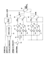
- FIG. 2 is a block diagram illustrating the configuration of the control device according to the first embodiment.
- the control device includes an acceleration / deceleration control device 11, an engine control device 6, a brake control device 7, a transmission control device 8, an engine 1, a brake 2, a transmission 3, and a clutch 5.
- an acceleration / deceleration control device 11 an engine control device 6, a brake control device 7, a transmission control device 8, an engine 1, a brake 2, a transmission 3, and a clutch 5.
- the acceleration / deceleration control device 11 determines the torque generated by the engine 1 based on the preceding vehicle detection signal output from the front recognition sensor 9, the vehicle speed signal output from the vehicle speed sensor 10, and the position signal output from the GPS sensor 12.
- a target torque signal that is a target value, a target rotational speed signal that is a target value of the rotational speed of the engine 1, and a target braking force signal that is a target value of the braking force generated by the brake 2 are calculated. Thereby, acceleration / deceleration of the vehicle can be controlled.
- the engine control device 6 calculates a fuel / air supply amount signal that commands the fuel / air supply amount to the engine 1 based on the target torque signal output by the acceleration / deceleration control device 11. As a result, the torque generated by the engine 1 can be controlled.
- the transmission control device 8 based on the target rotational speed signal output from the acceleration / deceleration control device 11, transmits a hydraulic pressure signal for instructing the hydraulic pressure to be supplied to the transmission 3, and a clutch hydraulic pressure for instructing the hydraulic pressure to be supplied to the clutch 5. Calculate the signal. Thereby, the gear ratio of the transmission 3, that is, the rotational speed of the engine 1 and the power transmission state of the clutch 5 can be controlled.
- the brake control device 7 calculates a brake hydraulic pressure signal that instructs the hydraulic pressure supplied to the brake 2 based on the target braking force signal output by the acceleration / deceleration control device 11. As a result, the braking force generated by the brake 2 can be controlled.
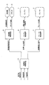
- FIG. 3 is a block diagram showing a configuration of the acceleration / deceleration control apparatus 11 in the first embodiment.
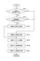
- FIG. 4 is a flowchart showing the operation of the acceleration / deceleration control apparatus 11 in the first embodiment.
- the acceleration / deceleration control operation of the first embodiment will be described below with reference to FIGS.
- the CPU of the acceleration / deceleration control device 11 constitutes the brake control block shown in FIG. 3 in the form of microcomputer software, and the brake control program shown in FIG. 4 is executed while the ignition key switch (not shown) of the vehicle is on. Run repeatedly.
- the acceleration / deceleration control device 11 is provided with a specific location information acquisition unit 20, a target braking / driving force calculation unit 21, a target engine torque calculation unit 22, a target brake braking force calculation unit 23, and a target engine speed calculation unit 24. Yes. The operation of each part will be described below.
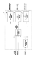
- FIG. 5 is a block diagram showing a configuration of the target braking / driving force calculation unit 21 in the first embodiment.
- the acceleration / deceleration control operation of the first embodiment will be described below with reference to FIG.
- step S001 the specific location information acquisition unit 20 collates the position signal input from the GPS sensor 12 with the map data provided in the memory of the acceleration / deceleration control device 11, and determines whether or not the vehicle exists at the specific location. And the determination result is output as a specific location signal (specific location information acquisition means). If it is determined as YES in step S001, the process proceeds to step S002. On the other hand, when it is determined NO in step S001, the mode determination unit 31 makes a transition to step S004.
- the specific location is determined based on the possibility of vehicle control related to acceleration or deceleration.
- the specific place is a place, position, or region (hereinafter referred to as a place) where the frequency of deceleration or acceleration is high as a traffic situation.
- Locations with high deceleration frequency as traffic conditions include, for example, traffic lights, railroad crossings, temporary stop positions, traffic intersections, places where road width decreases (locations where road width decreases), entrances to shopping streets where traffic volume is high, etc. Is mentioned.
- the acquisition of the specific location information has been described as an example in which the map data provided in the memory of the acceleration / deceleration control device 11 is collated. You may get it.
- step S002 the traffic condition determination unit 30 determines whether the inter-vehicle distance satisfies a predetermined condition from the preceding vehicle detection signal input from the forward recognition sensor 9. If it is determined in step S001 that the host vehicle is present at a specific location where the deceleration frequency is high, it is determined whether the inter-vehicle distance (inter-vehicle time) is within a preset first predetermined value, If it is within the first predetermined value, it is determined that the inter-vehicle distance (inter-vehicle time) satisfies a predetermined condition.
- step S001 when it determines with the own vehicle existing in the specific location with high acceleration frequency by step S001, it is judged whether the inter-vehicle distance (inter-vehicle time) is more than the 2nd predetermined value set beforehand, If the distance is greater than or equal to the second predetermined value, it is determined that the inter-vehicle distance (inter-vehicle time) satisfies a predetermined condition.
- the inter-vehicle distance is likely to become clogged (the inter-vehicle time is shortened). Therefore, by determining whether or not the inter-vehicle distance (inter-vehicle time) is within the first predetermined value, it can be determined whether or not the vehicle is likely to stop. Further, in a situation where acceleration is likely to occur due to an increase in the speed limit of the travel route or a change in the travel environment such as a curve exit, the inter-vehicle distance from the preceding vehicle is likely to increase (the inter-vehicle time becomes longer). Therefore, it is possible to determine whether or not acceleration is likely to occur by determining whether or not the inter-vehicle distance (inter-vehicle time) is equal to or greater than the second predetermined value.
- step S002 If it is determined YES in step S002, the mode determination unit 31 makes a transition to step S003. On the other hand, when it is determined NO in step S002, the mode determination unit 31 makes a transition to step S004.
- the target braking / driving force calculation unit 21 generates a target braking / driving force signal for the high response mode from the preceding vehicle detection signal input from the front recognition sensor 9 and the vehicle speed signal input from the vehicle speed sensor 10. Calculate and output as the final target braking / driving force signal.
- the inter-vehicle deviation calculation unit 32 calculates a difference between the target inter-vehicle distance provided in the memory of the acceleration / deceleration control device 11 and the inter-vehicle distance included in the preceding vehicle detection signal, and outputs the difference as an inter-vehicle distance deviation signal.
- the intervehicular deviation integrating unit 33 integrates the intervehicular distance deviation signals input from the intervehicular deviation calculating unit 32 and outputs an intervehicular distance deviation integrated signal.
- the proportional control amount obtained by multiplying the inter-vehicle distance deviation signal by a gain 35 and the inter-vehicle distance deviation integrated signal by a gain 36 are multiplied by a constant.
- the added control amount is added by the adder 37 and output as a target braking / driving force signal for the high response mode.
- the proportional control amount obtained by multiplying the inter-vehicle distance deviation signal by a gain 38 and the inter-vehicle distance deviation integrated signal by a gain 39 are multiplied by a constant.
- the added control amount is added by the adder 40 and output as a target braking / driving force signal for the high response mode.
- the target braking / driving force signal for the high response mode is a response from the target inter-vehicle distance and the inter-vehicle distance to the negative decrease side of the target braking / driving force signal, compared to the target braking / driving force signal for the fuel saving mode described later. Is a fast setting.
- the target braking / driving force signal changes quickly when decelerating when the vehicle is in a specific location and traffic conditions are congested and the vehicle is likely to stop.
- the car can be decelerated quickly.
- the target braking / driving force signal changes quickly during acceleration, so the vehicle is quickly accelerated to follow the accelerating preceding vehicle. Can be made.
- step S002 the traffic condition determination unit 30 determines whether the inter-vehicle distance is within a first predetermined value from the preceding vehicle detection signal input from the front recognition sensor 9, and this inter-vehicle distance is a moving average. A value smoothed with the above may be used.
- step S004 the target braking / driving force calculation unit 21 generates a target braking / driving force signal for the fuel saving mode from the preceding vehicle detection signal input from the front recognition sensor 9 and the vehicle speed signal input from the vehicle speed sensor 10. Calculate and output as the final target braking force signal.
- the fuel saving positive / negative switching unit 41 determines that the inter-vehicle distance deviation signal is negative, the proportional control amount obtained by multiplying the inter-vehicle distance deviation signal by a gain 42 and the inter-vehicle distance deviation integrated signal by a gain 43 are multiplied by a constant.
- the added control amount is added by the adder 44 and output as a target braking / driving force signal for the fuel saving mode.
- the proportional control amount obtained by multiplying the inter-vehicle distance deviation signal by a gain 46 and the inter-vehicle distance deviation integrated signal by a gain 47 are multiplied by a constant.
- the added control amount is added by the adder 45 and output as a target braking / driving force signal for the fuel saving mode.
- the target braking / driving force signal for the fuel saving mode has a slower response from the target inter-vehicle distance and the inter-vehicle distance to the negative value decreasing side of the target braking / driving force signal than the target braking / driving force signal for the high response mode. It is set. As a result, when the traffic situation is not congested, acceleration / deceleration is suppressed, the follow-up performance with respect to the preceding vehicle becomes slow, and fuel consumption can be improved.
- step S005 the target engine torque calculator 22 calculates a target torque signal.
- the target braking / driving force signal input from the acceleration / deceleration control device 11 is divided by the engine speed and limited to a positive value to obtain a target torque signal.
- step S006 the target engine speed calculator 24 calculates a target speed signal.
- the target braking / driving force signal input from the acceleration / deceleration control device 11 and the output of the engine 1 obtained by integrating the vehicle speed, the most efficient rotational speed is set as the target rotational speed signal.
- step S007 the target brake braking force calculation unit 23 calculates a target braking force signal.
- the target braking / driving force signal input from the acceleration / deceleration control device 11 is obtained.
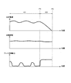
- FIG. 6 is a diagram for explaining the operation of the conventional ACC, and shows the preceding vehicle speed, the inter-vehicle time, and the brake control amount (positive during deceleration).
- the section I12 is a section from the signal P0 to the front position P1, and is a place where the deceleration frequency is higher than the section I11 as a traffic situation.
- the conventional ACC controls the engine 1 and the brake 2 so as to keep the inter-vehicle time constant. Therefore, as shown in the section I11, every time the speed of the preceding vehicle fluctuates, deceleration by the brake 2 occurs, leading to deterioration of fuel consumption. Note that, in the section I12, the brake braking force quickly rises according to the decrease in the vehicle speed of the preceding vehicle, so that the preceding vehicle is not excessively approached.
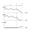
- FIG. 7 is a diagram for explaining the operation of the conventional ACC in which the response of acceleration / deceleration is suppressed, and shows the preceding vehicle speed, the inter-vehicle time, and the brake control amount (positive during deceleration).
- the section I22 is a section from the signal P0 to the front position P1, and is a place where the deceleration frequency is higher than the section I21 as a traffic situation.
- the acceleration / deceleration response is suppressed, as shown in the section I21, even if the speed of the preceding vehicle fluctuates, the frequency of deceleration by the brake 2 can be suppressed, and fuel efficiency can be improved.
- section I22 when the preceding vehicle stops with a signal or the like, the vehicle tends to approach the preceding vehicle with a delay in deceleration, leading to deterioration in drivability.
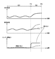
- FIG. 8 is a diagram for explaining the operation of the vehicle control apparatus according to the present embodiment, and explains the contents of control at a specific location with a high deceleration frequency.
- the preceding vehicle speed, inter-vehicle time, and brake control amount (positive during deceleration) are shown, respectively.
- the section I33 is a section from the signal P0 to the near position P1, and is a place (a specific place) where the deceleration frequency is higher than the section I31 as a traffic situation.
- the inter-vehicle time (inter-vehicle distance) with the preceding vehicle is within the first predetermined value.
- the vehicle control apparatus Since the vehicle control apparatus according to the present embodiment normally responds slowly to the negative value decrease side of the target braking / driving force signal even if the speed of the preceding vehicle fluctuates as shown in the section I31, the vehicle control apparatus decelerates by the brake 2. The frequency can be suppressed, and the fuel consumption can be improved.
- the target braking / driving The response of the force signal to the negative value decreasing side becomes faster, and the response of the braking / driving force when the braking force of the braking force source is increased can be increased. Therefore, the host vehicle can be decelerated without delay with respect to the preceding vehicle, the deterioration of drivability can be prevented, and the followability of the host vehicle can be improved.
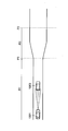
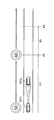
- FIG. 9 and FIG. 10 are diagrams for explaining the operation of the vehicle control device in the present embodiment, and are diagrams for explaining the contents of control at a specific location with a high acceleration frequency.
- FIG. 9 shows changes in the preceding vehicle speed, the inter-vehicle time, and the engine driving force.
- the section I52 is a section from a road width widening position P0 where the road width is widened to a predetermined position P2 on the front side in the traveling direction, and a traffic situation where the acceleration frequency is higher than the section I51 (specification Part).
- the preceding vehicle 1002 is more likely to be accelerated due to the road width being wider than in section I51.
- the response to the negative decrease side of the target braking / driving force signal is slow. Can be suppressed, and fuel consumption can be improved.
- the own vehicle 1001 passes through the road width widening position P0 and enters the specific section I52, the response to the negative side of the target braking / driving force signal becomes faster, and the driving force of the driving force source increases.
- the response of the braking / driving force at the time can be increased. Therefore, when the preceding vehicle 1002 accelerates in the section I52, it can be accelerated without delay from the preceding vehicle 1002, as shown by the solid line in FIG. Therefore, the followability of the own vehicle 1001 can be improved at a specific location, and deterioration of drivability can be prevented.
- FIG. 11 and FIG. 12 are diagrams illustrating an example of a specific location with a high acceleration frequency
- FIG. 13 is a diagram illustrating an example of a specific location with a high acceleration frequency and a specific location with a high deceleration frequency.
- the speed limit of the travel route is changed from 50 km / h to 60 km / h at a midway position on the road.
- the speed limit changing position P0 is defined between the speed limit changing position P0 and the predetermined position P2 on the front side in the traveling direction.
- the section I61 it becomes possible to suppress the acceleration frequency by the engine 1 of the own vehicle 1011 and to improve the fuel consumption. And in the section I62, the followability of the own vehicle 1011 can be improved, and deterioration of drivability can be prevented.
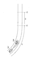
- FIG. 12 is a diagram showing the exit of the curve.
- acceleration of the preceding vehicle 1022 is likely to occur at the exit of the curve. Accordingly, a specific portion is defined between the curve exit P0 and the predetermined position P2 on the front side in the traveling direction.
- the section I71 it becomes possible to suppress the acceleration frequency by the engine 1 of the own vehicle 1021, and the fuel consumption can be improved.
- the followability of the own vehicle 1021 can be improved, and deterioration of drivability can be prevented.
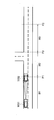
- FIG. 13 is a diagram illustrating a T-shaped intersection.
- deceleration is likely to occur as the traffic situation (first specific location)
- acceleration is likely to occur as the traffic situation ( Second specific part).
- the vehicle control apparatus according to the present embodiment has a slow response to the negative value decrease side of the target braking / driving force signal even if the speed of the preceding vehicle fluctuates. It is possible to suppress the acceleration frequency and improve fuel efficiency.
- the response to the negative value decrease side of the target braking / driving force signal is faster than the section I81, and the vehicle can be decelerated without delay. , Can prevent deterioration of drivability.
- the response to the negative value decrease side of the target braking / driving force signal becomes faster compared to the section I81, and without delay in the acceleration of the preceding vehicle. It is possible to follow, and the deterioration of drivability can be prevented.
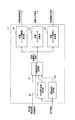
- FIG. 14 is a block diagram illustrating a configuration of the vehicle control device according to the second embodiment.
- a part of the configuration of the first embodiment described above is changed.
- the same elements as those shown in FIGS. 1 to 13 are denoted by the same reference numerals, and different points will be mainly described below.
- the acceleration / deceleration control calculation unit 11 in the second embodiment includes a specific location signal output by the specific location information acquisition unit 20, a speed limit signal acquired by the speed limit acquisition unit 100, and a preceding output output by the front recognition sensor 9. Based on the vehicle detection signal and the vehicle speed signal output from the vehicle speed sensor 10, a target braking / driving force signal of the braking / driving force calculating unit 21 is calculated.
- the speed limit acquisition unit 100 collates the position signal input from the GPS sensor 12 with the map data provided in the memory of the acceleration / deceleration control device 11, acquires the speed limit of the position of the host vehicle, and uses it as a speed limit signal. Output (speed limit acquisition means).
- FIG. 15 is a flowchart showing the operation of the acceleration / deceleration control apparatus 11 in the second embodiment.
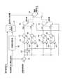
- FIG. 16 is a block diagram showing the configuration of the target braking / driving force calculation unit 21 in the second embodiment.
- the acceleration / deceleration control operation of the second embodiment will be described with reference to FIGS. 15 and 16.
- step S002 the traffic situation determination unit 30 determines that the preceding vehicle speed is lower than the speed limit based on the preceding vehicle detection signal input from the front recognition sensor 9 and the speed limit signal input from the speed limit acquisition unit 100. In addition, it is determined whether or not the difference between the speed limit and the preceding vehicle speed is greater than or equal to a predetermined value. In a situation where the traffic situation is congested and the vehicle is likely to stop, the speed tends to decrease with respect to the speed limit. Therefore, it is determined whether or not the vehicle is likely to stop by determining whether or not the preceding vehicle speed is lower than the speed limit and the difference between the speed limit and the preceding vehicle speed is greater than or equal to a predetermined value. be able to.
- step S002 when the preceding vehicle speed is lower than the speed limit by a predetermined value or more, YES is determined in step S002, and the mode determination unit 31 makes a transition to step S003. On the other hand, when it is determined NO in step S002, the mode determination unit 31 makes a transition to step S004.
- the target braking / driving force signal changes quickly when decelerating when the vehicle is in a specific location and traffic conditions are congested and the vehicle is likely to stop. You can slow down.
- the traffic condition determination unit 30 determines a difference between the speed limit and the preceding vehicle speed from the preceding vehicle detection signal input from the forward recognition sensor 9 and the speed limit signal input from the speed limit acquiring unit 100. Although it is determined whether or not the value is greater than or equal to the value, a value smoothed by a moving average or the like may be used as the difference between the speed limit and the preceding vehicle speed.
- FIG. 17 is a diagram for explaining the operation of the vehicle control device according to the present embodiment.
- the preceding vehicle speed, inter-vehicle time, and brake control amount (positive during deceleration) are shown, respectively.
- the section I43 is a section from the signal P0 to the front position P1, and is a place (a specific place) where the deceleration frequency is higher than that of the section I41 as a traffic situation.
- Section I42 and section I43 are sections in which the inter-vehicle time (inter-vehicle distance) with the preceding vehicle is within a predetermined value.
- the vehicle control apparatus normally decelerates by the brake 2 because the response to the negative value decrease side of the target braking / driving force signal is slow even when the speed of the preceding vehicle fluctuates as shown in the section I41.
- the frequency can be suppressed, and the fuel consumption can be improved.
- section I42 when the difference between the speed limit and the preceding vehicle speed is equal to or less than a predetermined value, and as shown in section I43, if the vehicle exists at a specific location, the target braking / driving force signal decreases to the negative value side.
- the response of the vehicle becomes faster and the vehicle can decelerate without delay with respect to the decrease in the speed of the preceding vehicle. Thereby, deterioration of drivability can be prevented.
- the present invention is not limited to the above-described embodiments, and various designs can be made without departing from the spirit of the present invention described in the claims. It can be changed.
- the above-described embodiment has been described in detail for easy understanding of the present invention, and is not necessarily limited to one having all the configurations described.
- a part of the configuration of an embodiment can be replaced with the configuration of another embodiment, and the configuration of another embodiment can be added to the configuration of an embodiment.
Landscapes
- Engineering & Computer Science (AREA)
- Transportation (AREA)
- Mechanical Engineering (AREA)
- Chemical & Material Sciences (AREA)
- Combustion & Propulsion (AREA)
- Automation & Control Theory (AREA)
- Physics & Mathematics (AREA)
- Mathematical Physics (AREA)
- Control Of Driving Devices And Active Controlling Of Vehicle (AREA)
- Controls For Constant Speed Travelling (AREA)
- Regulating Braking Force (AREA)
Abstract
本発明は、先行車との相対関係に基づいて自車の挙動を制御する状態において燃費を向上しかつ運転性の悪化を防ぐことができる車両制御装置を得る。本発明の車両制御装置は、先行車との相対関係に基づいて自車の挙動を制御するものであって、加速又は減速に関する車両制御の可能性に基づいて決定される特定箇所の情報を取得する特定箇所情報取得部(20)を備え、前記特定箇所では前記先行車に対する追従性を上昇させることを特徴とする。
Description
本発明は、車両制御装置に関するものである。
近年、カメラやレーダなどの前方認識センサを用いて先行車を認識して、先行車との車間距離を維持するように加減速を制御する車両制御装置が開発されている。
この車両制御装置は、先行車へ接近した場合においては、エンジンの出力を低下させる、もしくは摩擦ブレーキの油圧を高めることにより減速し、先行車との車間距離を広げる。また、先行車との車間距離が開いた場合や、自車の走行経路上から外れた場合には、エンジンの出力を増加させ、所定速度まで加速する。これにより、先行車へ衝突しないように車間距離を保ちつつ、周囲の車両に合わせて走行することができる。
また、車両制御装置において走行中の加減速を抑えることで、燃費を向上する技術が知られている。加減速を抑えることで、摩擦ブレーキによる損失を低減し、エンジンをより高効率な動作点で運転することが可能となり、車両の燃費を向上することができる。
特許文献1に記載の装置はその一例であり、自車がエコモードに設定されている場合には、通常モードよりも加速度を抑えて走行するようにしている。これにより、車両の燃費向上を図っている。
しかしながら、燃費向上を目的として、加減速を抑えると、先行車が信号等で停車した場合等に、自車の減速が遅れて先行車へ過剰に接近するため、運転性が悪化する、という問題があった。
本発明は、上記の点に鑑みてなされたものであり、その目的とするところは、先行車との相対関係に基づいて自車の挙動を制御する状態において燃費を向上しかつ運転性の悪化を防ぐことができる車両制御装置を提供することである。
上記課題を解決する本発明の車両制御装置は、先行車との相対関係に基づいて自車の挙動を制御する車両制御装置であって、加速又は減速に関する車両制御の可能性に基づいて決定される特定箇所(場所、位置、領域:location)の情報を取得する特定箇所情報取得手段を備え、前記特定箇所では前記先行車に対する追従性を上昇させる、ことを特徴とする。
本発明によれば、先行車との相対関係に基づいて自車の挙動を制御する状態において燃費を向上しかつ運転性の悪化を防ぐことができる。
本発明に関連する更なる特徴は、本明細書の記述、添付図面から明らかになるものである。また、上記した以外の、課題、構成及び効果は、以下の実施形態の説明により明らかにされる。
本発明に関連する更なる特徴は、本明細書の記述、添付図面から明らかになるものである。また、上記した以外の、課題、構成及び効果は、以下の実施形態の説明により明らかにされる。
以下、図を参照して本発明を実施するための形態について説明する。以下に説明する実施形態では、内燃機関であるエンジンを唯一の駆動源とする車両の自動運転装置に適用した場合を例に挙げて本発明を説明しているが、本発明は、エンジンと電動機とを車両の駆動源とする電動車両、例えばハイブリッド自動車(乗用車)、ハイブリッドトラックなどの貨物自動車、ハイブリッドバスなどの乗り合い自動車などの運転支援装置にも適用することができる。
(第1の実施の形態)
図1は、第1の実施の形態における車両制御装置の構成を示す図である。なお、図1の破線矢印は信号の流れを示している。
図1は、第1の実施の形態における車両制御装置の構成を示す図である。なお、図1の破線矢印は信号の流れを示している。
車両制御装置は、先行車との相対関係に基づいて自車の挙動を制御する。車両には、車両を駆動するエンジン1と、車両を制動させるブレーキ2(制動力源)と、エンジン1が発生した駆動力を無段階で変速する変速機3と、変速機3と駆動輪4の間で動力を伝達するクラッチ5と、エンジン1の燃焼状態を制御してエンジン1が発生させる動力を変化させるエンジン制御装置6と、ブレーキ2の油圧を制御してブレーキ2が発生させる制動力を変化させるブレーキ制御装置7と、変速機3の回転数を制御して変速比を変化させ、またクラッチ5の動力伝達を制御する変速機制御装置8と、車両前方の物体を検知する前方認識センサ9と、車両の速度を検出する車速センサ10と、エンジン制御装置6およびブレーキ制御装置7および変速機制御装置8へ動作を指令する加減速制御装置11と、自車の位置を検出するGPSセンサ12と、を備えている。
エンジン1が燃料を燃焼させることにより発生させた動力は、変速機3に伝えられ、この変速機3内部のベルト式の変速機構により変速された後に、クラッチ5および差動機構13を介して左右の駆動輪4に伝えられ、車両を駆動する駆動力となる。駆動輪4の近傍には車両の制動力を発生させるブレーキ2が設けられている。ブレーキ2には油圧倍力装置が備えられており、この油圧倍力装置が発生する油圧操作力で駆動輪4を押さえつけ、摩擦力を発生させる。これにより運動エネルギーを熱エネルギーに変換し、車両を制動させることができる。
図1において、加減速制御装置11はCPUやメモリなどから構成され、制御プログラムを実行して、エンジン制御装置6と、ブレーキ制御装置7と、変速機制御装置8と、への指令値を演算する。これにより、車両の加減速を制御することができる。
図1において、エンジン制御装置6はCPUやメモリなどから構成され、制御プログラムを実行してエンジン1の燃料供給量や空気供給量を演算する。これにより、エンジン1が発生する制駆動力を制御することができる。
図1において、ブレーキ制御装置7はCPUやメモリなどから構成され、制御プログラムを実行してブレーキ2の油圧を演算する。これにより、ブレーキ2が生じる制動力を制御することができる。
図1において、変速機制御装置8はCPUやメモリなどから構成され、制御プログラムを実行して変速機3とクラッチ5の油圧を演算する。これにより、変速機3の変速比およびクラッチ5の動力伝達を制御することができる。
図1に示すように、加減速制御装置11には、車両前方の物体を検知する前方認識センサ9、車両の速度を検出する車速センサ10、自車の位置を検出するGPSセンサ12などが接続されている。
前方認識センサ9は、車両前方を走行する先行車の、車間距離および相対速度を検出し、該検出した先行車検出情報を先行車検出信号として出力することができる(先行車検出手段)。
加減速制御装置11は、前方認識センサ9の先行車検出信号と、車速センサ10の速度信号とを用いて演算し、エンジン制御装置6と、ブレーキ制御装置7と、変速機制御装置8とに制駆動力を指令する。前方認識センサ9が検出した先行車との車間距離が縮まった場合には減速するように指令する。前方認識センサ9が検出した先行車と車間距離が離れた場合や、先行車がいなくなった場合には所定速度まで加速するように指令する。これにより、先行車へ接近しすぎることなく、周囲車両に合わせて走行制御することができる。
図2は、第1の実施の形態における制御装置の構成を示すブロック図である。制御装置には、加減速制御装置11、エンジン制御装置6、ブレーキ制御装置7、変速機制御装置8、エンジン1、ブレーキ2、変速機3、クラッチ5、が設けられている。以下では、図2を用いて第1の実施の形態における制御装置の演算の流れを説明する。
加減速制御装置11は、前方認識センサ9が出力する先行車検出信号と、車速センサ10が出力する車速信号と、GPSセンサ12が出力する位置信号と、に基づいて、エンジン1が発するトルクの目標値である目標トルク信号と、エンジン1の回転数の目標値である目標回転数信号と、ブレーキ2が発生する制動力の目標値である目標制動力信号を演算する。これにより車両の加減速を制御することができる。
エンジン制御装置6は、加減速制御装置11が出力する目標トルク信号に基づいて、エンジン1への燃料・空気の供給量を指令する燃料・空気供給量信号を演算する。これによりエンジン1が発生するトルクを制御することができる。
変速機制御装置8は、加減速制御装置11が出力する目標回転数信号に基づいて、変速機3へ供給する油圧を指令する変速機油圧信号と、クラッチ5へ供給する油圧を指令するクラッチ油圧信号とを演算する。これにより変速機3の変速比すなわちエンジン1の回転数と、クラッチ5の動力伝達状態を制御することができる。
ブレーキ制御装置7は、加減速制御装置11が出力する目標制動力信号に基づいて、ブレーキ2へ供給する油圧を指令するブレーキ油圧信号を演算する。これによりブレーキ2が発生する制動力を制御することができる。
図3は、第1の実施の形態における加減速制御装置11の構成を示すブロック図である。図4は第1の実施の形態における加減速制御装置11の動作を示すフローチャートである。以下では、図3、図4を用いて第1の実施の形態の加減速制御動作を説明する。加減速制御装置11のCPUは、マイクロコンピュータのソフトウェア形態により図3に示すブレーキ制御ブロックを構成し、車両のイグニッションキースイッチ(不図示)がオンしている間、図4に示すブレーキ制御プログラムを繰り返し実行する。
加減速制御装置11には、特定箇所情報取得部20、目標制駆動力演算部21、目標エンジントルク演算部22、目標ブレーキ制動力演算部23、目標エンジン回転数演算部24、が設けられている。各部の動作は以下に説明する。
図5は第1の実施の形態における目標制駆動力演算部21の構成を示すブロック図である。以下では、図5も合わせて用いて、第1の実施の形態の加減速制御動作を説明する。
ステップS001で、特定箇所情報取得部20は、GPSセンサ12から入力される位置信号と、加減速制御装置11のメモリ内に備えた地図データを照合し、自車が特定箇所に存在するか否かを判定し、その判定結果を特定箇所信号として出力する(特定箇所情報取得手段)。ステップS001においてYESと判定された場合には、ステップS002へ進む。一方、ステップS001においてNOと判定された場合には、モード判定部31がステップS004へ遷移させる。
特定箇所は、加速又は減速に関する車両制御の可能性に基づいて決定される。特定箇所とは、交通状況として減速頻度または加速頻度が高い場所、位置、領域(以下、場所等)である。交通状況として減速頻度が高い場所等としては、例えば、信号、踏切、一時停止位置、交通量の多い交差点、道路幅が減少する場所(道路幅減少箇所)、交通量の多い商店街の入口等が挙げられる。そして、交通状況として加速頻度が高い場所等としては、例えば、道路幅が拡大する箇所、制限速度が上昇する地点、カーブ出口、高頻度で減速する場所よりも先の場所(例えば、交差点や信号の先)等が挙げられる。本実施の形態では、特定箇所情報の取得は、加減速制御装置11のメモリ内に備えた地図データを照合した場合を例に説明したが、路車間通信等の技術を用いて、外部データベースから取得してもよい。
ステップS002で、交通状況判定部30は、前方認識センサ9から入力される先行車検出信号から、車間距離が所定条件を満たすか否かを判定する。ステップS001で自車が減速頻度の高い特定箇所に存在していると判定された場合には車間距離(車間時間)が予め設定された第1の所定値以内であるか否かが判断され、第1の所定値以内の場合には車間距離(車間時間)が所定条件を満たすと判定される。そして、ステップS001で自車が加速頻度の高い特定箇所に存在していると判定された場合には車間距離(車間時間)が予め設定された第2の所定値以上か否かが判断され、第2の所定値以上の場合には車間距離(車間時間)が所定条件を満たすと判定される。
交通状況が混雑して停車が発生し易い状況では、車間距離が詰りやすくなる(車間時間が短くなる)。そのため、車間距離(車間時間)が第1の所定値以内であるか否かを判定することにより、停車が発生し易い状況であるか否かを判定することができる。また、走行経路の制限速度の上昇やカーブ出口などの走行環境の変化等によって加速が発生し易い状況では、先行車との間の車間距離が広がりやすくなる(車間時間が長くなる)。そのため、車間距離(車間時間)が第2の所定値以上であるか否かを判定することにより、加速が発生し易い状況であるか否かを判定することができる。
ステップS002においてYESと判定された場合には、モード判定部31がステップS003へ遷移させる。一方、ステップS002においてNOと判定された場合には、モード判定部31がステップS004へ遷移させる。
ステップS003で、目標制駆動力演算部21は、前方認識センサ9から入力される先行車検出信号と、車速センサ10から入力される車速信号とから、高応答モード用の目標制駆動力信号を演算し、最終的な目標制駆動力信号として出力する。車間偏差演算部32は、加減速制御装置11のメモリ内に備えた目標車間距離と先行車検出信号に含まれる車間距離との差を演算し、車間距離偏差信号として出力する。車間偏差積算部33は、車間偏差演算部32から入力される車間距離偏差信号を積算し車間距離偏差積算信号を出力する。
車間距離偏差信号が負であると高応答時正負切換え部34が判定した場合には、車間距離偏差信号をゲイン35で定数倍した比例制御量と、車間距離偏差積算信号をゲイン36で定数倍した積算制御量と、を加算器37で加算し、高応答モード用の目標制駆動力信号として出力する。
車間距離偏差信号が正であると高応答時正負切換え部34が判定した場合には、車間距離偏差信号をゲイン38で定数倍した比例制御量と、車間距離偏差積算信号をゲイン39で定数倍した積算制御量と、を加算器40で加算し、高応答モード用の目標制駆動力信号として出力する。
高応答モード用の目標制駆動力信号は、後述する省燃費モード用の目標制駆動力信号と比較して、目標車間距離と車間距離から、目標制駆動力信号の負値減少側への応答が速い設定となっている。
これにより、自車が特定箇所に存在しかつ交通状況が混雑して停車が発生し易い状況の場合は、減速時に目標制駆動力信号が素早く変化するため、停車する先行車に対して、自車を素早く減速させることができる。また、自車が特定箇所に存在しかつ加速が発生し易い状況の場合は、加速時に目標制駆動力信号が素早く変化するため、加速する先行車に対して、自車を素早く加速させて追従させることができる。
混雑して停車が発生し易い状況であるか否か等の交通状況は,比較的緩やかに変化する。ステップS002で、交通状況判定部30は、前方認識センサ9から入力される先行車検出信号から、車間距離が第1の所定値以内であるか否かを判定するが、この車間距離は移動平均等で平滑化した値を用いてもよい。
ステップS004で、目標制駆動力演算部21は、前方認識センサ9から入力される先行車検出信号と、車速センサ10から入力される車速信号とから、省燃費モード用の目標制駆動力信号を演算し、最終的な目標制動力信号として出力する。
車間距離偏差信号が負であると省燃費時正負切換え部41が判定した場合には、車間距離偏差信号をゲイン42で定数倍した比例制御量と、車間距離偏差積算信号をゲイン43で定数倍した積算制御量と、を加算器44で加算し、省燃費モード用の目標制駆動力信号として出力する。
車間距離偏差信号が正であると省燃費時正負切換え部41が判定した場合には、車間距離偏差信号をゲイン46で定数倍した比例制御量と、車間距離偏差積算信号をゲイン47で定数倍した積算制御量と、を加算器45で加算し、省燃費モード用の目標制駆動力信号として出力する。
省燃費モード用の目標制駆動力信号は、高応答モード用の目標制駆動力信号と比較して、目標車間距離と車間距離から、目標制駆動力信号の負値減少側への応答が遅い設定となっている。これにより、交通状況が混雑していない場合には、加減速が抑えられて先行車に対する追従性が緩慢となり、燃費を向上させることができる。
ステップS005で、目標エンジントルク演算部22は、目標トルク信号を演算する。
加減速制御装置11から入力される目標制駆動力信号をエンジン回転数で除算して、正値へ制限することで、目標トルク信号とする。
加減速制御装置11から入力される目標制駆動力信号をエンジン回転数で除算して、正値へ制限することで、目標トルク信号とする。
ステップS006で、目標エンジン回転数演算部24は、目標回転数信号を演算する。
加減速制御装置11から入力される目標制駆動力信号と、車速を積算して得たエンジン1の出力に対して、最も効率が良い回転数を目標回転数信号とする。
加減速制御装置11から入力される目標制駆動力信号と、車速を積算して得たエンジン1の出力に対して、最も効率が良い回転数を目標回転数信号とする。
ステップS007で、目標ブレーキ制動力演算部23は、目標制動力信号を演算する。
加減速制御装置11から入力される目標制駆動力信号を、負値へ制限することで、目標制動力信号とする。
加減速制御装置11から入力される目標制駆動力信号を、負値へ制限することで、目標制動力信号とする。
図6は従来のACCの動作を説明する図であり、それぞれ先行車速度、車間時間、ブレーキ制御量(減速時に正)を示している。区間I12は、信号P0から手前位置P1までの区間であり、交通状況として区間I11よりも減速頻度が高い場所である。従来のACCは車間時間を一定に保つように、エンジン1やブレーキ2を制御する。そのため、区間I11に示す通り、先行車の速度が変動する度に、ブレーキ2による減速が発生し、燃費の悪化につながる。なお、区間I12では、先行車の車速の低下に応じてブレーキ制動力が早急に立ち上がるため、先行車に過剰に接近することはない。
図7は加減速の応答を抑えた従来のACCの動作を説明する図であり、それぞれ先行車速度、車間時間、ブレーキ制御量(減速時に正)を示している。区間I22は、信号P0から手前位置P1までの区間であり、交通状況として区間I21よりも減速頻度が高い場所である。加減速の応答を抑えると、区間I21に示す通り、先行車の速度が変動しても、ブレーキ2による減速頻度を抑えることが可能となり、燃費を向上できる。一方で、区間I22に示す通り、先行車が信号等で停車する場合には、減速が遅れて先行車へ接近しがちとなり、運転性の悪化につながる。
図8は、本実施の形態における車両制御装置の動作を説明する図であり、減速頻度の高い特定箇所における制御の内容を説明するものである。それぞれ先行車速度、車間時間、ブレーキ制御量(減速時に正)を示している。区間I33は、信号P0から手前位置P1までの区間であり、交通状況として区間I31よりも減速頻度が高い場所(特定箇所)である。区間I32と区間I33では、先行車との車間時間(車間距離)が第1の所定値以内となっている。
本実施の形態における車両制御装置は、通常時は区間I31に示す通り、先行車の速度が変動しても、目標制駆動力信号の負値減少側への応答が遅いため、ブレーキ2による減速頻度を抑えることが可能となり、燃費を向上できる。
一方で、区間I32に示す通り、車間時間(車間距離)が第1の所定値以内となり、さらに区間I33に示す通り、信号P0の近傍に至り、自車が特定箇所に入ると、目標制駆動力信号の負値減少側への応答が速くなり、制動力源の制動力増時の制駆動力の応答性を上昇させることができる。したがって、先行車に対して自車を遅れず減速させることができ、運転性の悪化を防ぎ、自車の追従性を向上させることができる。
図9及び図10は、本実施の形態における車両制御装置の動作を説明する図であり、加速頻度の高い特定箇所における制御の内容を説明する図である。図9には、先行車速度、車間時間、エンジン駆動力の変化を示している。区間I52は、図10に示すように、途中で道路幅が広がる道路幅拡大位置P0から進行方向前側の所定位置P2までの区間であり、交通状況として区間I51よりも加速頻度が高い場所(特定箇所)である。区間I52では、区間I51よりも道路幅が広がることによって先行車1002の加速が発生し易い。
本実施の形態における車両制御装置は、区間I51では先行車1002の速度が変動しても、目標制駆動力信号の負値減少側への応答が遅いため、自車1001のエンジン1による加速頻度を抑えることが可能となり、燃費を向上できる。
一方で、自車1001が道路幅拡大位置P0を通過して特定箇所である区間I52に入ると、目標制駆動力信号の負値減少側への応答が速くなり、駆動力源の駆動力増時の制駆動力の応答性を上昇させることができる。したがって、区間I52で先行車1002が加速した場合に、図9に実線で示すように、先行車1002から遅れず加速することができ、車間距離が広がるのを防ぐことができる。したがって、特定箇所で自車1001の追従性を向上させることができ、運転性の悪化を防ぐことができる。
図11及び図12は、加速頻度の高い特定箇所の一例、図13は、加速頻度が高い特定箇所と減速頻度が高い特定箇所の一例を示す図である。
図11に示す例では、道路の途中位置で走行経路の制限速度が50km/hから60km/hに変わっている。図11に示すように、道路の途中位置で制限速度が変わると、先行車1012の加速が発生し易い。したがって、かかる制限速度変更位置P0から進行方向前側の所定位置P2までの間を特定箇所としている。これにより、区間I61では、自車1011のエンジン1による加速頻度を抑えることが可能となり、燃費を向上できる。
そして、区間I62では、自車1011の追従性を向上させることができ、運転性の悪化を防ぐことができる。
図11に示す例では、道路の途中位置で走行経路の制限速度が50km/hから60km/hに変わっている。図11に示すように、道路の途中位置で制限速度が変わると、先行車1012の加速が発生し易い。したがって、かかる制限速度変更位置P0から進行方向前側の所定位置P2までの間を特定箇所としている。これにより、区間I61では、自車1011のエンジン1による加速頻度を抑えることが可能となり、燃費を向上できる。
そして、区間I62では、自車1011の追従性を向上させることができ、運転性の悪化を防ぐことができる。
図12は、カーブの出口を示す図である。図12に示すように、カーブの出口では、先行車1022の加速が発生し易い。したがって、かかるカーブ出口P0から進行方向前側の所定位置P2までの間を特定箇所としている。これにより、区間I71では、自車1021のエンジン1による加速頻度を抑えることが可能となり、燃費を向上できる。そして、区間I72では、自車1021の追従性を向上させることができ、運転性の悪化を防ぐことができる。
図13は、T字の交差点を示す図である。図13に示すように、交差点の手前の区間I82は、交通状況として減速が発生し易く(第1の特定箇所)、交差点を通過した直後の区間I83は、交通状況として加速が発生し易い(第2の特定箇所)。
本実施の形態における車両制御装置は、区間I81では、先行車の速度が変動しても、目標制駆動力信号の負値減少側への応答が遅いため、ブレーキ2による減速頻度及びエンジン1による加速頻度を抑えることが可能となり、燃費を向上できる。
本実施の形態における車両制御装置は、区間I81では、先行車の速度が変動しても、目標制駆動力信号の負値減少側への応答が遅いため、ブレーキ2による減速頻度及びエンジン1による加速頻度を抑えることが可能となり、燃費を向上できる。
一方で、区間I82では、車間距離が第1の所定値以内の場合に、区間I81と比較して目標制駆動力信号の負値減少側への応答が速くなり、遅れず減速することができ、運転性の悪化を防ぐことができる。また、区間I83では、車間距離が第2の所定値以上の場合に、区間I81と比較して目標制駆動力信号の負値減少側への応答が速くなり、先行車の加速に遅れずに追従することができ、運転性の悪化を防ぐことができる。
(第2の実施の形態)
図14は、第2の実施の形態における車両制御装置の構成を示すブロック図である。第2の実施の形態では、上述した第1の実施の形態の一部の構成(加減速制御装置11の演算内容)を変更したものである。図1から図13に示す要素と同一の要素に対しては同一の符号を付し、以下では相違点を中心に説明する。
図14は、第2の実施の形態における車両制御装置の構成を示すブロック図である。第2の実施の形態では、上述した第1の実施の形態の一部の構成(加減速制御装置11の演算内容)を変更したものである。図1から図13に示す要素と同一の要素に対しては同一の符号を付し、以下では相違点を中心に説明する。
第2の実施の形態における加減速制御演算部11は、特定箇所情報取得部20が出力する特定箇所信号と、制限速度取得部100が取得する制限速度信号と、前方認識センサ9が出力する先行車検出信号と、車速センサ10が出力する車速信号に基づいて制駆動力演算部21の目標制駆動力信号を演算する。制限速度取得部100は、GPSセンサ12から入力される位置信号と、加減速制御装置11のメモリ内に備えた地図データを照合し、自車の位置の制限速度を取得し、制限速度信号として出力する(制限速度取得手段)。
図15は第2の実施の形態における加減速制御装置11の動作を示すフローチャートである。図16は第2の実施の形態における目標制駆動力演算部21の構成を示すブロック図である。以下では、図15、図16を用いて第2の実施の形態の加減速制御動作を説明する。
ステップS002で、交通状況判定部30は、前方認識センサ9から入力される先行車検出信号と、制限速度取得部100から入力される制限速度信号に基づいて、先行車速度が制限速度よりも低くかつ制限速度と先行車速度との差が所定値以上か否かを判定する。
交通状況が混雑して停車が発生し易い状況では、制限速度に対して速度が低下しやすくなる。そのため、先行車速度が制限速度よりも低くかつ制限速度と先行車速度との差が所定値以上であるか否かを判定することにより、停車が発生し易い状況であるか否かを判定することができる。例えば、先行車速度が制限速度よりも所定値以上低い場合には、ステップS002においてYESと判定され、モード判定部31がステップS003へ遷移させる。一方、ステップS002においてNOと判定された場合には、モード判定部31がステップS004へ遷移させる。
交通状況が混雑して停車が発生し易い状況では、制限速度に対して速度が低下しやすくなる。そのため、先行車速度が制限速度よりも低くかつ制限速度と先行車速度との差が所定値以上であるか否かを判定することにより、停車が発生し易い状況であるか否かを判定することができる。例えば、先行車速度が制限速度よりも所定値以上低い場合には、ステップS002においてYESと判定され、モード判定部31がステップS003へ遷移させる。一方、ステップS002においてNOと判定された場合には、モード判定部31がステップS004へ遷移させる。
これにより、自車が特定箇所に存在しかつ交通状況が混雑して停車が発生し易い状況の場合は、減速時に目標制駆動力信号が素早く変化するため、停車する先行車に対して、素早く減速することができる。
混雑して停車が発生し易い状況であるか否か等の交通状況は,比較的緩やかに変化する。ステップS002で、交通状況判定部30は、前方認識センサ9から入力される先行車検出信号と、制限速度取得部100から入力される制限速度信号と、から制限速度と先行車速度の差が所定値以上であるか否かを判定するが、この制限速度と先行車速度の差は移動平均等で平滑化した値を用いてもよい。
図17は本実施の形態における車両制御装置の動作を説明する図である。それぞれ先行車速度、車間時間、ブレーキ制御量(減速時に正)を示している。区間I43は、信号P0から手前位置P1までの区間であり、交通状況として区間I41よりも減速頻度が高い場所(特定箇所)である。区間I42と区間I43は、先行車との車間時間(車間距離)が所定値以内となる区間である。
本実施の形態における車両制御装置は、通常時は区間I41に示す通り、先行車の速度が変動しても、目標制駆動力信号の負値減少側への応答が遅いため、ブレーキ2による減速頻度を抑えることが可能となり、燃費を向上できる。一方で、区間I42に示す通り、制限速度と先行車速度の差が所定値以下となり、さらに区間I43に示す通り、自車が特定箇所に存在すると、目標制駆動力信号の負値減少側への応答が速くなり、先行車速度の低下に対して遅れず減速することができる。これにより運転性の悪化を防止することができる。
以上、本発明の実施形態について詳述したが、本発明は、前記の実施形態に限定されるものではなく、特許請求の範囲に記載された本発明の精神を逸脱しない範囲で、種々の設計変更を行うことができるものである。例えば、前記した実施の形態は本発明を分かりやすく説明するために詳細に説明したものであり、必ずしも説明した全ての構成を備えるものに限定されるものではない。また、ある実施形態の構成の一部を他の実施形態の構成に置き換えることが可能であり、また、ある実施形態の構成に他の実施形態の構成を加えることも可能である。さらに、各実施形態の構成の一部について、他の構成の追加・削除・置換をすることが可能である。
1:エンジン、2:ブレーキ、3:変速機、4:駆動輪、5:クラッチ、6:エンジン制御装置、7:ブレーキ制御装置、8:変速機制御装置、9:前方認識センサ、10:車速センサ、11:加減速制御装置、12:GPSセンサ、13:差動機構、20:特定箇所情報取得部、21:目標制駆動力演算部、22:目標エンジントルク演算部、23:目標ブレーキ制動力演算部、24:目標エンジン回転数演算部、30:交通状況判定部、31:モード判定部、32:車間偏差演算部、33:車間偏差積算部、34:高応答時正負切換え部、41:省燃費時正負切換え部、100:制限速度取得部
Claims (10)
- 先行車との相対関係に基づいて自車の挙動を制御する車両制御装置であって、
加速又は減速に関する車両制御の可能性に基づいて決定される特定箇所の情報を取得する特定箇所情報取得手段を備え、
前記特定箇所では前記先行車に対する追従性を上昇させる、ことを特徴とする車両制御装置。 - 先行車検出情報を出力する先行車検出手段を備え、
前記特定箇所の情報と前記先行車検出情報とに基づいて、前記先行車に対する追従性を上昇させる、ことを特徴とする請求項1に記載の車両制御装置。 - 前記特定箇所の情報と前記先行車検出情報とに基づいて、前記自車の制駆動力の応答性を上昇させる、ことを特徴とする請求項2に記載の車両制御装置。
- 前記先行車検出情報は前記先行車との車間距離または車間時間であり、前記自車が前記特定箇所に存在しかつ前記車間距離または車間時間が所定条件を満たす場合に、前記自車の制駆動力の応答性を上昇させる、ことを特徴とする請求項3に記載の車両制御装置。
- 前記特定箇所は、交通状況として減速頻度が高い場所であり、
前記自車が前記特定箇所に存在しかつ前記車間距離または車間時間が第1の所定値以内である場合に、前記自車の制駆動力の応答性を上昇させる、ことを特徴とする請求項4に記載の車両制御装置。 - 前記特定箇所は、交通状況として加速頻度が高い場所であり、
前記自車が前記特定箇所に存在しかつ前記車間距離または車間時間が第2の所定値以上である場合に、前記自車の制駆動力の応答性を上昇させる、ことを特徴とする請求項4又は請求項5に記載の車両制御装置。 - 走行経路の制限速度を取得する制限速度取得手段を備え、
前記先行車検出情報は先行車速度であり、前記自車が前記特定箇所に存在しかつ前記制限速度と前記先行車速度の差が所定値以上の場合に、前記自車の制駆動力の応答性を上昇させる、ことを特徴とする請求項4から請求項6のいずれか一項に記載の車両制御装置。 - 前記自車を制動させる制動力源を備え、
前記特定箇所の情報と前記先行車検出情報とに基づいて、前記制動力源の制動力の応答性を上昇させる、ことを特徴とする請求項4から請求項7のいずれか一項に記載の車両制御装置。 - 前記特定箇所の情報と前記先行車検出情報とに基づいて、前記制動力源の制動力増加時の制駆動力の応答性を上昇させる、ことを特徴とする請求項8に記載の車両制御装置。
- 前記特定箇所は、信号、踏切、一時停止位置、交差点、道路幅減少箇所、商店街の入口のいずれか一つを含む、ことを特徴とする請求項1から請求項9のいずれか一項に記載の車両制御装置。
Applications Claiming Priority (2)
| Application Number | Priority Date | Filing Date | Title |
|---|---|---|---|
| JP2016153802A JP6933452B2 (ja) | 2016-08-04 | 2016-08-04 | 車両制御装置 |
| JP2016-153802 | 2016-08-04 |
Publications (1)
| Publication Number | Publication Date |
|---|---|
| WO2018025631A1 true WO2018025631A1 (ja) | 2018-02-08 |
Family
ID=61074072
Family Applications (1)
| Application Number | Title | Priority Date | Filing Date |
|---|---|---|---|
| PCT/JP2017/026029 Ceased WO2018025631A1 (ja) | 2016-08-04 | 2017-07-19 | 車両制御装置 |
Country Status (2)
| Country | Link |
|---|---|
| JP (1) | JP6933452B2 (ja) |
| WO (1) | WO2018025631A1 (ja) |
Families Citing this family (2)
| Publication number | Priority date | Publication date | Assignee | Title |
|---|---|---|---|---|
| KR102178992B1 (ko) * | 2018-12-21 | 2020-11-17 | 충북대학교 산학협력단 | 차량 동작 계획방법 및 그를 위한 장치 |
| KR20250139594A (ko) * | 2024-03-15 | 2025-09-23 | 현대자동차주식회사 | 차량 제어 시스템 및 방법, 및 이를 포함하는 차량 |
Citations (2)
| Publication number | Priority date | Publication date | Assignee | Title |
|---|---|---|---|---|
| JP2002225589A (ja) * | 2001-02-02 | 2002-08-14 | Nissan Motor Co Ltd | 車両用走行制御装置 |
| JP2007168502A (ja) * | 2005-12-20 | 2007-07-05 | Nissan Motor Co Ltd | ハイブリッド車両の車間制御装置 |
Family Cites Families (1)
| Publication number | Priority date | Publication date | Assignee | Title |
|---|---|---|---|---|
| JP2012254754A (ja) * | 2011-06-10 | 2012-12-27 | Nissan Motor Co Ltd | 走行制御装置 |
-
2016
- 2016-08-04 JP JP2016153802A patent/JP6933452B2/ja not_active Expired - Fee Related
-
2017
- 2017-07-19 WO PCT/JP2017/026029 patent/WO2018025631A1/ja not_active Ceased
Patent Citations (2)
| Publication number | Priority date | Publication date | Assignee | Title |
|---|---|---|---|---|
| JP2002225589A (ja) * | 2001-02-02 | 2002-08-14 | Nissan Motor Co Ltd | 車両用走行制御装置 |
| JP2007168502A (ja) * | 2005-12-20 | 2007-07-05 | Nissan Motor Co Ltd | ハイブリッド車両の車間制御装置 |
Also Published As
| Publication number | Publication date |
|---|---|
| JP6933452B2 (ja) | 2021-09-08 |
| JP2018020687A (ja) | 2018-02-08 |
Similar Documents
| Publication | Publication Date | Title |
|---|---|---|
| JP4712830B2 (ja) | 車両制御装置 | |
| JP6988908B2 (ja) | 自動運転車両の制御方法および制御装置 | |
| JP6286192B2 (ja) | 移動体の駆動制御装置 | |
| JP6157412B2 (ja) | 車両用走行制御装置 | |
| JP6553469B2 (ja) | 車両制御装置 | |
| WO2019008647A1 (ja) | 運転支援車両の目標車速生成方法及び目標車速生成装置 | |
| CN108657177A (zh) | 车辆控制装置 | |
| CN114475562B (zh) | 一种拥堵坡道车辆跟车行驶的制动辅助控制方法和系统 | |
| JP2013248925A (ja) | 車両制御装置 | |
| JP6793759B2 (ja) | 自動車の走行制御装置、及び自動車の走行制御システム | |
| JPWO2013046301A1 (ja) | 車両の運転支援システム | |
| WO2019082361A1 (ja) | 自動運転車両の制御方法および制御装置 | |
| US20240270220A1 (en) | Method for Controlling a Braking Torque of a Vehicle During an at Least Partly Automated Traversal of an Incline And/or a Decline, Computing Device, and Assistance System for a Vehicle | |
| JP6760897B2 (ja) | 車両制御装置、車両制御方法、及び車両 | |
| CN111542464A (zh) | 车辆控制方法及车辆控制装置 | |
| JP6933452B2 (ja) | 車両制御装置 | |
| JP7825524B2 (ja) | 車両の接近の制御方法、間隔調節器、コンピュータプログラム、およびメモリユニット | |
| JP6253646B2 (ja) | 車両制御装置 | |
| JP6313834B2 (ja) | 車両制御装置 | |
| JP7294185B2 (ja) | 運転支援方法及び運転支援装置 | |
| CN115339444B (zh) | 自适应低速巡航控制方法、系统、设备及存储介质 | |
| CN115534951A (zh) | 控制车辆接近的方法、间距调节器、程序产品和存储单元 | |
| JP4797466B2 (ja) | 先行車追従制御装置 | |
| JP4692555B2 (ja) | 車両用追従走行制御装置 | |
| KR20080024648A (ko) | 차량의 자동 정지 및 출발 시스템 |
Legal Events
| Date | Code | Title | Description |
|---|---|---|---|
| 121 | Ep: the epo has been informed by wipo that ep was designated in this application |
Ref document number: 17836737 Country of ref document: EP Kind code of ref document: A1 |
|
| NENP | Non-entry into the national phase |
Ref country code: DE |
|
| 122 | Ep: pct application non-entry in european phase |
Ref document number: 17836737 Country of ref document: EP Kind code of ref document: A1 |