WO2018025459A1 - 内面電子線照射装置およびこれを具備する電子線滅菌設備 - Google Patents
内面電子線照射装置およびこれを具備する電子線滅菌設備 Download PDFInfo
- Publication number
- WO2018025459A1 WO2018025459A1 PCT/JP2017/016490 JP2017016490W WO2018025459A1 WO 2018025459 A1 WO2018025459 A1 WO 2018025459A1 JP 2017016490 W JP2017016490 W JP 2017016490W WO 2018025459 A1 WO2018025459 A1 WO 2018025459A1
- Authority
- WO
- WIPO (PCT)
- Prior art keywords
- electron beam
- beam irradiation
- nozzle
- nozzle body
- inert gas
- Prior art date
- Legal status (The legal status is an assumption and is not a legal conclusion. Google has not performed a legal analysis and makes no representation as to the accuracy of the status listed.)
- Ceased
Links
Images




Classifications
-
- A—HUMAN NECESSITIES
- A61—MEDICAL OR VETERINARY SCIENCE; HYGIENE
- A61L—METHODS OR APPARATUS FOR STERILISING MATERIALS OR OBJECTS IN GENERAL; DISINFECTION, STERILISATION OR DEODORISATION OF AIR; CHEMICAL ASPECTS OF BANDAGES, DRESSINGS, ABSORBENT PADS OR SURGICAL ARTICLES; MATERIALS FOR BANDAGES, DRESSINGS, ABSORBENT PADS OR SURGICAL ARTICLES
- A61L2/00—Disinfection or sterilisation of materials or objects, in general; Accessories therefor
- A61L2/02—Disinfection or sterilisation of materials or objects, in general; Accessories therefor using physical processes
- A61L2/08—Radiation
-
- G—PHYSICS
- G21—NUCLEAR PHYSICS; NUCLEAR ENGINEERING
- G21K—HANDLING OF PARTICLES OR IONISING RADIATION NOT OTHERWISE PROVIDED FOR; IRRADIATION DEVICES; GAMMA RAY OR X-RAY MICROSCOPES
- G21K5/00—Irradiation devices
-
- G—PHYSICS
- G21—NUCLEAR PHYSICS; NUCLEAR ENGINEERING
- G21K—HANDLING OF PARTICLES OR IONISING RADIATION NOT OTHERWISE PROVIDED FOR; IRRADIATION DEVICES; GAMMA RAY OR X-RAY MICROSCOPES
- G21K5/00—Irradiation devices
- G21K5/04—Irradiation devices with beam-forming means
-
- G—PHYSICS
- G21—NUCLEAR PHYSICS; NUCLEAR ENGINEERING
- G21K—HANDLING OF PARTICLES OR IONISING RADIATION NOT OTHERWISE PROVIDED FOR; IRRADIATION DEVICES; GAMMA RAY OR X-RAY MICROSCOPES
- G21K5/00—Irradiation devices
- G21K5/10—Irradiation devices with provision for relative movement of beam source and object to be irradiated
Definitions
- the present invention relates to an inner surface electron beam irradiation apparatus for sterilizing the inner surface of an object to be sterilized such as a container by electron beam irradiation, and an electron beam sterilization facility including the inner surface electron beam irradiation device.
- equipment that irradiates a container with an electron beam is used as a facility for surely sterilizing the container.
- an outer surface electron beam irradiation device that irradiates the outer surface of the container with an electron beam and an inner surface electron beam irradiation device that irradiates the inner surface of the container with an electron beam And are provided.
- the container when the container is irradiated with an electron beam, the container is surely sterilized, but corrosive gases such as ozone (O 3 ) and nitric acid (HNO 3 ) are generated by a chemical reaction by the electron beam.
- a ventilator for promoting the discharge of the corrosive gas is also provided in the equipment.
- the inner surface electron beam irradiation apparatus irradiates the inner surface of the container with an electron beam from the exit window of the electron beam irradiation nozzle while inserting the electron beam irradiation nozzle into the container from the opening. Since the corrosive gas tends to remain inside the container even when the ventilator is operated, the electron beam irradiation nozzle is exposed to the corrosive gas. For this reason, the electron beam irradiation nozzle is more easily corroded than other devices and equipment of the facility. In order to prevent such corrosion, it is conceivable to apply a conventional technique (see, for example, Patent Document 1) to cover the emission window of the electron beam irradiation nozzle with a catalyst film.
- an object of this invention is to provide the inner surface electron beam irradiation apparatus which can lengthen a lifetime, and the electron beam sterilization equipment provided with the same.
- an inner surface electron beam irradiation apparatus is an inner surface electron beam irradiation apparatus that sterilizes an inner surface of an object to be sterilized with an opening formed by electron beam irradiation,
- An electron beam irradiation nozzle that irradiates the inner surface of the object to be sterilized with an electron beam is provided,
- the electron beam irradiation nozzle has an emission window that emits an electron beam, a nozzle body that holds the emission window, and a protection unit that protects the nozzle body.
- a drive unit is provided for bringing the opening of the sterilization object and the exit window of the electron beam irradiation nozzle closer to and away from each other, and for bringing the sterilization object to be irradiated with an electron beam on the inner surface during the approach. It is a thing.
- the inner surface electron beam irradiation apparatus according to the second invention has a cap body in which the protection part in the inner surface electron beam irradiation apparatus according to the first invention is provided at the tip of the nozzle body.
- the protection part in the inner surface electron beam irradiation apparatus according to the first or second invention has a coating on the nozzle body.
- the inner surface electron beam irradiation apparatus includes an inert gas supply device in which the protection unit in the inner surface electron beam irradiation apparatus according to the first or second invention supplies an inert gas to the nozzle body. And an inert gas guide that guides the inert gas supplied by the inert gas feeder and discharges it from the tip of the nozzle body.
- the electron beam sterilization facility comprises an inner surface electron beam irradiation device according to the first or second invention, A transport device for transporting an object to be sterilized to the inner surface electron beam irradiation device; And an outer surface electron beam irradiation device that sterilizes the outer surface of the object to be sterilized which is being transported by the transport device by electron beam irradiation.
- the nozzle body is protected by the protection part, so that the life can be extended.
- This electron beam sterilization facility is a facility that sterilizes by irradiating an electron beam while conveying an object to be sterilized in which an opening is formed.
- the sterilization target in which the opening is formed is, for example, a container such as a plastic bottle or a preform body.
- the preform body is a raw material body before being formed into a PET bottle by blow molding, and has a test tube shape.
- the sterilization object in which the opening is formed will be described as a PET bottle.
- the electron beam sterilization facility has a large number of PET bottles from an upstream side where unsterilized PET bottles 1 are continuously charged to a downstream side where sterilized PET bottles 1 are collected.
- a conveying device 4 for continuously conveying 1 is provided.
- the electron beam sterilization facility 3 includes an outer surface electron beam irradiation device 5 that continuously irradiates the outer surface of the PET bottle 1 being transported to the transport device 4 and an electron beam E on the downstream side. 4 is provided with an inner surface electron beam irradiation device 6 that continuously irradiates the inner surface of the plastic bottle 1 being conveyed to the electron beam E.
- the PET bottle 1 that is insufficiently sterilized by the irradiation with the electron beam E needs to be discarded as a defective product.
- a reject device 7 that performs this disposal is also provided in the electron beam sterilization facility 3.
- corrosive gases such as ozone (O 3 ) and nitric acid (HNO 3 ) are generated by the electron beam E irradiation.
- a corrosive gas causes the devices 4 to 7 of the electron beam sterilization facility 3 to corrode, and therefore needs to be discharged to the outside of the electron beam sterilization facility 3.
- a ventilation device 8 that promotes the discharge is also provided in the electron beam sterilization facility 3.
- the inner surface electron beam irradiation device 6 continuously sterilizes the inner surfaces of a large number of PET bottles 1 transported to the circular path 4C by the transport device 4.
- the inner surface electron beam irradiation device 6 is located above the circular path 4C and concentric with the circular path 4C, and a large number of the turntables 11 are arranged on the turntable 11 and located immediately above the circular path 4C.
- the turntable 11 rotates so that a certain electron beam emitter 12 is positioned immediately above the PET bottle 1 conveyed to the circular path 4C.
- the electron beam emitter 12 mainly includes a vacuum chamber 20 having a vacuum inside, a fixture 22 for fixing the vacuum chamber 20 to the turntable 11, and a downward direction from the vacuum chamber 20.
- An extending electron beam irradiation nozzle 23 is included.
- the vacuum chamber 20 has an electron generation source 21 disposed therein, thereby generating a large number of electrons e and accelerating downward.
- the electron beam irradiation nozzle 23 communicates with the vacuum chamber 20 and has a vacuum atmosphere inside.
- the electron beam irradiation nozzle 23 emits a number of electrons e accelerated in the vacuum chamber 20 from the lower end as an electron beam E. Therefore, in order to sterilize the inner surface of the PET bottle 1, the electron beam irradiation nozzle 23 is inserted into the PET bottle 1 through the opening 2 as shown in FIGS. It is necessary to irradiate with an electron beam E. For this reason, as shown in FIG. 3 (omitted in FIG. 2), the inner surface electron beam irradiation device 6 is provided with an elevator 24 (an example of a drive unit) that moves the PET bottle 1 up and down.
- an elevator 24 an example of a drive unit
- the elevator 24 raises the plastic bottle 1 from the circular path 4C, thereby inserting the electron beam irradiation nozzle 23 into the inside of the plastic bottle 1 from the opening 2 and lowering the plastic bottle 1 from the state.
- the electron beam irradiation nozzle 23 is removed from the inside of the PET bottle 1.
- the elevator 24 is not particularly limited as long as it raises and lowers the PET bottle 1.
- the gripper 25 that grips the PET bottle 1 1, a guide member 26 that guides the gripper 25 in the vertical direction, and the guide member 26. And an actuator (not shown) for moving the gripper 25 in the vertical direction.
- the electron beam irradiation nozzle 23 is arranged at the lower end of the electron beam irradiation nozzle 23, emits an electron beam E, a nozzle body 31 that holds the emission window 41, and protects the nozzle body 31.
- a protection unit 51 is not particularly limited as long as it protects the nozzle body 31.
- the protection unit 51 may be a member that prevents contact between the nozzle body 31 and a corrosive gas or the like by a solid, such as a protective member disposed on the nozzle body 31, and a gas or liquid is blown into the nozzle body 31. The fluid may prevent contact between the nozzle body 31 and the corrosive gas.
- the nozzle body 31 is protected by the protection unit 51 in the electron beam irradiation nozzle 23, so that the life can be extended. it can.
- Examples 1 to 4 the configuration of the electron beam irradiation nozzle 23 is more specifically shown, and the other configuration is the same as that of the above embodiment, and the description thereof is omitted.
- the electron beam irradiation nozzle 23 that can be inserted into the inside of the plastic bottle 1 from the opening 2 is held by a cylindrical nozzle body 31 and a lower end of the nozzle body 31 to be an electron beam E (see FIG. 4). 4 to 7), and a cap body 52 (which is an example of a protection portion 51) that protects the lower end of the nozzle body 31.
- the nozzle body 31 includes a general-purpose corrosion-resistant portion 32 made of a general-purpose corrosion-resistant material (for example, stainless steel), a heat-conducting portion 36 made of a material having high thermal conductivity (for example, copper), and the general-purpose corrosion-resistant portion 32.
- a welding affinity portion 37 made of a material (for example, nickel) for facilitating welding.
- the general-purpose corrosion-resistant portion 32 has a double shell structure including an outer shell 33 and an inner shell 34 shorter than the outer shell 33. In the general-purpose corrosion-resistant part 32, a refrigerant space for circulating the coolant 35 is formed between the outer shell 33 and the inner shell 34.
- the heat conducting part 36 is connected to the lower end of the inner shell 34 of the general-purpose corrosion-resistant part 32 in order to take the heat of the emission window 41 heated by the electron beam E and transmit it to the coolant 35. That is, the heat conducting part 36 is arranged so as to compensate for a shorter part of the inner shell 34 of the general-purpose corrosion-resistant part 32 than the outer shell 33, and a refrigerant space for circulating the coolant 35 is formed between the outer shell 33. Has been.
- the exit window 41 is a foil 41 and a grid (not shown) made of a highly corrosion-resistant material (for example, titanium) having higher corrosion resistance than the general-purpose corrosion-resistant material. Since the grid improves the strength of the exit window 41, the grid is omitted from the configuration of the exit window 41 if the strength of the exit window 41 is secured only by the foil 41.
- the exit window 41 is disposed between the lower end of the nozzle body 31 and the upper end of the cap body 52.
- the cap body 52 is a ring-shaped member made of a highly corrosion-resistant material (for example, titanium) having higher corrosion resistance than the general-purpose corrosion-resistant material.
- the cap body 52 is designed to have an inner diameter so that the electron beam E is emitted from the inner side through the emission window 41 with an appropriate cross section.
- the outer diameter of the cap body 52 is designed so that the lower end of the nozzle body 31 is not exposed to the outside of the electron beam irradiation nozzle 23. More specifically, the cap body 52 has an outer diameter that is equal to or greater than the outer diameter of the lower end of the nozzle body 31, and an inner diameter that is equal to or greater than the inner diameter of the lower end of the nozzle body 31.
- the cap body 52 is configured to extend downward from the outer peripheral portion thereof. In other words, by increasing the distance between the lower end of the cap body 52 and the exit window 41, even if an obstacle collides with the lower end, the obstacle collides with the exit window 41 which is thin and easily broken. Configured to be difficult.
- the electron beam irradiation nozzle 23 has a lower end of the nozzle body 31, that is, inside the PET bottle 1. Since the portion exposed to the corrosive gas staying for the longest time is protected by the cap body 52, the nozzle body 31 is efficiently protected from the corrosive gas, and as a result, the life can be further extended. it can.
- the nozzle body 31 and the exit window 41 are protected from the collision of the obstacle. As a result, the lifetime can be further increased.
- the protection unit 51 is not the cap body 52 described in the first embodiment but a coating 53 that covers the side surface of the nozzle body 31. Note that the same reference numerals in the second embodiment denote the same parts as in the first embodiment, and a description thereof will be omitted.
- the electron beam irradiation nozzle 23 that can be inserted into the inside of the PET bottle 1 from the opening 2 is the entire surface of the portion that can be inserted into the inside of the PET bottle 1 from the side of the nozzle body 31.
- Is coated 53 an example of the protective part 51.
- the coating 53 is, for example, a titanium film or a diamond-like carbon film.
- the side surface of the nozzle body 31 can be inserted into the plastic bottle 1 from the opening 2. Since the entire surface of the portion is protected by the coating 53, the nozzle body 31 is protected from the collision of corrosive gas and obstacles in a wide range, and as a result, the life can be further extended.
- the protective portion 51 is not the coating 53 described in the second embodiment, but an outer peripheral tube 54 that surrounds the nozzle body 31 outward, and the nozzle main body 31 and the outer peripheral tube 54.
- the inert gas supply device 61 which supplies an inert gas between.
- the inert gas in this specification means a gas having a lower activity than the corrosive gas, and is a concept including air. Note that the same reference numerals in the third embodiment denote the same parts as in the first and second embodiments, and a description thereof will be omitted.
- the electron beam irradiation nozzle 23 that can be inserted into the inside of the PET bottle 1 from the opening 2 has an outer peripheral tube 54 (an example of the protection unit 51) that surrounds the nozzle body 31 outward.
- the outer peripheral tube 54 has an outer diameter passing through the opening 2 of the plastic bottle 1 (that is, smaller than the opening 2), and may be detachable as necessary. Further, the outer peripheral tube 54 not only protects the nozzle body 31 from collision of obstacles, but also guides an inert gas (nitrogen N 2 gas as an example in FIG. 6) from the outside to the inside of the PET bottle 1. In addition, the corrosive gas (ozone O 3 gas as an example in FIG. 6) staying inside the PET bottle 1 is also discharged to the outside.
- the outer peripheral tube 54 is arranged so as to form a ventilation space 56 between the nozzle body 31 and the electron beam irradiation nozzle 23 allows the inert gas to enter the ventilation space 56 from the outside of the PET bottle 1.
- An inert gas supply device 61 is provided. Therefore, the outer peripheral pipe 54 is also an inert gas guide part that guides the inert gas supplied by the inert gas supply device 61 and discharges it from the tip part of the nozzle body 31.
- the side surface of the nozzle body 31 is protected by the outer tube 54 and the outer tube 54 and the non-circular tube. Since the inside of the PET bottle 1 is replaced from the corrosive gas to the inert gas by the active gas supply device 61, the nozzle body 31 is protected from the collision of the corrosive gas and the obstacle in a wide range. , Can extend the life.
- the protection unit 51 is disposed along the outer surface of the nozzle body 31 instead of the outer peripheral tube 54 that surrounds the nozzle body 31 described in the third embodiment.
- a ventilation pipe 55 is disposed along the outer surface of the nozzle body 31 instead of the outer peripheral tube 54 that surrounds the nozzle body 31 described in the third embodiment.
- the electron beam irradiation nozzle 23 that can be inserted into the inside of the plastic bottle 1 from the opening 2 is arranged along the outer surface of the nozzle body 31 in the longitudinal direction of the nozzle body 31. It has a vent pipe 55 (an example of the protection part 51). These vent pipes 55 have outer diameters that pass through the opening 2 of the plastic bottle 1 together with the nozzle body 31.
- the two vent pipes 55 are formed inside the PET bottle 1 from corrosive gas (ozone O 3 gas as an example in FIG. 7) to inert gas (nitrogen N 2 as an example in FIG. 7).
- the nozzle body 31 is also protected from the collision of obstacles.
- vent pipe 55 is also an inert gas guide part that guides the inert gas supplied from the inert gas supplier 61 and discharges it from the tip of the nozzle body 31.
- the number of vent pipes 55 is not limited to two as described above, and one or three or more are selected as necessary.
- the side surface of the nozzle body 31 is protected by the vent pipe 55, and Since the inside of the PET bottle 1 is replaced from the corrosive gas to the inert gas by the active gas supply device 61, the nozzle body 31 is protected from the collision of the corrosive gas and the obstacle in a wide range. , Can extend the life.
- the welding affinity portion 37 made of a material (for example, nickel) that can easily weld the emission window 41 to the general-purpose corrosion-resistant portion 32 (for example, stainless steel) has been described. If the exit window 41 can be directly joined to the general-purpose corrosion-resistant part 32 and the heat conducting part 36 by the above, the welding affinity part 37 may not be used.
- the elevator 24 has been described as an example of the drive unit.
- the present invention is not limited to this, and the exit of the sterilization target opening 2 and the electron beam irradiation nozzle 23 is emitted. What is necessary is just to make it the state which irradiates the electron beam E to the inner surface of the sterilization target object while making the window 41 approach and separate and the said approach.
- Another example of the drive unit is a transporter that transports an object to be sterilized in a direction orthogonal to the longitudinal direction of the nozzle body 31 until the inner surface is irradiated with the electron beam E.
- the inner surface electron beam irradiation apparatus 6 has been described on the assumption that the longitudinal direction of the nozzle body 31 is the vertical direction, but the present invention is not limited to this direction. These may be changed as necessary.
- the protection unit 51 may be formed by appropriately combining these 52 to 55 and 61.
Landscapes
- Physics & Mathematics (AREA)
- Engineering & Computer Science (AREA)
- General Engineering & Computer Science (AREA)
- High Energy & Nuclear Physics (AREA)
- Health & Medical Sciences (AREA)
- Epidemiology (AREA)
- Life Sciences & Earth Sciences (AREA)
- Animal Behavior & Ethology (AREA)
- General Health & Medical Sciences (AREA)
- Public Health (AREA)
- Veterinary Medicine (AREA)
- Apparatus For Disinfection Or Sterilisation (AREA)
Abstract
開口部(2)が形成されたペットボトル(1)の内面を電子線(E)の照射により滅菌する内面電子線照射装置であって、ペットボトル(1)の内面に電子線(E)を照射する電子線照射ノズル(23)が備えられた。電子線照射ノズル(23)は、電子線(E)を出射する出射窓(41)と、この出射窓(41)を保持するノズル本体(31)と、このノズル本体(31)を保護する保護部(51)とを有する。電子線照射ノズル(23)は、さらに、開口部(2)と出射窓(41)とを接近および離間させるとともに、接近の際にペットボトル(1)をその内面に電子線(E)が照射される状態にする昇降機(24)が備えられた。
Description
本発明は、容器などの滅菌対象物の内面を電子線の照射により滅菌する内面電子線照射装置、およびこれを具備する電子線滅菌設備に関するものである。
飲食品用または医療用の容器を取り扱う企業は、その容器の滅菌が不十分ゆえに食中毒または医療の事故を引き起こすと、社会からの信用が大きく失墜することになる。このため、これらの容器などには、安全性が重要視される先進諸国で、確実な滅菌が必要である。
現在では、容器を確実に滅菌するための設備として、容器に電子線を照射するものが採用されている。このような設備には、容器の外面および内面を確実に滅菌するために、容器の外面に電子線を照射する外面電子線照射装置と、容器の内面に電子線を照射する内面電子線照射装置とが設けられる。上記設備では、容器に電子線が照射されると、容器が確実に滅菌される反面、電子線による化学反応によりオゾン(O3)や硝酸(HNO3)などの腐食性ガスが発生する。このような腐食性ガスによる設備の腐食を防ぐために、腐食性ガスの排出を促進する換気装置も、上記設備に設けられる。
ところで、上記内面電子線照射装置は、その電子線照射ノズルを容器の内部に開口部から挿入しながら、上記電子線照射ノズルの出射窓から電子線を上記容器の内面に照射するものである。上記容器の内部では、上記換気装置を作動させても腐食性ガスが残留しやすいので、この腐食性ガスに上記電子線照射ノズルが晒されることになる。このため、上記電子線照射ノズルは、上記設備の他の装置および機器よりも腐食しやすい。このような腐食を防止するために、従来技術(例えば、特許文献1参照)を応用して、上記電子線照射ノズルの出射窓を触媒膜で覆うことが考えられる。
しかしながら、出射窓が触媒膜で覆われる電子線照射ノズルでは、出射窓において腐食がある程度防止されても、容器の内部に残留する腐食性ガスは酸化力が強いので、出射窓以外の部分(つまり電子線照射ノズルの側面)は腐食しやすい。また、電子線照射ノズルを容器の内部に開口部から挿入するために、電子線照射ノズルに対して容器を昇降させると、電子線照射ノズルに容器や昇降のための機器が衝突するおそれもある。このため、上記従来技術を応用した電子線照射ノズルも、依然として寿命が短い。
そこで、本発明は、寿命を長くし得る内面電子線照射装置およびこれを具備する電子線滅菌設備を提供することを目的とする。
そこで、本発明は、寿命を長くし得る内面電子線照射装置およびこれを具備する電子線滅菌設備を提供することを目的とする。
上記課題を解決するため、第1の発明に係る内面電子線照射装置は、開口部が形成された滅菌対象物の内面を電子線の照射により滅菌する内面電子線照射装置であって、
上記滅菌対象物の内面に電子線を照射する電子線照射ノズルが備えられ、
上記電子線照射ノズルが、電子線を出射する出射窓と、この出射窓を保持するノズル本体と、このノズル本体を保護する保護部とを有し、
上記滅菌対象物の開口部と上記電子線照射ノズルの出射窓とを接近および離間させるとともに、当該接近の際に滅菌対象物をその内面に電子線が照射される状態にする駆動部が備えられたものである。
上記滅菌対象物の内面に電子線を照射する電子線照射ノズルが備えられ、
上記電子線照射ノズルが、電子線を出射する出射窓と、この出射窓を保持するノズル本体と、このノズル本体を保護する保護部とを有し、
上記滅菌対象物の開口部と上記電子線照射ノズルの出射窓とを接近および離間させるとともに、当該接近の際に滅菌対象物をその内面に電子線が照射される状態にする駆動部が備えられたものである。
また、第2の発明に係る内面電子線照射装置は、第1の発明に係る内面電子線照射装置における保護部が、ノズル本体の先端に設けられたキャップ体を有するものである。
さらに、第3の発明に係る内面電子線照射装置は、第1または第2の発明に係る内面電子線照射装置における保護部が、ノズル本体のコーティングを有するものである。
加えて、第4の発明に係る内面電子線照射装置は、第1または第2の発明に係る内面電子線照射装置における保護部が、ノズル本体に不活性ガスを供給する不活性ガス供給器と、この不活性ガス供給器により供給された不活性ガスを案内してノズル本体の先端部から放出させる不活性ガス案内部とを有するものである。
また、第5の発明に係る電子線滅菌設備は、第1または第2の発明に係る内面電子線照射装置と、
上記内面電子線照射装置に滅菌対象物を搬送する搬送装置と、
上記搬送装置で搬送されている滅菌対象物の外面を電子線の照射により滅菌する外面電子線照射装置とを具備するものである。
上記内面電子線照射装置に滅菌対象物を搬送する搬送装置と、
上記搬送装置で搬送されている滅菌対象物の外面を電子線の照射により滅菌する外面電子線照射装置とを具備するものである。
上記内面電子線照射装置およびこれを具備する電子線滅菌設備によると、上記保護部によりノズル本体が保護されるので、寿命を長くすることができる。
以下、本発明の実施の形態に係る内面電子線照射装置およびこれを具備する電子線滅菌設備について図面に基づき説明する。
まず、内面電子線照射装置を具備する電子線滅菌設備の概略について簡単に説明する。
まず、内面電子線照射装置を具備する電子線滅菌設備の概略について簡単に説明する。
この電子線滅菌設備は、開口部が形成された滅菌対象物を搬送しながら電子線の照射により滅菌する設備である。上記開口部が形成された滅菌対象物は、例えば、ペットボトルなどの容器、またはプリフォーム体などである。なお、プリフォーム体とは、ブロー成形によりペットボトルに成形される前の原料体であって試験管形状のものである。以下では、簡単のために、上記開口部が形成された滅菌対象物をペットボトルとして説明する。
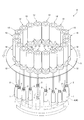
上記電子線滅菌設備には、図1に示すように、未滅菌のペットボトル1が連続して投入される上流側から、滅菌済のペットボトル1が回収される下流側まで、多数のペットボトル1を連続して搬送する搬送装置4が設けられる。また、上記電子線滅菌設備3には、上記搬送装置4に搬送されているペットボトル1の外面に連続して電子線Eを照射する外面電子線照射装置5と、この下流側で上記搬送装置4に搬送されているペットボトル1の内面に連続して電子線Eを照射する内面電子線照射装置6とが設けられる。また、上記電子線Eの照射による滅菌が不十分なペットボトル1は、不良品として廃棄される必要がある。この廃棄を行うリジェクト装置7も、上記電子線滅菌設備3に設けられる。さらに、上記電子線Eの照射により、オゾン(O3)や硝酸(HNO3)などの腐食性ガスが発生する。このような腐食性ガスは、電子線滅菌設備3の各装置4~7を腐食させる原因となるので、上記電子線滅菌設備3の外部に排出される必要がある。この排出を促進する換気装置8も、上記電子線滅菌設備3に設けられる。
次に、上記内面電子線照射装置6について図2および図3に基づき説明する。
次に、上記内面電子線照射装置6について図2および図3に基づき説明する。
この内面電子線照射装置6は、図2に示すように、上記搬送装置4により円経路4Cに搬送される多数のペットボトル1の内面を連続して滅菌するものである。上記内面電子線照射装置6は、上記円経路4Cの上方に位置して当該円経路4Cと同心のターンテーブル11と、このターンテーブル11に多数配置されて上記円経路4Cの直上方に位置する電子線エミッター12とを備える。
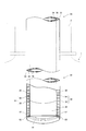
上記ターンテーブル11は、円経路4Cに搬送されるペットボトル1の直上方に一定の電子線エミッター12が位置するように回転するものである。上記電子線エミッター12は、図3に示すように、主として、内部が真空雰囲気の真空チャンバー20と、この真空チャンバー20を上記ターンテーブル11に固定する固定具22と、上記真空チャンバー20から下方に延びる電子線照射ノズル23とから構成される。上記真空チャンバー20は、内部に電子発生源21が配置されることにより、多数の電子eを発生させて下方に加速するものである。上記電子線照射ノズル23は、上記真空チャンバー20に連通して内部が真空雰囲気であり、上記真空チャンバー20で加速された多数の電子eを電子線Eとして下端から出射するものである。したがって、ペットボトル1の内面を滅菌するために、上記電子線照射ノズル23は、図2および図3に示すように、ペットボトル1の内部に開口部2から挿入されながら当該ペットボトル1の内面に電子線Eを照射する必要がある。このため、図3に示すように(図2では省略)、ペットボトル1を昇降させる昇降機24(駆動部の一例である)が内面電子線照射装置6に備えられる。この昇降機24は、上記円経路4Cからペットボトル1を上昇させることにより、上記電子線照射ノズル23をペットボトル1の内部に開口部2から挿入し、その状態からペットボトル1を下降させることにより、上記電子線照射ノズル23をペットボトル1の内部から抜去するものである。上記昇降機24は、ペットボトル1を昇降させるものであれば特に限定されないが、例えば、ペットボトル1を把持するグリッパ25と、このグリッパ25を上下方向に案内するガイド部材26と、このガイド部材26の案内により上記グリッパ25を上下方向に移動させるアクチュエータ(図示省略)とを有する。
上記電子線照射ノズル23は、図3に示すように、その下端に配置されて電子線Eを出射する出射窓41と、この出射窓41を保持するノズル本体31と、このノズル本体31を保護する保護部51とを有する。この保護部51は、ノズル本体31を保護するものであれば、特に限定されない。例えば、上記保護部51は、ノズル本体31に配置された保護用の部材など固体によりノズル本体31と腐食性ガスなどとの接触を防ぐものでもよく、ノズル本体31への気体または液体の吹き込みなど流体によりノズル本体31と腐食性ガスなどとの接触を防ぐものでもよい。
このように、上記内面電子線照射装置6およびこれを具備する電子線滅菌設備3によると、電子線照射ノズル23において、保護部51によりノズル本体31が保護されるので、寿命を長くすることができる。
以下、上記実施の形態をより具体的に示した実施例1~4に係る内面電子線照射装置6およびこれを具備する電子線滅菌設備3について説明する。なお、以下の実施例1~4において、より具体的に示すのは電子線照射ノズル23についての構成であり、それ以外の構成は上記実施の形態と同一であるから説明を省略する。
以下、本実施例1に係る電子線照射ノズル23について図4に基づき詳細に説明する。
図4に示すように、ペットボトル1の内部に開口部2から挿入され得る電子線照射ノズル23は、筒状のノズル本体31と、このノズル本体31の下端で保持されて電子線E(図4~図7では省略)を下方に出射する出射窓41と、上記ノズル本体31の下端を保護するキャップ体52(保護部51の一例である)とを有する。
上記ノズル本体31は、汎用耐食材(例えばステンレス)で構成される汎用耐食部32と、高い熱伝導性を有する材料(例えば銅)で構成される熱伝導部36と、上記汎用耐食部32に溶接しやすくするための材料(例えばニッケル)で構成される溶接親和部37とを有する。上記汎用耐食部32は、外殻33と、この外殻33よりも短い内殻34とからなる2重殻構造である。また、上記汎用耐食部32には、外殻33と内殻34との間に冷却液35を循環させる冷媒空間が形成されている。上記熱伝導部36は、上記電子線Eにより加熱された出射窓41の熱を奪って冷却液35に伝えるために、汎用耐食部32の内殻34における下端に接続される。すなわち、上記熱伝導部36は、汎用耐食部32の内殻34における外殻33より短い部分を補うように配置され、当該外殻33との間にも冷却液35を循環させる冷媒空間が形成されている。
上記出射窓41は、上記汎用耐食材よりも高い耐食性を有する高耐食材(例えばチタン)で構成される箔41およびグリッド(図示省略)である。なお、このグリッドは出射窓41の強度を向上させるものであるから、上記箔41のみで出射窓41の強度が担保されるのであれば、出射窓41の構成からグリッドは省略される。また、上記出射窓41は、上記ノズル本体31の下端とキャップ体52の上端との間に配置される。
上記キャップ体52は、上記汎用耐食材よりも高い耐食性を有する高耐食材(例えばチタン)で構成されるリング形状の部材である。また、上記キャップ体52は、その内側から上記出射窓41を介して電子線Eが適切な横断面で出射されるように、内径が設計される。さらに、上記キャップ体52は、ノズル本体31の下端が電子線照射ノズル23の外部に露出しないように、外径が設計される。具体的に説明すると、上記キャップ体52は、ノズル本体31における下端の外径と比べて同一またはそれ以上の外径を有し、ノズル本体31における下端の内径と比べて同一またはそれ以上の内径を有する。加えて、上記キャップ体52は、図4に示すように、その外周部から下方に延びるように構成される。言い換えれば、上記キャップ体52は、その下端と出射窓41との距離を大きくすることで、当該下端に障害物などが衝突しても、薄くて破れやすい出射窓41まで上記障害物が衝突し難いように構成される。
このように、本実施例1に係る上記内面電子線照射装置6およびこれを具備する電子線滅菌設備3によると、電子線照射ノズル23において、ノズル本体31の下端、すなわちペットボトル1の内部に滞留する腐食性ガスに最も長時間晒される部分がキャップ体52により保護されるので、効率的にノズル本体31が腐食性ガスから保護されることになり、その結果、より寿命を長くすることができる。
また、キャップ体52の下端に障害物などが衝突しても、薄くて破れやすい出射窓41まで上記障害物が衝突し難いので、ノズル本体31および出射窓41が障害物の衝突からも保護されることになり、その結果、より一層寿命を長くすることができる。
以下、本実施例2に係る電子線照射ノズル23について図5に基づき詳細に説明する。
本実施例2に係る電子線照射ノズル23は、保護部51が、上記実施例1で説明したキャップ体52ではなく、ノズル本体31の側面を覆うコーティング53である。なお、本実施例2において、上記実施例1と同一の構成については同一の符号を付して、その説明を省略する。
図5に示すように、ペットボトル1の内部に開口部2から挿入され得る電子線照射ノズル23は、ノズル本体31の側面において、ペットボトル1の内部に開口部2から挿入され得る部分の全面がコーティング53(保護部51の一例)されている。このコーティング53は、例えばチタン膜またはダイヤモンドライクカーボンの皮膜である。
このように、本実施例2に係る上記内面電子線照射装置6およびこれを具備する電子線滅菌設備3によると、ノズル本体31の側面において、ペットボトル1の内部に開口部2から挿入され得る部分の全面がコーティング53により保護されるので、ノズル本体31が広い範囲で腐食性ガスおよび障害物の衝突から保護されることになり、その結果、より寿命を長くすることができる。
以下、本実施例3に係る電子線照射ノズル23について図6に基づき詳細に説明する。
本実施例3に係る電子線照射ノズル23は、保護部51が、上記実施例2で説明したコーティング53ではなく、ノズル本体31を外方で囲う外周管54と、ノズル本体31と外周管54との間に不活性ガスを供給する不活性ガス供給器61である。ここで、本明細書における不活性ガスとは、上記腐食性ガスより活性が低い気体を意味し、空気も含む概念である。なお、本実施例3において、上記実施例1および2と同一の構成については同一の符号を付して、その説明を省略する。
図6に示すように、ペットボトル1の内部に開口部2から挿入され得る電子線照射ノズル23は、ノズル本体31を外方で囲う外周管54(保護部51の一例である)を有する。この外周管54は、ペットボトル1の開口部2を通る(つまり当該開口部2よりも小さい)外径であり、必要に応じて着脱式であってもよい。また、上記外周管54は、ノズル本体31を障害物の衝突から保護するだけでなく、ペットボトル1の外部から内部に不活性ガス(図6では一例として窒素N2ガス)を案内することにより、ペットボトル1の内部に滞留する腐食性ガス(図6では一例としてオゾンO3ガス)を外部に排出するものでもある。このため、上記外周管54は、ノズル本体31との間に通気空間56を形成するように配置されるとともに、電子線照射ノズル23は、ペットボトル1の外部から通気空間56に不活性ガスを供給する不活性ガス供給器61を有する。したがって、上記外周管54は、不活性ガス供給器61により供給された不活性ガスを案内してノズル本体31の先端部から放出させる不活性ガス案内部でもある。
このように、本実施例3に係る上記内面電子線照射装置6およびこれを具備する電子線滅菌設備3によると、ノズル本体31の側面が外周管54により保護されるとともに、外周管54および不活性ガス供給器61によりペットボトル1の内部が腐食性ガスから不活性ガスに置換されるので、ノズル本体31が広い範囲で腐食性ガスおよび障害物の衝突から保護されることになり、その結果、より寿命を長くすることができる。
以下、本実施例4に係る電子線照射ノズル23について図7に基づき詳細に説明する。
本実施例4に係る電子線照射ノズル23は、保護部51が、上記実施例3で説明したノズル本体31を外方で囲う外周管54ではなく、ノズル本体31の外側面に沿って配置された通気管55である。なお、本実施例4において、上記実施例1~3と同一の構成については同一の符号を付して、その説明を省略する。
図7に示すように、ペットボトル1の内部に開口部2から挿入され得る電子線照射ノズル23は、ノズル本体31の外側面に沿って、ノズル本体31の長手方向に配置された2本の通気管55(保護部51の一例である)を有する。これら通気管55は、ノズル本体31とともにペットボトル1の開口部2を通る外径である。上記2本の通気管55は、上記実施例3と同様に、ペットボトル1の内部を腐食性ガス(図7では一例としてオゾンO3ガス)から不活性ガス(図7では一例として窒素N2ガス)に置換するだけでなく、ノズル本体31を障害物の衝突から保護するものでもある。勿論、上記通気管55は、不活性ガス供給器61により供給された不活性ガスを案内してノズル本体31の先端部から放出させる不活性ガス案内部でもある。なお、通気管55は、上記の通り2本に限定されることなく、必要に応じて1本または3本以上が選択される。
このように、本実施例4に係る上記内面電子線照射装置6およびこれを具備する電子線滅菌設備3によると、ノズル本体31の側面が通気管55により保護されるとともに、通気管55および不活性ガス供給器61によりペットボトル1の内部が腐食性ガスから不活性ガスに置換されるので、ノズル本体31が広い範囲で腐食性ガスおよび障害物の衝突から保護されることになり、その結果、より寿命を長くすることができる。
ところで、上記実施の形態および実施例1~4では、汎用耐食部32(例えばステンレス)に出射窓41を溶接しやすい材料(例えばニッケル)で構成される溶接親和部37について説明したが、HIP接合などにより汎用耐食部32および熱伝導部36に出射窓41を直接接合できるのであれば、溶接親和部37を用いなくてもよい。
また、上記実施の形態および実施例1~4では、駆動部の一例として昇降機24について説明したが、これに限定されるものではなく、滅菌対象物の開口部2と電子線照射ノズル23の出射窓41とを接近および離間させるとともに、当該接近の際に滅菌対象物をその内面に電子線Eが照射される状態にするものであればよい。駆動部の他の例としては、ノズル本体31の長手方向に直交する方向に、滅菌対象物をその内面に電子線Eが照射される状態まで搬送する搬送機などである。
さらに、上記実施の形態および実施例1~4では、内面電子線照射装置6において、ノズル本体31の長手方向が鉛直方向であることを前提として説明したが、この方向に限定されるものではなく、必要に応じて適宜変更してもよい。
加えて、保護部51の一例として、実施例1ではキャップ体52、実施例2ではコーティング53、実施例3では外周管54および不活性ガス供給器61、並びに実施例4では通気管55および不活性ガス供給器61について説明したが、これら52~55,61を適宜組み合わせて保護部51としてもよい。
また、上記実施例3および4では、外周管54および通気管55の下端がノズル本体31の下端まで届くように図6で示したが、これは一例に過ぎず、外周管54および通気管55の下端がノズル本体31の下端まで届かなくてもよい。外周管54および通気管55はペットボトル1の内部に滞留する腐食性ガスを不活性ガスに置換するものであるから、外周管54および通気管55の下端は、ペットボトル1の内部に位置する程度の長さであればよい。
Claims (5)
- 開口部が形成された滅菌対象物の内面を電子線の照射により滅菌する内面電子線照射装置であって、
上記滅菌対象物の内面に電子線を照射する電子線照射ノズルが備えられ、
上記電子線照射ノズルが、電子線を出射する出射窓と、この出射窓を保持するノズル本体と、このノズル本体を保護する保護部とを有し、
上記滅菌対象物の開口部と上記電子線照射ノズルの出射窓とを接近および離間させるとともに、当該接近の際に滅菌対象物をその内面に電子線が照射される状態にする駆動部が備えられたことを特徴とする内面電子線照射装置。 - 上記保護部が、ノズル本体の先端に設けられたキャップ体を有することを特徴とする請求項1に記載の内面電子線照射装置。
- 上記保護部が、ノズル本体のコーティングを有することを特徴とする請求項1または2に記載の内面電子線照射装置。
- 上記保護部が、ノズル本体に不活性ガスを供給する不活性ガス供給器と、この不活性ガス供給器により供給された不活性ガスを案内してノズル本体の先端部から放出させる不活性ガス案内部とを有することを特徴とする請求項1または2に記載の内面電子線照射装置。
- 請求項1または2に記載の内面電子線照射装置と、
上記内面電子線照射装置に滅菌対象物を搬送する搬送装置と、
上記搬送装置で搬送されている滅菌対象物の外面を電子線の照射により滅菌する外面電子線照射装置とを具備することを特徴とする電子線滅菌設備。
Applications Claiming Priority (2)
| Application Number | Priority Date | Filing Date | Title |
|---|---|---|---|
| JP2016-151623 | 2016-08-02 | ||
| JP2016151623A JP2018019805A (ja) | 2016-08-02 | 2016-08-02 | 内面電子線照射装置およびこれを具備する電子線滅菌設備 |
Publications (1)
| Publication Number | Publication Date |
|---|---|
| WO2018025459A1 true WO2018025459A1 (ja) | 2018-02-08 |
Family
ID=61072896
Family Applications (1)
| Application Number | Title | Priority Date | Filing Date |
|---|---|---|---|
| PCT/JP2017/016490 Ceased WO2018025459A1 (ja) | 2016-08-02 | 2017-04-26 | 内面電子線照射装置およびこれを具備する電子線滅菌設備 |
Country Status (2)
| Country | Link |
|---|---|
| JP (1) | JP2018019805A (ja) |
| WO (1) | WO2018025459A1 (ja) |
Families Citing this family (2)
| Publication number | Priority date | Publication date | Assignee | Title |
|---|---|---|---|---|
| JPWO2020075846A1 (ja) | 2018-10-11 | 2021-09-02 | サントリーホールディングス株式会社 | 滅菌装置および滅菌方法 |
| JP7198686B2 (ja) * | 2019-03-01 | 2023-01-04 | 日立造船株式会社 | 電子線滅菌設備 |
Citations (6)
| Publication number | Priority date | Publication date | Assignee | Title |
|---|---|---|---|---|
| JP2009035330A (ja) * | 2007-04-19 | 2009-02-19 | Krones Ag | 容器を殺菌する装置 |
| JP2010008386A (ja) * | 2008-06-30 | 2010-01-14 | Iwasaki Electric Co Ltd | 電子線照射装置 |
| JP2011521852A (ja) * | 2008-05-30 | 2011-07-28 | クロネス アーゲー | 電荷担体による容器殺菌装置 |
| JP2014094782A (ja) * | 2012-10-09 | 2014-05-22 | Krones Ag | ビームフィンガのためのビーム保護を有する電子ビームによる容器の殺菌 |
| DE102012108639A1 (de) * | 2012-09-14 | 2014-05-28 | Krones Ag | Vorrichtung zum Sterilisieren von Behältnissen mit kombinierter Gasflüssigkeitskühlung für ein Austrittsfenster |
| WO2015144425A1 (en) * | 2014-03-24 | 2015-10-01 | Tetra Laval Holdings & Finance S.A. | Electron beam emitter |
-
2016
- 2016-08-02 JP JP2016151623A patent/JP2018019805A/ja active Pending
-
2017
- 2017-04-26 WO PCT/JP2017/016490 patent/WO2018025459A1/ja not_active Ceased
Patent Citations (6)
| Publication number | Priority date | Publication date | Assignee | Title |
|---|---|---|---|---|
| JP2009035330A (ja) * | 2007-04-19 | 2009-02-19 | Krones Ag | 容器を殺菌する装置 |
| JP2011521852A (ja) * | 2008-05-30 | 2011-07-28 | クロネス アーゲー | 電荷担体による容器殺菌装置 |
| JP2010008386A (ja) * | 2008-06-30 | 2010-01-14 | Iwasaki Electric Co Ltd | 電子線照射装置 |
| DE102012108639A1 (de) * | 2012-09-14 | 2014-05-28 | Krones Ag | Vorrichtung zum Sterilisieren von Behältnissen mit kombinierter Gasflüssigkeitskühlung für ein Austrittsfenster |
| JP2014094782A (ja) * | 2012-10-09 | 2014-05-22 | Krones Ag | ビームフィンガのためのビーム保護を有する電子ビームによる容器の殺菌 |
| WO2015144425A1 (en) * | 2014-03-24 | 2015-10-01 | Tetra Laval Holdings & Finance S.A. | Electron beam emitter |
Also Published As
| Publication number | Publication date |
|---|---|
| JP2018019805A (ja) | 2018-02-08 |
Similar Documents
| Publication | Publication Date | Title |
|---|---|---|
| JP6007279B2 (ja) | 電荷担体による容器殺菌装置 | |
| JP6084765B2 (ja) | 容器を殺菌するための装置 | |
| JP5438325B2 (ja) | ボトルの内部を照射する方法 | |
| CN101310773B (zh) | 容器消毒装置、系统和方法 | |
| US9343190B2 (en) | Apparatus for screening off radiation during the sterilization of containers | |
| JP2010524784A (ja) | Pet容器及びボトルのための殺菌システム | |
| US20150069271A1 (en) | System for sterilising plastic parisons with simultaneous internal and external sterilization | |
| EP3047958A1 (en) | Blow molding device | |
| CN101568472A (zh) | 容器杀菌装置 | |
| WO2018025459A1 (ja) | 内面電子線照射装置およびこれを具備する電子線滅菌設備 | |
| CN106029112A (zh) | 灭菌装置和电子束发射器 | |
| JP6227966B2 (ja) | ビームフィンガのためのビーム保護を有する電子ビームによる容器の殺菌 | |
| JP6502681B2 (ja) | ブロー成形装置 | |
| JPWO2016059990A1 (ja) | 電子線滅菌設備 | |
| CN103083695B (zh) | 用于通过介质控制电子束为塑料材料容器消毒的装置 | |
| US10398794B2 (en) | Internal surface electron beam-irradiating device | |
| CN103157121A (zh) | 容器紫外线消毒的装置、机构和方法 | |
| JP2018508933A (ja) | 低ピッチのノズルを有する電子線エミッタ及びその電子線エミッタを備える電子線滅菌システム | |
| EP2634776B1 (en) | Electron beam irradiation apparatus | |
| JP6635932B2 (ja) | 電子線滅菌設備 | |
| WO2016136423A1 (ja) | 内面電子線照射装置 | |
| WO2018235850A1 (ja) | プリフォームの加熱装置及びプリフォームの加熱方法 | |
| JP2017518935A (ja) | パルス電子衝撃による容器のキャップまたは首部の汚染除去方法およびシステム | |
| JP6846142B2 (ja) | 電子線照射装置およびその使用方法 | |
| JP2025188333A (ja) | 無菌充填方法および無菌充填システム |
Legal Events
| Date | Code | Title | Description |
|---|---|---|---|
| 121 | Ep: the epo has been informed by wipo that ep was designated in this application |
Ref document number: 17836566 Country of ref document: EP Kind code of ref document: A1 |
|
| NENP | Non-entry into the national phase |
Ref country code: DE |
|
| 122 | Ep: pct application non-entry in european phase |
Ref document number: 17836566 Country of ref document: EP Kind code of ref document: A1 |