WO2018024569A1 - Household appliance having a power module with dynamically controlled switching frequency - Google Patents
Household appliance having a power module with dynamically controlled switching frequency Download PDFInfo
- Publication number
- WO2018024569A1 WO2018024569A1 PCT/EP2017/068862 EP2017068862W WO2018024569A1 WO 2018024569 A1 WO2018024569 A1 WO 2018024569A1 EP 2017068862 W EP2017068862 W EP 2017068862W WO 2018024569 A1 WO2018024569 A1 WO 2018024569A1
- Authority
- WO
- WIPO (PCT)
- Prior art keywords
- motor
- speed
- household appliance
- switching frequency
- predefined speed
- Prior art date
- Legal status (The legal status is an assumption and is not a legal conclusion. Google has not performed a legal analysis and makes no representation as to the accuracy of the status listed.)
- Ceased
Links
Images
Classifications
-
- H—ELECTRICITY
- H02—GENERATION; CONVERSION OR DISTRIBUTION OF ELECTRIC POWER
- H02P—CONTROL OR REGULATION OF ELECTRIC MOTORS, ELECTRIC GENERATORS OR DYNAMO-ELECTRIC CONVERTERS; CONTROLLING TRANSFORMERS, REACTORS OR CHOKE COILS
- H02P6/00—Arrangements for controlling synchronous motors or other dynamo-electric motors using electronic commutation dependent on the rotor position; Electronic commutators therefor
- H02P6/14—Electronic commutators
- H02P6/16—Circuit arrangements for detecting position
- H02P6/18—Circuit arrangements for detecting position without separate position detecting elements
-
- D—TEXTILES; PAPER
- D06—TREATMENT OF TEXTILES OR THE LIKE; LAUNDERING; FLEXIBLE MATERIALS NOT OTHERWISE PROVIDED FOR
- D06F—LAUNDERING, DRYING, IRONING, PRESSING OR FOLDING TEXTILE ARTICLES
- D06F34/00—Details of control systems for washing machines, washer-dryers or laundry dryers
- D06F34/10—Power supply arrangements, e.g. stand-by circuits
-
- D—TEXTILES; PAPER
- D06—TREATMENT OF TEXTILES OR THE LIKE; LAUNDERING; FLEXIBLE MATERIALS NOT OTHERWISE PROVIDED FOR
- D06F—LAUNDERING, DRYING, IRONING, PRESSING OR FOLDING TEXTILE ARTICLES
- D06F37/00—Details specific to washing machines covered by groups D06F21/00 - D06F25/00
- D06F37/30—Driving arrangements
- D06F37/304—Arrangements or adaptations of electric motors
-
- D—TEXTILES; PAPER
- D06—TREATMENT OF TEXTILES OR THE LIKE; LAUNDERING; FLEXIBLE MATERIALS NOT OTHERWISE PROVIDED FOR
- D06F—LAUNDERING, DRYING, IRONING, PRESSING OR FOLDING TEXTILE ARTICLES
- D06F25/00—Washing machines with receptacles, e.g. perforated, having a rotary movement, e.g. oscillatory movement, the receptacle serving both for washing and for centrifugally separating water from the laundry and having further drying means, e.g. using hot air
-
- Y—GENERAL TAGGING OF NEW TECHNOLOGICAL DEVELOPMENTS; GENERAL TAGGING OF CROSS-SECTIONAL TECHNOLOGIES SPANNING OVER SEVERAL SECTIONS OF THE IPC; TECHNICAL SUBJECTS COVERED BY FORMER USPC CROSS-REFERENCE ART COLLECTIONS [XRACs] AND DIGESTS
- Y02—TECHNOLOGIES OR APPLICATIONS FOR MITIGATION OR ADAPTATION AGAINST CLIMATE CHANGE
- Y02B—CLIMATE CHANGE MITIGATION TECHNOLOGIES RELATED TO BUILDINGS, e.g. HOUSING, HOUSE APPLIANCES OR RELATED END-USER APPLICATIONS
- Y02B40/00—Technologies aiming at improving the efficiency of home appliances, e.g. induction cooking or efficient technologies for refrigerators, freezers or dish washers
Definitions
- a synchronous machine is an electrical machine with a rotating stator magnetic flux and a rotor flux locked therewith to rotate in the synchronous frequency.
- a brushless DC (BLDC) motor and brushless AC (BLAC) are a kind of synchronous motor that has trapezoidal back-EMF voltage and sinusoidal back-EMF shape.
- washing machines may have a jet pump for spraying water jets into the rotary drum targeting at specific regions inside it, at which the laundry may tend to adhere within the same, as well as a discharge pump for discharging the water contained in the drum.
- a washing and/or drying machine may have a discharge pump as well as a circulation pump for circulating washing water.
- One of the well-known Vector control method involves positionment of the rotor by a microcontroller.
- the BLDC or BLAC motor is used in various applications due to its compact size and easy controllability. It is usually operated with one or more rotor-position sensors.
- the motor control can be performed without making use of Hall sensors or any kind of position sensor in the manner that the motor position is estimated thanks to the information provided by the currents flowing through the motor coils.
- a three-phase inverter driver circuit can typically be used to drive the BLDC motor.
- the semiconductor switches in the power module with the inverter drivers collected in a single package in the form of an integrated power module (IPM) can be of different types such as; MOSFET, IGBT, etc.
- Power switches in the power module cause switching losses as well as transmission losses. Transmission losses basically depend on the inner resistance (R ds ) in a given power switch such as a MOSFET or formed saturation voltage on given power switch such as a IGBT. As the current through the power switch increases, the loss also increases. Increased losses generate heat and further increase the power module’s temperature. Switching frequency is proportional to switching losses. Increased frequency also increases switching losses, whereas transmission losses generate heat and this in turn causes the power module’s temperature to rise up. To reduce switching losses, sophisticated circuit topologies involving soft switching techniques should be used. This will, however, increase the total cost of the designed system.
- household appliance motors may require a dynamically regulated switching frequency for the switching elements in the power inverter module.
- the drum can be rotated at different speeds depending on the specific washing and/or drying cycle and the switching frequency can be dynamically adapted to the specific treatment stage.
- current sampling resolution may not be adequate to ensure sensorless motor control.
- the switching frequency can be controlled in accordance with the motor speed, also simultaneously allowing a sufficiently increased switching frequency at higher motor speeds so as to ensure sensorless motor control with a sufficient current sampling frequency.
- KR20010073638 discloses a compressor noise reducing device having a power supply, an inverter for driving a brushless direct current (BLDC) motor by receiving the power from the power supply and the control signal, a rotor position and speed detection unit for detecting the rotor position of the BLDC motor and for calculating the speed using the measured position data, a proportional integral controller for controlling the duty ratio of the PWM by proportioning and integrating the difference value between the reference value and the calculated speed, a random variable generator for generating the random numbers, a PWM frequency determination unit for determining the PWM frequency using the random signal, a PWM comparable signal generator for producing the PWM frequency period and the on-time according to the determined PWM frequency, and a gate signal generator for producing the gate signal to turn on or off the switching elements of the inverter by using PWM pulse.
- BLDC brushless direct current
- US2013043811 discloses Field Oriented Control (FOC) of a BLDC motor with a single shunt.
- FOC Field Oriented Control
- the present invention provides a control scheme capable of reducing switching losses and also simultaneously allowing a sufficiently increased switching frequency at higher motor speeds so as to ensure sensorless motor control with a sufficient current sampling frequency.
- Primary object of the present invention is therefore to provide an electrical household appliance with a BLDC or BLAC motor control scheme by which more efficient motor operation is ensured in sensorless vector control.
- the present invention proposes an electrical household appliance comprising an inverter power module in the form of a six-switch three-phase inverter connected to a DC link.
- PWM frequency is dynamically changed in accordance with the operational state of the electric motor to lower switching losses at lower speeds and to ensure current sampling at higher speeds.
- the present invention proposes an electrical household appliance and particularly a washing machine, a dishwasher, a drying machine or a combo drying and washing machine, which might contain an electric motor in the form of a brushless DC (BLDC) motor or BLAC motor to fulfill various functions, for instance in a washing machine, such as for instance driving a jet pump for spraying water jets into the rotary drum targeting at specific regions inside the same, at which the laundry may tend to adhere within the same, driving a discharge pump for discharging the water contained in the drum or driving a discharge pump as well as a circulation pump for circulating water.
- BLDC brushless DC
- the electrical household appliance comprises a power module (1) driving a BLDC or BLAC motor having three phases (phase A, phase B and phase C, respectively 2, 3 and 4).
- High side power switches (6, HIN1, HIN2, HIN3)) and low side power switches (7, LIN1, LIN2, LIN3) of the power module (1) are typically provided with freewheeling diodes (5) allowing reverse current to flow therethrough to be dissipated. Phase windings are thereby deenergized through respective freewheeling diodes (5) and the stored magnetic energy in the respective phases is dissipated.
- the BLDC or BLAC motor control is conventionally performed without making use of Hall sensors, by way of using Field Oriented Control (FOC) such that the motor position is estimated thanks to the information provided by the currents flowing through the motor coils.
- FOC Field Oriented Control
- Current flowing through the DC bus is used to reconstruct the three-phase currents and to estimate motor position using a single shunt and a differential amplifier.
- the amount of current flowing through each phase (2, 3, 4) can also be determined using shunt resistors (not shown) on each phase.
- two-shunt method can be used to reconstruct the currents by measuring current from two legs and reconstructing the third current using Kirchhoff’s law.
- US2015022131 discloses current sensors in the form of shunt resistors.
- the present invention proposes a control scheme according to which switching losses are reduced by decreasing the switching frequency. While at lower motor speeds, a lower switching frequency being proportional to the current sampling frequency can be the case, at higher motor speeds, a higher current sampling frequency will be needed.
- a speed dependent switching frequency control BLDC or BLAC motor is advantageous in that longer duration motor operations such as washing cycles at lower speeds can be effectuated with less switching losses and operations requiring higher speeds such as the spin-drying cycle are effectuated at higher switching frequencies to ensure sensorless position control. In other words, reducing the PWM frequency lowers switching losses while not affecting sound commutation; when spinning faster, however, higher sampling frequencies are needed.
- the invention proposes to dynamically change the PWM frequency.
- a first switching frequency is used.
- a second switching frequency is used.
- the PWM frequency level setting as determined by a frequency flag (FF, 0 or 1) during the previous adaptation is used.
- SVPWM Space Vector Pulse Width Modulation
- the present invention proposes an electrical household appliance comprising an electric motor, a driver circuit capable of driving said electric motor, said driver circuit comprising a converter that converts AC mains voltage to DC voltage, a driver circuit inverter stage that inverts the direct current, said driver circuit inverter stage comprising an inverter power module (1) having high side and low side power switches (6, 7) with freewheeling diodes (5) in the form of a six-switch three-phase inverter connected to a DC bus, said electric motor being a brushless DC motor and motor position being determined in the manner that currents flowing through motor phases (2, 3, 4) are recreated.
- PWM frequency of the power module (1) is dynamically changed in the manner that if the motor speed is less than a first predefined speed, a first switching frequency is applied and if the motor speed is greater than a second predefined speed that is also greater than the first predefined speed, a second switching frequency greater than the first switching frequency is applied and finally, if the motor speed is greater than the first predefined speed but less than said second predefined speed, than the PWM frequency is set to either the first or the second switching frequency.
- the PWM frequency level setting is determined according to the value of a one bit frequency flag.
- said one bit frequency flag is set to 1 if the motor speed is less than said first predefined speed and set to 1 if the motor speed is greater than said second predefined speed.
- said electrical household appliance is a washing machine, a dishwasher, a drying machine or a combo drying and washing machine.
- said electrical household appliance is a washing and/or drying machine and said electric motor rotates drum of said washing and/or drying machine.
- said method comprises the steps of dynamically changing PWM frequency of a power module (1) driving a BLDC or BLAC motor of said electrical household appliance in the manner that if the motor speed is less than a first predefined speed, a first switching frequency is applied and if the motor speed is greater than a second predefined speed that is also greater than the first predefined speed, a second switching frequency greater than the first switching frequency is applied and finally, if the motor speed is greater than the first predefined speed but less than said second predefined speed, than the PWM frequency is set to either the first or the second switching frequency.
- the present invention ensures a control scheme capable of effectuating BLDC or BLAC motor sensorless control operation at the same time lowering switching losses by the power switches (6, 7).
Landscapes
- Engineering & Computer Science (AREA)
- Textile Engineering (AREA)
- Power Engineering (AREA)
- Control Of Motors That Do Not Use Commutators (AREA)
- Control Of Ac Motors In General (AREA)
Abstract
The present invention relates to an electrical household appliance with a power module with dynamically controlled switching frequency. The present invention more particularly relates to an electrical household appliance comprising an electric motor, a driver circuit capable of driving said electric motor, said driver circuit comprising a converter that converts AC mains voltage to DC voltage, a driver circuit inverter stage that inverts the direct current, said driver circuit inverter stage comprising an inverter power module (1 ) having high side and low side power switches (6, 7) with freewheeling diodes (5) in the form of a six-switch three-phase inverter connected to a DC bus, said electric motor being a brushless DC motor and motor position being determined in the manner that currents flowing through motor phases (2, 3, 4) are recreated.
Description
The present invention relates to an electrical household appliance with a power module with dynamically controlled switching frequency.
It is well-known that a synchronous machine is an electrical machine with a rotating stator magnetic flux and a rotor flux locked therewith to rotate in the synchronous frequency. A brushless DC (BLDC) motor and brushless AC (BLAC) are a kind of synchronous motor that has trapezoidal back-EMF voltage and sinusoidal back-EMF shape.
It is also well-known that synchronous motors are widely used in rotary household appliances and especially in dishwashers and laundry treatment appliances. For instance, washing machines may have a jet pump for spraying water jets into the rotary drum targeting at specific regions inside it, at which the laundry may tend to adhere within the same, as well as a discharge pump for discharging the water contained in the drum. Likewise, a washing and/or drying machine may have a discharge pump as well as a circulation pump for circulating washing water.
One of the well-known Vector control method involves positionment of the rotor by a microcontroller. The BLDC or BLAC motor is used in various applications due to its compact size and easy controllability. It is usually operated with one or more rotor-position sensors. However, the motor control can be performed without making use of Hall sensors or any kind of position sensor in the manner that the motor position is estimated thanks to the information provided by the currents flowing through the motor coils.
A three-phase inverter driver circuit can typically be used to drive the BLDC motor. The semiconductor switches in the power module with the inverter drivers collected in a single package in the form of an integrated power module (IPM) can be of different types such as; MOSFET, IGBT, etc. Power switches in the power module cause switching losses as well as transmission losses. Transmission losses basically depend on the inner resistance (Rds) in a given power switch such as a MOSFET or formed saturation voltage on given power switch such as a IGBT. As the current through the power switch increases, the loss also increases. Increased losses generate heat and further increase the power module’s temperature. Switching frequency is proportional to switching losses. Increased frequency also increases switching losses, whereas transmission losses generate heat and this in turn causes the power module’s temperature to rise up. To reduce switching losses, sophisticated circuit topologies involving soft switching techniques should be used. This will, however, increase the total cost of the designed system.
It is particularly noted that household appliance motors may require a dynamically regulated switching frequency for the switching elements in the power inverter module. In the case of a laundry treatment appliance, the drum can be rotated at different speeds depending on the specific washing and/or drying cycle and the switching frequency can be dynamically adapted to the specific treatment stage. On the other hand, in the case of sensorless motor control, current sampling resolution may not be adequate to ensure sensorless motor control. To this end, in order for reducing switching losses, the switching frequency can be controlled in accordance with the motor speed, also simultaneously allowing a sufficiently increased switching frequency at higher motor speeds so as to ensure sensorless motor control with a sufficient current sampling frequency.
Among others, one of the prior art disclosures in the technical field of the present invention can be referred to as KR20010073638, which discloses a compressor noise reducing device having a power supply, an inverter for driving a brushless direct current (BLDC) motor by receiving the power from the power supply and the control signal, a rotor position and speed detection unit for detecting the rotor position of the BLDC motor and for calculating the speed using the measured position data, a proportional integral controller for controlling the duty ratio of the PWM by proportioning and integrating the difference value between the reference value and the calculated speed, a random variable generator for generating the random numbers, a PWM frequency determination unit for determining the PWM frequency using the random signal, a PWM comparable signal generator for producing the PWM frequency period and the on-time according to the determined PWM frequency, and a gate signal generator for producing the gate signal to turn on or off the switching elements of the inverter by using PWM pulse.
Further, US2013043811 discloses Field Oriented Control (FOC) of a BLDC motor with a single shunt.
The present invention, on the other hand, provides a control scheme capable of reducing switching losses and also simultaneously allowing a sufficiently increased switching frequency at higher motor speeds so as to ensure sensorless motor control with a sufficient current sampling frequency.
Primary object of the present invention is therefore to provide an electrical household appliance with a BLDC or BLAC motor control scheme by which more efficient motor operation is ensured in sensorless vector control.
The present invention proposes an electrical household appliance comprising an inverter power module in the form of a six-switch three-phase inverter connected to a DC link. PWM frequency is dynamically changed in accordance with the operational state of the electric motor to lower switching losses at lower speeds and to ensure current sampling at higher speeds.
Accompanying drawings are given solely for the purpose of exemplifying a household appliance having a BLDC or BLAC motor and a control module whose advantages over prior art were outlined above and will be explained in brief hereinafter.
The drawings are not meant to delimit the scope of protection as identified in the claims nor should they be referred to alone in an effort to interpret the scope identified in said claims without recourse to the technical disclosure in the description of the present invention.
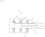
Fig. 1 demonstrates a conventional inverter module with high side and low side power switches.
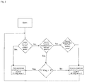
Fig. 2 demonstrates a control scheme for effectuating sensorless control of a BLDC or BLAC motor according to the present invention.
The following numerals being referred to are used in the detailed description of the invention:
- Power module
- Phase A
- Phase B
- Phase C
- Freewheeling diode
- High side power switch
- Low side power switch
The present invention proposes an electrical household appliance and particularly a washing machine, a dishwasher, a drying machine or a combo drying and washing machine, which might contain an electric motor in the form of a brushless DC (BLDC) motor or BLAC motor to fulfill various functions, for instance in a washing machine, such as for instance driving a jet pump for spraying water jets into the rotary drum targeting at specific regions inside the same, at which the laundry may tend to adhere within the same, driving a discharge pump for discharging the water contained in the drum or driving a discharge pump as well as a circulation pump for circulating water.
The electrical household appliance comprises a power module (1) driving a BLDC or BLAC motor having three phases (phase A, phase B and phase C, respectively 2, 3 and 4). High side power switches (6, HIN1, HIN2, HIN3)) and low side power switches (7, LIN1, LIN2, LIN3) of the power module (1) are typically provided with freewheeling diodes (5) allowing reverse current to flow therethrough to be dissipated. Phase windings are thereby deenergized through respective freewheeling diodes (5) and the stored magnetic energy in the respective phases is dissipated.
The BLDC or BLAC motor control is conventionally performed without making use of Hall sensors, by way of using Field Oriented Control (FOC) such that the motor position is estimated thanks to the information provided by the currents flowing through the motor coils. Current flowing through the DC bus is used to reconstruct the three-phase currents and to estimate motor position using a single shunt and a differential amplifier.
As is known to the skilled reader, the amount of current flowing through each phase (2, 3, 4) can also be determined using shunt resistors (not shown) on each phase. Alternatively, two-shunt method can be used to reconstruct the currents by measuring current from two legs and reconstructing the third current using Kirchhoff’s law. For instance US2015022131 discloses current sensors in the form of shunt resistors.
To this end, the present invention proposes a control scheme according to which switching losses are reduced by decreasing the switching frequency. While at lower motor speeds, a lower switching frequency being proportional to the current sampling frequency can be the case, at higher motor speeds, a higher current sampling frequency will be needed. A speed dependent switching frequency control BLDC or BLAC motor is advantageous in that longer duration motor operations such as washing cycles at lower speeds can be effectuated with less switching losses and operations requiring higher speeds such as the spin-drying cycle are effectuated at higher switching frequencies to ensure sensorless position control. In other words, reducing the PWM frequency lowers switching losses while not affecting sound commutation; when spinning faster, however, higher sampling frequencies are needed.
Therefore, to increase sampling resolution at higher speeds, the invention proposes to dynamically change the PWM frequency. In reference to Figure 2, in the event that the motor speed is less than a first predefined speed, then a first switching frequency is used. On the other hand, if the motor speed is greater than a second predefined speed that is also greater than the first predefined speed, then a second switching frequency greater than the first switching frequency is used. Finally, if the motor speed is greater than the first predefined speed but less than said second predefined speed, than the PWM frequency level setting as determined by a frequency flag (FF, 0 or 1) during the previous adaptation is used.
Space Vector Pulse Width Modulation (SVPWM) is used as the PWM technique to operate the power switches.
In a nutshell, the present invention proposes an electrical household appliance comprising an electric motor, a driver circuit capable of driving said electric motor, said driver circuit comprising a converter that converts AC mains voltage to DC voltage, a driver circuit inverter stage that inverts the direct current, said driver circuit inverter stage comprising an inverter power module (1) having high side and low side power switches (6, 7) with freewheeling diodes (5) in the form of a six-switch three-phase inverter connected to a DC bus, said electric motor being a brushless DC motor and motor position being determined in the manner that currents flowing through motor phases (2, 3, 4) are recreated.
In one embodiment of the present invention, PWM frequency of the power module (1) is dynamically changed in the manner that if the motor speed is less than a first predefined speed, a first switching frequency is applied and if the motor speed is greater than a second predefined speed that is also greater than the first predefined speed, a second switching frequency greater than the first switching frequency is applied and finally, if the motor speed is greater than the first predefined speed but less than said second predefined speed, than the PWM frequency is set to either the first or the second switching frequency.
In a further embodiment of the present invention, if the motor speed is greater than the first predefined speed but less than said second predefined speed, the PWM frequency level setting is determined according to the value of a one bit frequency flag.
In a further embodiment of the present invention, said one bit frequency flag is set to 1 if the motor speed is less than said first predefined speed and set to 1 if the motor speed is greater than said second predefined speed.
In a further embodiment of the present invention, said electrical household appliance is a washing machine, a dishwasher, a drying machine or a combo drying and washing machine.
In a further embodiment of the present invention, said electrical household appliance is a washing and/or drying machine and said electric motor rotates drum of said washing and/or drying machine.
In a further embodiment of the present invention, said method comprises the steps of dynamically changing PWM frequency of a power module (1) driving a BLDC or BLAC motor of said electrical household appliance in the manner that if the motor speed is less than a first predefined speed, a first switching frequency is applied and if the motor speed is greater than a second predefined speed that is also greater than the first predefined speed, a second switching frequency greater than the first switching frequency is applied and finally, if the motor speed is greater than the first predefined speed but less than said second predefined speed, than the PWM frequency is set to either the first or the second switching frequency.
Accordingly, the present invention ensures a control scheme capable of effectuating BLDC or BLAC motor sensorless control operation at the same time lowering switching losses by the power switches (6, 7).
Claims (6)
- An electrical household appliance comprising an electric motor, a driver circuit capable of driving said electric motor, said driver circuit comprising a converter that converts AC mains voltage to DC voltage, a driver circuit inverter stage that inverts the direct current, said driver circuit inverter stage comprising an inverter power module (1) having high side and low side power switches (6, 7) with freewheeling diodes (5) in the form of a six-switch three-phase inverter connected to a DC bus, said electric motor being a brushless DC motor and motor position being determined in the manner that currents flowing through motor phases (2, 3, 4) are recreated characterized in that;PWM frequency of the power module (1) is dynamically changed in the manner that if the motor speed is less than a first predefined speed, a first switching frequency is applied, if the motor speed is greater than a second predefined speed that is greater than the first predefined speed, a second switching frequency greater than the first switching frequency is applied and if the motor speed is greater than the first predefined speed but less than said second predefined speed, the PWM frequency is set to either the first or the second switching frequency.
- An electrical household appliance as in Claim 1, characterized in that if the motor speed is greater than the first predefined speed but less than said second predefined speed, the PWM frequency level setting is determined according to the value of a one bit frequency flag.
- An electrical household appliance as in Claim 2, characterized in that said one bit frequency flag is set to 1 if the motor speed is less than said first predefined speed and set to 1 if the motor speed is greater than said second predefined speed.
- An electrical household appliance as in any preceding Claims, characterized in that said electrical household appliance is a washing machine, a dishwasher, a drying machine or a combo drying and washing machine.
- An electrical household appliance as in Claim 4, characterized in that said electrical household appliance is a washing and/or drying machine and said electric motor drives drum of said washing and/or drying machine.
- A method for controlling operation of an electrical household appliance as in Claim 1, characterized in that said method comprises the steps of dynamically changing PWM frequency of a power module (1) driving a BLDC or BLAC motor of said electrical household appliance in the manner that if the motor speed is less than a first predefined speed, a first switching frequency is applied and if the motor speed is greater than a second predefined speed that is also greater than the first predefined speed, a second switching frequency greater than the first switching frequency is applied and finally, if the motor speed is greater than the first predefined speed but less than said second predefined speed, than the PWM frequency is set to either the first or the second switching frequency.
Applications Claiming Priority (2)
| Application Number | Priority Date | Filing Date | Title |
|---|---|---|---|
| TR2016/10873A TR201610873A2 (en) | 2016-08-03 | 2016-08-03 | Household appliance having a power module with dynamically controlled switching frequency |
| TRA2016/10873 | 2016-08-03 |
Publications (1)
| Publication Number | Publication Date |
|---|---|
| WO2018024569A1 true WO2018024569A1 (en) | 2018-02-08 |
Family
ID=59649654
Family Applications (1)
| Application Number | Title | Priority Date | Filing Date |
|---|---|---|---|
| PCT/EP2017/068862 Ceased WO2018024569A1 (en) | 2016-08-03 | 2017-07-26 | Household appliance having a power module with dynamically controlled switching frequency |
Country Status (2)
| Country | Link |
|---|---|
| TR (1) | TR201610873A2 (en) |
| WO (1) | WO2018024569A1 (en) |
Cited By (1)
| Publication number | Priority date | Publication date | Assignee | Title |
|---|---|---|---|---|
| CN114365404A (en) * | 2019-09-11 | 2022-04-15 | 通力股份公司 | Method for reducing thermal stress of power semiconductor switch, electric converter unit and elevator |
Citations (6)
| Publication number | Priority date | Publication date | Assignee | Title |
|---|---|---|---|---|
| KR20010073638A (en) | 2000-01-19 | 2001-08-01 | 구자홍 | Apparatus for reducing noise of the compressor using random pulse width modulation and control method thereof |
| WO2011024339A1 (en) * | 2009-08-24 | 2011-03-03 | パナソニック株式会社 | Motor driving device and motor driving method |
| JP2011066949A (en) * | 2009-09-15 | 2011-03-31 | Hitachi Appliances Inc | Inverter, and air conditioner, and washing machine and refrigerator each using the inverter |
| EP2388905A1 (en) * | 2009-01-14 | 2011-11-23 | Panasonic Corporation | Motor drive device and electric equipment utilizing same |
| US20130043811A1 (en) | 2011-08-16 | 2013-02-21 | Texas Instruments Incorporated | Field oriented control of a motor with a single shunt |
| US20150022131A1 (en) | 2013-07-22 | 2015-01-22 | Stmicroelectronics S.R.L. | Electric circuit and method for estimating the angular position of a rotor of an electric motor, and device for controlling an electric motor |
-
2016
- 2016-08-03 TR TR2016/10873A patent/TR201610873A2/en unknown
-
2017
- 2017-07-26 WO PCT/EP2017/068862 patent/WO2018024569A1/en not_active Ceased
Patent Citations (6)
| Publication number | Priority date | Publication date | Assignee | Title |
|---|---|---|---|---|
| KR20010073638A (en) | 2000-01-19 | 2001-08-01 | 구자홍 | Apparatus for reducing noise of the compressor using random pulse width modulation and control method thereof |
| EP2388905A1 (en) * | 2009-01-14 | 2011-11-23 | Panasonic Corporation | Motor drive device and electric equipment utilizing same |
| WO2011024339A1 (en) * | 2009-08-24 | 2011-03-03 | パナソニック株式会社 | Motor driving device and motor driving method |
| JP2011066949A (en) * | 2009-09-15 | 2011-03-31 | Hitachi Appliances Inc | Inverter, and air conditioner, and washing machine and refrigerator each using the inverter |
| US20130043811A1 (en) | 2011-08-16 | 2013-02-21 | Texas Instruments Incorporated | Field oriented control of a motor with a single shunt |
| US20150022131A1 (en) | 2013-07-22 | 2015-01-22 | Stmicroelectronics S.R.L. | Electric circuit and method for estimating the angular position of a rotor of an electric motor, and device for controlling an electric motor |
Cited By (1)
| Publication number | Priority date | Publication date | Assignee | Title |
|---|---|---|---|---|
| CN114365404A (en) * | 2019-09-11 | 2022-04-15 | 通力股份公司 | Method for reducing thermal stress of power semiconductor switch, electric converter unit and elevator |
Also Published As
| Publication number | Publication date |
|---|---|
| TR201610873A2 (en) | 2018-02-21 |
Similar Documents
| Publication | Publication Date | Title |
|---|---|---|
| JP4363169B2 (en) | Dishwasher motor drive | |
| KR100659423B1 (en) | Motor driving device | |
| JP6361018B2 (en) | Inverter device and washing machine equipped with the same | |
| WO2018024571A1 (en) | Household appliance having a power module with continuous and discontinuous pwm control | |
| JP2017093534A (en) | Washing machine | |
| WO2015078524A1 (en) | Household appliance with multiple synchronous motors and control circuit thereof | |
| JP2003135883A (en) | Washing machine motor drive | |
| KR101635551B1 (en) | Motor driving device and dish washing machine including the same | |
| CN102347719A (en) | Motor assembly and household appliance with same | |
| CN111434023B (en) | Motor drive device and household appliances having the motor drive device | |
| JP4103354B2 (en) | Motor drive device for washing machine | |
| WO2018024569A1 (en) | Household appliance having a power module with dynamically controlled switching frequency | |
| US9716462B2 (en) | Method for actuating a brushless motor | |
| JP2005057858A (en) | Motor drive device and motor drive device for dishwasher | |
| JP4007054B2 (en) | Washing machine | |
| WO2018141394A1 (en) | Household appliance with brushless dc motor sensorless control scheme | |
| CN102714476B (en) | For the control card of brshless DC motor | |
| KR20090087585A (en) | Motor, washing machine comprising the same and control method thereof | |
| KR101413180B1 (en) | Motor drive apparatus for washing machine and control method thereof | |
| KR101400242B1 (en) | Motor drive circuit for washing machine and control method thereof | |
| JP7522964B2 (en) | washing machine | |
| JP5404810B2 (en) | Operation method of brushless DC motor | |
| KR102674034B1 (en) | Motor driving apparatus and laundry treating appratus with the same | |
| KR101400539B1 (en) | Motor and controlling system for the motor, controlling method for the motor, and waching machine | |
| WO2018001512A1 (en) | Household appliance with a power module having decreased freewheeling time duration |
Legal Events
| Date | Code | Title | Description |
|---|---|---|---|
| 121 | Ep: the epo has been informed by wipo that ep was designated in this application |
Ref document number: 17754082 Country of ref document: EP Kind code of ref document: A1 |
|
| NENP | Non-entry into the national phase |
Ref country code: DE |
|
| 122 | Ep: pct application non-entry in european phase |
Ref document number: 17754082 Country of ref document: EP Kind code of ref document: A1 |