WO2018021095A1 - 液化石油ガス運搬船用ボイルオフガス処理システム - Google Patents
液化石油ガス運搬船用ボイルオフガス処理システム Download PDFInfo
- Publication number
- WO2018021095A1 WO2018021095A1 PCT/JP2017/025971 JP2017025971W WO2018021095A1 WO 2018021095 A1 WO2018021095 A1 WO 2018021095A1 JP 2017025971 W JP2017025971 W JP 2017025971W WO 2018021095 A1 WO2018021095 A1 WO 2018021095A1
- Authority
- WO
- WIPO (PCT)
- Prior art keywords
- gas
- boil
- liquefied petroleum
- processing system
- tank
- Prior art date
- Legal status (The legal status is an assumption and is not a legal conclusion. Google has not performed a legal analysis and makes no representation as to the accuracy of the status listed.)
- Ceased
Links
Images

Classifications
-
- F—MECHANICAL ENGINEERING; LIGHTING; HEATING; WEAPONS; BLASTING
- F02—COMBUSTION ENGINES; HOT-GAS OR COMBUSTION-PRODUCT ENGINE PLANTS
- F02M—SUPPLYING COMBUSTION ENGINES IN GENERAL WITH COMBUSTIBLE MIXTURES OR CONSTITUENTS THEREOF
- F02M21/00—Apparatus for supplying engines with non-liquid fuels, e.g. gaseous fuels stored in liquid form
- F02M21/02—Apparatus for supplying engines with non-liquid fuels, e.g. gaseous fuels stored in liquid form for gaseous fuels
-
- F—MECHANICAL ENGINEERING; LIGHTING; HEATING; WEAPONS; BLASTING
- F17—STORING OR DISTRIBUTING GASES OR LIQUIDS
- F17C—VESSELS FOR CONTAINING OR STORING COMPRESSED, LIQUEFIED OR SOLIDIFIED GASES; FIXED-CAPACITY GAS-HOLDERS; FILLING VESSELS WITH, OR DISCHARGING FROM VESSELS, COMPRESSED, LIQUEFIED, OR SOLIDIFIED GASES
- F17C13/00—Details of vessels or of the filling or discharging of vessels
-
- Y—GENERAL TAGGING OF NEW TECHNOLOGICAL DEVELOPMENTS; GENERAL TAGGING OF CROSS-SECTIONAL TECHNOLOGIES SPANNING OVER SEVERAL SECTIONS OF THE IPC; TECHNICAL SUBJECTS COVERED BY FORMER USPC CROSS-REFERENCE ART COLLECTIONS [XRACs] AND DIGESTS
- Y02—TECHNOLOGIES OR APPLICATIONS FOR MITIGATION OR ADAPTATION AGAINST CLIMATE CHANGE
- Y02T—CLIMATE CHANGE MITIGATION TECHNOLOGIES RELATED TO TRANSPORTATION
- Y02T10/00—Road transport of goods or passengers
- Y02T10/10—Internal combustion engine [ICE] based vehicles
- Y02T10/30—Use of alternative fuels, e.g. biofuels
Definitions
- the present invention relates to a system for treating boil-off gas (BOG) generated in a cargo tank loaded with liquefied petroleum gas.
- BOG boil-off gas
- boil-off gas (BOG) generated in the cargo tank is liquefied by a reliquefaction device and returned to the cargo tank.
- the main components of liquefied petroleum gas (LPG) are propane and butane, and the reliquefaction device mounted on the liquefied petroleum gas carrier is designed to liquefy 100% of propane gas, which is the main component in boil-off gas.
- liquefied petroleum gas contains a small amount of components such as ethane, and the boiling point of ethane is -89 ° C, which is considerably lower than the boiling point of propane -42 ° C.
- the boil-off gas is cooled by the LPG extracted from the liquid phase in the cargo tank, and the boil-off gas containing ethane is reliquefied without increasing the capacity of the compressor and the condenser. It has been proposed (see Patent Document 1).
- the ratio of ethane contained in liquefied petroleum gas varies depending on the oil gas production area.
- the ratio of ethane contained in the liquefied petroleum gas, which has been targeted in liquefied petroleum gas carriers until now, is about 2.5 mol% in the liquid phase, and the boil-off gas containing ethane is reliquefied as it is even in the configuration of Patent Document 1.
- the ethane content is higher than in other production areas, for example, about 8 mol% in the liquid phase.
- the configuration of Patent Document 1 cannot sufficiently liquefy ethane, and ethane-rich boil-off gas still remains in the cargo tank.
- the object of the present invention is to provide a system capable of processing boil-off gas in a liquefied petroleum gas carrier ship carrying liquefied petroleum gas containing a large amount of ethane without increasing the size of the reliquefaction device.
- the boil-off gas processing system for a liquefied petroleum gas carrier includes a reliquefaction device for reliquefying propane of boil-off gas generated in a tank for storing liquefied petroleum gas, and a tank in a tank that is not reliquefied by the reliquefaction device. And a fuel gas supply means for supplying the boil-off gas to a device capable of gassing.
- the reliquefaction apparatus includes a separator, and a piping path that supplies gas accumulated in the separator to the fuel gas supply means.
- the boil-off gas processing system further selectively switches the supply path between a piping path for supplying gas from the separator to the fuel gas supply means and a piping path for supplying boil-off gas from the tank to the fuel gas supply means.
- Switching means The switching means switches the supply path based on the ethane concentration in the boil-off gas in the tank.
- the liquefied petroleum gas carrier of the present invention is characterized by including any of the above boil-off gas processing systems.
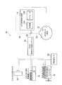
- FIG. 1 is a block diagram showing the configuration of the boil-off gas processing system according to the first embodiment of the present invention.
- the boil-off gas processing system 10 of this embodiment is mounted on a liquefied petroleum gas carrier ship that transports liquefied petroleum gas (LPG) containing a large amount of combustion gas components having a lower boiling point than propane, such as ethane, as cargo.
- LPG liquefied petroleum gas
- the liquefied petroleum gas to be transported contains, for example, 5 to 8 mol% or more of ethane in the liquid phase.
- the liquefied petroleum gas carrier ship equipped with the boil-off gas processing system 10 of the first embodiment can load liquefied petroleum gas (LPG) in one or more cargo tanks (LPG tanks) 12.
- the boil-off gas processing system 10 includes a well-known LPG re-liquefaction device 14 capable of re-liquefying propane contained in the boil-off gas (BOG) of liquefied petroleum gas generated in the cargo tank 12 by approximately 100%.
- the gas liquefied by the LPG reliquefaction device 14 is returned to the cargo tank 12 using a pump or the like (not shown).
- the liquefied gas carrier employs, for example, a dual-fuel low-speed diesel engine as the main engine 16 as a device capable of producing ethane gas, and a generator capable of dual-fuel generation that uses ethane gas.
- the engine 18 and the boiler 20 are provided. That is, when the boil-off gas that can be used as fuel is small, fuel such as heavy oil stored in the fuel oil tank 22 is supplied to the main engine 16, the generator engine 18, and the boiler 20.
- the boil-off gas processing system 10 further supplies boil-off gas to some or all of the equipment capable of producing ethane gas such as the main engine 16, the generator engine 18 and the boiler 20 from a part of the boil-off gas accumulated above the cargo tank 12.
- a fuel gas supply system (FGSS) 24 is provided.
- FGSS fuel gas supply system
- propane a gas having a relatively high boiling point
- propane is reliquefied and returned to the cargo tank 12 by the LPG reliquefaction device 14
- the boil-off gas accumulated in the upper part of the cargo tank 12 has a relatively low boiling point such as ethane.
- the gas concentration increases. For example, when the ethane concentration in the boil-off gas accumulated in the cargo tank 12 exceeds a predetermined value, the fuel gas supply system 24 supplies the boil-off gas to the main engine 16, the generator engine 18, the boiler 20, and the like.
- the boil-off gas processing system of the first embodiment can effectively use boil-off gas containing a large amount of ethane as fuel.
- FIG. 2 is a block diagram showing the configuration of the boil-off gas processing system of the second embodiment.
- the boil-off gas processing system 30 of the second embodiment is obtained by adding a piping path capable of supplying gas from the LPG reliquefaction device 14 to the fuel gas supply system 24 to the boil-off gas processing system 10 of the first embodiment.
- the configuration is substantially the same as that of the first embodiment, and the description of the same configuration is omitted by using the same reference numerals.
- the LPG reliquefaction device 14 includes a compressor 14A at the front stage and a separator 14B at the rear stage. That is, the high-pressure and high-temperature boil-off gas compressed by the compressor 14A is sent to the separator 14B through a condenser and an expansion valve using a refrigerant such as seawater (not shown) in the middle stage, and is separated into a liquid phase and a gas phase in the separator 14B. Is done.
- the liquid phase component of the separator 14B is substantially propane (or butane), and is returned to the cargo tank 12 using a pump or the like.
- a pipe path 26 for supplying the gas separated in the separator 14B to the fuel gas supply system 24 is connected to the separator 14B.
- the piping path 26 and the piping path 25 for supplying the boil-off gas from the cargo tank 12 to the fuel gas supply system 24 can be switched by a switching valve 28, and the gas supplied to the fuel gas supply system 24 is switched by the switching valve 28. It is alternatively switched between the piping path 25 and the piping path 26.
- the boil-off gas can be supplied as fuel because the ethane content of the boil-off gas initially stored in the cargo tank 12 is relatively high.
- the concentration of ethane in the cargo tank 12 in the liquid phase is about 10 mol%
- the temperature in the tank needs to be about ⁇ 52 ° C. in order to maintain the liquefied petroleum gas in a liquid state.
- the ethane is preferentially used as fuel from the boil-off gas accumulated in the cargo tank 12
- the ethane content in the cargo tank 12 decreases with the passage of time.
- the fuel gas supply system is connected between the piping paths 25 and 26 accordingly. And stably supply high purity ethane to the main engine 16, the generator engine 18, the boiler 20, and the like.
- the cargo tank has been described as an example, but the tank may be a tank other than the cargo tank.
- Boil-off gas treatment system 12 Cargo tank (LPG tank) 14 LPG reliquefaction device 14A Compressor 14B Separator 16 Main engine 18 Generator engine 20 Boiler 22 Fuel oil tank 24 Fuel gas supply system (FGSS) 25, 26 Piping route
Landscapes
- Engineering & Computer Science (AREA)
- Mechanical Engineering (AREA)
- General Engineering & Computer Science (AREA)
- Chemical & Material Sciences (AREA)
- Chemical Kinetics & Catalysis (AREA)
- General Chemical & Material Sciences (AREA)
- Oil, Petroleum & Natural Gas (AREA)
- Combustion & Propulsion (AREA)
- Filling Or Discharging Of Gas Storage Vessels (AREA)
Abstract
カーゴタンク12内に液化石油ガスを貯蔵する。カーゴタンク12内で発生したボイルオフガスのプロパンを再液化するためのLPG用再液化装置14を設ける。LPG用再液化装置14で再液化されたガスをポンプ等を用いてカーゴタンク12内へと戻す。LPG用再液化装置14で再液化されないカーゴタンク12内のボイルオフガスをガス焚き可能な主機関16、発電機エンジン18、ボイラ20の何れかまたは全てに供給する燃料ガス供給システム24を設ける。
Description
本発明は、液化石油ガスが荷載されるカーゴタンクで発生するボイルオフガス(BOG)を処理するシステムに関する。
液化石油ガス(LPG)を運搬する液化石油ガス(LPG)運搬船では、カーゴタンクで発生するボイルオフガス(BOG)を再液化装置で液化し、カーゴタンクに戻している。液化石油ガス(LPG)の主成分はプロパンやブタンであり、液化石油ガス運搬船に搭載される再液化装置は、ボイルオフガス中の主成分であるプロパンガスを100%液化できるように設計されている。しかし、液化石油ガスには、エタンなどの成分も僅かに含まれ、エタンの沸点は-89℃とプロパンの沸点-42℃に比べてかなり低いため、プロパンに合わせた再液化装置では、ボイルオフガスに含まれるエタンガスを全量液化することはできない。そのためこのような再液化装置が搭載された従来の液化石油ガス運搬船では、エタン成分は一部ガスとして残留してしまい、液化しきれなかったエタンリッチなボイルオフガスは、大気中に放出され廃棄される。また、再液化装置の冷却能力を大きくし、エタンリッチなボイルオフガスも再液化しようとする場合、装置が大型化し必要な電力が増加することとなる。このような問題に対して、カーゴタンク内の液相から取り出したLPGによりボイルオフガスを冷却して、圧縮機や凝縮器の能力を上げることなく、エタンを含んだボイルオフガスを再液化する構成が提案されている(特許文献1参照)。
液化石油ガス(LPG)に含まれるエタンの割合は、石油ガス生産地によって異なる。これまで液化石油ガス運搬船で対象とされていた液化石油ガスに含まれるエタンの割合は液相において2.5mol%程度であり、特許文献1の構成でもエタンを含むボイルオフガスをそれなりに再液化することができた。しかし、近年注目される米国産の液化石油ガスの場合、他の産地に比べエタンの含有量が高く、例えば液相において8mol%程度も含まれる。このような液化石油ガスを運搬対象とする場合、特許文献1の構成では十分にエタンを再液化することができず、依然エタンリッチなボイルオフガスがカーゴタンク内に残留してしまう。
本発明は、エタンを多く含む液化石油ガスを運搬する液化石油ガス運搬船において、再液化装置を大型化することなくボイルオフガスを処理可能なシステムを提供することを目的としている。
本発明の液化石油ガス運搬船用のボイルオフガス処理システムは、液化石油ガスを貯蔵するタンク内で発生したボイルオフガスのプロパンを再液化するための再液化装置と、再液化装置で再液化されないタンク内のボイルオフガスをガス焚き可能な機器に供給する燃料ガス供給手段とを備えることを特徴としている。
ボイルオフガス処理システムは、再液化装置はセパレータを備え、セパレータに溜まるガスを燃料ガス供給手段へと供給する配管経路を備える。ボイルオフガス処理システムは更に、セパレータから燃料ガス供給手段にガスを供給する配管経路と、タンク内から燃料ガス供給手段にボイルオフガスを供給する配管経路との間で、供給経路を択一的に切り換える切換手段とを備える。切換手段はタンク内のボイルオフガス中のエタン濃度に基づいて供給経路の切り換えを行う。
本発明の液化石油ガス運搬船は、上記ボイルオフガス処理システムの何れかを備えたことを特徴としている。
本発明によれば、エタンを多く含む液化石油ガスを運搬する液化石油ガス運搬船において、再液化装置を大型化することなくボイルオフガスを処理可能なシステムを提供することができる。
以下、本発明の実施形態について添付図面を参照して説明する。
図1は、本発明の第1実施形態のボイルオフガス処理システムの構成を示すブロック図である。
図1は、本発明の第1実施形態のボイルオフガス処理システムの構成を示すブロック図である。
本実施形態のボイルオフガス処理システム10は、例えばエタンなどプロパンに比べ沸点が低い燃焼ガス成分が多く含まれる液化石油ガス(LPG)を貨物として運搬する液化石油ガス運搬船に搭載される。運搬対象とする液化石油ガスは、例えばエタンを液相において5mol%~8mol%、あるいはそれ以上含む。
第1実施形態のボイルオフガス処理システム10を搭載する液化石油ガス運搬船は、1以上のカーゴタンク(LPGタンク)12内に液化石油ガス(LPG)を積載可能である。ボイルオフガス処理システム10は、カーゴタンク12内で発生する液化石油ガスのボイルオフガス(BOG)に含まれるプロパンを略100%再液化可能な周知のLPG用再液化装置14を備える。LPG用再液化装置14で液化されたガスは、図示しないポンプ等を用いてカーゴタンク12内へと戻される。
液化ガス運搬船は、エタンガスを焚くことができる機器として、例えば主機関16に2元燃料焚き低速ディーゼル機関を採用し、その他にもエタンガスを用いたガス焚き可能である2元燃料焚き可能な発電機エンジン18やボイラ20などを備える。すなわち、燃料として使用できるボイルオフガスが少ないときには、燃料油タンク22に貯留される重油等の燃料が主機関16、発電機エンジン18、ボイラ20に供給される。
ボイルオフガス処理システム10は、更にカーゴタンク12の上方に溜まったボイルオフガスの一部を主機関16、発電機エンジン18、ボイラ20等のエタンガス焚き可能な機器の一部または全てにボイルオフガスを供給するための燃料ガス供給システム(FGSS)24を備える。LPG用再液化装置14によりプロパン等の沸点が相対的に高いガスのみが再液化されカーゴタンク12へ戻されると、カーゴタンク12の上部に溜まるボイルオフガスでは、沸点が相対的に低いエタン等のガスの濃度が上昇する。燃料ガス供給システム24は、例えばカーゴタンク12内に溜まったボイルオフガス中のエタン濃度が所定値を超えると、ボイルオフガスを主機関16、発電機エンジン18、ボイラ20等へ供給する。
以上のように、第1実施形態のボイルオフガス処理システムでは、エタンが多く含まれるボイルオフガスを燃料として有効に利用することができる。
図2は、第2実施形態のボイルオフガス処理システムの構成を示すブロック図である。第2実施形態のボイルオフガス処理システム30は、第1実施形態のボイルオフガス処理システム10に、LPG用再液化装置14から燃料ガス供給システム24へとガスを供給可能な配管経路を追加したものであり、その他の構成は略第1実施形態と同様であり、同様の構成に関しては同一参照符号を用いその説明を省略する。
LPG用再液化装置14は、前段に圧縮機14Aを備え、後段にセパレータ14Bを備える。すなわち、圧縮機14Aで圧縮された高圧高温のボイルオフガスは、中段の図示しない海水等の冷媒による凝縮器と膨張弁を経て、セパレータ14Bへと送り出され、セパレータ14Bにおいて液相と気相に分離される。セパレータ14Bの液相成分は略プロパン(またはブタン)であり、ポンプ等を利用してカーゴタンク12内へと戻される。
セパレータ14Bには、セパレータ14B内で分離されたガスを燃料ガス供給システム24へと供給する配管経路26が接続される。配管経路26とカーゴタンク12から燃料ガス供給システム24へとボイルオフガスを供給する配管経路25は、切換弁28により切換可能であり、燃料ガス供給システム24に供給されるガスは、切換弁28により配管経路25と配管経路26との間で択一的に切り換えられる。
液相において10mol%以上エタンを含む液化石油ガスの場合、カーゴタンク12内に当初溜まっているボイルオフガスのエタンの含有率は比較的高いためボイルオフガスを燃料として供給することが可能である。また、カーゴタンク12内のエタンの液相における濃度が10mol%程度の場合、液化石油ガスを液体状態に維持するにはタンク内の温度を約-52℃にする必要がある。しかし、カーゴタンク12内に溜まったボイルオフガスからエタンを優先的に燃料として使用する構成であると、時間の経過にともないカーゴタンク12内のエタン含有率は低下し、これによりカーゴタンク12内の温度が上昇してプロパンの沸点-42℃に近づく。そのため相対的にボイルオフガス内のプロパン含有量が増大しカーゴタンク12内のボイルオフガスをそのまま燃料として使用できなくなる。
第2実施形態では、セパレータ14Bからの配管経路26を設けることで、カーゴタンク12内のボイルオフガス中のエタンの含有率を検知し、それに応じて燃料ガス供給系統を配管経路25、26の間で切り替え、安定的に純度の高いエタンを主機関16、発電機エンジン18、ボイラ20等へ供給する。
以上のように第2実施形態のボイルオフガス処理システムにおいても第1実施形態と同様の効果を得ることができる。
なお、本実施形態ではカーゴタンクを例に説明を行なったが、タンクはカーゴタンク以外のタンクであってもよい。
10、30 ボイルオフガス処理システム
12 カーゴタンク(LPGタンク)
14 LPG用再液化装置
14A 圧縮機
14B セパレータ
16 主機関
18 発電機エンジン
20 ボイラ
22 燃料油タンク
24 燃料ガス供給システム(FGSS)
25、26 配管経路
12 カーゴタンク(LPGタンク)
14 LPG用再液化装置
14A 圧縮機
14B セパレータ
16 主機関
18 発電機エンジン
20 ボイラ
22 燃料油タンク
24 燃料ガス供給システム(FGSS)
25、26 配管経路
Claims (5)
- 液化石油ガスを貯蔵するタンク内で発生したボイルオフガスのプロパンを再液化するための再液化装置と、
前記再液化装置で再液化されない前記タンク内の前記ボイルオフガスをガス焚き可能な機器に供給する燃料ガス供給手段と
を備えることを特徴とする液化石油ガス運搬船用のボイルオフガス処理システム。 - 前記再液化装置がセパレータを備え、前記セパレータに溜まるガスを前記燃料ガス供給手段へと供給する配管経路を備えることを特徴とする請求項1に記載のボイルオフガス処理システム。
- 前記セパレータから前記燃料ガス供給手段にガスを供給する配管経路と、前記タンク内から前記燃料ガス供給手段にボイルオフガスを供給する配管経路との間で、供給経路を択一的に切り換える切換手段とを備えることを特徴とする請求項2に記載のボイルオフガス処理システム。
- 前記切換手段が前記タンク内のボイルオフガス中のエタン濃度に基づいて前記供給経路の切り換えを行うことを特徴とする請求項3に記載のボイルオフガス処理システム。
- 請求項1~4の何れか一項に記載のボイルオフガス処理システムを備えたことを特徴とする液化石油ガス運搬船。
Applications Claiming Priority (2)
| Application Number | Priority Date | Filing Date | Title |
|---|---|---|---|
| JP2016145713A JP2018017133A (ja) | 2016-07-25 | 2016-07-25 | 液化石油ガス運搬船用ボイルオフガス処理システム |
| JP2016-145713 | 2016-07-25 |
Publications (1)
| Publication Number | Publication Date |
|---|---|
| WO2018021095A1 true WO2018021095A1 (ja) | 2018-02-01 |
Family
ID=61016849
Family Applications (1)
| Application Number | Title | Priority Date | Filing Date |
|---|---|---|---|
| PCT/JP2017/025971 Ceased WO2018021095A1 (ja) | 2016-07-25 | 2017-07-18 | 液化石油ガス運搬船用ボイルオフガス処理システム |
Country Status (2)
| Country | Link |
|---|---|
| JP (1) | JP2018017133A (ja) |
| WO (1) | WO2018021095A1 (ja) |
Citations (3)
| Publication number | Priority date | Publication date | Assignee | Title |
|---|---|---|---|---|
| JPS59165554U (ja) * | 1983-04-22 | 1984-11-06 | 三井造船株式会社 | ガス焚きデイ−ゼル機関のガス供給装置 |
| JP2005273681A (ja) * | 2004-03-22 | 2005-10-06 | Ebara Corp | 低温液化ガス貯留システム |
| JP2012233534A (ja) * | 2011-05-02 | 2012-11-29 | Ihi Marine United Inc | ボイルオフガス処理装置及び液化ガスタンク |
-
2016
- 2016-07-25 JP JP2016145713A patent/JP2018017133A/ja active Pending
-
2017
- 2017-07-18 WO PCT/JP2017/025971 patent/WO2018021095A1/ja not_active Ceased
Patent Citations (3)
| Publication number | Priority date | Publication date | Assignee | Title |
|---|---|---|---|---|
| JPS59165554U (ja) * | 1983-04-22 | 1984-11-06 | 三井造船株式会社 | ガス焚きデイ−ゼル機関のガス供給装置 |
| JP2005273681A (ja) * | 2004-03-22 | 2005-10-06 | Ebara Corp | 低温液化ガス貯留システム |
| JP2012233534A (ja) * | 2011-05-02 | 2012-11-29 | Ihi Marine United Inc | ボイルオフガス処理装置及び液化ガスタンク |
Also Published As
| Publication number | Publication date |
|---|---|
| JP2018017133A (ja) | 2018-02-01 |
Similar Documents
| Publication | Publication Date | Title |
|---|---|---|
| KR101386543B1 (ko) | 선박의 증발가스 처리 시스템 | |
| KR101356003B1 (ko) | 선박의 증발가스 처리 시스템 | |
| KR101559403B1 (ko) | 재액화 전력 소비량을 절감하기 위한 증발가스 처리장치 및방법 | |
| CN107735561B (zh) | 燃气供给系统 | |
| EP3437980A1 (en) | Boil-off gas re-liquefying device and method for ship | |
| KR102153624B1 (ko) | 선박의 증발가스 처리 시스템 및 방법 | |
| KR102189792B1 (ko) | 액화연료 추진선박의 재액화시스템 | |
| KR101164087B1 (ko) | 재액화 전력 소비량을 절감하기 위한 증발가스 처리장치 및 방법 | |
| KR101711955B1 (ko) | 연료가스 공급시스템 | |
| KR20110046946A (ko) | 고압가스 분사엔진과 저압가스 분사엔진을 갖는 액화연료가스 추진 선박에 연료가스를 공급하는 시스템 | |
| KR101519537B1 (ko) | 선박의 증발가스 처리 시스템 | |
| KR20170066737A (ko) | 연료가스 공급시스템 | |
| CN109070977B (zh) | 船只以及汽化气体再液化方法 | |
| KR101763677B1 (ko) | 재액화 시스템 | |
| KR101788749B1 (ko) | 증발가스 처리 시스템 및 방법 | |
| KR20200075199A (ko) | 선박의 연료공급시스템 및 방법 | |
| KR102387177B1 (ko) | 증발가스 처리 장치 및 방법 | |
| KR101722369B1 (ko) | 연료가스 공급시스템 | |
| KR20160070346A (ko) | 선박의 증발가스 처리 시스템 및 방법 | |
| KR102499810B1 (ko) | 선박의 증발가스 처리 시스템 및 방법 | |
| KR101788753B1 (ko) | 선박의 증발가스 처리 시스템 및 방법 | |
| KR102372752B1 (ko) | 부유식 액화천연가스 생산설비의 선외 전기 공급 장치 및 방법 | |
| KR101606562B1 (ko) | 증발가스 처리장치 및 방법 | |
| KR20110046945A (ko) | 고압가스 분사엔진과 저압가스 분사엔진을 갖는 액화연료가스 추진 선박에 연료가스를 공급하는 시스템 | |
| KR101852132B1 (ko) | 액화천연가스 공급 시스템 |
Legal Events
| Date | Code | Title | Description |
|---|---|---|---|
| 121 | Ep: the epo has been informed by wipo that ep was designated in this application |
Ref document number: 17834103 Country of ref document: EP Kind code of ref document: A1 |
|
| NENP | Non-entry into the national phase |
Ref country code: DE |
|
| 122 | Ep: pct application non-entry in european phase |
Ref document number: 17834103 Country of ref document: EP Kind code of ref document: A1 |