WO2018020900A1 - 端末装置、基地局、方法及び記録媒体 - Google Patents
端末装置、基地局、方法及び記録媒体 Download PDFInfo
- Publication number
- WO2018020900A1 WO2018020900A1 PCT/JP2017/022400 JP2017022400W WO2018020900A1 WO 2018020900 A1 WO2018020900 A1 WO 2018020900A1 JP 2017022400 W JP2017022400 W JP 2017022400W WO 2018020900 A1 WO2018020900 A1 WO 2018020900A1
- Authority
- WO
- WIPO (PCT)
- Prior art keywords
- base station
- enb
- quality information
- terminal device
- control unit
- Prior art date
- Legal status (The legal status is an assumption and is not a legal conclusion. Google has not performed a legal analysis and makes no representation as to the accuracy of the status listed.)
- Ceased
Links
Images


Classifications
-
- H—ELECTRICITY
- H04—ELECTRIC COMMUNICATION TECHNIQUE
- H04B—TRANSMISSION
- H04B7/00—Radio transmission systems, i.e. using radiation field
- H04B7/02—Diversity systems; Multi-antenna system, i.e. transmission or reception using multiple antennas
- H04B7/04—Diversity systems; Multi-antenna system, i.e. transmission or reception using multiple antennas using two or more spaced independent antennas
- H04B7/06—Diversity systems; Multi-antenna system, i.e. transmission or reception using multiple antennas using two or more spaced independent antennas at the transmitting station
- H04B7/0613—Diversity systems; Multi-antenna system, i.e. transmission or reception using multiple antennas using two or more spaced independent antennas at the transmitting station using simultaneous transmission
- H04B7/0615—Diversity systems; Multi-antenna system, i.e. transmission or reception using multiple antennas using two or more spaced independent antennas at the transmitting station using simultaneous transmission of weighted versions of same signal
- H04B7/0619—Diversity systems; Multi-antenna system, i.e. transmission or reception using multiple antennas using two or more spaced independent antennas at the transmitting station using simultaneous transmission of weighted versions of same signal using feedback from receiving side
- H04B7/0621—Feedback content
- H04B7/063—Parameters other than those covered in groups H04B7/0623 - H04B7/0634, e.g. channel matrix rank or transmit mode selection
-
- H—ELECTRICITY
- H04—ELECTRIC COMMUNICATION TECHNIQUE
- H04B—TRANSMISSION
- H04B7/00—Radio transmission systems, i.e. using radiation field
- H04B7/02—Diversity systems; Multi-antenna system, i.e. transmission or reception using multiple antennas
- H04B7/04—Diversity systems; Multi-antenna system, i.e. transmission or reception using multiple antennas using two or more spaced independent antennas
- H04B7/06—Diversity systems; Multi-antenna system, i.e. transmission or reception using multiple antennas using two or more spaced independent antennas at the transmitting station
- H04B7/0613—Diversity systems; Multi-antenna system, i.e. transmission or reception using multiple antennas using two or more spaced independent antennas at the transmitting station using simultaneous transmission
- H04B7/0615—Diversity systems; Multi-antenna system, i.e. transmission or reception using multiple antennas using two or more spaced independent antennas at the transmitting station using simultaneous transmission of weighted versions of same signal
- H04B7/0617—Diversity systems; Multi-antenna system, i.e. transmission or reception using multiple antennas using two or more spaced independent antennas at the transmitting station using simultaneous transmission of weighted versions of same signal for beam forming
-
- H—ELECTRICITY
- H04—ELECTRIC COMMUNICATION TECHNIQUE
- H04B—TRANSMISSION
- H04B17/00—Monitoring; Testing
- H04B17/30—Monitoring; Testing of propagation channels
- H04B17/309—Measuring or estimating channel quality parameters
-
- H—ELECTRICITY
- H04—ELECTRIC COMMUNICATION TECHNIQUE
- H04B—TRANSMISSION
- H04B7/00—Radio transmission systems, i.e. using radiation field
- H04B7/02—Diversity systems; Multi-antenna system, i.e. transmission or reception using multiple antennas
- H04B7/04—Diversity systems; Multi-antenna system, i.e. transmission or reception using multiple antennas using two or more spaced independent antennas
- H04B7/06—Diversity systems; Multi-antenna system, i.e. transmission or reception using multiple antennas using two or more spaced independent antennas at the transmitting station
- H04B7/0613—Diversity systems; Multi-antenna system, i.e. transmission or reception using multiple antennas using two or more spaced independent antennas at the transmitting station using simultaneous transmission
- H04B7/0615—Diversity systems; Multi-antenna system, i.e. transmission or reception using multiple antennas using two or more spaced independent antennas at the transmitting station using simultaneous transmission of weighted versions of same signal
- H04B7/0619—Diversity systems; Multi-antenna system, i.e. transmission or reception using multiple antennas using two or more spaced independent antennas at the transmitting station using simultaneous transmission of weighted versions of same signal using feedback from receiving side
- H04B7/0621—Feedback content
- H04B7/0632—Channel quality parameters, e.g. channel quality indicator [CQI]
-
- H—ELECTRICITY
- H04—ELECTRIC COMMUNICATION TECHNIQUE
- H04B—TRANSMISSION
- H04B7/00—Radio transmission systems, i.e. using radiation field
- H04B7/02—Diversity systems; Multi-antenna system, i.e. transmission or reception using multiple antennas
- H04B7/04—Diversity systems; Multi-antenna system, i.e. transmission or reception using multiple antennas using two or more spaced independent antennas
- H04B7/06—Diversity systems; Multi-antenna system, i.e. transmission or reception using multiple antennas using two or more spaced independent antennas at the transmitting station
- H04B7/0686—Hybrid systems, i.e. switching and simultaneous transmission
- H04B7/0695—Hybrid systems, i.e. switching and simultaneous transmission using beam selection
- H04B7/06952—Selecting one or more beams from a plurality of beams, e.g. beam training, management or sweeping
- H04B7/06966—Selecting one or more beams from a plurality of beams, e.g. beam training, management or sweeping using beam correspondence; using channel reciprocity, e.g. downlink beam training based on uplink sounding reference signal [SRS]
-
- H—ELECTRICITY
- H04—ELECTRIC COMMUNICATION TECHNIQUE
- H04B—TRANSMISSION
- H04B7/00—Radio transmission systems, i.e. using radiation field
- H04B7/02—Diversity systems; Multi-antenna system, i.e. transmission or reception using multiple antennas
- H04B7/04—Diversity systems; Multi-antenna system, i.e. transmission or reception using multiple antennas using two or more spaced independent antennas
- H04B7/08—Diversity systems; Multi-antenna system, i.e. transmission or reception using multiple antennas using two or more spaced independent antennas at the receiving station
- H04B7/0868—Hybrid systems, i.e. switching and combining
- H04B7/088—Hybrid systems, i.e. switching and combining using beam selection
-
- H—ELECTRICITY
- H04—ELECTRIC COMMUNICATION TECHNIQUE
- H04W—WIRELESS COMMUNICATION NETWORKS
- H04W16/00—Network planning, e.g. coverage or traffic planning tools; Network deployment, e.g. resource partitioning or cells structures
- H04W16/24—Cell structures
- H04W16/28—Cell structures using beam steering
-
- H—ELECTRICITY
- H04—ELECTRIC COMMUNICATION TECHNIQUE
- H04W—WIRELESS COMMUNICATION NETWORKS
- H04W24/00—Supervisory, monitoring or testing arrangements
- H04W24/10—Scheduling measurement reports ; Arrangements for measurement reports
-
- H—ELECTRICITY
- H04—ELECTRIC COMMUNICATION TECHNIQUE
- H04W—WIRELESS COMMUNICATION NETWORKS
- H04W36/00—Hand-off or reselection arrangements
- H04W36/0005—Control or signalling for completing the hand-off
- H04W36/0055—Transmission or use of information for re-establishing the radio link
- H04W36/0058—Transmission of hand-off measurement information, e.g. measurement reports
-
- H—ELECTRICITY
- H04—ELECTRIC COMMUNICATION TECHNIQUE
- H04W—WIRELESS COMMUNICATION NETWORKS
- H04W36/00—Hand-off or reselection arrangements
- H04W36/24—Reselection being triggered by specific parameters
- H04W36/30—Reselection being triggered by specific parameters by measured or perceived connection quality data
-
- H—ELECTRICITY
- H04—ELECTRIC COMMUNICATION TECHNIQUE
- H04W—WIRELESS COMMUNICATION NETWORKS
- H04W48/00—Access restriction; Network selection; Access point selection
- H04W48/16—Discovering, processing access restriction or access information
-
- H—ELECTRICITY
- H04—ELECTRIC COMMUNICATION TECHNIQUE
- H04W—WIRELESS COMMUNICATION NETWORKS
- H04W48/00—Access restriction; Network selection; Access point selection
- H04W48/20—Selecting an access point
-
- H—ELECTRICITY
- H04—ELECTRIC COMMUNICATION TECHNIQUE
- H04W—WIRELESS COMMUNICATION NETWORKS
- H04W76/00—Connection management
- H04W76/20—Manipulation of established connections
- H04W76/25—Maintenance of established connections
-
- H—ELECTRICITY
- H04—ELECTRIC COMMUNICATION TECHNIQUE
- H04W—WIRELESS COMMUNICATION NETWORKS
- H04W72/00—Local resource management
- H04W72/20—Control channels or signalling for resource management
- H04W72/23—Control channels or signalling for resource management in the downlink direction of a wireless link, i.e. towards a terminal
Definitions
- the present disclosure relates to a terminal device, a base station, a method, and a recording medium.
- 5G Next Generation Communication Standard
- NR New Radio Access Technology
- MIMO multiple-input and multiple-output
- MIMO is a technique for performing beam forming using a plurality of antennas, and includes 3D (or Full Dimension) -MIMO capable of beam forming in a three-dimensional direction, Massive-MIMO using many antennas, and the like.
- 3D or Full Dimension
- Massive-MIMO using many antennas and the like.
- Patent Document 1 discloses a technique for determining a beam for a user apparatus based on feedback information from the user apparatus regarding beam forming.
- a communication unit that communicates with a base station that forms and communicates with a beam, and a downlink signal that is transmitted from the base station using a beam is used to transmit the downlink signal.
- a control unit that acquires quality information indicating the quality related to the direction of the received beam.
- a communication unit that forms a beam and communicates with a terminal device, setting information for causing the terminal device to acquire quality information indicating quality related to a beam direction, and the quality information And a control unit that notifies the apparatus.
- communication with a base station that forms and communicates with a beam, and reception of a downlink signal transmitted using the beam from the base station enables transmission of the downlink signal.
- communication with a terminal apparatus by forming a beam setting information for causing the terminal apparatus to acquire quality information indicating quality related to a beam direction, and the quality information by the processor Informing the terminal device.
- the downlink is transmitted by receiving a downlink signal transmitted from the base station using a beam, and a communication unit that communicates with a base station that forms a beam and communicates with the computer.
- a control unit that acquires quality information indicating the quality related to the direction of the beam used for signal transmission, and a recording medium on which a program for functioning is recorded.
- a communication unit that forms a beam and communicates with a terminal device, a setting information for causing the terminal device to acquire quality information indicating quality regarding a beam direction, and the quality information And a recording medium recording a program for causing the terminal device to function as a control unit.
- a mechanism capable of evaluating beam quality in an environment where beam tracking is provided is provided. Note that the above effects are not necessarily limited, and any of the effects shown in the present specification, or other effects that can be grasped from the present specification, together with or in place of the above effects. May be played.
- FIG. 2 is a diagram for describing an example of a configuration of a system according to an embodiment of the present disclosure.
- FIG. It is a figure for demonstrating the consideration regarding beam tracking. It is a sequence diagram which shows an example of the flow of the beam tracking procedure based on beamformed CSI-RS. It is a sequence diagram which shows an example of the flow of the beam tracking procedure based on SRS. It is a figure for demonstrating an example of the format of SRS in LTE. It is a figure for demonstrating narrowband SRS in LTE. It is a figure for demonstrating the beam selection using SRS and beamformed CSI-RS. It is a figure for demonstrating the beam selection using SRS and beamformed CSI-RS.
- elements having substantially the same functional configuration may be distinguished by adding different alphabets after the same reference numerals.
- a plurality of elements having substantially the same functional configuration are differentiated as necessary, such as base stations 100A, 100B, and 100C.
- base stations 100A, 100B, and 100C when there is no need to particularly distinguish each of a plurality of elements having substantially the same functional configuration, only the same reference numerals are given.
- the base stations 100A, 100B, and 100C they are simply referred to as the base station 100.
- FIG. 1 is a diagram for explaining an example of a system configuration according to the present embodiment.
- the system 1 according to the present embodiment includes a base station 100 and a terminal device 200.
- the base station 100 is a device that operates the cell 11 and provides a wireless communication service to the terminal device 200 in the cell 11.
- a plurality of base stations 100 may exist, and the base stations 100A to 100C operate the cells 11A to 11C, respectively, and provide wireless communication services to the terminal devices 200A to 200C, respectively.
- the base stations 100A and 100B are small cell base stations, and the cells 11A and 11B are small cells.
- the base station 100C is a macro cell base station, and the cell 11C is a macro cell.
- the macro cell base station 100C has a function of cooperatively controlling wireless communication by the managed small cell base stations 100A and 100B.
- the base stations 100 are communicably connected, and are connected by, for example, an X2 interface. Further, the base station 100 and the core network 12 are connected so as to be communicable, and are connected by, for example, an S1 interface.
- the terminal device 200 is a device that communicates with the base station 100.
- the terminal device 200 typically has high mobility, and cell selection corresponding to movement is performed.
- beam tracking for forming and communicating an appropriate beam according to the movement of the terminal device 200 is performed.
- the base station may be referred to as an eNB (evolved Node B) below. This does not limit the base station 100 to be operated by the radio access technology in LTE, and can be operated by the 5G radio access technology. That is, the base station may be called other than eNB.
- the terminal device may be referred to as a UE (User Equipment) or a user in the following, but this is not limited to the terminal device 200 being operated by the radio access technology in LTE, and 5G wireless It can be operated by access technology.
- the core network 12 includes a control node that controls the base station 100.
- the core network 12 may include, for example, EPC (Evolved Packet Core) or may include a 5G architecture.
- the core network 12 is connected to the packet data network via a gateway device.
- FIG. 2 is a diagram for explaining the consideration regarding beam tracking. As shown in FIG. 2, it is desirable to follow the beam formed by the eNB according to the movement of the UE.
- Codebook base beam forming In LTE, it is unlikely that a mechanism that changes the beam steplessly and recreates the beam following the UE is employed. This is because a calculation cost for recreating a new beam occurs. Therefore, a mechanism for pre-forming beams in all directions from the eNB and selecting and providing a beam to be used for communication with the UE from the pre-formed beams is provided by 3GPP Release 13 Adopted for FD-MIMO (full dimension multi input multi output). Such a mechanism is also referred to as codebook based beam forming.
- 360 beams are prepared.
- 720 beams are prepared.
- 360 beams for 180 degrees are prepared.
- beam tracking means that a beam suitable for communication with the UE is continuously selected from beams prepared in advance as a codebook.
- Beam tracking based on downlink reference signal In 3GPP RAN1 Release 13 FD-MIMO, the beam selection was studied. In the examination, it was considered that the eNB selects a beam suitable for communication with the UE based on a downlink beamformed reference signal (RS). Such a downlink reference signal is also referred to as a beamformed CSI-RS (channel state information-reference signal).
- RS downlink beamformed reference signal
- Such a downlink reference signal is also referred to as a beamformed CSI-RS (channel state information-reference signal).
- the eNB provides a plurality of beamformed CSI-RS (multiple beamformed CSI-RS), and performs communication with the UE using a beam according to a reception result in the UE.
- CSI-RS channel state information-reference signal
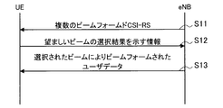
- FIG. 3 is a sequence diagram showing an example of a flow of a beam tracking procedure based on the beamformed CSI-RS.
- the eNB transmits a plurality of beamformed CSI-RSs using a plurality of beams (step S11).
- the UE selects a desired beam from among the plurality of beams used for transmission of the beamformed CSI-RS based on the provided reception results of the plurality of beamformed CSI-RSs.
- the information shown is transmitted to eNB (step S12).
- the information indicating the selection result includes identification information (typically, a beam number) of a desired beam.
- the UE selects one or more desired beams based on the received power of each beam.
- the eNB provides user data beamformed by the selected beam to the UE (step S13).
- the tracking capability varies depending on how often a plurality of beamformed CSI-RS sets are provided to the UE. For example, when provided every 100 ms, tracking will be performed with a granularity of 100 ms. If the UE is moving at a speed that stays in the beam for 100 ms, tracking with this granularity is sufficient, but if the UE speed increases, for example, tracking with a granularity of 5 ms or less is required. Also come out. In such a case, the overhead of downlink resources for providing a set of a plurality of beamformed CSI-RSs becomes large, so that efficient communication becomes difficult.
- the eNB typically determines which beam to use to transmit the above-described plurality of beamformed CSI-RSs based on the uplink reference signal.
- the eNB knows the approximate position of the UE based on the uplink reference signal, selects a plurality of beam candidates appropriate for the UE, and uses the plurality of selected beam candidates to generate a plurality of beamformed CSIs.
- -Send RS This uplink reference signal is also referred to as SRS (Sounding Reference Signal).
- SRS Sounding Reference Signal
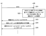
- FIG. 4 is a sequence diagram showing an example of a flow of a beam tracking procedure based on SRS.
- the UE transmits an SRS to the eNB (step S21).
- the eNB acquires channel information between the UE and the eNB based on the reception result of the SRS, and selects a plurality of beams to be used for transmission of a plurality of beamformed CSI-RSs based on the channel information ( Step S22).
- steps S23 to S25 processing similar to the processing related to steps S11 to S13 described above with reference to FIG. 3 is performed.
- step S21 it can be said that eNB can acquire (accurately, estimate) downlink channel information based on SRS only in the case of TDD.
- SRS> The main purpose of SRS is that the eNB acquires uplink channel information in the operating frequency bandwidth (that is, bandwidth) and uses it for downlink scheduling rather than the beam selection described above.
- Scheduling means that the eNB determines which part of the downlink or uplink resource (unit resource separated by frequency and time) the UE uses, and notifies the UE of the determined content.
- the resource block includes 12 subcarriers arranged at intervals of 15 kHz, and 100 resource blocks are spread in 20 MHz.
- the resources of the 100 resource blocks are shared by a plurality of UEs. That is, FDM (Frequency Division Multiplexing) is performed. Therefore, it can be said that it is eNB scheduling to determine which part of 20 MHz is used by the UE.
- FDM Frequency Division Multiplexing
- ENB achieves the main purpose described above based on SRS. Specifically, the eNB acquires uplink channel information based on the reception result of the SRS, estimates downlink channel information based on the acquired channel information, and performs scheduling based on the estimated downlink channel information. Do.
- Such an existing SRS designed for the main purpose of scheduling is not suitable as a reference signal for beam selection.
- channel information over the entire channel is not necessarily required for beam tracking.
- FIG. 5 is a diagram for explaining an example of an SRS format in LTE.
- the LTE uplink is operated by SC-FDMA (Single Carrier Frequency Division Multiple Access), and includes 14 symbols per subframe.
- the symbols in the time direction in the uplink are also referred to as SC-FDMA symbols or OFDM symbols.
- the SRS is transmitted using the last OFDM symbol.
- the SRS is not necessarily transmitted using the last OFDM symbol in all subframes.
- PUSCH Physical Uplink Shared Channel
- PUCCH Physical Uplink Control Channel
- the SRS may occupy all of the operating bandwidth and may be transmitted at once. On the other hand, a part of the operated bandwidth may be used in one transmission of SRS.
- the former is also referred to as a broadband SRS, and the latter is also referred to as a narrow band SRS.
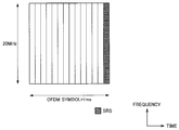
- FIG. 6 is a diagram for explaining narrow band SRS in LTE.
- a narrow band SRS uses a part of the bandwidth in one transmission.
- the SRS is transmitted over the entire bandwidth to be operated.
- the merit of narrowband SRS is that the UE can use more power for one SRS transmission, so that the uplink coverage of SRS can be increased.
- the merit of narrowband SRS is that the quality of SRS received by the eNB can be improved.
- both wideband and narrowband SRS are designed mainly to acquire channel information of the entire bandwidth to be operated.
- the target bandwidth of both the wideband and narrowband SRS is the entire bandwidth operated by the eNB.
- the eNB may be configured in the UE to transmit SRS periodically or aperiodic.
- ENB sets semi-static using RRC (Radio Resource Control) signaling when setting periodic SRS. Accordingly, it is difficult to dynamically change the transmission cycle, for example, regarding periodic transmission.
- RRC Radio Resource Control
- the eNB transmits an SRS request aperiodically as necessary, and the UE returns the SRS when receiving the SRS request.
- the aperiodic SRS is not appropriate as a reference signal for periodically selecting a beam for beam tracking. This is because the downlink SRS request becomes an overhead.
- the eNB provides a plurality of beamformed reference signals, and uses the beam according to the reception result at the UE to communicate with the UE. It is conceivable to perform communication. In that case, as described above with reference to FIG. 4, the eNB may determine which beam to use to transmit a plurality of beamformed reference signals based on the SRS. This is because the eNB can roughly grasp the direction of the UE based on the reception result of the SRS.
- the SRS can be used for beam selection provided to the UE.
- the SRS is an uplink reference signal, it is difficult for the eNB to know the situation of downlink interference based on the reception result of the SRS. Therefore, the final beam selection is preferably determined by the UE based on the downlink reference signal.
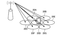
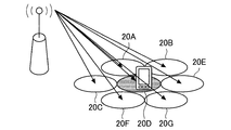
- FIGS. 7 and 8 are diagrams for explaining beam selection using SRS and beamformed CSI-RS.
- the eNB grasps the rough position of the UE based on the SRS and selects a plurality of beam candidates appropriate for the UE. Then, as illustrated in FIG. 7, the eNB transmits a plurality of beamformed CSI-RSs using the selected plurality of beam candidates. In the example shown in FIG. 7, a plurality of beamformed CSI-RSs are transmitted to the areas 20A to 20G, and the UE is included in the center area 20D. That is, a plurality of beamformed CSI-RSs roughly grasp the UE.
- the UE selects one or more desired beams from among the plurality of beams used for transmission of the beamformed CSI-RS based on the received results of the plurality of beamformed CSI-RS provided.
- the information indicating the selection result is transmitted to the eNB.
- the UE selects a beam addressed to the area 20D.
- eNB selects the beam suitable for UE based on the information which shows the selection result of a beam.
- the eNB selects a beam addressed to the area 20D based on feedback from the UE.
- the UE is stationary without moving at all.
- beam selection for beam tracking is easy.
- the beam selection may be performed again due to the influence of the surrounding environment, for example, shielding of the beam (hereinafter also referred to as blocking) due to a shielding object such as a car or a person crossing between the eNB and the UE. Sometimes it is done.
- the UE moves at high speed.
- the beam tracking is difficult. If the beam provided to the UE is sharp, the difficulty of beam tracking becomes even higher. For example, when a beam having a width of 1 degree is provided, the difficulty level is higher than when a beam having a width of 10 degrees is provided. This is because the sharper the beam, the shorter the time required for the UE to move within the range included in the beam.
- Non-continuous channel environment changes may occur, for example, when a shield suddenly enters between an eNB and a UE, and when a UE with a planar antenna is rotating rapidly. In such cases, the appropriate beam for the UE may change. In addition, a beam that is reflected and indirectly reaches the UE may be more appropriate than a beam that directly reaches the UE.
- a UE receives a downlink reference signal (for example, CSI-RS) transmitted by an eNB through a non-directional antenna and receives received power (for example, RSRP ( Reference Signal Received Power) was measured, and the destination eNB was selected based on the measurement result, even though the UE was already connected to the eNB and communicating. To search for a desired eNB.
- CSI-RS downlink reference signal
- RSRP Reference Signal Received Power
- the quality of the downlink provided from the connected eNB ie, the serving eNB
- the serving eNB ie, the measurement result of the received power of the downlink reference signal
- the UE decides to hand over to the other eNB (that is, the target eNB), and notifies the serving eNB of the desire. Then, a handover decision as to whether or not to allow handover is performed in the serving eNB, and if permitted, the UE hands over to the target eNB.
- the eNB can perform beam selection (ie, beam tracking) so as to follow the beam according to the movement of the UE.
- beam selection ie, beam tracking
- the UE can grasp the timing for handover to another eNB. This is because the serving eNB can provide good downlink quality even at the cell edge when a beam having a sharp directivity is followed according to the movement of the UE.
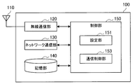
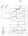
- FIG. 9 is a block diagram illustrating an example of the configuration of the base station 100 according to the present embodiment.
- the base station 100 includes an antenna unit 110, a radio communication unit 120, a network communication unit 130, a storage unit 140, and a control unit 150.
- Antenna unit 110 The antenna unit 110 radiates a signal output from the wireless communication unit 120 to the space as a radio wave. Further, the antenna unit 110 converts radio waves in space into a signal and outputs the signal to the wireless communication unit 120.
- the antenna unit 110 includes a plurality of antenna elements and can form a beam.
- the wireless communication unit 120 transmits and receives signals.
- the radio communication unit 120 transmits a downlink signal to the terminal device and receives an uplink signal from the terminal device.
- the wireless communication unit 120 can communicate with the terminal device 200 by forming a plurality of beams by the antenna unit 110.
- the network communication unit 130 transmits and receives information.
- the network communication unit 130 transmits information to other nodes and receives information from other nodes.
- the other nodes include other base stations and core network nodes.
- Storage unit 140 The storage unit 140 temporarily or permanently stores a program for operating the base station 100 and various data.
- Control unit 150 provides various functions of the base station 100.
- the control unit 150 includes a setting unit 151 and a communication control unit 153.
- the control unit 150 may further include other components other than these components. That is, the control unit 150 can perform operations other than the operations of these components.
- the operations of the setting unit 151 and the communication control unit 153 will be described later in detail.
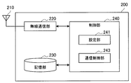
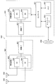
- FIG. 10 is a block diagram illustrating an example of the configuration of the terminal device 200 according to the present embodiment.
- the terminal device 200 includes an antenna unit 210, a wireless communication unit 220, a storage unit 230, and a control unit 240.
- Antenna unit 210 The antenna unit 210 radiates the signal output from the wireless communication unit 220 to the space as a radio wave. Further, the antenna unit 210 converts a radio wave in the space into a signal and outputs the signal to the wireless communication unit 220.
- the wireless communication unit 220 transmits and receives signals.
- the radio communication unit 220 receives a downlink signal from the base station and transmits an uplink signal to the base station.
- the wireless communication unit 220 can communicate with the base station 100 that forms a plurality of beams and communicates.
- Storage unit 230 The storage unit 230 temporarily or permanently stores a program for operating the terminal device 200 and various data.
- Control unit 240 provides various functions of the terminal device 200.
- the control unit 240 includes a setting unit 241 and a communication control unit 243.
- Control unit 240 may further include other components other than these components. That is, the control unit 240 can perform operations other than the operations of these components.
- the operations of the setting unit 241 and the communication control unit 243 will be described in detail later.
- the base station 100 is also referred to as an eNB 100
- the terminal device 200 is also referred to as a UE 200.
- the present embodiment is a form in which processing based on quality information is performed by notifying the UE 200 of beam quality information used for transmission of a beamformed downlink signal from the eNB 100.
- the technical problem of the present embodiment is that it is difficult to determine the handover timing under the above-described environment where beam tracking is performed.
- BQI Beam Quality Index
- BQI Beam Quality Index
- BQI may be used for handover decision, for example. For example, the UE 200 may not be handed over when the BQI is good, and may be handed over when the BQI is bad.
- the eNB 100 (for example, the setting unit 151) may set the BQI according to an arbitrary standard.
- the BQI may be set according to the degree to which the beam is directed to the cell edge. For example, a bad BQI may be set for a beam that is highly oriented toward the cell edge. Also, a good BQI may be set for a beam with a low degree toward the cell edge, that is, a beam with a high degree toward the cell center. Thereby, it is possible to prompt the UE 200 that receives the beam directed to the cell edge, that is, the UE 200 existing at the cell edge to perform handover or cell selection to an appropriate eNB 100.
- the BQI may be set according to the angle formed by the beam direction and the reference direction.
- the reference direction is a horizontal direction or a vertical direction.
- the BQI is set according to an angle formed by the beam direction and the horizontal direction (in other words, an angle in the vertical direction).
- the vertical angle of the beam typically corresponds to the degree to which it faces the cell edge.
- an angle in the horizontal direction is set to 0 degree
- an angle in the vertical direction that is, the direction of the ground
- an angle in the zenith direction that is the reverse direction of the vertical direction is set to 90 degrees.
- a bad BQI is set for a beam whose angle is 0 degrees or close to 0 degrees
- a good beam is set for a beam whose angle is close to -90 degrees or -90 degrees or a beam close to 90 degrees or 90 degrees. Also good.
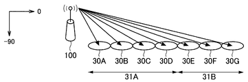
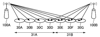
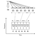
- FIGS. 11 and 12 are diagrams for explaining an example of the BQI according to the present embodiment.
- the eNB 100 can transmit a downlink signal using a plurality of beams.
- the eNB 100 may transmit a downlink signal beamformed using beams addressed to the areas 30A to 30G.
- the eNB 100 is located at a height of about 10 m (meters) from the ground, and the UE 200 is located at a height of about 1 to 2 m from the ground. Therefore, as the beam vertical angle is closer to -90 degrees, there is less influence in the horizontal direction (that is, the beam is difficult to reach far from the center of the cell), and thus it is less likely to interfere with the neighboring eNB and from the neighboring eNB. Less susceptible to interference. Therefore, the eNB 100 sets a good BQI for a beam transmitted to the range 31A close to the vertical direction, that is, a beam whose vertical angle is close to ⁇ 90 degrees.
- the eNB 100 ⁇ / b> B that is a neighboring eNB may be more suitable for providing a beam in the range 31 ⁇ / b> B than the eNB 100 ⁇ / b> A (corresponding to the eNB 100 in FIG. 11). Therefore, the eNB 100A sets a bad BQI for a beam transmitted to the range 31B close to the horizontal direction, that is, a beam whose vertical angle is close to 0 degrees.
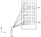
- FIG. 13 is a diagram for explaining an example of the BQI according to the present embodiment.
- the UE 200 may exist at a position higher than the eNB 100, such as the UE 200 in the building.
- eNB100 will transmit the downlink signal beam-formed to the zenith direction (90 degree) side rather than the horizontal direction (0 degree).
- a beam having a vertical angle close to 90 degrees is provided to the UE 200 existing on a higher floor.
- the eNB 100 sets a good BQI for a beam transmitted to the range 31C close to the zenith direction, that is, a beam whose vertical angle is close to 90 degrees.
- the eNB 100 sets a bad BQI for a beam transmitted to the range 31D close to the horizontal direction, that is, a beam whose vertical angle is close to 0 degrees.
- the BQI is set according to the angle between the beam direction and the horizontal direction (that is, the angle in the vertical direction).
- the BQI is set according to the angle between the beam direction and the vertical direction. In other words. In that case, the above -90 degrees may be read as 0 degrees, the 0 degrees as 90 degrees, and the 90 degrees as 180 degrees.
- the beam quality information can be expressed in various formats such as the BQI, information indicating the angle formed by the beam direction and the horizontal direction, or information indicating the degree to which the beam faces the cell edge. However, it is considered that the degree of freedom of expression is higher when the quality information is represented by BQI.
- the quality information is also simply referred to as BQI, but the quality information of the present technology is not limited to BQI.
- the beam quality information may be regarded as information associated with the beam direction.
- the beam quality information may be set based on the positional relationship with the neighboring eNB 100. For example, bad quality information may be set for a beam directed in the direction of the neighboring eNB 100, and good quality information may be set for a beam directed in another direction. Considering that the small cell ON / OFF can be switched, it is desirable that such dynamic setting is possible.
- the eNB 100 (for example, the communication control unit 153) notifies the UE 200 of quality information indicating the quality related to the beam direction. For example, when the eNB 100 transmits a downlink signal, the eNB 100 notifies the BQI in association with the downlink signal. As a result, the UE 200 can perform processing such as handover or cell selection based on the BQI. This point will be specifically described with reference to FIG.
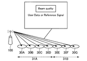
- FIG. 14 is a diagram for explaining a BQI notification method according to the present embodiment.
- the eNB 100 transmits a downlink signal that is beam-formed using a beam, including BQI.
- a control region for carrying beam quality information is prepared in the downlink signal, and the eNB 100 may notify the control region including the quality information.
- the eNB 100 transmits a good BQI in the control area of the downlink signal beamformed using the beam addressed to the range 31A.
- eNB100 is transmitted including the bad BQI in the control area
- This downlink signal may be a data signal including user data or a reference signal.
- the UE 200 receives the downlink signal transmitted from the eNB 100 using the beam, thereby obtaining the quality information indicating the quality related to the direction of the beam used for transmitting the downlink signal. get.
- the UE 200 acquires the BQI of the beam used for transmission of the data signal or reference signal from the control region of the data signal or reference signal transmitted from the eNB 100 using the beam.
- the reference signal including BQI it is difficult to transmit the reference signal including BQI.
- the reference signal that the eNB transmits for cell selection for example, different code sequences are used between eNBs so that the UE can identify the source eNB. Therefore, the UE can identify from which eNB the reference signal has arrived.
- the UE since the same reference signal is transmitted even when different beams are used from the same eNB, the UE uses each of the reference signals transmitted using different beams coming from the same eNB. It is difficult to identify each beam.
- sequences orthogonal to each other between eNBs are used as code sequences used as reference signals. Therefore, it is difficult to include information (for example, BQI) that cannot be acquired without decoding in such a reference signal.
- the eNB 100 (for example, the communication control unit 153) notifies the UE 200 of the quality information by transmitting the reference signal using the beam and using the resource associated with the quality information of the beam. That is, the eNB 100 implicitly notifies the UE 200 of the BQI by transmitting the beamformed reference signal using the resource corresponding to the BQI of the beam to be used. As a result, the eNB 100 can notify the UE 200 of the BQI without providing a control region in the reference signal and including the BQI.
- the beamformed downlink reference signal is also referred to as BF DL RS (Beam Formed Downlink Reference Signal).
- the eNB 100 notifies the UE 200 of setting information for causing the UE 200 to acquire quality information indicating the quality related to the beam direction.
- This setting information includes information indicating a resource corresponding to the quality information.
- the setting information includes information indicating a resource corresponding to a beam whose BQI is 0, and information indicating a resource corresponding to a beam whose BQI is 0. Thereby, it becomes possible to make UE200 acquire BQI notified implicitly.
- dedicated signaling Dedicated Signaling
- system information for example, SIB (System Information Block) or MIB (Master Information Block) etc.
- SIB System Information Block
- MIB Master Information Block
- the UE 200 (for example, the communication control unit 243) transmits the quality information corresponding to the resource used for receiving the reference signal to the reference signal based on the setting information in which the beam quality information is associated with the resource. Acquired as quality information of the used beam. For example, the UE 200 acquires the BQI corresponding to the resource for which the BF DL RS is received as the BQI of the beam used for transmission of the BF DL RS.
- the UE 200 (for example, the setting unit 241) performs resource setting based on the setting information. For example, the UE 200 performs a setting for associating a BQI with a resource based on the setting information. Thereby, the UE 200 can recognize that the BQI of the BF DL RS received in a certain resource is the BQI set in association with the resource.
- the resources used for transmission of the BF DL RS are orthogonal among resources associated with different quality information.
- a resource corresponding to a beam having a BQI of 0 and a resource corresponding to a beam having a BQI of 1 are orthogonal to each other in at least one of a time domain, a frequency domain, and a code domain.
- the UE 200 can identify to which BQI each received beam belongs.
- a plurality of beams for which the same BQI is set may be transmitted using one resource in common, or may be transmitted using different resources associated with the same BQI. .
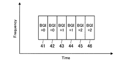
- FIG. 15 is a diagram illustrating an example of a correspondence relationship between BQIs and resources according to the present embodiment.
- This figure shows an example in which resources associated with different BQIs are orthogonal in the time domain.
- a BF DL RS beamformed by a beam having a BQI of 0 is transmitted / received by the resource 41 or 42.
- the BF DL RS that is beamformed by a beam having a BQI of 1 is transmitted / received by the resource 43 or 44.
- the BF DL RS that is beamformed by a beam having a BQI of 2 is transmitted / received by the resource 45 or 46.
- the resources 41 and 42, the resources 43 and 44, and the resources 45 and 46 are orthogonal to each other in the time domain.
- FIG. 16 is a diagram illustrating an example of a correspondence relationship between BQIs and resources according to the present embodiment.
- the correspondence between the resources shown in FIG. 15 and the BF DL RS transmitted from the eNB 100 is shown.
- a BF DL RS that is beamformed by a beam addressed to the area 30A is transmitted and received by the resource 41.
- the BF DL RS that is beamformed by the beam addressed to the area 30B is transmitted and received by the resource 42.
- the BF DL RS beamformed by the beam addressed to the area 30C is transmitted and received by the resource 43.
- the BF DL RS that is beamformed by the beam addressed to the area 30D is transmitted and received by the resource 44.
- the BF DL RS that is beamformed by the beam addressed to the area 30E is transmitted and received by the resource 45.
- the BF DL RS beamformed by the beam addressed to the area 30F is transmitted / received by the resource 46.
- the UE 200 measures which resource has a large received power while connected to the eNB 100. Then, if the received power in the resource 41 or 42 with a BQI of 0 is large, the UE 200 continues the connection as it is. On the other hand, if the received power in the resource 45 or 46 with BQI of 2 is large, the UE 200 may request the eNB 100 that is the serving eNB to perform handover to the neighboring eNB. In FIG. 16, one beam corresponds to one resource, but a plurality of beams for which the same BQI is set may correspond to one resource.
- FIG. 17 is a diagram illustrating an example of a correspondence relationship between BQIs and resources according to the present embodiment.
- This figure shows an example in which resources associated with different quality information are orthogonal in the frequency domain.
- a BF DL RS that is beamformed by a beam with a BQI of 0 is transmitted / received by the resource 51 or 52.
- the BF DL RS beamformed by a beam having a BQI of 1 is transmitted / received by the resource 53 or 54.
- the BF DL RS that is beamformed by a beam having a BQI of 2 is transmitted / received by the resource 55 or 56.
- the resources 51 and 52, the resources 53 and 54, and the resources 55 and 56 are orthogonal to each other in the frequency domain.
- the association between the BQI and the resource described above is notified from the eNB 100 to the UE 200 as setting information.
- the setting information includes, for example, information that the beam i uses the resource k whose BQI is j.
- the UE 200 can identify that the BQI of the beam i received at the resource k is j with reference to this setting information.
- the above-described association between the BQI and the resource may be applied not only to the BF DL RS but also to the data signal. That is, the eNB 100 may implicitly notify the UE 200 of the BQI by transmitting a data signal using a beam and using a resource associated with the BQI of the beam.
- the UE 200 may select the connection candidate eNB 100 based on the beam quality information. Selecting the connection candidate eNB 100 may mean, for example, handover in an RRC connected (Radio Resource Control Connected) state or cell selection in an RRC idle (Idle) state. For example, in an environment in which the eNB 100 follows a sharp beam with directivity according to the movement of the UE, the UE 200 performs a handover to a more appropriate eNB 100 when BQI is poor even though good downlink quality is provided. Alternatively, cell selection can be performed. Thereby, it becomes possible to suppress the interference to an adjacent cell and the interference from an adjacent cell.
- RRC connected Radio Resource Control Connected
- Idle RRC idle
- received power is an evaluation index for handover or cell selection.
- the beam quality information for example, BQI
- the relationship between received power and BQI can be set arbitrarily.
- the UE 200 may select a connection candidate eNB 100 based on the quality information for a plurality of eNBs 100 whose difference in information indicating the received power of the reference signal is less than a threshold.
- the UE 200 may prioritize the eNB 100 that is the source of the BF DL RS with better BQI for the plurality of eNBs 100 in which the received power of the BF DL RS is both within the predetermined range (that is, the connection candidate). As may be selected).
- An example of such an evaluation index is shown in Table 2 below.
- the UE 200 selects a better BF DL RS BQI from among the eNBs 100A and 100B as a connection candidate. For example, when the received power of the BF DL RS provided by the eNB 100A is -70 dBm and the received power of the BF DL RS provided by the eNB 100B is -90 dBm, the received power of both is not included in the same range. Then, UE200 selects the one where RSRP is higher among eNB100A and 100B as a connection candidate.
- Measurement report trigger When the UE 200 is in the RRC connection state and connected to the eNB 100, a measurement report is transmitted in order for the eNB 100 to make a handover decision.
- the measurement report trigger is a condition that triggers the transmission operation of the measurement report.
- a measurement report trigger may also be referred to as a measurement trigger or a measurement event.
- a measurement trigger considering BQI is provided.
- the serving eNB that is, the source eNB
- the target eNB is assumed to be eNB 100B.
- the UE 200 (for example, the communication control unit 243) transmits a measurement report based on a measurement report trigger related to beam quality information. For example, the UE 200 compares the BQI of the BF DL RS from the serving eNB 100A with the BQI of the BF DL RS from the target eNB 100B, and transmits a measurement report based on the comparison result. Thereby, the UE 200 can prompt a handover by transmitting a measurement report when there is a target eNB 100B having a poor BQI and a good BQI even if a good downlink quality is provided from the serving eNB 100A. Become.
- the type 1 measurement report trigger is that there is a connection candidate eNB 100B having better quality information than the serving eNB 100A being connected. For example, when the BQI of the BF DL RS from the target eNB 100B is better than the BQI of the BF DL RS from the serving eNB 100A, the UE 200 transmits a measurement report to the serving eNB 100A. More simply, the UE 200 transmits a measurement report when there is a target eNB 100B having a better BQI than the serving eNB 100A.
- the type 2 measurement report trigger is that there is a connection candidate eNB 100B whose quality information is better than the connected eNB 100A because the difference in information indicating the received power of the reference signal with the connected eNB 100A is less than the threshold.
- the UE 200 has a difference between the RSRP of the BF DL RS from the serving eNB 100A and the RSRP of the BF DL RS from the target eNB 100B less than the threshold X, and the UE 200 from the target eNB 100B is more than the BQI of the BF DL RS from the serving eNB 100A.
- the BQI of BF DL RS is better, a measurement report is transmitted to the serving eNB 100A. More simply, the UE 200 transmits a measurement report when there is no significant difference in RSRP and there is a target eNB 100B having a better BQI than the serving eNB 100A.
- the measurement report includes quality information of the connected eNB 100A and the connection candidate eNB 100B.
- the measurement report may include BQI in addition to RSRP that was included in LTE. More specifically, the measurement report may include the RSRP and BQI of the BF DL RS provided from the serving eNB 100A and the RSRP and BQI of the BF DL RS provided from the target eNB 100B.
- eNB100 (for example, communication control part 153) performs the handover determination regarding UE200 based on the measurement report containing the quality information of BF DL RS which UE200 received. For example, the same criteria as the measurement trigger shown in Table 3 above may be used to determine whether or not to allow handover.
- the BQI is included in the measurement report, so that the eNB 100 can perform the handover determination considering the BQI.
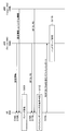
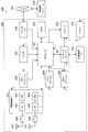
- FIG. 18 is a sequence diagram illustrating an example of the flow of the handover process of the UE 200 in the RRC connection state executed in the system 1 according to the present embodiment.
- the UE 200, the source eNB 100A, and the target eNB 100B are involved in this sequence. It is assumed that UE 200 is being connected to eNB 100A.
- the UE 200 receives setting information transmitted from the source eNB 100A using dedicated signaling or system information (step S102). Moreover, UE200 receives the setting information transmitted using the system information from target eNB100B (step S104).
- the setting information includes, for example, information indicating the correspondence between beam quality information and resources used for transmission of the BF DL RS beamformed by the beam.
- the UE 200 performs resource setting based on the received setting information (step S106). For example, the UE 200 performs a setting for associating a BQI with a resource based on the setting information.
- each of the source eNB 100A and the target eNB 100B transmits a BF DL RS to the UE 200 (steps S108 and S110). At that time, each of the source eNB 100A and the target eNB 100B transmits the BF DL RS using each resource corresponding to the BQI of the beam used for transmission of the BF DL RS.
- the UE 200 determines the condition of the measurement report trigger (step S112), and transmits the measurement report including RSRP and BQI to the serving eNB 100A when the condition is satisfied (step S114).
- a type 1 measurement report trigger is employed.
- the UE 200 transmits a measurement report when the BQI of the BF DL RS from the target eNB 100B is better than the BQI of the BF DL RS from the source eNB 100A.
- a type 2 measurement report trigger is employed.
- the UE 200 transmits a measurement report when there is no significant difference in RSRP between the BF DL RS from the source eNB 100A and the BF DL RS from the target eNB 100B, and the latter has a better BQI than the former.
- the eNB 100 performs handover determination based on the received measurement report (step S116).
- FIG. 19 is a sequence diagram illustrating an example of a cell selection process flow of the UE 200 in the RRC idle state that is executed in the system 1 according to the present embodiment. In this sequence, UE 200, eNB 100A, and eNB 100B are involved.
- the UE 200 receives setting information transmitted from the eNB 100A using system information (step S202). Moreover, UE200 receives the setting information transmitted using system information from eNB100B (step S204).
- the setting information includes, for example, information indicating the correspondence between beam quality information and resources used for transmission of the BF DL RS beamformed by the beam.
- the UE 200 performs resource setting based on the received setting information (step S206). For example, the UE 200 performs a setting for associating a BQI with a resource based on the setting information.
- each of the eNB 100A and the eNB 100B transmits a BF DL RS to the UE 200 (steps S208 and S210). At that time, each of the eNB 100A and the eNB 100B transmits the BF DL RS using each resource corresponding to the BQI of the beam used for transmission of the BF DL RS.
- the UE 200 performs cell selection (step S212). For example, the UE 200 selects a connection candidate eNB 100 according to the evaluation index shown in Table 2 above. For example, when both the BF DL RS from the eNB 100A and the RSRP of the BF DL RS from the eNB 100B are within a predetermined range, the UE 200 selects the eNB that is the transmission source of the BF DL RS with better BQI as a connection candidate. Moreover, UE200 selects eNB100 of the transmission source of BF DL RS with higher RSRP as a connection candidate in other cases.
- the UE 200 when the eNB 100A is selected as a connection candidate, the UE 200 performs a random access procedure with the eNB 100A (step S214). On the other hand, when eNB 100B is selected as a connection candidate, UE 200 performs a random access procedure with eNB 100B (step S216).
- Second Embodiment >> In the present embodiment, the BQI evaluation index is changed according to the scale of the eNB 100.
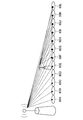
- FIG. 20 is a diagram for explaining a technical problem according to the present embodiment.
- the macro cell eNB has an antenna arranged at a position higher than that of the small cell eNB, and tends to transmit a signal with higher power than the small cell eNB.
- the macro cell eNB provides a beam to a wide range in the areas 60A to 60L.
- the small cell eNB provides a beam to a narrow range in the areas 60F to 60L.
- the transmission power difference of the reference signal between the macro cell eNB 100A and the small cell eNB 100B becomes small due to the effect of the beam. Therefore, when selecting a connection candidate, it is considered that the macro cell eNB 100A and the small cell eNB 100B are often compared based on the BQI. This point will be described in detail with reference to FIG.
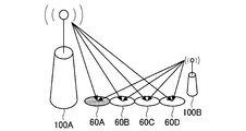
- FIG. 21 is a diagram for explaining a technical problem according to the present embodiment.
- each of the macro cell eNB 100A and the small cell eNB 100B provides a beam to the areas 60A to 60D.
- a connection candidate is selected based on the BQI. For example, regarding the BF DL RS transmitted using the beam addressed to the area 60A, it is considered that the BF DL RS from the macro cell eNB 100A has a better BQI than the BF DL RS from the small cell eNB 100B. This is because the area 60A is closer to the macro cell eNB 100A, and thus a beam close to the vertical direction is provided from the macro cell eNB 100A. Therefore, UE200 will select macrocell eNB100A as a connection candidate.
- the UE 200 can more easily select the small cell eNB 100B as a connection candidate than the macro cell eNB 100A. This is because, rather than transmitting downlink data from the macro cell eNB 100A, transmitting the downlink data distributed from a plurality of small cells eNB 100B provides a cell split gain, resulting in a higher overall system throughput. It is for improving. Therefore, in the example illustrated in FIG. 21, it is desirable to provide a mechanism by which the UE 200 located in the area 60A can select the small cell eNB 100B as a connection candidate.
- the UE 200 may select a connection candidate base station only between the eNBs 100 having the same cell size based on the beam quality information. For example, when the UE 200 selects a connection candidate from among the plurality of small cells eNB 100, as described with reference to Table 2 or Table 3 in the first embodiment, the connection candidate eNB 100 is based on the BQI. Select.
- the UE 200 selects a connection candidate base station by giving an advantage to the eNB 100 having a smaller cell size and comparing the received power among the eNBs 100 having the same cell size. For example, when selecting a connection candidate from the small cell eNB 100 and the macro cell eNB 100, the UE 200 employs the above-described evaluation index in LTE.
- This mechanism allows the UE 200 to select the small cell eNB 100 as a connection candidate even if the UE 200 is located near the macro cell eNB 100.
- the small cell and the macro cell were described here as an example of a cell, a femto cell, a moving cell, etc. can also be considered as an example of a cell.
- the fact that the cell sizes are equal may be regarded as having the same priority as a connection candidate.
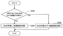
- FIG. 22 is a flowchart showing an example of a connection candidate selection process performed in the UE 200 according to the present embodiment.
- the UE 200 determines whether the two eNBs 100 to be compared have the same cell size (step S302). For example, first, the UE 200 identifies whether the eNB 100 that is the transmission source of the BF DL RS is a macro cell eNB or a small cell eNB based on the received BF DL RS code sequence or based on the received system information. To do. And UE200 compares the magnitude
- the UE 200 selects a connection candidate eNB 100 in consideration of the BQI. For example, the UE 200 performs cell selection using the evaluation index shown in Table 2, or transmits a measurement report based on the measurement report trigger shown in Table 3.
- the UE 200 selects the eNB 100 as a connection candidate without considering the BQI.
- the UE 200 employs the LTE evaluation index, and selects the eNB 100 as a connection candidate based on the comparison result of the received power when the eNB 100 having a smaller cell size has an advantage.
- the base station 100 may be realized as any type of eNB (evolved Node B) such as a macro eNB or a small eNB.
- the small eNB may be an eNB that covers a cell smaller than a macro cell, such as a pico eNB, a micro eNB, or a home (femto) eNB.
- the base station 100 may be realized as another type of base station such as a NodeB or a BTS (Base Transceiver Station).
- Base station 100 may include a main body (also referred to as a base station apparatus) that controls radio communication, and one or more RRHs (Remote Radio Heads) that are arranged at locations different from the main body. Further, various types of terminals described later may operate as the base station 100 by temporarily or semi-permanently executing the base station function.
- a main body also referred to as a base station apparatus
- RRHs Remote Radio Heads
- the terminal device 200 is a smartphone, a tablet PC (Personal Computer), a notebook PC, a portable game terminal, a mobile terminal such as a portable / dongle type mobile router or a digital camera, or an in-vehicle terminal such as a car navigation device. It may be realized as.
- the terminal device 200 may be realized as a terminal (also referred to as an MTC (Machine Type Communication) terminal) that performs M2M (Machine To Machine) communication.
- the terminal device 200 may be a wireless communication module (for example, an integrated circuit module configured by one die) mounted on these terminals.
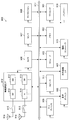
- FIG. 23 is a block diagram illustrating a first example of a schematic configuration of an eNB to which the technology according to the present disclosure may be applied.
- the eNB 800 includes one or more antennas 810 and a base station device 820. Each antenna 810 and the base station apparatus 820 can be connected to each other via an RF cable.
- Each of the antennas 810 has a single or a plurality of antenna elements (for example, a plurality of antenna elements constituting a MIMO antenna), and is used for transmission and reception of radio signals by the base station apparatus 820.
- the eNB 800 includes a plurality of antennas 810 as illustrated in FIG. 23, and the plurality of antennas 810 may respectively correspond to a plurality of frequency bands used by the eNB 800, for example. 23 shows an example in which the eNB 800 includes a plurality of antennas 810, the eNB 800 may include a single antenna 810.
- the base station apparatus 820 includes a controller 821, a memory 822, a network interface 823, and a wireless communication interface 825.
- the controller 821 may be a CPU or a DSP, for example, and operates various functions of the upper layer of the base station apparatus 820. For example, the controller 821 generates a data packet from the data in the signal processed by the wireless communication interface 825, and transfers the generated packet via the network interface 823. The controller 821 may generate a bundled packet by bundling data from a plurality of baseband processors, and may transfer the generated bundled packet. In addition, the controller 821 is a logic that executes control such as radio resource control, radio bearer control, mobility management, inflow control, or scheduling. May have a typical function. Moreover, the said control may be performed in cooperation with a surrounding eNB or a core network node.
- the memory 822 includes RAM and ROM, and stores programs executed by the controller 821 and various control data (for example, terminal list, transmission power data, scheduling data, and the like).
- the network interface 823 is a communication interface for connecting the base station device 820 to the core network 824.
- the controller 821 may communicate with the core network node or other eNB via the network interface 823.
- the eNB 800 and the core network node or another eNB may be connected to each other by a logical interface (for example, an S1 interface or an X2 interface).
- the network interface 823 may be a wired communication interface or a wireless communication interface for wireless backhaul.
- the network interface 823 may use a frequency band higher than the frequency band used by the wireless communication interface 825 for wireless communication.
- the wireless communication interface 825 supports any cellular communication scheme such as LTE (Long Term Evolution) or LTE-Advanced, and provides a wireless connection to terminals located in the cell of the eNB 800 via the antenna 810.
- the wireless communication interface 825 may typically include a baseband (BB) processor 826, an RF circuit 827, and the like.
- the BB processor 826 may perform, for example, encoding / decoding, modulation / demodulation, and multiplexing / demultiplexing, and each layer (for example, L1, MAC (Medium Access Control), RLC (Radio Link Control), and PDCP).
- Various signal processing of Packet Data Convergence Protocol
- Packet Data Convergence Protocol is executed.
- the BB processor 826 may have some or all of the logical functions described above instead of the controller 821.
- the BB processor 826 may be a module that includes a memory that stores a communication control program, a processor that executes the program, and related circuits. The function of the BB processor 826 may be changed by updating the program. Good.
- the module may be a card or a blade inserted into a slot of the base station apparatus 820, or a chip mounted on the card or the blade.
- the RF circuit 827 may include a mixer, a filter, an amplifier, and the like, and transmits and receives a radio signal via the antenna 810.
- the wireless communication interface 825 includes a plurality of BB processors 826 as illustrated in FIG. 23, and the plurality of BB processors 826 may respectively correspond to a plurality of frequency bands used by the eNB 800, for example. Further, the wireless communication interface 825 includes a plurality of RF circuits 827 as shown in FIG. 23, and the plurality of RF circuits 827 may respectively correspond to a plurality of antenna elements, for example. 23 shows an example in which the wireless communication interface 825 includes a plurality of BB processors 826 and a plurality of RF circuits 827, the wireless communication interface 825 includes a single BB processor 826 or a single RF circuit 827. But you can.
- the eNB 800 illustrated in FIG. 23 one or more components (setting unit 151 and / or communication control unit 153) included in the control unit 150 described with reference to FIG. 9 are implemented in the wireless communication interface 825. Also good. Alternatively, at least some of these components may be implemented in the controller 821. As an example, the eNB 800 includes a module including a part (for example, the BB processor 826) or all of the wireless communication interface 825 and / or the controller 821, and the one or more components are mounted in the module. Good. In this case, the module stores a program for causing the processor to function as the one or more components (in other words, a program for causing the processor to execute the operation of the one or more components). The program may be executed.
- the module stores a program for causing the processor to function as the one or more components (in other words, a program for causing the processor to execute the operation of the one or more components). The program may be executed.
- a program for causing a processor to function as the one or more components is installed in the eNB 800, and the radio communication interface 825 (eg, the BB processor 826) and / or the controller 821 executes the program.
- the eNB 800, the base station apparatus 820, or the module may be provided as an apparatus including the one or more components, and a program for causing a processor to function as the one or more components is provided. May be.
- a readable recording medium in which the program is recorded may be provided.
- the radio communication unit 120 described with reference to FIG. 9 may be implemented in the radio communication interface 825 (for example, the RF circuit 827) in the eNB 800 illustrated in FIG. Further, the antenna unit 110 may be mounted on the antenna 810.
- the network communication unit 130 may be implemented in the controller 821 and / or the network interface 823.
- the storage unit 140 may be implemented in the memory 822.
- FIG. 24 is a block diagram illustrating a second example of a schematic configuration of an eNB to which the technology according to the present disclosure may be applied.
- the eNB 830 includes one or more antennas 840, a base station apparatus 850, and an RRH 860. Each antenna 840 and RRH 860 may be connected to each other via an RF cable. Base station apparatus 850 and RRH 860 can be connected to each other via a high-speed line such as an optical fiber cable.
- Each of the antennas 840 has a single or a plurality of antenna elements (for example, a plurality of antenna elements constituting a MIMO antenna), and is used for transmission / reception of radio signals by the RRH 860.
- the eNB 830 includes a plurality of antennas 840 as illustrated in FIG. 24, and the plurality of antennas 840 may respectively correspond to a plurality of frequency bands used by the eNB 830, for example. 24 shows an example in which the eNB 830 has a plurality of antennas 840, but the eNB 830 may have a single antenna 840.
- the base station device 850 includes a controller 851, a memory 852, a network interface 853, a wireless communication interface 855, and a connection interface 857.
- the controller 851, the memory 852, and the network interface 853 are the same as the controller 821, the memory 822, and the network interface 823 described with reference to FIG.
- the wireless communication interface 855 supports a cellular communication method such as LTE or LTE-Advanced, and provides a wireless connection to a terminal located in a sector corresponding to the RRH 860 via the RRH 860 and the antenna 840.
- the wireless communication interface 855 may typically include a BB processor 856 and the like.
- the BB processor 856 is the same as the BB processor 826 described with reference to FIG. 23 except that the BB processor 856 is connected to the RF circuit 864 of the RRH 860 via the connection interface 857.
- the wireless communication interface 855 includes a plurality of BB processors 856 as illustrated in FIG.
- the plurality of BB processors 856 may respectively correspond to a plurality of frequency bands used by the eNB 830, for example.
- 24 shows an example in which the wireless communication interface 855 includes a plurality of BB processors 856, the wireless communication interface 855 may include a single BB processor 856.
- connection interface 857 is an interface for connecting the base station device 850 (wireless communication interface 855) to the RRH 860.
- the connection interface 857 may be a communication module for communication on the high-speed line that connects the base station apparatus 850 (wireless communication interface 855) and the RRH 860.
- the RRH 860 includes a connection interface 861 and a wireless communication interface 863.
- connection interface 861 is an interface for connecting the RRH 860 (wireless communication interface 863) to the base station device 850.
- the connection interface 861 may be a communication module for communication on the high-speed line.
- the wireless communication interface 863 transmits and receives wireless signals via the antenna 840.
- the wireless communication interface 863 may typically include an RF circuit 864 and the like.
- the RF circuit 864 may include a mixer, a filter, an amplifier, and the like, and transmits and receives wireless signals via the antenna 840.
- the wireless communication interface 863 includes a plurality of RF circuits 864 as illustrated in FIG. 24, and the plurality of RF circuits 864 may correspond to, for example, a plurality of antenna elements, respectively. 24 shows an example in which the wireless communication interface 863 includes a plurality of RF circuits 864, the wireless communication interface 863 may include a single RF circuit 864.
- one or more components (setting unit 151 and / or communication control unit 153) included in the control unit described with reference to FIG. 9 include the wireless communication interface 855 and / or the wireless communication. It may be implemented in interface 863. Alternatively, at least some of these components may be implemented in the controller 851.
- the eNB 830 includes a module including a part (for example, the BB processor 856) or the whole of the wireless communication interface 855 and / or the controller 851, and the one or more components are mounted in the module. Good.
- the module stores a program for causing the processor to function as the one or more components (in other words, a program for causing the processor to execute the operation of the one or more components).
- the program may be executed.
- a program for causing a processor to function as the one or more components is installed in the eNB 830, and the wireless communication interface 855 (eg, the BB processor 856) and / or the controller 851 executes the program.
- the eNB 830, the base station apparatus 850, or the module may be provided as an apparatus including the one or more components, and a program for causing a processor to function as the one or more components is provided. May be.
- a readable recording medium in which the program is recorded may be provided.
- the wireless communication unit 120 described with reference to FIG. 9 may be implemented in the wireless communication interface 863 (for example, the RF circuit 864).
- the antenna unit 110 may be mounted on the antenna 840.
- the network communication unit 130 may be implemented in the controller 851 and / or the network interface 853.
- the storage unit 140 may be mounted in the memory 852.
- FIG. 25 is a block diagram illustrating an example of a schematic configuration of a smartphone 900 to which the technology according to the present disclosure can be applied.
- the smartphone 900 includes a processor 901, a memory 902, a storage 903, an external connection interface 904, a camera 906, a sensor 907, a microphone 908, an input device 909, a display device 910, a speaker 911, a wireless communication interface 912, one or more antenna switches 915.
- One or more antennas 916, a bus 917, a battery 918 and an auxiliary controller 919 are provided.
- the processor 901 may be, for example, a CPU or a SoC (System on Chip), and controls the functions of the application layer and other layers of the smartphone 900.
- the memory 902 includes a RAM and a ROM, and stores programs executed by the processor 901 and data.
- the storage 903 can include a storage medium such as a semiconductor memory or a hard disk.
- the external connection interface 904 is an interface for connecting an external device such as a memory card or a USB (Universal Serial Bus) device to the smartphone 900.
- the camera 906 includes, for example, an image sensor such as a CCD (Charge Coupled Device) or a CMOS (Complementary Metal Oxide Semiconductor), and generates a captured image.
- the sensor 907 may include a sensor group such as a positioning sensor, a gyro sensor, a geomagnetic sensor, and an acceleration sensor.
- the microphone 908 converts sound input to the smartphone 900 into an audio signal.
- the input device 909 includes, for example, a touch sensor that detects a touch on the screen of the display device 910, a keypad, a keyboard, a button, or a switch, and receives an operation or information input from a user.
- the display device 910 has a screen such as a liquid crystal display (LCD) or an organic light emitting diode (OLED) display, and displays an output image of the smartphone 900.
- the speaker 911 converts an audio signal output from the smartphone 900 into audio.
- the wireless communication interface 912 supports any cellular communication method such as LTE or LTE-Advanced, and performs wireless communication.
- the wireless communication interface 912 may typically include a BB processor 913, an RF circuit 914, and the like.
- the BB processor 913 may perform, for example, encoding / decoding, modulation / demodulation, and multiplexing / demultiplexing, and performs various signal processing for wireless communication.
- the RF circuit 914 may include a mixer, a filter, an amplifier, and the like, and transmits and receives radio signals via the antenna 916.
- the wireless communication interface 912 may be a one-chip module in which the BB processor 913 and the RF circuit 914 are integrated.
- the wireless communication interface 912 may include a plurality of BB processors 913 and a plurality of RF circuits 914 as illustrated in FIG.
- FIG. 25 illustrates an example in which the wireless communication interface 912 includes a plurality of BB processors 913 and a plurality of RF circuits 914.
- the wireless communication interface 912 includes a single BB processor 913 or a single RF circuit 914. But you can.
- the wireless communication interface 912 may support other types of wireless communication methods such as a short-range wireless communication method, a proximity wireless communication method, or a wireless LAN (Local Area Network) method in addition to the cellular communication method.
- a BB processor 913 and an RF circuit 914 for each wireless communication method may be included.
- Each of the antenna switches 915 switches the connection destination of the antenna 916 among a plurality of circuits (for example, circuits for different wireless communication systems) included in the wireless communication interface 912.
- Each of the antennas 916 includes a single or a plurality of antenna elements (for example, a plurality of antenna elements constituting a MIMO antenna), and is used for transmission / reception of a radio signal by the radio communication interface 912.
- the smartphone 900 may include a plurality of antennas 916 as illustrated in FIG. Note that although FIG. 25 illustrates an example in which the smartphone 900 includes a plurality of antennas 916, the smartphone 900 may include a single antenna 916.
- the smartphone 900 may include an antenna 916 for each wireless communication method.
- the antenna switch 915 may be omitted from the configuration of the smartphone 900.
- the bus 917 connects the processor 901, the memory 902, the storage 903, the external connection interface 904, the camera 906, the sensor 907, the microphone 908, the input device 909, the display device 910, the speaker 911, the wireless communication interface 912, and the auxiliary controller 919 to each other.
- the battery 918 supplies power to each block of the smartphone 900 illustrated in FIG. 25 via a power supply line partially illustrated by a broken line in the drawing.
- the auxiliary controller 919 operates the minimum necessary functions of the smartphone 900 in the sleep mode.
- one or more components included in the control unit 240 described with reference to FIG. 10 are implemented in the wireless communication interface 912. May be. Alternatively, at least some of these components may be implemented in the processor 901 or the auxiliary controller 919.
- the smartphone 900 includes a module including a part (for example, the BB processor 913) or the whole of the wireless communication interface 912, the processor 901, and / or the auxiliary controller 919, and the one or more components in the module. May be implemented.
- the module stores a program for causing the processor to function as the one or more components (in other words, a program for causing the processor to execute the operation of the one or more components).
- the program may be executed.
- a program for causing a processor to function as the one or more components is installed in the smartphone 900, and the wireless communication interface 912 (eg, the BB processor 913), the processor 901, and / or the auxiliary controller 919 is The program may be executed.
- the smartphone 900 or the module may be provided as a device including the one or more components, and a program for causing a processor to function as the one or more components may be provided.
- a readable recording medium in which the program is recorded may be provided.
- the wireless communication unit 220 described with reference to FIG. 10 may be implemented in the wireless communication interface 912 (for example, the RF circuit 914).
- the antenna unit 210 may be mounted on the antenna 916.
- the storage unit 230 may be mounted in the memory 902.
- FIG. 26 is a block diagram illustrating an example of a schematic configuration of a car navigation device 920 to which the technology according to the present disclosure can be applied.
- the car navigation device 920 includes a processor 921, a memory 922, a GPS (Global Positioning System) module 924, a sensor 925, a data interface 926, a content player 927, a storage medium interface 928, an input device 929, a display device 930, a speaker 931, and wireless communication.
- the interface 933 includes one or more antenna switches 936, one or more antennas 937, and a battery 938.
- the processor 921 may be a CPU or SoC, for example, and controls the navigation function and other functions of the car navigation device 920.
- the memory 922 includes RAM and ROM, and stores programs and data executed by the processor 921.
- the GPS module 924 measures the position (for example, latitude, longitude, and altitude) of the car navigation device 920 using GPS signals received from GPS satellites.
- the sensor 925 may include a sensor group such as a gyro sensor, a geomagnetic sensor, and an atmospheric pressure sensor.
- the data interface 926 is connected to the in-vehicle network 941 through a terminal (not shown), for example, and acquires data generated on the vehicle side such as vehicle speed data.
- the content player 927 reproduces content stored in a storage medium (for example, CD or DVD) inserted into the storage medium interface 928.
- the input device 929 includes, for example, a touch sensor, a button, or a switch that detects a touch on the screen of the display device 930, and receives an operation or information input from the user.
- the display device 930 has a screen such as an LCD or an OLED display, and displays a navigation function or an image of content to be reproduced.
- the speaker 931 outputs the navigation function or the audio of the content to be played back.
- the wireless communication interface 933 supports any cellular communication method such as LTE or LTE-Advanced, and performs wireless communication.
- the wireless communication interface 933 may typically include a BB processor 934, an RF circuit 935, and the like.
- the BB processor 934 may perform, for example, encoding / decoding, modulation / demodulation, and multiplexing / demultiplexing, and performs various signal processing for wireless communication.
- the RF circuit 935 may include a mixer, a filter, an amplifier, and the like, and transmits and receives a radio signal via the antenna 937.
- the wireless communication interface 933 may be a one-chip module in which the BB processor 934 and the RF circuit 935 are integrated.
- the wireless communication interface 933 may include a plurality of BB processors 934 and a plurality of RF circuits 935 as shown in FIG. 26 shows an example in which the wireless communication interface 933 includes a plurality of BB processors 934 and a plurality of RF circuits 935, the wireless communication interface 933 includes a single BB processor 934 or a single RF circuit 935. But you can.
- the wireless communication interface 933 may support other types of wireless communication methods such as a short-range wireless communication method, a proximity wireless communication method, or a wireless LAN method in addition to the cellular communication method.
- a BB processor 934 and an RF circuit 935 may be included for each communication method.
- Each of the antenna switches 936 switches the connection destination of the antenna 937 among a plurality of circuits included in the wireless communication interface 933 (for example, circuits for different wireless communication systems).
- Each of the antennas 937 has a single or a plurality of antenna elements (for example, a plurality of antenna elements constituting a MIMO antenna), and is used for transmission / reception of a radio signal by the radio communication interface 933.
- the car navigation device 920 may include a plurality of antennas 937 as shown in FIG. FIG. 26 shows an example in which the car navigation apparatus 920 includes a plurality of antennas 937. However, the car navigation apparatus 920 may include a single antenna 937.
- the car navigation device 920 may include an antenna 937 for each wireless communication method.
- the antenna switch 936 may be omitted from the configuration of the car navigation device 920.
- the battery 938 supplies power to each block of the car navigation device 920 shown in FIG. 26 through a power supply line partially shown by broken lines in the drawing. Further, the battery 938 stores electric power supplied from the vehicle side.
- the car navigation apparatus 920 includes a module including a part (for example, the BB processor 934) or the whole of the wireless communication interface 933 and / or the processor 921, and the one or more components are mounted in the module. May be.
- the module stores a program for causing the processor to function as the one or more components (in other words, a program for causing the processor to execute the operation of the one or more components). The program may be executed.
- a program for causing a processor to function as the one or more components is installed in the car navigation device 920, and the wireless communication interface 933 (eg, the BB processor 934) and / or the processor 921 executes the program.
- the car navigation apparatus 920 or the module may be provided as an apparatus including the one or more components, and a program for causing a processor to function as the one or more components may be provided. Good.
- a readable recording medium in which the program is recorded may be provided.
- the wireless communication unit 220 described with reference to FIG. 10 may be implemented in the wireless communication interface 933 (for example, the RF circuit 935).
- the antenna unit 210 may be mounted on the antenna 937.
- the storage unit 230 may be implemented in the memory 922.
- the technology according to the present disclosure may be realized as an in-vehicle system (or vehicle) 940 including one or more blocks of the car navigation device 920 described above, an in-vehicle network 941, and a vehicle side module 942.
- vehicle-side module 942 generates vehicle-side data such as vehicle speed, engine speed, or failure information, and outputs the generated data to the in-vehicle network 941.
- the UE 200 receives the downlink signal transmitted using the beam from the eNB 100 that forms and communicates the beam, thereby transmitting the beam used for the transmission of the downlink signal.
- Obtain quality information indicating the quality of the direction For example, the UE 200 acquires quality information from the control region of the downlink signal, or acquires quality information corresponding to the resource used for receiving the downlink signal as the quality information of the beam used for transmitting the downlink signal. To do.
- the UE 200 can evaluate the quality of the beam used for transmission of the downlink signal received from the eNB 100.
- the UE 200 moves to a more appropriate eNB 100 when BQI is poor even though good downlink quality is provided. Handover or cell selection can be performed. Thereby, it becomes possible to suppress the interference to an adjacent cell and the interference from an adjacent cell.
- a communication unit communicating with a base station that forms and communicates with a beam;
- a control unit for obtaining quality information indicating quality related to a beam direction used for transmitting the downlink signal by receiving a downlink signal transmitted from the base station using a beam;
- a terminal device comprising: (2) The terminal apparatus according to (1), wherein the downlink signal is a reference signal.
- the control unit based on setting information in which the quality information of the beam and the resource are associated with each other, the quality information corresponding to the resource used for receiving the reference signal, the beam used for transmitting the reference signal The terminal device according to (2), acquired as the quality information.
- the terminal device (4) The terminal device according to (2) or (3), wherein the control unit selects a connection candidate base station based on the quality information.
- the control unit selects a connection candidate base station based on the quality information for a plurality of base stations whose difference in information indicating received power of the reference signal is less than a threshold value. Terminal equipment.
- the control unit transmits a measurement report based on a measurement report trigger related to the quality information, The terminal device according to (4), wherein the measurement report trigger is that there is a connection candidate base station having better quality information than a connected base station.
- the control unit transmits a measurement report based on a measurement report trigger related to the quality information, In the measurement report trigger, the difference in information indicating the reception power of the reference signal with the connected base station is less than a threshold value, and there is a connection candidate base station with better quality information than the connected base station.
- a communication unit that forms a beam and communicates with a terminal device; Setting information for causing the terminal device to acquire quality information indicating quality related to the direction of the beam, and a control unit for notifying the terminal device of the quality information;
- a base station comprising: (11) The said control part notifies the said quality information to the said terminal device by transmitting a reference signal using the resource matched with the said quality information of the said beam using the beam, The said (10).
- Base station (12) The base station according to (11), wherein the setting information includes information indicating a resource corresponding to the quality information.
- the resource used for transmission of the reference signal is the base station according to (11) or (12), wherein resources associated with different quality information are orthogonal to each other.
- the control unit according to any one of (11) to (13), wherein the control unit performs handover determination regarding the terminal device based on a measurement report including the quality information of the reference signal received by the terminal device.
- Base station The base station according to any one of (10) to (14), wherein the quality information is set according to an angle formed by a beam direction and a reference direction.
- the quality information is set according to a degree that a beam is directed to a cell edge.
- Computer A communication unit communicating with a base station that forms and communicates with a beam; A control unit for obtaining quality information indicating quality related to a beam direction used for transmitting the downlink signal by receiving a downlink signal transmitted from the base station using a beam; A recording medium on which a program for functioning as a recording medium is recorded.
- Computer A communication unit that forms a beam and communicates with a terminal device; Setting information for causing the terminal device to acquire quality information indicating quality related to the direction of the beam, and a control unit for notifying the terminal device of the quality information; A recording medium on which a program for functioning as a recording medium is recorded.
Landscapes
- Engineering & Computer Science (AREA)
- Computer Networks & Wireless Communication (AREA)
- Signal Processing (AREA)
- Physics & Mathematics (AREA)
- Computer Security & Cryptography (AREA)
- Electromagnetism (AREA)
- Quality & Reliability (AREA)
- Mathematical Physics (AREA)
- Mobile Radio Communication Systems (AREA)
- Radio Transmission System (AREA)
- Management Or Editing Of Information On Record Carriers (AREA)
- Two-Way Televisions, Distribution Of Moving Picture Or The Like (AREA)
- Optical Communication System (AREA)
Priority Applications (5)
| Application Number | Priority Date | Filing Date | Title |
|---|---|---|---|
| CN201780045304.1A CN109479202B (zh) | 2016-07-29 | 2017-06-16 | 终端装置、基站、方法和记录介质 |
| ES17833910T ES2949361T3 (es) | 2016-07-29 | 2017-06-16 | Dispositivo terminal, estación base, método y medio de grabación |
| US16/313,263 US10897296B2 (en) | 2016-07-29 | 2017-06-16 | Terminal apparatus, base station, method and recording medium |
| EP17833910.7A EP3493577B1 (en) | 2016-07-29 | 2017-06-16 | Terminal device, base station, method, and recording medium |
| KR1020197001452A KR102332909B1 (ko) | 2016-07-29 | 2017-06-16 | 단말 장치, 기지국, 방법 및 기록 매체 |
Applications Claiming Priority (2)
| Application Number | Priority Date | Filing Date | Title |
|---|---|---|---|
| JP2016150170A JP6769160B2 (ja) | 2016-07-29 | 2016-07-29 | 端末装置、基地局、方法及び記録媒体 |
| JP2016-150170 | 2016-07-29 |
Publications (1)
| Publication Number | Publication Date |
|---|---|
| WO2018020900A1 true WO2018020900A1 (ja) | 2018-02-01 |
Family
ID=61015755
Family Applications (1)
| Application Number | Title | Priority Date | Filing Date |
|---|---|---|---|
| PCT/JP2017/022400 Ceased WO2018020900A1 (ja) | 2016-07-29 | 2017-06-16 | 端末装置、基地局、方法及び記録媒体 |
Country Status (7)
| Country | Link |
|---|---|
| US (1) | US10897296B2 (enExample) |
| EP (1) | EP3493577B1 (enExample) |
| JP (1) | JP6769160B2 (enExample) |
| KR (1) | KR102332909B1 (enExample) |
| CN (1) | CN109479202B (enExample) |
| ES (1) | ES2949361T3 (enExample) |
| WO (1) | WO2018020900A1 (enExample) |
Cited By (1)
| Publication number | Priority date | Publication date | Assignee | Title |
|---|---|---|---|---|
| US11552686B2 (en) | 2018-05-25 | 2023-01-10 | Vivo Mobile Communication Co., Ltd. | Beam reporting based on detection of a trigger event |
Families Citing this family (9)
| Publication number | Priority date | Publication date | Assignee | Title |
|---|---|---|---|---|
| EP3459281B1 (en) * | 2016-05-20 | 2021-07-21 | Sony Corporation | Telecommunications apparatus and methods |
| CN107635241B (zh) * | 2017-09-27 | 2021-05-07 | 中兴通讯股份有限公司 | 下行数据的发送方法及装置、接收方法及装置、存储介质 |
| WO2020126039A1 (en) | 2018-12-21 | 2020-06-25 | Telefonaktiebolaget Lm Ericsson (Publ) | Methods, apparatus and machine-readable mediums related to wireless access in communication networks |
| WO2021147682A1 (en) * | 2020-01-25 | 2021-07-29 | Qualcomm Incorporated | Sounding reference signal configuration |
| CN111885549B (zh) * | 2020-06-29 | 2025-02-18 | 中兴通讯股份有限公司 | 信息采集方法、装置、存储介质及电子装置 |
| WO2022205438A1 (en) * | 2021-04-02 | 2022-10-06 | Zte Corporation | Systems and methods for reporting and beam management using artificial intelligence |
| US12108468B1 (en) * | 2021-04-09 | 2024-10-01 | T-Mobile Innovations Llc | Cell selection management for airborne mobile stations |
| WO2022236645A1 (en) * | 2021-05-10 | 2022-11-17 | Apple Inc. | Fast measurement with multiple concurrent beams |
| JP7734100B2 (ja) * | 2022-02-22 | 2025-09-04 | 株式会社国際電気 | メッシュネットワークシステム及び移動ノード |
Citations (3)
| Publication number | Priority date | Publication date | Assignee | Title |
|---|---|---|---|---|
| JP2006211366A (ja) * | 2005-01-28 | 2006-08-10 | Ntt Docomo Inc | 送信装置、送信方法、受信装置及び受信方法 |
| JP2015164281A (ja) | 2014-01-31 | 2015-09-10 | 株式会社Nttドコモ | ユーザ装置、基地局、及び通信方法 |
| WO2016013351A1 (ja) * | 2014-07-25 | 2016-01-28 | 株式会社Nttドコモ | 基地局、ユーザ装置および無線通信ネットワーク |
Family Cites Families (12)
| Publication number | Priority date | Publication date | Assignee | Title |
|---|---|---|---|---|
| EP2552154B1 (en) * | 2011-07-25 | 2014-12-31 | Alcatel Lucent | A femto-gateway, a cellular telecommunications network, and a method of identifying a handover target femtocell base station |
| US9520973B2 (en) * | 2012-07-12 | 2016-12-13 | Lg Electronics Inc. | Method for transmitting reference signal to antenna port in wireless access system |
| KR101957783B1 (ko) * | 2012-09-12 | 2019-03-13 | 삼성전자주식회사 | 무선 통신 시스템에서 핸드오버를 위한 장치 및 방법 |
| US9516563B2 (en) * | 2013-01-21 | 2016-12-06 | Intel Corporation | Apparatus, system and method of handover of a beamformed link |
| CN111163494B (zh) * | 2013-12-30 | 2025-06-17 | 华为技术有限公司 | 一种信道测量方法、小区切换方法、相关装置及系统 |
| EP2928234B1 (en) * | 2014-03-31 | 2016-05-25 | Alcatel Lucent | Methods For Operating A Mobile Station And A Base Station In A Radio Communication System, Mobile Station And Base Station Thereof |
| KR102171561B1 (ko) * | 2014-04-07 | 2020-10-29 | 삼성전자주식회사 | 빔포밍 기반 셀룰러 시스템의 상향링크 빔 추적 방법 및 장치 |
| CN106416346B (zh) * | 2014-05-29 | 2020-06-16 | 索尼公司 | 设备和方法 |
| EP3165022B1 (en) * | 2014-07-02 | 2020-06-03 | Telefonaktiebolaget LM Ericsson (publ) | Network node and method of taking a mobility decision by considering the beamforming capabilities of the neighbouring nodes |
| JP6406777B2 (ja) * | 2014-09-23 | 2018-10-17 | ホアウェイ・テクノロジーズ・カンパニー・リミテッド | ビーム構成方法、基地局、およびユーザ機器 |
| EP3354067B1 (en) * | 2015-09-21 | 2020-11-18 | Telefonaktiebolaget LM Ericsson (publ) | A source and a target network node and respective methods performed thereby for performing handover of a wireless device |
| US11088747B2 (en) * | 2016-04-13 | 2021-08-10 | Qualcomm Incorporated | System and method for beam management |
-
2016
- 2016-07-29 JP JP2016150170A patent/JP6769160B2/ja active Active
-
2017
- 2017-06-16 EP EP17833910.7A patent/EP3493577B1/en active Active
- 2017-06-16 ES ES17833910T patent/ES2949361T3/es active Active
- 2017-06-16 WO PCT/JP2017/022400 patent/WO2018020900A1/ja not_active Ceased
- 2017-06-16 KR KR1020197001452A patent/KR102332909B1/ko active Active
- 2017-06-16 US US16/313,263 patent/US10897296B2/en active Active
- 2017-06-16 CN CN201780045304.1A patent/CN109479202B/zh active Active
Patent Citations (3)
| Publication number | Priority date | Publication date | Assignee | Title |
|---|---|---|---|---|
| JP2006211366A (ja) * | 2005-01-28 | 2006-08-10 | Ntt Docomo Inc | 送信装置、送信方法、受信装置及び受信方法 |
| JP2015164281A (ja) | 2014-01-31 | 2015-09-10 | 株式会社Nttドコモ | ユーザ装置、基地局、及び通信方法 |
| WO2016013351A1 (ja) * | 2014-07-25 | 2016-01-28 | 株式会社Nttドコモ | 基地局、ユーザ装置および無線通信ネットワーク |
Cited By (1)
| Publication number | Priority date | Publication date | Assignee | Title |
|---|---|---|---|---|
| US11552686B2 (en) | 2018-05-25 | 2023-01-10 | Vivo Mobile Communication Co., Ltd. | Beam reporting based on detection of a trigger event |
Also Published As
| Publication number | Publication date |
|---|---|
| ES2949361T3 (es) | 2023-09-28 |
| CN109479202B (zh) | 2022-09-13 |
| US10897296B2 (en) | 2021-01-19 |
| EP3493577B1 (en) | 2023-06-07 |
| EP3493577A1 (en) | 2019-06-05 |
| JP6769160B2 (ja) | 2020-10-14 |
| KR20190034197A (ko) | 2019-04-01 |
| CN109479202A (zh) | 2019-03-15 |
| KR102332909B1 (ko) | 2021-11-30 |
| JP2018019345A (ja) | 2018-02-01 |
| US20190158166A1 (en) | 2019-05-23 |
| EP3493577A4 (en) | 2019-07-24 |
Similar Documents
| Publication | Publication Date | Title |
|---|---|---|
| JP6769160B2 (ja) | 端末装置、基地局、方法及び記録媒体 | |
| US12143188B2 (en) | Network device, user equipment, wireless communication method and storage medium | |
| US10966110B2 (en) | Terminal apparatus, base station, method and recording medium | |
| JP6468286B2 (ja) | 装置及び方法 | |
| JP2019146219A (ja) | 通信装置、方法、及びプログラム | |
| JPWO2017086011A1 (ja) | 端末装置、無線通信装置及び通信方法 | |
| US11736257B2 (en) | Terminal apparatus, base station, method and recording medium for processing uplink reference signals | |
| WO2015186380A1 (ja) | 端末装置、基地局、及びプログラム | |
| CN111095813A (zh) | 无线通信系统中的电子设备、方法和计算机可读存储介质 | |
| WO2022253127A1 (zh) | 用于无线通信的电子设备和方法、计算机可读存储介质 | |
| JPWO2015182292A1 (ja) | 装置 | |
| JP6888663B2 (ja) | 端末装置、基地局、方法及び記録媒体 | |
| JP6992743B2 (ja) | 通信制御装置、端末装置、方法及びプログラム | |
| WO2016121252A1 (ja) | 装置及び方法 | |
| WO2022061802A1 (en) | Angle calibration for cross-link interference angle-of-arrival estimation | |
| WO2024174246A1 (en) | Devices, methods, and apparatuses for joint communication and sensing | |
| WO2024174237A1 (en) | Devices, methods, and apparatuses for joint communication and sensing |
Legal Events
| Date | Code | Title | Description |
|---|---|---|---|
| 121 | Ep: the epo has been informed by wipo that ep was designated in this application |
Ref document number: 17833910 Country of ref document: EP Kind code of ref document: A1 |
|
| ENP | Entry into the national phase |
Ref document number: 20197001452 Country of ref document: KR Kind code of ref document: A |
|
| NENP | Non-entry into the national phase |
Ref country code: DE |
|
| ENP | Entry into the national phase |
Ref document number: 2017833910 Country of ref document: EP Effective date: 20190228 |