WO2018020807A1 - Microbial fuel cell - Google Patents
Microbial fuel cell Download PDFInfo
- Publication number
- WO2018020807A1 WO2018020807A1 PCT/JP2017/019489 JP2017019489W WO2018020807A1 WO 2018020807 A1 WO2018020807 A1 WO 2018020807A1 JP 2017019489 W JP2017019489 W JP 2017019489W WO 2018020807 A1 WO2018020807 A1 WO 2018020807A1
- Authority
- WO
- WIPO (PCT)
- Prior art keywords
- negative electrode
- carbon
- fuel cell
- carbon material
- microbial fuel
- Prior art date
Links
Images


Classifications
-
- H—ELECTRICITY
- H01—ELECTRIC ELEMENTS
- H01M—PROCESSES OR MEANS, e.g. BATTERIES, FOR THE DIRECT CONVERSION OF CHEMICAL ENERGY INTO ELECTRICAL ENERGY
- H01M4/00—Electrodes
- H01M4/86—Inert electrodes with catalytic activity, e.g. for fuel cells
- H01M4/96—Carbon-based electrodes
-
- H—ELECTRICITY
- H01—ELECTRIC ELEMENTS
- H01M—PROCESSES OR MEANS, e.g. BATTERIES, FOR THE DIRECT CONVERSION OF CHEMICAL ENERGY INTO ELECTRICAL ENERGY
- H01M8/00—Fuel cells; Manufacture thereof
- H01M8/16—Biochemical fuel cells, i.e. cells in which microorganisms function as catalysts
-
- H—ELECTRICITY
- H01—ELECTRIC ELEMENTS
- H01M—PROCESSES OR MEANS, e.g. BATTERIES, FOR THE DIRECT CONVERSION OF CHEMICAL ENERGY INTO ELECTRICAL ENERGY
- H01M4/00—Electrodes
- H01M4/86—Inert electrodes with catalytic activity, e.g. for fuel cells
- H01M2004/8678—Inert electrodes with catalytic activity, e.g. for fuel cells characterised by the polarity
- H01M2004/8684—Negative electrodes
-
- Y—GENERAL TAGGING OF NEW TECHNOLOGICAL DEVELOPMENTS; GENERAL TAGGING OF CROSS-SECTIONAL TECHNOLOGIES SPANNING OVER SEVERAL SECTIONS OF THE IPC; TECHNICAL SUBJECTS COVERED BY FORMER USPC CROSS-REFERENCE ART COLLECTIONS [XRACs] AND DIGESTS
- Y02—TECHNOLOGIES OR APPLICATIONS FOR MITIGATION OR ADAPTATION AGAINST CLIMATE CHANGE
- Y02E—REDUCTION OF GREENHOUSE GAS [GHG] EMISSIONS, RELATED TO ENERGY GENERATION, TRANSMISSION OR DISTRIBUTION
- Y02E60/00—Enabling technologies; Technologies with a potential or indirect contribution to GHG emissions mitigation
- Y02E60/30—Hydrogen technology
- Y02E60/50—Fuel cells
Definitions
- the present invention relates to a microbial fuel cell.
- the present invention relates to a microbial fuel cell capable of purifying waste water and generating electrical energy.
- a microbial fuel cell is an apparatus that converts organic matter into electrical energy by utilizing the metabolic ability of microorganisms, and is an excellent system that can recover energy while processing organic matter.
- the power generated by microorganisms is very small and the output current density is low, further improvement is necessary.
- Such a microbial fuel cell includes an electrode that increases the amount of microbial adhesion (see Patent Document 1).
- an average hole diameter of a hole having the largest average hole diameter is 50 ⁇ m ⁇ Rmax ⁇ 1.5 cm and an average hole diameter of a hole having the smallest average hole diameter is 10 ⁇ m ⁇ Rmin ⁇ 50 ⁇ m inside or on the surface of the electrode substrate.
- An electrode having at least two types of holes is disclosed. It is also disclosed to use a carbonized non-woven cellulose fabric as an electrode substrate.
- Patent Document 1 since the electrode substrate of Patent Document 1 is made of non-woven fabric, there are many contact points between carbon fibers, and the conductivity is low, which may reduce the output of the microbial fuel cell.
- the present invention has been made in view of such problems of the conventional technology. And the objective of this invention is providing the microbial fuel cell which can improve the electroconductivity of an electrode and can improve the output by electric power generation.
- a microbial fuel cell is composed of a carbon material in which a plurality of graphenes are stacked, and the exposed surface area along the stacking direction of graphene in the carbon material with respect to the volume of the carbon material.
- a negative electrode with 1.0 ⁇ 10 ⁇ 5 to 20 cm 2 / cm 3 and a positive electrode facing the negative electrode.
- a negative electrode and a positive electrode are immersed in electrolyte solution, and at least one part of a positive electrode is exposed to a gaseous phase.
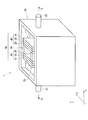
- FIG. 1 is a schematic perspective view showing an example of a microbial fuel cell according to an embodiment of the present invention.
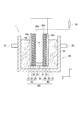
- FIG. 2 is a sectional view taken along line AA in FIG.
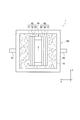
- FIG. 3 is a schematic plan view showing an example of the microbial fuel cell according to the embodiment of the present invention.
- FIG. 4 is an exploded perspective view showing a fuel cell unit in the microbial fuel cell.
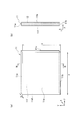
- Fig.5 (a) is a perspective view which shows an example of the carbon material which comprises the negative electrode in the said microbial fuel cell.
- FIG. 5B is a cross-sectional view taken along the line BB in FIG.
- FIG. 6A is a perspective view showing another example of the carbon material constituting the negative electrode in the microbial fuel cell.
- FIG. 1 is a schematic perspective view showing an example of a microbial fuel cell according to an embodiment of the present invention.
- FIG. 2 is a sectional view taken along line AA in FIG.
- FIG. 3 is a schematic plan view
- FIG. 6B is a cross-sectional view taken along the line CC in FIG.
- FIG. 7 is a schematic view showing an example of the shape of the through hole provided in the carbon material.
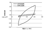
- FIG. 8 is a graph showing the evaluation results by cyclic voltammetry for the test pieces of the reference example and the reference comparative example.
- FIG. 9 is a graph showing the relationship between the power density and the current density in the microbial fuel cells of Example 1 and Comparative Example 1.
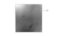
- FIG. 10 is a photograph showing a graphite sheet having an exposed surface area of 0.36 cm 2 / cm 3 and an aperture ratio of 0% in Example 2.
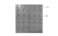
- FIG. 11 is a photograph showing a graphite sheet having an exposed surface area of 0.38 cm 2 / cm 3 and an aperture ratio of 0.3% in Example 2.
- FIG. 10 is a photograph showing a graphite sheet having an exposed surface area of 0.38 cm 2 / cm 3 and an aperture ratio of 0.3% in Example 2.
- FIG. 12 is a photograph showing a graphite sheet having an exposed surface area of 0.48 cm 2 / cm 3 and an aperture ratio of 1.3% in Example 2.
- FIG. 13 is a photograph showing a graphite sheet having an exposed surface area of 0.82 cm 2 / cm 3 and an aperture ratio of 5.1% in Example 2.
- FIG. 14 is a photograph showing a graphite sheet having an exposed surface area of 1.26 cm 2 / cm 3 and an aperture ratio of 10% in Example 2.
- FIG. 15 is a photograph showing a graphite sheet having an exposed surface area of 2.32 cm 2 / cm 3 and an aperture ratio of 22% in Example 2.
- FIG. 16 is a photograph showing a graphite sheet having an exposed surface area of 1.07 cm 2 / cm 3 and an aperture ratio of 42% in Example 2.
- FIG. 17 is a photograph showing a graphite sheet having an exposed surface area of 0.81 cm 2 / cm 3 and an aperture ratio of 68% in Example 2.
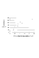
- FIG. 18 is a graph showing the relationship between the average steady output and the exposed surface area in the microbial fuel cell of Example 2.
- the microbial fuel cell 1 includes a plurality of electrode assemblies 40 including a negative electrode 10, a positive electrode 20, and an ion transfer layer 30.
- the negative electrode 10 is disposed so as to contact one surface 30 a of the ion moving layer 30, and the positive electrode is formed on the surface 30 b opposite to the surface 30 a of the ion moving layer 30. It arrange
- the two electrode assemblies 40 are laminated via the cassette base material 50 so that the positive electrodes 20 face each other.
- the cassette base material 50 is a U-shaped frame member along the outer peripheral portion of the surface 20a of the positive electrode 20, and the upper portion is open. That is, the cassette base material 50 is a frame member in which the bottom surfaces of the two first columnar members 51 are connected by the second columnar member 52.
- the side surface 53 of the cassette base material 50 is joined to the outer peripheral portion of the surface 20 a of the positive electrode 20. Can be prevented from leaking.
- stacking the electrode assembly 40 of 2 sheets and the cassette base material 50 is formed so that the gaseous phase 2 connected with air
- An electrolyte solution 70 is held inside the waste water tank 80, and the negative electrode 10, the positive electrode 20, and the ion transfer layer 30 are immersed in the electrolyte solution 70.
- the positive electrode 20 includes a water-repellent layer 21 having water repellency. Therefore, the electrolytic solution 70 held in the waste water tank 80 is separated from the inside of the cassette base material 50, and the internal space formed by the two electrode assemblies 40 and the cassette base material 50 is the gas phase 2. It has become. As shown in FIG. 2, the negative electrode 10 and the positive electrode 20 are each electrically connected to the external circuit 90.
- the negative electrode 10 in the present embodiment includes a sheet-like carbon material 11 formed by laminating a plurality of graphenes.
- the graphene 12 is stacked along the thickness direction (X direction) of the carbon material 11, and the carbon hexagonal mesh surface of the graphene is the surface direction of the carbon material 11. They are arranged along (YZ direction). And since graphene has a strong bond between carbons, the carbon material 11 has high conductivity in the surface direction (YZ direction) while having high corrosion resistance.
- the carbon material 11 is preferably a graphite sheet.
- the graphite sheet is obtained by processing graphite into a sheet shape, has high corrosion resistance, and has an electrical resistivity equivalent to that of a metal material, and thus has both durability and conductivity.
- Such a graphite sheet can be obtained, for example, as follows. First, natural graphite is chemically treated with an acid to form an insert between the graphene 12 layers of graphite. Next, when this is rapidly heated at a high temperature, expanded graphite in which the space between the graphenes is pushed and expanded by the gas pressure due to the thermal decomposition of the interlayer insert is obtained. Then, the expanded graphite is pressurized and roll-rolled to obtain a graphite sheet.
- the graphene in the graphite is arranged along a plane direction (YZ direction) perpendicular to the thickness direction (X direction). Yes. Therefore, it becomes possible to increase the electrical conductivity between the carbon material 11 and the external circuit 90 and to further improve the efficiency of the battery reaction. Moreover, since a space
- the carbon material 11 may be used independently as a negative electrode material, you may use it by laminating
- the other material is not particularly limited, but may be a conductive porous material such as carbon felt or metal mesh, or an insulating porous material such as woven fabric or nonwoven fabric.
- An anaerobic microorganism is held in the negative electrode 10, and hydrogen ions and electrons are generated from at least one of the organic substance and the nitrogen-containing compound in the electrolytic solution 70 by the catalytic action of the microorganism.
- the negative electrode 10 has one surface 10 a and the other surface 10 b opposite to the one surface 10 a, and the one surface 10 a forms the ion moving layer 30.
- the anaerobic microorganisms are held on the other surface 10b while facing the positive electrode 20 through the other side.
- the anaerobic microorganisms are held in the negative electrode 10 by stacking and fixing the biofilm containing the anaerobic microorganisms on the other surface 10 b of the negative electrode 10.
- the biofilm generally refers to a three-dimensional structure including a microbial population and an extracellular polymeric substance (EPS) produced by the microbial population.
- EPS extracellular polymeric substance
- the anaerobic microorganisms may be held on the negative electrode 10 regardless of the biofilm.
- the anaerobic microorganisms may be held not only on the surface of the negative electrode 10 but also inside.
- the anaerobic microorganism held in the negative electrode 10 is preferably, for example, an electricity producing bacterium having an extracellular electron transfer mechanism.
- examples of the anaerobic microorganism include Geobacter genus bacteria, Shewanella genus bacteria, Aeromonas genus bacteria, Geothrix genus bacteria, and Saccharomyces genus bacteria.
- the area of the exposed surface along the stacking direction X of the graphene 12 in the carbon material 11 ([area of exposed surface] / [volume of the carbon material]) with respect to the volume of the carbon material 11 is. 1.0 ⁇ 10 ⁇ 5 to 20 cm 2 / cm 3 .
- the “volume of the carbon material 11” can be obtained by multiplying the thickness x, the length y, and the width z of the carbon material 11 as shown in FIG.
- the surface exposed outside along the lamination direction X of the graphene 12 in the carbon material 11 is called "exposed surface". That is, in the carbon material 11 shown in FIG.
- the upper surface 11a, the lower surface 11b, the right side surface 11c, and the left side surface 11d are referred to as exposed surfaces.
- the area of the exposed surface is referred to as “exposed surface area”, and the area of the exposed surface can be obtained from the thickness x, the length y, and the width z of the carbon material 11. That is, the exposed surface areas of the upper surface 11a and the lower surface 11b can be obtained by multiplying the thickness x and the width z, and the exposed surface areas of the right side surface 11c and the left side surface 11d are multiplied by the thickness x and the length y. Can be obtained.
- the laminated surface of the graphene 12 is exposed on the exposed surface of the carbon material 11. Therefore, when an anaerobic microorganism is carried on the exposed surface, electrons generated by the action of the anaerobic microorganism are conducted to the end of the graphene 12 existing inside the carbon material 11, and the carbon hexagonal network surface of the graphene 12. To the external circuit 90. That is, as the exposed surface of the carbon material 11 increases, the electron conductivity from the anaerobic microorganisms to the graphene 12 increases, so that the output of the microbial fuel cell 1 can be improved.
- the area of the exposed surface with respect to the volume of the carbon material 11 ([area of exposed surface] / [volume of carbon material]) is 1.0 ⁇ 10 ⁇ 5 cm 2 / cm 3 or more, the electron conductivity by the exposed surface The improvement effect can be obtained. Moreover, when the area of the exposed surface with respect to the volume of the carbon material 11 is 20 cm 2 / cm 3 or less, as described later, the size and number of through holes for increasing the exposed surface may be set to appropriate values. Therefore, the strength of the carbon material 11 can be maintained.
- the area of the exposed surface along the stacking direction X of the graphene 12 in the carbon material 11 with respect to the volume of the carbon material 11 is more preferably 0.4 to 7 cm 2 / cm 3 .
- the area of the exposed surface with respect to the volume of the carbon material 11 is 0.4 cm 2 / cm 3 or more, since the amount of anaerobic microorganisms supported on the exposed surface increases, it becomes possible to further increase the electron conductivity. .
- the area of the exposed surface with respect to the volume of the carbon material 11 is 7 cm 2 / cm 3 or less, it is possible to maintain high strength while improving the electronic conductivity of the carbon material 11.
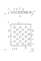
- the negative electrode 10 preferably has a through-hole 13 along the stacking direction X of graphene.
- the exposed surface of the carbon material 11 increases, so that the contact rate between the graphene 12 lamination surface and anaerobic microorganisms increases, and the output of the microbial fuel cell 1 can be further improved. It becomes.
- the exposed surface area indicates the total area of the inner surfaces 13a of the through holes 13 in addition to the areas of the upper surface 11a, the lower surface 11b, the right side surface 11c, and the left side surface 11d.
- the shape of the through-hole 13 is not particularly limited, and can be a round hole penetrating along the graphene stacking direction X as shown in FIG.
- the exposed surface area of the through hole 13 can be obtained by multiplying the circumferential length of the through hole 13 by the thickness x of the carbon material 11.
- the shape of the through hole 13 is at least one selected from the group consisting of a round hole, a square hole, a hexagonal hole, a long round hole, a long square hole, a diamond hole, a round cross hole, and a cross hole. can do.
- sequence of a through-hole can be made into a 60 degree zigzag type, a square zigzag type, or a parallel type.
- the through hole 13 can be formed by punching the carbon material 11.
- the through holes 13 are preferably formed at substantially uniform intervals in the plane direction (YZ direction) of the carbon material 11. Since the interval between the adjacent through-holes 13 is substantially constant, anaerobic microorganisms are likely to be supported substantially uniformly on the surface 11e (YZ surface in FIG. 6) and the exposed surface of the carbon material 11, and thus in the electrolytic solution 70. It becomes possible to improve the decomposition efficiency of organic substances and nitrogen-containing compounds.
- the opening ratio of the carbon material 11 having the through holes 13 is preferably 1 to 70%.
- the opening ratio of the carbon material 11 is 1% or more, hydrogen ions generated on the surface 10b of the negative electrode 10 shown in FIG. 2 easily pass through the through hole 13 and reach the positive electrode 20, so that an oxygen reduction reaction is performed. It is possible to promote and improve the output of the microbial fuel cell 1.
- the aperture ratio of the carbon material 11 is 70% or less, it is possible to suppress a decrease in strength of the carbon material 11.
- the through hole 13 is a 60 ° staggered round hole shown in FIG. 7, the aperture ratio can be obtained by the following formula (1).
- the carbon material 11 is provided with the through-hole 13 penetrating completely along the stacking direction X of the graphene 12.
- the carbon material 11 is not limited to the through hole 13, and the carbon material 11 may increase the exposed surface by providing a recess that does not completely penetrate along the stacking direction X of the graphene 12.
- a recessed part can be formed by, for example, partially penetrating the surface 11e of the carbon material 11.
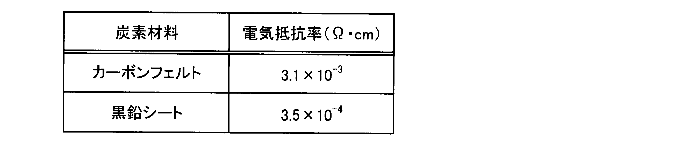
- Table 1 shows an example of the electrical resistivity of the surface (YZ plane in FIG. 5) of the carbon felt that is a graphite sheet and a nonwoven fabric.
- these electrical resistivity is the value measured by the four probe method.
- the carbon-based nonwoven material described in Patent Document 1 has a high contact resistance, and thus has an electric resistivity 10 times that of the graphite sheet.
- Such a high electrical resistivity leads to an increase in internal resistance of the microbial fuel cell, that is, a decrease in output. Therefore, by using a graphite sheet as the carbon material 11, the internal resistance of the microbial fuel cell can be reduced and the output can be increased.
- the negative electrode 10 may be modified with, for example, an electron transfer mediator molecule.
- the electrolytic solution 70 in the waste water tank 80 may contain electron transfer mediator molecules. Thereby, the electron transfer from an anaerobic microorganism to the negative electrode 10 is accelerated
- an electron transfer mediator molecule is not particularly limited.
- at least one selected from the group consisting of neutral red, anthraquinone-2,6-disulfonic acid (AQDS), thionine, potassium ferricyanide, and methylviologen is used. Can do.
- the positive electrode 20 in the present embodiment has a function of generating water by reacting oxygen supplied from the gas phase 2 with hydrogen ions and electrons generated in the negative electrode 10.
- the positive electrode 20 of the present embodiment is not particularly limited as long as it has such a configuration, but for example, as shown in FIG. 2, at least a water repellent layer 21 and a gas diffusion layer 22 may be provided. preferable.
- the water repellent layer 21 is a layer having both water repellency and gas permeability.
- the water repellent layer 21 is configured to allow gas movement from the gas phase 2 to the electrolyte solution 70 while favorably separating the gas phase 2 and the electrolyte solution 70 in the electrochemical system in the microbial fuel cell 1.
- the water repellent layer 21 is configured to transmit oxygen in the gas phase 2 and move it to the gas diffusion layer 22.
- Such a water repellent layer 21 is preferably porous. In this case, the water repellent layer 21 can have high gas permeability.
- the gas diffusion layer 22 preferably includes, for example, a porous conductive material and a catalyst supported on the conductive material.
- the gas diffusion layer 22 may be composed of a porous and conductive catalyst.
- the water repellent layer 21 in the positive electrode 20 is provided on the gas phase 2 side.
- the surface 20 a of the water repellent layer 21 opposite to the gas diffusion layer 22 is exposed to the gas phase 2. Accordingly, oxygen in the gas phase is supplied to the gas diffusion layer 22 through the water repellent layer 21.
- the gas diffusion layer 22 in the positive electrode 20 is in contact with the ion moving layer 30 so as to face the negative electrode 10 with the ion moving layer 30 interposed therebetween.
- the water repellent layer 21 is preferably a porous body having water repellency.
- the water repellent layer 21 can have high gas permeability.
- Such a water-repellent layer 21 may be made of, for example, one or more materials selected from the group consisting of polytetrafluoroethylene (PTFE), dimethylpolysiloxane (PDMS), polyethylene (PE), and polypropylene (PP). preferable.
- the water repellent layer 21 is preferably bonded to the gas diffusion layer 22 via an adhesive.
- the adhesive is preferably provided on at least a part between the water-repellent layer 21 and the gas diffusion layer 22 from the viewpoint of securing the adhesiveness between the water-repellent layer 21 and the gas diffusion layer 22.
- the adhesive is made of the water repellent layer 21 and the gas diffusion layer. More preferably, it is provided on the entire surface between the two.
- the adhesive preferably has oxygen permeability, and includes at least one selected from the group consisting of polymethyl methacrylate, methacrylic acid-styrene copolymer, styrene-butadiene rubber, butyl rubber, nitrile rubber, chloroprene rubber, and silicone. Resin can be used.
- the gas diffusion layer 22 preferably includes, for example, a porous conductive material and a catalyst supported on the conductive material.
- the gas diffusion layer 22 may be composed of a porous and conductive catalyst.
- the conductive material in the gas diffusion layer 22 can be composed of, for example, one or more materials selected from the group consisting of carbon-based substances, conductive polymers, semiconductors, and metals.
- the carbon-based material means a material containing carbon as a constituent component.
- Examples of carbon-based materials include, for example, carbon powder such as graphite, activated carbon, carbon black, Vulcan (registered trademark) XC-72R, acetylene black, furnace black, Denka black, graphite felt, carbon wool, carbon woven cloth, etc. Examples include carbon fiber, carbon plate, carbon paper, and carbon disk.
- Examples of the carbon-based material also include fine-structured materials such as carbon nanotubes, carbon nanohorns, and carbon nanoclusters.
- Conductive polymer is a general term for conductive polymer compounds.
- the conductive polymer for example, a single monomer or a polymer of two or more monomers having aniline, aminophenol, diaminophenol, pyrrole, thiophene, paraphenylene, fluorene, furan, acetylene, or a derivative thereof as a structural unit.
- examples of the conductive polymer include polyaniline, polyaminophenol, polydiaminophenol, polypyrrole, polythiophene, polyparaphenylene, polyfluorene, polyfuran, and polyacetylene.
- An example of the metal conductive material is a stainless mesh. In consideration of availability, cost, corrosion resistance, durability, and the like, the conductive material is preferably a carbon-based substance.
- the shape of the conductive material is preferably a powder shape or a fiber shape. Further, the conductive material may be supported by a support.
- the support is a member that itself has rigidity and can give the gas diffusion layer 22 a certain shape.
- the support may be an insulator or a conductor.
- examples of the support include glass, plastic, synthetic rubber, ceramics, water- or water-repellent treated paper, plant pieces such as wood pieces, animal pieces such as bone pieces, and shells. It is done.
- Examples of the porous structure support include porous ceramics, porous plastics, and sponges.
- the support When the support is a conductor, examples of the support include carbon-based materials such as carbon paper, carbon fiber, and carbon rod, metals, conductive polymers, and the like.
- the support When the support is a conductor, the support can also function as a current collector by disposing a conductive material carrying a carbon-based material, which will be described later, on the surface of the support.
- the catalyst in the gas diffusion layer 22 is preferably an oxygen reduction catalyst.
- the catalyst may be supported on the surface of the gas diffusion layer 22 and inside the pores using a binder. Thereby, it can suppress that a catalyst detach
- a binder is not particularly limited as long as particles can be bound to each other.
- the binder for example, at least one selected from the group consisting of polytetrafluoroethylene (PTFE), polyvinylidene fluoride (PVDF), ethylene-propylene-diene copolymer (EPDM) and Nafion is preferably used.
- the oxygen reduction catalyst is preferably a carbon-based material doped with metal atoms.
- the metal atom is not particularly limited, but titanium, vanadium, chromium, manganese, iron, cobalt, nickel, copper, zirconium, niobium, molybdenum, ruthenium, rhodium, palladium, silver, hafnium, tantalum, tungsten, rhenium, osmium, iridium It is preferably an atom of at least one metal selected from the group consisting of platinum, and gold.
- the carbon-based material exhibits excellent performance as a catalyst for promoting the oxygen reduction reaction. What is necessary is just to set suitably the quantity of the metal atom which carbonaceous material contains so that carbonaceous material may have the outstanding catalyst performance.
- the carbon-based material is further doped with one or more nonmetallic atoms selected from nitrogen, boron, sulfur, and phosphorus. What is necessary is just to set suitably the quantity of the nonmetallic atom doped by the carbonaceous material so that carbonaceous material may have the outstanding catalyst performance.
- the carbon-based material is based on a carbon source material such as graphite and amorphous carbon, for example, and the carbon source material is doped with a metal atom and one or more non-metal atoms selected from nitrogen, boron, sulfur and phosphorus. Can be obtained.
- a carbon source material such as graphite and amorphous carbon, for example, and the carbon source material is doped with a metal atom and one or more non-metal atoms selected from nitrogen, boron, sulfur and phosphorus. Can be obtained.
- the combination of metal atoms and nonmetal atoms doped in the carbon-based material is appropriately selected.
- the nonmetallic atom contains nitrogen and the metallic atom contains iron.
- the carbonaceous material can have a particularly excellent catalytic activity.
- the nonmetallic atom may be only nitrogen. Further, the metal atom may be only iron.
- the nonmetallic atom may contain nitrogen, and the metallic atom may contain at least one of cobalt and manganese. Also in this case, the carbon-based material can have a particularly excellent catalytic activity.
- the nonmetallic atom may be only nitrogen. Further, the metal atom may be only cobalt, only manganese, or only cobalt and manganese.
- a carbon-based material configured as an oxygen reduction catalyst can be prepared as follows. First, for example, a mixture containing a nonmetallic compound containing at least one nonmetal selected from the group consisting of nitrogen, boron, sulfur, and phosphorus, a metal compound, and a carbon source material is prepared. And this mixture is heated at the temperature of 800 degreeC or more and 1000 degrees C or less for 45 second or more and less than 600 second. Thereby, the carbonaceous material comprised as an oxygen reduction catalyst can be obtained.
- the carbon source material for example, graphite or amorphous carbon can be used as described above.
- the metal compound is not particularly limited as long as it is a compound containing a metal atom capable of coordinating with a nonmetal atom doped in the carbon source material.
- Metal compounds include, for example, metal chlorides, nitrates, sulfates, bromides, iodides, fluorides, etc .; inorganic metal salts such as acetates; inorganic metal salt hydrates; and organic metal salts At least one selected from the group consisting of hydrates can be used.
- the metal compound preferably contains iron (III) chloride.
- the metal compound when graphite is doped with cobalt, the metal compound preferably contains cobalt chloride.
- the metal compound when the carbon source material is doped with manganese, the metal compound preferably contains manganese acetate.
- the amount of the metal compound used is preferably set so that, for example, the ratio of the metal atom in the metal compound to the carbon source material is in the range of 5 to 30% by mass, and this ratio is in the range of 5 to 20% by mass. It is more preferable to set so as to be within.
- the nonmetallic compound is preferably at least one nonmetallic compound selected from the group consisting of nitrogen, boron, sulfur and phosphorus.
- Non-metallic compounds include, for example, pentaethylenehexamine, ethylenediamine, tetraethylenepentamine, triethylenetetramine, ethylenediamine, octylboronic acid, 1,2-bis (diethylphosphinoethane), triphenyl phosphite, benzyldisal
- At least one compound selected from the group consisting of fido can be used.
- the amount of the nonmetallic compound used is appropriately set according to the amount of the nonmetallic atom doped into the carbon source material.
- the amount of the nonmetallic compound used is preferably set so that the molar ratio of the metal atom in the metal compound to the nonmetallic atom in the nonmetallic compound is within the range of 1: 1 to 1: 2. : It is more preferable to set it within the range of 1.5 to 1: 1.8.
- a mixture containing a nonmetallic compound, a metal compound, and a carbon source material when preparing a carbon-based material configured as an oxygen reduction catalyst is obtained, for example, as follows. First, a carbon source material, a metal compound, and a nonmetal compound are mixed, and if necessary, a solvent such as ethanol is added to adjust the total amount. These are further dispersed by an ultrasonic dispersion method. Subsequently, after heating them at an appropriate temperature (for example, 60 ° C.), the mixture is dried to remove the solvent. Thereby, the mixture containing a nonmetallic compound, a metal compound, and a carbon source raw material is obtained.
- the obtained mixture is heated, for example, under a reducing atmosphere or an inert gas atmosphere.
- a non-metallic atom is doped to a carbon source raw material, and also a metallic atom is doped by the coordinate bond of a non-metallic atom and a metallic atom.
- the heating temperature is preferably in the range of 800 ° C. to 1000 ° C.
- the heating time is preferably in the range of 45 seconds to less than 600 seconds. Since the heating time is short, the carbon-based material is efficiently produced, and the catalytic activity of the carbon-based material is further increased.
- the temperature rising rate of the mixture at the start of heating is preferably 50 ° C./s or more. Such rapid heating further improves the catalytic activity of the carbon-based material.
- the carbon-based material may be further acid cleaned.
- the carbon-based material may be dispersed in pure water with a homogenizer for 30 minutes, and then the carbon-based material may be placed in 2M sulfuric acid and stirred at 80 ° C. for 3 hours. In this case, elution of the metal component from the carbon-based material can be suppressed.
- the microbial fuel cell 1 of the present embodiment preferably further includes an ion moving layer provided between the negative electrode 10 and the positive electrode 20 and having hydrogen ion permeability. As shown in FIGS. 1 to 4, the negative electrode 10 is separated from the positive electrode 20 with an ion transfer layer 30 interposed therebetween.
- the ion moving layer 30 has a function of transmitting hydrogen ions generated in the negative electrode 10 and moving the hydrogen ions to the positive electrode 20 side.
- an ion exchange membrane using an ion exchange resin can be used as the ion moving layer 30, for example.
- an ion exchange membrane using an ion exchange resin for example, NAFION (registered trademark) manufactured by DuPont, and Flemion (registered trademark) and Selemion (registered trademark) manufactured by Asahi Glass Co., Ltd. can be used.
- the ion moving layer 30 a porous film having pores capable of permeating hydrogen ions may be used. That is, the ion moving layer 30 may be a sheet having a space (void) for moving hydrogen ions between the negative electrode 10 and the positive electrode 20. Therefore, the ion migration layer 30 preferably includes at least one selected from the group consisting of a porous sheet, a woven sheet, and a nonwoven sheet. Moreover, the ion migration layer 30 can use at least one chosen from the group which consists of a glass fiber membrane, a synthetic fiber membrane, and a plastic nonwoven fabric, and the laminated body formed by laminating these two or more may be used. Since such a porous sheet has a large number of pores inside, hydrogen ions can easily move. The pore diameter of the ion moving layer 30 is not particularly limited as long as hydrogen ions can move from the negative electrode 10 to the positive electrode 20.
- the ion transfer layer 30 has a function of transmitting hydrogen ions generated in the negative electrode 10 and moving them to the positive electrode 20 side. Further, for example, if the negative electrode 10 and the positive electrode 20 are close to each other without being in contact with each other, hydrogen ions can move from the negative electrode 10 to the positive electrode 20. Therefore, in the microbial fuel cell 1 of the present embodiment, the ion moving layer 30 is not an essential component. However, since the provision of the ion moving layer 30 enables efficient movement of hydrogen ions from the negative electrode 10 to the positive electrode 20, it is preferable to provide the ion moving layer 30 from the viewpoint of improving the output.
- the negative electrode 10 contains at least one of an organic substance and a nitrogen-containing compound
- the electrolytic solution 70 that is a liquid to be treated is supplied
- the positive electrode 20 is supplied with a gas containing air or oxygen.
- the air is continuously supplied through an opening provided in the upper part of the cassette base material 50.
- the electrolyte solution 70 is also continuously supplied through the waste water supply port 81 and the waste water discharge port 82.
- the positive electrode 20 air diffuses through the water repellent layer 21 and passes through the gas diffusion layer 22.
- hydrogen ions and electrons are generated from at least one of the organic substance and the nitrogen-containing compound in the electrolytic solution 70 by the catalytic action of microorganisms.
- the generated hydrogen ions pass through the ion moving layer 30 and move to the positive electrode 20 side.
- the generated electrons move to the external circuit 90 through the carbon material 11 of the negative electrode 10, and further move from the external circuit 90 to the gas diffusion layer 22 of the positive electrode 20.
- the hydrogen ions and electrons moved to the gas diffusion layer 22 are combined with oxygen by the action of the catalyst and consumed as water. At this time, the electric energy flowing in the closed circuit is recovered by the external circuit 90.
- the microbial fuel cell 1 includes the negative electrode 10 made of the carbon material 11 in which a plurality of graphenes 12 are stacked, and the positive electrode 20 facing the negative electrode 10.
- the negative electrode 10 and the positive electrode 20 are immersed in the electrolytic solution, and at least a part of the positive electrode 20 is exposed to the gas phase 2.
- the area of the exposed surface along the stacking direction X of the graphene 12 in the carbon material 11 with respect to the volume of the carbon material 11 is 1.0 ⁇ 10 ⁇ 5 to 20 cm 2 / cm 3 .
- the conductivity in the direction (YZ direction) perpendicular to the stacking direction X of the graphenes 12 can be increased.
- action of the anaerobic microorganism becomes easy to be conducted by the graphene 12, Therefore The output of the microbial fuel cell 1 is improved. It becomes possible to make it.
- the negative electrode 10 preferably has a through-hole 13 along the stacking direction X of graphene.
- the through hole 13 is particularly effective in the configuration in which the negative electrode 10, the ion migration layer 30, and the positive electrode 20 are stacked as shown in FIGS. 1 to 3. That is, by providing the through hole 13, hydrogen ions generated on the surface 10 b of the negative electrode 10 and the exposed surface inside the through hole 13 can easily move to the ion moving layer 30 and the positive electrode 20 through the through hole 13. Therefore, the conductivity of hydrogen ions can be improved and the efficiency of the oxygen reduction reaction can be increased.
- the upper surface 11a, the lower surface 11b, the right side surface 11c, and the left side surface 11d of the carbon material 11 may be corrugated.
- the fuel cell unit 60 shown in FIGS. 1 to 4 has a structure in which two electrode assemblies 40 and a cassette substrate 50 are stacked.
- the present embodiment is not limited to this configuration.
- the electrode assembly 40 may be bonded to only one side surface 53 of the cassette base material 50 and the other side surface may be sealed with a plate member.
- the cassette base material 50 may be partially opened or closed as long as air (oxygen) can be introduced therein.
- the waste water tank 80 holds the electrolytic solution 70 therein, but may be configured such that the electrolytic solution 70 circulates.
- the wastewater tank 80 has a wastewater supply port 81 for supplying the electrolyte solution 70 to the wastewater tank 80 and a wastewater tank 80 for discharging the treated electrolyte solution 70 from the wastewater tank 80.
- the waste water discharge port 82 may be provided.
- the inside of the wastewater tank 80 is maintained under anaerobic conditions in which, for example, molecular oxygen is not present or even if molecular oxygen is present, the concentration thereof is extremely small. Thereby, it becomes possible to hold
- the test piece of the reference example which exposed only the exposed surface along the lamination direction X of the graphene 12 was produced by masking the surface 11e and back surface 11f parallel to the YZ plane in the graphite sheet.
- the graphite sheet Carbofit (registered trademark) manufactured by Hitachi Chemical Co., Ltd. was used.
- test piece of the reference comparative example which exposed only the surface 11e and the back surface 11f parallel to a YZ plane by masking the upper surface 11a, the lower surface 11b, the right side surface 11c, and the left side surface 11d parallel to the X-axis in a graphite sheet. was made.
- the negative electrode of this example was produced as follows. First, by opening a plurality of holes of ⁇ 5mm the graphite sheet, to the volume of graphite sheet, the area of the exposed surface along the lamination direction of the graphene and 1.63cm 2 / cm 3, YZ plane parallel front and back surfaces of the The area was 50.7 cm 2 / cm 3 . And it was set as the negative electrode of this example by adhere
- the graphite sheet used was a carbofit manufactured by Hitachi Chemical.
- As the conductive epoxy resin a conductive epoxy adhesive CW2400 manufactured by Circuit Works was used.
- the positive electrode of this example was produced by supporting an oxygen reduction catalyst on the graphite sheet used in the negative electrode. Specifically, it was prepared by dropping a dispersion of an oxygen reduction catalyst onto a graphite sheet and drying it.
- the oxygen reduction catalyst was prepared as follows. First, 3 g of carbon black, 0.1 M iron (III) chloride aqueous solution, and 0.15 M pentaethylenehexamine ethanol solution were placed in a container to prepare a mixed solution. As carbon black, Ketjen Black ECP600JD manufactured by Lion Specialty Chemicals Co., Ltd. was used. The amount of 0.1M iron (III) chloride aqueous solution used was adjusted so that the ratio of iron atoms to carbon black was 10% by mass. The total amount was adjusted to 9 mL by adding ethanol to the mixture. And this liquid mixture was ultrasonically disperse
- this sample was packed into one end of a quartz tube, and then the inside of this quartz tube was replaced with argon.
- the quartz tube was pulled out 45 seconds after being placed in a furnace at 900 ° C.
- the quartz tube was inserted into the furnace over 3 seconds to adjust the rate of temperature rise of the sample at the start of heating to 300 ° C./s.
- the sample was cooled by flowing argon gas through the quartz tube.
- the oxygen reduction catalyst dispersion was prepared by mixing 0.35 g of a powdery oxygen reduction catalyst, 0.35 mL of PTFE dispersion, and 2 mL of ion-exchanged water.
- a microbial fuel cell was produced using the negative electrode and the positive electrode obtained as described above.
- the microbial fuel cell of this example was set in the waste water tank without using an ion moving layer as shown in FIG. 1 with a space of about 5 mm between the negative electrode and the positive electrode.
- a model waste liquid having a total organic carbon (TOC) of 800 mg / L was used, and the liquid temperature was 30 ° C.
- sodium hydrogen carbonate was added to the electrolyte so as to be 5 mM as a buffer.
- the capacity of the waste water tank was 300 cc.
- the amount of inflow into the wastewater tank was adjusted so that the hydraulic retention time of the electrolyte was 24 hours.
- the obtained microbial fuel cell was operated for 1-2 weeks, and the change in output characteristics was examined.
- the evaluation results are shown in FIG. As shown in FIG. 9, the maximum output of the fuel cell of this example was 350 mW / m 2 , and good output characteristics were obtained.
- the negative electrode of this example was produced as follows. First, the same graphite sheet as in Example 1 is not subjected to hole opening treatment, and the upper surface, the lower surface, the right side surface, and the left side surface parallel to the X-axis of the graphite sheet are masked, whereby the front surface and the rear surface parallel to the YZ plane Only exposed. Thereby, the area of the exposed surface along the stacking direction of the graphene with respect to the volume of the graphite sheet was set to 0 cm 2 / cm 3, and the area of the front and back surfaces parallel to the YZ plane was set to 58.4 cm 2 / cm 3 . Then, in the same manner as in Example 1, an electric wire was bonded to the end portion of the obtained graphite sheet using a conductive epoxy resin to obtain a negative electrode of this example.
- Example 2 the same positive electrode, electrolyte solution, and waste water tank as Example 1 were used, and the microbial fuel cell of this example was produced like Example 1.
- the obtained microbial fuel cell was operated for 1 to 2 weeks in the same manner as in Example 1, and the change in output characteristics was examined. As shown in FIG. 9, the maximum output of the fuel cell of this example is 300 mW / m 2 , which is worse than that of Example 1.
- the total area of the exposed surface in the negative electrode of Example 1 and the area of the surface parallel to the YZ plane and the back surface is 52.33 cm 2 / cm 3 , but the area of the exposed surface in the negative electrode of Comparative Example 1 and YZ
- the total area of the front and back surfaces parallel to the surface is 58.4 cm 2 / cm 3 . That is, although the total area of the negative electrode of Example 1 was smaller than that of Comparative Example 1, the microbial fuel cell of Example 1 had good output characteristics. From this, it can be seen that the exposed surface is more excellent in the conductivity of electrons generated by anaerobic microorganisms than the surface parallel to the YZ plane and the back surface of the negative electrode.
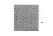
- Example 2 The negative electrode of this example was produced as follows. First, a graphite sheet having a length of 9 cm and a width of 8.5 cm was prepared. Next, a plurality of negative electrodes having different exposed surface areas and different aperture ratios were prepared by adjusting the number and size of the through holes in the graphite sheet.
- FIG. 10 shows a graphite sheet having an exposed surface area of 0.36 cm 2 / cm 3 and an aperture ratio of 0%.
- FIG. 11 shows a graphite sheet having an exposed surface area of 0.38 cm 2 / cm 3 and an aperture ratio of 0.3%.
- FIG. 12 shows a graphite sheet having an exposed surface area of 0.48 cm 2 / cm 3 and an aperture ratio of 1.3%.
- FIG. 10 shows a graphite sheet having an exposed surface area of 0.36 cm 2 / cm 3 and an aperture ratio of 0%.
- FIG. 11 shows a graphite sheet having an exposed surface area of 0.38 cm 2 / cm 3 and an aperture ratio of 0.3%.
- FIG. 12
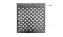
- FIG. 13 shows a graphite sheet having an exposed surface area of 0.82 cm 2 / cm 3 and an aperture ratio of 5.1%.
- FIG. 14 shows a graphite sheet having an exposed surface area of 1.26 cm 2 / cm 3 and an aperture ratio of 10%.
- FIG. 15 shows a graphite sheet having an exposed surface area of 2.32 cm 2 / cm 3 and an aperture ratio of 22%.
- FIG. 16 shows a graphite sheet having an exposed surface area of 1.07 cm 2 / cm 3 and an aperture ratio of 42%.
- FIG. 17 shows a graphite sheet having an exposed surface area of 0.81 cm 2 / cm 3 and an aperture ratio of 68%.
- the graphite sheet used was a carbofit manufactured by Hitachi Chemical.
- a conductive epoxy adhesive CW2400 manufactured by CircuitCWorks was used as the conductive epoxy resin.
- Example 2 a microbial fuel cell of this example was produced in the same manner as in Example 1.
- the obtained microbial fuel cell was operated for 1 to 2 weeks in the same manner as in Example 1, and the change in output characteristics was examined.
- the measurement results are shown in Table 2 and FIG.
- the present embodiment has been described above, the present embodiment is not limited to these, and various modifications are possible within the scope of the gist of the present embodiment.
- the negative electrode 10, the positive electrode 20, and the ion transfer layer 30 are formed in a rectangular shape.
- these shapes are not particularly limited, and can be arbitrarily changed depending on the size of the fuel cell and the desired power generation performance. Further, the area of each layer can be arbitrarily changed as long as a desired function can be exhibited.
- a microbial fuel cell capable of increasing the conductivity of the electrode and improving the output by power generation.
Abstract
A microbial fuel cell (1) comprises: a negative electrode (10) which is formed from a carbon material (11) obtained by laminating a plurality of graphenes (12), and in which the area of the surface exposed along the graphene layering direction (X) of the carbon material is 1.0 x 10⁻⁵ to 20 cm2/cm3 in terms of the carbon material volume; and a positive electrode (20) opposing the negative electrode. The negative electrode and positive electrode are immersed in an electrolyte (70) and at least a portion of the positive electrode is exposed to a gas phase (2).
Description
本発明は、微生物燃料電池に関する。詳細には本発明は、廃水を浄化し、かつ、電気エネルギーを生成することが可能な微生物燃料電池に関する。
The present invention relates to a microbial fuel cell. In particular, the present invention relates to a microbial fuel cell capable of purifying waste water and generating electrical energy.
近年、持続可能なエネルギーとして、バイオマスを利用して発電をする微生物燃料電池が注目されている。微生物燃料電池は、微生物の代謝能力を利用して有機物などを電気エネルギーに変換する装置であり、有機物の処理をしながらエネルギーの回収ができるという優れたシステムである。ただ、微生物が発する電力が非常に小さく、出力される電流密度が低いため、更なる改良が必要である。
In recent years, microbial fuel cells that generate electricity using biomass have attracted attention as sustainable energy. A microbial fuel cell is an apparatus that converts organic matter into electrical energy by utilizing the metabolic ability of microorganisms, and is an excellent system that can recover energy while processing organic matter. However, since the power generated by microorganisms is very small and the output current density is low, further improvement is necessary.
このような微生物燃料電池として、微生物付着量を増やす電極を備えたものが開示されている(特許文献1参照)。特許文献1では、電極基板内部又はその表面に、平均孔径が最も大きい孔の平均孔径が50μm<Rmax≦1.5cmであり、かつ、平均孔径が最も小さい孔の平均孔径が10μm<Rmin≦50μmである少なくとも2種の孔を有する電極が開示されている。また、電極基板として、セルロース不織布を焼成して炭素化したものを用いることも開示されている。
Such a microbial fuel cell has been disclosed that includes an electrode that increases the amount of microbial adhesion (see Patent Document 1). In Patent Document 1, an average hole diameter of a hole having the largest average hole diameter is 50 μm <Rmax ≦ 1.5 cm and an average hole diameter of a hole having the smallest average hole diameter is 10 μm <Rmin ≦ 50 μm inside or on the surface of the electrode substrate. An electrode having at least two types of holes is disclosed. It is also disclosed to use a carbonized non-woven cellulose fabric as an electrode substrate.
しかしながら、特許文献1の電極基板は不織布からなるため、炭素繊維同士の接点が多く、導電性が低いことから、微生物燃料電池の出力が低下する恐れがあった。
However, since the electrode substrate of Patent Document 1 is made of non-woven fabric, there are many contact points between carbon fibers, and the conductivity is low, which may reduce the output of the microbial fuel cell.
本発明は、このような従来技術の有する課題に鑑みてなされたものである。そして、本発明の目的は、電極の導電性を高め、発電による出力を向上させることが可能な微生物燃料電池を提供することにある。
The present invention has been made in view of such problems of the conventional technology. And the objective of this invention is providing the microbial fuel cell which can improve the electroconductivity of an electrode and can improve the output by electric power generation.
上記課題を解決するために、本発明の態様に係る微生物燃料電池は、複数のグラフェンが積層した炭素材料からなり、炭素材料の体積に対する、炭素材料におけるグラフェンの積層方向に沿った露出表面の面積が1.0×10⁻⁵~20cm2/cm3である負極と、負極と対向する正極と、を有する。そして、負極及び正極が電解液に浸漬し、正極の少なくとも一部が気相に露出する。
In order to solve the above problems, a microbial fuel cell according to an aspect of the present invention is composed of a carbon material in which a plurality of graphenes are stacked, and the exposed surface area along the stacking direction of graphene in the carbon material with respect to the volume of the carbon material. Has a negative electrode with 1.0 × 10 −5 to 20 cm 2 / cm 3 and a positive electrode facing the negative electrode. And a negative electrode and a positive electrode are immersed in electrolyte solution, and at least one part of a positive electrode is exposed to a gaseous phase.
以下、本実施形態に係る微生物燃料電池について詳細に説明する。なお、図面の寸法比率は説明の都合上誇張されており、実際の比率とは異なる場合がある。
Hereinafter, the microbial fuel cell according to the present embodiment will be described in detail. In addition, the dimension ratio of drawing is exaggerated on account of description, and may differ from an actual ratio.
[微生物燃料電池]
図1乃至図3に示すように、本実施形態に係る微生物燃料電池1は、負極10、正極20及びイオン移動層30からなる複数の電極接合体40を備えている。微生物燃料電池1では、図2に示すように、イオン移動層30の一方の面30aに負極10が接触するように配置されており、イオン移動層30の面30aと反対側の面30bに正極20が接触するように配置されている。 [Microbial fuel cell]
As shown in FIGS. 1 to 3, themicrobial fuel cell 1 according to this embodiment includes a plurality of electrode assemblies 40 including a negative electrode 10, a positive electrode 20, and an ion transfer layer 30. In the microbial fuel cell 1, as shown in FIG. 2, the negative electrode 10 is disposed so as to contact one surface 30 a of the ion moving layer 30, and the positive electrode is formed on the surface 30 b opposite to the surface 30 a of the ion moving layer 30. It arrange | positions so that 20 may contact.
図1乃至図3に示すように、本実施形態に係る微生物燃料電池1は、負極10、正極20及びイオン移動層30からなる複数の電極接合体40を備えている。微生物燃料電池1では、図2に示すように、イオン移動層30の一方の面30aに負極10が接触するように配置されており、イオン移動層30の面30aと反対側の面30bに正極20が接触するように配置されている。 [Microbial fuel cell]
As shown in FIGS. 1 to 3, the
さらに図4に示すように、2枚の電極接合体40は、正極20同士が対向するように、カセット基材50を介して積層されている。カセット基材50は、正極20における面20aの外周部に沿うU字状の枠部材であり、上部が開口している。つまり、カセット基材50は、2本の第一柱状部材51の底面を第二柱状部材52で連結した枠部材である。そして、カセット基材50の側面53は、正極20の面20aの外周部と接合されており、正極20の面20aの外周部からカセット基材50の内部に、被処理液である電解液70が漏出することを抑制できる。
Further, as shown in FIG. 4, the two electrode assemblies 40 are laminated via the cassette base material 50 so that the positive electrodes 20 face each other. The cassette base material 50 is a U-shaped frame member along the outer peripheral portion of the surface 20a of the positive electrode 20, and the upper portion is open. That is, the cassette base material 50 is a frame member in which the bottom surfaces of the two first columnar members 51 are connected by the second columnar member 52. The side surface 53 of the cassette base material 50 is joined to the outer peripheral portion of the surface 20 a of the positive electrode 20. Can be prevented from leaking.
そして、図2及び図3に示すように、2枚の電極接合体40とカセット基材50とを積層してなる燃料電池ユニット60は、大気と連通した気相2が形成されるように、廃水槽80の内部に配置される。廃水槽80の内部には電解液70が保持されており、負極10、正極20及びイオン移動層30は、電解液70に浸漬されている。
And as shown in FIG.2 and FIG.3, the fuel cell unit 60 formed by laminating | stacking the electrode assembly 40 of 2 sheets and the cassette base material 50 is formed so that the gaseous phase 2 connected with air | atmosphere may be formed. It is arranged inside the waste water tank 80. An electrolyte solution 70 is held inside the waste water tank 80, and the negative electrode 10, the positive electrode 20, and the ion transfer layer 30 are immersed in the electrolyte solution 70.
後述のように、正極20は、撥水性を有する撥水層21を備えている。そのため、廃水槽80の内部に保持された電解液70とカセット基材50の内部とは隔てられ、2枚の電極接合体40とカセット基材50とにより形成された内部空間は気相2となっている。そして、図2に示すように、負極10及び正極20は、それぞれ外部回路90と電気的に接続されている。
As described later, the positive electrode 20 includes a water-repellent layer 21 having water repellency. Therefore, the electrolytic solution 70 held in the waste water tank 80 is separated from the inside of the cassette base material 50, and the internal space formed by the two electrode assemblies 40 and the cassette base material 50 is the gas phase 2. It has become. As shown in FIG. 2, the negative electrode 10 and the positive electrode 20 are each electrically connected to the external circuit 90.
(負極)
本実施形態における負極10は、図5(a)に示すように、複数のグラフェンが積層してなるシート状の炭素材料11を有している。図5(b)に示すように、炭素材料11において、グラフェン12は炭素材料11の厚さ方向(X方向)に沿って積層されており、グラフェンの炭素六角網面が炭素材料11の面方向(YZ方向)に沿って配列している。そして、グラフェンは炭素同士の結合が強いことから、炭素材料11は高耐食性を備えつつも、面方向(YZ方向)に高い導電性を有している。 (Negative electrode)
As shown in FIG. 5A, thenegative electrode 10 in the present embodiment includes a sheet-like carbon material 11 formed by laminating a plurality of graphenes. As shown in FIG. 5B, in the carbon material 11, the graphene 12 is stacked along the thickness direction (X direction) of the carbon material 11, and the carbon hexagonal mesh surface of the graphene is the surface direction of the carbon material 11. They are arranged along (YZ direction). And since graphene has a strong bond between carbons, the carbon material 11 has high conductivity in the surface direction (YZ direction) while having high corrosion resistance.
本実施形態における負極10は、図5(a)に示すように、複数のグラフェンが積層してなるシート状の炭素材料11を有している。図5(b)に示すように、炭素材料11において、グラフェン12は炭素材料11の厚さ方向(X方向)に沿って積層されており、グラフェンの炭素六角網面が炭素材料11の面方向(YZ方向)に沿って配列している。そして、グラフェンは炭素同士の結合が強いことから、炭素材料11は高耐食性を備えつつも、面方向(YZ方向)に高い導電性を有している。 (Negative electrode)
As shown in FIG. 5A, the
炭素材料11は黒鉛シートであることが好ましい。黒鉛シートは、黒鉛をシート状に加工したものであり、高い耐食性を有し、かつ、電気抵抗率が金属材料と同等であるため、耐久性と導電性を両立している。このような黒鉛シートは、例えば、次のようにして得ることができる。まず、天然黒鉛を酸によって化学処理を施し、黒鉛のグラフェン12の層間へ挿入物を形成させる。次に、これを高温で急速加熱することで、層間挿入物の熱分解によるガス圧でグラフェン間が押し広がった膨張黒鉛が得られる。そして、この膨張黒鉛を加圧し、ロール圧延することにより、黒鉛シートが得られる。このようにして得られた黒鉛シートを用いた場合、図5(b)に示すように、黒鉛におけるグラフェンが厚さ方向(X方向)に垂直な面方向(YZ方向)に沿って配列している。そのため、炭素材料11と外部回路90との間の導電性を高め、電池反応の効率をより向上させることが可能となる。また、グラフェン12の層間に空隙が存在するため、黒鉛シートは可撓性を有している。なお、負極材料として炭素材料11を単独で使用してもよいが、他の材料と積層あるいは複合させて使用してもよい。他の材料は特に限定されないが、カーボンフェルトや金属メッシュなどの導電性の多孔質材料でもよく、織布や不織布などの絶縁性の多孔質材料でもよい。
The carbon material 11 is preferably a graphite sheet. The graphite sheet is obtained by processing graphite into a sheet shape, has high corrosion resistance, and has an electrical resistivity equivalent to that of a metal material, and thus has both durability and conductivity. Such a graphite sheet can be obtained, for example, as follows. First, natural graphite is chemically treated with an acid to form an insert between the graphene 12 layers of graphite. Next, when this is rapidly heated at a high temperature, expanded graphite in which the space between the graphenes is pushed and expanded by the gas pressure due to the thermal decomposition of the interlayer insert is obtained. Then, the expanded graphite is pressurized and roll-rolled to obtain a graphite sheet. When the graphite sheet thus obtained is used, as shown in FIG. 5 (b), the graphene in the graphite is arranged along a plane direction (YZ direction) perpendicular to the thickness direction (X direction). Yes. Therefore, it becomes possible to increase the electrical conductivity between the carbon material 11 and the external circuit 90 and to further improve the efficiency of the battery reaction. Moreover, since a space | gap exists between the layers of the graphene 12, a graphite sheet has flexibility. In addition, although the carbon material 11 may be used independently as a negative electrode material, you may use it by laminating | stacking or combining with another material. The other material is not particularly limited, but may be a conductive porous material such as carbon felt or metal mesh, or an insulating porous material such as woven fabric or nonwoven fabric.
負極10には嫌気性微生物が保持され、当該微生物の触媒作用により、電解液70中の有機物及び窒素含有化合物の少なくとも一方から水素イオン及び電子を生成している。具体的には、図2に示すように、負極10は、一方の面10aと、当該一方の面10aと反対側の他方の面10bとを有し、一方の面10aがイオン移動層30を介して正極20と対向し、他方の面10b上に嫌気性微生物が保持されている。つまり、負極10における他方の面10b上に嫌気性微生物を含むバイオフィルムが重ねられて固定されることで、負極10に嫌気性微生物が保持される。なお、バイオフィルムとは、一般に、微生物集団と、微生物集団が生産する菌体外重合体物質(extracellular polymeric substance、EPS)とを含む三次元構造体のことをいう。ただ、嫌気性微生物は、バイオフィルムによらずに負極10に保持されていてもよい。また、嫌気性微生物は、負極10表面だけでなく、内部に保持されていてもよい。
An anaerobic microorganism is held in the negative electrode 10, and hydrogen ions and electrons are generated from at least one of the organic substance and the nitrogen-containing compound in the electrolytic solution 70 by the catalytic action of the microorganism. Specifically, as shown in FIG. 2, the negative electrode 10 has one surface 10 a and the other surface 10 b opposite to the one surface 10 a, and the one surface 10 a forms the ion moving layer 30. The anaerobic microorganisms are held on the other surface 10b while facing the positive electrode 20 through the other side. That is, the anaerobic microorganisms are held in the negative electrode 10 by stacking and fixing the biofilm containing the anaerobic microorganisms on the other surface 10 b of the negative electrode 10. The biofilm generally refers to a three-dimensional structure including a microbial population and an extracellular polymeric substance (EPS) produced by the microbial population. However, the anaerobic microorganisms may be held on the negative electrode 10 regardless of the biofilm. In addition, the anaerobic microorganisms may be held not only on the surface of the negative electrode 10 but also inside.
負極10に保持される嫌気性微生物は、例えば細胞外電子伝達機構を有する電気生産細菌であることが好ましい。具体的には、嫌気性微生物として、例えばGeobacter属細菌、Shewanella属細菌、Aeromonas属細菌、Geothrix属細菌、Saccharomyces属細菌が挙げられる。
The anaerobic microorganism held in the negative electrode 10 is preferably, for example, an electricity producing bacterium having an extracellular electron transfer mechanism. Specifically, examples of the anaerobic microorganism include Geobacter genus bacteria, Shewanella genus bacteria, Aeromonas genus bacteria, Geothrix genus bacteria, and Saccharomyces genus bacteria.
そして、本実施形態の負極10において、炭素材料11の体積に対する、炭素材料11におけるグラフェン12の積層方向Xに沿った露出表面の面積([露出表面の面積]/[炭素材料の体積])が1.0×10-5~20cm2/cm3である。「炭素材料11の体積」は、図5(a)に示すように、炭素材料11の厚さx、長さy及び幅zを乗算することにより求めることができる。そして、本明細書において、炭素材料11におけるグラフェン12の積層方向Xに沿って、外部に露出した面を「露出表面」という。つまり、図5(a)に示す炭素材料11では、上面11a、下面11b、右側面11c及び左側面11dを露出表面という。そして、露出表面の面積を「露出表面積」といい、露出表面の面積は炭素材料11の厚さx、長さy及び幅zから求めることができる。つまり、上面11a及び下面11bの露出表面積は厚さxと幅zとを乗算することにより求めることができ、右側面11c及び左側面11dの露出表面積は厚さxと長さyとを乗算することにより求めることができる。
In the negative electrode 10 of this embodiment, the area of the exposed surface along the stacking direction X of the graphene 12 in the carbon material 11 ([area of exposed surface] / [volume of the carbon material]) with respect to the volume of the carbon material 11 is. 1.0 × 10 −5 to 20 cm 2 / cm 3 . The “volume of the carbon material 11” can be obtained by multiplying the thickness x, the length y, and the width z of the carbon material 11 as shown in FIG. And in this specification, the surface exposed outside along the lamination direction X of the graphene 12 in the carbon material 11 is called "exposed surface". That is, in the carbon material 11 shown in FIG. 5A, the upper surface 11a, the lower surface 11b, the right side surface 11c, and the left side surface 11d are referred to as exposed surfaces. The area of the exposed surface is referred to as “exposed surface area”, and the area of the exposed surface can be obtained from the thickness x, the length y, and the width z of the carbon material 11. That is, the exposed surface areas of the upper surface 11a and the lower surface 11b can be obtained by multiplying the thickness x and the width z, and the exposed surface areas of the right side surface 11c and the left side surface 11d are multiplied by the thickness x and the length y. Can be obtained.
負極10において、炭素材料11の露出表面ではグラフェン12の積層面が露出している。そのため、露出表面に嫌気性微生物が担持されている場合、嫌気性微生物の作用により生成した電子が、炭素材料11の内部に存在するグラフェン12の端部に伝導し、グラフェン12の炭素六角網面を通じて外部回路90まで到達することができる。つまり、炭素材料11の露出表面が多いほど、嫌気性微生物からグラフェン12への電子伝導性が高まるため、微生物燃料電池1の出力を向上させることが可能となる。
In the negative electrode 10, the laminated surface of the graphene 12 is exposed on the exposed surface of the carbon material 11. Therefore, when an anaerobic microorganism is carried on the exposed surface, electrons generated by the action of the anaerobic microorganism are conducted to the end of the graphene 12 existing inside the carbon material 11, and the carbon hexagonal network surface of the graphene 12. To the external circuit 90. That is, as the exposed surface of the carbon material 11 increases, the electron conductivity from the anaerobic microorganisms to the graphene 12 increases, so that the output of the microbial fuel cell 1 can be improved.
炭素材料11の体積に対する露出表面の面積([露出表面の面積]/[炭素材料の体積])が1.0×10-5cm2/cm3以上の場合には、露出表面による電子伝導性の向上効果を得ることが可能となる。また、炭素材料11の体積に対する露出表面の面積が20cm2/cm3以下の場合には、後述のように、露出表面を増やすための貫通孔の大きさや数などを適切な値にすることができるため、炭素材料11の強度を維持することが可能となる。
When the area of the exposed surface with respect to the volume of the carbon material 11 ([area of exposed surface] / [volume of carbon material]) is 1.0 × 10 −5 cm 2 / cm 3 or more, the electron conductivity by the exposed surface The improvement effect can be obtained. Moreover, when the area of the exposed surface with respect to the volume of the carbon material 11 is 20 cm 2 / cm 3 or less, as described later, the size and number of through holes for increasing the exposed surface may be set to appropriate values. Therefore, the strength of the carbon material 11 can be maintained.
負極10において、炭素材料11の体積に対する、炭素材料11におけるグラフェン12の積層方向Xに沿った露出表面の面積が0.4~7cm2/cm3であることがより好ましい。炭素材料11の体積に対する露出表面の面積が0.4cm2/cm3以上であることにより、露出表面への嫌気性微生物の担持量が増加するため、電子伝導性をより高めることが可能となる。また、炭素材料11の体積に対する露出表面の面積が7cm2/cm3以下であることにより、炭素材料11の電子伝導性を向上させつつも、高い強度を維持することが可能となる。
In the negative electrode 10, the area of the exposed surface along the stacking direction X of the graphene 12 in the carbon material 11 with respect to the volume of the carbon material 11 is more preferably 0.4 to 7 cm 2 / cm 3 . When the area of the exposed surface with respect to the volume of the carbon material 11 is 0.4 cm 2 / cm 3 or more, since the amount of anaerobic microorganisms supported on the exposed surface increases, it becomes possible to further increase the electron conductivity. . Moreover, when the area of the exposed surface with respect to the volume of the carbon material 11 is 7 cm 2 / cm 3 or less, it is possible to maintain high strength while improving the electronic conductivity of the carbon material 11.
図6に示すように、負極10は、グラフェンの積層方向Xに沿った貫通孔13を有することが好ましい。貫通孔13を形成することにより、炭素材料11の露出表面が増加するため、グラフェン12の積層面と嫌気性微生物との接触率が増加し、微生物燃料電池1の出力をより向上させることが可能となる。なお、炭素材料11が貫通孔13を有する場合、露出表面積は、上面11a、下面11b、右側面11c及び左側面11dの面積に加えて、貫通孔13の内面13aの面積の合計を指す。
As shown in FIG. 6, the negative electrode 10 preferably has a through-hole 13 along the stacking direction X of graphene. By forming the through holes 13, the exposed surface of the carbon material 11 increases, so that the contact rate between the graphene 12 lamination surface and anaerobic microorganisms increases, and the output of the microbial fuel cell 1 can be further improved. It becomes. When the carbon material 11 has the through holes 13, the exposed surface area indicates the total area of the inner surfaces 13a of the through holes 13 in addition to the areas of the upper surface 11a, the lower surface 11b, the right side surface 11c, and the left side surface 11d.
貫通孔13の形状は特に限定されず、図6に示すように、グラフェンの積層方向Xに沿って貫通した丸孔とすることができる。なお、貫通孔13の形状が丸孔の場合、貫通孔13の露出表面積は貫通孔13の円周の長さと炭素材料11の厚さxとを乗算することにより求めることができる。
The shape of the through-hole 13 is not particularly limited, and can be a round hole penetrating along the graphene stacking direction X as shown in FIG. When the shape of the through hole 13 is a round hole, the exposed surface area of the through hole 13 can be obtained by multiplying the circumferential length of the through hole 13 by the thickness x of the carbon material 11.
図7に示すように、貫通孔13の形状は、丸孔、角孔、六角形孔、長丸孔、長角孔、菱孔、丸十文字孔及び十文字孔からなる群より選ばれる少なくとも一つとすることができる。また、貫通孔の配列は、60°千鳥型、角千鳥型又は並列型とすることができる。なお、貫通孔13は、炭素材料11に対して打ち抜き加工を施すことで形成することができる。
As shown in FIG. 7, the shape of the through hole 13 is at least one selected from the group consisting of a round hole, a square hole, a hexagonal hole, a long round hole, a long square hole, a diamond hole, a round cross hole, and a cross hole. can do. Moreover, the arrangement | sequence of a through-hole can be made into a 60 degree zigzag type, a square zigzag type, or a parallel type. The through hole 13 can be formed by punching the carbon material 11.
貫通孔13は、図7に示すように、炭素材料11の面方向(YZ方向)に略均一な間隔で形成されることが好ましい。隣接する貫通孔13の間隔が略一定であることにより、嫌気性微生物が炭素材料11の表面11e(図6中のYZ面)及び露出表面に略均一に担持されやすくなるため、電解液70中の有機物及び窒素含有化合物の分解効率を高めることが可能となる。
As shown in FIG. 7, the through holes 13 are preferably formed at substantially uniform intervals in the plane direction (YZ direction) of the carbon material 11. Since the interval between the adjacent through-holes 13 is substantially constant, anaerobic microorganisms are likely to be supported substantially uniformly on the surface 11e (YZ surface in FIG. 6) and the exposed surface of the carbon material 11, and thus in the electrolytic solution 70. It becomes possible to improve the decomposition efficiency of organic substances and nitrogen-containing compounds.
負極10において、貫通孔13を有する炭素材料11の開口率は1~70%であることが好ましい。炭素材料11の開口率が1%以上の場合には、図2に示す負極10の面10bで生成した水素イオンが貫通孔13を通過して正極20まで到達しやすくなるため、酸素還元反応を促進し、微生物燃料電池1の出力を向上させることが可能となる。炭素材料11の開口率が70%以下の場合には、炭素材料11の強度低下を抑制することが可能となる。なお、例えば、貫通孔13が図7に示す60°千鳥型の丸孔の場合には、開口率は次の数式(1)で求めることができる。また、貫通孔13が図7に示す60°千鳥型の六角形孔の場合には、開口率は次の数式(2)で求めることができる。
開口率(%)=90.6×D2/P2 (1)
開口率(%)=W2/P2×100 (2) In thenegative electrode 10, the opening ratio of the carbon material 11 having the through holes 13 is preferably 1 to 70%. When the opening ratio of the carbon material 11 is 1% or more, hydrogen ions generated on the surface 10b of the negative electrode 10 shown in FIG. 2 easily pass through the through hole 13 and reach the positive electrode 20, so that an oxygen reduction reaction is performed. It is possible to promote and improve the output of the microbial fuel cell 1. When the aperture ratio of the carbon material 11 is 70% or less, it is possible to suppress a decrease in strength of the carbon material 11. For example, when the through hole 13 is a 60 ° staggered round hole shown in FIG. 7, the aperture ratio can be obtained by the following formula (1). When the through hole 13 is a 60 ° staggered hexagonal hole shown in FIG. 7, the aperture ratio can be obtained by the following mathematical formula (2).
Opening ratio (%) = 90.6 × D 2 / P 2 (1)
Opening ratio (%) = W 2 / P 2 × 100 (2)
開口率(%)=90.6×D2/P2 (1)
開口率(%)=W2/P2×100 (2) In the
Opening ratio (%) = 90.6 × D 2 / P 2 (1)
Opening ratio (%) = W 2 / P 2 × 100 (2)
上述のように、炭素材料11は、グラフェン12の積層方向Xに沿って完全に貫通した貫通孔13を設けることが好ましい。ただ、貫通孔13に限定されず、炭素材料11は、グラフェン12の積層方向Xに沿って完全に貫通していない凹部を設けることにより、露出表面を増加させてもよい。なお、凹部は、例えば炭素材料11の表面11eを部分的にくり貫くことにより、形成することができる。
As described above, it is preferable that the carbon material 11 is provided with the through-hole 13 penetrating completely along the stacking direction X of the graphene 12. However, the carbon material 11 is not limited to the through hole 13, and the carbon material 11 may increase the exposed surface by providing a recess that does not completely penetrate along the stacking direction X of the graphene 12. In addition, a recessed part can be formed by, for example, partially penetrating the surface 11e of the carbon material 11.
ここで表1では、黒鉛シート及び不織布であるカーボンフェルトにおける表面(図5中のYZ面)の電気抵抗率の一例を示している。なお、これらの電気抵抗率は四端子法により測定した値である。表1に示すように、特許文献1に記載されているような炭素系の不織布材料は接触抵抗が高いことから、黒鉛シートに比べての10倍の電気抵抗率を有している。このような高い電気抵抗率は、微生物燃料電池の内部抵抗の増加、つまり出力の低下へと繋がってしまう。そのため、炭素材料11として黒鉛シートを用いることにより、微生物燃料電池の内部抵抗を減少させ、出力を高めることが可能となる。
Here, Table 1 shows an example of the electrical resistivity of the surface (YZ plane in FIG. 5) of the carbon felt that is a graphite sheet and a nonwoven fabric. In addition, these electrical resistivity is the value measured by the four probe method. As shown in Table 1, the carbon-based nonwoven material described in Patent Document 1 has a high contact resistance, and thus has an electric resistivity 10 times that of the graphite sheet. Such a high electrical resistivity leads to an increase in internal resistance of the microbial fuel cell, that is, a decrease in output. Therefore, by using a graphite sheet as the carbon material 11, the internal resistance of the microbial fuel cell can be reduced and the output can be increased.
本実施形態に係る負極10には、例えば、電子伝達メディエーター分子が修飾されていてもよい。あるいは、廃水槽80内の電解液70は、電子伝達メディエーター分子を含んでいてもよい。これにより、嫌気性微生物から負極10への電子移動を促進し、より効率的な廃水処理を実現できる。
The negative electrode 10 according to the present embodiment may be modified with, for example, an electron transfer mediator molecule. Alternatively, the electrolytic solution 70 in the waste water tank 80 may contain electron transfer mediator molecules. Thereby, the electron transfer from an anaerobic microorganism to the negative electrode 10 is accelerated | stimulated, and more efficient waste water treatment is realizable.
具体的には、嫌気性微生物による代謝機構では、細胞内又は最終電子受容体との間で電子の授受が行われる。電解液70中にメディエーター分子を導入すると、メディエーター分子が代謝の最終電子受容体として作用し、かつ、受け取った電子を負極10へと受け渡す。この結果、電解液70における有機物などの酸化分解速度を高めることが可能になる。このような電子伝達メディエーター分子は、特に限定されないが、例えばニュートラルレッド、アントラキノン-2,6-ジスルホン酸(AQDS)、チオニン、フェリシアン化カリウム、及びメチルビオローゲンからなる群より選ばれる少なくとも一つを用いることができる。
Specifically, in the metabolic mechanism by anaerobic microorganisms, electrons are transferred between cells or with the final electron acceptor. When a mediator molecule is introduced into the electrolytic solution 70, the mediator molecule acts as a final electron acceptor of metabolism, and delivers received electrons to the negative electrode 10. As a result, it becomes possible to increase the rate of oxidative decomposition of the organic matter in the electrolytic solution 70. Such an electron transfer mediator molecule is not particularly limited. For example, at least one selected from the group consisting of neutral red, anthraquinone-2,6-disulfonic acid (AQDS), thionine, potassium ferricyanide, and methylviologen is used. Can do.
(正極)
本実施形態における正極20は、気相2から供給される酸素と、負極10で生成した水素イオン及び電子と反応させ、水を生成する作用を有する。そのため、本実施形態の正極20は、このような作用を生じさせる構成ならば特に限定されないが、例えば図2に示すように、少なくとも撥水層21及びガス拡散層22を備える構成とすることが好ましい。 (Positive electrode)
Thepositive electrode 20 in the present embodiment has a function of generating water by reacting oxygen supplied from the gas phase 2 with hydrogen ions and electrons generated in the negative electrode 10. For this reason, the positive electrode 20 of the present embodiment is not particularly limited as long as it has such a configuration, but for example, as shown in FIG. 2, at least a water repellent layer 21 and a gas diffusion layer 22 may be provided. preferable.
本実施形態における正極20は、気相2から供給される酸素と、負極10で生成した水素イオン及び電子と反応させ、水を生成する作用を有する。そのため、本実施形態の正極20は、このような作用を生じさせる構成ならば特に限定されないが、例えば図2に示すように、少なくとも撥水層21及びガス拡散層22を備える構成とすることが好ましい。 (Positive electrode)
The
撥水層21は、撥水性と気体透過性とを併せ持つ層である。撥水層21は、微生物燃料電池1における電気化学系中の気相2と電解液70とを良好に分離しながら、気相2から電解液70へ向かう気体の移動を許容するように構成される。つまり、撥水層21は、気相2中における酸素を透過し、ガス拡散層22へ移動させるように構成されている。このような撥水層21は、多孔質であることが好ましい。この場合、撥水層21は、高い気体透過性を有することができる。
The water repellent layer 21 is a layer having both water repellency and gas permeability. The water repellent layer 21 is configured to allow gas movement from the gas phase 2 to the electrolyte solution 70 while favorably separating the gas phase 2 and the electrolyte solution 70 in the electrochemical system in the microbial fuel cell 1. The That is, the water repellent layer 21 is configured to transmit oxygen in the gas phase 2 and move it to the gas diffusion layer 22. Such a water repellent layer 21 is preferably porous. In this case, the water repellent layer 21 can have high gas permeability.
ガス拡散層22は、例えば多孔質な導電性材料と、この導電性材料に担持されている触媒とを備えることが好ましい。なお、ガス拡散層22が、多孔質かつ導電性を有する触媒から構成されてもよい。
The gas diffusion layer 22 preferably includes, for example, a porous conductive material and a catalyst supported on the conductive material. The gas diffusion layer 22 may be composed of a porous and conductive catalyst.
本実施形態では、正極20における撥水層21が気相2側に設けられている。そして、撥水層21の、ガス拡散層22とは反対側の面20aは気相2に露出している。これより、撥水層21を通じて、気相中の酸素がガス拡散層22へ供給される。また、正極20におけるガス拡散層22は、イオン移動層30を介して負極10と対向するように、イオン移動層30と接触している。
In this embodiment, the water repellent layer 21 in the positive electrode 20 is provided on the gas phase 2 side. The surface 20 a of the water repellent layer 21 opposite to the gas diffusion layer 22 is exposed to the gas phase 2. Accordingly, oxygen in the gas phase is supplied to the gas diffusion layer 22 through the water repellent layer 21. Further, the gas diffusion layer 22 in the positive electrode 20 is in contact with the ion moving layer 30 so as to face the negative electrode 10 with the ion moving layer 30 interposed therebetween.
より詳細に説明すると、撥水層21は、撥水性を有した多孔質体であることが好ましい。この場合、撥水層21は、高い気体透過性を有することができる。このような撥水層21は、例えばポリテトラフルオロエチレン(PTFE)、ジメチルポリシロキサン(PDMS)、ポリエチレン(PE)及びポリプロピレン(PP)からなる群より選ばれる一種以上の材料から作製されることが好ましい。
More specifically, the water repellent layer 21 is preferably a porous body having water repellency. In this case, the water repellent layer 21 can have high gas permeability. Such a water-repellent layer 21 may be made of, for example, one or more materials selected from the group consisting of polytetrafluoroethylene (PTFE), dimethylpolysiloxane (PDMS), polyethylene (PE), and polypropylene (PP). preferable.
正極20において、ガス拡散層22に効率的に酸素を供給するために、撥水層21は、接着剤を介してガス拡散層22と接合していることが好ましい。これにより、ガス拡散層22に対し、拡散した酸素が直接供給され、酸素還元反応を効率的に行うことができる。接着剤は、撥水層21とガス拡散層22との間の接着性を確保する観点から、撥水層21とガス拡散層22との間の少なくとも一部に設けられていることが好ましい。ただ、撥水層21とガス拡散層22との間の接着性を高め、長期間に亘り安定的に酸素をガス拡散層22に供給する観点から、接着剤は撥水層21とガス拡散層22との間の全面に設けられていることがより好ましい。
In the positive electrode 20, in order to efficiently supply oxygen to the gas diffusion layer 22, the water repellent layer 21 is preferably bonded to the gas diffusion layer 22 via an adhesive. Thereby, the diffused oxygen is directly supplied to the gas diffusion layer 22, and the oxygen reduction reaction can be performed efficiently. The adhesive is preferably provided on at least a part between the water-repellent layer 21 and the gas diffusion layer 22 from the viewpoint of securing the adhesiveness between the water-repellent layer 21 and the gas diffusion layer 22. However, from the viewpoint of improving the adhesion between the water repellent layer 21 and the gas diffusion layer 22 and supplying oxygen to the gas diffusion layer 22 stably over a long period of time, the adhesive is made of the water repellent layer 21 and the gas diffusion layer. More preferably, it is provided on the entire surface between the two.
接着剤としては酸素透過性を有するものが好ましく、ポリメチルメタクリレート、メタクリル酸-スチレン共重合体、スチレン-ブタジエンゴム、ブチルゴム、ニトリルゴム、クロロプレンゴム及びシリコーンからなる群より選ばれる少なくとも一つを含む樹脂を用いることができる。
The adhesive preferably has oxygen permeability, and includes at least one selected from the group consisting of polymethyl methacrylate, methacrylic acid-styrene copolymer, styrene-butadiene rubber, butyl rubber, nitrile rubber, chloroprene rubber, and silicone. Resin can be used.
ガス拡散層22は、例えば多孔質な導電性材料と、この導電性材料に担持されている触媒とを備えることが好ましい。なお、ガス拡散層22が、多孔質かつ導電性を有する触媒から構成されてもよい。
The gas diffusion layer 22 preferably includes, for example, a porous conductive material and a catalyst supported on the conductive material. The gas diffusion layer 22 may be composed of a porous and conductive catalyst.
ガス拡散層22における導電性材料は、例えば炭素系物質、導電性ポリマー、半導体及び金属からなる群より選ばれる一種以上の材料から構成することができる。ここで、炭素系物質とは、炭素を構成成分とする物質をいう。炭素系物質の例としては、例えば、グラファイト、活性炭、カーボンブラック、バルカン(登録商標)XC-72R、アセチレンブラック、ファーネスブラック、デンカブラックなどのカーボンパウダー、グラファイトフェルト、カーボンウール、カーボン織布などのカーボンファイバー、カーボンプレート、カーボンペーパー、及びカーボンディスクが挙げられる。また、炭素系物質の例として、カーボンナノチューブ、カーボンナノホーン、カーボンナノクラスターのような微細構造物質も挙げられる。
The conductive material in the gas diffusion layer 22 can be composed of, for example, one or more materials selected from the group consisting of carbon-based substances, conductive polymers, semiconductors, and metals. Here, the carbon-based material means a material containing carbon as a constituent component. Examples of carbon-based materials include, for example, carbon powder such as graphite, activated carbon, carbon black, Vulcan (registered trademark) XC-72R, acetylene black, furnace black, Denka black, graphite felt, carbon wool, carbon woven cloth, etc. Examples include carbon fiber, carbon plate, carbon paper, and carbon disk. Examples of the carbon-based material also include fine-structured materials such as carbon nanotubes, carbon nanohorns, and carbon nanoclusters.
導電性ポリマーとは、導電性を有する高分子化合物の総称である。導電性ポリマーとしては、例えば、アニリン、アミノフェノール、ジアミノフェノール、ピロール、チオフェン、パラフェニレン、フルオレン、フラン、アセチレン若しくはそれらの誘導体を構成単位とする単一モノマー又は二種以上のモノマーの重合体が挙げられる。具体的には、導電性ポリマーとして、例えば、ポリアニリン、ポリアミノフェノール、ポリジアミノフェノール、ポリピロール、ポリチオフェン、ポリパラフェニレン、ポリフルオレン、ポリフラン、ポリアセチレン等が挙げられる。金属製の導電性材料としては、例えば、ステンレスメッシュが挙げられる。入手の容易性、コスト、耐食性、耐久性等を考慮した場合、導電性材料は炭素系物質であることが好ましい。
Conductive polymer is a general term for conductive polymer compounds. As the conductive polymer, for example, a single monomer or a polymer of two or more monomers having aniline, aminophenol, diaminophenol, pyrrole, thiophene, paraphenylene, fluorene, furan, acetylene, or a derivative thereof as a structural unit. Can be mentioned. Specifically, examples of the conductive polymer include polyaniline, polyaminophenol, polydiaminophenol, polypyrrole, polythiophene, polyparaphenylene, polyfluorene, polyfuran, and polyacetylene. An example of the metal conductive material is a stainless mesh. In consideration of availability, cost, corrosion resistance, durability, and the like, the conductive material is preferably a carbon-based substance.
また、導電性材料の形状は、粉末形状又は繊維形状であることが好ましい。また、導電性材料は、支持体に支持されていてもよい。支持体とは、それ自身が剛性を有し、ガス拡散層22に一定の形状を付与することのできる部材をいう。支持体は絶縁体であっても導電体であってもよい。支持体が絶縁体である場合、支持体としては、例えば、ガラス、プラスチック、合成ゴム、セラミックス、耐水又は撥水処理した紙、木片などの植物片、骨片、貝殻などの動物片等が挙げられる。多孔質構造の支持体としては、例えば、多孔質セラミック、多孔質プラスチック、スポンジ等が挙げられる。支持体が導電体である場合、支持体としては、例えば、カーボンペーパー、カーボンファイバー、炭素棒などの炭素系物質、金属、導電性ポリマー等が挙げられる。支持体が導電体の場合には、後述する炭素系材料を担持した導電性材料が支持体の表面上に配置されることで、支持体が集電体としても機能し得る。
The shape of the conductive material is preferably a powder shape or a fiber shape. Further, the conductive material may be supported by a support. The support is a member that itself has rigidity and can give the gas diffusion layer 22 a certain shape. The support may be an insulator or a conductor. When the support is an insulator, examples of the support include glass, plastic, synthetic rubber, ceramics, water- or water-repellent treated paper, plant pieces such as wood pieces, animal pieces such as bone pieces, and shells. It is done. Examples of the porous structure support include porous ceramics, porous plastics, and sponges. When the support is a conductor, examples of the support include carbon-based materials such as carbon paper, carbon fiber, and carbon rod, metals, conductive polymers, and the like. When the support is a conductor, the support can also function as a current collector by disposing a conductive material carrying a carbon-based material, which will be described later, on the surface of the support.
ガス拡散層22における触媒は、酸素還元触媒であることが好ましい。また、触媒は、結着剤を用いてガス拡散層22の表面及び細孔内部に担持されていてもよい。これにより、触媒がガス拡散層22の表面及び細孔内部から脱離し、酸素還元特性が低下することを抑制できる。このような結着剤としては、粒子同士を結着できれば特に限定されない。結着剤としては、例えばポリテトラフルオロエチレン(PTFE)、ポリフッ化ビニリデン(PVDF)、エチレン-プロピレン-ジエン共重合体(EPDM)及びナフィオンからなる群より選ばれる少なくとも一つを用いることが好ましい。
The catalyst in the gas diffusion layer 22 is preferably an oxygen reduction catalyst. The catalyst may be supported on the surface of the gas diffusion layer 22 and inside the pores using a binder. Thereby, it can suppress that a catalyst detach | desorbs from the surface of the gas diffusion layer 22, and the inside of a pore, and an oxygen reduction characteristic falls. Such a binder is not particularly limited as long as particles can be bound to each other. As the binder, for example, at least one selected from the group consisting of polytetrafluoroethylene (PTFE), polyvinylidene fluoride (PVDF), ethylene-propylene-diene copolymer (EPDM) and Nafion is preferably used.
酸素還元触媒は、金属原子がドープされている炭素系材料であることが好ましい。金属原子としては特に限定されないが、チタン、バナジウム、クロム、マンガン、鉄、コバルト、ニッケル、銅、ジルコニウム、ニオブ、モリブデン、ルテニウム、ロジウム、パラジウム、銀、ハフニウム、タンタル、タングステン、レニウム、オスミウム、イリジウム、白金、及び金からなる群より選ばれる少なくとも一種の金属の原子であることが好ましい。この場合、炭素系材料が、特に酸素還元反応を促進させるための触媒として優れた性能を発揮する。炭素系材料が含有する金属原子の量は、炭素系材料が優れた触媒性能を有するように適宜設定すればよい。
The oxygen reduction catalyst is preferably a carbon-based material doped with metal atoms. The metal atom is not particularly limited, but titanium, vanadium, chromium, manganese, iron, cobalt, nickel, copper, zirconium, niobium, molybdenum, ruthenium, rhodium, palladium, silver, hafnium, tantalum, tungsten, rhenium, osmium, iridium It is preferably an atom of at least one metal selected from the group consisting of platinum, and gold. In this case, the carbon-based material exhibits excellent performance as a catalyst for promoting the oxygen reduction reaction. What is necessary is just to set suitably the quantity of the metal atom which carbonaceous material contains so that carbonaceous material may have the outstanding catalyst performance.
炭素系材料には、更に窒素、ホウ素、硫黄及びリンから選択される一種以上の非金属原子がドープされていることが好ましい。炭素系材料にドープされている非金属原子の量も、炭素系材料が優れた触媒性能を有するように適宜設定すればよい。
It is preferable that the carbon-based material is further doped with one or more nonmetallic atoms selected from nitrogen, boron, sulfur, and phosphorus. What is necessary is just to set suitably the quantity of the nonmetallic atom doped by the carbonaceous material so that carbonaceous material may have the outstanding catalyst performance.
炭素系材料は、例えばグラファイト及び無定形炭素等の炭素源原料をベースとし、この炭素源原料に金属原子と、窒素、ホウ素、硫黄及びリンから選択される一種以上の非金属原子とをドープすることで得られる。
The carbon-based material is based on a carbon source material such as graphite and amorphous carbon, for example, and the carbon source material is doped with a metal atom and one or more non-metal atoms selected from nitrogen, boron, sulfur and phosphorus. Can be obtained.
炭素系材料にドープされている金属原子と非金属原子との組み合わせは、適宜選択される。特に、非金属原子が窒素を含み、金属原子が鉄を含むことが好ましい。この場合、炭素系材料は、特に優れた触媒活性を有することができる。なお、非金属原子が窒素のみであってもよい。また、金属原子が鉄のみであってもよい。
The combination of metal atoms and nonmetal atoms doped in the carbon-based material is appropriately selected. In particular, it is preferable that the nonmetallic atom contains nitrogen and the metallic atom contains iron. In this case, the carbonaceous material can have a particularly excellent catalytic activity. The nonmetallic atom may be only nitrogen. Further, the metal atom may be only iron.
非金属原子が窒素を含み、金属原子がコバルトとマンガンとのうち少なくとも一方を含んでもよい。この場合も、炭素系材料は特に優れた触媒活性を有することができる。なお、非金属原子が窒素のみであってもよい。また、金属原子がコバルトのみ、マンガンのみ、あるいはコバルト及びマンガンのみであってもよい。
The nonmetallic atom may contain nitrogen, and the metallic atom may contain at least one of cobalt and manganese. Also in this case, the carbon-based material can have a particularly excellent catalytic activity. The nonmetallic atom may be only nitrogen. Further, the metal atom may be only cobalt, only manganese, or only cobalt and manganese.
酸素還元触媒として構成される炭素系材料は、次のように調製することができる。まず、例えば窒素、ホウ素、硫黄及びリンからなる群より選ばれる少なくとも一種の非金属を含む非金属化合物と、金属化合物と、炭素源原料とを含有する混合物を準備する。そして、この混合物を、800℃以上1000℃以下の温度で、45秒以上600秒未満加熱する。これにより、酸素還元触媒として構成される炭素系材料を得ることができる。
A carbon-based material configured as an oxygen reduction catalyst can be prepared as follows. First, for example, a mixture containing a nonmetallic compound containing at least one nonmetal selected from the group consisting of nitrogen, boron, sulfur, and phosphorus, a metal compound, and a carbon source material is prepared. And this mixture is heated at the temperature of 800 degreeC or more and 1000 degrees C or less for 45 second or more and less than 600 second. Thereby, the carbonaceous material comprised as an oxygen reduction catalyst can be obtained.
炭素源原料としては、上述の通り、例えばグラファイト又は無定形炭素を使用することができる。さらに、金属化合物としては、炭素源原料にドープされる非金属原子と配位結合し得る金属原子を含む化合物であれば、特に制限されない。金属化合物は、例えば金属の塩化物、硝酸塩、硫酸塩、臭化物、ヨウ化物、フッ化物などのような無機金属塩;酢酸塩などの有機金属塩;無機金属塩の水和物;及び有機金属塩の水和物からなる群より選ばれる少なくとも一種を使用することができる。例えばグラファイトに鉄がドープされる場合には、金属化合物は塩化鉄(III)を含有することが好ましい。また、グラファイトにコバルトがドープされる場合には、金属化合物は塩化コバルトを含有することが好ましい。また、炭素源原料にマンガンがドープされる場合には、金属化合物は酢酸マンガンを含有することが好ましい。金属化合物の使用量は、例えば炭素源原料に対する金属化合物中の金属原子の割合が5~30質量%の範囲内となるように設定することが好ましく、更にこの割合が5~20質量%の範囲内となるように設定することがより好ましい。
As the carbon source material, for example, graphite or amorphous carbon can be used as described above. Further, the metal compound is not particularly limited as long as it is a compound containing a metal atom capable of coordinating with a nonmetal atom doped in the carbon source material. Metal compounds include, for example, metal chlorides, nitrates, sulfates, bromides, iodides, fluorides, etc .; inorganic metal salts such as acetates; inorganic metal salt hydrates; and organic metal salts At least one selected from the group consisting of hydrates can be used. For example, when graphite is doped with iron, the metal compound preferably contains iron (III) chloride. Moreover, when graphite is doped with cobalt, the metal compound preferably contains cobalt chloride. When the carbon source material is doped with manganese, the metal compound preferably contains manganese acetate. The amount of the metal compound used is preferably set so that, for example, the ratio of the metal atom in the metal compound to the carbon source material is in the range of 5 to 30% by mass, and this ratio is in the range of 5 to 20% by mass. It is more preferable to set so as to be within.
非金属化合物は、上記の通り、窒素、ホウ素、硫黄及びリンからなる群より選ばれる少なくとも一種の非金属の化合物であることが好ましい。非金属化合物としては、例えば、ペンタエチレンヘキサミン、エチレンジアミン、テトラエチレンペンタミン、トリエチレンテトラミン、エチレンジアミン、オクチルボロン酸、1,2-ビス(ジエチルホスフィノエタン)、亜リン酸トリフェニル、ベンジルジサルフィドからなる群より選ばれる少なくとも一種の化合物を使用することができる。非金属化合物の使用量は、炭素源原料への非金属原子のドープ量に応じて適宜設定される。非金属化合物の使用量は、金属化合物中の金属原子と、非金属化合物中の非金属原子とのモル比が、1:1~1:2の範囲内となるように設定ことが好ましく、1:1.5~1:1.8の範囲内となるように設定することがより好ましい。
As described above, the nonmetallic compound is preferably at least one nonmetallic compound selected from the group consisting of nitrogen, boron, sulfur and phosphorus. Non-metallic compounds include, for example, pentaethylenehexamine, ethylenediamine, tetraethylenepentamine, triethylenetetramine, ethylenediamine, octylboronic acid, 1,2-bis (diethylphosphinoethane), triphenyl phosphite, benzyldisal At least one compound selected from the group consisting of fido can be used. The amount of the nonmetallic compound used is appropriately set according to the amount of the nonmetallic atom doped into the carbon source material. The amount of the nonmetallic compound used is preferably set so that the molar ratio of the metal atom in the metal compound to the nonmetallic atom in the nonmetallic compound is within the range of 1: 1 to 1: 2. : It is more preferable to set it within the range of 1.5 to 1: 1.8.
酸素還元触媒として構成される炭素系材料を調製する際の、非金属化合物と金属化合物と炭素源原料とを含有する混合物は、例えば次のようにして得られる。まず炭素源原料と金属化合物と非金属化合物とを混合し、更に必要に応じてエタノール等の溶媒を加えて全量を調整する。これらを更に超音波分散法により分散させる。続いて、これらを適宜の温度(例えば60℃)で加熱した後に、混合物を乾燥して溶媒を除去する。これにより、非金属化合物と金属化合物と炭素源原料とを含有する混合物が得られる。
A mixture containing a nonmetallic compound, a metal compound, and a carbon source material when preparing a carbon-based material configured as an oxygen reduction catalyst is obtained, for example, as follows. First, a carbon source material, a metal compound, and a nonmetal compound are mixed, and if necessary, a solvent such as ethanol is added to adjust the total amount. These are further dispersed by an ultrasonic dispersion method. Subsequently, after heating them at an appropriate temperature (for example, 60 ° C.), the mixture is dried to remove the solvent. Thereby, the mixture containing a nonmetallic compound, a metal compound, and a carbon source raw material is obtained.
次に、得られた混合物を、例えば還元性雰囲気下又は不活性ガス雰囲気下で加熱する。これにより、炭素源原料に非金属原子がドープされ、さらに非金属原子と金属原子とが配位結合することで金属原子もドープされる。加熱温度は800℃以上1000℃以下の範囲内であることが好ましく、加熱時間は45秒以上600秒未満の範囲内であることが好ましい。加熱時間が短時間であるため、炭素系材料が効率よく製造され、しかも炭素系材料の触媒活性が更に高くなる。なお、加熱処理における、加熱開始時の混合物の昇温速度は、50℃/s以上であることが好ましい。このような急速加熱は、炭素系材料の触媒活性を更に向上させる。
Next, the obtained mixture is heated, for example, under a reducing atmosphere or an inert gas atmosphere. Thereby, a non-metallic atom is doped to a carbon source raw material, and also a metallic atom is doped by the coordinate bond of a non-metallic atom and a metallic atom. The heating temperature is preferably in the range of 800 ° C. to 1000 ° C., and the heating time is preferably in the range of 45 seconds to less than 600 seconds. Since the heating time is short, the carbon-based material is efficiently produced, and the catalytic activity of the carbon-based material is further increased. In the heat treatment, the temperature rising rate of the mixture at the start of heating is preferably 50 ° C./s or more. Such rapid heating further improves the catalytic activity of the carbon-based material.
また、炭素系材料を、更に酸洗浄してもよい。例えば炭素系材料を、純水中、ホモジナイザーで30分間分散させ、その後この炭素系材料を2M硫酸中に入れて、80℃で3時間攪拌してもよい。この場合、炭素系材料からの金属成分の溶出が抑えられる。
In addition, the carbon-based material may be further acid cleaned. For example, the carbon-based material may be dispersed in pure water with a homogenizer for 30 minutes, and then the carbon-based material may be placed in 2M sulfuric acid and stirred at 80 ° C. for 3 hours. In this case, elution of the metal component from the carbon-based material can be suppressed.
このような製造方法により、不活性金属化合物及び金属結晶の含有量が著しく低く、かつ、導電性の高い炭素系材料が得られる。
By such a production method, a carbon-based material having a significantly low content of inert metal compound and metal crystal and high conductivity can be obtained.
(イオン移動層)
本実施形態の微生物燃料電池1は、負極10と正極20との間に設けられ、水素イオン透過性を有するイオン移動層をさらに有することが好ましい。図1乃至図4に示すように、負極10は、イオン移動層30を介して正極20と隔てられている。イオン移動層30は、負極10で生成した水素イオンを透過し、正極20側へ移動させる機能を有している。 (Ion moving layer)
Themicrobial fuel cell 1 of the present embodiment preferably further includes an ion moving layer provided between the negative electrode 10 and the positive electrode 20 and having hydrogen ion permeability. As shown in FIGS. 1 to 4, the negative electrode 10 is separated from the positive electrode 20 with an ion transfer layer 30 interposed therebetween. The ion moving layer 30 has a function of transmitting hydrogen ions generated in the negative electrode 10 and moving the hydrogen ions to the positive electrode 20 side.
本実施形態の微生物燃料電池1は、負極10と正極20との間に設けられ、水素イオン透過性を有するイオン移動層をさらに有することが好ましい。図1乃至図4に示すように、負極10は、イオン移動層30を介して正極20と隔てられている。イオン移動層30は、負極10で生成した水素イオンを透過し、正極20側へ移動させる機能を有している。 (Ion moving layer)
The
イオン移動層30としては、例えばイオン交換樹脂を用いたイオン交換膜を使用することができる。イオン交換樹脂としては、例えばデュポン株式会社製のNAFION(登録商標)、並びに旭硝子株式会社製のフレミオン(登録商標)及びセレミオン(登録商標)を用いることができる。
As the ion moving layer 30, for example, an ion exchange membrane using an ion exchange resin can be used. As the ion exchange resin, for example, NAFION (registered trademark) manufactured by DuPont, and Flemion (registered trademark) and Selemion (registered trademark) manufactured by Asahi Glass Co., Ltd. can be used.
また、イオン移動層30として、水素イオンを透過することが可能な細孔を有する多孔質膜を使用してもよい。つまり、イオン移動層30は、負極10と正極20との間を水素イオンが移動するための空間(空隙)を有するシートであってもよい。そのため、イオン移動層30は、多孔質のシート、織布状のシート及び不織布状のシートからなる群より選ばれる少なくとも一つを備えることが好ましい。また、イオン移動層30は、ガラス繊維膜、合成繊維膜、及びプラスチック不織布からなる群より選ばれる少なくとも一つを用いることができ、これらを複数積層してなる積層体でもよい。このような多孔質のシートは、内部に多数の細孔を有しているため、水素イオンが容易に移動することが可能となる。なお、イオン移動層30の細孔径は、負極10から正極20に水素イオンが移動できれば特に限定されない。
Further, as the ion moving layer 30, a porous film having pores capable of permeating hydrogen ions may be used. That is, the ion moving layer 30 may be a sheet having a space (void) for moving hydrogen ions between the negative electrode 10 and the positive electrode 20. Therefore, the ion migration layer 30 preferably includes at least one selected from the group consisting of a porous sheet, a woven sheet, and a nonwoven sheet. Moreover, the ion migration layer 30 can use at least one chosen from the group which consists of a glass fiber membrane, a synthetic fiber membrane, and a plastic nonwoven fabric, and the laminated body formed by laminating these two or more may be used. Since such a porous sheet has a large number of pores inside, hydrogen ions can easily move. The pore diameter of the ion moving layer 30 is not particularly limited as long as hydrogen ions can move from the negative electrode 10 to the positive electrode 20.
なお、上述のように、イオン移動層30は、負極10で生成した水素イオンを透過し、正極20側へ移動させる機能を有する。また、例えば、負極10と正極20とが接触しない状態で近接していれば、水素イオンが負極10から正極20へ移動することができる。そのため、本実施形態の微生物燃料電池1において、イオン移動層30は必須の構成要素ではない。ただ、イオン移動層30を設けることにより、負極10から正極20へ水素イオンを効率的に移動させることが可能となるため、出力向上の観点からイオン移動層30を設けることが好ましい。
Note that, as described above, the ion transfer layer 30 has a function of transmitting hydrogen ions generated in the negative electrode 10 and moving them to the positive electrode 20 side. Further, for example, if the negative electrode 10 and the positive electrode 20 are close to each other without being in contact with each other, hydrogen ions can move from the negative electrode 10 to the positive electrode 20. Therefore, in the microbial fuel cell 1 of the present embodiment, the ion moving layer 30 is not an essential component. However, since the provision of the ion moving layer 30 enables efficient movement of hydrogen ions from the negative electrode 10 to the positive electrode 20, it is preferable to provide the ion moving layer 30 from the viewpoint of improving the output.
次に、本実施形態の微生物燃料電池1の作用について説明する。微生物燃料電池1の動作時には、負極10に、有機物及び窒素含有化合物の少なくとも一方を含有し、被処理液である電解液70を供給し、正極20に空気又は酸素を含む気体を供給する。この際、空気は、カセット基材50の上部に設けられた開口部を通じて連続的に供給される。なお、電解液70も、廃水供給口81及び廃水排出口82を通じて連続的に供給されることが好ましい。
Next, the operation of the microbial fuel cell 1 of the present embodiment will be described. During operation of the microbial fuel cell 1, the negative electrode 10 contains at least one of an organic substance and a nitrogen-containing compound, the electrolytic solution 70 that is a liquid to be treated is supplied, and the positive electrode 20 is supplied with a gas containing air or oxygen. At this time, the air is continuously supplied through an opening provided in the upper part of the cassette base material 50. In addition, it is preferable that the electrolyte solution 70 is also continuously supplied through the waste water supply port 81 and the waste water discharge port 82.
そして、正極20では、撥水層21を透過してガス拡散層22により空気が拡散する。また、負極10では、微生物の触媒作用により、電解液70中の有機物及び窒素含有化合物の少なくとも一方から水素イオン及び電子を生成する。生成した水素イオンは、イオン移動層30を透過して正極20側へ移動する。また、生成した電子は負極10の炭素材料11を通じて外部回路90へ移動し、さらに外部回路90から正極20のガス拡散層22に移動する。そして、ガス拡散層22に移動した水素イオン及び電子は、触媒の作用により酸素と結合し、水となって消費される。このとき、外部回路90によって、閉回路に流れる電気エネルギーを回収する。
In the positive electrode 20, air diffuses through the water repellent layer 21 and passes through the gas diffusion layer 22. In the negative electrode 10, hydrogen ions and electrons are generated from at least one of the organic substance and the nitrogen-containing compound in the electrolytic solution 70 by the catalytic action of microorganisms. The generated hydrogen ions pass through the ion moving layer 30 and move to the positive electrode 20 side. In addition, the generated electrons move to the external circuit 90 through the carbon material 11 of the negative electrode 10, and further move from the external circuit 90 to the gas diffusion layer 22 of the positive electrode 20. The hydrogen ions and electrons moved to the gas diffusion layer 22 are combined with oxygen by the action of the catalyst and consumed as water. At this time, the electric energy flowing in the closed circuit is recovered by the external circuit 90.
このように、本実施形態に係る微生物燃料電池1は、複数のグラフェン12が積層した炭素材料11からなる負極10と、負極10と対向する正極20とを有する。負極10及び正極20が電解液に浸漬し、正極20の少なくとも一部が気相2に露出する。そして、負極10において、炭素材料11の体積に対する、炭素材料11におけるグラフェン12の積層方向Xに沿った露出表面の面積が1.0×10⁻⁵~20cm2/cm3である。本実施形態では、複数のグラフェン12が積層した炭素材料11を使用しているため、グラフェン12の積層方向Xに垂直な方向(YZ方向)の導電性を高めることができる。そして、炭素材料11におけるグラフェン12の積層方向Xに沿って露出表面を有することにより、嫌気性微生物の作用により生成した電子がグラフェン12に伝導されやすくなることから、微生物燃料電池1の出力を向上させることが可能となる。
Thus, the microbial fuel cell 1 according to the present embodiment includes the negative electrode 10 made of the carbon material 11 in which a plurality of graphenes 12 are stacked, and the positive electrode 20 facing the negative electrode 10. The negative electrode 10 and the positive electrode 20 are immersed in the electrolytic solution, and at least a part of the positive electrode 20 is exposed to the gas phase 2. In the negative electrode 10, the area of the exposed surface along the stacking direction X of the graphene 12 in the carbon material 11 with respect to the volume of the carbon material 11 is 1.0 × 10 −5 to 20 cm 2 / cm 3 . In the present embodiment, since the carbon material 11 in which a plurality of graphenes 12 are stacked is used, the conductivity in the direction (YZ direction) perpendicular to the stacking direction X of the graphenes 12 can be increased. And since it has an exposed surface along the lamination direction X of the graphene 12 in the carbon material 11, the electron produced | generated by the effect | action of the anaerobic microorganism becomes easy to be conducted by the graphene 12, Therefore The output of the microbial fuel cell 1 is improved. It becomes possible to make it.
負極10は、グラフェンの積層方向Xに沿った貫通孔13を有することが好ましい。貫通孔13を形成することにより、炭素材料11の露出表面が増加するため、微生物燃料電池1の出力をより向上させることが可能となる。なお、貫通孔13は、図1乃至図3に示すように、負極10、イオン移動層30及び正極20が積層された構成の場合に特に有効である。つまり、貫通孔13を設けることにより、負極10の面10b及び貫通孔13内部の露出表面で生成した水素イオンが、貫通孔13を通じてイオン移動層30及び正極20へ移動しやすくなる。そのため、水素イオンの伝導性を向上させ、酸素還元反応の効率を高めることが可能となる。
The negative electrode 10 preferably has a through-hole 13 along the stacking direction X of graphene. By forming the through hole 13, the exposed surface of the carbon material 11 increases, so that the output of the microbial fuel cell 1 can be further improved. Note that the through hole 13 is particularly effective in the configuration in which the negative electrode 10, the ion migration layer 30, and the positive electrode 20 are stacked as shown in FIGS. 1 to 3. That is, by providing the through hole 13, hydrogen ions generated on the surface 10 b of the negative electrode 10 and the exposed surface inside the through hole 13 can easily move to the ion moving layer 30 and the positive electrode 20 through the through hole 13. Therefore, the conductivity of hydrogen ions can be improved and the efficiency of the oxygen reduction reaction can be increased.
また、負極10において、炭素材料11の露出表面を増加させるために、炭素材料11の上面11a、下面11b、右側面11c及び左側面11dを波形にしてもよい。
In addition, in the negative electrode 10, in order to increase the exposed surface of the carbon material 11, the upper surface 11a, the lower surface 11b, the right side surface 11c, and the left side surface 11d of the carbon material 11 may be corrugated.
図1乃至図4に示す燃料電池ユニット60は、2枚の電極接合体40とカセット基材50とを積層する構成となっている。しかし、本実施形態はこの構成に限定されない。例えば、カセット基材50の一方の側面53のみに電極接合体40を接合し、他方の側面は板部材で封止してもよい。また、カセット基材50は、上部の全体が開口しているが、内部に空気(酸素)を導入することが可能ならば部分的に開口していてもよく、また閉口していてもよい。
The fuel cell unit 60 shown in FIGS. 1 to 4 has a structure in which two electrode assemblies 40 and a cassette substrate 50 are stacked. However, the present embodiment is not limited to this configuration. For example, the electrode assembly 40 may be bonded to only one side surface 53 of the cassette base material 50 and the other side surface may be sealed with a plate member. Moreover, although the upper part of the cassette base material 50 is opened, the cassette base material 50 may be partially opened or closed as long as air (oxygen) can be introduced therein.
廃水槽80は内部に電解液70を保持しているが、電解液70が流通するような構成であってもよい。例えば、図1乃至図3に示すように、廃水槽80には、電解液70を廃水槽80に供給するための廃水供給口81と、処理後の電解液70を廃水槽80から排出するための廃水排出口82とが設けられていてもよい。
The waste water tank 80 holds the electrolytic solution 70 therein, but may be configured such that the electrolytic solution 70 circulates. For example, as shown in FIGS. 1 to 3, the wastewater tank 80 has a wastewater supply port 81 for supplying the electrolyte solution 70 to the wastewater tank 80 and a wastewater tank 80 for discharging the treated electrolyte solution 70 from the wastewater tank 80. The waste water discharge port 82 may be provided.
なお、廃水槽80内は、例えば分子状酸素が存在しない、又は分子状酸素が存在してもその濃度が極めて小さい嫌気性条件に保たれていることが好ましい。これにより、廃水槽80内で、電解液70を酸素と殆ど接触しないように保持することが可能となる。
In addition, it is preferable that the inside of the wastewater tank 80 is maintained under anaerobic conditions in which, for example, molecular oxygen is not present or even if molecular oxygen is present, the concentration thereof is extremely small. Thereby, it becomes possible to hold | maintain the electrolyte solution 70 so that it may hardly contact oxygen in the wastewater tank 80. FIG.
以下、本実施形態を実施例、比較例及び参考例によりさらに詳細に説明するが、本実施形態はこれら実施例に限定されるものではない。
Hereinafter, the present embodiment will be described in more detail with reference to examples, comparative examples, and reference examples, but the present embodiment is not limited to these examples.
[参考例]
まず、黒鉛シートにおけるYZ面に平行な表面11e及び裏面11fをマスキングすることにより、グラフェン12の積層方向Xに沿った露出表面のみを露出させた参考実施例の試験片を作製した。なお、黒鉛シートは、日立化成株式会社製カーボフィット(登録商標)を用いた。 [Reference example]
First, the test piece of the reference example which exposed only the exposed surface along the lamination direction X of thegraphene 12 was produced by masking the surface 11e and back surface 11f parallel to the YZ plane in the graphite sheet. As the graphite sheet, Carbofit (registered trademark) manufactured by Hitachi Chemical Co., Ltd. was used.
まず、黒鉛シートにおけるYZ面に平行な表面11e及び裏面11fをマスキングすることにより、グラフェン12の積層方向Xに沿った露出表面のみを露出させた参考実施例の試験片を作製した。なお、黒鉛シートは、日立化成株式会社製カーボフィット(登録商標)を用いた。 [Reference example]
First, the test piece of the reference example which exposed only the exposed surface along the lamination direction X of the
また、黒鉛シートにおけるX軸に平行な上面11a、下面11b、右側面11c及び左側面11dをマスキングすることにより、YZ面に平行な表面11e及び裏面11fのみを露出させた参考比較例の試験片を作製した。
Moreover, the test piece of the reference comparative example which exposed only the surface 11e and the back surface 11f parallel to a YZ plane by masking the upper surface 11a, the lower surface 11b, the right side surface 11c, and the left side surface 11d parallel to the X-axis in a graphite sheet. Was made.
そして、参考実施例及び参考比較例の試験片の電気化学特性(電気二重層容量)を調べるために、サイクリックボルタンメトリー(CV)により評価を行った。具体的には、参考実施例及び参考比較例の試験片に対して、電解質として濃度が0.1MのHClO4を用い、参照電極としてAg|AgClを用い、対極としてPtメッシュを用い、掃引速度を10mV/sとし、室温にてCV測定を実施した。測定結果を図8に示す。
And in order to investigate the electrochemical characteristic (electric double layer capacity | capacitance) of the test piece of a reference example and a reference comparative example, it evaluated by cyclic voltammetry (CV). Specifically, with respect to the test pieces of the reference example and the reference comparative example, HClO 4 having a concentration of 0.1 M is used as an electrolyte, Ag | AgCl is used as a reference electrode, a Pt mesh is used as a counter electrode, and a sweep rate is used. Was 10 mV / s, and CV measurement was performed at room temperature. The measurement results are shown in FIG.
図8に示すように、参考実施例において、0.4V(vs RHE.)での電流密度値の絶対値の和を求めると2.8となった。これに対し、参考比較例では、電流密度値の絶対値の和は0.24であった。以上より、グラフェン12の積層方向Xの露出表面は、YZ面に平行な表面11e及び裏面11fと比較して、電気的に11.6倍ほど大きく反応することが示された。
As shown in FIG. 8, in the reference example, the sum of absolute values of current density values at 0.4 V (vs. RHE.) Was found to be 2.8. On the other hand, in the reference comparative example, the sum of the absolute values of the current density values was 0.24. From the above, it has been shown that the exposed surface of the graphene 12 in the stacking direction X reacts electrically about 11.6 times larger than the front surface 11e and the back surface 11f parallel to the YZ plane.
[実施例1]
本例の負極を次のように作製した。まず、黒鉛シートにφ5mmの穴を複数開けることにより、黒鉛シートの体積に対する、グラフェンの積層方向に沿った露出表面の面積を1.63cm2/cm3とし、YZ面に平行な表面及び裏面の面積を50.7cm2/cm3とした。そして、得られた黒鉛シートの端部に、導電性エポキシ樹脂を用いて電線を接着することにより、本例の負極とした。なお、黒鉛シートは、日立化成株式会社製カーボフィットを使用した。導電性エポキシ樹脂は、Circuit Works社製の導電性エポキシ接着剤CW2400を使用した。 [Example 1]
The negative electrode of this example was produced as follows. First, by opening a plurality of holes of φ5mm the graphite sheet, to the volume of graphite sheet, the area of the exposed surface along the lamination direction of the graphene and 1.63cm 2 / cm 3, YZ plane parallel front and back surfaces of the The area was 50.7 cm 2 / cm 3 . And it was set as the negative electrode of this example by adhere | attaching an electric wire on the edge part of the obtained graphite sheet using a conductive epoxy resin. The graphite sheet used was a carbofit manufactured by Hitachi Chemical. As the conductive epoxy resin, a conductive epoxy adhesive CW2400 manufactured by Circuit Works was used.
本例の負極を次のように作製した。まず、黒鉛シートにφ5mmの穴を複数開けることにより、黒鉛シートの体積に対する、グラフェンの積層方向に沿った露出表面の面積を1.63cm2/cm3とし、YZ面に平行な表面及び裏面の面積を50.7cm2/cm3とした。そして、得られた黒鉛シートの端部に、導電性エポキシ樹脂を用いて電線を接着することにより、本例の負極とした。なお、黒鉛シートは、日立化成株式会社製カーボフィットを使用した。導電性エポキシ樹脂は、Circuit Works社製の導電性エポキシ接着剤CW2400を使用した。 [Example 1]
The negative electrode of this example was produced as follows. First, by opening a plurality of holes of φ5mm the graphite sheet, to the volume of graphite sheet, the area of the exposed surface along the lamination direction of the graphene and 1.63
本例の正極は、負極で使用した黒鉛シートに酸素還元触媒を担持させることにより、作製した。具体的には、黒鉛シート上に酸素還元触媒の分散液を滴下し、乾燥させることにより作製した。
The positive electrode of this example was produced by supporting an oxygen reduction catalyst on the graphite sheet used in the negative electrode. Specifically, it was prepared by dropping a dispersion of an oxygen reduction catalyst onto a graphite sheet and drying it.
なお、酸素還元触媒は次のように調製した。まず、容器内に、3gのカーボンブラック、0.1Mの塩化鉄(III)水溶液、及び0.15Mのペンタエチレンヘキサミンのエタノール溶液を入れることで、混合液を調製した。なお、カーボンブラックとしては、ライオン・スペシャリティ・ケミカルズ株式会社製ケッチェンブラックECP600JDを使用した。0.1M塩化鉄(III)水溶液の使用量は、カーボンブラックに対する鉄原子の割合が10質量%になるように調整した。この混合液に更にエタノールを加えることで、全量を9mLに調製した。そして、この混合液を超音波分散してから乾燥機で60℃の温度で乾燥させた。これにより、カーボンブラック、塩化鉄(III)、及びペンタエチレンヘキサミンを含有するサンプルを得た。
The oxygen reduction catalyst was prepared as follows. First, 3 g of carbon black, 0.1 M iron (III) chloride aqueous solution, and 0.15 M pentaethylenehexamine ethanol solution were placed in a container to prepare a mixed solution. As carbon black, Ketjen Black ECP600JD manufactured by Lion Specialty Chemicals Co., Ltd. was used. The amount of 0.1M iron (III) chloride aqueous solution used was adjusted so that the ratio of iron atoms to carbon black was 10% by mass. The total amount was adjusted to 9 mL by adding ethanol to the mixture. And this liquid mixture was ultrasonically disperse | distributed, and it was dried at the temperature of 60 degreeC with the dryer. As a result, a sample containing carbon black, iron (III) chloride, and pentaethylenehexamine was obtained.
そして、このサンプルを、石英管の一端部内に詰め入れ、続いてこの石英管内をアルゴンで置換した。この石英管を、900℃の炉に入れてから45秒で引き抜いた。石英管を炉に挿入する際には、石英管を炉に3秒間かけて挿入することで、加熱開始時のサンプルの昇温速度を300℃/sに調整した。続いて、石英管内にアルゴンガスを流通させることでサンプルを冷却させた。これにより、酸素還元触媒を得た。また、酸素還元触媒の分散液は、粉末状の酸素還元触媒0.35g、PTFE分散液0.35mL、イオン交換水2mLを混合することにより調製した。
Then, this sample was packed into one end of a quartz tube, and then the inside of this quartz tube was replaced with argon. The quartz tube was pulled out 45 seconds after being placed in a furnace at 900 ° C. When the quartz tube was inserted into the furnace, the quartz tube was inserted into the furnace over 3 seconds to adjust the rate of temperature rise of the sample at the start of heating to 300 ° C./s. Subsequently, the sample was cooled by flowing argon gas through the quartz tube. Thereby, an oxygen reduction catalyst was obtained. The oxygen reduction catalyst dispersion was prepared by mixing 0.35 g of a powdery oxygen reduction catalyst, 0.35 mL of PTFE dispersion, and 2 mL of ion-exchanged water.
次に、上述のようにして得られた負極及び正極を用いて、微生物燃料電池を作製した。なお、本例の微生物燃料電池は、図1に示すようなイオン移動層を用いず、負極と正極との間に5mm程度の間隔を設けた状態で廃水槽の内部にセットした。被処理液としての電解液は、全有機炭素(TOC)が800mg/Lのモデル廃液を使用し、液温は30℃とした。なお、プロトン供給性を安定させるため、バッファとして、炭酸水素ナトリウムを5mMとなるように電解液に加えた。また、廃水槽の容量は300ccとした。さらに、電解液の水理学的滞留時間が24時間となるように、廃水槽への流入量を調整した。
Next, a microbial fuel cell was produced using the negative electrode and the positive electrode obtained as described above. In addition, the microbial fuel cell of this example was set in the waste water tank without using an ion moving layer as shown in FIG. 1 with a space of about 5 mm between the negative electrode and the positive electrode. As the electrolyte to be treated, a model waste liquid having a total organic carbon (TOC) of 800 mg / L was used, and the liquid temperature was 30 ° C. In addition, in order to stabilize the proton supply property, sodium hydrogen carbonate was added to the electrolyte so as to be 5 mM as a buffer. The capacity of the waste water tank was 300 cc. Furthermore, the amount of inflow into the wastewater tank was adjusted so that the hydraulic retention time of the electrolyte was 24 hours.
得られた微生物燃料電池を1~2週間運転し、出力特性の変化を調べた。評価結果を図9に示す。図9に示すように、本例の燃料電池の最大出力は350mW/m2であり、良好な出力特性を得た。
The obtained microbial fuel cell was operated for 1-2 weeks, and the change in output characteristics was examined. The evaluation results are shown in FIG. As shown in FIG. 9, the maximum output of the fuel cell of this example was 350 mW / m 2 , and good output characteristics were obtained.
[比較例1]
本例の負極を次のように作製した。まず、実施例1と同じ黒鉛シートに対して開孔処理を施さず、黒鉛シートにおけるX軸に平行な上面、下面、右側面及び左側面をマスキングすることにより、YZ面に平行な表面及び裏面のみを露出させた。これにより、黒鉛シートの体積に対する、グラフェンの積層方向に沿った露出表面の面積を0cm2/cm3とし、YZ面に平行な表面及び裏面の面積を58.4cm2/cm3とした。そして、実施例1と同様に、得られた黒鉛シートの端部に、導電性エポキシ樹脂を用いて電線を接着することにより、本例の負極とした。 [Comparative Example 1]
The negative electrode of this example was produced as follows. First, the same graphite sheet as in Example 1 is not subjected to hole opening treatment, and the upper surface, the lower surface, the right side surface, and the left side surface parallel to the X-axis of the graphite sheet are masked, whereby the front surface and the rear surface parallel to the YZ plane Only exposed. Thereby, the area of the exposed surface along the stacking direction of the graphene with respect to the volume of the graphite sheet was set to 0 cm 2 / cm 3, and the area of the front and back surfaces parallel to the YZ plane was set to 58.4 cm 2 / cm 3 . Then, in the same manner as in Example 1, an electric wire was bonded to the end portion of the obtained graphite sheet using a conductive epoxy resin to obtain a negative electrode of this example.
そして、実施例1と同じ正極、電解液及び廃水槽を用い、実施例1と同様にして、本例の微生物燃料電池を作製した。得られた微生物燃料電池を実施例1と同様に1~2週間運転し、出力特性の変化を調べた。図9に示すように、本例の燃料電池の最大出力は300mW/m2であり、実施例1よりも悪化する結果となった。
And the same positive electrode, electrolyte solution, and waste water tank as Example 1 were used, and the microbial fuel cell of this example was produced like Example 1. The obtained microbial fuel cell was operated for 1 to 2 weeks in the same manner as in Example 1, and the change in output characteristics was examined. As shown in FIG. 9, the maximum output of the fuel cell of this example is 300 mW / m 2 , which is worse than that of Example 1.
ここで、実施例1の負極における露出表面の面積及びYZ面に平行な表面及び裏面の面積の合計は52.33cm2/cm3であるが、比較例1の負極における露出表面の面積及びYZ面に平行な表面及び裏面の面積の合計は58.4cm2/cm3である。つまり、実施例1の負極の合計面積は比較例1よりも小さいにも関わらず、実施例1の微生物燃料電池は良好な出力特性となった。このことから、負極におけるYZ面に平行な表面及び裏面よりも露出表面の方が、嫌気性微生物で生成した電子の伝導性に優れていることが分かる。
Here, the total area of the exposed surface in the negative electrode of Example 1 and the area of the surface parallel to the YZ plane and the back surface is 52.33 cm 2 / cm 3 , but the area of the exposed surface in the negative electrode of Comparative Example 1 and YZ The total area of the front and back surfaces parallel to the surface is 58.4 cm 2 / cm 3 . That is, although the total area of the negative electrode of Example 1 was smaller than that of Comparative Example 1, the microbial fuel cell of Example 1 had good output characteristics. From this, it can be seen that the exposed surface is more excellent in the conductivity of electrons generated by anaerobic microorganisms than the surface parallel to the YZ plane and the back surface of the negative electrode.
[実施例2]
本例の負極を次のように作製した。まず、長さ9cm、幅8.5cmの黒鉛シートを準備した。次に、黒鉛シートにおける貫通孔の数及び大きさを調整することにより、露出表面積及び開口率が異なる複数の負極を作製した。なお、図10では、露出表面積が0.36cm2/cm3、開口率が0%の黒鉛シートを示す。図11では、露出表面積が0.38cm2/cm3、開口率が0.3%の黒鉛シートを示す。図12では、露出表面積が0.48cm2/cm3、開口率が1.3%の黒鉛シートを示す。図13では、露出表面積が0.82cm2/cm3、開口率が5.1%の黒鉛シートを示す。図14では、露出表面積が1.26cm2/cm3、開口率が10%の黒鉛シートを示す。図15では、露出表面積が2.32cm2/cm3、開口率が22%の黒鉛シートを示す。図16では、露出表面積が1.07cm2/cm3、開口率が42%の黒鉛シートを示す。図17では、露出表面積が0.81cm2/cm3、開口率が68%の黒鉛シートを示す。 [Example 2]
The negative electrode of this example was produced as follows. First, a graphite sheet having a length of 9 cm and a width of 8.5 cm was prepared. Next, a plurality of negative electrodes having different exposed surface areas and different aperture ratios were prepared by adjusting the number and size of the through holes in the graphite sheet. FIG. 10 shows a graphite sheet having an exposed surface area of 0.36 cm 2 / cm 3 and an aperture ratio of 0%. FIG. 11 shows a graphite sheet having an exposed surface area of 0.38 cm 2 / cm 3 and an aperture ratio of 0.3%. FIG. 12 shows a graphite sheet having an exposed surface area of 0.48 cm 2 / cm 3 and an aperture ratio of 1.3%. FIG. 13 shows a graphite sheet having an exposed surface area of 0.82 cm 2 / cm 3 and an aperture ratio of 5.1%. FIG. 14 shows a graphite sheet having an exposed surface area of 1.26 cm 2 / cm 3 and an aperture ratio of 10%. FIG. 15 shows a graphite sheet having an exposed surface area of 2.32 cm 2 / cm 3 and an aperture ratio of 22%. FIG. 16 shows a graphite sheet having an exposed surface area of 1.07 cm 2 / cm 3 and an aperture ratio of 42%. FIG. 17 shows a graphite sheet having an exposed surface area of 0.81 cm 2 / cm 3 and an aperture ratio of 68%.
そして、得られた黒鉛シートの端部に、導電性エポキシ樹脂を用いて電線を接着することにより、本例の負極とした。なお、黒鉛シートは、日立化成株式会社製カーボフィットを使用した。導電性エポキシ樹脂は、Circuit Works社製の導電性エポキシ接着剤CW2400を使用した。
Then, an electric wire was bonded to the end portion of the obtained graphite sheet using a conductive epoxy resin to obtain a negative electrode of this example. The graphite sheet used was a carbofit manufactured by Hitachi Chemical. As the conductive epoxy resin, a conductive epoxy adhesive CW2400 manufactured by CircuitCWorks was used.
そして、実施例1と同じ正極、電解液及び廃水槽を用い、実施例1と同様にして、本例の微生物燃料電池を作製した。得られた微生物燃料電池を実施例1と同様に1~2週間運転し、出力特性の変化を調べた。測定結果を表2及び図18に示す。
Then, using the same positive electrode, electrolytic solution, and waste water tank as in Example 1, a microbial fuel cell of this example was produced in the same manner as in Example 1. The obtained microbial fuel cell was operated for 1 to 2 weeks in the same manner as in Example 1, and the change in output characteristics was examined. The measurement results are shown in Table 2 and FIG.
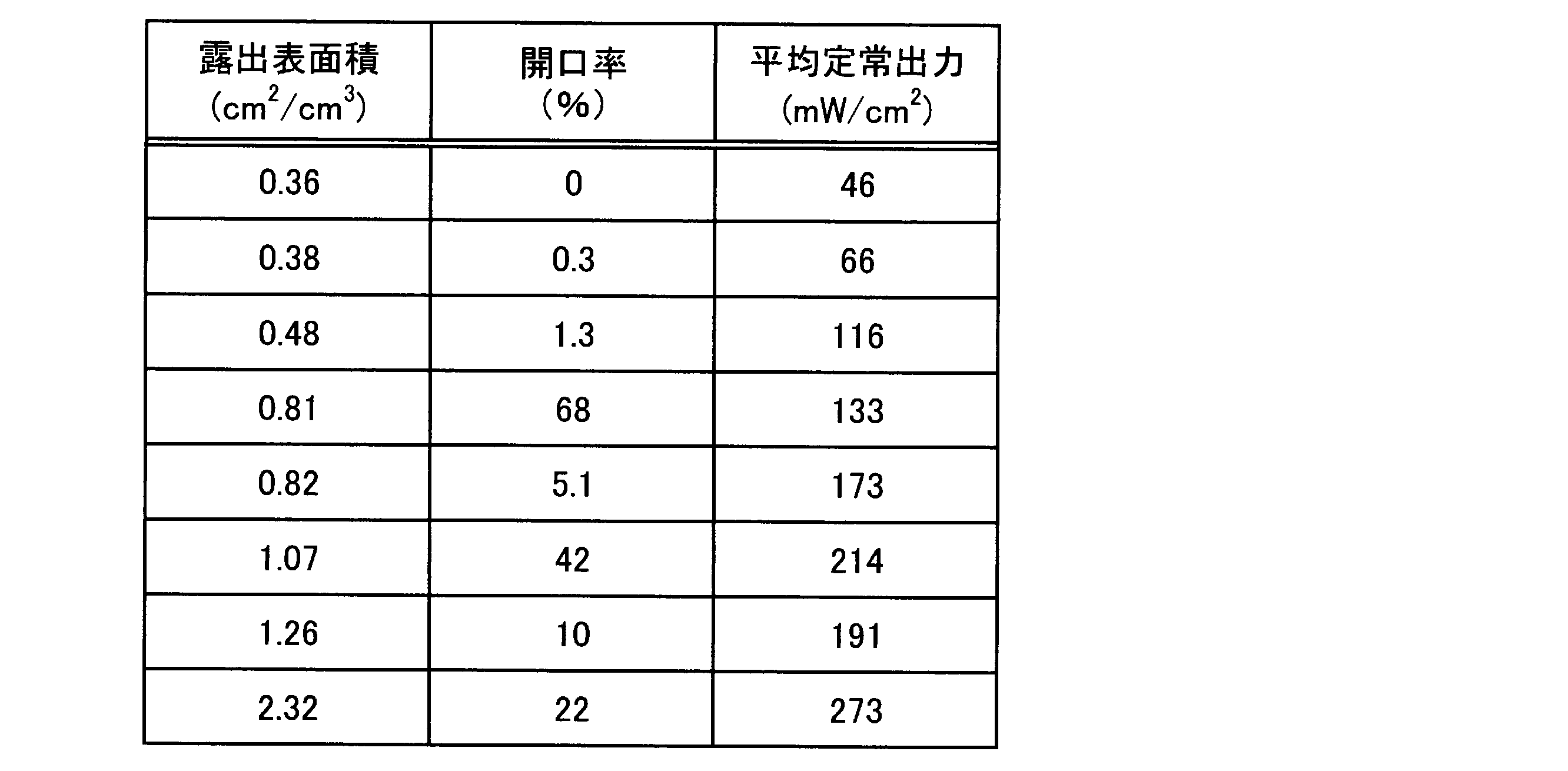
表2及び図18より、負極の露出表面積が大きくなるほど、微生物燃料電池の平均定常出力も向上することが分かる。このことからも、炭素材料の露出表面が多いほど、嫌気性微生物からグラフェンへの電子伝導性が高まるため、微生物燃料電池の出力が向上することが分かる。また、負極の露出表面の面積が0.4cm2/cm3以上の場合には、微生物燃料電池の出力がより向上することが分かる。
It can be seen from Table 2 and FIG. 18 that the average steady output of the microbial fuel cell is improved as the exposed surface area of the negative electrode is increased. This also shows that the more the exposed surface of the carbon material, the higher the electron conductivity from the anaerobic microorganisms to the graphene, so that the output of the microbial fuel cell is improved. Further, it can be seen that when the area of the exposed surface of the negative electrode is 0.4 cm 2 / cm 3 or more, the output of the microbial fuel cell is further improved.
以上、本実施形態を説明したが、本実施形態はこれらに限定されるものではなく、本実施形態の要旨の範囲内で種々の変形が可能である。具体的には、図面において、負極10、正極20及びイオン移動層30は、矩形状に形成されている。しかし、これらの形状は特に限定されず、燃料電池の大きさ、並びに所望の発電性能等により任意に変更することができる。また、各層の面積も所望の機能が発揮できるならば任意に変更することができる。
Although the present embodiment has been described above, the present embodiment is not limited to these, and various modifications are possible within the scope of the gist of the present embodiment. Specifically, in the drawing, the negative electrode 10, the positive electrode 20, and the ion transfer layer 30 are formed in a rectangular shape. However, these shapes are not particularly limited, and can be arbitrarily changed depending on the size of the fuel cell and the desired power generation performance. Further, the area of each layer can be arbitrarily changed as long as a desired function can be exhibited.
特願2016-146195号(出願日:2016年7月26日)の全内容は、ここに援用される。
The entire contents of Japanese Patent Application No. 2016-146195 (filing date: July 26, 2016) are incorporated herein by reference.
本発明によれば、電極の導電性を高め、発電による出力を向上させることが可能な微生物燃料電池を得ることができる。
According to the present invention, it is possible to obtain a microbial fuel cell capable of increasing the conductivity of the electrode and improving the output by power generation.
1 微生物燃料電池
2 気相
10 負極
11 炭素材料
12 グラフェン
13 貫通孔
20 正極
30 イオン移動層
70 電解液 DESCRIPTION OFSYMBOLS 1 Microbial fuel cell 2 Gas phase 10 Negative electrode 11 Carbon material 12 Graphene 13 Through-hole 20 Positive electrode 30 Ion transfer layer 70 Electrolyte
2 気相
10 負極
11 炭素材料
12 グラフェン
13 貫通孔
20 正極
30 イオン移動層
70 電解液 DESCRIPTION OF
Claims (6)
- 複数のグラフェンが積層した炭素材料からなり、前記炭素材料の体積に対する、前記炭素材料における前記グラフェンの積層方向に沿った露出表面の面積が1.0×10⁻⁵~20cm2/cm3である負極と、
前記負極と対向する正極と、
を有し、
前記負極及び前記正極が電解液に浸漬し、前記正極の少なくとも一部が気相に露出する、微生物燃料電池。 It is made of a carbon material in which a plurality of graphenes are stacked, and the area of the exposed surface along the stacking direction of the graphene in the carbon material with respect to the volume of the carbon material is 1.0 × 10 −5 to 20 cm 2 / cm 3 . A negative electrode,
A positive electrode facing the negative electrode;
Have
The microbial fuel cell, wherein the negative electrode and the positive electrode are immersed in an electrolytic solution, and at least a part of the positive electrode is exposed to a gas phase. - 前記負極において、前記炭素材料の体積に対する、前記炭素材料における前記グラフェンの積層方向に沿った露出表面の面積が0.4~7cm2/cm3である、請求項1に記載の微生物燃料電池。 The microbial fuel cell according to claim 1, wherein, in the negative electrode, an area of an exposed surface along a stacking direction of the graphene in the carbon material with respect to a volume of the carbon material is 0.4 to 7 cm 2 / cm 3 .
- 前記負極は、前記グラフェンの積層方向に沿った貫通孔を有する、請求項1又は2に記載の微生物燃料電池。 The microbial fuel cell according to claim 1 or 2, wherein the negative electrode has a through hole along a stacking direction of the graphene.
- 前記貫通孔を有する前記炭素材料の開口率が1~70%である、請求項3に記載の微生物燃料電池。 The microbial fuel cell according to claim 3, wherein an opening ratio of the carbon material having the through hole is 1 to 70%.
- 前記炭素材料は黒鉛シートである、請求項1乃至4のいずれか一項に記載の微生物燃料電池。 The microbial fuel cell according to any one of claims 1 to 4, wherein the carbon material is a graphite sheet.
- 前記負極と前記正極との間に設けられ、水素イオン透過性を有するイオン移動層をさらに有する、請求項1乃至5のいずれか一項に記載の微生物燃料電池。 The microbial fuel cell according to any one of claims 1 to 5, further comprising an ion transfer layer provided between the negative electrode and the positive electrode and having hydrogen ion permeability.
Priority Applications (4)
| Application Number | Priority Date | Filing Date | Title |
|---|---|---|---|
| JP2018529385A JPWO2018020807A1 (en) | 2016-07-26 | 2017-05-25 | Microbial fuel cell |
| CN201780045628.5A CN109478670A (en) | 2016-07-26 | 2017-05-25 | Microbiological fuel cell |
| US16/317,874 US20210280888A1 (en) | 2016-07-26 | 2017-05-25 | Microbial fuel cell |
| EP17833818.2A EP3493312A4 (en) | 2016-07-26 | 2017-05-25 | Microbial fuel cell |
Applications Claiming Priority (2)
| Application Number | Priority Date | Filing Date | Title |
|---|---|---|---|
| JP2016-146195 | 2016-07-26 | ||
| JP2016146195 | 2016-07-26 |
Publications (1)
| Publication Number | Publication Date |
|---|---|
| WO2018020807A1 true WO2018020807A1 (en) | 2018-02-01 |
Family
ID=61015964
Family Applications (1)
| Application Number | Title | Priority Date | Filing Date |
|---|---|---|---|
| PCT/JP2017/019489 WO2018020807A1 (en) | 2016-07-26 | 2017-05-25 | Microbial fuel cell |
Country Status (5)
| Country | Link |
|---|---|
| US (1) | US20210280888A1 (en) |
| EP (1) | EP3493312A4 (en) |
| JP (1) | JPWO2018020807A1 (en) |
| CN (1) | CN109478670A (en) |
| WO (1) | WO2018020807A1 (en) |
Cited By (1)
| Publication number | Priority date | Publication date | Assignee | Title |
|---|---|---|---|---|
| JP2019160454A (en) * | 2018-03-08 | 2019-09-19 | 国立研究開発法人農業・食品産業技術総合研究機構 | Electrode for bioelectrochemical system, bioelectrochemical system, and method for manufacturing electrode for bioelectrochemical system |
Families Citing this family (2)
| Publication number | Priority date | Publication date | Assignee | Title |
|---|---|---|---|---|
| CN113647118B (en) * | 2019-03-28 | 2024-03-08 | 住友理工株式会社 | Electrostatic transducer and electrostatic transducer unit |
| CN114694976B (en) * | 2022-03-02 | 2023-06-06 | 中国科学院山西煤炭化学研究所 | Super capacitor and preparation method thereof |
Citations (3)
| Publication number | Priority date | Publication date | Assignee | Title |
|---|---|---|---|---|
| JP2011065875A (en) * | 2009-09-17 | 2011-03-31 | Kurita Water Ind Ltd | Microorganism power generation device |
| WO2013073284A1 (en) * | 2011-11-16 | 2013-05-23 | 国立大学法人豊橋技術科学大学 | Microbial power generation device, electrode for microbial power generation device, and method for producing same |
| WO2016063455A1 (en) * | 2014-10-20 | 2016-04-28 | パナソニック株式会社 | Electrode, fuel cell and water treatment device |
Family Cites Families (1)
| Publication number | Priority date | Publication date | Assignee | Title |
|---|---|---|---|---|
| KR101817260B1 (en) * | 2013-02-22 | 2018-01-11 | 삼성전자주식회사 | Graphene-nanomaterial composite, electrode and electric device including the graphene-nanomaterial composite, and method of manufacturing the graphene-nanomaterial composite |
-
2017
- 2017-05-25 WO PCT/JP2017/019489 patent/WO2018020807A1/en unknown
- 2017-05-25 CN CN201780045628.5A patent/CN109478670A/en active Pending
- 2017-05-25 JP JP2018529385A patent/JPWO2018020807A1/en active Pending
- 2017-05-25 EP EP17833818.2A patent/EP3493312A4/en not_active Withdrawn
- 2017-05-25 US US16/317,874 patent/US20210280888A1/en not_active Abandoned
Patent Citations (3)
| Publication number | Priority date | Publication date | Assignee | Title |
|---|---|---|---|---|
| JP2011065875A (en) * | 2009-09-17 | 2011-03-31 | Kurita Water Ind Ltd | Microorganism power generation device |
| WO2013073284A1 (en) * | 2011-11-16 | 2013-05-23 | 国立大学法人豊橋技術科学大学 | Microbial power generation device, electrode for microbial power generation device, and method for producing same |
| WO2016063455A1 (en) * | 2014-10-20 | 2016-04-28 | パナソニック株式会社 | Electrode, fuel cell and water treatment device |
Non-Patent Citations (1)
| Title |
|---|
| See also references of EP3493312A4 * |
Cited By (2)
| Publication number | Priority date | Publication date | Assignee | Title |
|---|---|---|---|---|
| JP2019160454A (en) * | 2018-03-08 | 2019-09-19 | 国立研究開発法人農業・食品産業技術総合研究機構 | Electrode for bioelectrochemical system, bioelectrochemical system, and method for manufacturing electrode for bioelectrochemical system |
| JP6989923B2 (en) | 2018-03-08 | 2022-02-03 | 国立研究開発法人農業・食品産業技術総合研究機構 | Methods for manufacturing electrodes for bioelectrochemical systems, bioelectrochemical systems and electrodes for bioelectrochemical systems |
Also Published As
| Publication number | Publication date |
|---|---|
| US20210280888A1 (en) | 2021-09-09 |
| JPWO2018020807A1 (en) | 2019-05-16 |
| EP3493312A4 (en) | 2019-09-11 |
| CN109478670A (en) | 2019-03-15 |
| EP3493312A1 (en) | 2019-06-05 |
Similar Documents
| Publication | Publication Date | Title |
|---|---|---|
| JP6368036B2 (en) | Electrode structure and microbial fuel cell | |
| Sumisha et al. | Modification of graphite felt using nano polypyrrole and polythiophene for microbial fuel cell applications-a comparative study | |
| WO2015122125A1 (en) | Microbial fuel cell, microbial fuel cell system, and method for using microbial fuel cell | |
| WO2017119419A1 (en) | Gas diffusion electrode for microbial fuel cells and microbial fuel cell in which same is used | |
| WO2016143352A1 (en) | Microbial fuel cell system | |
| WO2018020807A1 (en) | Microbial fuel cell | |
| US20200317543A1 (en) | Purification unit and purification device | |
| JP6643642B2 (en) | Purification unit and purification device | |
| JP6438051B2 (en) | Microbial fuel cell system | |
| WO2018061058A1 (en) | Microbial fuel cell and waste liquid treatment system | |
| JP6703859B2 (en) | Microbial fuel cell | |
| JP2019076833A (en) | Liquid treatment system | |
| JP6660174B2 (en) | Method for producing electrode and method for producing membrane electrode assembly | |
| JP2020087804A (en) | Microbial fuel cell and liquid processing unit | |
| JP2017228411A (en) | Electrode composite and fuel cell | |
| WO2018203455A1 (en) | Liquid treatment system | |
| WO2017195406A1 (en) | Microbial fuel cell and liquid treatment unit using same | |
| JP2017041372A (en) | Microbial fuel cell and waste liquid processor | |
| JP2017148776A (en) | Water treatment equipment | |
| WO2019078002A1 (en) | Liquid processing system | |
| JP2017228410A (en) | Electrode and microbial fuel cell | |
| JP2020099850A (en) | Liquid treatment system | |
| WO2019064889A1 (en) | Liquid treatment system | |
| JP2017117586A (en) | Method of manufacturing electrode composite |
Legal Events
| Date | Code | Title | Description |
|---|---|---|---|
| 121 | Ep: the epo has been informed by wipo that ep was designated in this application |
Ref document number: 17833818 Country of ref document: EP Kind code of ref document: A1 |
|
| ENP | Entry into the national phase |
Ref document number: 2018529385 Country of ref document: JP Kind code of ref document: A |
|
| NENP | Non-entry into the national phase |
Ref country code: DE |
|
| ENP | Entry into the national phase |
Ref document number: 2017833818 Country of ref document: EP Effective date: 20190226 |